WO2022215400A1 - 緩衝器 - Google Patents
緩衝器 Download PDFInfo
- Publication number
- WO2022215400A1 WO2022215400A1 PCT/JP2022/009346 JP2022009346W WO2022215400A1 WO 2022215400 A1 WO2022215400 A1 WO 2022215400A1 JP 2022009346 W JP2022009346 W JP 2022009346W WO 2022215400 A1 WO2022215400 A1 WO 2022215400A1
- Authority
- WO
- WIPO (PCT)
- Prior art keywords
- valve
- chamber
- check valve
- piston
- hydraulic fluid
- Prior art date
- Legal status (The legal status is an assumption and is not a legal conclusion. Google has not performed a legal analysis and makes no representation as to the accuracy of the status listed.)
- Ceased
Links
Images


Classifications
-
- F—MECHANICAL ENGINEERING; LIGHTING; HEATING; WEAPONS; BLASTING
- F16—ENGINEERING ELEMENTS AND UNITS; GENERAL MEASURES FOR PRODUCING AND MAINTAINING EFFECTIVE FUNCTIONING OF MACHINES OR INSTALLATIONS; THERMAL INSULATION IN GENERAL
- F16F—SPRINGS; SHOCK-ABSORBERS; MEANS FOR DAMPING VIBRATION
- F16F9/00—Springs, vibration-dampers, shock-absorbers, or similarly-constructed movement-dampers using a fluid or the equivalent as damping medium
- F16F9/32—Details
- F16F9/44—Means on or in the damper for manual or non-automatic adjustment; such means combined with temperature correction
- F16F9/46—Means on or in the damper for manual or non-automatic adjustment; such means combined with temperature correction allowing control from a distance, i.e. location of means for control input being remote from site of valves, e.g. on damper external wall
- F16F9/465—Means on or in the damper for manual or non-automatic adjustment; such means combined with temperature correction allowing control from a distance, i.e. location of means for control input being remote from site of valves, e.g. on damper external wall using servo control, the servo pressure being created by the flow of damping fluid, e.g. controlling pressure in a chamber downstream of a pilot passage
-
- F—MECHANICAL ENGINEERING; LIGHTING; HEATING; WEAPONS; BLASTING
- F16—ENGINEERING ELEMENTS AND UNITS; GENERAL MEASURES FOR PRODUCING AND MAINTAINING EFFECTIVE FUNCTIONING OF MACHINES OR INSTALLATIONS; THERMAL INSULATION IN GENERAL
- F16F—SPRINGS; SHOCK-ABSORBERS; MEANS FOR DAMPING VIBRATION
- F16F9/00—Springs, vibration-dampers, shock-absorbers, or similarly-constructed movement-dampers using a fluid or the equivalent as damping medium
- F16F9/32—Details
- F16F9/34—Special valve constructions; Shape or construction of throttling passages
- F16F9/348—Throttling passages in the form of annular discs or other plate-like elements which may or may not have a spring action, operating in opposite directions or singly, e.g. annular discs positioned on top of the valve or piston body
-
- F—MECHANICAL ENGINEERING; LIGHTING; HEATING; WEAPONS; BLASTING
- F16—ENGINEERING ELEMENTS AND UNITS; GENERAL MEASURES FOR PRODUCING AND MAINTAINING EFFECTIVE FUNCTIONING OF MACHINES OR INSTALLATIONS; THERMAL INSULATION IN GENERAL
- F16F—SPRINGS; SHOCK-ABSORBERS; MEANS FOR DAMPING VIBRATION
- F16F9/00—Springs, vibration-dampers, shock-absorbers, or similarly-constructed movement-dampers using a fluid or the equivalent as damping medium
- F16F9/10—Springs, vibration-dampers, shock-absorbers, or similarly-constructed movement-dampers using a fluid or the equivalent as damping medium using liquid only; using a fluid of which the nature is immaterial
- F16F9/14—Devices with one or more members, e.g. pistons, vanes, moving to and fro in chambers and using throttling effect
- F16F9/16—Devices with one or more members, e.g. pistons, vanes, moving to and fro in chambers and using throttling effect involving only straight-line movement of the effective parts
- F16F9/18—Devices with one or more members, e.g. pistons, vanes, moving to and fro in chambers and using throttling effect involving only straight-line movement of the effective parts with a closed cylinder and a piston separating two or more working spaces therein
-
- F—MECHANICAL ENGINEERING; LIGHTING; HEATING; WEAPONS; BLASTING
- F16—ENGINEERING ELEMENTS AND UNITS; GENERAL MEASURES FOR PRODUCING AND MAINTAINING EFFECTIVE FUNCTIONING OF MACHINES OR INSTALLATIONS; THERMAL INSULATION IN GENERAL
- F16F—SPRINGS; SHOCK-ABSORBERS; MEANS FOR DAMPING VIBRATION
- F16F9/00—Springs, vibration-dampers, shock-absorbers, or similarly-constructed movement-dampers using a fluid or the equivalent as damping medium
- F16F9/32—Details
- F16F9/34—Special valve constructions; Shape or construction of throttling passages
-
- F—MECHANICAL ENGINEERING; LIGHTING; HEATING; WEAPONS; BLASTING
- F16—ENGINEERING ELEMENTS AND UNITS; GENERAL MEASURES FOR PRODUCING AND MAINTAINING EFFECTIVE FUNCTIONING OF MACHINES OR INSTALLATIONS; THERMAL INSULATION IN GENERAL
- F16F—SPRINGS; SHOCK-ABSORBERS; MEANS FOR DAMPING VIBRATION
- F16F9/00—Springs, vibration-dampers, shock-absorbers, or similarly-constructed movement-dampers using a fluid or the equivalent as damping medium
- F16F9/32—Details
- F16F9/34—Special valve constructions; Shape or construction of throttling passages
- F16F9/348—Throttling passages in the form of annular discs or other plate-like elements which may or may not have a spring action, operating in opposite directions or singly, e.g. annular discs positioned on top of the valve or piston body
- F16F9/3488—Throttling passages in the form of annular discs or other plate-like elements which may or may not have a spring action, operating in opposite directions or singly, e.g. annular discs positioned on top of the valve or piston body characterised by features intended to affect valve bias or pre-stress
-
- F—MECHANICAL ENGINEERING; LIGHTING; HEATING; WEAPONS; BLASTING
- F16—ENGINEERING ELEMENTS AND UNITS; GENERAL MEASURES FOR PRODUCING AND MAINTAINING EFFECTIVE FUNCTIONING OF MACHINES OR INSTALLATIONS; THERMAL INSULATION IN GENERAL
- F16F—SPRINGS; SHOCK-ABSORBERS; MEANS FOR DAMPING VIBRATION
- F16F9/00—Springs, vibration-dampers, shock-absorbers, or similarly-constructed movement-dampers using a fluid or the equivalent as damping medium
- F16F9/32—Details
- F16F9/44—Means on or in the damper for manual or non-automatic adjustment; such means combined with temperature correction
- F16F9/46—Means on or in the damper for manual or non-automatic adjustment; such means combined with temperature correction allowing control from a distance, i.e. location of means for control input being remote from site of valves, e.g. on damper external wall
-
- F—MECHANICAL ENGINEERING; LIGHTING; HEATING; WEAPONS; BLASTING
- F16—ENGINEERING ELEMENTS AND UNITS; GENERAL MEASURES FOR PRODUCING AND MAINTAINING EFFECTIVE FUNCTIONING OF MACHINES OR INSTALLATIONS; THERMAL INSULATION IN GENERAL
- F16F—SPRINGS; SHOCK-ABSORBERS; MEANS FOR DAMPING VIBRATION
- F16F9/00—Springs, vibration-dampers, shock-absorbers, or similarly-constructed movement-dampers using a fluid or the equivalent as damping medium
- F16F9/32—Details
- F16F9/50—Special means providing automatic damping adjustment, i.e. self-adjustment of damping by particular sliding movements of a valve element, other than flexions or displacement of valve discs; Special means providing self-adjustment of spring characteristics
- F16F9/512—Means responsive to load action, i.e. static load on the damper or dynamic fluid pressure changes in the damper, e.g. due to changes in velocity
-
- F—MECHANICAL ENGINEERING; LIGHTING; HEATING; WEAPONS; BLASTING
- F16—ENGINEERING ELEMENTS AND UNITS; GENERAL MEASURES FOR PRODUCING AND MAINTAINING EFFECTIVE FUNCTIONING OF MACHINES OR INSTALLATIONS; THERMAL INSULATION IN GENERAL
- F16F—SPRINGS; SHOCK-ABSORBERS; MEANS FOR DAMPING VIBRATION
- F16F9/00—Springs, vibration-dampers, shock-absorbers, or similarly-constructed movement-dampers using a fluid or the equivalent as damping medium
- F16F9/32—Details
- F16F9/50—Special means providing automatic damping adjustment, i.e. self-adjustment of damping by particular sliding movements of a valve element, other than flexions or displacement of valve discs; Special means providing self-adjustment of spring characteristics
- F16F9/512—Means responsive to load action, i.e. static load on the damper or dynamic fluid pressure changes in the damper, e.g. due to changes in velocity
- F16F9/5126—Piston, or piston-like valve elements
Definitions
- the present invention relates to a shock absorber that controls the flow of hydraulic fluid relative to the stroke of a piston to vary the damping force.
- Patent Document 1 discloses a damping force adjusting device configured to close an opening 54 (passage opening) of an orifice passage formed in a check valve 13 (disk valve) by a sub-check valve disk 45 (sub-check valve).
- a shock absorber 1 is disclosed.
- An object of the present invention is to provide a shock absorber that prevents hydraulic fluid from leaking from between a sub check valve provided at the opening of an orifice passage and a disc valve.
- the shock absorber of the present invention comprises a cylinder containing a hydraulic fluid, a reservoir containing the hydraulic fluid and gas, and a first chamber and a second chamber slidably inserted into the cylinder. a base valve that separates the second chamber from the reservoir; and a first reverse valve that is provided on the piston and allows hydraulic fluid to flow from the second chamber side to the first chamber side.
- a stop valve a stop valve, a second check valve provided in the base valve and allowing the hydraulic fluid to flow from the reservoir side to the second chamber side, a passage connecting the first chamber and the reservoir; a damping force adjustment mechanism capable of externally adjusting the damping force from a soft characteristic with a low damping force to a hard characteristic with a high damping force by controlling the flow of the hydraulic fluid in the passage;
- An orifice passage is provided in parallel with at least one of the valve and the second check valve, and a sub-check valve is provided at a passage opening of the orifice passage, and the sub-check valve is provided in parallel with the orifice passage.
- the sub-check valve is configured to open at a lower pressure to allow the flow of hydraulic fluid in the same direction, and the sub-check valve has a diameter substantially the same as that of the sub-check valve.
- a biasing member is provided that biases the sub check valve toward the passage opening.
- a shock absorber in which an orifice passage is formed in a disc valve stacked on a piston, operation from between a sub-check valve provided at the passage opening of the orifice passage and the disc valve Liquid leakage can be suppressed.
- FIG. 4 is a plan view of the biasing disc in the first embodiment;
- FIG. 1st Embodiment Comprising: (A) is a Lissajous waveform in the conventional buffer, (B) is a Lissajous waveform in the buffer based on 1st Embodiment. It is a sectional view of a shock absorber concerning a 2nd embodiment.
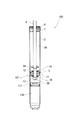
- the damper 1 shown in FIG. 1 is a so-called control valve-mounted damping force adjusting hydraulic damper in which the damping force adjusting mechanism 31 is laterally attached to the side wall of the outer tube 3 .
- the vertical direction in FIG. 1 is referred to as "vertical direction”.
- the left direction (left side) in FIG. 2 is referred to as “cylinder direction (cylinder side)”
- the right direction (right side) is referred to as "counter-cylinder direction (counter-cylinder side)”.
- the shock absorber 1 has a double-tube structure in which a cylinder 2 is provided inside an outer tube 3, and a reservoir 4 is formed between the cylinder 2 and the outer tube 3.
- a piston 5 is slidably inserted into the cylinder 2 to divide the inside of the cylinder 2 into two chambers, a first chamber 2A and a second chamber 2B.
- the shock absorber 1 includes a piston rod 6 whose lower end (one end) is connected to the piston 5 and whose upper end (the other end) extends out of the cylinder 2 through the first chamber 2A.
- a piston rod 6 is passed through a rod guide 7 attached to the upper end of the cylinder 2 .
- the first chamber 2 ⁇ /b>A and the outside are sealed by an oil seal 9 joined to a washer 8 .
- the piston 5 is provided with an extension side passage 11 and a compression side passage 12 that communicate the first chamber 2A and the second chamber 2B.
- the extension-side passage 11 is provided with a disk valve 121 that opens when the pressure on the side of the first chamber 2A reaches a set pressure to release the pressure on the side of the first chamber 2A to the side of the second chamber 2B.
- the contraction side passage 12 is provided with a disk valve 14 (first check valve) that allows the hydraulic fluid to flow from the second chamber 2B to the first chamber 2A.
- the disk valve 121 and the disk valve 14 are pressurized and clamped between the washers 38 and 38 by tightening the nut 13 screwed to the lower end of the piston rod 6 .
- a base valve 10 that separates the second chamber 2B and the reservoir 4 is provided at the lower end of the cylinder 2 .
- the base valve 10 is provided with an extension-side passage 15 and a contraction-side passage 16 that communicate the second chamber 2 ⁇ /b>B and the reservoir 4 .
- the extension-side passage 15 is provided with a check valve 17 (second check valve) that allows the hydraulic fluid to flow from the reservoir 4 side to the second chamber 2B side.
- the contraction side passage 16 is provided with a disc valve 18 that opens to release the pressure on the second chamber 2B side to the reservoir 4 side when the pressure on the second chamber 2B side reaches a set pressure.
- the cylinder 2 is filled with hydraulic fluid
- the reservoir 4 is filled with hydraulic fluid and gas.
- a separator tube 20 is attached to the outer circumference of the cylinder 2 . Between the cylinder 2 and the separator tube 20, an annular oil passage 21 sealed by a pair of upper and lower seal members 19, 19 is formed. An upper side wall of the cylinder 2 is provided with a passage 22 that communicates between the annular oil passage 21 and the first chamber 2A. The lower side wall of the separator tube 20 is provided with a cylindrical connection port 23 protruding toward the side opposite to the cylinder. A side wall of the outer tube 3 is provided with a mounting hole 24 coaxially with the connection port 23 . A cylindrical case 25 surrounding the mounting hole 24 is provided on the side wall of the outer tube 3 .
- the damping force adjustment mechanism 31 includes a valve block 33 integrated with valve parts, and a solenoid block 101 integrated with solenoid parts.
- the valve block 33 has a back pressure type main valve 41 , a pilot valve 61 that controls the valve opening pressure of the main valve 41 , and a fail-safe valve 91 provided downstream of the pilot valve 61 . That is, the damping force adjustment mechanism 31 is a pilot type pressure control valve that controls the opening pressure of the pilot valve 61 .
- a joint member 28 is inserted through the mounting hole 24 of the outer tube 3 .
- the joint member 28 includes a cylindrical tubular portion 29 whose end on the cylinder side is inserted into the connection port 23 , and a flange portion 30 provided on the peripheral edge of the opening of the tubular portion 29 on the side opposite to the cylinder and arranged in the case 25 . (outer flange) and The cylindrical portion 29 and the flange portion 30 are covered with a sealing material.
- the cylinder-side end surface of the flange portion 30 abuts against the end surface of the inner flange portion 26 of the case 25 on the opposite side of the cylinder, and the opposite end surface of the flange portion 30 abuts against the cylinder-side annular end surface (reference numerals omitted) of the main body 42 . touched.
- the channel 35 on the outer periphery of the valve block 33 and the reservoir 4 are communicated with each other by a plurality of grooves 27 provided in the inner flange portion 26 of the case 25 .
- the valve block 33 includes an annular main body 42 , an annular pilot body 62 , and a pilot pin 63 connecting the main body 42 and the pilot body 62 together.
- An annular seat portion 43 is formed on the outer peripheral edge of the end face of the main body 42 on the side opposite to the cylinder and protrudes toward the side opposite to the cylinder. The outer peripheral edge portion of the main disk 44 abuts on the seat portion 43 in a separable manner.
- the inner peripheral portion of the main disk 44 is clamped between the inner seat portion 45 of the main body 42 and the large diameter portion 64 of the pilot pin 63 .
- An annular packing 46 is provided on the outer peripheral portion of the main disk 44 on the side opposite to the cylinder.
- An annular recess 47 is provided in the end face of the main body 42 on the side opposite to the cylinder.
- an annular passage 48 is formed between the main body 42 and the main disk 44 .
- the annular passage 48 communicates with the flow path 35 through an orifice 52 formed in the main disk 44 .
- a recess 49 is formed in the center of the end face of the main body 42 on the cylinder side.
- the recessed portion 49 and the annular recessed portion 47 (annular passage 48 ) on the side opposite to the cylinder communicate with each other through a plurality of passages 50 (only “two” are shown in FIG. 2 ) formed in the main body 42 .
- the pilot pin 63 is formed in a bottomed cylindrical shape that is open on the side opposite to the cylinder.
- An introduction orifice 65 is formed at the bottom of the pilot pin 63 on the cylinder side.
- the cylinder side of the pilot pin 63 is press-fitted into the shaft hole 51 of the main body 42 .
- the side of the pilot pin 63 opposite to the cylinder is press-fitted into the shaft hole 66 of the pilot body 62 .
- a plurality of grooves 67 extending in the axial direction (“horizontal direction” in FIG. 2) are formed in the outer peripheral surface of the pilot pin 63 on the side opposite to the cylinder.
- the pilot body 62 is formed in a substantially bottomed cylindrical shape that is open on the side opposite to the cylinder.
- the cylinder side of the pilot body 62 is provided with a flexible disc 69 that is clamped by the inner peripheral portion 68 of the pilot body 62 and the large diameter portion 64 of the pilot pin 63 .
- a cylindrical portion 70 coaxial with the pilot body 62 is formed on the cylinder-side outer peripheral portion of the pilot body 62 .
- the packing 46 of the main valve 41 is slidably brought into contact with the inner peripheral surface (reference numeral omitted) of the cylindrical portion 70 .
- a pilot chamber 71 is defined on the opposite side (back surface) of the main disk 44 to the cylinder. The pressure in the pilot chamber 71 acts on the main disk 44 in the valve closing direction (the direction of pressing it against the seat portion 43).
- a plurality of passages 72 (only “two" are shown in FIG. 2) extending in the axial direction are provided at regular intervals in the circumferential direction.
- An annular chamber 74 is formed inside the seat portion 73 by seating the flexible disk 69 on the annular seat portion 73 provided on the end face of the pilot body 62 on the cylinder side.
- the chamber 74 opens on the cylinder side of the passage 72 .
- the flexible disk 69 bends under the internal pressure of the pilot chamber 71 to impart bulk elasticity to the pilot chamber 71 .
- the flexible disk 69 is constructed by laminating a plurality of disks.
- a notch 75 communicating between the groove 67 and the pilot chamber 71 is provided in the inner peripheral portion of the disk that contacts the large diameter portion 64 of the pilot pin 63 .
- the hydraulic fluid in the first chamber 2A is introduced into the damping force adjustment mechanism 31 through the passage 22, the annular oil passage 21, and the passage 36 (shaft hole) of the joint member 28, and is introduced into the introduction passage, that is, the introduction orifice. 65 , a shaft hole 76 of the pilot pin 63 , a groove 67 and a notch 75 , and are introduced into the pilot chamber 71 .
- the first chamber 2A is connected to the reservoir 4 by a passageway.
- the hydraulic fluid in the first chamber 2A is introduced into the damping force adjusting mechanism 31 through the passage 22, the annular oil passage 21, and the passage 36 (shaft hole) of the joint member 28, and the mounting hole 24 formed in the outer tube 3 to the reservoir 4 .
- a concave portion 77 is formed on the side of the pilot body 62 opposite to the cylinder.
- An annular seat portion 79 (valve seat) is formed at the center of the bottom portion of the concave portion 77 so that the valve body 78 can be seated and detached thereon.
- the seat portion 79 is provided on the periphery of the opening of the shaft hole 66 of the pilot body 62 through which the hydraulic fluid passes.
- the valve body 78 is formed in a substantially cylindrical shape, and the end on the cylinder side is formed in a tapered shape.
- An outer flange-shaped spring receiving portion 80 is provided on the opposite side of the valve body 78 to the cylinder. The valve body 78 is urged by the pilot spring 83 in the direction away from the seat portion 79 (the direction opposite to the cylinder).
- a cylindrical portion 81 is formed on the side of the pilot body 62 opposite to the cylinder.
- a pilot spring 83 , a spacer 93 , a fail-safe disk 94 , a retainer 95 , a spacer 96 and a washer 97 are stacked on the cylindrical portion 81 in this order from the cylinder side.
- the laminated parts are covered with a cap 98 attached to the outer circumference of the cylindrical portion 81 .
- the cap 98 is formed with a notch 99 that serves as a passage that communicates the recess 77 (valve chamber) and the flow path 35 .
- the solenoid block 101 is integrally formed by incorporating a coil 103, a core 104, a core 105, a plunger 106, and a hollow actuation rod 107 connected to the plunger 106 into a solenoid case 102.
- a spacer 108 and a cover 109 are inserted into the solenoid case 102 on the side opposite to the cylinder.
- Axial force is applied to parts inside the solenoid case 102 by plastically working the end edge of the solenoid case 102 on the side opposite to the cylinder.
- the plunger 106 is axially movably supported by sleeves 113 and 114 provided on the cores 104 and 105 .
- the plunger 106 generates thrust according to the current value by energizing the coil 103 .
- the thrust generated by the plunger 106 acts to move the valve body 78 in the direction toward the seat portion 79 (cylinder direction) against the biasing force of the pilot spring 83 .
- the cylinder side of the solenoid case 102 is inserted into the opening of the case 25 on the side opposite to the cylinder.
- a sealing member 110 seals between the solenoid case 102 and the case 25 .
- the cylinder side of the operating rod 107 protrudes into the recess 77 (valve chamber).
- a valve body 78 is attached to the end of the operating rod 107 on the cylinder side.
- valve body 78 When the coil 103 is not energized, the valve body 78 is urged in the direction opposite to the cylinder by the pilot spring 83 , and the spring receiving portion 80 of the valve body 78 abuts (seats) on the fail-safe disk 94 .
- the coil 103 when the coil 103 is energized, a thrust force is generated in the plunger 106 in the cylinder direction, and the operating rod 107 moves in the cylinder direction against the biasing force of the pilot spring 83 . to be seated.
- the valve opening pressure of the valve body 78 is controlled by changing the current value for energizing the coil 103 (hereinafter referred to as "control current value"). In the soft mode in which the control current value is small, the biasing force of the pilot spring 83 and the thrust of the plunger 106 are balanced, and the pilot valve 61 is opened with a constant valve opening amount.
- the disk valve 121 includes a plurality of disc valves clamped between the washer 38 and an annular inner seat portion 122 formed on the inner peripheral edge portion of the piston 5 on the second chamber 2B side (“lower side” in FIG. 3). It consists of a disk.
- the disk valve 121 has a disk 125 which abuts on an annular outer seat portion 123 formed on the outer peripheral edge of the piston 5 on the second chamber side so as to be separable and seatable.
- a plurality of circular openings 126 (only “one" is shown in FIG. 3) are provided in the disk 125 at regular intervals in the circumferential direction.
- An annular concave portion 124 is formed between the inner seat portion 122 and the outer seat portion 123 .
- the disk valve 121 has a disk 127 superimposed on the opposite side of the disk 125 ("lower side” in FIG. 3).
- Disk 127 has the same outer diameter as disk 125 .
- a plurality of notches 128 (only “one” is shown in FIG. 3) extending radially inward (“leftward” in FIG. 3) are provided at the outer peripheral edge of the disk 127 at regular intervals in the circumferential direction.
- the number of notches 128 is the same as the number of openings 126 provided in disk 125, and disk 125 and disk 127 are positioned about the axis so that openings 126 and notches 128 match (communicate). .
- the disk valve 121 has a plurality of (“six” in the first embodiment) disks 129 stacked on the opposite side of the disk 127 to the piston.
- Disk 129 has the same outer diameter as disks 125 and 127 .
- the configuration is described above, but the discs 127 and 125 may have different outer diameters, and the notches 128 may be provided at uneven intervals. Further, although it is desirable to position the discs 125 and 127, they may not be positioned depending on the shape and size of the notch or opening.
- the disk valve 121 (the plurality of disks stacked on the piston 5) has a plurality of (only one shown in FIG. 3) consisting of the notch 128 of the disk 127 and the opening 126 of the disk 125.
- An orifice passage 130 is configured.
- the orifice passage 130 is provided on the second chamber 2B side of the piston 5 and arranged in parallel with the disc valve 14 (first check valve) provided in the first chamber 2A of the piston 5 .
- Orifice passage 130 allows hydraulic fluid in second chamber 2B to flow through extension side passage 11 to first chamber 2A when the piston speed in the compression stroke is low (0.1 m/s or less, not including 0).
- the orifice area of orifice passage 130 is the rectangular cross-sectional area of notch 128 .
- a spacer 131 and a retainer 132 are stacked on the side of the disc 129 opposite to the piston.
- a disc-shaped sub-check valve 133 is superimposed on the piston side of the disc 125 ("upper side" in FIG. 3).
- the outer diameter of the sub check valve 133 is set so as to be able to block the opening 126 of the disk 125 and, by extension, the opening 126 (passage opening) of the orifice passage 130 .
- the outer diameter of the sub check valve 133 is set so that the outer peripheral edge does not contact the piston 5, that is, the opening of the valve (separation from the disk 125) is not hindered.
- the sub-check valve 133 as a valve element does not allow flow from one direction and completely rejects flow from the other direction, but includes those that slightly allow flow from the other direction.
- the outer seat portion 123 has a larger amount of protrusion from the piston 5 than the inner seat portion 122 . That is, a certain level difference is formed between the inner sheet portion 122 and the outer sheet portion 123 . Therefore, the disc valve 121 is pushed up by the outer seat portion 123 and bent (elastically deformed), and a set load acts on the disc valve 121 .
- a biasing disk 135 (biasing member) is provided on the piston side of the sub check valve 133 .
- the urging disk 135 urges the sub check valve 133 toward the disk valve 121 toward the anti-piston side and presses (closely contacts) the sub check valve 133 against the disk 125, thereby opening 126 ( passage openings).
- the biasing disk 135 has a shaft hole 136 (insertion hole) through which the piston rod 6 is inserted.
- An inner peripheral portion 137 that is clamped between the inner seat portion 122 of the piston 5 and the disk valve 121 together with the inner peripheral portion (reference numeral omitted) of the sub-check valve 133 is formed on the peripheral edge of the shaft hole 136 .
- the urging disk 135 is formed with a projection 138 extending annularly along the outer peripheral edge.
- the projection 138 is formed in an arcuate cross-section along the axial plane of the biasing disk 135 protruding toward the anti-piston side ("lower side" in FIG. 3).
- the protrusion 138 is arranged opposite the opening 126 (passage opening) of the orifice passage 130 (disk 125).
- the outer peripheral portion of the sub check valve 133 is pressed toward the opening 126 of the orifice passage 130 .
- the biasing disk 135 has substantially the same diameter as the sub check valve 133 .
- substantially the same diameter means that the diameter of the urging disk 135 is such that the projection 138 can be arranged facing the opening 126 of the orifice passage 130 without hindering the opening of the sub-check valve 133. diameter and includes the same outer diameter as sub-check valve 133 .
- the urging disk 135 has a plurality of ("four" in the first embodiment) holes 139 formed on the inner peripheral side of the projection 138. As shown in FIG. The holes 139 extend with a constant width along the protrusion 138 and are arranged at regular intervals around the outer periphery of the shaft hole 136 .
- the biasing force of the biasing disk 135 causes the sub check valve 133 to open at a lower pressure than the disk valve 14 (first check valve) provided on the first chamber 2A side of the piston 5. is set to That is, the sub-check valve 133 opens at a pressure lower than that of the disc valve 14 during the compression stroke, thereby generating a damping force with an orifice characteristic by the orifice passage 130 .
- the disk valve 14 (first check valve) of the piston 5 closes due to the pressure increase in the first chamber 2A, and before the disk valve 121 opens, the hydraulic fluid in the first chamber 2A is added. pressured.
- the pressurized hydraulic fluid is introduced into the damping force adjustment mechanism 31 through the passage 22 , the annular oil passage 21 , and the passage 36 (shaft hole) of the joint member 28 .
- the hydraulic fluid corresponding to the movement of the piston 5 flows from the reservoir 4 into the second chamber 2B by opening the check valve 17 of the base valve 10 .
- the disk valve 121 of the piston 5 and the check valve 17 (second check valve) of the base valve 10 are closed due to the pressure increase in the second chamber 2B, and the disk valve 18 of the base valve 10 is opened.
- the hydraulic fluid in the second chamber 2B is pressurized.
- the piston speed in the compression stroke is low (0.1 m/s or less, not including 0)
- the hydraulic fluid in the second chamber 2B is sub-checked against the biasing force of the biasing disk 135 (biasing member).
- the valve 133 is opened, passes through the orifice passage 130 formed in the disc valve 121, the annular recess 124, the extension side passage 11, and the piston orifice 300 formed by coining, and the disc valve 14 is closed. Flow to 1 chamber 2A.
- the damper 1 generates an orifice characteristic damping force by the orifice passage 130 .
- the hydraulic fluid introduced into the damping force adjustment mechanism 31 is introduced into the pilot chamber 71 through the introduction passage, that is, the introduction orifice 65, the shaft hole 76 of the pilot pin 63, the groove 67, and the notch 75.
- the hydraulic fluid introduced into the damping force adjustment mechanism 31 passes through the introduction orifice 65, the shaft hole 76 of the pilot pin 63, and the pilot body 62 before the main valve 41 opens (when the piston speed is in the low speed range).
- recess 77 valve chamber
- notch 99 formed in cap 98 flow path 35 on the outer circumference of valve block 33, a plurality of grooves 27 formed in case 25, and mounting holes formed in outer tube 3 24 to reservoir 4 .
- the hydraulic fluid opens the main valve 41 and causes the flow around the valve block 33 to flow. It flows to the reservoir 4 through the channel 35 , a plurality of grooves 27 formed in the case 25 and the attachment holes 24 formed in the outer tube 3 .
- the damping force adjustment mechanism 31 allows hydraulic fluid to flow through the introduction orifice before the main valve 41 opens (when the piston speed is in the low speed range) during both the extension stroke and the compression stroke of the piston rod 6.
- a damping force is generated by passing through 65 and pilot valve 61 .
- a damping force with valve characteristics corresponding to the opening of the main valve 41 is generated.
- the biasing force of the pilot spring 83 (which also serves as a fail-safe spring) moves the valve body 78 to the side opposite to the cylinder. , the pilot valve 61 is opened and the spring receiving portion 80 of the valve body 78 is brought into contact with the fail-safe disk 94 to cut off the communication between the flow path (reference numerals omitted) inside the valve block 33 and the flow path 35 outside. do.
- the valve opening pressure of the fail-safe valve 91 is adjusted, and from the first chamber 2A, the passage, that is, the passage 22, the annular oil passage 21, the passage 36 (shaft hole) of the joint member 28, the damping force adjustment mechanism 31 , a plurality of grooves 27 formed in the case 25, and a mounting hole 24 formed in the outer tube 3 to control the flow of hydraulic fluid to the reservoir 4, thereby generating a constant damping force when a failure occurs.
- the internal pressure of the pilot chamber 71 and, in turn, the opening pressure of the main valve 41 so that a constant damping force can be obtained even when a failure occurs.
- a conventional shock absorber hereinafter referred to as "conventional ), the outer seat portion 123 is higher than the inner seat portion 122 (the amount of protrusion from the piston 5 is large), and the sub check valve 133 is not seated on the outer seat portion 123 (outer seat smaller outer diameter than the portion 123). Therefore, in the conventional shock absorber, when the piston speed in the extension stroke is low (0.1 m/s or less, not including 0), the hydraulic fluid in the first chamber 2A is sub-reverse to the disk valve 121 (disk 125). It may leak into the second chamber 2B from between the stop valve 133 and the intended damping force (predetermined damping force) may not be obtained.
- the sub check valve 133 is biased toward the opening 126 of the orifice passage 130 by the biasing disk 135 (biasing member) having substantially the same diameter as the sub check valve 133 .
- the shock absorber 1 was constructed in As a result, when the piston speed in the extension stroke is low (0.1 m/s or less, not including 0), the hydraulic fluid in the first chamber 2A flows from between the disk valve 121 and the sub check valve 133 to the second chamber. Leakage to 2B is suppressed, and the intended damping force can be obtained.
- the annular protrusion 138 formed on the biasing disk 135 biases (presses) the outer peripheral side of the sub check valve 133 in the direction opposite to the piston to bring it into close contact with the disk valve 121. Therefore, it is possible to reliably prevent a gap from being formed between the disc valve 121 and the sub check valve 133 .
- a plurality of holes 139 extending along the inner periphery of the projection 138 are provided between the projection 138 and the shaft hole 136 (insertion hole) of the urging disk 135.
- the disk 135 can be made less rigid.
- the sub check valve 133 is opened before the disc valve 14 (first check valve) provided on the first chamber 2A side of the piston 5 is opened.
- the orifice passage 130 can provide orifice characteristic damping force.
- FIG. 5A shows the Lissajous waveform in a conventional shock absorber without the biasing disk 135, and FIG. is.
- the damping force F0 (see FIG. 5A) generated by the conventional shock absorber when the piston speed in the extension stroke is extremely low (for example, "0.05 m/s") and the A comparison is made with the damping force F1 (see FIG. 5(B)) generated by the shock absorber 1 .
- the damping force F1 generated by the shock absorber 1 according to the first embodiment is larger than the damping force F0 generated by the conventional shock absorber (F1>F0).
- the damping force F0 generated by the conventional shock absorber is "1”
- the damping force F1 generated by the shock absorber 1 according to the first embodiment is approximately "2".
- the disc valve 121 and the sub check valve 133 are biased toward the opening 126 (passage opening) of the orifice passage 130 by the biasing disc 135 . It can be seen that leakage of hydraulic fluid from between the check valve 133 is suppressed, and the intended damping force is obtained even when the piston speed in the extension stroke is extremely low. Thus, in the first embodiment, it is possible to improve the ride comfort of the vehicle when the piston speed is extremely low.
- the disc valve 121 and the sub check valve 133 are biased toward the opening 126 (passage opening) of the orifice passage 130 by the biasing disc 135 . Leakage of the hydraulic fluid from between the check valve 133 is suppressed, and when the piston stroke is reversed when the piston speed is low, there is no lack in the waveform S1 and the rise of the damping force is not delayed. It can be seen that a damping force is obtained.
- the Lissajous waveform of the contraction stroke in the conventional shock absorber is substantially the same. That is, the damping force during the contraction stroke in the shock absorber 1 according to the first embodiment differs from the damping force during the contraction stroke in the conventional shock absorber because the biasing disk 135 is provided in the sub check valve 133. It can be seen that there is no change due to Thus, in the first embodiment, damping force characteristics equivalent to those of the conventional shock absorber can be obtained in the contraction stroke.
- a valve structure (hereinafter referred to as "the first ) can be provided on the first chamber 2A side of the piston 5 to configure the shock absorber 1. That is, in the first embodiment, the sub check valve 133 is arranged on the second chamber 2B side of the piston 5, but the disk valve 121 is arranged on the first chamber 2A side of the piston 5, and is arranged on the farthest opposite piston side.
- the shock absorber 1 is configured such that the sub check valve 133 is biased toward the piston side toward the opening 126 (passage opening) of the orifice passage 130 formed in the disc valve 121 by the biasing disc 135 (biasing member). can do.
- the piston orifice 300 formed by coining is not provided.
- the hydraulic fluid in the second chamber 2B is prevented from leaking into the first chamber 2A from between the disc valve 121 and the sub-check valve 133, and the intended damping is achieved. power can be obtained.
- the hydraulic fluid in the second chamber 2B is prevented from leaking into the first chamber 2A from between the disc valve 121 and the sub check valve 133.
- the present invention may be applied to the contraction stroke.
- valve structure of the first embodiment can be provided in the base valve 10 to configure the shock absorber 1 . That is, in the first embodiment, the orifice passage 130 is provided in parallel with the disk valve 14 (first check valve) provided in the piston 5, and the opening 126 (passage opening) of the orifice passage 130 is provided with a sub-check valve. Although the valve 135 is provided, the disk valve 121 is provided on the reservoir 4 side of the base valve 10, and the orifice passage 130 is provided in parallel with the check valve 17 (second check valve) provided on the base valve 10.
- a biasing disc 135 biases the sub check valve 133 toward the opening 126 (passage opening) of the orifice passage 130 formed in the disc valve 121 toward the side opposite to the base valve.
- a device 1 can be configured. In this case, when the piston speed in the compression stroke is low, the hydraulic fluid in the second chamber 2B is prevented from leaking into the reservoir 4 from between the disc valve 121 and the sub check valve 133, thereby reducing the intended damping force. Obtainable.
- the valve structure is applied to the shock absorber 1 provided with the damping force adjustment mechanism 31 (pilot type pressure control valve) that adjusts the valve opening pressure of the pilot valve 61 by energizing the coil 103.
- the valve structure of the first embodiment is replaced by a shock absorber (not shown) having a damping force adjustment mechanism (pilot type flow control valve) that adjusts the valve opening area of the pilot valve 61 by energizing the coil 103. ) can be applied to In this case, effects equivalent to those of the first embodiment described above can be obtained.
- the damping force adjusting mechanism 31 is attached to the side wall of the outer tube 3 in the double-tube shock absorber 1, that is, the damping force adjusting hydraulic shock absorber of the control valve side-mounted type, as shown in FIG. A valve structure was applied.
- the valve structure of the first embodiment is applied to the single-tube shock absorber 100. As shown in FIG.
- the shock absorber 100 has a cylinder 2 filled with hydraulic fluid, a piston 5 slidably inserted into the cylinder 2, and a free piston 117.
- the piston 5 partitions the interior of the cylinder 2 into a first chamber 2A and a second chamber 2B.
- the free piston 117 defines a gas chamber 118 at the bottom of the cylinder 2 .
- a disk valve 14 (first damping valve) is provided on the first chamber 2A side of the piston 5 to allow the hydraulic fluid to flow from the second chamber 2B to the first chamber 2A.
- a disc valve 121 made up of a plurality of discs is stacked on the second chamber 2B side of the piston 5 .
- the disc valve 121 is configured with an orifice passage 130 provided in parallel with the disc valve 14 (first damping valve).
- the opening 126 (passage opening) of the orifice passage 130 is opened at a lower pressure than the disk valve 14 to allow the hydraulic fluid to flow in the same direction (direction from the second chamber 2B to the first chamber 2A).
- a sub check valve 133 is provided.
- the sub check valve 133 is provided with a biasing disk 135 (biasing member) that biases the sub check valve 133 toward the opening 126 (passage opening) of the orifice passage 130 .
- the urging disk 135 is provided separately from the sub-check valve 133.
- an R portion projecting toward the annular recess 124 is formed at least in the vicinity of the opening 126 of the sub-check valve.
- an urging seat portion that urges the sub check valve 133 is provided between the inner seat portion 122 and the outer seat portion 123 of the piston 5, and the sub check valve 133 is pushed toward the disk valve 121 by the urging seat portion. It may be configured to be biased. In that case, it is preferable that the urging seat portion is positioned or protruded at a height that does not obstruct the opening of the sub check valve 133 . Also, the urging disk 135 need not be disk-shaped as in the second embodiment, and may be a star spring or a coil spring.
- the present invention is not limited to the above-described embodiments, and includes various modifications.
- the above-described embodiments have been described in detail in order to explain the present invention in an easy-to-understand manner, and are not necessarily limited to those having all the configurations described.
- part of the configuration of one embodiment can be replaced with the configuration of another embodiment, and the configuration of another embodiment can be added to the configuration of one embodiment.
Landscapes
- Engineering & Computer Science (AREA)
- General Engineering & Computer Science (AREA)
- Mechanical Engineering (AREA)
- Physics & Mathematics (AREA)
- Fluid Mechanics (AREA)
- Fluid-Damping Devices (AREA)
Priority Applications (5)
| Application Number | Priority Date | Filing Date | Title |
|---|---|---|---|
| JP2023512865A JP7710032B2 (ja) | 2021-04-09 | 2022-03-04 | 緩衝器 |
| KR1020237023866A KR102888661B1 (ko) | 2021-04-09 | 2022-03-04 | 완충기 |
| US18/282,051 US20240191768A1 (en) | 2021-04-09 | 2022-03-04 | Shock absorber |
| CN202280023348.5A CN117062996A (zh) | 2021-04-09 | 2022-03-04 | 缓冲器 |
| DE112022002051.2T DE112022002051T5 (de) | 2021-04-09 | 2022-03-04 | Stossdämpfer |
Applications Claiming Priority (2)
| Application Number | Priority Date | Filing Date | Title |
|---|---|---|---|
| JP2021066573 | 2021-04-09 | ||
| JP2021-066573 | 2021-04-09 |
Publications (1)
| Publication Number | Publication Date |
|---|---|
| WO2022215400A1 true WO2022215400A1 (ja) | 2022-10-13 |
Family
ID=83545856
Family Applications (1)
| Application Number | Title | Priority Date | Filing Date |
|---|---|---|---|
| PCT/JP2022/009346 Ceased WO2022215400A1 (ja) | 2021-04-09 | 2022-03-04 | 緩衝器 |
Country Status (6)
| Country | Link |
|---|---|
| US (1) | US20240191768A1 (https=) |
| JP (1) | JP7710032B2 (https=) |
| KR (1) | KR102888661B1 (https=) |
| CN (1) | CN117062996A (https=) |
| DE (1) | DE112022002051T5 (https=) |
| WO (1) | WO2022215400A1 (https=) |
Cited By (1)
| Publication number | Priority date | Publication date | Assignee | Title |
|---|---|---|---|---|
| WO2024185396A1 (ja) * | 2023-03-09 | 2024-09-12 | カヤバ株式会社 | 減衰バルブおよび緩衝器 |
Citations (5)
| Publication number | Priority date | Publication date | Assignee | Title |
|---|---|---|---|---|
| JPS6317342U (https=) * | 1986-07-19 | 1988-02-04 | ||
| JPH0325038U (https=) * | 1989-07-24 | 1991-03-14 | ||
| JP2013113425A (ja) * | 2011-11-30 | 2013-06-10 | Hitachi Automotive Systems Ltd | 流体圧緩衝器 |
| JP5812650B2 (ja) * | 2011-03-31 | 2015-11-17 | 日立オートモティブシステムズ株式会社 | 減衰力調整式緩衝器 |
| JP2016089898A (ja) * | 2014-10-31 | 2016-05-23 | 日立オートモティブシステムズ株式会社 | 流体圧緩衝器 |
Family Cites Families (3)
| Publication number | Priority date | Publication date | Assignee | Title |
|---|---|---|---|---|
| JP5365804B2 (ja) * | 2009-12-22 | 2013-12-11 | 日立オートモティブシステムズ株式会社 | 緩衝器 |
| KR102559735B1 (ko) * | 2018-12-25 | 2023-07-25 | 히다치 아스테모 가부시키가이샤 | 완충기 |
| JP2021066573A (ja) | 2019-10-25 | 2021-04-30 | キヤノン株式会社 | シート供給装置およびプリント装置 |
-
2022
- 2022-03-04 KR KR1020237023866A patent/KR102888661B1/ko active Active
- 2022-03-04 DE DE112022002051.2T patent/DE112022002051T5/de active Pending
- 2022-03-04 JP JP2023512865A patent/JP7710032B2/ja active Active
- 2022-03-04 WO PCT/JP2022/009346 patent/WO2022215400A1/ja not_active Ceased
- 2022-03-04 CN CN202280023348.5A patent/CN117062996A/zh active Pending
- 2022-03-04 US US18/282,051 patent/US20240191768A1/en active Pending
Patent Citations (5)
| Publication number | Priority date | Publication date | Assignee | Title |
|---|---|---|---|---|
| JPS6317342U (https=) * | 1986-07-19 | 1988-02-04 | ||
| JPH0325038U (https=) * | 1989-07-24 | 1991-03-14 | ||
| JP5812650B2 (ja) * | 2011-03-31 | 2015-11-17 | 日立オートモティブシステムズ株式会社 | 減衰力調整式緩衝器 |
| JP2013113425A (ja) * | 2011-11-30 | 2013-06-10 | Hitachi Automotive Systems Ltd | 流体圧緩衝器 |
| JP2016089898A (ja) * | 2014-10-31 | 2016-05-23 | 日立オートモティブシステムズ株式会社 | 流体圧緩衝器 |
Cited By (1)
| Publication number | Priority date | Publication date | Assignee | Title |
|---|---|---|---|---|
| WO2024185396A1 (ja) * | 2023-03-09 | 2024-09-12 | カヤバ株式会社 | 減衰バルブおよび緩衝器 |
Also Published As
| Publication number | Publication date |
|---|---|
| JP7710032B2 (ja) | 2025-07-17 |
| KR102888661B1 (ko) | 2025-11-19 |
| JPWO2022215400A1 (https=) | 2022-10-13 |
| DE112022002051T5 (de) | 2024-03-07 |
| CN117062996A (zh) | 2023-11-14 |
| KR20230116934A (ko) | 2023-08-04 |
| US20240191768A1 (en) | 2024-06-13 |
Similar Documents
| Publication | Publication Date | Title |
|---|---|---|
| US10619694B2 (en) | Shock absorber | |
| KR101850337B1 (ko) | 완충기 | |
| US8413774B2 (en) | Shock absorber | |
| US9597941B2 (en) | Cylinder apparatus | |
| JP6465983B2 (ja) | 緩衝器 | |
| JP2018013208A (ja) | 減衰力調整式緩衝器 | |
| US12181018B2 (en) | Shock absorber | |
| JP7485579B2 (ja) | 減衰バルブおよび緩衝器 | |
| US12066075B2 (en) | Shock absorber | |
| JP7296268B2 (ja) | 減衰力調整式緩衝器 | |
| WO2022215400A1 (ja) | 緩衝器 | |
| WO2023067941A1 (ja) | 緩衝器の製造方法 | |
| JP7416672B2 (ja) | 減衰力調整式緩衝器及び減衰力調整弁 | |
| JP7129565B2 (ja) | 減衰力調整式緩衝器 | |
| JP7129385B2 (ja) | 減衰力調整式緩衝器 | |
| JP7171495B2 (ja) | 緩衝器 | |
| KR102627961B1 (ko) | 감쇠력 조정식 완충기 | |
| WO2022168817A1 (ja) | 緩衝器 | |
| JP2022152580A (ja) | 緩衝器 | |
| JP2017096453A (ja) | 緩衝器 | |
| JP7378010B2 (ja) | 緩衝器及びバルブ装置 | |
| KR102855080B1 (ko) | 감쇠력 조정식 완충기, 감쇠 밸브 및 솔레노이드 | |
| JP7450057B2 (ja) | 制御弁装置 | |
| JP7531063B2 (ja) | 制御弁装置 | |
| WO2022249623A1 (ja) | 緩衝器及び緩衝器の製造方法 |
Legal Events
| Date | Code | Title | Description |
|---|---|---|---|
| 121 | Ep: the epo has been informed by wipo that ep was designated in this application |
Ref document number: 22784385 Country of ref document: EP Kind code of ref document: A1 |
|
| ENP | Entry into the national phase |
Ref document number: 2023512865 Country of ref document: JP Kind code of ref document: A |
|
| ENP | Entry into the national phase |
Ref document number: 20237023866 Country of ref document: KR Kind code of ref document: A |
|
| WWE | Wipo information: entry into national phase |
Ref document number: 18282051 Country of ref document: US |
|
| WWE | Wipo information: entry into national phase |
Ref document number: 202280023348.5 Country of ref document: CN |
|
| WWE | Wipo information: entry into national phase |
Ref document number: 112022002051 Country of ref document: DE |
|
| 122 | Ep: pct application non-entry in european phase |
Ref document number: 22784385 Country of ref document: EP Kind code of ref document: A1 |