WO2022215265A1 - 工作機械の電気的接続構造 - Google Patents
工作機械の電気的接続構造 Download PDFInfo
- Publication number
- WO2022215265A1 WO2022215265A1 PCT/JP2021/015068 JP2021015068W WO2022215265A1 WO 2022215265 A1 WO2022215265 A1 WO 2022215265A1 JP 2021015068 W JP2021015068 W JP 2021015068W WO 2022215265 A1 WO2022215265 A1 WO 2022215265A1
- Authority
- WO
- WIPO (PCT)
- Prior art keywords
- machine tool
- working member
- energization
- bypass path
- connection structure
- Prior art date
- Legal status (The legal status is an assumption and is not a legal conclusion. Google has not performed a legal analysis and makes no representation as to the accuracy of the status listed.)
- Ceased
Links
Images


Classifications
-
- B—PERFORMING OPERATIONS; TRANSPORTING
- B25—HAND TOOLS; PORTABLE POWER-DRIVEN TOOLS; MANIPULATORS
- B25J—MANIPULATORS; CHAMBERS PROVIDED WITH MANIPULATION DEVICES
- B25J19/00—Accessories fitted to manipulators, e.g. for monitoring, for viewing; Safety devices combined with or specially adapted for use in connection with manipulators
-
- B—PERFORMING OPERATIONS; TRANSPORTING
- B25—HAND TOOLS; PORTABLE POWER-DRIVEN TOOLS; MANIPULATORS
- B25J—MANIPULATORS; CHAMBERS PROVIDED WITH MANIPULATION DEVICES
- B25J19/00—Accessories fitted to manipulators, e.g. for monitoring, for viewing; Safety devices combined with or specially adapted for use in connection with manipulators
- B25J19/06—Safety devices
-
- G—PHYSICS
- G05—CONTROLLING; REGULATING
- G05B—CONTROL OR REGULATING SYSTEMS IN GENERAL; FUNCTIONAL ELEMENTS OF SUCH SYSTEMS; MONITORING OR TESTING ARRANGEMENTS FOR SUCH SYSTEMS OR ELEMENTS
- G05B19/00—Program-control systems
- G05B19/02—Program-control systems electric
- G05B19/18—Numerical control [NC], i.e. automatically operating machines, in particular machine tools, e.g. in a manufacturing environment, so as to execute positioning, movement or co-ordinated operations by means of program data in numerical form
-
- G—PHYSICS
- G05—CONTROLLING; REGULATING
- G05B—CONTROL OR REGULATING SYSTEMS IN GENERAL; FUNCTIONAL ELEMENTS OF SUCH SYSTEMS; MONITORING OR TESTING ARRANGEMENTS FOR SUCH SYSTEMS OR ELEMENTS
- G05B9/00—Safety arrangements
- G05B9/02—Safety arrangements electric
-
- H—ELECTRICITY
- H02—GENERATION; CONVERSION OR DISTRIBUTION OF ELECTRIC POWER
- H02H—EMERGENCY PROTECTIVE CIRCUIT ARRANGEMENTS
- H02H3/00—Emergency protective circuit arrangements for automatic disconnection directly responsive to an undesired change from normal electric working condition with or without subsequent reconnection ; integrated protection
- H02H3/08—Emergency protective circuit arrangements for automatic disconnection directly responsive to an undesired change from normal electric working condition with or without subsequent reconnection ; integrated protection responsive to excess current
Definitions
- the present invention relates to a machine tool such as a machine tool robot and an NC machine tool. It relates to a connection structure.
- Japanese Patent Application Laid-Open No. 2019-89143 includes a plurality of circuit boards that acquire and process signals from a plurality of sensor units, and one of the plurality of circuit boards has two or more sensors among the plurality of sensor units. Techniques for miniaturizing (slimming) and reducing the weight of robots by acquiring signals from parts have been proposed.
- Japanese Patent Application Laid-Open No. 2018-94656 discloses that a signal for controlling the transport robot is transmitted and received using an external power supply line, and a plurality of drive control units are externally connected. It is disclosed that a power line and an internal power line are used to transmit and receive signals to and from a control device to drive a motor.
- connection part sometimes called a tool changer
- a connection part for changing working members
- by superimposing a power supply on the transmission signal it is possible to replace the working members.
- an inrush current caused by the electrostatic capacity of the communication device installed in the work member may occur in the signal line, disturbing the transmission signal and causing erroneous detection due to garbled data.
- an inrush current mitigation resistor is inserted in a signal line for transmitting a transmission signal superimposed with a power supply and a power line, and a bypass path is provided in parallel with the inrush current mitigation resistor.
- the bypass path is in an energization disabled state before mounting the working member for performing a desired operation on the workpiece, and is set in an energization enabled state at a predetermined timing after the mounting of the working member. .
- the working member may be provided with timer means for measuring the elapsed time from the installation of the working member in order to obtain the timing to bring the bypass path into the energized state.
- the transmission signal may be composed of a series of a plurality of pulse signals, and the timing for setting the bypass path to the energization enabled state may be obtained based on the current value in a predetermined region of the transmission signal.
- the work member may be provided with autonomous energization control means for measuring the potential difference across the inrush current mitigation resistor and obtaining the timing to bring the bypass path into the energization enabled state.
- the autonomous energization control means sets a threshold value of the current value in a predetermined region of the transmission signal that makes the bypass route energized, according to an instruction from the main body to which the work member is attached.
- the working member is provided with an energization control means for performing processing according to an instruction from the main body side to which the working member is attached, and the main body side determines and transmits an instruction signal based on the state of the transmission signal.
- the energization control means may acquire the timing to put the bypass route in the energization valid state and bring the bypass route into the energization valid state.
- a predetermined area in the transmission signal may be an identification waveform that separates a frame of the transmission procedure from the next frame.
- the bypass path is disabled and the inrush current mitigation resistors inserted in the signal line and the power line are enabled. can be suppressed via an inrush current mitigation resistor. In other words, it is possible to prevent the disturbance of the transmission signal superimposed on the power supply and the occurrence of sparks in the power supply line when replacing the working member.
- the timing of the energization enabled state is no limit to the timing of the energization enabled state as long as there is no error in communication using the signal line.
- it may be the timing when the charge time of the electrostatic capacity of the device equipped on the working member has elapsed.
- the timing may be set such that the current value in a predetermined region of the transmission signal becomes smaller than a preset threshold value.
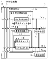
- FIG. 1 is a block diagram showing an embodiment of an electrical connection structure for a machine tool according to the present invention
- FIG. 4 is a block diagram showing another embodiment of the electrical connection structure of the machine tool according to the present invention
- It is a time chart figure of a transmission signal.
- FIG. 4 is a block diagram showing still another embodiment of the electrical connection structure of the machine tool according to the present invention
- an inrush current mitigation device 10 is attached to the working member 1 to suppress an inrush current generated when the working member 1 is replaced.
- the working member 1 can be replaced with the main body 2 of the machine tool via the connecting part 3.
- a robot hand can be given as a specific example of the working member 1, but the working member 1 is not limited to this. Also, since the structure of the connecting portion is well known, the description thereof will be omitted.
- the working member 1 and the main body side 2 are connected by power supply lines Vp, Vn and signal lines Dp, Dn.
- a control device for exchanging data necessary for controlling the working member 1 with the devices provided in the working member 1 via signal lines Dp and Dn is provided on the main body side 2 . It should be noted that illustration of the control device is omitted in FIG.
- the working member 1 is equipped with a drive device 4 required for operation and a communication device 5 for exchanging data required for its control. Although one drive device and one communication device are shown in FIG. 1 for the sake of convenience, there is no limit to the number of these devices, and as many devices as necessary may be connected.
- the driving device 4 is connected to the power lines Vp and Vn, and the electric power necessary for driving is supplied from the main body 2 of the machine tool.
- a control means provided in the driving device 4 is connected to the signal lines Dp and Dn, and driving is controlled based on control data transmitted from a control device provided on the main body side 2 .
- the communication device 5 is connected to the signal lines Dp and Dn, and exchanges data necessary for controlling the working member 1 with the main body 2 .
- a sensor (not shown) is connected to the communication device 5 for the purpose of acquiring data necessary for control, and a control device (not shown) is connected to the communication device 5 for the purpose of controlling other devices. It is connected.
- drive device 4 shown in FIG. 1 includes control means, a drive device without control means may be connected to the communication device 5 and controlled via the communication device 5 .
- the communication device 5 obtains the necessary power from the power supply superimposed on the transmission signal, but when sensors are connected, the power necessary for the operation of the sensors can be supplied via the power supply lines Vp and Vn. It can be a thing.
- the rush current mitigation device 10 includes a rush current mitigation resistor 11, an electronic switch 12, and a timer means 13, and is inserted into power lines Vp, Vn and signal lines Dp, Dn.
- the inrush current mitigation resistor 11 is inserted in the signal line Dp on the high potential side of the signal lines Dp and Dn and the power supply line Vp on the high potential side of the power supply lines Vp and Vn. may be inserted on the low potential side.
- the inrush current mitigation resistor 11 has the performance of suppressing the current instantaneously generated when the working member 1 is attached to the main body 2 within a range in which the protection circuit of the control device provided on the main body 2 does not operate. shall be In this embodiment, a 3 Watt resistor is employed.
- a bypass path 14 is provided in parallel with the inrush current mitigation resistor 11 at the portion where the inrush current mitigation resistor 11 is inserted in the signal line Dp and the power line Vp.
- An electronic switch 12 is inserted in the bypass path 14 .
- the electronic switch 12 is in a non-energized state when the working member 1 is removed from the main body of the working machine.
- the bypass route 14 is in a non-energized state.
- the electronic switch 12 is turned on. That is, the bypass route 14 is in the energization valid state. Therefore, it is preferable to have a low impedance and low heat generation when the bypass path 14 is in an energized state.
- the timer means 13 is connected to both the inrush current relaxation resistors 11 inserted in the signal line Dp and the power supply line Vp, and the signal lines Dp and Dn on the body side 2 of the inrush current relaxation resistor 11 inserted in the signal line Dp. It is Then, when the working member 1 is connected to the main body 2 and the potentials of the signal lines Dp and Dn reach a predetermined threshold value, the electronic switch 12 is turned on at the timing when a preset time has elapsed. The energized state is set, and the bypass route 14 is set to the energized enabled state. It should be noted that the timer means 13 of this embodiment is set with a time for charging the capacitance of the communication device 5 .
- the electronic switch 12 is in a non-energized state and the bypass path 14 is in a non-energized state in the working member 1 before being attached to the main body 2 of the machine tool, forming a high potential side. Since the inrush current mitigation resistors 11 inserted in the power line Vp and the signal line Dp are in the energized state, the inrush current generated when the working member 1 is attached is suppressed via the inrush current mitigation resistors 11. be.
- the timer means 13 turns on the electronic switch 12 at the timing when the preset time for charging the capacitance of the communication device 5 has passed. Since the energized state is set and the bypass path 14 is in the energized disabled state, power consumption and transmission signal attenuation due to the inrush current mitigation resistor 11 do not occur.
- the charging time of the electrostatic capacity is set in consideration of the device equipment provided in the working member 1, and is stored in the non-volatile memory provided in the timer means 13.
- the starting point for measuring the elapsed time in the timer means 13 is when the potentials of the signal lines Dp and Dn reach a predetermined threshold value. good. In that case, the timer means 13 will be connected to the power lines Vp and Vn.
- the timing at which the bypass path 14 is disabled is the timing at which the electrostatic capacity of the communication device 5 is charged. There is no limit as long as there is no timing. For example, appropriate timing may be determined based on the transmission signals sent through the signal lines Dp and Dn.
- FIG. 2 shows an embodiment in which the timing for setting the bypass path 14 to the non-energization state is determined based on transmission signals transmitted via the signal lines Dp and Dn.
- the same reference numerals are assigned to substantially the same parts as in the embodiment shown in FIG. 1, and the description thereof will be simplified or omitted.
- the autonomous energization control means 15 is connected to both ends of the inrush current mitigation resistor 11 inserted in the signal line Dp, and uses the signal lines Dp and Dn based on the transmission signals transmitted through the signal lines Dp and Dn.
- the electronic switch 12 is brought into the energized state and the bypass path 14 is brought into the energized state at the timing when no error occurs in the communication.
- the transmission signal is composed of a series of multiple pulse signals. As shown in FIG. 3, the pulse signal that constitutes the transmission signal has three predetermined potential levels (hereinafter referred to as high potential VH, medium potential VM, and low potential VL). Data values (logic data “1” and logic data “0”) depending on whether the clock signal changes across the threshold Vsck set between and the threshold Vsdt set between the middle potential VM and the low potential VL.
- one period is defined as the timing of the next fall of the clock signal, with reference to the timing at which the clock signal changes (falls) from the high potential VH to the middle potential VM.
- the timing of changing (rising) from the medium potential VM to the high potential VH may be used as a reference for one cycle, and the period from the rise of the clock signal to the next rise may be set as one cycle.
- a data value is defined by the length of the time (pulse width) from the timing of the falling edge of the clock signal to the next rising edge of the clock signal.
- the pulse width (3/4) t0 of the pulse signal forming the transmission signal represents logic data "1"
- the pulse width (1/4) t0 represents logic data "1”. It represents logical data "0”.
- the length is not limited and may be determined appropriately.
- the voltage signal that constitutes this transmission signal is a monitoring signal for transmitting data from the communication device 5 to the main body 2 of the machine tool.
- data smaller than the threshold Vsdt represents logic data "1"
- data greater than the threshold Vsdt represents logic data "0”.
- the voltage area higher than the medium potential VM forms the control data area
- the lower voltage area forms the monitoring data area
- each pulse signal is given an address address.
- the monitoring data area is provided over the entire area of the transmission signal. Monitoring data can be output.
- the last pulse of the series of pulse signals is an end bit that does not constitute the IO data area, and each terminal detects the end of the IO data area. Note that one frame of the transmission procedure in this embodiment is from the end bit to the next end bit.
- the autonomous energization control means 15 turns on the electronic switch 12 at the timing when the current value measured using the potential difference across the inrush current mitigation resistor 11 becomes smaller than a predetermined level in the end bit area, The bypass route 14 is brought into the energization valid state.
- the area of the transmission signal used for measuring the timing of energizing the electronic switch 12 is not limited to the end bit area, but is an area in which the potential does not change according to control data or monitoring data. is preferred. Specifically, an identification waveform that separates the frame of the transmission procedure and the next frame is preferable, and when the frame and the next frame are separated by a start signal provided at the beginning of the IO data area, the current value in the start signal area , the timing of turning on the electronic switch 12 may be measured.
- FIG. 4 shows an embodiment for timing the bypass path 14 to be in the energization valid state on the main body side 2 .
- substantially the same parts as those in the embodiment shown in FIGS. 1 and 2 are denoted by the same reference numerals, and the description thereof will be simplified or omitted.
- the energization control means 16 has a communication circuit, is connected to the signal lines Dp and Dn on the body side 2 of the inrush current mitigation resistor 11 inserted in the signal line Dp, and receives transmission signals.
- the energization control means 16 is also connected to both ends of the inrush current mitigation resistor 11 inserted in the signal line Dp, measures the current value, and transmits it to the main body 2 .
- the main body 2 Based on the current value information transmitted from the energization control means 16, the main body 2 acquires the timing to make the bypass path 14 energized and instructs the energization control means 16 to turn the electronic switch 12 into the energized state. Run. Then, the energization control means 16 having received this makes the electronic switch 12 energized and the bypass route 14 energized.
- Both the timer means 13 of the embodiment shown in FIG. 1 and the autonomous energization control means 15 of the embodiment shown in FIG. A function that enables communication with the side 2 may be provided.
- the main body 2 By making it possible for the main body 2 to adjust the set time of the timer means 13 and the threshold of the current value for measuring the timing of energizing the electronic switch 12 in the autonomous energization control means 15, the working member 1 can be It may also be used for optimization in subsequent mounting operations.
Landscapes
- Engineering & Computer Science (AREA)
- Robotics (AREA)
- Mechanical Engineering (AREA)
- Physics & Mathematics (AREA)
- General Physics & Mathematics (AREA)
- Automation & Control Theory (AREA)
- Human Computer Interaction (AREA)
- Manufacturing & Machinery (AREA)
- Numerical Control (AREA)
Priority Applications (2)
| Application Number | Priority Date | Filing Date | Title |
|---|---|---|---|
| JP2021576341A JPWO2022215265A1 (https=) | 2021-04-09 | 2021-04-09 | |
| PCT/JP2021/015068 WO2022215265A1 (ja) | 2021-04-09 | 2021-04-09 | 工作機械の電気的接続構造 |
Applications Claiming Priority (1)
| Application Number | Priority Date | Filing Date | Title |
|---|---|---|---|
| PCT/JP2021/015068 WO2022215265A1 (ja) | 2021-04-09 | 2021-04-09 | 工作機械の電気的接続構造 |
Publications (1)
| Publication Number | Publication Date |
|---|---|
| WO2022215265A1 true WO2022215265A1 (ja) | 2022-10-13 |
Family
ID=83545769
Family Applications (1)
| Application Number | Title | Priority Date | Filing Date |
|---|---|---|---|
| PCT/JP2021/015068 Ceased WO2022215265A1 (ja) | 2021-04-09 | 2021-04-09 | 工作機械の電気的接続構造 |
Country Status (2)
| Country | Link |
|---|---|
| JP (1) | JPWO2022215265A1 (https=) |
| WO (1) | WO2022215265A1 (https=) |
Citations (6)
| Publication number | Priority date | Publication date | Assignee | Title |
|---|---|---|---|---|
| JP2000354985A (ja) * | 1999-06-11 | 2000-12-26 | Denso Corp | 移動ロボット |
| US20050231874A1 (en) * | 2004-04-15 | 2005-10-20 | Hussein Hakam D | Inrush current controller |
| JP2007089243A (ja) * | 2005-09-20 | 2007-04-05 | Yaskawa Electric Corp | モータ制御システム |
| JP2016538813A (ja) * | 2013-11-26 | 2016-12-08 | キーメッド(メディカル アンド インダストリアル イクイプメント) リミテッド | 突入電流制限装置 |
| JP2019204746A (ja) * | 2018-05-25 | 2019-11-28 | 三菱電機株式会社 | 照明制御システム |
| JP2020182344A (ja) * | 2019-04-26 | 2020-11-05 | 三菱電機エンジニアリング株式会社 | 電源装置 |
Family Cites Families (2)
| Publication number | Priority date | Publication date | Assignee | Title |
|---|---|---|---|---|
| JP2008207294A (ja) * | 2007-02-27 | 2008-09-11 | Kondo Seisakusho:Kk | 自動工具交換装置 |
| JP2020145809A (ja) * | 2019-03-05 | 2020-09-10 | ファナック株式会社 | 電力変換装置 |
-
2021
- 2021-04-09 WO PCT/JP2021/015068 patent/WO2022215265A1/ja not_active Ceased
- 2021-04-09 JP JP2021576341A patent/JPWO2022215265A1/ja active Pending
Patent Citations (6)
| Publication number | Priority date | Publication date | Assignee | Title |
|---|---|---|---|---|
| JP2000354985A (ja) * | 1999-06-11 | 2000-12-26 | Denso Corp | 移動ロボット |
| US20050231874A1 (en) * | 2004-04-15 | 2005-10-20 | Hussein Hakam D | Inrush current controller |
| JP2007089243A (ja) * | 2005-09-20 | 2007-04-05 | Yaskawa Electric Corp | モータ制御システム |
| JP2016538813A (ja) * | 2013-11-26 | 2016-12-08 | キーメッド(メディカル アンド インダストリアル イクイプメント) リミテッド | 突入電流制限装置 |
| JP2019204746A (ja) * | 2018-05-25 | 2019-11-28 | 三菱電機株式会社 | 照明制御システム |
| JP2020182344A (ja) * | 2019-04-26 | 2020-11-05 | 三菱電機エンジニアリング株式会社 | 電源装置 |
Also Published As
| Publication number | Publication date |
|---|---|
| JPWO2022215265A1 (https=) | 2022-10-13 |
Similar Documents
| Publication | Publication Date | Title |
|---|---|---|
| CN110653822B (zh) | 工业机器人电弧微爆与切削复合加工设备及其控制方法 | |
| US20210209051A1 (en) | Bus subscriber and method for operating a bus subscriber | |
| JP5264788B2 (ja) | 放電加工装置 | |
| KR20150126387A (ko) | 반도체 장치 | |
| US8566631B2 (en) | Serially shutting down extension units to time extend power to CPU from charging backup supply | |
| JP7363955B2 (ja) | 給電制御装置、給電制御方法及びコンピュータプログラム | |
| WO2022215265A1 (ja) | 工作機械の電気的接続構造 | |
| JP3008848B2 (ja) | 電源装置 | |
| JP4682916B2 (ja) | 通信システム及び通信装置 | |
| TW201427214A (zh) | 電源供應器之保護電路 | |
| CN112332513A (zh) | 一种电子设备的电力控制方法及电子设备 | |
| US11729017B2 (en) | Load drive system | |
| EP1353271A2 (en) | Controller with fail-safe function | |
| JP6127856B2 (ja) | 電池監視装置 | |
| JP7552489B2 (ja) | 給電制御システム及び処理方法 | |
| JP2017005585A (ja) | 電子装置 | |
| JP2006282093A (ja) | 空調装置 | |
| JP4572711B2 (ja) | 電源システム | |
| JP6698447B2 (ja) | パワー半導体モジュールおよびパワーエレクトロニクス機器 | |
| JP5150188B2 (ja) | バックゲート切替回路、充電制御装置、電子機器 | |
| JP2000335047A (ja) | 画像形成装置 | |
| JP4777120B2 (ja) | アブソリュートエンコーダ用バックアップ電源 | |
| JP4244971B2 (ja) | ロボット制御装置 | |
| JP2007292691A (ja) | アブソリュートエンコーダ用バックアップ電源 | |
| CN113949039A (zh) | 电机热保护装置及其操作方法 |
Legal Events
| Date | Code | Title | Description |
|---|---|---|---|
| ENP | Entry into the national phase |
Ref document number: 2021576341 Country of ref document: JP Kind code of ref document: A |
|
| 121 | Ep: the epo has been informed by wipo that ep was designated in this application |
Ref document number: 21936068 Country of ref document: EP Kind code of ref document: A1 |
|
| NENP | Non-entry into the national phase |
Ref country code: DE |
|
| 122 | Ep: pct application non-entry in european phase |
Ref document number: 21936068 Country of ref document: EP Kind code of ref document: A1 |