WO2022210776A1 - ショベル - Google Patents
ショベル Download PDFInfo
- Publication number
- WO2022210776A1 WO2022210776A1 PCT/JP2022/015675 JP2022015675W WO2022210776A1 WO 2022210776 A1 WO2022210776 A1 WO 2022210776A1 JP 2022015675 W JP2022015675 W JP 2022015675W WO 2022210776 A1 WO2022210776 A1 WO 2022210776A1
- Authority
- WO
- WIPO (PCT)
- Prior art keywords
- hydraulic
- travel
- pump
- traveling
- amount
- Prior art date
- Legal status (The legal status is an assumption and is not a legal conclusion. Google has not performed a legal analysis and makes no representation as to the accuracy of the status listed.)
- Ceased
Links
Images








Classifications
-
- E—FIXED CONSTRUCTIONS
- E02—HYDRAULIC ENGINEERING; FOUNDATIONS; SOIL SHIFTING
- E02F—DREDGING; SOIL-SHIFTING
- E02F9/00—Component parts of dredgers or soil-shifting machines, not restricted to one of the kinds covered by groups E02F3/00 - E02F7/00
- E02F9/20—Drives; Control devices
- E02F9/22—Hydraulic or pneumatic drives
- E02F9/225—Control of steering, e.g. for hydraulic motors driving the vehicle tracks
-
- E—FIXED CONSTRUCTIONS
- E02—HYDRAULIC ENGINEERING; FOUNDATIONS; SOIL SHIFTING
- E02F—DREDGING; SOIL-SHIFTING
- E02F9/00—Component parts of dredgers or soil-shifting machines, not restricted to one of the kinds covered by groups E02F3/00 - E02F7/00
- E02F9/20—Drives; Control devices
- E02F9/22—Hydraulic or pneumatic drives
- E02F9/2253—Controlling the travelling speed of vehicles, e.g. adjusting travelling speed according to implement loads, control of hydrostatic transmission
-
- B—PERFORMING OPERATIONS; TRANSPORTING
- B62—LAND VEHICLES FOR TRAVELLING OTHERWISE THAN ON RAILS
- B62D—MOTOR VEHICLES; TRAILERS
- B62D11/00—Steering non-deflectable wheels; Steering endless tracks or the like
- B62D11/02—Steering non-deflectable wheels; Steering endless tracks or the like by differentially driving ground-engaging elements on opposite vehicle sides
- B62D11/04—Steering non-deflectable wheels; Steering endless tracks or the like by differentially driving ground-engaging elements on opposite vehicle sides by means of separate power sources
-
- E—FIXED CONSTRUCTIONS
- E02—HYDRAULIC ENGINEERING; FOUNDATIONS; SOIL SHIFTING
- E02F—DREDGING; SOIL-SHIFTING
- E02F9/00—Component parts of dredgers or soil-shifting machines, not restricted to one of the kinds covered by groups E02F3/00 - E02F7/00
- E02F9/02—Travelling-gear, e.g. associated with slewing gears
-
- E—FIXED CONSTRUCTIONS
- E02—HYDRAULIC ENGINEERING; FOUNDATIONS; SOIL SHIFTING
- E02F—DREDGING; SOIL-SHIFTING
- E02F9/00—Component parts of dredgers or soil-shifting machines, not restricted to one of the kinds covered by groups E02F3/00 - E02F7/00
- E02F9/20—Drives; Control devices
- E02F9/2004—Control mechanisms, e.g. control levers
-
- E—FIXED CONSTRUCTIONS
- E02—HYDRAULIC ENGINEERING; FOUNDATIONS; SOIL SHIFTING
- E02F—DREDGING; SOIL-SHIFTING
- E02F9/00—Component parts of dredgers or soil-shifting machines, not restricted to one of the kinds covered by groups E02F3/00 - E02F7/00
- E02F9/20—Drives; Control devices
- E02F9/2025—Particular purposes of control systems not otherwise provided for
-
- E—FIXED CONSTRUCTIONS
- E02—HYDRAULIC ENGINEERING; FOUNDATIONS; SOIL SHIFTING
- E02F—DREDGING; SOIL-SHIFTING
- E02F9/00—Component parts of dredgers or soil-shifting machines, not restricted to one of the kinds covered by groups E02F3/00 - E02F7/00
- E02F9/20—Drives; Control devices
- E02F9/22—Hydraulic or pneumatic drives
- E02F9/2221—Control of flow rate; Load sensing arrangements
- E02F9/2225—Control of flow rate; Load sensing arrangements using pressure-compensating valves
- E02F9/2228—Control of flow rate; Load sensing arrangements using pressure-compensating valves including an electronic controller
-
- E—FIXED CONSTRUCTIONS
- E02—HYDRAULIC ENGINEERING; FOUNDATIONS; SOIL SHIFTING
- E02F—DREDGING; SOIL-SHIFTING
- E02F9/00—Component parts of dredgers or soil-shifting machines, not restricted to one of the kinds covered by groups E02F3/00 - E02F7/00
- E02F9/20—Drives; Control devices
- E02F9/22—Hydraulic or pneumatic drives
- E02F9/2221—Control of flow rate; Load sensing arrangements
- E02F9/2232—Control of flow rate; Load sensing arrangements using one or more variable displacement pumps
- E02F9/2235—Control of flow rate; Load sensing arrangements using one or more variable displacement pumps including an electronic controller
-
- E—FIXED CONSTRUCTIONS
- E02—HYDRAULIC ENGINEERING; FOUNDATIONS; SOIL SHIFTING
- E02F—DREDGING; SOIL-SHIFTING
- E02F9/00—Component parts of dredgers or soil-shifting machines, not restricted to one of the kinds covered by groups E02F3/00 - E02F7/00
- E02F9/20—Drives; Control devices
- E02F9/22—Hydraulic or pneumatic drives
- E02F9/2278—Hydraulic circuits
- E02F9/2285—Pilot-operated systems
-
- E—FIXED CONSTRUCTIONS
- E02—HYDRAULIC ENGINEERING; FOUNDATIONS; SOIL SHIFTING
- E02F—DREDGING; SOIL-SHIFTING
- E02F9/00—Component parts of dredgers or soil-shifting machines, not restricted to one of the kinds covered by groups E02F3/00 - E02F7/00
- E02F9/20—Drives; Control devices
- E02F9/22—Hydraulic or pneumatic drives
- E02F9/2278—Hydraulic circuits
- E02F9/2296—Systems with a variable displacement pump
-
- F—MECHANICAL ENGINEERING; LIGHTING; HEATING; WEAPONS; BLASTING
- F16—ENGINEERING ELEMENTS AND UNITS; GENERAL MEASURES FOR PRODUCING AND MAINTAINING EFFECTIVE FUNCTIONING OF MACHINES OR INSTALLATIONS; THERMAL INSULATION IN GENERAL
- F16H—GEARING
- F16H61/00—Control functions within control units of change-speed- or reversing-gearings for conveying rotary motion ; Control of exclusively fluid gearing, friction gearing, gearings with endless flexible members or other particular types of gearing
- F16H61/38—Control of exclusively fluid gearing
- F16H61/40—Control of exclusively fluid gearing hydrostatic
-
- B—PERFORMING OPERATIONS; TRANSPORTING
- B60—VEHICLES IN GENERAL
- B60Y—INDEXING SCHEME RELATING TO ASPECTS CROSS-CUTTING VEHICLE TECHNOLOGY
- B60Y2200/00—Type of vehicle
- B60Y2200/40—Special vehicles
- B60Y2200/41—Construction vehicles, e.g. graders, excavators
- B60Y2200/412—Excavators
-
- E—FIXED CONSTRUCTIONS
- E02—HYDRAULIC ENGINEERING; FOUNDATIONS; SOIL SHIFTING
- E02F—DREDGING; SOIL-SHIFTING
- E02F9/00—Component parts of dredgers or soil-shifting machines, not restricted to one of the kinds covered by groups E02F3/00 - E02F7/00
- E02F9/20—Drives; Control devices
- E02F9/2025—Particular purposes of control systems not otherwise provided for
- E02F9/205—Remotely operated machines, e.g. unmanned vehicles
-
- E—FIXED CONSTRUCTIONS
- E02—HYDRAULIC ENGINEERING; FOUNDATIONS; SOIL SHIFTING
- E02F—DREDGING; SOIL-SHIFTING
- E02F9/00—Component parts of dredgers or soil-shifting machines, not restricted to one of the kinds covered by groups E02F3/00 - E02F7/00
- E02F9/20—Drives; Control devices
- E02F9/22—Hydraulic or pneumatic drives
- E02F9/2278—Hydraulic circuits
- E02F9/2282—Systems using center bypass type changeover valves
-
- E—FIXED CONSTRUCTIONS
- E02—HYDRAULIC ENGINEERING; FOUNDATIONS; SOIL SHIFTING
- E02F—DREDGING; SOIL-SHIFTING
- E02F9/00—Component parts of dredgers or soil-shifting machines, not restricted to one of the kinds covered by groups E02F3/00 - E02F7/00
- E02F9/20—Drives; Control devices
- E02F9/22—Hydraulic or pneumatic drives
- E02F9/2278—Hydraulic circuits
- E02F9/2292—Systems with two or more pumps
Definitions
- This disclosure relates to excavators.
- Patent Document 1 An excavator equipped with a traveling hydraulic motor is conventionally known (see Patent Document 1).
- Patent Document 1 does not disclose a method of controlling the traveling hydraulic motor when the shovel is turned. Therefore, there is a possibility that the shovel described above cannot smoothly turn.
- An excavator includes a lower traveling body including a crawler, an upper revolving body rotatably mounted on the lower traveling body, a traveling hydraulic motor that drives the crawler, and the traveling hydraulic motor. a travel operation device that supplies hydraulic oil to the travel hydraulic motor; and detection means that detects an operation state of the travel operation device, and the hydraulic pressure is detected according to a detection result of the operation state. To suppress fluctuations in the flow rate of hydraulic oil discharged by a pump.
- the excavator mentioned above can move smoothly.
- FIG. 1 is a side view of a shovel according to an embodiment of the present disclosure
- FIG. Figure 2 is a top view of the shovel of Figure 1
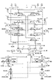
- 2 is a diagram showing a configuration example of a hydraulic system mounted on the excavator of FIG. 1
- FIG. 4 is a flowchart of driving support processing
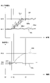
- FIG. 4 is a diagram showing an example of temporal transitions of a pump flow rate Q and an operation pressure Pi in a traveling independent operation state
- FIG. 10 is a diagram showing another example of temporal transitions of the pump flow rate Q and the operation pressure Pi in the traveling independent operation state
- FIG. 10 is a diagram showing still another example of the temporal transition of the pump flow rate Q and the operation pressure Pi in the traveling independent operation state; It is a top view of the crawler which turns leftward. It is a figure which shows the structural example of the basic system of the working machine which concerns on this embodiment.
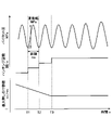
- FIG. 2 is a schematic diagram showing a configuration example of a hydraulic system mounted on the excavator of FIG. 1; It is a figure explaining hunting and correspondence information. It is a figure explaining hunting and correspondence information.
- 4 is a flowchart for explaining the operation of the shovel; It is a figure explaining the effect of this embodiment. It is a figure explaining the effect of this embodiment. It is a figure which shows the structural example of an electric operation system.
- FIGS. 1 is a side view of the shovel 100
- FIG. 2 is a top view of the shovel 100.
- the undercarriage 1 of the excavator 100 includes a crawler 1C.
- the crawler 1 ⁇ /b>C is driven by a traveling hydraulic motor 2 ⁇ /b>M as a traveling actuator mounted on the lower traveling body 1 .
- the crawler 1C includes a left crawler 1CL and a right crawler 1CR.
- the left crawler 1CL is driven by a left traveling hydraulic motor 2ML
- the right crawler 1CR is driven by a right traveling hydraulic motor 2MR.
- An upper revolving body 3 is rotatably mounted on the lower traveling body 1 via a revolving mechanism 2 .
- the revolving mechanism 2 is driven by a revolving hydraulic motor 2A as a revolving actuator mounted on the upper revolving body 3 .
- the turning actuator may be a turning motor generator as an electric actuator.
- a boom 4 is attached to the upper revolving body 3 .
- An arm 5 is attached to the tip of the boom 4, and a bucket 6 is attached to the tip of the arm 5 as an end attachment.
- the boom 4, the arm 5 and the bucket 6 constitute an excavation attachment which is an example of the attachment AT.
- a boom 4 is driven by a boom cylinder 7
- an arm 5 is driven by an arm cylinder 8
- a bucket 6 is driven by a bucket cylinder 9 .
- the boom cylinder 7, arm cylinder 8 and bucket cylinder 9 constitute an attachment actuator.
- the boom 4 is supported so as to be vertically rotatable with respect to the upper revolving body 3 .
- a boom angle sensor S1 is attached to the boom 4 .
- the boom angle sensor S ⁇ b>1 can detect a boom angle ⁇ b>1 that is the rotation angle of the boom 4 .
- the boom angle ⁇ 1 is, for example, the angle of elevation from the lowest state of the boom 4 . Therefore, the boom angle ⁇ 1 becomes maximum when the boom 4 is raised to the maximum.
- the arm 5 is rotatably supported with respect to the boom 4.
- An arm angle sensor S2 is attached to the arm 5. As shown in FIG.
- the arm angle sensor S2 can detect an arm angle ⁇ 2 that is the rotation angle of the arm 5 .
- the arm angle ⁇ 2 is, for example, the opening angle of the arm 5 from the most closed state. Therefore, the arm angle ⁇ 2 becomes maximum when the arm 5 is opened most.
- the bucket 6 is rotatably supported with respect to the arm 5.
- a bucket angle sensor S3 is attached to the bucket 6 .
- Bucket angle sensor S3 can detect bucket angle ⁇ 3, which is the rotation angle of bucket 6 .
- the bucket angle ⁇ 3 is the opening angle of the bucket 6 from the most closed state. Therefore, the bucket angle ⁇ 3 becomes maximum when the bucket 6 is opened most.
- each of the boom angle sensor S1, the arm angle sensor S2 and the bucket angle sensor S3 is composed of a combination of an acceleration sensor and a gyro sensor. However, it may be composed only of the acceleration sensor. Also, the boom angle sensor S1 may be a stroke sensor attached to the boom cylinder 7, or may be a rotary encoder, potentiometer, inertial measurement device, or the like. The same applies to the arm angle sensor S2 and the bucket angle sensor S3.
- a cabin 10 as an operator's cab is provided in the upper swing body 3, and a power source such as an engine 11 is mounted.
- a space recognition device 70, an orientation detection device 71, a positioning device 73, a body tilt sensor S4, a turning angular velocity sensor S5, and the like are attached to the upper swing body 3.
- an operation device 26 Inside the cabin 10, an operation device 26, a controller 30, an information input device 72, a display device D1, an audio output device D2, and the like are provided.
- the side of the upper rotating body 3 to which the attachment AT is attached is referred to as the front, and the side to which the counterweight is attached is referred to as the rear.
- the space recognition device 70 is configured to recognize objects existing in the three-dimensional space around the shovel 100. Further, the space recognition device 70 is configured to calculate the distance from the space recognition device 70 or the excavator 100 to the recognized object.
- the space recognition device 70 is, for example, an ultrasonic sensor, a millimeter wave radar, a monocular camera, a stereo camera, a LIDAR, a range image sensor, an infrared sensor, or the like.
- the space recognition device 70 is a LIDAR, and is configured to emit multiple laser beams in multiple directions, receive the reflected light, and calculate the distance and direction of the object from the reflected light. ing.
- the space recognition device 70 includes a front sensor 70F attached to the front end of the upper surface of the cabin 10, a rear sensor 70B attached to the rear end of the upper surface of the upper revolving structure 3, and a left end of the upper surface of the upper revolving structure 3. and a right sensor 70R attached to the right end of the upper surface of the upper swing body 3 .
- An upper sensor that recognizes an object existing in the space above the upper swing body 3 may be attached to the excavator 100 .
- the space recognition device 70 may be configured to capture an image of the surroundings of the shovel 100.
- the space recognition device 70 is, for example, a monocular camera having an imaging device such as a CCD or CMOS, and outputs the captured image to the display device D1.
- the space recognition device 70 may be configured to detect a predetermined object within a predetermined area set around the excavator 100 . That is, the space recognition device 70 may be configured to be able to identify at least one of the type, position, shape, and the like of an object. For example, the space recognition device 70 may be configured to be able to distinguish between humans and objects other than humans. Furthermore, the space recognition device 70 may be configured to identify the type of terrain around the excavator 100 . Terrain types are, for example, holes, slopes, or rivers. Furthermore, the space recognition device 70 may be configured to identify the type of obstacle. Types of obstacles are, for example, electric wires, utility poles, people, animals, vehicles, work equipment, construction machines, buildings, fences, and the like.
- the space recognition device 70 may be configured to identify the type or size of the dump truck as the vehicle. Furthermore, the space recognition device 70 detects a person by recognizing a helmet, safety vest, work clothes, or the like, or by recognizing a predetermined mark or the like on a helmet, safety vest, work clothes, or the like. It may be configured as Furthermore, the space recognition device 70 may be configured to recognize road conditions. Specifically, the space recognition device 70 may be configured, for example, to identify the type of object present on the road surface. Types of objects present on the road surface are, for example, cigarettes, cans, PET bottles, stones, and the like.
- the orientation detection device 71 is configured to detect information regarding the relative relationship between the orientation of the upper rotating body 3 and the orientation of the lower traveling body 1 .
- the orientation detection device 71 may be composed of, for example, a combination of a geomagnetic sensor attached to the lower traveling body 1 and a geomagnetic sensor attached to the upper rotating body 3 .
- the orientation detection device 71 may be configured by a combination of a GNSS receiver attached to the lower traveling body 1 and a GNSS receiver attached to the upper swing body 3 .
- the orientation detection device 71 may be a rotary encoder, a rotary position sensor, or the like.
- the orientation detection device 71 may be configured by a resolver.
- the orientation detection device 71 may be attached to, for example, a center joint provided in association with the revolving mechanism 2 that achieves relative rotation between the lower traveling body 1 and the upper revolving body 3 .
- the orientation detection device 71 may be composed of a camera attached to the upper revolving body 3 .
- the orientation detection device 71 performs known image processing on the image (input image) captured by the camera attached to the upper rotating body 3 to detect the image of the lower traveling body 1 included in the input image.
- the orientation detection device 71 identifies the longitudinal direction of the lower traveling body 1 by detecting the image of the lower traveling body 1 using a known image recognition technique. Then, the angle formed between the direction of the longitudinal axis of the upper revolving body 3 and the longitudinal direction of the lower traveling body 1 is derived.
- the direction of the longitudinal axis of the upper rotating body 3 is derived from the mounting position of the camera.
- orientation detection device 71 can identify the longitudinal direction of the lower traveling body 1 by detecting the image of the crawler 1C.
- orientation detection device 71 may be integrated into controller 30 .
- the information input device 72 is configured so that the excavator operator can input information to the controller 30 .
- the information input device 72 is a switch panel installed close to the display section of the display device D1.
- the information input device 72 may be a touch panel arranged on the display portion of the display device D1, or may be a voice input device such as a microphone arranged in the cabin 10 .
- the information input device 72 may be a communication device. In this case, the operator can input information to the controller 30 via a communication terminal such as a smart phone.
- the positioning device 73 is configured to measure the current position.
- the positioning device 73 is a GNSS receiver, detects the position of the upper swing structure 3 and outputs the detected value to the controller 30 .
- the positioning device 73 may be a GNSS compass. In this case, the positioning device 73 can detect the position and orientation of the upper swing body 3 .
- the fuselage tilt sensor S4 detects the tilt of the upper revolving structure 3 with respect to a predetermined plane.
- the fuselage tilt sensor S4 is an acceleration sensor that detects the tilt angle about the longitudinal axis and the tilt angle about the lateral axis of the upper swing structure 3 with respect to the horizontal plane.
- the longitudinal axis and the lateral axis of the upper swing body 3 are orthogonal to each other and pass through a shovel center point, which is one point on the swing axis of the shovel 100 .
- the turning angular velocity sensor S5 detects the turning angular velocity of the upper turning body 3. In this embodiment, it is a gyro sensor. It may be a resolver, a rotary encoder, or the like. The turning angular velocity sensor S5 may detect turning velocity. The turning speed may be calculated from the turning angular velocity.
- At least one of the boom angle sensor S1, the arm angle sensor S2, the bucket angle sensor S3, the body tilt sensor S4, and the turning angular velocity sensor S5 is hereinafter also referred to as an attitude detection device.
- the attitude of the attachment AT is detected, for example, based on outputs from the boom angle sensor S1, the arm angle sensor S2, and the bucket angle sensor S3.
- the display device D1 is a device that displays information.
- the display device D1 is a liquid crystal display installed inside the cabin 10 .
- the display device D1 may be a display of a communication terminal such as a smart phone.
- the audio output device D2 is a device that outputs audio.
- the voice output device D2 includes at least one of a device that outputs voice toward the operator inside the cabin 10 and a device that outputs voice toward the worker outside the cabin 10 .
- a speaker attached to the communication terminal may be used.
- the operating device 26 is a device used by the operator to operate the actuator.
- the controller 30 is a control device for controlling the excavator 100 .
- the controller 30 is configured by a computer including a CPU, RAM, NVRAM, ROM, and the like. Then, the controller 30 reads a program corresponding to each function from the ROM, loads it into the RAM, and causes the CPU to execute the corresponding process.
- Each function includes, for example, a machine guidance function that guides the manual operation of the excavator 100 by the operator, and supports the manual operation of the excavator 100 by the operator or causes the excavator 100 to operate automatically or autonomously. Including machine control functions such as
- FIG. 3 is a diagram showing a configuration example of a hydraulic system mounted on the excavator 100.
- FIG. 3 shows the mechanical driveline, hydraulic lines, pilot lines and electrical control system in double, solid, dashed and dotted lines respectively.
- the hydraulic system of the excavator 100 mainly includes an engine 11, a pump regulator 13, a main pump 14, a control pump 15, a control valve unit 17, an operating device 26, a discharge pressure sensor 28, an operating pressure sensor 29, a controller 30 and the like.
- the hydraulic system is configured so that hydraulic oil can be circulated from the main pump 14 driven by the engine 11 to the hydraulic oil tank through the center bypass line 40 or parallel line 42.
- the engine 11 is a drive source for the shovel 100.
- the engine 11 is, for example, a diesel engine that operates to maintain a predetermined number of revolutions.
- An output shaft of the engine 11 is connected to input shafts of the main pump 14 and the control pump 15 .
- the main pump 14 is configured to supply hydraulic oil to the control valve unit 17 via a hydraulic oil line.
- the main pump 14 is a swash plate type variable displacement hydraulic pump.
- the pump regulator 13 is configured to be able to control the discharge amount of the main pump 14 .
- the pump regulator 13 controls the discharge amount of the main pump 14 by adjusting the tilt angle of the swash plate of the main pump 14 according to the control command from the controller 30 .
- the control pump 15 is an example of a pilot pressure generating device, and is configured to supply hydraulic fluid to hydraulic control equipment including the operating device 26 via a pilot line.
- the control pump 15 is a fixed displacement hydraulic pump.
- the pilot pressure generator may be implemented by the main pump 14 . That is, the main pump 14 has a function of supplying hydraulic fluid to the control valve unit 17 via the hydraulic fluid line, and also a function of supplying hydraulic fluid to various hydraulic control devices including the operating device 26 via the pilot line. may be In this case, the control pump 15 may be omitted.
- the control valve unit 17 is a hydraulic control device that controls the hydraulic system in the excavator 100.
- the control valve unit 17 includes control valves 171-176.
- Control valve 172 includes control valve 172L and control valve 172R
- control valve 175 includes control valve 175L and control valve 175R
- control valve 176 includes control valve 176L and control valve 176R.
- the control valve unit 17 is configured to selectively supply hydraulic fluid discharged from the main pump 14 to one or more hydraulic actuators through control valves 171-176.
- the control valves 171 to 176 for example, control the flow rate of hydraulic fluid flowing from the main pump 14 to the hydraulic actuator and the flow rate of hydraulic fluid flowing from the hydraulic actuator to the hydraulic fluid tank.
- Hydraulic actuators include a boom cylinder 7, an arm cylinder 8, a bucket cylinder 9, a left travel hydraulic motor 2ML, a right travel hydraulic motor 2MR, and a swing hydraulic motor 2A.
- the operating device 26 is a device used by the operator to operate the actuator.
- the operating device 26 includes, for example, an operating lever and an operating pedal.
- the actuators include at least one of hydraulic actuators and electric actuators.
- the operation device 26 is configured to supply the hydraulic oil discharged by the control pump 15 to the pilot port of the corresponding control valve in the control valve unit 17 via the pilot line.
- the pressure (pilot pressure) of hydraulic fluid supplied to each of the pilot ports is a pressure corresponding to the operation direction and amount of operation of the operating device 26 corresponding to each of the hydraulic actuators.
- the operating device 26 may be of an electric control type instead of the pilot pressure type as described above.
- the control valve in the control valve unit 17 may be an electromagnetic solenoid spool valve.
- the discharge pressure sensor 28 is configured to detect the discharge pressure of the main pump 14, which is an example of circuit pressure.
- the circuit pressure is the pressure of hydraulic fluid in the hydraulic circuit mounted on the excavator 100 .
- the discharge pressure sensor 28 outputs the detected value to the controller 30 .
- the operation pressure sensor 29 is an example of detection means for detecting the operation state of the operation device, and is configured to detect the content of the operation of the operation device 26 by the operator.
- the operation pressure sensor 29 detects the operation direction and the operation amount of the operation device 26 corresponding to each actuator in the form of pressure (operation pressure), and outputs the detected value to the controller 30 .
- the content of the operation of the operating device 26 may be detected using a sensor other than the operating pressure sensor.
- the main pump 14 includes a left main pump 14L and a right main pump 14R.
- the left main pump 14L circulates the hydraulic oil to the hydraulic oil tank through the left center bypass pipe 40L or the left parallel pipe 42L
- the right main pump 14R circulates the right center bypass pipe 40R or the right parallel pipe 42R. to circulate hydraulic oil to the hydraulic oil tank.
- the left center bypass line 40L is a hydraulic oil line passing through control valves 172L, 173, 175L and 176L arranged in the control valve unit 17.
- the right center bypass line 40R is a hydraulic fluid line passing through control valves 171, 172R, 174, 175R and 176R arranged in the control valve unit 17.
- the control valve 171 is a spool valve that functions as a straight travel valve.
- the control valve 171 is configured to supply the hydraulic oil from the left main pump 14L to the left traveling hydraulic motor 2ML and the right traveling hydraulic motor 2MR in order to improve the straightness of the lower traveling body 1. You can switch the flow. Specifically, when the traveling hydraulic motor 2M and any other hydraulic actuator are operated simultaneously, the control valve 171 causes the left main pump 14L to operate both the left traveling hydraulic motor 2ML and the right traveling hydraulic motor 2MR. It is switched so that it can supply oil. On the other hand, when the traveling hydraulic motor 2M is operated and none of the other hydraulic actuators are operated, the control valve 171 causes the left main pump 14L to supply hydraulic fluid to the left traveling hydraulic motor 2ML. and the right main pump 14R is switched so that it can supply hydraulic oil to the right travel hydraulic motor 2MR.
- the control valve 172L controls the flow of hydraulic fluid in order to supply the hydraulic fluid discharged by the left main pump 14L to the left traveling hydraulic motor 2ML and to discharge the hydraulic fluid discharged by the left traveling hydraulic motor 2ML to the hydraulic fluid tank. It is a switching spool valve.
- the control valve 172R supplies hydraulic fluid discharged by the right main pump 14R to the right traveling hydraulic motor 2MR, and controls the flow of hydraulic fluid to discharge the hydraulic fluid discharged by the right traveling hydraulic motor 2MR to the hydraulic fluid tank. It is a switching spool valve.
- the control valve 173 supplies the hydraulic oil discharged by the left main pump 14L to the swing hydraulic motor 2A and discharges the hydraulic oil discharged by the swing hydraulic motor 2A to the hydraulic oil tank. valve.
- the control valve 174 is a spool valve that switches the flow of hydraulic oil to supply the hydraulic oil discharged by the right main pump 14R to the bucket cylinder 9 and to discharge the hydraulic oil in the bucket cylinder 9 to the hydraulic oil tank. .
- the control valve 175L is a spool valve that switches the flow of hydraulic oil in order to supply the hydraulic oil discharged by the left main pump 14L to the boom cylinder 7.
- the control valve 175R is a spool valve that switches the flow of hydraulic oil to supply the hydraulic oil discharged from the right main pump 14R to the boom cylinder 7 and to discharge the hydraulic oil in the boom cylinder 7 to the hydraulic oil tank. .
- the control valve 176L is a spool valve that switches the flow of hydraulic fluid to supply the hydraulic fluid discharged by the left main pump 14L to the arm cylinder 8 and to discharge the hydraulic fluid in the arm cylinder 8 to the hydraulic fluid tank. .
- the control valve 176R is a spool valve that switches the flow of hydraulic fluid to supply the hydraulic fluid discharged from the right main pump 14R to the arm cylinder 8 and to discharge the hydraulic fluid in the arm cylinder 8 to the hydraulic fluid tank. .
- the left parallel pipeline 42L is a hydraulic oil line parallel to the left center bypass pipeline 40L.
- the left parallel pipeline 42L can supply hydraulic fluid to more downstream control valves when the flow of hydraulic fluid through the left center bypass pipeline 40L is restricted or blocked by any of the control valves 172L, 173, 175L.
- the right parallel pipeline 42R is a hydraulic oil line parallel to the right center bypass pipeline 40R.
- the right parallel pipeline 42R can supply hydraulic fluid to more downstream control valves when the flow of hydraulic fluid through the right center bypass pipeline 40R is restricted or blocked by any of the control valves 172R, 174, 175R. .
- the pump regulator 13 includes a left pump regulator 13L and a right pump regulator 13R.
- the left pump regulator 13L controls the discharge amount of the left main pump 14L by adjusting the tilt angle of the swash plate of the left main pump 14L according to the discharge pressure of the left main pump 14L. Specifically, for example, the left pump regulator 13L adjusts the swash plate tilt angle of the left main pump 14L according to an increase in the discharge pressure of the left main pump 14L to reduce the discharge amount.
- the operating device 26 includes a left operating lever 26L and a right operating lever 26R as attachment operating devices, and a travel lever 26D as a travel operating device.
- a travel lever 26D as a travel operation device includes a left travel lever 26DL as a left travel operation device and a right travel lever 26DR as a right travel operation device.
- the left operation lever 26L as an attachment operation device is used for turning operation and operation of the arm 5.
- the control pressure corresponding to the amount of lever operation is introduced into the pilot port of the control valve 176 using hydraulic oil discharged from the control pump 15 .
- the hydraulic fluid discharged from the control pump 15 is used to introduce a control pressure corresponding to the amount of lever operation to the pilot port of the control valve 173 .
- the left operation lever 26L when the left operation lever 26L is operated in the arm closing direction, it introduces hydraulic fluid into the right pilot port of the control valve 176L and introduces hydraulic fluid into the left pilot port of the control valve 176R. . Further, when the left operating lever 26L is operated in the arm opening direction, it introduces hydraulic fluid into the left pilot port of the control valve 176L and introduces hydraulic fluid into the right pilot port of the control valve 176R.
- hydraulic oil is introduced into the left pilot port of the control valve 173, and when it is operated in the right turning direction, the right pilot port of the control valve 173 is introduced. Hydraulic oil is introduced into
- the right operating lever 26R as an attachment operating device is used for operating the boom 4 and the bucket 6.
- the control pressure corresponding to the amount of lever operation is introduced into the pilot port of the control valve 175 using hydraulic oil discharged from the control pump 15 .
- hydraulic oil discharged from the control pump 15 is used to introduce a control pressure corresponding to the amount of lever operation to the pilot port of the control valve 174 .
- hydraulic fluid is introduced into the left pilot port of the control valve 175R.
- hydraulic fluid is introduced into the right pilot port of the control valve 175L and introduces hydraulic fluid into the left pilot port of the control valve 175R.
- hydraulic oil is introduced into the right pilot port of the control valve 174, and when it is operated in the bucket opening direction, the hydraulic oil is introduced into the left pilot port of the control valve 174. Introduce hydraulic oil.
- the travel lever 26D is an example of a travel operation device, and is used to operate the crawler 1C.
- a left travel lever 26DL which is an example of a left travel operation device, is used to operate the left crawler 1CL. It may be configured to interlock with a left travel pedal, which is another example of a left travel operation device.
- the hydraulic oil discharged by the control pump 15 is used to introduce a control pressure corresponding to the amount of lever operation to the pilot port of the control valve 172L.
- a right travel lever 26DR which is an example of a right travel operation device, is used to operate the right crawler 1CR.
- It may be configured to interlock with a right travel pedal, which is another example of a right travel operation device.
- a right travel pedal which is another example of a right travel operation device.
- the discharge pressure sensor 28 includes a discharge pressure sensor 28L and a discharge pressure sensor 28R.
- the discharge pressure sensor 28L detects the discharge pressure of the left main pump 14L and outputs the detected value to the controller 30 . The same applies to the discharge pressure sensor 28R.
- the operation pressure sensors 29 include operation pressure sensors 29LA, 29LB, 29RA, 29RB, 29DL and 29DR.
- the operation pressure sensor 29LA detects the content of the operator's operation of the left operation lever 26L in the front-rear direction in the form of pressure, and outputs the detected value to the controller 30.
- FIG. The details of the operation are, for example, the lever operation direction, lever operation amount (lever operation angle), and the like.
- the operation pressure sensor 29LB detects, in the form of pressure, the content of the operator's operation of the left operation lever 26L in the horizontal direction, and outputs the detected value to the controller 30.
- the operation pressure sensor 29RA detects the content of the operator's operation of the right operation lever 26R in the front-rear direction in the form of pressure, and outputs the detected value to the controller 30.
- the operation pressure sensor 29 RB detects, in the form of pressure, the details of the operator's operation of the right operation lever 26 R in the horizontal direction, and outputs the detected value to the controller 30 .
- the operation pressure sensor 29DL is an example of a detection means for detecting the operation state of the travel operation device, detects in the form of pressure the content of the operator's operation of the left travel lever 26DL in the longitudinal direction, and outputs the detected value to the controller.
- the operation pressure sensor 29DR is an example of detecting means for detecting the operation state of the travel operation device, detects the content of the operator's operation of the right travel lever 26DR in the front-rear direction in the form of pressure, and outputs the detected value to the controller. 30.
- the controller 30 receives the output of the operating pressure sensor 29, outputs a control command to the pump regulator 13 as necessary, and changes the discharge amount of the main pump 14.
- the controller 30 also receives the output of a control pressure sensor 19 provided upstream of the throttle 18 and outputs a control command to the pump regulator 13 as necessary to change the discharge amount of the main pump 14 .
- the throttle 18 includes a left throttle 18L and a right throttle 18R
- the control pressure sensor 19 includes a left control pressure sensor 19L and a right control pressure sensor 19R.
- a left throttle 18L is arranged between the most downstream control valve 176L and the hydraulic oil tank in the left center bypass pipe 40L. Therefore, the flow of hydraulic oil discharged from the left main pump 14L is restricted by the left throttle 18L.
- the left throttle 18L generates a control pressure for controlling the left pump regulator 13L.
- Control pressure is an example of circuit pressure.
- the left control pressure sensor 19L is a sensor for detecting this control pressure, and outputs the detected value to the controller 30.
- the controller 30 controls the discharge amount of the left main pump 14L by adjusting the tilt angle of the swash plate of the left main pump 14L according to this control pressure.
- the controller 30 decreases the discharge amount of the left main pump 14L as the control pressure increases, and increases the discharge amount of the left main pump 14L as the control pressure decreases.
- the discharge amount of the right main pump 14R is similarly controlled.
- the controller 30 increases the discharge amount of the left main pump 14L, circulates a sufficient amount of hydraulic oil to the hydraulic actuator to be operated, and ensures the driving of the hydraulic actuator to be operated. Note that the controller 30 similarly controls the discharge amount of the right main pump 14R.
- the hydraulic system of FIG. 3 can suppress wasteful energy consumption in the main pump 14 in the standby state. Wasteful energy consumption includes pumping loss caused by the hydraulic fluid discharged by the main pump 14 in the center bypass pipe 40 . Further, the hydraulic system of FIG. 3 can reliably supply necessary and sufficient working oil from the main pump 14 to the hydraulic actuator to be operated when the hydraulic actuator is to be operated.
- the hydraulic system shown in FIG. 3 is an example of a hydraulic system mounted on the excavator 100.
- the hydraulic system mounted on the excavator 100 is not limited to the hydraulic system using the negative control system as shown in FIG.
- the hydraulic system mounted on the excavator 100 may be a hydraulic system using a positive control system or a load sensing system.
- FIG. 4 is a flow chart of the driving support process.
- the controller 30 repeatedly executes the driving support process at a predetermined control cycle when the driving operation device is operated.
- the controller 30 is configured to execute travel assistance processing to assist the excavator 100 in turning.
- the curving includes, for example, moving the lower traveling body 1 forward by varying the forward speed of the left crawler 1CL and the forward speed of the right crawler 1CR. That is, it includes moving the lower traveling body 1 forward with different rotational speeds of the left traveling hydraulic motor 2ML and the right traveling hydraulic motor 2MR.
- the forward speed of the left crawler 1CL is higher than the forward speed of the right crawler 1CR, the excavator 100 turns to the right.
- the left crawler 1CL is also called an outer crawler
- the right crawler 1CR is also called an inner crawler.
- the excavator 100 turns to the left.
- the left crawler 1CL is also called an inner crawler
- the right crawler 1CR is also called an outer crawler. Note that if the forward speed of the left crawler 1CL and the forward speed of the right crawler 1CR are the same, the shovel 100 travels straight.
- the operator makes the operation amount of the left travel lever 26DL in the forward direction smaller than the operation amount of the right travel lever 26DR in the forward direction.
- the operator may change only the amount of operation of the left travel lever 26DL or only the amount of operation of the right travel lever 26DR. You can change it.
- the excavator 100 may not be able to turn leftward smoothly. be. That is, there are cases where the travel locus of the crawler 1C ends up being different from the desired travel locus. This is because the condition of the road surface is likely to change suddenly at the work site.
- the condition of the road surface includes, for example, whether the earth and sand forming the road surface is clay or sand, whether it is dry or wet, whether it is covered with snow, whether it is uneven or not, whether it is uneven, whether it is an upward slope or a downward slope. and so on.
- the slippage of the left crawler 1CL worsens for example, when the coefficient of friction of the ground with which the left crawler 1CL is in contact increases
- the running load of the right crawler 1CR during forward movement increases, and the forward speed of the right crawler 1CR decreases. Therefore, the excavator 100 cannot smoothly turn to the left.
- the left crawler 1CL slides better (for example, when the friction coefficient of the ground with which the left crawler 1CL is in contact decreases), the left crawler 1CL drifts and the excavator 100 cannot smoothly turn to the left.
- the excavator 100 may not be able to smoothly turn to the left if the operator's operation is not appropriate. This is because, for example, when the operator suddenly reduces the amount of operation of the left traveling lever 26DL, the traveling load on the right crawler 1CR rapidly increases and the forward speed of the right crawler 1CR rapidly decreases.
- the reasons why the excavator 100 cannot be smoothly turned are that the discharge amount of the main pump 14 suddenly changes due to a sudden change in the traveling load, and that the displacement generated in response to the operation of the traveling operation device by the operator. It is considered that the value of the control command is not properly limited.
- the controller 30 executes a driving support process which will be described in detail below, so that the excavator 100 can be driven smoothly when the operator performs an operation for turning. To make it possible to run around a curve.
- the controller 30 determines whether or not the vehicle is in the independent travel operation state (step ST1).
- the independent travel operation state is one of the states of the excavator 100, and is a state in which only the travel operation device of the operation device 26 composed of the attachment operation device and the travel operation device is operated.
- the state of the excavator 100 includes, in addition to the traveling single operation state, a traveling combined operation state, a non-operation state, an attachment single operation state, and the like.
- the travel combined operation state is a state in which the attachment operation device and the travel operation device are operated at the same time.
- the non-operating state is a state in which neither the attachment operating device nor the travel operating device is operated.
- the attachment single operation state is a state in which only the attachment operation device is operated.
- the controller 30 determines whether or not the excavator 100 is in the independent travel operation state based on the output of the operation pressure sensor 29 .
- the controller 30 detects the operating state of the travel operating device, such as a sensor that detects the inclination of the travel lever 26D or a camera that captures an image of the operating state of the travel lever, based on the output of another device. It may be determined whether or not the state of the excavator 100 is the traveling independent operation state.
- the controller 30 determines that the vehicle is not in the traveling independent operation state (NO in step ST1), the controller 30 terminates the current traveling support process.
- the controller 30 detects the operation amount of the traveling operation device (step ST2).
- the controller 30 detects the amount of operation of the left travel lever 26DL based on the output of the operation pressure sensor 29DL, and detects the amount of operation of the right travel lever 26DR based on the output of the operation pressure sensor 29DR. .
- the traveling pedal is depressed.
- the controller 30 determines whether or not the left-right difference in the amount of operation is equal to or greater than a predetermined value (step ST3). This is for determining whether or not the vehicle is traveling in a curve (steering operation). In this embodiment, the controller 30 determines whether or not the difference between the amount of operation of the left travel lever 26DL and the amount of operation of the right travel lever 26DR is equal to or greater than a predetermined value.
- controller 30 determines that the left-right difference in the amount of operation is less than the predetermined value (NO in step ST3), the controller 30 terminates the current driving support process.
- step ST3 if it is determined that the difference between the left and right operation amounts is equal to or greater than the predetermined value (YES in step ST3), the controller 30 suppresses the amount of change in the pump flow rate command value within a predetermined range (step ST4).
- a pump flow rate command value is a command value that the controller 30 transmits to the pump regulator 13 .
- the pump flow rate command value includes a left pump flow rate command value for the left pump regulator 13L corresponding to the left main pump 14L and a right pump flow rate command value for the right pump regulator 13R corresponding to the right main pump 14R.
- the discharge amount of the main pump 14 is configured to increase as the pump flow rate command value increases.
- the predetermined range may be a pre-stored range or a dynamically derived range.
- one of a plurality of pre-stored ranges is selected based on at least one of the current state of the main pump 14 and the current states of the control valves 172L and 172R. be done.
- the predetermined range is selected from a plurality of pre-stored ranges based on at least one of the left-right difference in operation amount, circuit pressure, motor pressure, engine speed, and the like. .
- the content of selection of the predetermined range may be changed according to whether or not it is a sudden operation.
- the left-right difference in the amount of operation and whether or not the operation is sudden is derived based on the output of the operation pressure sensor 29, for example.
- the motor pressure is, for example, the pressure of hydraulic fluid flowing into the travel hydraulic motor 2M.
- the left motor pressure which is the pressure of the hydraulic fluid flowing into the left travel hydraulic motor 2ML, may be detected, for example, by a pressure sensor installed in a conduit connecting the control valve 172L and the left travel hydraulic motor.
- the same applies to the right motor pressure which is the pressure of hydraulic fluid flowing into the right travel hydraulic motor 2MR.
- the controller 30 suppresses the amount of change in the pump flow rate command value per unit time within a predetermined range. Even if it is operated, it is possible to prevent the discharge amount of the main pump 14 from excessively changing. That is, the controller 30 can gently change the discharge amount of the main pump 14 even when the traveling load suddenly changes or when the operator suddenly operates the traveling operation device. .
- the controller 30 can prevent the actual travel trajectory from excessively deviating from the travel trajectory envisioned by the operator, and can smoothly turn the excavator 100 .
- FIG. 5 shows an example of temporal transitions of the pump flow rate Q and the operating pressure Pi in the traveling independent operation state.
- the pump flow rate Q in the travel independent operation state includes the left pump flow rate QL, which is the discharge rate of the left main pump 14L that supplies hydraulic fluid to the left travel hydraulic motor 2ML, and the right pump flow rate QL that supplies hydraulic fluid to the right travel hydraulic motor 2MR. It includes the right pump flow rate QR, which is the discharge rate of the main pump 14R.
- the operation pressure Pi includes the left operation pressure PiL, which is the pilot pressure generated by the left travel lever 26DL (the pilot pressure acting on the pilot port of the control valve 172L), and the pilot pressure generated by the right travel lever 26DR (the control valve 172R, which is the pilot pressure acting on the pilot port of 172R).
- the upper diagram of FIG. 5 shows the temporal transition of the pump flow rate Q.
- the solid line in the upper part of FIG. 5 represents the temporal transition of the left pump flow rate QL when the driving support process is executed, and the dotted line is the temporal transition of the left pump flow rate QLa when the driving support process is not executed.
- represents 5 represents the temporal transition of the right pump flow rate QR when the driving support process is executed, and the dashed line represents the right pump flow rate QRa when the driving support process is not executed.
- the solid line in the lower diagram of FIG. 5 represents the temporal transition of the left operating pressure PiL for the left traveling lever 26DL, and the broken line in the lower diagram of FIG. 5 represents the temporal transition of the right operating pressure PiR for the right traveling lever 26DR.
- the operator causes the excavator 100 that is traveling straight to turn to the left, and then makes the excavator 100 go straight again.
- the operator sets the same amount of operation of the left travel lever 26DL and that of the right travel lever 26DR.
- both the left operating pressure PiL and the right operating pressure PiR are at the value P1
- both the left pump flow rate QL and the right pump flow rate QR are at the value Q1.
- the operator starts reducing the amount of operation of the left travel lever 26DL, and reduces the amount of operation of the left travel lever 26DL at a substantially constant rate until time t2.
- the left operation pressure PiL becomes the value Pt1 at the time t2, and becomes the value P2 at the time t3.
- the operator maintains the amount of operation of the right traveling lever 26DR. Therefore, the right operation pressure PiR is maintained at the value P1.
- the operator starts increasing the operation amount of the left travel lever 26DL, and increases the operation amount of the left travel lever 26DL at a substantially constant rate until time t5.
- the left operation pressure PiL returns to the value P1 at time t5. That is, the amount of operation of the left travel lever 26DL is the same as the amount of operation of the right travel lever 26DR.
- the operator maintains the amount of operation of the right traveling lever 26DR. Therefore, the right operation pressure PiR is maintained at the value P1.
- the controller 30 determines at time t2 that the difference between the amount of operation of the left travel lever 26DL and the amount of operation of the right travel lever 26DR is equal to or greater than a predetermined value
- the controller 30 issues a pump flow rate command as shown in step ST4 of FIG.
- the amount of change in value is suppressed within a predetermined range.
- the controller 30 controls the operation amount of the left travel lever 26DL and the right travel lever 26DR is determined to be a predetermined value or more.
- the controller 30 limits the left pump flow rate command value to limit the left pump flow rate QL within a predetermined range defined by an upper limit TL1 represented by a two-dot chain line and a lower limit BL1 represented by a two-dot chain line. is configured to As a result, the left pump flow rate QL becomes the value Q2 at time t3. The right pump flow rate QR remains at the value Q1. Note that the two-dot chain line only roughly represents temporal transitions of the values of the upper limit TL1 and the lower limit BL1, and does not represent accurate temporal transitions of the respective values.
- the predetermined range is the difference between the left pump flow rate command value used in the previous control cycle (hereinafter referred to as the "previous command value") and the left pump flow rate command value used in the current control cycle. is set so that the difference between them is equal to or less than a predetermined value.
- the controller 30 temporarily sets a left pump flow rate command value that is smaller than the previous command value and that differs from the previous command value by a predetermined value or more in response to, for example, a sudden change in the running load or a sudden change in the operation amount. Even if it is calculated, it can be dealt with appropriately.
- the controller 30 subtracts a predetermined value from the previous command value so that the difference between the previous command value and the left pump flow rate command value finally used in the current control cycle becomes a predetermined value. , is calculated as the left pump flow rate command value that is finally used in the current control cycle. That is, the controller 30 adopts a value corresponding to the lower limit BL1 of the predetermined range as the left pump flow rate command value finally used in the current control cycle.
- the controller 30 can appropriately handle a case in which a left pump flow rate command value larger than the previous command value, which is larger than the previous command value and which is equal to or greater than a predetermined value, can be handled appropriately by the controller 30 .
- the controller 30 adds a predetermined value to the previous command value so that the difference between the previous command value and the left pump flow rate command value finally used in the current control cycle becomes a predetermined value. , is calculated as the left pump flow rate command value that is finally used in the current control cycle. That is, the controller 30 adopts a value corresponding to the upper limit TL1 of the predetermined range as the left pump flow rate command value finally used in the current control cycle.
- the controller 30 changes the left pump flow rate QLa in the upper diagram of FIG. It is possible to realize the temporal transition of the left pump flow rate QL with small fluctuations as indicated by the solid line in .
- the controller 30 controls the time transition of the right pump flow rate QRa, which fluctuates greatly when the driving support process is not executed, as indicated by the dashed line in the upper diagram of FIG. It is possible to realize the temporal transition of the right pump flow rate QR with small fluctuations as indicated by the dashed line in . This is because, in the example shown in FIG. 5, fluctuations in the right pump flow rate QR are suppressed by suppressing fluctuations in the left pump flow rate QL.
- the controller 30 limits the right pump flow rate QR within the predetermined range. It is configured to limit the right pump flow rate command value as much as possible.
- the controller 30 controls the left pump to fall within a predetermined range defined by an upper limit TL2 indicated by a two-dot chain line and a lower limit BL2 indicated by a two-dot chain line. It is configured to limit the left pump flow rate command value in order to limit the flow rate QL.
- the two-dot chain line only roughly represents temporal transitions of the values of the upper limit TL2 and the lower limit BL2, and does not represent accurate temporal transitions of the respective values.
- the pump flow rate Q can be similarly applied to the temporal transition of .
- FIG. 6 shows an example of the temporal transition of the pump flow rate Q and the operating pressure Pi in the traveling independent operation state, and corresponds to FIG.
- the operator is performing an operation to turn the excavator 100, which is traveling straight ahead, to the left. Specifically, at time t0, the operator sets the same amount of operation of the left travel lever 26DL and that of the right travel lever 26DR. At this time, both the left operating pressure PiL and the right operating pressure PiR are at the value P11, and both the left pump flow rate QL and the right pump flow rate QR are at the value Q11.
- the operator starts increasing the amount of operation of the right travel lever 26DR, and increases the amount of operation of the right travel lever 26DR at a substantially constant rate until time t3.
- the right operation pressure PiR takes the value Pt2 at time t2 and takes the value P12 at time t3.
- the operator maintains the amount of operation of the left traveling lever 26DL. Therefore, the left operation pressure PiL is maintained at the value P11.
- the controller 30 determines at time t2 that the difference between the amount of operation of the left travel lever 26DL and the amount of operation of the right travel lever 26DR is equal to or greater than a predetermined value
- the controller 30 issues a pump flow rate command as shown in step ST4 in FIG.
- the amount of change in value is suppressed within a predetermined range.
- the controller 30 controls the operation amount of the left travel lever 26DL and the right travel lever 26DR is determined to be a predetermined value or more.
- the controller 30 limits the right pump flow rate command value to limit the right pump flow rate QR within a predetermined range defined by an upper limit TL3 represented by a two-dot chain line and a lower limit BL3 represented by a two-dot chain line. is configured to As a result, the right pump flow rate QR becomes the value Q12 at time t3. The left pump flow rate QL remains at the value Q11. Note that the two-dot chain line only roughly represents temporal transitions of the values of the upper limit TL3 and the lower limit BL3, and does not represent accurate temporal transitions of the respective values.
- the predetermined range is set such that the difference between the previous command value and the right pump flow rate command value used in the current control cycle is equal to or less than a predetermined value.
- the controller 30 can provisionally set the right pump flow rate command value larger than the previous command value, for example, in response to a sudden change in the running load or a sudden change in the operation amount, etc. Even if it is calculated, it can be dealt with appropriately.
- the controller 30 adds a predetermined value to the previous command value so that the difference between the previous command value and the right pump flow rate command value finally used in the current control cycle becomes a predetermined value. , is calculated as the right pump flow rate command value that is finally used in the current control cycle. That is, the controller 30 adopts a value corresponding to the upper limit TL3 of the predetermined range as the right pump flow rate command value finally used in the current control cycle.
- the controller 30 can appropriately handle a case in which the right pump flow rate command value, which is smaller than the previous command value and which has a difference from the previous command value equal to or greater than a predetermined value, is provisionally calculated.
- the controller 30 subtracts a predetermined value from the previous command value so that the difference between the previous command value and the right pump flow rate command value finally used in the current control cycle becomes a predetermined value. , is calculated as the right pump flow rate command value that is finally used in the current control cycle. That is, the controller 30 adopts a value corresponding to the lower limit BL3 of the predetermined range as the right pump flow rate command value finally used in the current control cycle.
- the controller 30 controls the flow rate QRa of the right pump in the upper part of FIG. It is possible to realize a temporal transition of the right pump flow rate QR with small fluctuations, as indicated by the dashed line in the figure.
- the controller 30 controls the time transition of the left pump flow rate QLa, which fluctuates greatly when the driving support process is not executed, as indicated by the dotted line in the upper diagram of FIG. It is possible to realize a temporal transition of the left pump flow rate QL with small fluctuations as indicated by the solid line. This is because, in the example shown in FIG. 6, fluctuations in the left pump flow rate QL are suppressed by suppressing fluctuations in the right pump flow rate QR.
- the controller 30 limits the left pump flow rate QL within the predetermined range. It is configured to limit the left pump flow rate command value as much as possible.
- the above description with reference to FIG. 6 relates to the temporal transition of the pump flow rate Q when the excavator 100 that is traveling straight makes a left turn.
- the same can be applied to the temporal transition of the pump flow rate Q when traveling straight. 6, the pump flow rate Q can be similarly applied to the temporal transition of .
- FIG. 7 shows an example of the temporal transition of the pump flow rate Q and the operating pressure Pi in the traveling independent operation state, and corresponds to FIG.
- the operator is performing an operation to turn the excavator 100, which is traveling straight ahead, to the left. Specifically, at time t0, the operator sets the same amount of operation of the left travel lever 26DL and that of the right travel lever 26DR. At this time, both the left operating pressure PiL and the right operating pressure PiR are at the value P21, and both the left pump flow rate QL and the right pump flow rate QR are at the value Q21.
- the operator starts reducing the amount of operation of the right travel lever 26DR, and reduces the amount of operation of the right travel lever 26DR at a substantially constant rate until time t3.
- the right operation pressure PiR takes the value Pt3 at time t2 and takes the value P22 at time t3.
- the operator starts reducing the amount of operation of the left travel lever 26DL, and reduces the amount of operation of the left travel lever 26DL at a substantially constant rate until time t3.
- the left operation pressure PiL becomes a value Pt4 smaller than the current right operation pressure PiR value Pt3 at time t2, and becomes a value P23 smaller than the current right operation pressure PiR value P22 at time t3.
- the controller 30 determines at time t2 that the difference between the amount of operation of the left travel lever 26DL and the amount of operation of the right travel lever 26DR is equal to or greater than a predetermined value
- the controller 30 issues a pump flow rate command as shown in step ST4 of FIG.
- the amount of change in value is suppressed within a predetermined range.
- the controller 30 controls the operation amount of the left travel lever 26DL and the right travel lever 26DR is determined to be a predetermined value or more.
- the controller 30 limits the right pump flow rate command value to limit the right pump flow rate QR within a predetermined range defined by an upper limit TL4 represented by a two-dot chain line and a lower limit BL4 represented by a two-dot chain line. is configured as Further, the controller 30 limits the left pump flow rate command value to limit the left pump flow rate QL within a predetermined range defined by an upper limit TL5 represented by a two-dot chain line and a lower limit BL5 represented by a two-dot chain line. is configured as As a result, the right pump flow rate QR becomes the value Q22 at the time t3, and the left pump flow rate QL becomes the value Q23 at the time t3.
- the two-dot chain line only schematically represents the temporal transition of each value of the upper limit TL4, the upper limit TL5, the lower limit BL4, and the lower limit BL5, and does not represent the accurate temporal transition of each value. .
- the predetermined range is set so that the difference between the previous command value and the pump flow rate command value used in the current control cycle is equal to or less than a predetermined value.
- the controller 30 temporarily calculates a pump flow rate command value that is greater than the previous command value and that differs from the previous command value by a predetermined value or more in response to, for example, a sudden change in the running load or a sudden change in the operation amount. can be dealt with appropriately.
- the controller 30 adds a predetermined value to the previous command value so that the difference between the previous command value and the pump flow rate command value finally used in the current control cycle becomes a predetermined value. It is calculated as the pump flow rate command value that is finally used in the current control cycle.
- the controller 30 can appropriately handle a case in which a pump flow rate command value that is smaller than the previous command value, which is smaller than the previous command value and whose difference from the previous command value is greater than or equal to a predetermined value, is provisionally calculated.
- the controller 30 subtracts a predetermined value from the previous command value so that the difference between the previous command value and the pump flow rate command value finally used in the current control cycle becomes a predetermined value. It is calculated as the pump flow rate command value that is finally used in the current control cycle.
- the controller 30 controls the flow rate QRa of the right pump in the upper part of FIG. It is possible to realize a temporal transition of the right pump flow rate QR with small fluctuations, as indicated by the dashed line in the figure.
- the controller 30 controls the time transition of the left pump flow rate QLa, which fluctuates greatly when the driving support process is not executed, as indicated by the dotted line in the upper diagram of FIG. It is possible to realize a temporal transition of the left pump flow rate QL with small fluctuations as indicated by the solid line.
- the above description with reference to FIG. 7 relates to the time transition of the pump flow rate Q when the excavator 100 that is traveling straight makes a left turn. The same can be applied to the temporal course of the pump flow rate Q at time. 7, the pump flow rate Q can be similarly applied to the temporal transition of .
- the controller 30 outputs a final It is possible to suppress sudden changes in the pump flow rate command value output to. Therefore, the controller 30 can cause the excavator 100 to smoothly travel in a curve, for example, when the operator performs an operation for traveling in a curve.
- the controller 30 can be operated even when the operator suddenly operates the travel lever 26D to correct the travel locus. , a sudden change in the pump flow rate Q can be suppressed. Therefore, the controller 30 can allow the operator to smoothly correct the traveling locus of the excavator 100 .
- the controller 30 may be configured so as to be able to suppress fluctuations in the pilot pressure associated with the travel lever 26D when it is determined that the travel independent operation state is established. This is to prevent the pump flow rate Q from suddenly changing when the traveling lever 26D is suddenly operated.
- the controller 30 controls the solenoid valve to control the pressure when the travel lever 26D is suddenly operated. Fluctuations in the pilot pressure may be suppressed.
- FIG. 8 is a top view of the crawler 1C curving leftward.
- illustration of members other than the crawler 1C, which constitutes the shovel 100 is omitted for clarity.
- a dashed line PL indicates the travel locus of the left crawler 1CL when the travel assistance process is performed, and a dashed line PR indicates the travel locus of the right crawler 1CR when the travel assistance process is performed.
- a dashed-dotted line PLa indicates the travel locus of the left crawler 1CL when the travel assistance process is not performed, and a dashed-dotted line PRa indicates the travel locus of the right crawler 1CR when the travel assistance process is not performed.
- the details of the operation on the travel lever 26D when the travel assistance process is executed are the same as the details of the operation on the travel lever 26D when the travel assistance process is not performed.
- the crawler 1C turns to the left while meandering when the driving support process is not executed, but draws a smooth arc when the driving support process is executed. Turn left.
- the controller 30 can prevent the excavator 100 from being unnecessarily increased due to meandering or the like by causing the excavator 100 to curve leftward in a smooth arc. As a result, the controller 30 can obtain an energy saving effect such as a reduction in fuel consumption.
- the controller 30 prevents the fluctuation of the discharge amount of the main pump 14 from becoming excessively large during traveling on a curve, thereby reducing the travel load caused by inappropriate operation of the travel lever 26D by the operator. can be prevented from being repeatedly increased and decreased. In this respect as well, the controller 30 can obtain an energy saving effect.
- the excavator 100 includes the lower traveling body 1 including the crawler 1C, the upper revolving body 3 rotatably mounted on the lower traveling body 1, and the traveling hydraulic pressure that drives the crawler 1C. Detection for detecting the operation state of the motor 2M, the travel lever 26D as a travel operation device corresponding to the travel hydraulic motor 2M, the main pump 14 as a hydraulic pump that supplies hydraulic oil to the travel hydraulic motor 2M, and the travel operation device means and The excavator 100 is configured to suppress fluctuations in the flow rate of the hydraulic oil discharged by the main pump 14 according to the detection result of the operating state.
- the main pump 14 may be an electronically controlled variable displacement hydraulic pump. With this configuration, the excavator 100 can smoothly turn.
- the crawler 1C has the left crawler 1CL and the right crawler 1CR.
- the travel lever 26D as a travel operation device has a left travel lever 26DL as a left travel operation device corresponding to the left crawler 1CL and a right travel lever 26DR as a right travel operation device corresponding to the right crawler 1CR.
- the excavator 100 determines that the lower traveling body 1 is making a turn, and the main pump 14 is operated. It may be configured to suppress fluctuations in the flow rate of the hydraulic oil to be discharged.
- the predetermined difference is, for example, when the operation amount of one of the left travel lever 26DL and the right travel lever 26DR is increased, when the operation amount of one of them is decreased, when the operation amount of both is increased, or when both are increased. Occurs when the operation amount is reduced.
- the excavator 100 suppresses the amount of change in the pump flow rate command value, which is the command value relating to the flow rate of the hydraulic oil discharged by the main pump 14, based on the pressure of the hydraulic fluid flowing through the hydraulic circuit or the operation amount of the travel lever 26D.
- the pump flow rate command value which is the command value relating to the flow rate of the hydraulic oil discharged by the main pump 14, based on the pressure of the hydraulic fluid flowing through the hydraulic circuit or the operation amount of the travel lever 26D.
- the driver's body When the driver operates the pedals, the driver's body is in an unstable state supported mainly by the buttocks. Therefore, if the aircraft shakes due to unevenness on the ground (road surface) or unexpected acceleration, the driver's body is shaken, and unintended operations such as depressing the pedals and releasing the pedals are repeated. Hunting may occur. In a conventional excavator, when hunting occurs in the operation amount, the pressure of the hydraulic oil discharged by the hydraulic pump fluctuates according to this hunting. As a result, the fuselage swings further, increasing the load on the driver.
- the excavator 100 includes a lower traveling body 1, an upper revolving body 3 that is rotatably mounted on the lower traveling body 1 via a turning mechanism 2, and an attachment AT.
- a boom 4, an arm 5, a bucket 6, and a cabin 10 are provided.
- the lower running body 1 (an example of a running body) includes a pair of left and right crawlers 1C, specifically, a left crawler 1CL and a right crawler 1CR, as described later.
- the lower traveling body 1 causes the excavator 100 to travel by hydraulically driving the left crawler 1CL and the right crawler 1CR by traveling hydraulic motors 2M (left traveling hydraulic motor 2ML and right traveling hydraulic motor 2MR).
- the upper revolving body 3 (an example of a revolving body) revolves relative to the lower traveling body 1 by being driven by a revolving hydraulic motor 2A.
- the boom 4 is pivotally attached to the center of the front portion of the upper rotating body 3 so as to be able to be raised.
- An arm 5 is pivotally attached to the tip of the boom 4 so as to be vertically rotatable.
- a bucket 6 is pivotally mounted so as to be vertically rotatable.
- the boom 4, arm 5, and bucket 6 are hydraulically driven by boom cylinders 7, arm cylinders 8, and bucket cylinders 9 as hydraulic actuators, respectively.
- the bucket 6 is an example of an end attachment, and depending on the type of work, other end attachments such as slope buckets, dredging buckets, and breakers may be attached to the tip of the arm 5 instead of the bucket 6. etc. may be attached.
- the cabin 10 is a driver's cab where an operator boards, and is mounted on the front left side of the upper revolving body 3 .
- the excavator 100 operates actuators according to the operation of an operator in the cabin 10 to operate operating elements (driven elements) such as the lower traveling body 1, the upper rotating body 3, the boom 4, the arm 5, and the bucket 6. drive.
- operating elements driven elements
- the excavator 100 is configured to be remotely operable by an operator of a predetermined external device (for example, a support device or a management device).
- a predetermined external device for example, a support device or a management device.
- the excavator 100 transmits image information (captured image) output by the space recognition device 70, which will be described later, to the external device.
- image information captured image
- Various information images displayed on the display device D1 of the excavator 100, which will be described later, may also be displayed on the display device D1 provided in the external device.
- the operator can remotely operate the excavator 100 while checking the contents displayed on the display device D1 provided in the external device, for example.
- the excavator 100 operates the actuators according to a remote control signal representing the details of remote control received from an external device, and operates the lower traveling body 1, the upper rotating body 3, the boom 4, the arm 5, and the bucket 6. may drive operational elements such as
- the display device D1 of the present embodiment is connected to the controller 30 (control unit), and under the control of the controller 30, is provided at a position within the cabin 10 that is easily visible to the seated driver, and displays various information images.
- the display device D1 is, for example, a liquid crystal display or an organic EL (Electroluminescence) display.
- the space recognition device 70 of this embodiment includes a front sensor 70F attached to the front end of the upper surface of the cabin 10, a rear sensor 70B attached to the rear end of the upper surface of the upper revolving structure 3, and a left end of the upper surface of the upper revolving structure 3.
- a left sensor 70L and a right sensor 70R attached to the right end of the upper surface of the upper swing body 3 are included.
- an upper recognition sensor that recognizes an object existing in the space above the upper revolving body 3 may be attached to the excavator 100 .
- the space recognition device 70 may be configured to detect objects existing around the excavator 100 .
- Objects are, for example, topographical shapes (slopes or holes, etc.), electric wires, utility poles, people, animals, vehicles, construction machinery, buildings, walls, helmets, safety vests, work clothes, or predetermined marks on helmets. .
- the space recognition device 70 may be configured to be able to identify at least one of the type, position, shape, and the like of an object.
- the space recognition device 70 may be configured to be able to distinguish between humans and objects other than humans.
- the space recognition device 70 may be configured to calculate the distance from the space recognition device 70 or the excavator 100 to the object recognized by the space recognition device 70 .
- the space recognition device 70 is, for example, an ultrasonic sensor, a millimeter wave radar, a monocular camera, a stereo camera, a LIDAR, a distance image sensor, an infrared sensor, or the like.
- the interior of the cabin 10 may be unmanned.
- the following description is based on the premise that the operator's operation includes at least one of the operation of the operating device 26 (see FIG. 9) by the driver of the cabin 10 and the remote operation of the external device by the driver.
- the excavator 100 may automatically operate the hydraulic actuator regardless of the details of the operator's operation.
- the excavator 100 has a function (hereinafter referred to as an "automatic operation function” or “ machine control function”).
- the automatic operation function includes a function (a so-called “semi-automatic operation function”) that automatically operates an operation element (hydraulic actuator) other than the operation target operation element (hydraulic actuator) according to the operation of the operation device 26 by the driver or remote control. ”) may be included.
- the automatic driving function includes a function that automatically operates at least a part of a plurality of driven elements (hydraulic actuators) on the premise that the driver does not operate the operation device 26 or remote control (so-called “fully automatic driving function”) ”) may be included.
- the automatic operation function includes the excavator 100 recognizing gestures of people such as workers around the excavator 100, and depending on the content of the recognized gesture, at least some of the plurality of driven elements (hydraulic actuators) (“gesture operation function”) may be included.
- the semi-automatic operation function, the fully automatic operation function, and the gesture operation function may include a mode in which the operation contents of the operation elements (hydraulic actuators) targeted for automatic operation are automatically determined according to predetermined rules.
- the excavator 100 autonomously makes various judgments, and according to the judgment results, the operation elements (hydraulic actuators) to be autonomously operated automatically. (so-called "autonomous operation function") may be included.
- FIG. 9 is a diagram showing a configuration example of a basic system of a work machine according to this embodiment.
- FIG. 9 the mechanical power transmission line, hydraulic oil line, pilot line, and electrical control line are indicated by double lines, solid lines, broken lines, and dashed lines, respectively. The same applies to FIG. 10 as well.
- the basic system of the excavator 100 mainly includes an engine 11, a pump regulator 13, a main pump 14, a control pump 15, a control valve unit 17, an operation device 26, an electromagnetic valve 27, a discharge pressure sensor 28, an operation pressure sensor 29, and a controller 30. , switch 31, switch 32, motor regulator 50, and the like.
- the engine 11 is a drive source for the shovel 100.
- the engine 11 is, for example, a diesel engine as an internal combustion engine that operates to maintain a predetermined number of revolutions.
- An output shaft of the engine 11 is connected to input shafts of the main pump 14 and the control pump 15 .
- the main pump 14 is a device for supplying hydraulic oil to the control valve unit 17 via a hydraulic oil line, and is, for example, a swash plate type variable displacement hydraulic pump.
- the pump regulator 13 is a device for controlling the discharge amount of the main pump 14 .
- the pump regulator 13 controls the discharge amount of the main pump 14 by adjusting the tilt angle of the swash plate of the main pump 14 according to the discharge pressure of the main pump 14, the command current from the controller 30, and the like. do.
- the control pump 15 is a device that supplies hydraulic oil to various hydraulic control devices including the operation device 26, and is, for example, a fixed displacement hydraulic pump.
- the control valve unit 17 is a hydraulic control device that controls the hydraulic system in the excavator 100.
- control valve unit 17 includes a plurality of control valves that control the flow of hydraulic oil discharged by the main pump 14 .
- the control valve unit 17 selectively supplies hydraulic fluid discharged from the main pump 14 to one or more hydraulic actuators through these control valves. These control valves control the flow rate of hydraulic fluid flowing from the main pump 14 to the hydraulic actuator and the flow rate of hydraulic fluid flowing from the hydraulic actuator to the hydraulic fluid tank.
- Hydraulic actuators include a boom cylinder 7, an arm cylinder 8, a bucket cylinder 9, a travel hydraulic motor 2M, and a swing hydraulic motor 2A.
- the traveling hydraulic motor 2M includes a left traveling hydraulic motor 2ML and a right traveling hydraulic motor 2MR.
- the operating device 26 is a device used by the driver to operate the hydraulic actuator.
- the operation device 26 is hydraulic, and supplies the hydraulic oil discharged by the control pump 15 to the pilot ports of the control valves corresponding to the respective hydraulic actuators via pilot lines.
- the operating device 26 of the present embodiment is mainly a pedal operated by the driver's foot.
- the operating device 26 may include a lever that is manually operated by the driver.
- pilot pressure The pressure of the hydraulic fluid supplied to each of the pilot ports (hereinafter referred to as "pilot pressure") depends on the operation direction and amount of operation of the lever or pedal that constitutes the operation device 26 corresponding to each of the hydraulic actuators. pressure.
- the operating device 26 may be electric.
- the solenoid valve 27 is arranged in the conduit C0 between the control pump 15 and the motor regulator 50.
- the electromagnetic valve 27 is an electromagnetic switching valve that switches between communication and blocking of the pipeline C0, and operates according to commands from the controller 30.
- the pressure reducing valve 33 is arranged in a pipeline between the control pump 15 and the operating device 26 and the solenoid valve 27 .
- the pressure reducing valve 33 reduces the pilot pressure and operates according to a command from the controller 30 .
- the discharge pressure sensor 28 is a sensor for detecting the discharge pressure of the main pump 14 and outputs the detected value to the controller 30 .
- the operating pressure sensor 29 detects the details of the driver's operation using the operating device 26 .
- the operation pressure sensor 29 is a pressure sensor that detects, in the form of pressure, the operation direction and operation amount of the pedals constituting the operation device 26 corresponding to each of the hydraulic actuators. 30.
- the details of the operation of the operation device 26 may be detected using the output of devices other than the pressure sensor, such as an operation angle sensor, acceleration sensor, angular velocity sensor, resolver, voltmeter, and ammeter. That is, the operation amount of the operation device 26 may be expressed not only by the operation pressure but also by the operation angle, the double integral value of the operation acceleration, the integral value of the operation angular velocity, the voltage value, the current value, and the like.
- the controller 30 is a control device for controlling the excavator 100 .
- the controller 30 is configured by a computer including, for example, a CPU, a volatile memory device, a nonvolatile memory device, and the like.
- the controller 30 causes the CPU to execute, for example, programs corresponding to various functional elements described later.
- the controller 30 executes various processes, which will be described later, based on outputs from the discharge pressure sensor 28, the operating pressure sensor 29, the switch 31, and the like. Details of the functions of the controller 30 will be described later.
- the switch 31 is a switch for switching the operation mode (running mode) of the motor regulator 50 .
- the switch 31 is a software switch displayed on an in-vehicle display with a touch panel.
- the switch 31 may be a hardware switch installed inside the cabin 10 .
- the switch 32 is a switch for switching between an operation for raising the cabin 10 and an operation for lowering it.
- the switch 32 may be, for example, a hardware switch installed inside the cabin 10, and switches between raising and lowering the cabin 10 according to the operation. Moreover, in this embodiment, the position of the cabin 10 does not move when the switch 32 is not operated.
- the motor regulator 50 controls the motor capacity of the traveling hydraulic motor 2M.
- the motor regulator 50 includes a left motor regulator 50L and a right motor regulator 50R.
- the left motor regulator 50L controls the motor capacity of the left travel hydraulic motor 2ML by adjusting the swash plate tilt angle of the left travel hydraulic motor 2ML in accordance with the control pressure of hydraulic fluid supplied through the solenoid valve 27 .
- the left motor regulator 50L switches the tilt angle of the swash plate of the left travel hydraulic motor 2ML in two steps, thereby setting the motor capacity of the left travel hydraulic motor 2ML in two steps of a high rotation setting and a low rotation setting. can be switched.
- the low rotation setting is achieved by increasing the motor capacity.
- the left traveling hydraulic motor 2ML operates at low rotation and high torque.
- a high rotation setting is realized by reducing the motor volume.
- the left travel hydraulic motor 2ML operates at high rotation and low torque.
- the controller 30 of this embodiment has a hunting determining section 301 , a counting section 302 , a driving force changing section 303 and a storage section 304 .
- the hunting determination unit 301 determines whether hunting has occurred in the operation amount based on the change in the operation amount detected by the operation pressure sensor 29 . If the operation device 26 is of an electric type, it may be determined whether or not hunting has occurred in the operation amount based on changes in the operation angle.
- the hunting determination unit 301 determines that hunting has occurred when the operation amount detected by the operation pressure sensor 29 is detected to periodically rise and fall. The details of hunting will be described later.
- the counting unit 302 counts the number of times the hunting determination unit 301 determines that hunting has occurred in a predetermined period, and holds the count value. Also, the counting unit 302 resets the count value each time a predetermined period elapses.
- a predetermined period is a preset period.
- the driving force changing unit 303 changes the driving force of the traveling hydraulic motor 2M according to the number of times of hunting counted by the counting unit 302 in a predetermined period.
- the driving force changing unit 303 refers to the information stored in the storage unit 304 that associates the number of times hunting has occurred with the method of changing the driving force of the travel hydraulic motor 2M, and determines whether hunting occurs.
- the driving force is changed according to the number of times.
- information stored in the storage unit 304 may be expressed as association information.
- the driving force of the traveling hydraulic motor 2M in this embodiment is, in other words, the driving pressure of the traveling hydraulic motor 2M.
- the driving pressure of the traveling hydraulic motor 2M in this embodiment may be the maximum value of the discharge amount of the main pump 14, for example.
- the maximum value of the discharge amount of the main pump 14 is, in other words, the maximum displacement volume of the main pump 14 .
- the driving pressure of the traveling hydraulic motor 2M in this embodiment may be the driving pressure of the traveling hydraulic motor 2M.
- the driving pressure of the traveling hydraulic motor 2M is, in other words, the maximum displacement of the traveling hydraulic motor 2M, and is controlled by adjusting the tilt angle of the swash plate of the traveling hydraulic motor 2M with the motor regulator 50 .
- the driving force changing unit 303 of the present embodiment refers to the count value held by the counting unit 302 and the association information, and changes the discharge amount of the main pump 14 according to the number of times of hunting that occurred during a predetermined period. Decrease or increase the maximum value of In other words, the driving force changing unit 303 reduces or increases the maximum displacement of the main pump 14 or the traveling hydraulic motor 2M according to the number of times of hunting that occurs in a predetermined period. In this manner, the driving force changing unit 303 reduces or increases the maximum displacement volume of the main pump 14 or the traveling hydraulic motor 2M, thereby suppressing fluctuations in the pressure of the hydraulic oil discharged by the main pump 14.
- the driving force changing unit 303 controls the main pump 14 or the traveling hydraulic motor 2M according to the determination result of the hunting determination unit 301, it is not necessarily limited to this.
- an operating control valve proportional valve
- the driving force changing unit 303 is The operation control valve may be controlled according to the determination result of the determination unit 301 .
- the driving force changing section 303 may control the electromagnetic solenoid spool valve according to the determination result of the hunting determining section 301. In this manner, the driving force of the traveling hydraulic motor can be changed even by using an operation control valve, an electromagnetic solenoid type spool valve, or the like.
- Correlation information is stored in advance in the storage unit 304 of the present embodiment.
- the association information may be, for example, information indicating the discharge amount of the main pump 14 to be decreased or increased for one hunting.
- the association information may be, for example, information indicating the maximum displacement volume of the traveling hydraulic motor 2M to be decreased or increased for one hunting.
- association information may be a function that indicates the relationship between the number of times of hunting and the maximum discharge amount of the main pump 14 . Also, the association information may be a function indicating the relationship between the number of times of hunting and the maximum displacement volume of the traveling hydraulic motor 2M.
- FIG. 10 is a schematic diagram showing a configuration example of a hydraulic system mounted on the excavator of FIG.
- the hydraulic system of FIG. 10 has a left center bypass line 40L, a right center bypass line 40R, a left parallel line 42L, and a right parallel line 42R from a left main pump 14L and a right main pump 14R driven by the engine 11.
- the hydraulic oil is circulated to the hydraulic oil tank.
- a left main pump 14L and a right main pump 14R correspond to the main pump 14 in FIG.
- the left center bypass line 40L is a hydraulic oil line passing through control valves 172L, 177, 173, 175L, and 176L arranged in the control valve unit 17.
- the right center bypass line 40R is a hydraulic oil line passing through control valves 171, 172R, 174, 175R, and 176R arranged in the control valve unit 17.
- the control valve 172L controls the flow of hydraulic fluid in order to supply the hydraulic fluid discharged by the left main pump 14L to the left traveling hydraulic motor 2ML and to discharge the hydraulic fluid discharged by the left traveling hydraulic motor 2ML to the hydraulic fluid tank. It is a switching spool valve.
- the control valve 171 is a spool valve as a straight travel valve.
- the control valve 171 switches the flow of hydraulic fluid so that hydraulic fluid is supplied from the left main pump 14L to the left traveling hydraulic motor 2ML and the right traveling hydraulic motor 2MR in order to improve the straightness of the lower traveling body 1 .
- the left main pump 14L can supply hydraulic fluid to both the left traveling hydraulic motor 2ML and the right traveling hydraulic motor 2MR.
- the control valve 171 is switched to .
- the left main pump 14L can supply hydraulic fluid to the left travel hydraulic motor 2ML
- the right main pump 14R can supply hydraulic fluid to the right travel hydraulic motor 2MR.
- the control valve 171 is switched.
- the control valve 177 supplies the hydraulic fluid discharged by the left main pump 14L to the optional hydraulic actuator and discharges the hydraulic fluid discharged by the optional hydraulic actuator to the hydraulic fluid tank.
- An optional hydraulic actuator is, for example, a grapple open/close cylinder.
- the control valve 172R supplies hydraulic fluid discharged by the right main pump 14R to the right traveling hydraulic motor 2MR, and controls the flow of hydraulic fluid to discharge the hydraulic fluid discharged by the right traveling hydraulic motor 2MR to the hydraulic fluid tank. It is a switching spool valve.
- the control valve 173 supplies the hydraulic oil discharged by the left main pump 14L to the swing hydraulic motor 2A and discharges the hydraulic oil discharged by the swing hydraulic motor 2A to the hydraulic oil tank. valve.
- the control valve 174 is a spool valve for supplying the hydraulic oil discharged by the right main pump 14R to the bucket cylinder 9 and discharging the hydraulic oil in the bucket cylinder 9 to the hydraulic oil tank.
- the control valves 175L and 175R supply the hydraulic oil discharged from the left main pump 14L and the right main pump 14R to the boom cylinder 7, and discharge the hydraulic oil in the boom cylinder 7 to the hydraulic oil tank. It is a spool valve that switches the flow. In this embodiment, the control valve 175L operates only when the boom 4 is raised, and does not operate when the boom 4 is lowered.
- the control valves 175L and 175R supply the hydraulic fluid discharged from the left main pump 14L and the right main pump 14R to the arm cylinder 8, and discharge the hydraulic fluid in the arm cylinder 8 to the hydraulic fluid tank. It is a spool valve that switches the flow.
- the left parallel pipeline 42L is a hydraulic oil line parallel to the left center bypass pipeline 40L.
- the left parallel pipeline 42L supplies hydraulic fluid to more downstream control valves when the flow of hydraulic fluid passing through the left center bypass pipeline 40L is restricted or blocked by any of the control valves 172L, 177, 173, and 175L. can supply.
- the right parallel pipeline 42R is a hydraulic oil line parallel to the right center bypass pipeline 40R.
- the right parallel pipeline 42R can supply hydraulic fluid to more downstream control valves when the flow of hydraulic fluid through the right center bypass pipeline 40R is restricted or blocked by any of the control valves 172R, 174, 175R. .
- the left pump regulator 13L and the right pump regulator 13R adjust the swash plate tilt angles of the left main pump 14L and the right main pump 14R according to the discharge pressures of the left main pump 14L and the right main pump 14R. 14L, which controls the discharge amount of the right main pump 14R.
- a left pump regulator 13L and a right pump regulator 13R correspond to the pump regulator 13 in FIG.
- the left pump regulator 13L and the right pump regulator 13R adjust the tilt angle of the swash plate of the left main pump 14L and the right main pump 14R to discharge. reduce the amount. This is to prevent the absorption horsepower of the main pump 14 , which is represented by the product of the discharge pressure and the discharge amount, from exceeding the output horsepower of the engine 11 .
- the left traveling operating device 26PL and the right traveling operating device 26PR are examples of the operating device 26.
- the left travel operation device 26PL is a pedal device and is used to operate the left travel hydraulic motor 2ML.
- the left travel operation device 26PL utilizes hydraulic fluid discharged from the control pump 15 to apply a pilot pressure corresponding to the amount of operation to the pilot port of the control valve 172L.
- the left traveling operation device 26PL applies pilot pressure to the left pilot port of the control valve 172L when operated in the forward direction, and applies pilot pressure to the right pilot port of the control valve 172L when operated in the reverse direction. Apply pilot pressure.
- the left traveling operation device 26PL has lifting pins 91L and 92L that are fixed and supported by the floor plate and move up and down in conjunction with the rotation of the rotatable rotating body.
- the lift pins 91L and 92L are biased upward by springs or the like.
- the tip of the lifting pin 91L pushes down the remote control valve 93L
- the tip of the lifting pin 92L pushes down the remote control valve 94L.
- the right travel operation device 26PR is used to operate the right travel hydraulic motor 2MR.
- the right traveling operation device 26PR utilizes hydraulic fluid discharged from the control pump 15 to apply a pilot pressure corresponding to the amount of operation to the pilot port of the control valve 172R.
- the right travel operation device 26PR applies pilot pressure to the right pilot port of the control valve 172R when operated in the forward direction, and applies pilot pressure to the left pilot port of the control valve 172R when operated in the reverse direction. Apply pilot pressure to
- the right traveling operation device 26PR has lifting pins 91R and 92R that are fixed and supported by the floor plate and move up and down in conjunction with the rotation of the rotatable rotating body.
- the lift pins 91R and 92R are biased upward by springs or the like.
- the tip of the lifting pin 91R pushes down the remote control valve 93R
- the tip of the lifting pin 92R pushes down the remote control valve 94R.
- the solenoid valve 27 allows communication between the control pump 15 and the motor regulator 50 when receiving a communication command from the controller 30 .
- the motor regulator 50 operates in forced fixed mode.
- the solenoid valve 27 cuts off the communication between the control pump 15 and the motor regulator 50 when the communication command from the controller 30 is not received. In this case, the motor regulator 50 operates in variable mode.
- the pressure reducing valve 33 controls the stroke amount (movement amount) of the spool of each of the control valves 172L and 172R in accordance with a command from the controller 30.
- the pressure reducing valve 33 is not necessarily required when the flow reduction process is performed by the travel hydraulic motor 2M, the main pump 14, the engine 11, and the like.
- the discharge pressure sensors 28L and 28R are examples of the discharge pressure sensor 28 in FIG.
- the discharge pressure sensor 28L detects the discharge pressure of the left main pump 14L and outputs the detected value to the controller 30 .
- the discharge pressure sensor 28R detects the discharge pressure of the right main pump 14R and outputs the detected value to the controller 30 .
- the operation pressure sensors 29L and 29R are examples of the operation pressure sensor 29 in FIG. Specifically, the operation pressure sensors 29L and 29R are an example of detection means for detecting the operation state of the traveling operation device.
- the operation pressure sensor 29L detects the details of the driver's operation on the left traveling operation device 26PL in the form of pressure, and outputs the detected value to the controller 30.
- the operation pressure sensor 29 ⁇ /b>R detects the details of the driver's operation on the right traveling operation device 26 ⁇ /b>PR in the form of pressure, and outputs the detected value to the controller 30 .
- the operating devices 26 are not hydraulic pilot type for outputting pilot pressure, but electric signals (hereinafter referred to as "operation It may be an electric type that outputs a signal").
- operation It may be an electric type that outputs a signal.
- an electric signal (operation signal) from the operating device 26 is input to the controller 30, and the controller 30 controls each of the control valves 171 to 177 in the control valve unit 17 according to the input electric signal.
- various hydraulic actuators can be operated in accordance with the content of the operation performed on the operating device 26 .
- control valves 171 to 177 in the control valve unit 17 may be electromagnetic solenoid type spool valves driven by commands from the controller 30 .
- hydraulic control valves (hereinafter referred to as "operational control valves") that operate in response to electrical signals from the controller 30 are arranged.
- the operating control valve may be, for example, a proportional valve.
- the controller 30 controls the control valve for operation by an electric signal corresponding to the amount of operation (for example, the amount of lever operation) to increase the pilot pressure.
- each of the control valves 171 to 177 can be operated in accordance with the operation contents of the operating device 26.
- a boom operating lever, an arm operating lever, a bucket operating lever, and a turning operating lever are used to move the boom 4 up and down, open and close the arm 5, open and close the bucket 6, and move the upper swing body 3, respectively. It is an operating device for operating turning. Similar to the left traveling operation device 26PL, these operation devices use the hydraulic oil discharged from the control pump 15 to apply pilot pressure corresponding to the lever operation amount to either the left or right control valve corresponding to each hydraulic actuator. acting on the pilot port of Further, the details of the driver's operation on each of these operation devices are detected in the form of pressure by the corresponding operation pressure sensors, similar to the operation pressure sensor 29L, and the detected values are output to the controller 30.
- the left center bypass line 40L and the right center bypass line 40R are provided with left throttles 18L and right throttles 18R between the most downstream control valves 176L and 176R, respectively, and the hydraulic oil tank.
- the flow of hydraulic oil discharged from the left main pump 14L and the right main pump 14R is restricted by the left throttle 18L and the right throttle 18R.
- the left throttle 18L and the right throttle 18R generate control pressures for controlling the left pump regulator 13L and the right pump regulator 13R.
- the left control pressure sensor 19L and the right control pressure sensor 19R are sensors that detect the control pressure generated upstream of the left throttle 18L and the right throttle 18R. In this embodiment, the left control pressure sensor 19L and the right control pressure sensor 19R output the detected values to the controller 30 .
- the controller 30 outputs a command according to the control pressure to the left pump regulator 13L and the right pump regulator 13R.
- the left pump regulator 13L and the right pump regulator 13R control the discharge amounts of the left main pump 14L and the right main pump 14R by adjusting the swash plate tilt angles of the left main pump 14L and the right main pump 14R according to commands. do.
- the left pump regulator 13L and the right pump regulator 13R reduce the discharge amounts of the left main pump 14L and the right main pump 14R as the control pressure increases, and reduce the discharge amounts of the left main pump 14L and the right main pump 14R as the control pressure decreases. Increase the discharge amount of 14R.
- hydraulic fluid discharged from the left main pump 14L and the right main pump 14R passes through the left center bypass pipe 40L and the right center bypass pipe 40R, and reaches the left throttle 18L and the right throttle 18R. up to.
- the flow of hydraulic oil discharged from the left main pump 14L and the right main pump 14R increases the control pressure generated upstream of the left throttle 18L and the right throttle 18R.
- the left pump regulator 13L and the right pump regulator 13R reduce the discharge amounts of the left main pump 14L and the right main pump 14R to the minimum allowable discharge amount, and the discharged hydraulic oil is discharged through the left center bypass pipe 40L and the right center bypass line 40L. To suppress the pressure loss (pumping loss) when passing through the pipeline 40R.
- hydraulic fluid discharged from the left main pump 14L and the right main pump 14R flows into the operated hydraulic actuator via the control valve corresponding to the operated hydraulic actuator.
- the flow of hydraulic oil discharged from the left main pump 14L and the right main pump 14R reduces or eliminates the amount reaching the left throttle 18L and the right throttle 18R, and the control pressure generated upstream of the left throttle 18L and the right throttle 18R lower the
- the left pump regulator 13L and the right pump regulator 13R increase the discharge amounts of the left main pump 14L and the right main pump 14R, circulate a sufficient amount of hydraulic oil to the hydraulic actuator to be operated, and increase the flow rate of the hydraulic actuator to be operated. Ensure drive.
- the hydraulic system of FIG. 10 can suppress wasteful energy consumption in the left main pump 14L and the right main pump 14R when none of the hydraulic actuators is operated.
- Wasteful energy consumption includes pumping loss caused by hydraulic fluid discharged from the left main pump 14L and the right main pump 14R in the left center bypass line 40L and the right center bypass line 40R.
- FIGS. 11A and 11B are diagrams for explaining hunting and correspondence information.
- FIG. 11A shows the relationship between changes in the amount of operation detected by the operation pressure sensor 29, the number of times of hunting, and the driving force of the traveling hydraulic motor 2M.
- the operation amount detected by the operation pressure sensor 29 is assumed to be the pilot pressure
- the driving force of the travel hydraulic motor 2M is assumed to be the maximum displacement of the main pump 14 .
- the period from time T1 to time T2 is a predetermined interval, and the fluctuation width of the pilot pressure during this period is a predetermined value. counted. That is, in the present embodiment, the amplitude (fluctuation width) of the waveform indicating the pilot pressure is a predetermined value, and one cycle is counted as one hunting when the predetermined interval is one cycle.
- the maximum displacement volume of the main pump 14 is set to a value corresponding to the number of times of hunting.
- FIG. 11B is a diagram showing an example of the association information stored in the storage unit 304.
- FIG. 11B as the correspondence information, the number of times of hunting in a predetermined period and the maximum displacement volume of the main pump 14 are associated with each other.
- the predetermined period is 1 second
- the count unit 302 holds the number of times of hunting detected by the hunting determination unit 301 for each second as a count value. Therefore, the count value of counting section 302 is reset every second.
- the driving force changing unit 303 refers to the correspondence information in FIG. do.
- FIG. 12 is a flowchart for explaining the operation of the excavator.
- the excavator 100 of the present embodiment determines whether or not hunting occurs using the hunting determination unit 301 of the controller 30 (step S501). If hunting is not detected in step S501, the controller 30 proceeds to step S505, which will be described later.
- step S501 the controller 30 counts the number of times of hunting in a predetermined period using the counting unit 302, and holds the count value (step S502).
- the controller 30 refers to the correspondence information in the storage unit 304 by the driving force changing unit 303, and changes the driving force of the traveling hydraulic motor 2M according to the count value (step S503).
- the controller 30 resets the count value using the counting unit 302 (step S504), and determines whether or not the engine 11 of the excavator 100 has stopped (step S505).
- step S505 if the engine 11 has not stopped, the controller 30 returns to step S501. In step S505, if the engine has stopped, the controller 30 terminates the process.
- step S503 the processing by the driving force changing unit 303 in step S503 will be specifically described with reference to FIG. 11B.
- the count value of the counting unit 302 is "2".
- the maximum displacement value of the main pump 14 corresponding to the count value "2" is P1. Therefore, the driving force changing unit 303 reduces the value of the maximum displacement of the main pump 14 to P1 and resets the count value "2".
- the controller 30 detects hunting once in the next predetermined period of one second.
- the count value of the counting unit 302 is "1".
- the maximum displacement value of the main pump 14 corresponding to the count value "1" is P2. Therefore, the driving force changing unit 303 increases the maximum displacement value of the main pump 14 from the current value P1 to the value P2, and resets the count value "1".
- the driving force changing unit 303 of the present embodiment counts the number of times of hunting occurring during each predetermined period, and the maximum displacement of the main pump 14 becomes a value corresponding to the count value. make it
- the counting value increases and the maximum displacement volume of the main pump 14 decreases.
- the driving force changing unit 303 reduces the driving force of the traveling hydraulic motor 2M.
- the count value becomes small and the maximum displacement volume of the main pump 14 becomes large. In other words, when hunting does not occur in the operation amount, the driving force of the travel hydraulic motor 2M returns to its original state.
- the driving force of the traveling hydraulic motor 2M is reduced. can be smaller than the variation of the manipulated variable.
- the driving force changing unit 303 can suppress fluctuations in the pressure of the hydraulic oil discharged by the main pump 14 even when an unintended operation is performed.
- the amplitude of vibration during traveling also decreases, so that the driver can support his or her own body, and the amount of operation of the traveling operation device can be reduced. Hunting can be converged.
- whether or not the hunting state has occurred is determined based on the output waveform of the manipulated variable, but the present invention is not necessarily limited to this.
- the running motion a single motion of only the running motion is performed without performing a combined motion with other hydraulic actuators. Therefore, a change in the output of the operation amount for traveling also affects the detection value of the discharge pressure sensor 28 and the motor driving pressure.
- whether or not the hunting state has occurred may be determined based on the detected value (output waveform) detected in the travel drive system from the operating device 26 to the travel hydraulic motor 2M. For example, based on the detected value (output waveform) of the motor driving pressure, it may be determined whether or not the operating amount is in a hunting state. Further, it may be determined whether or not hunting occurs in the manipulated variable based on the detected value (output waveform) of the discharge pressure sensor 28 .
- FIG. 13A is a waveform diagram showing the pilot pressure and the driving pressure of the traveling hydraulic motor 2M when hunting occurs in the excavator to which this embodiment is not applied
- FIG. 13B is a waveform diagram showing hunting in the excavator 100 of this embodiment
- FIG. 10 is a waveform diagram showing the pilot pressure, the number of times of hunting, and the drive pressure of the traveling hydraulic motor 2M in this case.
- the driving force changing unit 303 reduces the driving pressure of the travel hydraulic motor 2M by one hunting.
- the pilot pressure fluctuates periodically, and hunting is detected once even at time t2. Therefore, the driving force changing unit 303 further reduces the driving pressure of the traveling hydraulic motor 2M by one hunting.
- the driving force changing unit 303 further reduces the driving pressure of the traveling hydraulic motor 2M by one hunting.
- the driving force changing unit 303 further reduces the driving pressure of the traveling hydraulic motor 2M by one hunting.
- the drive pressure of the traveling hydraulic motor 2M is sufficiently reduced, so even if the pilot pressure fluctuates due to an unexpected operation by the driver, the fluctuation of the driving pressure of the traveling hydraulic motor 2M is suppressed. Hunting of the manipulated variable can be easily converged.
- the hunting can be quickly settled, and the ride comfort due to the shaking of the aircraft and the driver's feeling due to the shaking of the body can be reduced. Fatigue and the like can be reduced, and the load on the driver can be reduced.
- the excavator 100 can be quickly returned to a state in which it can travel stably, and can be efficiently traveled to the destination. Moreover, according to the present embodiment, since hunting can be stopped quickly, damage to the airframe due to continued hunting can be reduced.
- the above-described embodiments disclose a hydraulic operating system with a hydraulic pilot circuit.
- the hydraulic fluid supplied from the control pump 15 to the left travel lever 26DL varies depending on the opening of the remote control valve moved by tilting the left travel lever 26DL in the forward direction. is supplied to the pilot port of the control valve 172L.
- the hydraulic oil supplied from the control pump 15 to the right travel lever 26DR varies depending on the opening of the remote control valve moved by tilting the right travel lever 26DR in the forward direction. is supplied to the pilot port of the control valve 172R.
- an electric operating system with an electric pilot circuit may be employed.
- the lever operation amount of the electric operation lever in the electric operation system is input to the controller 30 as an electric signal, for example.
- a solenoid valve is arranged between the control pump 15 and the pilot port of each control valve.
- the solenoid valve is configured to operate in response to an electrical signal from controller 30 .
- the controller 30 controls the solenoid valves with an electric signal corresponding to the lever operation amount to increase or decrease the pilot pressure, thereby moving each control valve. be able to.
- Each control valve may be composed of an electromagnetic spool valve. In this case, the electromagnetic spool valve electromagnetically operates according to an electric signal from the controller 30 corresponding to the lever operation amount of the electric operation lever.
- FIG. 14 shows a configuration example of an electric operation system.
- the electric operation system of FIG. 14 is an example of a left travel operation system for rotating the left travel hydraulic motor 2ML, and mainly includes a pilot pressure-actuated control valve unit 17 and an electric operation system. It is composed of a left travel lever 26DL as a lever, a controller 30, a left forward operation solenoid valve 60, and a left reverse operation solenoid valve 62.
- the electric operation system shown in FIG. 14 includes a swing operation system for swinging the upper swing body 3, a boom operation system for raising and lowering the boom 4, an arm operation system for opening and closing the arm 5, and a bucket 6 for opening and closing. It can be similarly applied to a bucket operation system for making
- the pilot pressure-actuated control valve unit 17 includes a control valve 171 (see FIG. 3) as a straight travel valve, a control valve 172L (see FIG. 3) for the left travel hydraulic motor 2ML, and a control valve for the right travel hydraulic motor 2MR. 172R (see FIG. 3), a control valve 173 (see FIG. 3) for the swing hydraulic motor 2A, a control valve 175 (see FIG. 3) for the boom cylinder 7, and a control valve 176 (see FIG. 3) for the arm cylinder 8. , and a control valve 174 (see FIG. 3) related to the bucket cylinder 9, and the like.
- the solenoid valve 60 is configured to be able to adjust the pressure of the hydraulic fluid in the conduit connecting the control pump 15 and the forward pilot port of the control valve 172L.
- the solenoid valve 62 is configured to be able to adjust the pressure of the hydraulic oil in the conduit that connects the control pump 15 and the reverse side pilot port of the control valve 172L.
- the controller 30 When manual operation is performed, the controller 30 generates a forward operation signal (electrical signal) or a reverse operation signal (electrical signal) according to the operation signal (electrical signal) output by the operation signal generator of the left traveling lever 26DL.
- the operation signal output by the operation signal generator of the left travel lever 26DL is an electrical signal that changes according to the amount and direction of operation of the left travel lever 26DL.
- the controller 30 when the left travel lever 26DL is operated in the forward direction, the controller 30 outputs a forward operation signal (electrical signal) to the electromagnetic valve 60 according to the amount of lever operation.
- the solenoid valve 60 operates according to a forward operation signal (electrical signal), and controls pilot pressure as a forward operation signal (pressure signal) that acts on the forward pilot port of the control valve 172L.
- the controller 30 when the left travel lever 26DL is operated in the reverse direction, the controller 30 outputs a reverse operation signal (electrical signal) to the solenoid valve 62 according to the lever operation amount.
- the solenoid valve 62 operates according to a reverse operation signal (electrical signal), and controls pilot pressure as a reverse operation signal (pressure signal) that acts on the reverse side pilot port of the control valve 172L.
- the controller 30 When executing autonomous control, for example, the controller 30 generates a forward operation signal ( electrical signal) or reverse operation signal (electrical signal).
- the correction operation signal may be an electrical signal generated by the controller 30, or may be an electrical signal generated by a control device other than the controller 30, or the like.
- the shovel 100 is configured so that an operator can board in the cabin 10, but it may be a remote-controlled shovel.
- the operator can remotely operate the excavator 100 using, for example, an operation device and a communication device installed in a remote control room outside the work site.
- the controller 30 may be installed in the remote control room. That is, the controller 30 installed in the remote control room and the excavator 100 may constitute a system for the excavator.
- Control pressure sensor 26 ... ⁇ Operating device 26D...Travel lever 26DL...Left travel lever 26DR...Right travel lever 26L...Left operation lever 26R...Right operation lever 28...Discharge pressure sensor 29, 29DL, 29DR, 29LA, 29LB, 29RA, 29RB... Operation pressure sensor 30... Controller 30A... Setting part 30B... Autonomous control part 30C... Attitude detection part 40... Center bypass line 42... Parallel pipeline 50... Motor regulator 50L... Left motor regulator 50R... Right motor regulator 60, 62... Solenoid valve 70... Spatial recognition device 70F... Front sensor 70B...
Landscapes
- Engineering & Computer Science (AREA)
- General Engineering & Computer Science (AREA)
- Mining & Mineral Resources (AREA)
- Civil Engineering (AREA)
- Structural Engineering (AREA)
- Physics & Mathematics (AREA)
- Fluid Mechanics (AREA)
- Mechanical Engineering (AREA)
- Chemical & Material Sciences (AREA)
- Combustion & Propulsion (AREA)
- Transportation (AREA)
- Operation Control Of Excavators (AREA)
Priority Applications (5)
| Application Number | Priority Date | Filing Date | Title |
|---|---|---|---|
| EP22780987.8A EP4317604B1 (en) | 2021-03-29 | 2022-03-29 | EXCAVATOR |
| KR1020237032132A KR20230162606A (ko) | 2021-03-29 | 2022-03-29 | 쇼벨 |
| CN202280023652.XA CN117043418A (zh) | 2021-03-29 | 2022-03-29 | 挖土机 |
| JP2023511418A JPWO2022210776A1 (https=) | 2021-03-29 | 2022-03-29 | |
| US18/476,801 US20240271392A1 (en) | 2021-03-29 | 2023-09-28 | Excavator |
Applications Claiming Priority (4)
| Application Number | Priority Date | Filing Date | Title |
|---|---|---|---|
| JP2021-056036 | 2021-03-29 | ||
| JP2021056036 | 2021-03-29 | ||
| JP2021-061265 | 2021-03-31 | ||
| JP2021061265 | 2021-03-31 |
Related Child Applications (1)
| Application Number | Title | Priority Date | Filing Date |
|---|---|---|---|
| US18/476,801 Continuation US20240271392A1 (en) | 2021-03-29 | 2023-09-28 | Excavator |
Publications (1)
| Publication Number | Publication Date |
|---|---|
| WO2022210776A1 true WO2022210776A1 (ja) | 2022-10-06 |
Family
ID=83459488
Family Applications (1)
| Application Number | Title | Priority Date | Filing Date |
|---|---|---|---|
| PCT/JP2022/015675 Ceased WO2022210776A1 (ja) | 2021-03-29 | 2022-03-29 | ショベル |
Country Status (5)
| Country | Link |
|---|---|
| US (1) | US20240271392A1 (https=) |
| EP (1) | EP4317604B1 (https=) |
| JP (1) | JPWO2022210776A1 (https=) |
| KR (1) | KR20230162606A (https=) |
| WO (1) | WO2022210776A1 (https=) |
Cited By (2)
| Publication number | Priority date | Publication date | Assignee | Title |
|---|---|---|---|---|
| JP7496910B1 (ja) | 2023-03-31 | 2024-06-07 | 日立建機株式会社 | 建設機械の油圧制御システム |
| WO2025047781A1 (ja) * | 2023-08-31 | 2025-03-06 | 住友重機械工業株式会社 | 作業機械 |
Citations (10)
| Publication number | Priority date | Publication date | Assignee | Title |
|---|---|---|---|---|
| JPH09195833A (ja) * | 1996-01-23 | 1997-07-29 | Kubota Corp | 作業機のアクセル制御装置 |
| JPH10299034A (ja) * | 1997-04-25 | 1998-11-10 | Yutani Heavy Ind Ltd | 建設機械 |
| JP2004340259A (ja) | 2003-05-15 | 2004-12-02 | Kobelco Contstruction Machinery Ltd | 建設機械の走行駆動装置 |
| WO2019009198A1 (ja) * | 2017-07-05 | 2019-01-10 | 住友建機株式会社 | ショベル及びショベルの制御方法 |
| WO2019049327A1 (ja) * | 2017-09-08 | 2019-03-14 | 日立建機株式会社 | 油圧駆動装置 |
| WO2019189935A1 (ja) | 2018-03-31 | 2019-10-03 | 住友建機株式会社 | ショベル |
| JP2020085197A (ja) * | 2018-11-29 | 2020-06-04 | 日立建機株式会社 | 油圧駆動装置 |
| JP2020159048A (ja) * | 2019-03-26 | 2020-10-01 | 住友建機株式会社 | 作業機械 |
| JP2021056036A (ja) | 2019-09-27 | 2021-04-08 | 明星工業株式会社 | 低温熱伝導率測定装置 |
| JP2021061265A (ja) | 2019-10-02 | 2021-04-15 | キヤノン株式会社 | 型、平坦化装置、平坦化方法及び物品の製造方法 |
Family Cites Families (18)
| Publication number | Priority date | Publication date | Assignee | Title |
|---|---|---|---|---|
| JP2520314B2 (ja) * | 1990-01-18 | 1996-07-31 | 株式会社小松製作所 | 油圧掘削機の走行速度切換装置 |
| JP2002047693A (ja) * | 2000-08-02 | 2002-02-15 | Yanmar Diesel Engine Co Ltd | 建設機械の走行警報装置 |
| JP4188902B2 (ja) * | 2004-11-22 | 2008-12-03 | 日立建機株式会社 | 油圧建設機械の制御装置 |
| JP2008248981A (ja) * | 2007-03-29 | 2008-10-16 | Kubota Corp | 作業機の走行システム |
| JP4949345B2 (ja) * | 2008-09-25 | 2012-06-06 | 住友建機株式会社 | 油圧ポンプ制御装置 |
| JP2010178630A (ja) * | 2009-02-03 | 2010-08-19 | Yanmar Co Ltd | コンバイン |
| JP5161155B2 (ja) * | 2009-06-12 | 2013-03-13 | 株式会社小松製作所 | 作業機械および作業機械の制御方法 |
| JP5383537B2 (ja) * | 2010-02-03 | 2014-01-08 | 日立建機株式会社 | 油圧システムのポンプ制御装置 |
| ES2682246T3 (es) * | 2011-03-03 | 2018-09-19 | Clark Equipment Company | Desplazamiento automático de sistemas de accionamiento hidráulico |
| JP6021144B2 (ja) * | 2012-07-17 | 2016-11-09 | 株式会社小松製作所 | 油圧駆動システム |
| JP6180764B2 (ja) * | 2013-03-19 | 2017-08-16 | 住友建機株式会社 | 建設機械の油圧回路及びその制御方法 |
| WO2016152700A1 (ja) * | 2015-03-20 | 2016-09-29 | 住友建機株式会社 | ショベル |
| KR102246421B1 (ko) * | 2017-03-06 | 2021-04-30 | 두산인프라코어 주식회사 | 건설기계의 제어 시스템 및 건설기계의 제어 방법 |
| WO2018179577A1 (ja) * | 2017-03-29 | 2018-10-04 | 日立建機株式会社 | 作業機械 |
| JP7069620B2 (ja) * | 2017-09-29 | 2022-05-18 | コベルコ建機株式会社 | 油圧システム |
| JP7370725B2 (ja) * | 2019-04-05 | 2023-10-30 | 株式会社竹内製作所 | 作業用車両の作動制御装置 |
| DE112022003888T5 (de) * | 2021-08-10 | 2024-06-20 | Hd Hyundai Infracore Co., Ltd. | Hydrauliksystem |
| JP7439036B2 (ja) * | 2021-11-01 | 2024-02-27 | 株式会社竹内製作所 | 作業用車両の作動制御装置 |
-
2022
- 2022-03-29 KR KR1020237032132A patent/KR20230162606A/ko active Pending
- 2022-03-29 WO PCT/JP2022/015675 patent/WO2022210776A1/ja not_active Ceased
- 2022-03-29 EP EP22780987.8A patent/EP4317604B1/en active Active
- 2022-03-29 JP JP2023511418A patent/JPWO2022210776A1/ja active Pending
-
2023
- 2023-09-28 US US18/476,801 patent/US20240271392A1/en active Pending
Patent Citations (10)
| Publication number | Priority date | Publication date | Assignee | Title |
|---|---|---|---|---|
| JPH09195833A (ja) * | 1996-01-23 | 1997-07-29 | Kubota Corp | 作業機のアクセル制御装置 |
| JPH10299034A (ja) * | 1997-04-25 | 1998-11-10 | Yutani Heavy Ind Ltd | 建設機械 |
| JP2004340259A (ja) | 2003-05-15 | 2004-12-02 | Kobelco Contstruction Machinery Ltd | 建設機械の走行駆動装置 |
| WO2019009198A1 (ja) * | 2017-07-05 | 2019-01-10 | 住友建機株式会社 | ショベル及びショベルの制御方法 |
| WO2019049327A1 (ja) * | 2017-09-08 | 2019-03-14 | 日立建機株式会社 | 油圧駆動装置 |
| WO2019189935A1 (ja) | 2018-03-31 | 2019-10-03 | 住友建機株式会社 | ショベル |
| JP2020085197A (ja) * | 2018-11-29 | 2020-06-04 | 日立建機株式会社 | 油圧駆動装置 |
| JP2020159048A (ja) * | 2019-03-26 | 2020-10-01 | 住友建機株式会社 | 作業機械 |
| JP2021056036A (ja) | 2019-09-27 | 2021-04-08 | 明星工業株式会社 | 低温熱伝導率測定装置 |
| JP2021061265A (ja) | 2019-10-02 | 2021-04-15 | キヤノン株式会社 | 型、平坦化装置、平坦化方法及び物品の製造方法 |
Non-Patent Citations (1)
| Title |
|---|
| See also references of EP4317604A4 |
Cited By (3)
| Publication number | Priority date | Publication date | Assignee | Title |
|---|---|---|---|---|
| JP7496910B1 (ja) | 2023-03-31 | 2024-06-07 | 日立建機株式会社 | 建設機械の油圧制御システム |
| JP2024146191A (ja) * | 2023-03-31 | 2024-10-15 | 日立建機株式会社 | 建設機械の油圧制御システム |
| WO2025047781A1 (ja) * | 2023-08-31 | 2025-03-06 | 住友重機械工業株式会社 | 作業機械 |
Also Published As
| Publication number | Publication date |
|---|---|
| US20240271392A1 (en) | 2024-08-15 |
| EP4317604A1 (en) | 2024-02-07 |
| EP4317604A4 (en) | 2024-10-23 |
| JPWO2022210776A1 (https=) | 2022-10-06 |
| EP4317604B1 (en) | 2025-12-31 |
| KR20230162606A (ko) | 2023-11-28 |
Similar Documents
| Publication | Publication Date | Title |
|---|---|---|
| JP7307051B2 (ja) | ショベル | |
| JP7721442B2 (ja) | ショベル、ショベルの制御装置、及びショベルの管理システム | |
| KR102659076B1 (ko) | 쇼벨 | |
| JP7439053B2 (ja) | ショベル及びショベルの管理装置 | |
| KR20210089676A (ko) | 쇼벨, 쇼벨의 제어장치 | |
| WO2019189031A1 (ja) | ショベル | |
| KR20210104668A (ko) | 쇼벨, 쇼벨의 제어장치, 쇼벨의 지원장치 | |
| CN113631777A (zh) | 挖土机及施工系统 | |
| CN113677855A (zh) | 挖土机及挖土机的控制装置 | |
| KR20210140736A (ko) | 쇼벨 및 시공시스템 | |
| WO2022210613A1 (ja) | ショベル及びショベルの制御装置 | |
| WO2021145346A1 (ja) | ショベル、遠隔操作支援装置 | |
| US20240271392A1 (en) | Excavator | |
| JP7287816B2 (ja) | ショベル | |
| JP2021055433A (ja) | ショベル | |
| JP7655504B2 (ja) | ショベル | |
| WO2022196776A1 (ja) | ショベル | |
| JP7704501B2 (ja) | 作業機械 | |
| JP2021025198A (ja) | ショベル | |
| JP2024073207A (ja) | ショベル、ショベルの制御装置、及び機械学習装置 | |
| CN117043418A (zh) | 挖土机 | |
| US20250207360A1 (en) | Working machine, and remote-control system for working machine | |
| WO2025047877A1 (ja) | ショベル、及びショベルの遠隔操作システム | |
| WO2022210620A1 (ja) | ショベル、ショベルの支援システム | |
| JP2026055525A (ja) | ショベル及び制御装置 |
Legal Events
| Date | Code | Title | Description |
|---|---|---|---|
| 121 | Ep: the epo has been informed by wipo that ep was designated in this application |
Ref document number: 22780987 Country of ref document: EP Kind code of ref document: A1 |
|
| WWE | Wipo information: entry into national phase |
Ref document number: 2023511418 Country of ref document: JP |
|
| WWE | Wipo information: entry into national phase |
Ref document number: 202280023652.X Country of ref document: CN |
|
| WWE | Wipo information: entry into national phase |
Ref document number: 2022780987 Country of ref document: EP |
|
| NENP | Non-entry into the national phase |
Ref country code: DE |
|
| ENP | Entry into the national phase |
Ref document number: 2022780987 Country of ref document: EP Effective date: 20231030 |
|
| WWG | Wipo information: grant in national office |
Ref document number: 2022780987 Country of ref document: EP |