WO2022210762A1 - 車室内照明装置 - Google Patents
車室内照明装置 Download PDFInfo
- Publication number
- WO2022210762A1 WO2022210762A1 PCT/JP2022/015636 JP2022015636W WO2022210762A1 WO 2022210762 A1 WO2022210762 A1 WO 2022210762A1 JP 2022015636 W JP2022015636 W JP 2022015636W WO 2022210762 A1 WO2022210762 A1 WO 2022210762A1
- Authority
- WO
- WIPO (PCT)
- Prior art keywords
- unit
- lighting
- air
- illumination
- state
- Prior art date
- Legal status (The legal status is an assumption and is not a legal conclusion. Google has not performed a legal analysis and makes no representation as to the accuracy of the status listed.)
- Ceased
Links
Images












Classifications
-
- A—HUMAN NECESSITIES
- A47—FURNITURE; DOMESTIC ARTICLES OR APPLIANCES; COFFEE MILLS; SPICE MILLS; SUCTION CLEANERS IN GENERAL
- A47C—CHAIRS; SOFAS; BEDS
- A47C31/00—Details or accessories for chairs, beds, or the like, not provided for in other groups of this subclass, e.g. upholstery fasteners, mattress protectors, stretching devices for mattress nets
- A47C31/02—Upholstery attaching means
-
- B—PERFORMING OPERATIONS; TRANSPORTING
- B60—VEHICLES IN GENERAL
- B60H—ARRANGEMENTS OF HEATING, COOLING, VENTILATING OR OTHER AIR-TREATING DEVICES SPECIALLY ADAPTED FOR PASSENGER OR GOODS SPACES OF VEHICLES
- B60H1/00—Heating, cooling or ventilating devices
-
- B—PERFORMING OPERATIONS; TRANSPORTING
- B60—VEHICLES IN GENERAL
- B60H—ARRANGEMENTS OF HEATING, COOLING, VENTILATING OR OTHER AIR-TREATING DEVICES SPECIALLY ADAPTED FOR PASSENGER OR GOODS SPACES OF VEHICLES
- B60H1/00—Heating, cooling or ventilating devices
- B60H1/24—Ventilating devices where the heating or cooling is irrelevant
-
- B—PERFORMING OPERATIONS; TRANSPORTING
- B60—VEHICLES IN GENERAL
- B60N—SEATS SPECIALLY ADAPTED FOR VEHICLES; VEHICLE PASSENGER ACCOMMODATION NOT OTHERWISE PROVIDED FOR
- B60N2/00—Seats specially adapted for vehicles; Arrangement or mounting of seats in vehicles
- B60N2/24—Seats specially adapted for vehicles; Arrangement or mounting of seats in vehicles for particular purposes or particular vehicles
- B60N2/42—Seats specially adapted for vehicles; Arrangement or mounting of seats in vehicles for particular purposes or particular vehicles the seat constructed to protect the occupant from the effect of abnormal g-forces, e.g. crash or safety seats
- B60N2/427—Seats or parts thereof displaced during a crash
-
- B—PERFORMING OPERATIONS; TRANSPORTING
- B60—VEHICLES IN GENERAL
- B60N—SEATS SPECIALLY ADAPTED FOR VEHICLES; VEHICLE PASSENGER ACCOMMODATION NOT OTHERWISE PROVIDED FOR
- B60N2/00—Seats specially adapted for vehicles; Arrangement or mounting of seats in vehicles
- B60N2/56—Heating or ventilating devices
-
- B—PERFORMING OPERATIONS; TRANSPORTING
- B60—VEHICLES IN GENERAL
- B60N—SEATS SPECIALLY ADAPTED FOR VEHICLES; VEHICLE PASSENGER ACCOMMODATION NOT OTHERWISE PROVIDED FOR
- B60N2/00—Seats specially adapted for vehicles; Arrangement or mounting of seats in vehicles
- B60N2/58—Seat coverings
-
- B—PERFORMING OPERATIONS; TRANSPORTING
- B60—VEHICLES IN GENERAL
- B60Q—ARRANGEMENT OF SIGNALLING OR LIGHTING DEVICES, THE MOUNTING OR SUPPORTING THEREOF OR CIRCUITS THEREFOR, FOR VEHICLES IN GENERAL
- B60Q3/00—Arrangement of lighting devices for vehicle interiors; Lighting devices specially adapted for vehicle interiors
- B60Q3/20—Arrangement of lighting devices for vehicle interiors; Lighting devices specially adapted for vehicle interiors for lighting specific fittings of passenger or driving compartments; mounted on specific fittings of passenger or driving compartments
- B60Q3/217—Doors, e.g. door sills; Steps
-
- B—PERFORMING OPERATIONS; TRANSPORTING
- B60—VEHICLES IN GENERAL
- B60Q—ARRANGEMENT OF SIGNALLING OR LIGHTING DEVICES, THE MOUNTING OR SUPPORTING THEREOF OR CIRCUITS THEREFOR, FOR VEHICLES IN GENERAL
- B60Q3/00—Arrangement of lighting devices for vehicle interiors; Lighting devices specially adapted for vehicle interiors
- B60Q3/20—Arrangement of lighting devices for vehicle interiors; Lighting devices specially adapted for vehicle interiors for lighting specific fittings of passenger or driving compartments; mounted on specific fittings of passenger or driving compartments
- B60Q3/233—Seats; Arm rests; Head rests
-
- B—PERFORMING OPERATIONS; TRANSPORTING
- B60—VEHICLES IN GENERAL
- B60Q—ARRANGEMENT OF SIGNALLING OR LIGHTING DEVICES, THE MOUNTING OR SUPPORTING THEREOF OR CIRCUITS THEREFOR, FOR VEHICLES IN GENERAL
- B60Q3/00—Arrangement of lighting devices for vehicle interiors; Lighting devices specially adapted for vehicle interiors
- B60Q3/70—Arrangement of lighting devices for vehicle interiors; Lighting devices specially adapted for vehicle interiors characterised by the purpose
- B60Q3/76—Arrangement of lighting devices for vehicle interiors; Lighting devices specially adapted for vehicle interiors characterised by the purpose for spotlighting, e.g. reading lamps
-
- B—PERFORMING OPERATIONS; TRANSPORTING
- B60—VEHICLES IN GENERAL
- B60Q—ARRANGEMENT OF SIGNALLING OR LIGHTING DEVICES, THE MOUNTING OR SUPPORTING THEREOF OR CIRCUITS THEREFOR, FOR VEHICLES IN GENERAL
- B60Q3/00—Arrangement of lighting devices for vehicle interiors; Lighting devices specially adapted for vehicle interiors
- B60Q3/80—Circuits; Control arrangements
-
- B—PERFORMING OPERATIONS; TRANSPORTING
- B68—SADDLERY; UPHOLSTERY
- B68G—METHODS, EQUIPMENT, OR MACHINES FOR USE IN UPHOLSTERING; UPHOLSTERY NOT OTHERWISE PROVIDED FOR
- B68G7/00—Making upholstery
- B68G7/05—Covering or enveloping cores of pads
- B68G7/052—Covering or enveloping cores of pads with webs secured to the core, e.g. by stitching
-
- F—MECHANICAL ENGINEERING; LIGHTING; HEATING; WEAPONS; BLASTING
- F21—LIGHTING
- F21V—FUNCTIONAL FEATURES OR DETAILS OF LIGHTING DEVICES OR SYSTEMS THEREOF; STRUCTURAL COMBINATIONS OF LIGHTING DEVICES WITH OTHER ARTICLES, NOT OTHERWISE PROVIDED FOR
- F21V23/00—Arrangement of electric circuit elements in or on lighting devices
-
- G—PHYSICS
- G08—SIGNALLING
- G08G—TRAFFIC CONTROL SYSTEMS
- G08G1/00—Traffic control systems for road vehicles
- G08G1/16—Anti-collision systems
Definitions
- the present invention relates to a vehicle interior lighting device.
- Patent Document 1 Conventionally, there has been known a psychological state determination device that detects a driver's unreasonable behavior against a progression-suppressing factor and determines the driver's psychological state based on this (see Patent Document 1, for example).
- the technology described in Patent Document 1 suppresses the progress of the own vehicle based on the traffic conditions in the intersection, the conditions of other vehicles and surrounding objects approaching the own vehicle, and the road conditions such as unevenness on the road surface. Determine whether or not a cause has occurred.
- the driver's mental state is determined based on the number of occurrences of factors that restrain the vehicle's progress and the number of unreasonable behaviors of the driver.
- Patent Document 1 counts unreasonable behaviors to determine the psychological state, and it was not possible to directly determine the psychological state on the spot.
- a vehicle interior lighting device includes a lighting unit that illuminates a vehicle interior, an acquisition unit that acquires road information from a navigation device, and a driver's psychological state based on the road information acquired by the acquisition unit.
- the psychological state of the driver on the spot is determined, and lighting is provided to soften the psychological state of the driver according to the determination result, so safe driving can be improved.
- FIG. 1 is a block diagram showing an example of a vehicle interior lighting device according to a first embodiment.
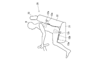
- FIG. 2 is a diagram showing sensor positions of a pulse wave sensor and a pressure sensor.
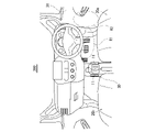
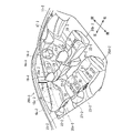
- FIG. 3 is a perspective view showing an example of arrangement of lighting units in a vehicle compartment.
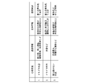
- FIG. 4 is a diagram for explaining the relationship between the driver's psychological state, road information, biological information, and lighting control.
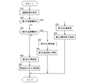
- FIG. 5 is a flowchart showing an example of the first control example.
- FIG. 6 is a flowchart showing an example of the second control example.
- FIG. 7 is a block diagram illustrating a modification of the first embodiment.
- FIG. 8 is a block diagram showing an example of the vehicle interior lighting device of the second embodiment.
- FIG. 1 is a block diagram showing an example of a vehicle interior lighting device according to a first embodiment.
- FIG. 2 is a diagram showing sensor positions of a pulse wave sensor and a pressure sensor.
- FIG. 3 is a perspective view showing an example of arrangement
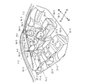
- FIG. 9 is a perspective view schematically showing the schematic configuration of the interior of the vehicle.
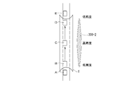
- FIG. 10 is a diagram explaining a third control example in the second embodiment.
- FIG. 11 is a perspective view schematically showing the schematic configuration of the passenger compartment in the third embodiment.
- FIG. 12 is a diagram showing a first lighting mode of the lighting section provided on the door trim.
- FIG. 13 is a diagram showing a second lighting mode of the lighting section provided on the door trim.
- FIG. 14 is a diagram showing a first lighting mode of the lighting section provided on the pillar.
- FIG. 15 is a block diagram showing a schematic configuration of a vehicle interior lighting system according to the third embodiment.
- FIG. 16 is a flow chart showing an example of lighting control in the third embodiment.
- FIG. 16 is a flow chart showing an example of lighting control in the third embodiment.
- FIG. 17 is a block diagram showing a schematic configuration of a vehicle interior lighting system when using a body temperature sensor in the fourth embodiment.
- FIG. 18 is a block diagram showing a schematic configuration of a vehicle interior lighting system when an odor sensor is used in the fourth embodiment.
- FIG. 19 is a block diagram showing the control system of the air conditioner in the fifth embodiment.
- FIG. 20 is a perspective view schematically showing the schematic configuration of the interior of the vehicle.
- FIG. 21 is a diagram showing a first light emission form of the lighting section provided on the door trim.
- FIG. 22 is a diagram showing a second light emission form of the lighting section provided on the door trim.
- FIG. 23 is a diagram showing a second light emission mode of the lighting section provided near the foot of the seat.
- FIG. 24A and 24B are diagrams showing a first light emission form of the illumination section provided on the pillar.
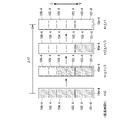
- FIG. FIG. 25 is a diagram showing how the remaining time is displayed by the illumination unit.
- FIG. 26 is a block diagram for explaining the sixth embodiment.
- FIG. 27 is a block diagram of a lighting device of modification 2 in the sixth embodiment.
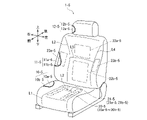
- FIG. 28 is a perspective view showing the appearance of the vehicle seat according to the seventh embodiment.
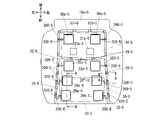
- FIG. 29 is a plan view of the seat cushion with the skin material removed.
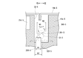
- 30 is a cross-sectional view taken along the line AA of FIG. 29.
- FIG. 31 is a diagram showing the relationship between the through hole, the tube, the suspending portion, and the locking portion.
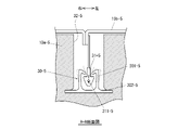
- 32 is a cross-sectional view taken along the line BB of FIG. 29.
- FIG. 33 is a diagram showing the seat cushion during operation of the cushion airbag.
- 34 is an enlarged view of the air cell arrangement portion of FIG. 29.
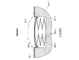
- FIG. FIG. 35 is a view showing a CC section when not inflated.
- FIG. 36 is a diagram showing a CC cross section at the time of expansion.
- FIG. 37 is a diagram explaining the seat back.
- FIG. 38 is a diagram for explaining the seat back when the air cells are inflated.
- FIG. 39 is a block diagram showing the air cell control system.
- FIG. 40 is a diagram showing another example of the arrangement of hanging locking members.
- FIG. 1 is a block diagram showing an example of a vehicle interior lighting device according to a first embodiment.
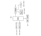
- a vehicle interior lighting device 1 shown in FIG. 1 includes a control device 10, a lighting unit 11 provided in the vehicle interior, a pulse wave sensor 12 and a pressure sensor 13 provided on a seat on which a driver sits.
- the pulse wave sensor 12 and the pressure sensor 13 detect the biological information of the driver sitting on the seat.
- the pulse wave sensor 12 detects the driver's pulse wave
- the pressure sensor 13 detects the seating posture of the driver. to detect changes in Road information is input from the navigation device 2 to the vehicle interior illumination device 1 .
- the control device 10 controls lighting by the lighting unit 11 based on the information about the driver detected by the pulse wave sensor 12 and the pressure sensor 13 and the road information input from the navigation device 2 .
- the control device 10 includes a lighting control unit 100 that controls the lighting unit 11, an estimation unit 101 that estimates the psychological state of the driver, a storage unit 102 that stores programs and data related to lighting control, and road information from the navigation device 2. is provided with a communication unit 103 for receiving the Estimation unit 101 estimates the driver's state of mind based on the detection results of pulse wave sensor 12 and pressure sensor 13 .
- the control device 10 includes a CPU (Central Processing Unit), a ROM that stores control programs, a memory such as a RAM that temporarily stores data, and peripheral devices (communication modules, etc.).
- the memory functions as a storage unit 102, and the CPU functions as a lighting control unit 100 and an estimation unit 101 according to control programs stored in the memory.
- the navigation device 2 may be a navigation device mounted on a vehicle, or may be a mobile terminal in which a navigation application is installed. In that case, the communication unit 103 of the control device 10 communicates with the mobile terminal by wireless communication.
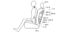
- FIG. 2 is a diagram showing the arrangement of the pulse wave sensor 12 and the pressure sensor 13 provided on the seat 20.
- the seat 20 includes a seat cushion 21 that supports the buttocks of the occupant D, a seat back 22 that supports the waist and back of the occupant, and a headrest 23 that is provided on the seat back 22 and supports the head of the occupant.
- the pulse wave sensor 12 (12a, 12b) detects a pulse wave as biological information from blood flow at a position facing the skin surface of the seated person.
- Pulse wave sensors 12 ( 12 a , 12 b ) are provided on seat cushion 21 and seat back 22 .
- the position of the pulse wave sensor 12a corresponds to the position of the seated person's heart (thoracic aorta), and is provided behind the skin of the seat back 22.
- the position of the pulse wave sensor 12a corresponds to the position of the seated person's buttocks (central part of the left and right ischial bones) or thighs, and is provided on the back side of the skin of the seat cushion 21 .
- two pulse wave sensors 12a and 12b are provided in the example shown in FIG. 2, the configuration may be such that only one of them is used.
- the pressure sensors 13 (13a to 13c) for detecting changes in the seating posture of the seated driver D are provided on the back side of the seat cushion 21 and the seat back 22 .
- the pressure values detected by the pressure sensors 13a to 13c are changed.
- the pulse wave sensor 12 for detecting the pulse wave for example, a photoelectric pulse wave sensor that measures the pulse wave of the seated person using light, or a pressure wave on the body surface of the seated person Examples include a piezoelectric pulse wave sensor that measures pulse waves, and an electromagnetic pulse wave sensor that measures the pulse waves of a seated person using electromagnetic waves. In the present embodiment, any one of these multiple types of pulse wave sensors may be employed, and these multiple types of pulse wave sensors may be used in combination as appropriate.
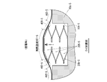
- FIG. 3 is a perspective view showing a schematic arrangement example of the lighting unit 11 inside the vehicle compartment 200.
- the illumination unit 11 is provided for the driver, and is provided on the side surface of the center console 30 in the example shown in FIG. As will be described later, the illumination unit 11 is provided to relieve the driver's psychological state such as tension and irritation with illumination light, and has a bluish illumination color.
- the arrangement of the illumination unit 11 is not limited to the arrangement shown in FIG. 3, and an arrangement that allows indirect light to reach the driver is preferable.
- an illumination unit 11 is provided under the seat 20, and the illumination unit 11 illuminates the vicinity of the driver's feet (area indicated by symbol R1), the door trim of the door 31 on the driver's side (area indicated by symbol R2), and the like.
- the vehicle interior lighting device 1 of the present embodiment detects the road information acquired from the navigation device 2 and/or the driver's psychological state based on the detection results of the pulse wave sensor 12 and the pressure sensor 13 that detect biological information. (such as the state of nervousness and irritability) is estimated, and the illumination unit 11 provides effective lighting to alleviate the driver's psychological state.
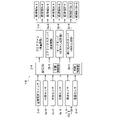
- FIG. 4 is a diagram showing an outline of the relationship between the driver's psychological state, road information, and driver's biological information, and the relationship between lighting control that alleviates the driver's psychological state, according to the present embodiment.
- the psychological state of the driver consider a first psychological state in which the driver is nervous, a second psychological state in which the driver is irritated, and a third psychological state in which the driver is restless.
- the first road information that evokes the first psychological state includes urban roads, narrow roads, roads with multiple lanes, and merging lanes.
- the second road information that evokes the second psychological state includes traffic congestion.
- the third road information that evokes the third psychological state includes roads with heavy traffic, roads that are rarely used, and roads in areas visited for the first time.
- the first biological information in the first psychological state is a state in which the pulse wave heart rate detected by the pulse wave sensor 12 is equal to or greater than a predetermined heartbeat threshold.
- the second biological information in the second psychological state there is a state in which the pulse wave fluctuates more than a predetermined pulse wave threshold.
- the third biological information in the case of being in the third psychological state there is a state in which the frequency of body movements is equal to or higher than a predetermined body movement threshold.
- the first to third psychological states are all unstable psychological states, and bluish lighting colors are known as lighting that softens such a driver's mental state.
- the first blue-based color and the second blue-based color change the color depth and/or intensity between the first psychological state and the second psychological state. do.
- a bluish light with a fluctuating light intensity that changes in a cycle corresponding to the cycle of the pulse wave is used.
- the power (spectral density) is a fluctuation inversely proportional to the frequency f
- the fluctuation of illumination resonates with the rhythm of the living body, the autonomic nerves are adjusted, and the mind is stabilized.
- the psychological state, the road information corresponding to the psychological state, and the biometric information are classified into three types, but the classification is not limited to these three types. Also, the types of road information and the types of biometric information are not limited to those shown in FIG.
- FIG. 5 is a flowchart showing an example of a first control example by the control device 10 .
- the driver's state of mind is estimated based on the road information acquired from the navigation device 2, and the lighting is controlled to soften the driver's state of mind based on the result of the estimation.
- the vehicle power is turned on, a series of processes shown in FIG. 5 are repeatedly executed at predetermined time intervals.
- step S10 road information is acquired from the navigation device 2.
- step S20 the estimation unit 101 determines whether the acquired road information corresponds to the first road information described above. If it is determined that the road information is the first road information in step S20, the driver is determined to be in the first state of mind in step S22, and the lighting unit 11 is turned on in a first blue-based color in step S24. On the other hand, if it is determined in step S20 that the road information is not the first road information, the process proceeds to step S30.
- step S30 it is determined whether or not the road information acquired in step S10 is the second road information. If it is determined that the road information is the second road information in step S30, the process proceeds to step S32, and if it is determined that the road information is not the second road information, the process proceeds to step S40. If it is determined that the road information is the second road information in step S30, the process advances to step S32 to determine that the driver is in the second state of mind. light up.
- step S30 determines that the road information is not the second road information in step S30.
- the process advances to step S40 to determine that the driver is in the third state of mind. Fluctuation illumination that changes periodically is performed. In this way, by changing the illumination by the illumination unit 11 in accordance with the road conditions on which the vehicle is traveling, the driver's psychological state affected by the road conditions can be alleviated, and safe driving can be improved. .
- FIG. 6 is a flowchart showing an example of the second control example. When the vehicle power is turned on, the series of processes shown in FIG. 6 are repeatedly executed at predetermined time intervals.
- step S110 of FIG. 6 road information is acquired from the navigation device 2.
- a step S120 acquires the pulse wave information detected by the pulse wave sensor 12 and the body motion information detected by the pressure sensor 13 as biological information of the driver.
- step S130 it is determined whether or not the road information acquired in step S110 corresponds to the first road information described above. If it is determined that the road information is the first road information in step S130, the process proceeds to step S142, it is determined that the driver is in the first state of mind, and in step S144 the lighting section 11 is turned on in the first blue-based color. .
- step S140 it is determined whether or not the biometric information acquired in step S120 corresponds to the first biometric information among the three types of classification shown in FIG. If it is determined in step S140 that it corresponds to the first biometric information, the processes of steps S142 and S144 described above are executed. On the other hand, if it is determined in step S140 that the first biological information does not apply, the process proceeds to step S150.
- step S150 it is determined whether or not the road information acquired in step S110 corresponds to the second road information described above. If it is determined that the road information is the second road information in step S150, the process proceeds to step S162 to determine that the driver is in the second state of mind, and in step S164 the lighting unit 11 is turned on in a second blue-based color. .
- step S150 determines whether or not the road information is not the second road information
- step S160 it is determined whether or not the biometric information acquired in step S120 corresponds to the second biometric information among the three types of classification shown in FIG. If it is determined in step S160 that it corresponds to the second biometric information, the processes of steps S162 and S164 described above are executed. On the other hand, if it is determined in step S160 that the third biological information does not apply, the process proceeds to step S170, and the driver is assumed to be in the third psychological state. Then, in step S180, the illumination unit 11 is controlled to fluctuate illumination of bluish colors.
- FIG. 7 is a diagram showing a modification of the first embodiment described above.
- the control device 10 includes an authentication unit 104 that authenticates who the driver is.
- the communication unit 103 can transmit and receive information to and from the mobile terminal 3 worn by the driver by wireless communication.
- the storage unit 102 stores the identification number of the mobile terminal 3 of each driver, the heartbeat threshold value, the pulse wave threshold value, and the body motion threshold value specific to each driver with respect to a plurality of drivers who drive the vehicle. .
- a search is made by wireless communication to see if the driver's mobile terminal 3 is detected.
- the driver's heartbeat threshold, pulse wave threshold, and body motion threshold corresponding to the identification number of the mobile terminal 3 are read, and these thresholds are used for the control described above.
- the storage unit 102 pre-stores pressure distribution data for each driver.
- the authentication unit 104 compares the pressure distribution detected by the pressure sensor 13 with a plurality of pressure distribution data stored in the storage unit 102 to identify the driver, and determines the heart rate threshold and pulse wave of the driver.
- the threshold and motion threshold are read and used for the control described above.
- the pulse wave sensor 12 and the pressure sensor 13 detect the driver's biological information (pulse wave, body motion).
- a digital camera may be provided, and photographed data of the digital camera may be used for detection of body movement and facial expression of the driver, and face authentication.
- FIG. 8 is a block diagram showing an example of the vehicle interior lighting device of the second embodiment.
- the control unit 10-2 has a communication unit 100-2 that receives navigation information from the navigation device 2-2.
- Control unit 10-2 controls lighting unit 14-2 (14b-2 to 14d- 2) and 15-2 (15b-2 to 15d-2).
- the control unit 10-2 includes a CPU (Central Processing Unit), a ROM storing control programs, a memory such as a RAM temporarily storing data, and peripheral devices (communication modules, etc.).
- the CPU functions as the control section 10-2 according to the control program stored in the memory.
- the navigation device 2-2 may be a navigation device mounted on a vehicle, or may be a mobile terminal in which a navigation application is installed. In that case, the communication unit 100-2 of the control unit 10-2 communicates with the mobile terminal by wireless communication. In the second embodiment, tunnel information obtained from the navigation device 2-2 is used for lighting control.
- FIG. 9 is a perspective view schematically showing the schematic configuration inside the vehicle compartment 200-2.
- the illuminance sensor 11-2 for detecting the illuminance outside the vehicle is generally installed outside the vehicle, but as shown in FIG. You can place it.
- Illumination units 14b-2 to 14d-2 and illumination units 15b-2 to 15d-2 are provided corresponding to the sheets 20b-2, 20c-2, and 20d-2.
- the seat 20a-2 on which the driver sits is not provided with the lighting units 14-2 and 15-2 in order to give priority to the driving environment.
- the lighting units 14b-2 to 14d-2 and the lighting units 15b-2 to 15d-2 are connected to the doors 4b-2, 4c-2, 4c-2, 4b-2, 4c-2, 4b-2, 4c-2, 4b-2, 4c-2, 4b-2, 4c-2, 4b-2, 4c-2, 4b-2, 4c-2, 4b-2, 4c-2, 4c-2, 4b-2, 4c-2, 4b-2, 4c-2, 4c-2, 4c-2, 4c-2, 4b-2, 4c-2, 4c-2, 4c-2, 4b-2, 4c-2, 4c-2, 4b-2, 4c-2, 20d-2, respectively, respectively. It is provided in the door trim of 4d-2 and the roof portion above the door.
- the illumination units 14b-2 to 14d-2 are illumination units that illuminate the hand areas of the passengers seated on the seats 20b-2 to 20d-2, respectively.
- the illumination units 14b-2 to 14d-2 are provided in the door trim, but the illumination units 14b-2 to 14d-2 are not limited to this as long as they can illuminate the hands. 22-2, instrument panel 17-2, or the like.
- the lighting units 15b-2 to 15d-2 can illuminate the entire passengers seated on the seats 20b-2 to 20d-2.
- the lighting units 15b-2 to 15d-2 are provided on the roof portion above the door, but they may be arranged on the pillars 16-2, 19-2 or the like.
- the doors 4b-2 and 4d-2 corresponding to the seats 20b-2 and 20d-2 and the lighting units 14b-2, 14d-2, 15b-2 and 15d-2 are omitted.
- Each of the seats 20a-2 to 20d-2 includes a seat cushion 21-2 that supports the buttocks of the occupant, a seat back 22-2 that supports the waist and back of the occupant, and a headrest 23-2 that supports the head of the occupant. and
- Each of the seats 20b-2 to 20d-2 has four pressure sensors S1 on the seat cushion 21-2 and one pressure sensor S2 on the seat back 22-2.
- a sleep detection unit 12-2 is configured by the pressure sensor S2 provided in the seat back 22-2
- a posture detection unit 13- is configured by the four pressure sensors S1 of the seat cushion 21-2 and the pressure sensor S2 of the seat back 22-2. 2 is configured.
- the detected value of the pressure sensor S2 provided in the seat back 22-2 periodically fluctuates according to the breathing period of the seated occupant.
- the control unit 10-2 determines that the user is in a sleeping state when the fluctuation period of the detection value of the pressure sensor S1 becomes longer than the threshold value for determining the sleeping state. Further, when the seated occupant changes his or her posture, the detected values of the pressure sensors S1 and S2 change before and after the posture change. The control unit 10-2 determines the seated posture of the occupant based on the values detected by the pressure sensors S1 and S2.
- the detected value of the front pressure sensor S1 becomes large, and the detected value of the rear pressure sensor S1 and the pressure sensor S2 of the seat back 22-2 increases. If it becomes smaller, it is determined that the center of gravity of the occupant has moved forward due to reading, playing games, or the like, and that the occupant is paying close attention to the vicinity of the hand. In other words, it is determined that the operator is in the sitting posture during manual work.
- pressure sensors arranged on the seat are used as the sleep detection unit 12-2 and the posture detection unit 13-2, but the configuration is not limited to this.
- a digital camera may be placed in the seat back 22-2, the instrument panel 17-2, or the like, and the sleeping state and posture of the occupant may be determined from the expression and posture of the occupant photographed by the digital camera.
- the control unit 10-2 causes the sleep detection unit 12-2 (specifically, the pressure sensor S2 provided on the seat 20c-2) corresponding to the seat 20c-2 to detect the sleep state. When detected, the lighting units 14c-2 and 15c-2 are turned off.
- the illumination unit 14c-2 when the illuminance detected by the illuminance sensor 11-2 is equal to or less than a predetermined value and the sleep detection unit 12-2 detects that the occupant is in a non-sleeping state (that is, an awake state), the illumination unit 14c-2, Light 15c-2.
- the predetermined value for example, an illuminance that interferes with reading can be considered.
- both of the lighting units 14c-2 and 15c-2 are provided, and both are turned on or off. Turns on or off one lighting unit that is in
- the illumination unit 14c for hand illumination -2 is lit.
- the lighting unit 14c-2 is further lit, while the lighting unit 14c-2 is lit. In that case, the lighting state is maintained.
- the lighting unit 14c-2 is turned on when the posture state during hand work is detected. Lights up. As a result, the lighting condition for the seat 20c-2 is suitable for reading.
- Third Control Example A third control example is a control example when tunnel information is input to control section 10-2 from navigation device 2-2 via communication section 100-2. For example, when a tunnel T as shown in FIG. 10 is obtained as navigation information, the illuminance of the illuminated lighting units 14c-2 and 15c-2 is controlled as indicated by hatching 300-2. The position of the running vehicle moves from the own vehicle position A to B, C, D, and E in this order.
- the illumination unit corresponding to the seat 20c-2 is turned on, and the center of the tunnel T is approached from the exit and entrance of the tunnel T.
- the illuminance of the lighting unit is increased as the value increases.
- FIG. 9 when two illumination units 14c-2 and 15c-2 are provided for the seat 20c-2, at least one of the illumination units 14c-2 and 15c-2 is turned on. .
- the illuminance is increased, and after passing the tunnel center, the illuminance is decreased as the vehicle approaches the tunnel exit.
- the center of the tunnel (vehicle position C) has the highest illuminance, the closer to the tunnel entrance and exit, the lower the illuminance, and the entrance (vehicle position B) and the exit (vehicle position D) have the highest illuminance. low.
- lighting according to the situation of each passenger can be performed by controlling the lighting of the lighting unit according to whether the passenger is in a sleeping state. For example, if the occupant is in a sleeping state, the illumination unit is turned off so that the illuminating light does not interfere with a good night's sleep. In addition, when the passenger is reading, the posture of the passenger is detected and the hand lighting units (14b-2 to 14d-2) are turned on, so that an optimum reading environment can be provided.
- FIG. 11 is a perspective view schematically showing the schematic configuration inside the passenger compartment 1-3 in the passenger compartment lighting system of the third embodiment.
- a total of four seats 2a-3 to 2d-3 are provided in the passenger compartment 1-3, including front seats 2a-3 and 2b-3 and rear seats 2c-3 and 2d-3. ing.
- Each of the seats 2a-3 to 2d-3 includes a seat cushion 20-3 that supports the buttocks of the occupant, a seat back 21-3 that supports the waist and back of the occupant, and a headrest 22-3 that supports the head of the occupant. and
- a seat heater 30-3 is provided on the seat cushion 20-3.
- the operation portion 31-3 of the seat heater 30-3 of each of the seats 2a-3 to 2d-3 is the door trim of the doors 4a-3 to 4d-3 provided corresponding to the respective seats 2a-3 to 2d-3. is provided in
- a lighting section 5a-3 is provided on the door trim of the door 4a-3 provided corresponding to the seat 2a-3.
- a door trim of a door 4c-3 provided corresponding to the seat 2c-3 is provided with an illumination section 5c-3.
- the door trims of the doors 4b-3 and 4d-3 provided corresponding to the seats 2b-3 and 2d-3 also have lighting units 5a-3 and 5c-3. Illumination units 5b-3 and 5c-3 similar to those are provided.
- the lighting units 5a-3 to 5d-3 are provided on the door trims of the doors 4a-3 to 4d-3. It is preferably located in a position where it can be seen by an occupant.
- the lighting section 5c-3 corresponding to the seat 2c-3 it may be provided on the pillar 6-3, the door trim lower region near the feet, the rear surface of the seat 2a-3, or the like.
- Air conditioning air outlets 8a-3 and 8b-3 are provided on both sides of the instrument panel 7-3, and a defroster outlet 8e-3 is provided in the center. is provided.
- An illumination unit 10a-3 is provided on the trim of the pillar 9-3 provided near the outlet 8a-3 on the left side.
- the pillar trim provided near the outlet 8b-3 (not shown) provided on the right side of the instrument panel 7-3 also has an illumination unit 10b-3. (not shown) are provided.
- the left and right pillars 6-3 are also provided with outlets 8c-3 and 8d-3 for blowing the conditioned air toward the seats 2c-3 and 2d-3.
- outlets 8c-3 and 8d-3 for blowing the conditioned air toward the seats 2c-3 and 2d-3.
- the illumination units 5a-3 to 5d-3, 10a-3, and 10b-3 are equipped with, for example, an LED that emits red light, an LED that emits green light, and an LED that emits blue light, and various lighting colors are possible. is configured to
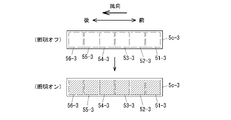
- FIGS. 12 and 13 are diagrams showing illumination modes of the illumination units 5a-3 to 5d-3, FIG. 12 showing the first illumination mode, and FIG. 13 showing the second illumination mode.
- FIGS. 12 and 13 show the illumination unit 5c-3 as an example, the illumination units 5a-3, 5b-3, and 5d-3 have the same configuration.
- the upper side of the drawing shows the lighting mode when the lighting is off, and the lower side of the drawing shows the lighting mode when the lighting is on (that is, the first lighting mode).
- the illumination section 5c-3 has a plurality of light emitting sections 51-3 to 56-3. Each of the light emitting units 51-3 to 56-3 has a red LED, a green LED and a blue LED, and can illuminate with various colors.
- All of the light emitting units 51-3 to 56-3 are extinguished when the illumination is off, and all of the light emitting units 51-3 to 56-3 are illuminated when the illumination is on.
- the light emitting portions 51-3 to 56-3 emitting light are hatched. That is, hatching indicates that light is emitted, and the same applies to the case of the second illumination mode shown in FIG.
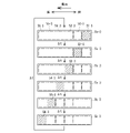
- FIG. 13 shows an illumination mode when the illumination is turned on, and six light emission patterns are repeated at predetermined time intervals ⁇ t.
- a first emission pattern a second emission pattern
- a third emission pattern a fourth emission pattern
- a fifth emission pattern a sixth emission pattern.
- the light emission pattern 1 only the light emitting portion 54-3 emits light, in the fifth light emitting pattern only the light emitting portion 55-3 emits light, and in the sixth light emitting pattern only the light emitting portion 56-3 emits light.
- the cooling setting/heating setting can be visualized by setting the illumination light to a cool color (e.g., blue) during cooling and to a warm color (e.g., red) during heating.
- Warm colors include red, orange, and yellow
- cold colors include dark blue, blue, and light blue.
- FIG. 14 is a diagram showing the lighting mode of the lighting section 10a-3.
- the illumination form of the illumination unit 10b-3 (not shown) is also the same as the form shown in FIG.
- the illumination section 10a-3 also has a first illumination mode as shown in FIG. 12 and a second illumination mode as shown in FIG.
- the lighting section 10b-3 has a plurality of light emitting sections 101-3 to 106-3 arranged in the extending direction of the pillar 9-3, that is, in the direction of the up and down arrows.
- the temperature-controlled air blown out from the outlet 8e-3 is blown upward substantially along the pillar 9-3.
- FIG. 14 shows a first illumination mode similar to that in FIG. , all the light emitting units 101-3 to 106-3 are turned on. Although illustration of the second illumination mode is omitted, only the light emitting unit 101-3 emits light in the first light emission pattern, only the light emitting unit 102-3 emits light in the second light emission pattern, and only the light emitting unit 102-3 emits light in the third light emission pattern. Only the light emitting unit 103-3 emits light, only the light emitting unit 104-3 emits light in the fourth light emitting pattern, only the light emitting unit 105-3 emits light in the fifth light emitting pattern, and the light emitting unit 105-3 emits light in the sixth light emitting pattern. Only 106-3 emits light. As in the case of FIG.
- the light emission region of the illumination section 10a-3 is changed from the bottom to the top (that is, the flow of the temperature controlled air direction) to create a visual effect that appears to flow.
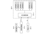
- FIG. 15 is a block diagram showing a schematic configuration of vehicle interior lighting system 200-3.
- the vehicle interior lighting system 200-3 controls illumination by the illumination units 5a-3 to 5d-3, 10a-3 and 10b-3 and the illumination units 5a-3 to 5d-3, 10a-3 and 10b-3.
- a lighting control device 201-3 includes a CPU (Central Processing Unit) that performs various kinds of arithmetic processing, a ROM that stores control programs, and a memory such as a RAM that temporarily stores data such as the detection signal.
- a CPU Central Processing Unit
- the lighting control device 201-3 receives air-conditioning information such as the air-conditioning set temperature T1, the room temperature Tr measured by the room temperature sensor 230-3, and the air volume from the air-conditioning control device 210-3. In addition, the lighting control device 201-3 receives temperature control set temperatures T2a to T2d from the seat temperature control device 220-3.
- the seat temperature control device 220-3 includes an operation unit 31-3 shown in FIG. The temperature of the seat heater 30-3 is controlled by controlling the current supplied to the seat heater 30-3.
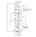
- FIG. 16 is a flowchart showing an example of lighting control in the third embodiment. As shown in FIG. 11, the vehicle is provided with five seats 2a-3 to 2d-3. 3, the lighting control shown in FIG. 16 is executed independently. Here, the illumination section 5c-3 provided corresponding to the seat 2c-3 will be described as an example. This lighting control is executed by the lighting control device 201-3, and the lighting control process starts when the power of the vehicle is turned on.
- step S210 in FIG. 16 it is determined whether or not the air conditioning control by the air conditioning control device 210-3 is on. If it is determined to be on (yes) in step S210, the process proceeds to step S220 to set the air conditioning flag F to ON. On the other hand, if it is determined to be off (no) in step S210, the process advances to step S212 to set the air conditioning flag F to OFF. In step S230, it is determined whether or not the seat temperature control for the seat 2c-3 is ON, that is, whether or not the occupant seated in the seat 2c-3 operates the operation unit 31-3 to turn the seat temperature control ON. be done.
- step S230 If it is determined in step S230 that the seat temperature control is turned off, the process advances to step S270 to turn off the illumination by the illumination section 5c-3, and the process proceeds to step S280. That is, when the seat temperature control is off regardless of whether the air conditioning control is on or off, the illumination by the illumination unit 5c-3 is turned off.
- a warm color for example, red
- step S250 it is determined in step S250 whether
- on the left side is the magnitude of the difference between the air conditioning set temperature T1 and the temperature control set temperature T2c, and ⁇ Tth on the right side determines whether or not the difference in set temperatures is such that the occupants cannot perceive it. is the threshold. That is, if
- step S250 the process proceeds to step S260 to determine whether or not the air conditioning set temperature T1 is higher than the temperature control set temperature T2c. If it is determined in step S260 that the air conditioning set temperature T1 is higher than the temperature control set temperature T2c (T1>T2c), the process proceeds to step S270 to turn off the lighting unit 5c-3. Conversely, if T1>T2c is not determined in step S260, that is, if it is determined that T1 ⁇ T2c, the process proceeds to step S272 where a warm color (for example, red) and the first color in FIG. Illumination mode (illumination ON) is used to control the illumination by the illumination unit 5c-3.
- a warm color for example, red
- FIG. Illumination mode illumination ON
- step S280 it is determined whether or not the vehicle power supply is turned off. If it is determined that it is on, the process returns to step S210, and if it is determined that it is off, the series of lighting control ends.
- the lighting control device 201-3 states that "the occupant seated on the seat 2c-3 does not feel cold, and the occupant There is no need to commit to the temperature feeling of the person', and the lighting unit 5c-3 is turned off.
- a plurality of lighting units 5a-3 to 5d- provided corresponding to each of the plurality of seats 2a-3 to 2d-3 in the vehicle interior 3, and based on the temperature difference between the air conditioning set temperature and the temperature control set temperature of the seat, which is the temperature sensing information of the occupants seated in each of the plurality of seats 2a-3 to 2d-3, each seat 2a-3. and a lighting control device 201-3 that individually controls the lighting colors of the lighting units 5a-3 to 5d-3 corresponding to 1 to 2d-3.
- the illumination by the illumination units 5a-3 to 5d-3 can be appropriately controlled according to the temperature sensed by each passenger.
- occupant discomfort caused by the air conditioning temperature setting can be alleviated by the visual effect of the lighting.
- Modifications 1 to 3 of the third embodiment will now be described.
- the lighting unit 5c-3 is controlled in the first lighting mode (lighting ON) shown in FIG.
- a second illumination form may be adopted.
- the second illumination mode is adopted only when the conditioned air is blown out from the outlet.
- warm color lighting is performed in the first lighting mode.
- the indoor temperature Tr measured by the indoor temperature sensor may be used instead of the air conditioning set temperature T1.
- the color tone of the illumination light may be changed according to the difference between the air conditioning set temperature T1 and the room temperature Tr.
- the color of illumination is changed to red, orange, and yellow, or the depth of color is changed, in order from a large temperature difference.
- the illumination color of the illumination units 5a-3 to 5d-3 is set to a cool color during cooling, and the illumination unit corresponding to the seat where the occupant who is judged to be feeling cold is seated. is a warm lighting color.
- the illumination color of the illumination unit 5a-3 is set to warm colors, and the other illumination units 5b-3 to 5d-3 are set to cold colors. Lighting color.
- Modification 3 relates to the lighting units 10a-3 and 10b-3 provided on the pillar 9-3.
- the occupants feel less cold due to the effect of the lighting colors of the lighting units 5a-3 to 5d-3.
- Modified Example 3 the fact that there is a passenger who feels cold among the passengers is notified using the lighting units 10a-3 and 10b-3. For example, if the illumination color of the illumination units 5a-3 to 5d-3 is set to a warm color in step S272 of FIG. 14 are turned on as shown in FIG. Alternatively, lighting on and lighting off may be alternately repeated.
- the lighting control as described above using the lighting units 10a-3 and 10b-3 it is possible to issue a notification prompting the user to change the air conditioning temperature setting.
- the state in which the conditioned air is blown out from the defroster outlet 8e-3 may be visualized using the lighting units 10a-3 and 10b-3. That is, when the defroster is activated, the illumination units 10a-3 and 10b-3 are controlled in the second illumination mode, and the illumination areas of the illumination units 10a-3 and 10b-3 flow from bottom to top. In that case as well, if the illumination color of the illumination units 5a-3 to 5d-3 is set to a warm color in step S272 of FIG. 3, change the lighting control of 10b-3.
- the color tone of the illumination light from the illumination units 10a-3 and 10b-3 is changed according to the temperature difference between the air conditioning set temperature and the room temperature, as in the case of the illumination units 5a-3 to 5d-3. You can do it. Also, the flow speed of the lighting area may be changed according to the air volume of the conditioned air.
- the biometric information includes body temperature, biogas, and facial expression of the occupant. Below, the case where body temperature is used and the case where biogas is used will be described.
- FIG. 17 is a block diagram showing a schematic configuration of vehicle interior lighting system 200-3 when body temperature is used.
- the schematic configuration inside the compartment 1-3 is the same as the configuration shown in FIG. 11 of the above-described third embodiment, so FIG. 11 will also be used for explanation.
- a body temperature sensor 240-3 for measuring the body temperature of the occupant is provided in the block diagram shown in FIG. 17, instead of the seat temperature control device 220-3 in the block diagram shown in FIG. 15, a body temperature sensor 240-3 for measuring the body temperature of the occupant is provided.
- the configuration other than body temperature sensor 240-3 is the same as the configuration in the block diagram of FIG.
- the body temperature sensor 240-3 is, for example, an infrared thermometer, and is provided in association with each of the sheets 2a-3 to 2d-3 in FIG.
- the body temperature sensor 240-3 is provided on the back side of the seat back 21-3 or the headrest 22-3 of the seats 2a-3 and 2b-3, and the seat 2c-3 on the rear side facing the body temperature sensor 240-3 is installed.
- the body temperature for example, the temperature of the face
- body temperature sensors 240-3 are arranged on the instrument panel 7-3 at positions where the seats 2a-3 and 2b-3 face each other to measure the body temperature of the occupants seated on the seats 2a-3 and 2b-3. is measured by each body temperature sensor 240-3.
- the body temperature Tc measured by each body temperature sensor 240-3 is input to the lighting control device 201-3.
- the lighting control device 201-3 changes the lighting colors of the lighting units 5a-3 to 5d-3 according to the temperature difference between the air conditioning set temperature T1 and the body temperature Tc. For example, when T1>Tc, it is determined that the occupant feels cold, and the illumination color is controlled to a warm color system. Conversely, if T1 ⁇ Tc, it is determined that the occupant feels hot, and the lighting color is controlled to a cool color. Further, when the air conditioning set temperature T1 and the body temperature Tc are approximately the same, it is determined that neither the cold nor the heat is felt, and the lighting units 5a-3 to 5d-3 are turned off.
- the temperature difference between the air conditioning set temperature T1 of the vehicle interior air conditioner and the body temperature Tc of the occupants seated on the seats 2a-3 to 2d-3 is used as occupant temperature information.
- the occupant's body temperature Tc as the temperature to be compared with the air conditioning set temperature T1
- the occupant's temperature sensing information can be determined more accurately.
- an odor sensor 250-3 is provided as shown in the block diagram of FIG. You can do it.
- An odor sensor 250-3 is provided on each of the seats 2a-3 to 2d-3, for example, on the headrest 22-3 and the seat back 21-3. Detect gases individually.
- thermal sweating is sweating that accompanies an increase in body temperature (for example, an increase in body temperature of about 0.25 to 0.5° C.) during hot weather or exercise, and is caused by eccrine sweat glands.
- Psychic perspiration is sweat caused by eccrine sweat glands and apocrine sweat glands in response to mental stimulation such as nervousness or surprise in public.
- the odor sensor 250-3 includes a sensor 250a-3 for detecting gas components released from secretions of apocrine sweat glands and a sensor 250b-3 for detecting gas components released from secretions from eccrine sweat glands. .
- a detection signal Sa is input to the illumination control device 201-3.
- detection signal Sb is input to illumination control device 201-3.
- the lighting control device 201-3 determines that it is mental sweating, and changes the lighting colors of the lighting units 5a-3 to 5d-3 so that the occupant's tension is relieved. Control the color tones that give a calm feeling.
- the lighting control device 201-3 determines that it is thermal perspiration, and controls the lighting color of the lighting units 5a-3 to 5d-3 to cool colors.
- the illumination colors of the illumination units 5a-3 to 5d-3 are controlled to cool colors, and the illumination units 10a-3 and 10b-3 are used in the same manner as in the third modification of the third embodiment. Therefore, lighting control may be performed to encourage lowering of the air-conditioning set temperature.
- the illumination color may be a cool color to lower the set temperature, or a warm color to indicate that the set temperature is too high.
- the odor sensor 250-3 detects the biological gases of the passengers sitting on the seats 2a-3 to 2d-3 as temperature-sensing information, and how the passengers perceive the temperature inside the vehicle is determined. Judgment was made from changes in the components of the biogas. Therefore, lighting control can be appropriately performed not only for the heat but also for the tension of the occupants.
- a digital camera is provided in place of the body temperature sensor 240-3 in FIG. Then, it is determined whether the occupant feels cold or hot from the expression of the occupant photographed by the digital camera.
- FIG. 19 is a diagram for explaining a fifth embodiment of the present invention, and is a block diagram showing a control system of an air conditioner.
- the air conditioner 1-4 shown in FIG. 19 shows the configuration in the case of an automatic air conditioner, and the overall control is performed by the air conditioner ECU 2-4.
- the air conditioning ECU (Electronic Control Unit) 2-4 includes a CPU (Central Processing Unit), a ROM that stores control programs, a memory such as a RAM that temporarily stores data, and peripheral devices (communication modules, etc.). ing.
- the CPU functions as an air conditioning controller 2A-4 and a lighting controller 2B-4 according to control programs stored in the memory.
- the air conditioner 1-4 includes a temperature setting switch 3-4 for setting a desired temperature, sensors 4a-4 to 4c-4, 5-4 and 6-4 for acquiring information on the interior and exterior of the vehicle, A blower fan 7-4 for adjusting air volume control, dampers 8a-4 to 8c-4 for adjusting temperature and controlling air outlets, and lighting units 9a-4 to 9f-4 provided in the passenger compartment. , 10a-4, 10b-4.
- the inside air sensor 4a-4 is a temperature sensor that detects the temperature inside the vehicle.
- the outside air sensor 4b-4 is a temperature sensor provided outside the passenger compartment and detects the temperature of the outside air.
- the sunshine sensor 4c-4 is a sensor that detects the amount of sunshine, and is arranged near the front shield of the instrument panel 17-4 inside the vehicle, for example.
- the droplet sensor 5-4 is a sensor that detects droplets scattered when the occupant coughs or sneezes.
- the seat sensor 6-4 is a sensor for detecting whether or not an occupant is seated on the seat, and is composed of, for example, a pressure sensor provided on the seat.
- the air mix damper 8a-4 is a damper that switches between inside and outside air, and is used for temperature control.
- the mode damper 8b-4 is a damper for switching the blowout port, and is composed of dampers provided at each conditioned air blowout port. By controlling the opening degree of each damper of the mode damper 8b-4, the on/off of the conditioned air blown out from the outlet and the air volume are adjusted.
- the intake damper 8c-4 is a damper that switches between inside and outside air.
- the air-conditioning control unit 2A-4 calculates the air-conditioning air temperature, blowing air volume, and air outlet based on the signals from each sensor so that the vehicle interior temperature reaches the set temperature, and operates the blower fan 7- based on the calculation results. 4 and dampers 8a-4 to 8c-4.
- the lighting control unit 2B-4 controls the lighting units 9a-4 to 9e-4, 10a-4, 10b- based on the air conditioning control information (air outlet, blowing air volume, droplet information, etc.) from the air conditioning control unit 2A-4. 4 lighting conditions (illumination color, light emission form, etc.) are controlled.
- FIG. 20 is a perspective view schematically showing the schematic configuration of the passenger compartment.
- a total of four seats 20a-4 to 20d-4 are provided in the passenger compartment 100-4, including front side seats 20a-4 and 20b-4 and rear side seats 20c-4 and 20d-4. ing.
- Each of the seats 20a-4 to 20d-4 includes a seat cushion 21-4 that supports the buttocks of the occupant, a seat back 22-4 that supports the waist and back of the occupant, and a headrest 23-4 that supports the head of the occupant.
- a seat sensor 6-4 is provided on the seat cushion 21-4.
- 5a-4 to 5d-4 are splash sensors, and each splash sensor 5a-4 to 5d-4 is arranged at a position facing the corresponding sheet 20a-4 to 20d-4.
- the splash sensor 5a-4 is arranged on the steering wheel
- the splash sensor 5b-4 is provided on the instrument panel 17-4
- the splash sensors 5c-4 and 5d-4 are on the back side of the seat back 22-4. are placed.
- a lighting section 9a-4 is provided on the door trim of the door 14a-4 provided corresponding to the seat 20a-4.
- a door trim of the door 14c-4 provided corresponding to the seat 20c-4 is provided with an illumination section 9c-4.
- the door trims of the doors 14b-4 and 14d-4 (not shown) provided corresponding to the seats 20b-4 and 20d-4 also have lighting units 9a-4. , 9c-4 are provided.
- a pair of lighting units 9e-4 (the lighting unit 9e-4 on the side of the seat 20a-4 is not shown) is provided at the feet of the seats 20a-4 and 20b-4. 4 are provided with a pair of lighting units 9f-4.
- the lighting units 9a-4 to 9d-4 are provided on the door trims of the doors 14a-4 to 14d-4. It is preferably located in a position where it can be seen by an occupant.
- the lighting section 9c-4 corresponding to the seat 20c-4 it may be provided in the pillar 16-4, the door trim upper to middle region, and the like.
- conditioned air outlets 18a-4 and 18b-4 corresponding to the seats 20a-4 and 20b-4 are provided.
- a defroster outlet 18i-4 is provided near the front shield in the center of the instrument panel 17-4.
- the pair of air outlets 18a-4 extracts the conditioned air toward the seat 20a-4 on which the driver sits, and the pair of air outlets 18b-4 extracts the air conditioned air toward the passenger side seat 20b-4.
- outlets 18c-4 and 18d-4 for blowing conditioned air are provided at the feet of the seats 20a-4 and 20b-4.
- a lighting section 10a-4 is provided on the trim of the pillar 19-4 provided near the outlet 18a-4 on the left side.
- the pillar trim provided near the outlet 18b-4 provided on the right side of the instrument panel 17-4 also has an illumination unit 10b-4 (not shown).
- the left and right pillars 16-4 are provided with outlets 18e-4 and 18f-4 for blowing conditioned air toward the seats 20c-4 and 20d-4.
- the illustration of the right pillar 16-4 and the outlet 18f-4 is omitted.
- Blow-out ports 18g-4 and 18h-4 are provided below the seats 20a-4 and 20b-4 to blow the conditioned air to the feet of the seats 20c-4 and 20d-4.
- the lighting units 9a-4 to 9f-4, 10a-4, and 10b-4 are equipped with, for example, an LED that emits red light, an LED that emits green light, and an LED that emits blue light, and various lighting colors are possible. is configured to
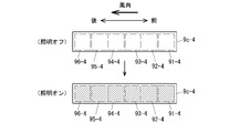
- FIGS. 21 and 22 are diagrams showing the light emission modes of the lighting units 9a-4 to 9d-4 provided on the door trim.
- FIG. 21 shows the first luminous form
- FIG. 22 shows the second luminous form.
- FIGS. 21 and 22 show the lighting section 9c-4 as an example, the lighting sections 9a-4, 9b-4, and 9d-4 have the same configuration.
- the upper side shows the light emission form when the illumination is off
- the lower side shows the light emission form when the illumination is on (that is, the first light emission form).
- the lighting section 9c-4 includes a plurality of light emitting sections 91-4 to 96-4.
- Each of the light emitting units 91-4 to 96-4 has a red LED, a green LED and a blue LED, and can illuminate in various colors. All the light emitting units 91-4 to 96-4 are extinguished when the illumination is off, and all the light emitting units 91-4 to 96-4 emit light in the first light emission mode.
- the light emitting portions 91-4 to 96-4 emitting light are hatched. That is, hatching indicates that light is emitted, and the same applies to the case of the second light emission mode shown in FIG.
- illumination is performed in such a form that the light emission area flows from the front to the rear of the vehicle compartment.
- six light emission patterns are repeated at predetermined time intervals ⁇ t.
- a first light emission pattern a second light emission pattern
- a third light emission pattern a fourth light emission pattern
- a fifth light emission pattern a sixth light emission pattern.
- the light emission pattern 2 only the light emitting portion 94-4 emits light, in the fifth light emitting pattern only the light emitting portion 95-4 emits light, and in the sixth light emitting pattern only the light emitting portion 96-4 emits light.
- the cooling setting/heating setting can be visualized by setting the illumination light to a cool color (e.g., blue) during cooling and to a warm color (e.g., red) during heating.
- Warm colors include red, orange, and yellow
- cold colors include dark blue, blue, and light blue.
- FIG. 23 is a diagram showing the light emission form of the illumination section 9e-4.
- the illumination unit 9e-4 is provided with a plurality of light emitting units 91-4 to 96-4 arranged downward from the upper side, and all the light emitting units 91-4 to 96-4 emit light as in the case of FIG.
- the light can be emitted in the first light emission form in which the light is emitted, and in the second light emission form in which the light emission area moves in a flowing manner as in the case of FIG. 22 .
- FIG. 23 shows a second luminous form in which the luminous region flows from top to bottom.
- the illumination section 9f-4 can also perform light emission control similar to that of the illumination section 9e-4.
- a first light emission pattern in which only the light emitting section 91-4 emits light a second light emission pattern in which only the light emitting section 92-4 emits light, and a third light emission pattern in which only the light emitting section 93-4 emits light.
- a fourth light emission pattern in which only the light emitting section 94-4 emits light a fifth light emission pattern in which only the light emitting section 95-4 emits light; and a sixth light emission pattern in which only the light emitting section 96-4 emits light. Iterate in order with ⁇ t.
- the wind direction of the outlets 18c-4 and 18d-4 for blowing the conditioned air downward can be represented by the movement of the illumination area.
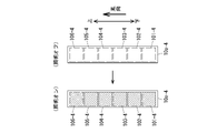
- FIG. 24 is a diagram showing the light emission form of the illumination section 10a-4.
- the light-emitting sections are arranged vertically in the same manner as in the lighting section 9e-4.
- the light emitting sections 101-4 to 106-4 are arranged in order from the bottom. As shown in FIG. 24, all the light emitting units 101-4 to 106-4 are turned off when the illumination is off, and all the light emitting units 101-4 to 106-4 are turned on when the illumination is on in the first light emission mode. .
- a first light emission pattern in which only the light emitting section 101-4 emits light a second light emission pattern in which only the light emitting section 102-4 emits light, and only the light emitting section 103-4 emits light.
- a fourth light emission pattern in which only the light emitting section 104-4 emits light a fifth light emission pattern in which only the light emitting section 105-4 emits light
- the pattern is repeated in sequence at time intervals ⁇ t.
- the air conditioner 1-4 shown in FIG. 19 performs two different types of air conditioning control according to the detection result of the droplet sensor 5-4.
- first air conditioning control a general automatic air conditioner
- second air conditioning control a second air conditioning control different from the normal control
- the first air conditioning control is the normal control in a general automatic air conditioner as described above, and the temperature set by the temperature setting switch 3-4, the inside air sensor 4a-4, the outside air sensor 4b-4, and the sunshine sensor 4c-4 Based on each detection information, the blowing temperature of the conditioned air and the opening/closing state of the blowing port are calculated so that the temperature in the passenger compartment becomes the set temperature, and based on the calculation result, the blower fan 7-4 and each damper 8a- 4 to 8c-4 are controlled. Description of the details of the control is omitted.
- Second air conditioning control Droplet detection control
- the air conditioning control section 2A-4 executes the second air conditioning control. If the passenger has a cold, there is a possibility that the droplets of the passenger's cough or sneeze may contain viruses or the like that cause the cold. In that case, in order to prevent transmission to other occupants, it is preferable to prevent droplets emitted from an occupant suffering from the cold from traveling to other occupants.
- air-conditioning control is performed to ventilate the air in the passenger compartment and to suppress the movement of droplets to other occupants.
- the basic operation is to suppress the flow of air-conditioned air from the seat corresponding to the droplet sensor 5-4 from which droplets are detected to other seats.
- the air circulation mode (a) is set so that droplets do not move to the rear seat.
- the air in the vehicle is discharged to the outside of the vehicle through the grill provided at the rear of the vehicle. mode.
- the intake damper 8c-4 is controlled to the inside air circulation side. Furthermore, when an occupant with a cold is seated on the seat 20a-4, the conditioned air is blown out from the air outlet 18c-4 to the foot of the seat 20a-4, and the air outlet 18b is blown to the seat 20b-4. Air-conditioned air is blown out from seat 20c-4, 20d-4 on the rear side from air outlets 18e-4, 18f-4 or air outlets 18e-4 to 18h-4. The air volume of the outlet 18c-4 is made smaller than the air volumes of the other outlets.
- the conditioned air is blown out from the air outlet 18d-4 to the foot of the seat 20b-4, and the air outlet 18a is directed to the seat 20a-4.
- Air-conditioned air is blown out from seat 20c-4, 20d-4 on the rear side from air outlets 18e-4, 18f-4 or air outlets 18e-4 to 18h-4.
- the air volume of the outlet 18d-4 is made smaller than the air volumes of the other outlets.
- the intake damper 8c-4 is controlled to the outside air introduction side. Furthermore, the conditioned air is blown out from the outlets 18a-4, 18b-4 for the front seats 20a-4, 20b-4, and the outlets 18e- for the rear seats 20c-4, 20d-4. 4, 18f-4 or air outlets 18e-4 to 18h-4 blow out the conditioned air.
- the air volume of the outlets 18e-4 to 18h-4 is made smaller than the air volume of the other outlets 18a-4 to 18d-4.
- the inside air circulation mode and the outside air introduction mode described above may be continued until the seating sensor 6-4 of the seat corresponding to the droplet sensor 5 that detected the droplet detects that the seat is not seated and is turned off. It may be performed only for a time corresponding to the amount of droplets applied. Further, in the outside air introduction mode, the air volume of the outlets 18a-4 to 18d-4 may be changed according to the amount of droplets detected by the droplet sensor 5-4. The larger the amount of droplets, the larger the air volume.
- Lighting control in each air conditioning control described above will be described.
- the light emission form of the lighting units 9a-4 to 9d-4 is the second light emission shown in FIG. form.
- the flow of the conditioned air blowing out from the outlets 18a-4, 18b-4, 18e-4, and 18f-4 is visualized by the second light-emitting mode in which the light-emitting region flows from the front to the rear.
- the light emission form of the lighting units 9e-4, 9f-4 is the second light emission shown in FIG. form.
- the flow of the conditioned air blowing out from the outlets 18c-4, 18d-4, 18g-4 and 18h-4 is visualized by the second light emitting form in which the light emitting region flows from top to bottom.
- the flow direction and flow rate of the conditioned air blown out from the blowout port 18i-4 can be controlled. can be visualized.
- the time interval ⁇ t is set small to increase the flow speed of the illuminated region, and when the air volume is small, the time interval ⁇ t is set large to slow the flow speed of the illuminated region.
- the magnitude of the air volume can be visualized by the speed of the flow in the illuminated area. Cooling and heating may be expressed by changing the lighting colors of the lighting units 9a-4 to 9f-4, 10a-4, and 10b-4.
- the illumination light is set to a cool color (eg, blue) during cooling, and is set to a warm color (eg, red) during heating.
- a cool color eg, blue
- a warm color eg, red
- the level of the set temperature may be represented by the intensity of the illumination color.
- the pillar 19-4 is used as a sign to notify that there is a passenger with a cold.
- the provided illumination units 10a-4 and 10b-4 are illuminated in the first light emission mode.
- the illumination color is not particularly limited, it is assumed to be red, which represents danger, for example. This allows all passengers to recognize that there is a passenger who has a cold.
- the amount of droplets detected by the droplet sensor 5-4 may be represented by the color tone of the lighting units 10a-4 and 10b-4. For example, the lighting colors of the lighting units 10a-4 and 10b-4 are changed to yellow, orange, pale red, and dark red as the droplet amount increases.
- the flow and direction of the conditioned air blown out from each of the outlets 18a-4 to 18h-4 are determined by the lighting units 9a-4 and 9b-4 corresponding to the outlets 18a-4 and 18b-4, the outlets 18c-4, A pair of illumination units 9e-4 corresponding to 18d-4, illumination units 9c-4 and 9d-4 corresponding to outlets 18e-4 and 18f-4, and a pair of outlets 18g-4 and 18h-4 corresponding to It can be expressed by the luminous form and the movement speed of the luminous area of the illumination section 9f-4.
- Information as to which seat the occupant with the common cold is seated is notified by the lighting colors of the lighting units 9a-4 to 9b-4.
- the color of the lighting unit 9c-4 corresponding to the seat 20c-4 is dark red, and the other lighting units 9a-4, 9b- The color of 4,9d-4 is light red.
- the remaining time for the inside air circulation mode or the outside air introduction mode to be performed may be displayed using the illumination unit.
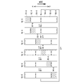
- illumination control as shown in FIG. 25 is performed by the illumination units 10a-4 and 10b-4.
- the predetermined time is ⁇ t1
- the elapsed time can be visualized by the decrease of the light-emitting portion. Therefore, the occupant can easily recognize how long the inside air circulation mode or the outside air introduction mode as described above will be performed, and the end time.
- the air conditioner 1-4 includes the plurality of conditioned air outlets 18a-4 to 18i-4 provided in the passenger compartment 100-4, and the plurality of conditioned air outlets 18a- A plurality of lighting units 9a-4 to 9f-4, 10a-4, and 10b-4 provided corresponding to 4 to 18i-4, and air-conditioned air blown out from air-conditioned air outlets 18a-4 to 18i-4. and lighting units 9a-4 to 9f-4, 10a-4, and 10b depending on the state of the air-conditioned air blown out from the air-conditioned air outlets 18a-4 to 18i-4. -4, and a lighting control unit 2B-4 for controlling the lighting mode of the lighting device 2B-4.
- the state of the air-conditioned air blown out from the outlet is visualized by the lighting forms of the lighting units 9a-4 to 9f-4, 10a-4, and 10b-4, and the occupants recognize the state of the air-conditioned air by the lighting forms of the lighting units. be able to.
- a droplet sensor 5-4 is further provided as a detection unit for detecting the biological information of the occupant, and the air conditioning control unit 2A-4 controls the state of the air-conditioned air based on the detection result of the droplet sensor 5-4, and controls the lighting.
- the unit 2B-4 may control the lighting mode based on the detection result of the droplet sensor 5-4 and the control of the air conditioning control unit 2A-4.
- Modification 1 of the fifth embodiment will be described.
- the control of modification 1 is suitable for applications such as taxis.
- ventilation control is performed only for a predetermined period of time when a passenger who has a cold gets out of the vehicle.
- the air conditioning control unit 2A-4 automatically performs ventilation control for a predetermined period of time when an occupant suffering from a cold gets off the vehicle and the state of the seat sensor 6-4 of the seat on which the occupant has been seated changes from on to off. do it purposefully.
- ventilation is carried out for a predetermined time ⁇ t2 by blowing out the conditioned air introduced from the outside air from the outlets 18a-4 to 18h-4. In that case, if lighting control as shown in FIG. 25 is employed, the effective state of ventilation and the end of ventilation can be visually recognized.
- control like the first modification of the fifth embodiment is performed, and indoor ventilation During execution, it is preferable that the air conditioning ECU 2-4 output a command to prohibit opening and closing of the vehicle door to the vehicle door opening and closing control section. As a result, it is possible to prevent the next user from getting on the vehicle with insufficient ventilation.
- FIG. 26 is a block diagram for explaining the sixth embodiment.
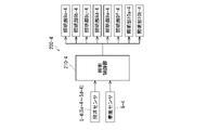
- a lighting device 200-4 is provided independently from the air conditioner 1-4, and based on information from the droplet sensors 5-4 (5a-4 to 5b-4) and the seating sensor 6-4, The air-conditioning command and the lighting control command for the second air-conditioning control described in the fifth embodiment are generated by lighting control unit 210-4 of lighting device 200-4.
- the air conditioning command is generated only when droplets are detected by the droplet sensor 5-4, and is transmitted from the communication unit 220-4 to the air conditioning ECU 2-4.
- Lighting control unit 210-4 of lighting device 200-4 receives air-conditioning information from air-conditioning ECU 2-4 via communication unit 220-4 regardless of whether droplets are detected or not.
- Air-conditioning ECU 2-4 executes normal control (first air-conditioning control) described in the fifth embodiment when no air-conditioning command is input from lighting control unit 210-4.
- the lighting control unit 210-4 performs lighting control of the lighting units 9a-4 to 9f-4, 10a-4, and 10b-4 based on the air conditioning information regarding the first air conditioning control input from the air conditioning ECU 2-4. .
- This lighting control is the same as the lighting control during the first air conditioning control in the fifth embodiment, so the description is omitted.
- the lighting control unit 210-4 causes the air conditioner 1-4 to perform the fifth operation based on the droplet detection result. It generates an air-conditioning command for performing the second air-conditioning control (droplet detection control) described in the embodiment, and transmits the air-conditioning command to the air-conditioning ECU 2-4.
- air-conditioning ECU 2-4 receives an air-conditioning command relating to the second air-conditioning control from lighting device 200-4, air-conditioning ECU 2-4 executes second air-conditioning control based on the air-conditioning command instead of normal control (first air-conditioning control).
- the air conditioning information at that time is transmitted from the air conditioning ECU 2-4 to the lighting device 200-4.
- the lighting control unit 210-4 When the lighting control unit 210-4 receives the air conditioning information from the air conditioning ECU 2-4, the lighting control unit 210-4 controls the lighting units 9a-4 to 9f-4, 10a-4 and 10b-4 based on the air conditioning information. This lighting control is the same as the lighting control during the second air conditioning control in the fifth embodiment, and the description thereof will be omitted.
- lighting control in lighting device 200-4 was performed based on the air conditioning information input from air conditioning device 1-4.
- the lighting control unit 210-4 generates an air-conditioning command (second air-conditioning control) and a lighting control command corresponding to the air-conditioning command, and based on the lighting control command, the lighting units 9a-4 to 9f- 4, 10a-4, and 10b-4 may be controlled.
- the same air conditioning control command and lighting control command as in the case of the modification 1 of the fifth embodiment are generated, and the modification 1 Air-conditioning control and lighting control similar to 1 may be performed.
- the lighting units 9a-4 to 9f- can notify that there is a passenger who has a cold, and notify that the air-conditioning state is set to the air-conditioning state in the second air-conditioning control as the air-conditioning state. 4, 10a-4, 10b-4.
- the illumination device 200-4 shown in FIG. 27 generates illumination control commands similar to those in the sixth embodiment described above, and controls illumination of the illumination units 9a-4 to 9f-4, 10a-4, and 10b-4. to control. For example, by controlling the illumination units 10a-4 and 10b-4 provided on the pillar 19-4 to the first light emission form (illumination ON) as shown in FIG. can be notified. Also, the occupant can recognize how the air conditioning state of the manual air conditioner should be changed by the lighting modes of the lighting units 9a-4 to 9f-4.
- the lighting device 200-4 is a vehicle interior lighting device for a vehicle equipped with the air conditioner 1-4, and is provided corresponding to the air conditioning air outlets 18a-4 to 18i-4 in the vehicle interior.
- a lighting control unit 210-4 that controls the lighting modes of the lighting units 9a-4 to 9f-4, 10a-4, and 10b-4 based on the air conditioning information input to the control unit 210-4. Based on the air-conditioning information from the air conditioner 1-4, the lighting modes of the lighting units 9a-4 to 9f-4, 10a-4, and 10b-4 are controlled, so that the air-conditioning state is visualized by the lighting. can be easily recognized.
- the droplet sensor 5-4 is provided as a detection unit for detecting the biological information of the occupant, but instead of the droplet sensor 5-4, a body temperature sensor (for example, an infrared thermometer) may be used.
- a body temperature sensor For example, an infrared thermometer
- the droplet sensor 5-4 and the temperature sensor may be used to detect the biological information (physical condition) of the occupant.
- FIG. 28 is a perspective view showing the appearance of a vehicle seat provided in a vehicle interior equipped with a vehicle interior lighting device.
- the seat 1-5 includes a seat cushion 10-5 that supports the buttocks of the occupant, a seat back 11-5 that supports the waist and back of the occupant, and a seat back 11-5 that supports the head of the occupant.
- a headrest 12-5 is provided.
- the coverings of the seat cushion 10-5, the seat back 11-5 and the headrest 12-5 are partially broken to expose the internal cushion material.
- the seat cushion 10-5 has a cushion frame (not shown) as a skeleton, and a cushion material 10a-5 made of urethane foam or the like is placed on the cushion material 10a-5. It is coated.
- the seat back 11-5 has a cushion material 11a-5 placed on a back frame (not shown) serving as a skeleton, and the cushion material 11a-5 is covered with a skin material 11b-5.
- the headrest 12-5 has a core material (not shown) provided with a cushion material 12a-5, and the cushion material 12a-5 is covered with a skin material 12b-5.
- the headrest 12-5 is supported by headrest pillars (not shown) provided on the back frame described above.
- a plurality of air cells 20-5 (20a-5 to 20h-5) and a plurality of pressure sensors 21- 5 (21a-5, 21b-5) are provided.
- Lumbar supports 22a-5 and 22b-5 which are a type of air cells, are provided on the back side of the cushion material 11a-5 of the seat back 11-5.
- Lumbar supports 22a-5 and 22b-5 are provided on a back frame (not shown).
- Pressure sensors 23a-5 and 23b-5 are provided on both left and right sides of the cushion material 11a-5 of the seat back 11-5.
- Suspension of the upholstery material using suspension locking members, which will be described later, is provided along the suspension lines L1 to L5 of the seat 1-5.
- FIG. 29 shows air cells 20-5 (20a-5 to 20h-5), pressure sensors 21-5 (21a-5, 21b-5), and suspensions provided in the cushion material 10a-5 of the seat cushion 10-5.
- FIG. 10 is a diagram showing the arrangement of locking members 30-5; A hanging portion, which will be described later, is provided on the back surface of the skin material 10b-5 covering the cushion member 10a-5. Lock at -5. As a result, the skin material 10b-5 covers the surface of the cushion material 10a-5 while being fixed in a predetermined shape.
- the hanging locking member 30-5 is provided inside a hanging groove 32-5 formed on the surface side of the cushion material 10a-5.
- the hanging groove 32-5 is formed at a position facing the hanging lines L1 and L2 in FIG. In the example shown in FIG. 29, a total of thirteen hanging locking members 30-5 are arranged in the hanging groove 32-5.
- the air cells 20a-5 to 20h-5 provided in the seat cushion 10-5 are arranged inside recesses 101-5 formed on the surface side of the cushion material 10a-5.
- the air cells 20a-5 to 20h-5 are used to finely adjust the hardness and holdability of the seat surface.
- Each of the air cells 20a-5 to 20h-5 is connected to a flexible tube 200-5 for supplying air for inflating the air cells 20a-5 to 20h-5.
- Each tube 200-5 passes through a through-hole 320-5 formed inside the hanging groove 32-5, is pulled out to the back side of the seat cushion 10-5, and is connected to a solenoid unit (not shown).
- Pressure sensors 21a-5 and 21b-5 are fixed by adhesion or the like to the surface of the back side (rear side of the seat) of the cushion material 10a-5. These pressure sensors 21a-5 and 21b-5 are used to determine whether or not the seated person is seated all the way into the seat cushion 10-5.
- a seat heater 40-5 is provided on the upper surface of the cushion material 10a-5, that is, between the cushion material 10a-5 and the upholstery material 10b-5.
- the seat heater 40-5 is made by arranging a heater portion composed of a heating wire or the like on a sheet-shaped nonwoven fabric as a base fabric, and is flexible.
- a cushion airbag 42-5 is provided on the rear side of the front region of the cushion material 10a-5.
- FIG. 30 is a cross-sectional view taken along the line AA of FIG. 29, showing a section of the hanging locking member 30-5 arranged in the hanging groove 32-5.
- Suspension locking member 30-5 includes suspension locking portion 301-5 for locking suspension portion 31-5 provided on the back side of skin material 10b-5, and suspension locking member 30-5 as a cushion. and a fixing portion 302-5 fixed to the member 10a-5. Both the hanging portion 31-5 and the locking portion 301-5 extend by a predetermined length in the groove extending direction with the cross-sectional shape shown in FIG.
- the locking portion 301-5 When the hanging portion 31-5 is pushed in the direction of the hanging locking member 30-5 as indicated by the dashed arrow, the locking portion 301-5 is elastically deformed as indicated by the thin line, and the arrowhead of the hanging portion 31-5 is formed.
- a shaped tip portion (hereinafter referred to as a locked portion 311-5) is inserted into the locking portion 301-5.
- the locked portion 311-5 of the hanging portion 31-5 is completely inserted into the locking portion 301-5, the elastically deformed locking portion 301-5 returns to its original shape and the hanging portion 31-5 returns to its original shape.
- the portion 31-5 is locked to the locking portion 301-5.
- FIG. 31 is a diagram showing the relationship between the through hole 320-5 and the tube 200-5 formed in the hanging groove 32-5, the hanging portion 31-5 and the locking portion 301-5.
- the hanging portion 31-5 and the locking portion 301-5 are indicated by two-dot chain lines.
- the through hole 320-5 penetrates from the hanging groove 32-5 formed on the surface side of the cushion material 10a-5 to the back surface side of the cushion material 10a-5.
- a tube 200-5 for supplying air to the air cell 20d-5 is inserted through the through hole 320-5 from the side of the hanging groove 32-5 to the rear side.
- the through hole 320-5 is provided biased toward the air cell 20d-5 with respect to the widthwise center of the hanging groove 32-5.
- the through hole 320-5 is provided biased toward the air cell 20d-5 side. Therefore, there is an advantage that the tube 200-5 can be easily inserted into the through hole 320-5. Further, when the upholstery material 10b-5 is put on the cushion material 10a-5 and the suspension part 31-5 is locked to the suspension locking member 30-5, the suspension part 31-5 is attached to the tube 200. It is possible to suppress interference with -5, and it is excellent in workability.
- the tube 200-5 is crawled across the hanging groove 32-5, so that the tube 200-5 can be hung during the locking operation. Portion 31-5 may interfere with tube 200-5.
- the diameter D1 of the tube 200-5 is set such that D1>W1 with respect to the groove width direction dimension W1 of the engaged portion 311-5 of the hanging portion 31-5.
- D1>W1 Even if the tube 200-5 is erroneously placed on the locking portion 301-5 as indicated by the two-dot chain line, the tube 200-5 is positioned above the locking portion 301. -5 can be prevented from being engaged.
- the diameter D2 of the through hole 320-5 is set such that W2>D2>D1.
- the hanging locking member 30-5 and the through hole 320-5 through which the tube 200-5 is inserted are provided apart from each other.
- the suspension portion 31-5 may be pressed against the tube 200-5 during the locking operation. , the tube 200-5 may be crushed or bent.
- the suspension locking member 30-5 and the through-hole 320-5 with a space therebetween, such a problem does not occur.
- a plurality of suspension locking members 30-5 and through holes 320-5 are arranged in the suspension groove 32-5.
- the stop members 30-5 are alternately arranged in the groove. If the suspension locking member 30-5 is not arranged in the range of the plurality of through holes 320-5, the suspension is not performed in that range, so the fixed shape of the upholstery 10b-5 deviates from the predetermined shape. There is a risk. However, by alternately arranging the through holes 320-5 and the hanging locking members 30-5 as shown in FIG. can be prevented from occurring.
- the seat cushion 10-5 When manufacturing the seat cushion 10-5, first, on the cushion material 10a-5 having the hanging groove 32-5 in which the hanging locking member 30-5 and the through hole 320-5 are spaced apart, air cells 20a-5 to 20h-5 that are inflated by air are arranged. Then, a tube 200-5 for supplying air to the air cells 20a-5 to 20h-5 is inserted through the through-hole 320-5 and routed on the back side of the cushion material 10a-5. Next, the cushion material 10a-5 is covered with the skin material 10b-5 provided with the suspension part 31-5 on the back side, and the suspension part 31-5 is attached to the suspension hook provided on the cushion material 10a-5. It is locked by the stop member 30-5.
- FIG. 32 is a diagram for explaining the cushion airbag 42-5, and is a cross-sectional view taken along the line BB in FIG.
- the cushion airbag 42-5 is provided in an airbag holding portion 43-5 provided below the cushion material 10a-5.
- the cushion airbag 42-5 is intended to prevent the submarine phenomenon in which the occupant passes through the seat belt and is thrown forward in the event of a traffic accident.
- FIG. 32 shows the state before the cushion airbag 42-5 operates, and the state shown in FIG. 33 occurs after the cushion airbag 42-5 operates.
- the cushion airbag 42-5 inflates momentarily in the event of a traffic accident. As a result, the front portion of the seat cushion 10-5 rises upward to prevent the occupant from being thrown forward.
- the cushion airbag 42-5 is designed so that the air is released immediately after being inflated momentarily.
- a hanging locking member 30-5 is provided. That is, at least the hanging locking member 30- is placed in the hanging groove 32-5 outside the region where the cushion airbag 42-5 in FIG. Place 5. Suspension locking members 30-5 arranged on the left and right sides of the dashed line area in FIG. 29 are outside the dashed line area, so deformation of the cushion member 10a-5 is relatively small. In order to further reduce the influence of the deformation of the cushioning material 10a-5, as shown in FIG. Preferably, an inset locking member 30-5 is provided.
- the tube 200-5 connected to the air cells 20e-5 to 20h-5 is routed around the through-hole 320-5 not at the shortest distance but with a margin. In that case, a part of the tube 200-5 may be arranged along the groove in the hanging groove 32-5.
- the diameter D1 of the tube 200-5 is set such that D1>W1 with respect to the groove width direction dimension W1 of the engaged portion 311-5, so the tube 200-5 is engaged. There is no such thing as being locked by the stop portion 301 .
- FIG. 34 is an enlarged view of the portion where the air cells 20a-5 and 20b-5 of FIG. 29 are arranged.
- 35 and 36 are CC sectional views of FIG. In FIGS. 34 and 35, illustration of the skin material 10b-5 is omitted.
- FIG. 35 shows a state in which the air cell 20b-5 is not inflated. When the air cell 20b-5 is inflated, the state shown in FIG. 36 is obtained.
- the heater wire 404-5 which is a heater member, is arranged so as to avoid the vertex P when the air cells 20a-5 and 20b-5 are expanded.
- Heater wires 404-5 are also provided in the same manner in the area where the air cells 20c-5 to 20h-5 of the seat heater 40-5 are provided.
- the air cell 20b-5 has a structure in which the bag-like bodies 205-5 are stacked vertically in three stages, but the number of stages is not limited to three, and may be one. .
- the three bag-shaped bodies 205-5 communicate with each other at their central portions. 35 and 36, the illustration of the tube 200-5 for supplying air to the air cell 20b-5 is omitted.
- the above-described seat heater 40-5 is provided on the upper surfaces of the cushion material 10a-5 and the air cell 20b-5.
- the seat heater 40-5 When the air cell is inflated as shown in FIG. 36, the seat heater 40-5 is pushed upward by the air cell 20b-5 and assumes an upwardly convex shape.
- the seat heater 40-5 At the time of non-expansion shown in FIG. 35, it becomes substantially flat as a whole.
- the seat heater 40-5 cannot freely expand and contract, the seat heater 40-5 has a margin as shown in FIG. A long portion 400-5 is provided.
- the seat heater 40-5 has a heating portion such as a heating wire provided on a sheet-like nonwoven fabric that is a base fabric.
- heating units are provided in heating regions 401-5 and 402-5.
- the surplus length portion 400-5 is not provided with a heating portion and is configured to be easily bent.
- the base fabric is given a crease so that it can be easily bent when not inflated.
- a flexible lead wire may be provided in the extra length portion 400-5 to electrically connect the heating portions provided in the heating regions 401-5 and 402-5.
- the extra length portion 400-5 is bent to enter the gap between the side wall of the recess 101-5 and the air cell 20b-5.
- the heating area of the seat heater 40-5 can be arranged without avoiding the upper surface areas of the air cells 20a-5 to 20h-5. heating area can be increased.
- FIG. 37 is a cross-sectional view illustrating lumbar supports 22a-5 and 22b-5 provided on the seatback 11-5.
- the lumbar supports 22a-5 and 22b-5 are provided on the back side of the cushion material 11a-5 of the seat back 11-5.
- the lumbar supports 22a-5, 22b-5 are provided on the back frame 24-5 of the seat back 11-5.
- the lumbar support 22a-5 consists of two air cells 220-5, 221-5
- the lumbar support 22b-5 consists of three air cells 222-5, 223-5, 224-5.
- the lumbar supports 22a-5 and 22b-5 are provided to correct the seating posture of the occupant seated on the seat 1-5.
- the surface shape of the seat back 11-5 can be changed.
- FIG. 37 shows the shape of the non-inflated air cells 220-5 to 224-5 when air is not supplied to the air cells 220-5 to 224-5.
- -5 has a shape as shown in FIG.
- FIG. 39 is a block diagram showing the control system of the air cells provided on the seat 1-5.
- the control unit 50-5 receives pressure detection signals from pressure sensors 21a-5 and 21b-5 provided on the seat cushion 10-5 and pressure sensors 23a-5 and 23b provided on the seat back 11-5. A pressure detection signal from -5 is input.
- the control unit 50-5 includes a CPU (Central Processing Unit), a ROM that stores control programs, a memory such as a RAM that temporarily stores data, and peripheral devices (such as a communication module).
- the CPU controls the air supply to the lumbar supports 22a-5, 22b-5 and the air cells 20a-5 to 20h-5 according to control programs stored in the memory.
- the display/operation unit 52-5 is provided with a display unit, and the lumbar supports 22a-5 and 22b-5 and the air cells 20a-5 to 20h-5 can be selected by operating the menus and operation switches displayed on the display unit. state.
- the display/operation unit 52-5 is provided, for example, on an instrument panel or the like inside the vehicle.
- a desired mode is selected from a plurality of posture modes by operating the operation switch of the display/operation unit 52-5.
- the control unit 50-5 controls the air supply unit 51-5 according to the selected posture correction mode to supply air to the lumbar supports 22a-5 and 22b-5.
- the air supply section 51-5 includes an air pump, a solenoid unit, and the like. Further, when a normal mode (hold mode) other than the posture correction mode is selected by operating the display/operation unit 52-5, air is supplied to the air cells 20a-5 to 20h-5, and the seat cushion 10 is -5 to improve hold.
- the lumbar support 22a-5, 22b-5 stops expanding and then all the air escapes.
- the control unit 50-5 stops the air supply to the lumbar supports 22a-5 and 22b-5 when the pressure detection signal from one of the pressure sensors 23a-5 and 23b-5 exceeds a predetermined threshold value. , perform the operation to release the air.
- the functions of the pressure sensors 23a-5 and 23b-5 include stopping the expansion of the lumbar supports 22a-5 and 22b-5 as described above, as well as emergency switches for seat rotation and movement within the vehicle compartment (that is, seat A function as a switch for emergency stop of movement may also be provided.
- the lumbar supports 22a-5 and 22b-5 correct the sitting posture, but the lumbar supports 22a-5 and 22b-5 and the air cells 20a-5 to 20h-5 are used for posture correction.
- can be Air supply control to the air cells 20a-5 to 20h-5 is performed in the same manner as the lumbar supports 22a-5 and 22b-5, and one of the pressure sensors 23a-5 and 23b-5 is strongly pressed. Then, the air supply to the air cells 20a-5 to 20h-5 is also stopped, and then the air is removed.
- the provision of the pressure sensors 23a-5 and 23b-5 as manual stop operation units on the seat 1-5 makes it possible to easily stop the correction when the correction state is not the desired state.
- the pressure sensors 23a-5 and 23b-5 are provided on both sides of the seat back 11-5, the pressure sensors 23a-5 and 23b-5 can be quickly and easily pushed strongly with the elbow while the steering wheel is gripped. can be done.
- a massage mode may be provided in addition to the posture correction mode and hold mode described above.
- the massage mode the amount of air in the air cells 20a-5 to 20h-5 and the lumbar supports 22a-5, 22b-5 is changed over time to give a massage effect to the seated occupant.
- a modification of the seventh embodiment will be described.
- the air cells 20a-5 to 20h-5 and the air cells 220-5 to 224-5 that are expanded by being supplied with air have been described, but instead of air, various fluids are supplied.
- a fluid cell may be employed.
- a dilatant fluid may be used as the fluid.
- the dilatant fluid behaves like a liquid when pressed slowly, and exerts resistance like a solid when pressed quickly.
- the dilatant fluid in -5 becomes hard in an instant, and it is possible to improve the prevention of the submarine phenomenon.
- ER fluid Electroheological Fluid
- the fluid in the cells 20e-5 to 20h-5 becomes harder by applying a voltage when the cushion airbag 42-5 impacts, thereby improving the prevention of the submarine phenomenon. be able to.
- the conditioned air may be supplied to the air cells 20a-5 to 20h-5 and the air cells 220-5 to 224-5 to heat and cool the seat. Also in this case, hot liquid or cold liquid may be used instead of air.
- SYMBOLS 1... Vehicle interior lighting apparatus, 2... Navigation apparatus, 3... Portable terminal, 10... Control apparatus, 11... Lighting part, 12, 12a, 12b... Pulse wave sensor, 13, 13a-13c... Pressure sensor, 100... Lighting control Unit 101 Estimation unit 102 Storage unit 103 Communication unit 104 Authentication unit
Landscapes
- Engineering & Computer Science (AREA)
- Mechanical Engineering (AREA)
- Physics & Mathematics (AREA)
- Aviation & Aerospace Engineering (AREA)
- Transportation (AREA)
- Thermal Sciences (AREA)
- General Engineering & Computer Science (AREA)
- General Physics & Mathematics (AREA)
- Textile Engineering (AREA)
- Manufacturing & Machinery (AREA)
- Arrangements Of Lighting Devices For Vehicle Interiors, Mounting And Supporting Thereof, Circuits Therefore (AREA)
Abstract
車室内照明装置は、車室内を照明する照明部と、ナビゲーション装置から道路情報を取得する取得部と、取得部により取得した道路情報に基づいて運転者の心理状態を推定する推定部と、推定部により推定した心理状態に基づいて、運転者の心理状態を和らげるように照明部を制御する照明制御部と、を備える。
Description
本発明は、車室内照明装置に関する。
従来、進行抑制要因に逆らった運転者の無理な行動を検出し、これに基づいて運転者の心理状態を判定する心理状態判定装置が知られている(例えば、特許文献1参照)。特許文献1に記載の技術では、交差点内の交通状況と、自車両に接近する他車両や周辺物の状況と、路面上の凹凸などの道路状況とに基づいて、自車両の進行を抑制する要因が発生しているか否かを判断する。
例えば、自車両の進行を抑制する要因が発生している場合には、その発生回数を記憶し、さらに運転者の行動を監視して運転者による無理な行動の回数を記憶する。そして、自車両の進行を抑制する要因の発生回数と、運転者の無理な行動の回数とに基づいて、運転者の心理状態を判定するようにしている。
しかしながら、特許文献1に記載の技術では、無理な行動をカウントして心理状態を判定するものであり、その場の心理状態をダイレクトに判定可能なものではなかった。
本発明の一態様による車室内照明装置は、車室内を照明する照明部と、ナビゲーション装置から道路情報を取得する取得部と、前記取得部により取得した道路情報に基づいて運転者の心理状態を推定する推定部と、前記推定部により推定した心理状態に基づいて、運転者の心理状態を和らげるように前記照明部を制御する照明制御部と、を備える。
本発明によれば、運転者のその場の心理状態を判定し、判定結果に応じて運転者の心理状態を和らげるように照明を行うので、安全運転の向上を図ることができる。
-第1の実施の形態-
以下、図を参照して本発明の第1の実施の形態について説明する。図1は、第1の実施の形態の車室内照明装置の一例を示すブロック図である。図1に示す車室内照明装置1は、制御装置10、車室内に設けられた照明部11、運転者が着座するシートに設けられた脈波センサ12および圧力センサ13を備えている。脈波センサ12および圧力センサ13はシートに着座している運転者の生体情報を検出するものであり、脈波センサ12は運転者の脈波を検出し、圧力センサ13は運転者の着座姿勢の変化を検出する。車室内照明装置1には、ナビゲーション装置2から道路情報が入力される。
以下、図を参照して本発明の第1の実施の形態について説明する。図1は、第1の実施の形態の車室内照明装置の一例を示すブロック図である。図1に示す車室内照明装置1は、制御装置10、車室内に設けられた照明部11、運転者が着座するシートに設けられた脈波センサ12および圧力センサ13を備えている。脈波センサ12および圧力センサ13はシートに着座している運転者の生体情報を検出するものであり、脈波センサ12は運転者の脈波を検出し、圧力センサ13は運転者の着座姿勢の変化を検出する。車室内照明装置1には、ナビゲーション装置2から道路情報が入力される。
制御装置10は、脈波センサ12および圧力センサ13で検出される運転者に関する情報と、ナビゲーション装置2から入力される道路情報とに基づいて、照明部11による照明を制御する。制御装置10は、照明部11を制御する照明制御部100、運転者の心理状態を推定する推定部101、照明制御に関係するプログラムやデータが記憶される記憶部102、ナビゲーション装置2から道路情報を受信する通信部103を備えている。推定部101は、脈波センサ12および圧力センサ13の検出結果に基づいて運転者の心理状態を推定する。
制御装置10は、CPU(Central Processing Unit)と、制御プログラムを格納したROM、データを一時的に格納するRAM等のメモリと、その周辺機器(通信モジュールなど)を備えている。メモリは記憶部102として機能し、CPUは、メモリに格納されている制御プログラムに従い、照明制御部100、推定部101として機能する。ナビゲーション装置2は、車両に搭載されているナビゲーション装置でも良いし、ナビゲーションアプリケーションがインストールされた携帯端末であっても良い。その場合、制御装置10の通信部103は、無線通信により携帯端末と通信する。
図2は、シート20に設けられた脈波センサ12および圧力センサ13の配置を示す図である。シート20は、乗員Dの臀部を支持するシートクッション21と、乗員の腰部および背部を支持するシートバック22と、シートバック22に設けられて乗員の頭部を支持するヘッドレスト23とを備える。
脈波センサ12(12a,12b)は、生体情報として、着座者の皮膚表面に対向する位置の血流から脈波を検出するものである。脈波センサ12(12a,12b)は、シートクッション21およびシートバック22に設けられている。脈波センサ12aの位置は、着座者の心臓(胸部大動脈)の位置に対応しており、シートバック22の表皮の裏側に設けられている。脈波センサ12aの位置は、着座者の臀部(左右の坐骨の中央部)または大腿部の位置に対応しており、シートクッション21の表皮の裏側に設けられている。図2に示す例では2つの脈波センサ12a,12bが設けられているが、いずれか一方だけを用いる構成でも良い。
着座している運転者Dの着座姿勢の変化を検出する圧力センサ13(13a~13c)は、シートクッション21およびシートバック22の表皮の裏側に設けられている。運転者Dの着座姿勢を変えると圧力センサ13a~13cにより検出される圧力値が変化するので、その圧力値変化により運転者Dの体動状態が判断される。
脈波を検出する脈波センサ12としては、例えば、光を利用して着座者の脈波を測定する光電式脈波センサや、着座者の体表面における圧力波を測定することにより着座者の脈波を測定する圧電式脈波センサ、電磁波を利用して着座者の脈波を測定する電磁波式脈波センサ等が挙げられる。本実施の形態では、これら複数種類の脈波センサのいずれを採用してもよいし、これら複数種類の脈波センサを適宜組み合わせて使用してもよい。
図3は、車室200内における照明部11の概略の配置例を示す斜視図である。照明部11は運転者に対して設けられた照明であり、図3に示す例では、センターコンソール30の側面に設けられている。後述するように、照明部11は、運転者の緊張やイライラ等の心理状態を照明光により和らげるために設けられたものであり、青系色の照明色とされる。照明部11の配置は図3の配置に限定されず、間接光が運転者に届くような配置が好ましい。例えば、シート20の下部に照明部11を設け、その照明部11により運転者の足元付近(符号R1で示す領域)や運転者側のドア31のドアトリム(符号R2示す領域)等を照明する。
[照明制御]
次いで、照明制御部100による照明制御について説明する。上述した特許文献1に記載の技術は、無理な行動をカウントして心理状態を判定するものであったが、運転者の心理状態は運転操作に大きく影響するので、判定結果に応じた何らかの対処が望まれる。本実施の形態の車室内照明装置1は、ナビゲーション装置2から取得した道路情報、および/または、生体情報を検出する脈波センサ12および圧力センサ13の検出結果に基づいて、運転者の心理状態(緊張状態およびイライラ状態など)を推定し、照明部11で効果的な照明をすることにより運転者の心理状態を和らげるようにするものである。
次いで、照明制御部100による照明制御について説明する。上述した特許文献1に記載の技術は、無理な行動をカウントして心理状態を判定するものであったが、運転者の心理状態は運転操作に大きく影響するので、判定結果に応じた何らかの対処が望まれる。本実施の形態の車室内照明装置1は、ナビゲーション装置2から取得した道路情報、および/または、生体情報を検出する脈波センサ12および圧力センサ13の検出結果に基づいて、運転者の心理状態(緊張状態およびイライラ状態など)を推定し、照明部11で効果的な照明をすることにより運転者の心理状態を和らげるようにするものである。
図4は、本実施の形態における、運転者の心理状態と道路情報および運転者の生体情報との関係、および、運転者の心理状態を和らげる照明制御との関係の概略を示す図である。運転者の心理状態としては、運転者がドキドキする第1の心理状態、運転者がイライラする第2の心理状態および運転者が落ち着かない状態となる第3の心理状態を考える。
第1の心理状態を喚起する第1の道路情報としては、都市部の道路、道幅の狭い道路、車線が複数の道路、合流車線などがある。第2の心理状態を喚起する第2の道路情報としては、渋滞状態などがある。第3の心理状態を喚起する第3の道路情報としては、交通量が大きな道路や、普段あまり利用しない道路や、初めて訪れる地域の道路などである。
第1の心理状態(ドキドキ状態)にある場合の第1の生体情報としては、脈波センサ12により検出される脈波の心拍数が所定心拍閾値以上である状態がある。第2の心理状態(イライラ状態)にある場合の第2の生体情報としては、脈波に所定脈波閾値以上のゆらぎがある状態がある。第3の心理状態(落ち着かない状態)にある場合の第3の生体情報としては、体動の頻度が所定体動閾値以上である状態がある。
第1~3の心理状態はいずれも不安定な心理状態であり、そのような運転者の心理状態を和らげるようにする照明としては、青系色の照明色が知られている。図4に示す照明制御例では、第1の心理状態と第2の心理状態とで、第1の青系色と第2の青系色とでは色の濃さおよび/または強度を変えるものとする。また、第3の心理状態のように運転者が落ち着かない状態である場合には、青系色で光の強度が脈波の周期に応じた周期で変化するゆらぎ照明とした。例えば、パワー(スペクトル密度)が周波数fに反比例するゆらぎである1/fゆらぎとすることで、照明のゆらぎと生体のリズムとが共鳴し、自律神経が整えられて精神が安定する。
なお、図4に示す例では、心理状態、心理状態に対応する道路情報および生体情報を3種類に分類したが、これら3種類に限定されるものではない。また、道路情報の種類および生体情報の種類についても、図4に示すものに限らず様々な事項があげられる。
(1)第1の制御例
図5は、制御装置10による第1の制御例の一例を示すフローチャートである。第1の制御例では、ナビゲーション装置2から取得される道路情報に基づいて運転者の心理状態を推定し、その推定結果に基づいて運転者の心理状態を和らげるように照明を制御するものである。例えば、車両電源がオンされると、図5に示す一連の処理が所定時間間隔で繰り返し実行される。
図5は、制御装置10による第1の制御例の一例を示すフローチャートである。第1の制御例では、ナビゲーション装置2から取得される道路情報に基づいて運転者の心理状態を推定し、その推定結果に基づいて運転者の心理状態を和らげるように照明を制御するものである。例えば、車両電源がオンされると、図5に示す一連の処理が所定時間間隔で繰り返し実行される。
ステップS10では、ナビゲーション装置2から道路情報を取得する。ステップS20では、取得された道路情報が上述した第1の道路情報に該当するか否かの判定を推定部101において行う。ステップS20において第1の道路情報であると判定されると、ステップS22において運転者は第1の心理状態であるとされ、ステップS24において第1の青系色で照明部11を点灯する。一方、ステップS20において第1の道路情報でないと判定されるとステップS30へ進む。
一方、ステップS20で第1の道路情報でないと判定されると、ステップS30において、ステップS10で取得された道路情報は第2の道路情報か否かを判定する。ステップS30において第2の道路情報であると判定されるとステップS32へ進み、第2の道路情報でないと判定されるとステップS40へ進む。ステップS30で第2の道路情報であると判定された場合には、ステップS32に進んで運転者は第2の心理状態であると判定し、ステップS34において第2の青系色で照明部11を点灯する。
一方、ステップS30で第2の道路情報でないと判定されると、ステップS40に進んで運転者は第3の心理状態であると判定し、ステップS50において青系色の照明色で光の強度を周期的に変化させるゆらぎ照明を行わせる。このように、走行している道路の状況に応じて照明部11により照明を変化させることにより、道路状況の影響による運転者の心理状態を和らげることができ、安全運転の向上を図ることができる。
(2)第2の制御例
上述した第1の制御例では、道路情報だけに基づいて運転者の心理状態を推定したが、第2の制御例では、脈波センサ12および圧力センサ13により検出される運転者の生体情報としての脈波および体動も考慮して、運転者の心理状態を推定するようにした。運転者の生体情報も利用することで、心理状態推定の精度向上を図るようにした。図6は第2の制御例の一例を示すフローチャートであり、車両電源がオンされると、図6に示す一連の処理が所定時間間隔で繰り返し実行される。
上述した第1の制御例では、道路情報だけに基づいて運転者の心理状態を推定したが、第2の制御例では、脈波センサ12および圧力センサ13により検出される運転者の生体情報としての脈波および体動も考慮して、運転者の心理状態を推定するようにした。運転者の生体情報も利用することで、心理状態推定の精度向上を図るようにした。図6は第2の制御例の一例を示すフローチャートであり、車両電源がオンされると、図6に示す一連の処理が所定時間間隔で繰り返し実行される。
図6のステップS110では、ナビゲーション装置2から道路情報を取得する。ステップS120は、脈波センサ12で検出される脈波情報および圧力センサ13で検出される体動情報を、運転者の生体情報として取得する。ステップS130では、ステップS110で取得された道路情報が上述した第1の道路情報に該当するか否かの判定を行う。ステップS130において第1の道路情報であると判定されると、ステップS142に進んで運転者は第1の心理状態であるとされ、ステップS144において第1の青系色で照明部11を点灯する。
一方、ステップS130において第1の道路情報でないと判定されると、ステップS140へ進む。ステップS140では、ステップS120で取得された生体情報が、図4に示す3種類の分類の内の第1の生体情報に該当するか否かを判定する。ステップS140において第1の生体情報に該当すると判定されると、上述したステップS142およびステップS144の処理を実行する。一方、ステップS140で第1の生体情報に該当しないと判定されると、ステップS150へ進む。
ステップS150では、ステップS110で取得された道路情報が上述した第2の道路情報に該当するか否かの判定を行う。ステップS150において第2の道路情報であると判定されると、ステップS162に進んで運転者は第2の心理状態であるとされ、ステップS164において第2の青系色で照明部11を点灯する。
一方、ステップS150において第2の道路情報でないと判定されると、ステップS160へ進む。ステップS160では、ステップS120で取得された生体情報が、図4に示す3種類の分類の内の第2の生体情報に該当するか否かを判定する。ステップS160において第2の生体情報に該当すると判定されると、上述したステップS162およびステップS164の処理を実行する。一方、ステップS160で第3の生体情報に該当しないと判定されると、ステップS170へ進み、運転者は第3の心理状態であるとされる。そして、ステップS180において、照明部11を青系色のゆらぎ照明に制御する。
(変形例)
図7は、上述した第1の実施の形態の変形例を示す図である。制御装置10は、運転者が誰かを認証する認証部104を備える。通信部103は、無線通信により、運転者が身に着けている携帯端末3との間で情報の受送信を行うことができる。記憶部102には、この車両の運転を行う複数の運転者に関して、各運転者の携帯端末3の認識番号、各運転者に固有の心拍閾値、脈波閾値および体動閾値が記憶されている。
図7は、上述した第1の実施の形態の変形例を示す図である。制御装置10は、運転者が誰かを認証する認証部104を備える。通信部103は、無線通信により、運転者が身に着けている携帯端末3との間で情報の受送信を行うことができる。記憶部102には、この車両の運転を行う複数の運転者に関して、各運転者の携帯端末3の認識番号、各運転者に固有の心拍閾値、脈波閾値および体動閾値が記憶されている。
車両電源がオンされると、無線通信により運転者の携帯端末3が検出されるか否かの検索をする。携帯端末3が検出されたならば、その携帯端末3の認識番号に対応する運転者の心拍閾値、脈波閾値および体動閾値を読み込み、それらの閾値を上述した制御に用いる。
また、運転時に運転者が携帯端末3を所持していなくて、携帯端末3が検索されなかった場合には、圧力センサ13の検出結果から着座している人物を認識するようにしても良い。記憶部102には、各運転者の圧力分布データが予め記憶されている。認証部104は、圧力センサ13により検出されている圧力分布と、記憶部102に記憶されている複数の圧力分布データとを比較して運転者を特定し、その運転者の心拍閾値、脈波閾値および体動閾値を読み込み、それらの閾値を上述した制御に用いる。
このように、各運転者に応じた心拍閾値、脈波閾値および体動閾値を用いることにより、運転者の心理状態の推定の精度向上を図ることができる。なお、上述した第1の実施の形態では、脈波センサ12および圧力センサ13で運転者の生体情報(脈波、体動)を検出したが、例えば、車室内の運転者と対抗する位置にデジタルカメラを設けて、デジタルカメラの撮影データを運転者の体動や顔表情の検出や、顔認証に用いても良い。
-第2の実施の形態-
以下、図を参照して本発明の第2の実施の形態について説明する。図8は第2の実施の形態の車室内照明装置の一例を示すブロック図である。図8に示す車室内照明装置1-2は、車室内外の情報を取得するための照度センサ11-2、睡眠検出部12-2および姿勢検出部13-2と、車室内を照明する照明部14-2(14b-2~14d-2),15-2(15b-2~15d-2)と、照明部14-2,15-2による照明を制御する制御部10-2を備えている。制御部10-2は、ナビゲーション装置2-2からナビゲーション情報を受信する通信部100-2を備えている。制御部10-2は、照度センサ11-2、睡眠検出部12-2および姿勢検出部13-2の検出結果と、ナビゲーション情報とに基づいて、照明部14-2(14b-2~14d-2),15-2(15b-2~15d-2)を制御する。
以下、図を参照して本発明の第2の実施の形態について説明する。図8は第2の実施の形態の車室内照明装置の一例を示すブロック図である。図8に示す車室内照明装置1-2は、車室内外の情報を取得するための照度センサ11-2、睡眠検出部12-2および姿勢検出部13-2と、車室内を照明する照明部14-2(14b-2~14d-2),15-2(15b-2~15d-2)と、照明部14-2,15-2による照明を制御する制御部10-2を備えている。制御部10-2は、ナビゲーション装置2-2からナビゲーション情報を受信する通信部100-2を備えている。制御部10-2は、照度センサ11-2、睡眠検出部12-2および姿勢検出部13-2の検出結果と、ナビゲーション情報とに基づいて、照明部14-2(14b-2~14d-2),15-2(15b-2~15d-2)を制御する。
制御部10-2は、CPU(Central Processing Unit)と、制御プログラムを格納したROM、データを一時的に格納するRAM 等のメモリと、その周辺機器(通信モジュールなど)を備えている。CPUは、メモリに格納されている制御プログラムに従い、制御部10-2として機能する。
ナビゲーション装置2-2は、車両に搭載されているナビゲーション装置でも良いし、ナビゲーションアプリケーションがインストールされた携帯端末機であっても良い。その場合、制御部10-2の通信部100-2は、無線通信により携帯端末機と通信する。第2の実施の形態では、ナビゲーション装置2-2から取得されるトンネル情報が、照明制御に利用される。
図9は、車室200-2内の概略構成を模式的に示す斜視図である。車室外の照度を検出する照度センサ11-2は、一般的には車室外に設けられるが、図9に示すように、外光が検出できるインストルメントパネル17-2のフロントシールドの近傍等に配置しても良い。各シート20b-2,20c-2,20d-2に対応して、照明部14b-2~14d-2と、照明部15b-2~15d-2とが設けられている。なお、本実施の形態では、運転者が着座するシート20a-2に関しては、運転環境を優先する意味で照明部14-2,15-2を設けていない。
照明部14b-2~14d-2および照明部15b-2~15d-2は、各シート20b-2,20c-2,20d-2に対応して設けられたドア4b-2,4c-2,4d-2のドアトリム、および、ドア上部のルーフ部分に設けられている。各照明部14b-2~14d-2は、各シート20b-2~20d-2に着座した乗員の手元領域をそれぞれ照明する照明部である。図9では照明部14b-2~14d-2をドアトリムに設けているが、手元を照明できる位置であればこれに限らず、例えば、着座している乗員に対向している前席のシートバック22-2や、インストルメントパネル17-2等に設けても良い。
一方、各照明部15b-2~15d-2は、各シート20b-2~20d-2に着座した乗員を全体的に照明することができる。図9では照明部15b-2~15d-2をドア上部のルーフ部分に設けているが、ピラー16-2,19-2等に配置しても良い。なお、図9では、シート20b-2,20d-2に対応するドア4b-2,4d-2および照明部14b-2,14d-2、15b-2,15d-2は図示を省略した。
各シート20a-2~20d-2は、乗員の臀部を支持するシートクッション21-2と、乗員の腰部および背部を支持するシートバック22-2と、乗員の頭部を支持するヘッドレスト23-2とを有する。各シート20b-2~20d-2は、シートクッション21-2に4つの圧力センサS1が設けられ、シートバック22-2に1つの圧力センサS2が設けられている。シートバック22-2に設けられた圧力センサS2により睡眠検出部12-2が構成され、シートクッション21-2の4つの圧力センサS1およびシートバック22-2の圧力センサS2により姿勢検出部13-2が構成される。
シートバック22-2に設けられた圧力センサS2の検出値は、着座している乗員の呼吸の周期に応じて周期的に変動する。制御部10-2は、圧力センサS1の検出値の変動周期が睡眠状態判断の閾値よりも長くなった場合に、睡眠状態であると判断する。また、着座している乗員が姿勢を変えると、姿勢変更前後で圧力センサS1,S2の検出値が変化する。制御部10-2は、圧力センサS1,S2の検出値に基づいて乗員の着座姿勢状態の判断を行う。
例えば、シートクッション21-2の4つの圧力センサS1の内、前側の圧力センサS1の検出値が大きくなり、かつ、後ろ側の圧力センサS1およびシートバック22-2の圧力センサS2の検出値が小さくなった場合には、読書やゲーム等によって乗員の重心位置が前方に移動し、手元付近を注視していると判断する。すなわち、手元作業時の着座姿勢状態であると判断する。
なお、第2の実施の形態では、睡眠検出部12-2および姿勢検出部13-2として、シートに配置された圧力センサを用いているが、この構成に限られない。例えば、シートバック22-2やインストルメントパネル17-2等にデジタルカメラを配置し、デジタルカメラで撮影された乗員の表情および姿勢から、乗員の睡眠状態および姿勢を判断しても良い。
[照明制御]
次いで、制御部10-2による照明制御、すなわち、第2の実施の形態における第1~3の制御例について説明する。以下では、図9のシート20c-2に設けられた照明部14c-2,15c-2を例に説明する。
(1)第1の制御例
制御部10-2は、シート20c-2に対応した睡眠検出部12-2(具体的には、シート20c-2に設けられた圧力センサS2)が睡眠状態を検出すると、照明部14c-2、15c-2を消灯する。一方、照度センサ11-2で検出される照度が所定値以下であって、睡眠検出部12-2が乗員の非睡眠状態(すなわち覚醒状態)を検出した場合には、照明部14c-2,15c-2を点灯する。ここで、所定値としては、例えば、読書に支障が出る程度の照度が考えられる。なお、図8,9に示す例では照明部14c-2、15c-2の両方を備えていて、両方とも点灯または消灯するようにしたが、一方しか設けられていない場合には、設けられている一つの照明部を点灯または消灯する。
(2)第2の制御例
シート20c-2に対して2種類の照明部14c-2,15c-2が設けられている場合であって、制御部10-2は、睡眠検出部12-2により睡眠状態が検出されると照明部14c-2,15c-2の両方を消灯する。一方、照度センサ11-2により検出される照度が所定値以下であって、かつ、睡眠検出部12-2により睡眠状態でないことが検出されると、照明部14c-2および照明部15c-2のいずれか一方を点灯する。
シート20c-2に対して2種類の照明部14c-2,15c-2が設けられている場合であって、制御部10-2は、睡眠検出部12-2により睡眠状態が検出されると照明部14c-2,15c-2の両方を消灯する。一方、照度センサ11-2により検出される照度が所定値以下であって、かつ、睡眠検出部12-2により睡眠状態でないことが検出されると、照明部14c-2および照明部15c-2のいずれか一方を点灯する。
さらに、シート20c-2の姿勢検出部13-2(圧力センサS1,S2)により検出された乗員の着座姿勢状態が手元作業時の姿勢状態である場合には、少なくとも手元照明用の照明部14c-2を点灯する。上述のように、照度が所定値以下と判定されて照明部15c-2が既に点灯している場合には照明部14c-2がさらに点灯され、一方、照明部14c-2が点灯している場合にはその点灯状態が維持される。また、照度が所定値よりも大きいと判定されていて照明部14c-2,15c-2が非点灯状態である場合には、手元作業時の姿勢状態が検出されると照明部14c-2が点灯される。その結果、シート20c-2に関する照明状態は、読書等に適した照明状態となる。
(3)第3の制御例
第3の制御例は、通信部100-2を介してナビゲーション装置2-2からトンネル情報が制御部10-2に入力された場合の制御例である。例えば、図10に示すようなトンネルTがナビゲーション情報として取得された場合、点灯している照明部14c-2、15c-2の照度をハッチング300-2で示すように制御する。走行している車両の位置は、自車位置AからB,C,D,Eの順に移動する。
第3の制御例は、通信部100-2を介してナビゲーション装置2-2からトンネル情報が制御部10-2に入力された場合の制御例である。例えば、図10に示すようなトンネルTがナビゲーション情報として取得された場合、点灯している照明部14c-2、15c-2の照度をハッチング300-2で示すように制御する。走行している車両の位置は、自車位置AからB,C,D,Eの順に移動する。
第3の制御例では、シート20c-2に着座している乗員が睡眠状態でない場合にはシート20c-2に対応する照明部を点灯し、トンネルTの出口および入口からトンネルTの中央に近づくほど照明部の照度を大きくする。図9に示すように、シート20c-2に対して2つの照明部14c-2,15c-2が設けられている場合には、照明部14c-2,15c-2の少なくとも一つを点灯する。そして、車両が自車位置Bからトンネル中央(自車位置C)に近づくに伴って照度を高くし、トンネル中央を過ぎたらトンネル出口に近づくに従って照度を低下させる。
上述のように、トンネル中央(自車位置C)が最も照度が高く、トンネル入り口および出口に近いほど照度を低下させ、入口(自車位置B)および出口(自車位置D)が最も照度が低い。このような照明制御を行うことで、トンネルを通過する場合でもシート20c-2における明るさをほぼ一定に維持することができる。
上述した第2の実施の形態では、乗員の睡眠状態か否かに応じて照明部の点消灯を制御することで、各乗員の状況に応じた照明を行うことができる。例えば、睡眠状態の乗員に対しては照明部を消灯することで、照明光によって安眠を妨げることが無い。また、乗員が読書をしている場合には、その姿勢を検知して手元用の照明部(14b-2~14d-2)を点灯するようにしたので、最適な読書環境を提供できる。
-第3の実施の形態-
図11は、第3の実施の形態の車室内照明システムにおける車室1-3内の概略構成を、模式的に示す斜視図である。車室1-3内には、フロント側のシート2a-3,2b-3とリア側のシート2c-3,2d-3とを合わせて合計4つのシート2a-3~2d-3が設けられている。各シート2a-3~2d-3は、乗員の臀部を支持するシートクッション20-3と、乗員の腰部および背部を支持するシートバック21-3と、乗員の頭部を支持するヘッドレスト22-3とを有する。
図11は、第3の実施の形態の車室内照明システムにおける車室1-3内の概略構成を、模式的に示す斜視図である。車室1-3内には、フロント側のシート2a-3,2b-3とリア側のシート2c-3,2d-3とを合わせて合計4つのシート2a-3~2d-3が設けられている。各シート2a-3~2d-3は、乗員の臀部を支持するシートクッション20-3と、乗員の腰部および背部を支持するシートバック21-3と、乗員の頭部を支持するヘッドレスト22-3とを有する。
シートクッション20-3には、シートヒータ30-3が設けられている。シートヒータ30-3には、例えば、不織布のシートに電熱線を組み込んだものが用いられる。シートヒータ30-3のオンオフおよび温度設定は、ドアトリムに設けられた操作部31-3を操作することにより行われる。各シート2a-3~2d-3のシートヒータ30-3の操作部31-3は、それぞれのシート2a-3~2d-3に対応して設けられたドア4a-3~4d-3のドアトリムに設けられている。
シート2a-3に対応して設けられたドア4a-3のドアトリムには、照明部5a-3が設けられている。シート2c-3に対応して設けられたドア4c-3のドアトリムには、照明部5c-3が設けられている。なお、図11では図示を省略しているが、シート2b-3,2d-3に対応して設けられたドア4b-3,4d-3のドアトリムにも、照明部5a-3,5c-3と同様の照明部5b-3,5c-3が設けられている。
図11に示す例では、各ドア4a-3~4d-3のドアトリムに照明部5a-3~5d-3を設けているが、これに限らず、各シート2a-3~2d-3に着座した乗員が目視可能な位置に配置されるのが好ましい。例えば、シート2c-3に対応する照明部5c-3の場合、ピラー6-3、足元付近のドアトリム下部領域、シート2a-3の背面等に設けても良い。
インストルメントパネル7-3の両サイドには空調風の吹き出し口8a-3,8b-3(吹き出し口8b-3は不図示)が設けられ、中央部にはデフロスタ用の吹き出し口8e-3が設けられている。左サイドの吹き出し口8a-3の近傍に設けられたピラー9-3のトリムには、照明部10a-3が設けられている。図11では図示を省略しているが、インストルメントパネル7-3の右サイドに設けられた吹き出し口8b-3(不図示)の近傍に設けられたピラーのトリムにも、照明部10b-3(不図示)が設けられている。また、左右のピラー6-3にもシート2c-3,2d-3の方向に空調風を吹き出す吹き出し口8c-3,8d-3が設けられている。ただし、図11では、右側のピラー6-3および吹き出し口8d-3は図示を省略している。照明部5a-3~5d-3、10a-3および10b-3は、例えば、赤色で発光するLED、緑色で発光するLEDおよび青色で発光するLEDを備え、種々の色での照明色が可能に構成されている。
図12および13は照明部5a-3~5d-3の照明形態を示す図であり、図12は第1の照明形態を示し、図13は第2の照明形態を示す。なお、図12,13では照明部5c-3を例に図示しているが、照明部5a-3,5b-3,5d-3も同様の構成である。図12において、図示上側は照明オフ時の照明形態を示す、図示下側は照明オン時に形態(すなわち第1の照明形態)を示す。照明部5c-3は、複数の発光部51-3~56-3を備えている。各発光部51-3~56-3は、赤色のLED、緑色のLEDおよび青色のLEDを有しており、種々の色で照明することができる。照明オフ時には全ての発光部51-3~56-3を消灯し、照明オン時には全ての発光部51-3~56-3を発光する。図12では、発光している発光部51-3~56-3にハッチングを施している。すなわち、ハッチングで発光していることを表しており、図13に示す第2の照明形態の場合も同様とする。
図13に示す第2の照明形態では、発光領域が車室の前方から後方に流れるような形態で照明を行う。図13は照明オン時の照明形態を示しており、6つの発光パターンが所定の時間間隔Δtで繰り返される。以下では、図13の上から順に第1の発光パターン、第2の発光パターン、第3の発光パターン、第4の発光パターン、第5の発光パターンおよび第6の発光パターンと呼ぶことにする。
第1の発光パターンでは発光部51-3だけが発光し、第2の発光パターンでは発光部52-3だけが発光し、第3の発光パターンでは発光部53-3だけが発光し、第4の発光パターンでは発光部54-3だけが発光し、第5の発光パターンでは発光部55-3だけが発光し、第6の発光パターンでは発光部56-3だけが発光する。このような第1~6の発光パターンが時間間隔Δtで順に繰り返されることにより、照明部5c-3の発光領域が前方から後方に流れるように見える視覚効果が得られる。
第2の照明形態では、発光領域が前方から後方に流れるような制御を行うことにより、吹き出し口8c-3から吹き出される空調風の流れを視覚化することができる。また、空調風の時間間隔Δtを、風量が大きい場合には小さく、風量が小さい場合には大きく設定することにより、風量の大小を照明領域の流れの速さで視覚化することができる。さらにまた、冷房時には照明光を寒色系の色(例えば青色)とし、暖房時には照明光を暖色系の色(例えば赤色)とすることで、冷房設定・暖房設定を視覚化することができる。暖色系の色としては赤色、橙色、黄色等があり、寒色系の色としては紺色、青色、水色等がある。
図14は照明部10a-3の照明形態を示す図である。なお、不図示の照明部10b-3の照明形態も、図14に示す形態と同様である。照明部10a-3に関しても、図12に示したような第1の照明形態と、図13に示したような第2の照明形態を有する。図14に示すように、照明部10b-3は複数の発光部101-3~106-3がピラー9-3の延在方向、すなわち上下の矢印方向に並んでいる。吹き出し口8e-3から吹き出される温調風は、ほぼピラー9-3に沿って上方向に吹き出される。
図14は、図12と同様の第1の照明形態を示したものであり、照明オフ時には全ての発光部101-3~106-3を消灯し、照明オン時(すなわち第1の照明形態)には全ての発光部101-3~106-3を点灯する。第2の照明形態は図示を省略するが、第1の発光パターンでは発光部101-3だけが発光し、第2の発光パターンでは発光部102-3だけが発光し、第3の発光パターンでは発光部103-3だけが発光し、第4の発光パターンでは発光部104-3だけが発光し、第5の発光パターンでは発光部105-3だけが発光し、第6の発光パターンでは発光部106-3だけが発光する。図13の場合と同様に、第1~6の発光パターンを時間間隔Δtで順に繰り返すことにより、照明領域が照明部10a-3の発光領域が下方から上方に(すなわち、温調風の流れの方向に)流れるように見える視覚効果が得られる。
(照明制御の説明)
次に、照明部5a-3~5d-3、10a-3および10b-3に関する照明制御について説明する。図15は、車室内照明システム200-3の概略構成を示すブロック図である。車室内照明システム200-3は、照明部5a-3~5d-3、10a-3および10b-3と、照明部5a-3~5d-3、10a-3および10b-3による照明を制御する照明制御装置201-3とを備えている。照明制御装置201-3は各種の演算処理を行なうCPU(Central Processing Unit)の他、制御プログラムを格納したROMや前記検出信号等のデータを一時的に格納するRAM等のメモリを備えている。
次に、照明部5a-3~5d-3、10a-3および10b-3に関する照明制御について説明する。図15は、車室内照明システム200-3の概略構成を示すブロック図である。車室内照明システム200-3は、照明部5a-3~5d-3、10a-3および10b-3と、照明部5a-3~5d-3、10a-3および10b-3による照明を制御する照明制御装置201-3とを備えている。照明制御装置201-3は各種の演算処理を行なうCPU(Central Processing Unit)の他、制御プログラムを格納したROMや前記検出信号等のデータを一時的に格納するRAM等のメモリを備えている。
照明制御装置201-3には、空調設定温度T1、室内温度センサ230-3で計測された室内温度Tr、風量等の空調情報が、空調制御装置210-3から入力される。また、照明制御装置201-3には、シート温調制御装置220-3から温調設定温度T2a~T2dが入力される。シート温調制御装置220-3は、図11に示した操作部31-3を含み、各操作部31-3からの温調設定温度T2a~T2dに基づいて各シート2a-3~2d-3のシートヒータ30-3に供給される電流を制御することで、シートヒータ30-3の温度を制御する。
図16は、第3の実施の形態における照明制御の一例を示すフローチャートである。図11に示すように、車両には5つのシート2a-3~2d-3が設けられており、各シート2a-3~2d-3に対応して設けられた照明部5a-3~5d-3の各々に対して、図16に示す照明制御が独立して実行される。ここでは、シート2c-3に対応して設けられた照明部5c-3を例に説明する。この照明制御は照明制御装置201-3により実行されるものであり、車両電源がオンされると照明制御処理がスタートする。
図16のステップS210では、空調制御装置210-3による空調制御がオン状態か否かを判定する。ステップS210でオン(yes)と判定されると、ステップS220へ進んで空調フラグFをONに設定する。一方、ステップS210でオフ(no)と判定されると、ステップS212へ進んで空調フラグFをOFFに設定する。ステップS230では、シート2c-3に関するシート温調がオンか否か、すなわち、シート2c-3に着座している乗員が操作部31-3してシート温調をオンとしたか否かが判定される。ステップS230でシート温調がオフであると判定されると、ステップS270へ進んで照明部5c-3による照明をオフし、ステップS280へ進む。すなわち、空調制御のオンオフに関係なくシート温調がオフの場合には、照明部5c-3による照明をオフする。
一方、ステップS230でシート温調がオン(yes)であると判定されると、ステップS240へ進んで、空調フラグFがONか否かを判定する。ステップS240でF=OFFと判定されると、すなわち、空調制御がオフ状態でかつシート温調がオン状態の場合にはステップS272へ進む。ステップS272では、暖色系の色(例えば、赤色)、かつ、図12の第1の照明形態(照明オン)で、照明部5c-3による照明を制御する。
ステップS240でF=ONと判定されてステップS250へ進んだ場合には、ステップS250において、|T1-T2c|≧ΔTthか否かを判定する。左辺の|T1-T2c|は空調設定温度T1と温調設定温度T2cとの差の大きさであり、右辺のΔTthは、この設定温度の差を乗員が感知できない温度差か否かを判定する閾値である。すなわち、|T1-T2c|<ΔTthであれば温度差を感じないものと判定する。ステップS250で|T1-T2c|<ΔTthと判定された場合は、ステップS270へ進んで照明部5c-3をオフする。
一方、ステップS250で|T1-T2c|≧ΔTthと判定されると、ステップS260へ進んで空調設定温度T1が温調設定温度T2cよりも大きいか否かを判定する。ステップS260で空調設定温度T1が温調設定温度T2cよりも大きい(T1>T2c)と判定されると、ステップS270へ進んで照明部5c-3をオフする。逆に、ステップS260でT1>T2cでないと、すなわち、T1<T2cであると判定された場合には、ステップS272へ進んで、暖色系の色(例えば、赤色)、かつ、図12の第1の照明形態(照明オン)で照明部5c-3による照明を制御する。
ステップS280では、車両電源がオフされたか否かを判定し、オン状態であると判定されるとステップS210へ戻り、オフ状態と判定されると一連の照明制御を終了する。
以上説明した図16の照明制御の作用効果をまとめると以下のようになる。
(a)空調制御およびシート温調制御の両方がオフ状態の場合には、照明部5c-3はオフ状態とされる。
(b)空調制御およびシート温調制御がオン状態であっても、空調設定温度T1および温調設定温度T2aが条件「|T1-T2c|<ΔTth」を満たす場合には、照明部5c-3はオフ状態とされる。
(c)空調制御およびシート温調制御がオン状態であっても、空調設定温度T1および温調設定温度T2cが条件「T1>T2c」を満たす場合には、照明部5c-3はオフ状態とされる。
上記(a)~(c)のいずれの場合においても、照明制御装置201-3は「シート2c-3に着座している乗員は寒さを感じておらず、照明部5c-3の照明による乗員の温度感情へのコミットは必要ない」と判断し、照明部5c-3をオフ状態とする。
(d)シート温調制御がオン状態、かつ、空調制御がオフ状態である場合には、暖色系の色(例えば、赤色)、かつ、図12の第1の照明形態(照明オン)で照明する。
(e)空調制御およびシート温調制御がオン状態であって、空調設定温度T1および温調設定温度T2cが条件「T1<T2c」を満たす場合には、暖色系の色(例えば、赤色)、かつ、図12の第1の照明形態(照明オン)で照明する。
上記(d),(e)のいずれの場合においても、照明制御装置201-3は「シート2c-3に着座している乗員は寒さを感じている」と判断し、照明色の影響で乗員が視覚的に温かいと感じるように、暖色系の照明色で照明部5c-3による照明を行う。
(e)空調制御およびシート温調制御がオン状態であって、空調設定温度T1および温調設定温度T2cが条件「T1<T2c」を満たす場合には、暖色系の色(例えば、赤色)、かつ、図12の第1の照明形態(照明オン)で照明する。
上記(d),(e)のいずれの場合においても、照明制御装置201-3は「シート2c-3に着座している乗員は寒さを感じている」と判断し、照明色の影響で乗員が視覚的に温かいと感じるように、暖色系の照明色で照明部5c-3による照明を行う。
ところで、寒暖の感じ方は乗員固有のものであり、また、車室内におけるシートの配置の影響により、同じ空調設定温度T1であっても寒暖の感じ方は乗員によって異なる。上述した第3の実施の形態の車室内照明システム200-3では、車室内の複数のシート2a-3~2d-3の各々に対応して設けられた複数の照明部5a-3~5d-3と、複数のシート2a-3~2d-3の各々に着座している乗員の感温情報である空調設定温度とシートの温調設定温度との温度差に基づいて、各シート2a-3~2d-3に対応する照明部5a-3~5d-3の照明色を個別に制御する照明制御装置201-3と、を備える。
すなわち、各乗員の感じる温度感覚に応じて、照明部5a-3~5d-3による照明を各々適切に制御することができる。その結果、空調設定温度に起因する乗員の不快感を、照明の視覚効果により和らげることができる。
次に、第3の実施の形態の変形例1~3について説明する。
(変形例1)
上述の図16に示した照明制御では、照明部5c-3を図12に示す第1の照明形態(照明オン)で制御したが、図13に示すような、風向方向に照明領域が流れるような第2の照明形態を採用しても良い。ただし、空調風が吹き出し口から吹き出されている場合にのみ、第2の照明形態を採用する。例えば、図16のステップS240からステップS272へ進んだ場合には、第1の照明形態で暖色系の照明を行う。なお、空調設定温度T1の代わりに、室内温度センサで計測された室内温度Trを用いても良い。
(変形例1)
上述の図16に示した照明制御では、照明部5c-3を図12に示す第1の照明形態(照明オン)で制御したが、図13に示すような、風向方向に照明領域が流れるような第2の照明形態を採用しても良い。ただし、空調風が吹き出し口から吹き出されている場合にのみ、第2の照明形態を採用する。例えば、図16のステップS240からステップS272へ進んだ場合には、第1の照明形態で暖色系の照明を行う。なお、空調設定温度T1の代わりに、室内温度センサで計測された室内温度Trを用いても良い。
さらに、空調設定温度T1と室内温度Trとの差の大きさに応じて照明光の色調等を変えるようにしても良い。例えば、温度差が大きい場合から順に、赤色、橙色、黄色のように照明色を変化させたり、色の濃さを変化させたりする。このような照明制御を行うことにより、空調設定温度T1と室内温度Trとの差を、視覚的に容易に認識することができる。
(変形例2)
照明部5a-3~5d-3の照明色に関して、冷房時には照明部の照明色を寒色系の色とし、寒さを感じていると判断される乗員が着座しているシートに対応する照明部については、暖色系の照明色とする。例えば、シート2a-3に着座している乗員が寒いと感じている場合には、照明部5a-3の照明色は暖色系とし、その他の照明部5b-3~5d-3は寒色系の照明色とする。
照明部5a-3~5d-3の照明色に関して、冷房時には照明部の照明色を寒色系の色とし、寒さを感じていると判断される乗員が着座しているシートに対応する照明部については、暖色系の照明色とする。例えば、シート2a-3に着座している乗員が寒いと感じている場合には、照明部5a-3の照明色は暖色系とし、その他の照明部5b-3~5d-3は寒色系の照明色とする。
(変形例3)
変形例3は、ピラー9-3に設けられた照明部10a-3,10b-3に関するものである。図16に示した照明制御では、照明部5a-3~5d-3の照明色の効果により、乗員の寒さの感じ方を和らげるようにした。変形例3では、乗員の寒さを感じている乗員がいることを、照明部10a-3,10b-3を利用して報知するようにした。例えば、図16のステップS272において照明部5a-3~5d-3の照明色を暖色系の色としたならば、すなわち、乗員が寒さを感じていると判断された場合には、ピラー6-3に設けられている照明部10a-3,10b-3を図14に示す照明オンの状態とする。または、照明オンと照明オフとを交互に繰り返しても良い。照明部10a-3,10b-3を用いて上記のような照明制御を行うことで、空調温度設定の変更を促す報知を行うことができる。
変形例3は、ピラー9-3に設けられた照明部10a-3,10b-3に関するものである。図16に示した照明制御では、照明部5a-3~5d-3の照明色の効果により、乗員の寒さの感じ方を和らげるようにした。変形例3では、乗員の寒さを感じている乗員がいることを、照明部10a-3,10b-3を利用して報知するようにした。例えば、図16のステップS272において照明部5a-3~5d-3の照明色を暖色系の色としたならば、すなわち、乗員が寒さを感じていると判断された場合には、ピラー6-3に設けられている照明部10a-3,10b-3を図14に示す照明オンの状態とする。または、照明オンと照明オフとを交互に繰り返しても良い。照明部10a-3,10b-3を用いて上記のような照明制御を行うことで、空調温度設定の変更を促す報知を行うことができる。
また、デフロスタ用の吹き出し口8e-3から空調風が情報に吹き出されている状態を、照明部10a-3,10b-3を用いて視覚化しても良い。すなわち、デフロスタ作動時に、照明部10a-3,10b-3を第2の照明形態で制御し、照明部10a-3,10b-3の照明領域が下から上へと流れるような照明とする。その場合も、図16のステップS272において照明部5a-3~5d-3の照明色を暖色系の色としたならば、照明オンと照明オフとを交互に繰り返すような形態に照明部10a-3,10b-3の照明制御を変更する。
なお、照明部10a-3,10b-3の照明光の色調に関して、照明部5a-3~5d-3の場合と同様に、空調設定温度と室内温度との温度差に応じて色調を変えるようにしても良い。また、空調風の風量に応じて、照明領域の流れる速度を変えるようにしても良い。
-第4の実施の形態-
第4の実施の形態では、乗員の感温情報として乗員自身の生体情報を用いる場合について説明する。生体情報としては、乗員の体温、生体ガス、顔の表情等があげられる。以下では、体温を用いる場合と、生体ガスを用いる場合とについ説明する。
第4の実施の形態では、乗員の感温情報として乗員自身の生体情報を用いる場合について説明する。生体情報としては、乗員の体温、生体ガス、顔の表情等があげられる。以下では、体温を用いる場合と、生体ガスを用いる場合とについ説明する。
(生体情報として体温を用いる場合)
図17は、体温を用いる場合の車室内照明システム200-3の概略構成を示すブロック図である。車室1-3内の概略構成は、上述した第3の実施の形態の図11に示した構成と同様であり、図11を兼用して説明する。図17に示すブロック図では、図15に示すブロック図のシート温調制御装置220-3に代えて、乗員の体温を計測する体温センサ240-3を設けた。体温センサ240-3以外の構成は、図15のブロック図の構成と同様である。体温センサ240-3は、例えば、赤外線温度計であり、図11の各シート2a-3~2d-3に対応付けて各々設けられている。
図17は、体温を用いる場合の車室内照明システム200-3の概略構成を示すブロック図である。車室1-3内の概略構成は、上述した第3の実施の形態の図11に示した構成と同様であり、図11を兼用して説明する。図17に示すブロック図では、図15に示すブロック図のシート温調制御装置220-3に代えて、乗員の体温を計測する体温センサ240-3を設けた。体温センサ240-3以外の構成は、図15のブロック図の構成と同様である。体温センサ240-3は、例えば、赤外線温度計であり、図11の各シート2a-3~2d-3に対応付けて各々設けられている。
例えば、シート2a-3,2b-3のシートバック21-3またはヘッドレスト22-3の背面側に体温センサ240-3をそれぞれ設けて、体温センサ240-3に対向するリア側のシート2c-3,2d-3に着座している乗員の体温(例えば、顔の温度)を個別に計測する。また、インストルメントパネル7-3の、各シート2a-3,2b-3が対向する位置に体温センサ240-3をそれぞれ配置し、シート2a-3,2b-3に着座している乗員の体温を各体温センサ240-3によりにそれぞれ計測する。
各体温センサ240-3により計測された体温Tcは、照明制御装置201-3に入力される。照明制御装置201-3は、空調設定温度T1と体温Tcとの温度差に応じて、照明部5a-3~5d-3の照明色を変化させる。例えば、T1>Tcである場合には乗員は寒く感じていると判断し、暖色系の照明色に制御する。逆に、T1<Tcである場合には乗員は暑く感じていると判断し、寒色系の照明色に制御する。また、空調設定温度T1と体温Tcとがほぼ同程度である場合には、寒さも暑さも感じていないと判断して、照明部5a-3~5d-3の照明をオフする。
上述した第4の実施の形態の車室内照明システム200-3では、車室内空調装置の空調設定温度T1と、シート2a-3~2d-3に着座している乗員の体温Tcとの温度差を、乗員の感温情報として用いるようにした。空調設定温度T1と比較する温度を乗員の体温Tcとしたことにより、乗員の感温情報をより正確に判断することができる。
(生体情報として生体ガスを用いる場合)
なお、体温センサ240-3に代えて、図18に示すブロック図のように臭気センサ250-3を設け、シートに着座している乗員の生体情報として、乗員の生体ガスを臭気センサで検出するようにしても良い。臭気センサ250-3を各シート2a-3~2d-3にそれぞれ設け、例えば、ヘッドレスト22-3やシートバック21-3にそれぞれ設け、それらの臭気センサ250-3により着座している乗員の生体ガスを個別に検出する。
なお、体温センサ240-3に代えて、図18に示すブロック図のように臭気センサ250-3を設け、シートに着座している乗員の生体情報として、乗員の生体ガスを臭気センサで検出するようにしても良い。臭気センサ250-3を各シート2a-3~2d-3にそれぞれ設け、例えば、ヘッドレスト22-3やシートバック21-3にそれぞれ設け、それらの臭気センサ250-3により着座している乗員の生体ガスを個別に検出する。
発汗には、温熱性発汗と精神性発汗とがある。温熱性発汗は、暑いときや運動した時の体温上昇(例えば、0.25~0.5℃程度の体内温度上昇)に伴う発汗であり、エクリン汗腺によるものである。精神性発汗は、人前に出て緊張したときや、驚いたとき等の精神的な刺激にともなって出る汗であり、エクリン汗腺およびアポクリン汗腺によるものである。
臭気センサ250-3は、アポクリン汗腺の分泌物から放出されるガス成分を検出するセンサ250a-3と、エクリン汗腺の分泌物から放出されるガス成分を検出するセンサ250b-3とを備えている。アポクリン汗腺の発汗によるガス成分をセンサ250a-3が検出すると、検出信号Saが照明制御装置201-3に入力される。エクリン汗腺の発汗によるガス成分をセンサ250b-3が検出すると、検出信号Sbが照明制御装置201-3に入力される。
照明制御装置201-3は、検出信号SaおよびSbの両方が入力された場合には精神性の発汗と判断し、照明部5a-3~5d-3の照明色を、乗員の緊張感が解けて落ち着いた感じとなるような色調の色に制御する。検出信号Sbのみが入力された場合には、照明制御装置201-3は温熱性発汗であると判断し、照明部5a-3~5d-3の照明色を寒色系の色に制御する。または、照明部5a-3~5d-3の照明色を寒色系の色に制御するともに、第3の実施の形態の変形例3の場合と同様に照明部10a-3,10b-3を用いて、空調設定温度を下げることを促す照明制御をしても良い。その場合の照明色としては、設定温度を下げる意味合いで寒色系としても良いし、設定温度が高すぎることを示す暖色系であっても良い。
図18に示す例では、シート2a-3~2d-3に着座している乗員の感温情報として、乗員の生体ガスを臭気センサ250-3で検出し、乗員の車室内温度に対する感じ方を生体ガスの成分の変化から判断するようにした。そのため、暑さだけでなく、乗員の緊張感に対しても、照明制御を適切に行うことができる。
なお、上述した実施の形態や変形例は、個別に適用しても良いし、組み合わせて用いても良い。例えば、第3の実施の形態と図18に示す例とを組み合わせることにより、暑さ寒さの両方の感じ方に対して照明制御を行うことができる。乗員が暑いと感じた場合には、照明部5a-3~5d-3の照明色を暖色系とし、寒いと感じた場合には照明色を寒色系とする。
なお、生体情報として乗員の顔の表情を利用する場合には、図17の体温センサ240-3に代えてデジタルカメラをそれぞれ設ける。そして、デジタルカメラにより撮影された乗員の表情により、乗員が寒さを感じているか、暑さを感じているかを判断する。
-第5の実施の形態-
図19は本発明の第5の実施の形態を説明する図であり、空調装置の制御系を示すブロック図である。図19に示す空調装置1-4はオートエアコンの場合の構成を示したものであり、全体的な制御は空調ECU2-4によって行われる。空調ECU(Electronic Control Unit)2-4は、CPU(Central Processing Unit)と、制御プログラムを格納したROM、データを一時的に格納するRAM等のメモリと、その周辺機器(通信モジュールなど)を備えている。CPUは、メモリに格納されている制御プログラムに従い、空調制御部2A-4および照明制御部2B-4として機能する。
図19は本発明の第5の実施の形態を説明する図であり、空調装置の制御系を示すブロック図である。図19に示す空調装置1-4はオートエアコンの場合の構成を示したものであり、全体的な制御は空調ECU2-4によって行われる。空調ECU(Electronic Control Unit)2-4は、CPU(Central Processing Unit)と、制御プログラムを格納したROM、データを一時的に格納するRAM等のメモリと、その周辺機器(通信モジュールなど)を備えている。CPUは、メモリに格納されている制御プログラムに従い、空調制御部2A-4および照明制御部2B-4として機能する。
空調装置1-4は、希望温度を設定するための温度設定スイッチ3-4と、車室内外の情報を取得するためのセンサ4a-4~4c-4、5-4および6-4と、風量制御調整を行うためのブロアファン7-4と、温度調整や吹き出し口制御等を行うためのダンパ8a-4~8c-4と、車室内に設けられた照明部9a-4~9f-4,10a-4,10b-4とを備えている。内気センサ4a-4は、車室内の温度を検出する温度センサである。外気センサ4b-4は、車室外に設けられた温度センサで、外気の温度を検出する。日照センサ4c-4は日照量を検出するセンサであり、例えば、車室内のインストルメントパネル17-4のフロントシールドの近傍に配置される。飛沫センサ5-4は、乗員が咳やくしゃみをした際に飛散する飛沫を検出するセンサである。着座センサ6-4は、シートに乗員が着座しているか否かを検出するセンサであり、例えば、シートに設けられた圧力センサにより構成される。
エアミックスダンパ8a-4は内外気切替を行うダンパであり、温度調整に用いられる。モードダンパ8b-4は吹き出し口の切換を行うダンパであり、各空調風吹き出し口に設けられたダンパにより構成される。モードダンパ8b-4の各ダンパの開度を制御することで、吹き出し口から吹き出される空調風のオンオフや風量の調整を行う。吸い込み口ダンパ8c-4は、内外気の切り替えを行うダンパである。
空調制御部2A-4は、車室内温度が設定温度になるように、各センサからの信号に基づいて空調風の温度、吹き出し風量および吹き出し口を演算し、演算結果に基づいてブロアファン7-4およびダンパ8a-4~8c-4を制御する。照明制御部2B-4は、空調制御部2A-4からの空調制御情報(吹き出し口、吹き出し風量、飛沫情報など)に基づいて、照明部9a-4~9e-4,10a-4,10b-4の照明状態(照明色や発光形態など)を制御する。
図20は、車室の概略構成を模式的に示す斜視図である。車室100-4内には、フロント側のシート20a-4,20b-4とリア側のシート20c-4,20d-4とを合わせて合計4つのシート20a-4~20d-4が設けられている。各シート20a-4~20d-4は、乗員の臀部を支持するシートクッション21-4と、乗員の腰部および背部を支持するシートバック22-4と、乗員の頭部を支持するヘッドレスト23-4とを有する。シートクッション21-4には、着座センサ6-4が設けられている。5a-4~5d-4は飛沫センサであり、各飛沫センサ5a-4~5d-4は対応するシート20a-4~20d-4と対向する位置に配置されている。図20では、飛沫センサ5a-4はステアリングに配置され、飛沫センサ5b-4はインストルメントパネル17-4に設けられ、飛沫センサ5c-4,5d-4はシートバック22-4の背面側に配置されている。
シート20a-4に対応して設けられたドア14a-4のドアトリムには、照明部9a-4が設けられている。シート20c-4に対応して設けられたドア14c-4のドアトリムには、照明部9c-4が設けられている。なお、図20では図示は省略しているが、シート20b-4,20d-4に対応して設けられたドア14b-4,14d-4(不図示)のドアトリムにも、照明部9a-4,9c-4と同様の照明部9b-4,9d-4が設けられている。また、シート20a-4,20b-4の足元には一対の照明部9e-4(シート20a-4側の照明部9e-4は不図示)が設けられており、シート20c-4,20d-4の足元には一対の照明部9f-4が設けられている。
図20に示す例では、各ドア14a-4~14d-4のドアトリムに照明部9a-4~9d-4を設けているが、これに限らず、各シート20a-4~20d-4に着座した乗員が目視可能な位置に配置されるのが好ましい。例えば、シート20c-4に対応する照明部9c-4の場合、ピラー16-4、ドアトリム上~中部領域等に設けても良い。
インストルメントパネル17-4の中央部および両サイドには、シート20a-4,20b-4に対応した空調風の吹き出し口18a-4,18b-4が設けられている。インストルメントパネル17-4の中央部のフロントシールド近傍には、デフロスタ用の吹き出し口18i-4が設けられている。一対の吹き出し口18a-4は運転者が着座するシート20a-4の方向に空調風を抜き出し、一対の吹き出し口18b-4は助手席側のシート20b-4の方向に空調風を抜き出す。インストルメントパネル17-4の下部には、シート20a-4,20b-4の足元に空調風を吹き出す吹き出し口18c-4,18d-4が設けられている。
左サイドの吹き出し口18a-4の近傍に設けられたピラー19-4のトリムには、照明部10a-4が設けられている。図20では図示を省略しているが、インストルメントパネル17-4の右サイドに設けられた吹き出し口18b-4の近傍に設けられたピラーのトリムにも、照明部10b-4(不図示)が設けられている。左右のピラー16-4には、シート20c-4,20d-4の方向に空調風を吹き出す吹き出し口18e-4,18f-4が設けられている。ただし、図20では、右側のピラー16-4および吹き出し口18f-4は図示を省略している。また、シート20a-4,20b-4の下部には、シート20c-4,20d-4の足元に空調風を吹き出す吹き出し口18g-4,18h-4が設けられている。照明部9a-4~9f-4、10a-4および10b-4は、例えば、赤色で発光するLED、緑色で発光するLEDおよび青色で発光するLEDを備え、種々の色での照明色が可能に構成されている。
図21および22は、ドアトリムに設けられた照明部9a-4~9d-4の発光形態を示す図である。図21は第1の発光形態を示し、図22は第2の発光形態を示す。なお、図21および22では照明部9c-4を例に図示しているが、照明部9a-4,9b-4,9d-4も同様の構成である。図21において、図示上側は照明オフ時の発光形態を示す、図示下側は照明オン時に発光形態(すなわち第1の発光形態)を示す。
照明部9c-4は、複数の発光部91-4~96-4を備えている。各発光部91-4~96-4は、赤色のLED、緑色のLEDおよび青色のLEDを有しており、それぞれ種々の色で照明することができる。照明オフ時には全ての発光部91-4~96-4を消灯し、第1の発光形態では全ての発光部91-4~96-4を発光する。図21では、発光している発光部91-4~96-4にハッチングを施している。すなわち、ハッチングで発光していることを表しており、図22に示す第2の発光形態の場合も同様である。
図22に示す第2の発光形態では、発光領域が車室の前方から後方に流れるような形態で照明を行う。図22に示す例では、6つの発光パターンが所定の時間間隔Δtで繰り返される。以下では、図22の上から順に第1の発光パターン、第2の発光パターン、第3の発光パターン、第4の発光パターン、第5の発光パターンおよび第6の発光パターンと呼ぶことにする。
第1の発光パターンでは発光部91-4だけが発光し、第2の発光パターンでは発光部92-4だけが発光し、第3の発光パターンでは発光部93-4だけが発光し、第4の発光パターンでは発光部94-4だけが発光し、第5の発光パターンでは発光部95-4だけが発光し、第6の発光パターンでは発光部96-4だけが発光する。このような第1~6の発光パターンが時間間隔Δtで順に繰り返されることにより、照明部9c-4の発光領域が前方から後方に流れるように見える視覚効果が得られる。
第2の発光形態では、発光領域が前方から後方に流れるような制御を行うことにより、吹き出し口18e-4等から吹き出される空調風の吹き出される方向(風向)を視覚化することができる。また、空調風の時間間隔Δtを、風量が大きい場合には小さく、風量が小さい場合には大きく設定することにより、風量の大小を照明領域の流れの速さで視覚化することができる。さらにまた、冷房時には照明光を寒色系の色(例えば青色)とし、暖房時には照明光を暖色系の色(例えば赤色)とすることで、冷房設定・暖房設定を視覚化することができる。暖色系の色としては赤色、橙色、黄色等があり、寒色系の色としては紺色、青色、水色等がある。
図23は照明部9e-4の発光形態を示す図である。照明部9e-4は複数の発光部91-4~96-4が上側から下方向に並んで設けられており、図21の場合と同様に全ての発光部91-4~96-4を発光させる第1の発光形態、図22の場合と同様に発光領域が流れるように移動する第2の発光形態で発光させることができる。図23は、発光領域が上側から下側へと流れるように移動する第2の発光形態を示したものである。なお、照明部9f-4も、照明部9e-4と同様の発光制御を行うことができる。
第2の発光形態では、発光部91-4だけが発光する第1の発光パターン、発光部92-4だけが発光する第2の発光パターン、発光部93-4だけが発光する第3の発光パターン、発光部94-4だけが発光する第4の発光パターン、発光部95-4だけが発光する第5の発光パターン、発光部96-4だけが発光する第6の発光パターンを、時間間隔Δtで順に繰り返す。このような第2の発光形態で制御することで、空調風を下方へと吹き出す吹き出し口18c-4,18d-4の風向を、照明領域の移動形態で表現することができる。
図24は照明部10a-4の発光形態を示す図である。照明部10a-4も照明部9e-4の場合と同様に発光部が上下方向に並んでいる。照明部10a-4の場合には、下から順に発光部101-4~106-4が並んでいる。図24に示すように、照明オフ時には全ての発光部101-4~106-4を消灯し、第1の発光形態である照明オンの時には全ての発光部101-4~106-4を点灯する。
第2の発光形態は図示を省略するが、発光部101-4だけが発光する第1の発光パターン、発光部102-4だけが発光する第2の発光パターン、発光部103-4だけが発光する第3の発光パターン、発光部104-4だけが発光する第4の発光パターン、発光部105-4だけが発光する第5の発光パターン、発光部106-4だけが発光する第6の発光パターンを、時間間隔Δtで順に繰り返す。そのように制御することで、空調風を上方へと吹き出す吹き出し口18i-4の風向を、照明領域の移動形態で表現することができる。なお、不図示の照明部10b-4も照明部10a-4と同様の発光形態で制御することができる。
次に、空調制御部2A-4による空調制御、および、照明制御部2B-4による照明制御について説明する。
[1.空調制御]
最初に、空調制御について説明する。図19に示す空調装置1-4は、飛沫センサ5-4の検出結果に応じて2種類の異なる空調制御を行う。飛沫センサ5-4により飛沫が検出されない場合には、一般的なオートエアコンにおける通常の制御(以下では、第1の空調制御と呼ぶ)を行う。一方、飛沫センサ5-4により飛沫が検出された場合には、通常制御とは異なる第2の空調制御を行う。
[1.空調制御]
最初に、空調制御について説明する。図19に示す空調装置1-4は、飛沫センサ5-4の検出結果に応じて2種類の異なる空調制御を行う。飛沫センサ5-4により飛沫が検出されない場合には、一般的なオートエアコンにおける通常の制御(以下では、第1の空調制御と呼ぶ)を行う。一方、飛沫センサ5-4により飛沫が検出された場合には、通常制御とは異なる第2の空調制御を行う。
(1)第1の空調制御(通常制御)
第1の空調制御は、上述したように一般的なオートエアコンにおける通常制御であり、温度設定スイッチ3-4による設定温度と、内気センサ4a-4、外気センサ4b-4および日照センサ4c-4の各検出情報とに基づいて、車室内温度が設定温度になるような空調風の吹き出し温度および吹き出し口の開閉状態を演算し、その演算結果に基づいてブロアファン7-4および各ダンパ8a-4~8c-4を制御する。制御の詳細については説明を省略する。
第1の空調制御は、上述したように一般的なオートエアコンにおける通常制御であり、温度設定スイッチ3-4による設定温度と、内気センサ4a-4、外気センサ4b-4および日照センサ4c-4の各検出情報とに基づいて、車室内温度が設定温度になるような空調風の吹き出し温度および吹き出し口の開閉状態を演算し、その演算結果に基づいてブロアファン7-4および各ダンパ8a-4~8c-4を制御する。制御の詳細については説明を省略する。
(2)第2の空調制御(飛沫検出時制御)
乗員が咳やくしゃみをしたことにより、飛散した飛沫が飛沫センサ5-4により検出された場合には、空調制御部2A-4は第2の空調制御を実行する。乗員が感冒に罹っている場合、乗員の咳やくしゃみの飛沫には感冒の原因であるウィルス等が含まれているおそれがある。その場合、他の乗員への伝染を防止するためには、感冒に罹っている乗員から放出される飛沫が、他の乗員へ移動するのを阻止するのが好ましい。第2の空調制御では、車室内の空気を換気や、飛沫の他の乗員への移動を抑制するような空調制御を行う。
乗員が咳やくしゃみをしたことにより、飛散した飛沫が飛沫センサ5-4により検出された場合には、空調制御部2A-4は第2の空調制御を実行する。乗員が感冒に罹っている場合、乗員の咳やくしゃみの飛沫には感冒の原因であるウィルス等が含まれているおそれがある。その場合、他の乗員への伝染を防止するためには、感冒に罹っている乗員から放出される飛沫が、他の乗員へ移動するのを阻止するのが好ましい。第2の空調制御では、車室内の空気を換気や、飛沫の他の乗員への移動を抑制するような空調制御を行う。
第2の空調制御においては、飛沫が検出された飛沫センサ5-4に対応するシートから他のシートへの空調風の流れを抑制することを基本動作とする。感冒に罹った乗員が前側のシート20a-4,20b-4に着座している場合には、後席側への飛沫が移動しないように(a)内気循環モードとされ、一方、感冒に罹った乗員が後側のシート20c-4,20d-4に着座している場合には、車室内の空気が車室後部に設けられるグリルから車両外部に排出されるように、(b)外気導入モードとされる。内気循環モードおよび外気導入モードの具体的動作の一例を下記に記載するが、これに限定されない。
(a)内気循環モード
内気循環モードでは、吸い込み口ダンパ8c-4を内気循環側に制御する。さらに、感冒に罹った乗員がシート20a-4に着座している場合には、吹き出し口18c-4からシート20a-4の足元に空調風を吹き出し、シート20b-4に対しては吹き出し口18b-4から空調風を吹き出し、後ろ側のシート20c-4,20d-4に対しては吹き出し口18e-4,18f-4または吹き出し口18e-4~18h-4から空調風を吹き出す。なお、吹き出し口18c-4の風量は他の吹き出し口の風量よりも小さくする。
内気循環モードでは、吸い込み口ダンパ8c-4を内気循環側に制御する。さらに、感冒に罹った乗員がシート20a-4に着座している場合には、吹き出し口18c-4からシート20a-4の足元に空調風を吹き出し、シート20b-4に対しては吹き出し口18b-4から空調風を吹き出し、後ろ側のシート20c-4,20d-4に対しては吹き出し口18e-4,18f-4または吹き出し口18e-4~18h-4から空調風を吹き出す。なお、吹き出し口18c-4の風量は他の吹き出し口の風量よりも小さくする。
一方、感冒に罹った乗員がシート20b-4に着座している場合には、吹き出し口18d-4からシート20b-4の足元に空調風を吹き出し、シート20a-4に対しては吹き出し口18a-4から空調風を吹き出し、後ろ側のシート20c-4,20d-4に対しては吹き出し口18e-4,18f-4または吹き出し口18e-4~18h-4から空調風を吹き出す。なお、吹き出し口18d-4の風量は他の吹き出し口の風量よりも小さくする。
(b)外気導入モード
外気導入モードでは、吸い込み口ダンパ8c-4を外気導入側に制御する。さらに、前側のシート20a-4,20b-4に対しては吹き出し口18a-4,18b-4から空調風を吹き出し、後ろ側のシート20c-4,20d-4に対しては吹き出し口18e-4,18f-4または吹き出し口18e-4~18h-4から空調風を吹き出す。なお、吹き出し口18e-4~18h-4の風量は、他の吹き出し口18a-4~18d-4の風量よりも小さくする。
外気導入モードでは、吸い込み口ダンパ8c-4を外気導入側に制御する。さらに、前側のシート20a-4,20b-4に対しては吹き出し口18a-4,18b-4から空調風を吹き出し、後ろ側のシート20c-4,20d-4に対しては吹き出し口18e-4,18f-4または吹き出し口18e-4~18h-4から空調風を吹き出す。なお、吹き出し口18e-4~18h-4の風量は、他の吹き出し口18a-4~18d-4の風量よりも小さくする。
上述した、内気循環モードおよび外気導入モードについては、飛沫が検出された飛沫センサ5に対応するシートの着座センサ6-4が非着座を検出してオフとなるまで継続しても良いし、検出される飛沫の量に応じた時間だけ行うようにしても良い。
また、外気導入モードの際に、飛沫センサ5-4で検出される飛沫の量に応じて吹き出し口18a-4~18d-4の風量を変えるようにしても良い。飛沫量が多いほど風量を大きくする。
また、外気導入モードの際に、飛沫センサ5-4で検出される飛沫の量に応じて吹き出し口18a-4~18d-4の風量を変えるようにしても良い。飛沫量が多いほど風量を大きくする。
[2.照明制御]
上述した各空調制御における照明制御について説明する。
(1)第1の空調制御(通常制御)における照明制御
通常制御である第1の空調制御では、吹き出し口から吹き出されている空調風の方向、流量を、照明部の発光形態により表現して視覚化する。吹き出し口18a-4,18b-4,18e-4,18f-4から空調風が吹き出されている場合には、照明部9a-4~9d-4の発光形態を図22に示す第2の発光形態とする。発光領域が前方から後方へ流れる第2の発光形態により、吹き出し口18a-4,18b-4,18e-4,18f-4から吹き出される空調風の流れが視覚化される。吹き出し口18c-4,18d-4,18g-4,18h-4から空調風が吹き出されている場合には、照明部9e-4,9f-4の発光形態を図24に示す第2の発光形態とする。発光領域が上から下へ流れる第2の発光形態により、吹き出し口18c-4,18d-4,18g-4,18h-4から吹き出される空調風の流れが視覚化される。
また、左右のピラー19-4に設けられた照明部10a-4,10b-4を第2の発光形態で制御することで、吹き出し口18i-4から吹き出される空調風の流れる方向および流量を可視化することができる。さらに、風量が大きい場合には時間間隔Δtを小さく設定して照明領域の流れる速さを速くし、風量が小さい場合には時間間隔Δtを大きく設定して照明領域の流れる速さを遅くすることで、風量の大小を照明領域の流れの速さで視覚化することができる。なお、照明部9a-4~9f-4、10a-4,10b-4の照明色を変えることで、冷房、暖房を表現しても良い。例えば、冷房時には照明光を寒色系の色(例えば青色)とし、暖房時には照明光を暖色系の色(例えば赤色)とする。また、設定温度の高低(冷房・暖房の強弱)を照明色の濃さで表現するようにしても良い。
(2)第2の空調制御における照明制御
飛沫センサ5-4により飛沫が検出された場合の第2の空調制御では、感冒に罹った乗員がいることを報知するサインとして、ピラー19-4に設けられた照明部10a-4,10b-4を第1の発光形態で照明制御する。照明色は特に限定されないが、例えば、危険性を表す赤色とする。これにより、感冒に罹った乗員がいることを全ての乗員が認識することができる。また、飛沫センサ5-4により検出された飛沫の量を照明部10a-4,10b-4の色調で表現するようにしても良い。例えば、照明部10a-4,10b-4の照明色を、飛沫量の増加に従って、黄色、橙色、薄い赤色、濃い赤色のように変化させる。
飛沫センサ5-4により飛沫が検出された場合の第2の空調制御では、感冒に罹った乗員がいることを報知するサインとして、ピラー19-4に設けられた照明部10a-4,10b-4を第1の発光形態で照明制御する。照明色は特に限定されないが、例えば、危険性を表す赤色とする。これにより、感冒に罹った乗員がいることを全ての乗員が認識することができる。また、飛沫センサ5-4により検出された飛沫の量を照明部10a-4,10b-4の色調で表現するようにしても良い。例えば、照明部10a-4,10b-4の照明色を、飛沫量の増加に従って、黄色、橙色、薄い赤色、濃い赤色のように変化させる。
各吹き出し口18a-4~18h-4から吹き出される空調風の流れおよび風向は、吹き出し口18a-4,18b-4に対応する照明部9a-4,9b-4、吹き出し口18c-4,18d-4に対応する一対の照明部9e-4、吹き出し口18e-4,18f-4に対応する照明部9c-4,9d-4および吹き出し口18g-4,18h-4に対応する一対の照明部9f-4の、発光形態および発光領域の移動速度でそれぞれ表現することができる。感冒に罹った乗員がいずれのシートに着座しているかの情報については、照明部9a-4~9b-4の照明色で報知する。例えば、感冒に罹った乗員がシート20c-4に着座している場合には、シート20c-4に対応する照明部9c-4の色を濃い赤色とし、他の照明部9a-4,9b-4,9d-4の色を薄い赤色とする。
上述した空調制御において、所定時間だけ内気循環モードまたは外気導入モードを行う場合には、内気循環モードまたは外気導入モードが行われる残り時間を照明部を用いて表示するようにしても良い。例えば、図25に示すような照明制御を、照明部10a-4,10b-4に行わせる。図25では、所定時間はΔt1であり、経過時間tがt=0(換気開始)、t=Δt1/3、t=2Δt1/3、t=Δt1(換気完了)のタイミングにおける照明状態を示した。このような制御により、発光部の減少により経過時間を視覚化することができる。そのため、乗員は、上述のような内気循環モードまたは外気導入モードがどれくらいの時間行われるのか、および、終了時間を容易に認識することができる。
上述した第5の実施の形態では、空調装置1-4は、車室100-4内に設けられた複数の空調風吹き出し口18a-4~18i-4と、複数の空調風吹き出し口18a-4~18i-4に対応して設けられた複数の照明部9a-4~9f-4,10a-4,10b-4と、空調風吹き出し口18a-4~18i-4から吹き出される空調風の状態を制御する空調制御部2A-4と、空調風吹き出し口18a-4~18i-4から吹き出される空調風の状態に応じて照明部9a-4~9f-4,10a-4,10b-4の照明形態を制御する照明制御部2B-4と、を備える。照明部9a-4~9f-4,10a-4,10b-4の照明形態により吹き出し口から吹き出される空調風の状態が可視化され、乗員は照明部の照明形態により空調風の状態を認識することができる。
また、乗員の生体情報を検出する検出部としての飛沫センサ5-4をさらに備え、空調制御部2A-4は飛沫センサ5-4の検出結果に基づいて空調風の状態を制御し、照明制御部2B-4は、飛沫センサ5-4の検出結果および空調制御部2A-4の制御に基づいて照明形態を制御するようにしても良い。その結果、生体情報から得られる乗員の体調状態に応じた空調状態とすることができるとともに、空調状態を照明形態により視覚的に確認することができ、乗員は安心感を得ることができる。
第5の実施の形態の変形例1について説明する。
(変形例1)
変形例1の制御は、タクシーなどの適用に適している。変形例1の制御では、感冒に罹っている乗員が車両を降車したならば、所定時間だけ換気制御を行うようにした。空調制御部2A-4は、感冒に罹っている乗員が降車して、その乗員が着座していたシートの着座センサ6-4の状態がオンからオフに変化すると、換気制御を所定時間だけ自動的に行う。ここでは、外気導入した空調風を吹き出し口18a-4~18h-4から吹き出す換気を所定時間Δt2だけ行う。その場合に、図25に示すような照明制御を採用すれば、換気の実効状態、および、換気の終了を視覚的に認識することができる。
(変形例1)
変形例1の制御は、タクシーなどの適用に適している。変形例1の制御では、感冒に罹っている乗員が車両を降車したならば、所定時間だけ換気制御を行うようにした。空調制御部2A-4は、感冒に罹っている乗員が降車して、その乗員が着座していたシートの着座センサ6-4の状態がオンからオフに変化すると、換気制御を所定時間だけ自動的に行う。ここでは、外気導入した空調風を吹き出し口18a-4~18h-4から吹き出す換気を所定時間Δt2だけ行う。その場合に、図25に示すような照明制御を採用すれば、換気の実効状態、および、換気の終了を視覚的に認識することができる。
また、シェアカー等において、感冒に罹っているユーザが使用した直後に他のユーザが使用するような場面においては、第5の実施の形態の変形例1のような制御を行うとともに、室内換気実行中は車両のドアの開閉を禁止する指令を、空調ECU2-4から車両のドア開閉制御部へ出力するのが好ましい。その結果、換気が不十分な状態で次のユーザが乗車するのを防止することができる。
-第6の実施の形態-
図26は第6の実施の形態を説明するブロック図である。第6の実施の形態では、空調装置1-4から独立した照明装置200-4を設け、飛沫センサ5-4(5a-4~5b-4)および着座センサ6-4の情報に基づいて、上述の第5の実施の形態で説明した第2の空調制御に関する空調指令および照明制御指令を、照明装置200-4の照明制御部210-4で生成するようにした。空調指令は飛沫センサ5-4により飛沫を検出した時にのみ生成され、通信部220-4から空調ECU2-4へ送信される。照明装置200-4の照明制御部210-4には、飛沫の検出および非検出に関係なく、通信部220-4を介して空調ECU2-4から空調情報が入力される。
図26は第6の実施の形態を説明するブロック図である。第6の実施の形態では、空調装置1-4から独立した照明装置200-4を設け、飛沫センサ5-4(5a-4~5b-4)および着座センサ6-4の情報に基づいて、上述の第5の実施の形態で説明した第2の空調制御に関する空調指令および照明制御指令を、照明装置200-4の照明制御部210-4で生成するようにした。空調指令は飛沫センサ5-4により飛沫を検出した時にのみ生成され、通信部220-4から空調ECU2-4へ送信される。照明装置200-4の照明制御部210-4には、飛沫の検出および非検出に関係なく、通信部220-4を介して空調ECU2-4から空調情報が入力される。
(制御例)
(1)飛沫が検出されない場合
飛沫センサ5-4により飛沫が検出されない場合には、空調ECU2-4には照明制御部210-4から空調指令は入力されない。空調ECU2-4は、照明制御部210-4から空調指令が入力されない場合には、第5の実施の形態で説明した通常制御(第1の空調制御)を実行する。照明制御部210-4は、空調ECU2-4から入力される第1の空調制御に関する空調情報に基づいて、照明部9a-4~9f-4,10a-4,10b-4の照明制御を行う。この照明制御は、第5の実施の形態の第1の空調制御時における照明制御と同様のものであり、説明は省略する。
(1)飛沫が検出されない場合
飛沫センサ5-4により飛沫が検出されない場合には、空調ECU2-4には照明制御部210-4から空調指令は入力されない。空調ECU2-4は、照明制御部210-4から空調指令が入力されない場合には、第5の実施の形態で説明した通常制御(第1の空調制御)を実行する。照明制御部210-4は、空調ECU2-4から入力される第1の空調制御に関する空調情報に基づいて、照明部9a-4~9f-4,10a-4,10b-4の照明制御を行う。この照明制御は、第5の実施の形態の第1の空調制御時における照明制御と同様のものであり、説明は省略する。
(2)飛沫が検出された場合
照明制御部210-4は、飛沫センサ5-4により飛沫が検出された場合には、飛沫検出結果に基づいて、空調装置1-4に第5の実施の形態に記載した第2の空調制御(飛沫検出時制御)を行わせる空調指令を生成し、その空調指令を空調ECU2-4へ送信する。空調ECU2-4は、照明装置200-4から第2の空調制御に関する空調指令を受信すると、通常制御(第1の空調制御)に代えて空調指令に基づく第2の空調制御を実行する。そのときの空調情報は、空調ECU2-4から照明装置200-4へ送信される。照明制御部210-4は、空調ECU2-4から空調情報を受信すると、その空調情報に基づいて照明部9a-4~9f-4,10a-4,10b-4の照明制御を行う。この照明制御は、第5の実施の形態の第2の空調制御時における照明制御と同様のものであり、説明は省略する。
照明制御部210-4は、飛沫センサ5-4により飛沫が検出された場合には、飛沫検出結果に基づいて、空調装置1-4に第5の実施の形態に記載した第2の空調制御(飛沫検出時制御)を行わせる空調指令を生成し、その空調指令を空調ECU2-4へ送信する。空調ECU2-4は、照明装置200-4から第2の空調制御に関する空調指令を受信すると、通常制御(第1の空調制御)に代えて空調指令に基づく第2の空調制御を実行する。そのときの空調情報は、空調ECU2-4から照明装置200-4へ送信される。照明制御部210-4は、空調ECU2-4から空調情報を受信すると、その空調情報に基づいて照明部9a-4~9f-4,10a-4,10b-4の照明制御を行う。この照明制御は、第5の実施の形態の第2の空調制御時における照明制御と同様のものであり、説明は省略する。
なお、上述した説明では、照明装置200-4における照明制御は、空調装置1-4から入力される空調情報に基づいて行われた。しかし、照明制御部210-4で、空調指令(第2の空調制御)と、その空調指令に応じた照明制御指令とを生成し、その照明制御指令に基づいて照明部9a-4~9f-4,10a-4,10b-4の照明制御を行うようにしても良い。また、飛沫センサ5-4および着座センサ6-4の検出情報に基づいて、第5の実施の形態の変形例1の場合と同様の空調制御指令および照明制御指令を生成して、変形例1と同様の空調制御および照明制御を行うようにしても良い。
(変形例2)
また、上述した第5および第6の実施の形態では、空調装置1-4がオートエアコンである場合を例に説明したが、マニュアルエアコンの場合には、図27に示すような照明装置200-4を車両に搭載することで、感冒に罹った乗員がいることの報知、および、空調状態として上記第2の空調制御における空調状態とすることを促す報知を、照明部9a-4~9f-4,10a-4,10b-4により行うことができる。
また、上述した第5および第6の実施の形態では、空調装置1-4がオートエアコンである場合を例に説明したが、マニュアルエアコンの場合には、図27に示すような照明装置200-4を車両に搭載することで、感冒に罹った乗員がいることの報知、および、空調状態として上記第2の空調制御における空調状態とすることを促す報知を、照明部9a-4~9f-4,10a-4,10b-4により行うことができる。
図27に示す照明装置200-4は、上述した第6の実施の形態の場合と同様の照明制御指令を生成し、照明部9a-4~9f-4,10a-4,10b-4の照明を制御する。例えば、ピラー19-4に設けられた照明部10a-4,10b-4を図24に示すような第1の発光形態(照明オン)に照明制御することで、感冒に罹った乗員がいることを報知することができる。また、乗員は、照明部9a-4~9f-4の照明形態により、マニュアルエアコンの空調状態をどのように変更すれば良いかを認識することができる。
以上説明したように、照明装置200-4は空調装置1-4を備える車両の車室内照明装置であって、車室内の空調風吹き出し口18a-4~18i-4に対応して設けられた照明部9a-4~9f-4,10a-4,10b-4と、空調装置1-4から空調状態に関する空調情報が入力される入力部である通信部220-4と、通信部220-4に入力された空調情報に基づいて、照明部9a-4~9f-4,10a-4,10b-4の照明形態を制御する照明制御部210-4と、を備える。空調装置1-4からの空調情報に基づいて、照明部9a-4~9f-4,10a-4,10b-4の照明形態を制御しているので、照明により空調状態が可視化され、空調状態の認識を容易に行うことができる。
上述した第5および第6の実施の形態では、乗員の生体情報を検出する検出部として飛沫センサ5-4を設けたが、飛沫センサ5-4の代わりに乗員の体温を検出する体温センサ(例えば、赤外線体温計)を用いても良い。乗員の体温が所定温度以上であることを検出したら、その乗員は感冒に罹っていると判断し、飛沫センサで飛沫を検出した場合と同様の制御(空調制御および照明制御)を行う。飛沫量に代えて、乗員の体温の所定温度からの偏差量に基づいて、風量や照明色を制御するようにしても良い。なお、飛沫センサ5-4と温度センサの両方を用いて乗員の生体情報(体調状態)を検出するようにしても良い。
-第7の実施の形態-
以下、図を参照して第7の実施の形態について説明する。図28は、車室内照明装置を備える車両の車室内に設けられた車両用シートの外観を示す斜視図である。シート1-5は、乗員の臀部を支持するシートクッション10-5と、乗員の腰部および背部を支持するシートバック11-5と、シートバック11-5に設けられて乗員の頭部を支持するヘッドレスト12-5とを備えている。なお、図28では、シートクッション10-5、シートバック11-5およびヘッドレスト12-5の被覆を一部破断面とし、内部のクッション材を露出させている。
以下、図を参照して第7の実施の形態について説明する。図28は、車室内照明装置を備える車両の車室内に設けられた車両用シートの外観を示す斜視図である。シート1-5は、乗員の臀部を支持するシートクッション10-5と、乗員の腰部および背部を支持するシートバック11-5と、シートバック11-5に設けられて乗員の頭部を支持するヘッドレスト12-5とを備えている。なお、図28では、シートクッション10-5、シートバック11-5およびヘッドレスト12-5の被覆を一部破断面とし、内部のクッション材を露出させている。
シートクッション10-5は、骨格となるクッションフレーム(不図示)にウレタンフォームなどからなるクッション材10a-5を載置し、クッション材10a-5を合成皮革や布地からなる表皮材10b-5で被覆したものである。シートバック11-5は、骨格となる不図示のバックフレームにクッション材11a-5を載置し、クッション材11a-5を表皮材11b-5で被覆したものである。ヘッドレスト12-5は、不図示の芯材にクッション材12a-5を設け、クッション材12a-5を表皮材12b-5で被覆したものである。ヘッドレスト12-5は、上述したバックフレームに設けられた不図示のヘッドレストピラーによって支持されている。
シートクッション10-5のクッション材10a-5の上には、すなわち、表皮材10b-5の裏側には、複数のエアセル20-5(20a-5~20h-5)および複数の圧力センサ21-5(21a-5,21b-5)が設けられている。シートバック11-5のクッション材11a-5の背面側にはエアセルの一種であるランバーサポート22a-5、22b-5が設けられている。ランバーサポート22a-5、22b-5は不図示のバックフレームに設けられている。また、シートバック11-5のクッション材11a-5の左右両サイドには圧力センサ23a-5,23b-5が設けられている。後述する吊り込み係止部材を用いた表皮材の吊り込みは、シート1-5の吊り込みラインL1~L5に沿って設けられている。
[1.シートクッション10-5]
図29は、シートクッション10-5のクッション材10a-5に設けられたエアセル20-5(20a-5~20h-5)、圧力センサ21-5(21a-5,21b-5)および吊り込み係止部材30-5の配置を示す図である。クッション材10a-5を被覆している表皮材10b-5の裏面には後述する吊り込み部が設けられており、この吊り込み部をクッション材10a-5に設けられた吊り込み係止部材30-5に係止させる。その結果、表皮材10b-5は、クッション材10a-5の表面を所定形状で固定された状態で被覆する。吊り込み係止部材30-5は、クッション材10a-5の表面側に形成された吊り込み溝32-5の内部に設けられている。この吊り込み溝32-5は、図28の吊り込みラインL1,L2に対向する位置に形成されている。図29に示す例では、合計13個の吊り込み係止部材30-5が吊り込み溝32-5に配置されている。
図29は、シートクッション10-5のクッション材10a-5に設けられたエアセル20-5(20a-5~20h-5)、圧力センサ21-5(21a-5,21b-5)および吊り込み係止部材30-5の配置を示す図である。クッション材10a-5を被覆している表皮材10b-5の裏面には後述する吊り込み部が設けられており、この吊り込み部をクッション材10a-5に設けられた吊り込み係止部材30-5に係止させる。その結果、表皮材10b-5は、クッション材10a-5の表面を所定形状で固定された状態で被覆する。吊り込み係止部材30-5は、クッション材10a-5の表面側に形成された吊り込み溝32-5の内部に設けられている。この吊り込み溝32-5は、図28の吊り込みラインL1,L2に対向する位置に形成されている。図29に示す例では、合計13個の吊り込み係止部材30-5が吊り込み溝32-5に配置されている。
シートクッション10-5に設けられたエアセル20a-5~20h-5は、クッション材10a-5の表面側に形成された凹部101-5の内部にそれぞれ配置されている。エアセル20a-5~20h-5は、座面の硬さやホールド性を微調整するために使用される。各エアセル20a-5~20h-5には、エアセル20a-5~20h-5を膨張させるための空気を供給する可撓性のチューブ200-5が接続されている。各チューブ200-5は、吊り込み溝32-5の内部に形成された貫通孔320-5を通って、シートクッション10-5の裏面側に引き出され、不図示のソレノイドユニットに連結される。
クッション材10a-5の奥側(シート前後の後ろ側)の表面には、圧力センサ21a-5,21b-5が接着等により固定されている。この圧力センサ21a-5,21b-5は、着座者がシートクッション10-5の奥まで座っているか否かを判定するために使用するものである。また、クッション材10a-5の上面、すなわちクッション材10a-5と表皮材10b-5との間には、シートヒータ40-5が設けられている。シートヒータ40-5は、基布であるシート状の不織布に電熱線等からなるヒータ部を配設したものであり、柔軟性を備えている。さらにまた、クッション材10a-5の前領域の裏面側には、クッションエアバッグ42-5が設けられている。
(吊り込み係止部材30-5、吊り込み溝32-5、貫通孔320-5の位置関係について)
図30は図29のA-A断面図であり、吊り込み溝32-5内に配置された吊り込み係止部材30-5の部分を断面したものである。吊り込み係止部材30-5は、表皮材10b-5の裏面側に設けられた吊り込み部31-5を係止する係止部301-5と、吊り込み係止部材30-5をクッション材10a-5に固定する固定部302-5とを備えている。吊り込み部31-5も係止部301-5も、図30に示す断面形状で溝延在方向に所定長さだけ延在している。
図30は図29のA-A断面図であり、吊り込み溝32-5内に配置された吊り込み係止部材30-5の部分を断面したものである。吊り込み係止部材30-5は、表皮材10b-5の裏面側に設けられた吊り込み部31-5を係止する係止部301-5と、吊り込み係止部材30-5をクッション材10a-5に固定する固定部302-5とを備えている。吊り込み部31-5も係止部301-5も、図30に示す断面形状で溝延在方向に所定長さだけ延在している。
吊り込み部31-5を破線矢印のように吊り込み係止部材30-5の方向に押し込むと、係止部301-5が細線で示すように弾性変形し、吊り込み部31-5の矢尻形状の先端部(以下では、被係止部311-5と呼ぶ)が係止部301-5内に挿入される。吊り込み部31-5の被係止部311-5が完全に係止部301-5内に挿入されると、弾性変形していた係止部301-5が元の形状に戻り、吊り込み部31-5が係止部301-5に係止される。
図31は、吊り込み溝32-5に形成された貫通孔320-5およびチューブ200-5と、吊り込み部31-5および係止部301-5との関係を示す図である。なお、吊り込み部31-5および係止部301-5は二点鎖線で示した。貫通孔320-5は、クッション材10a-5の表面側に形成された吊り込み溝32-5からクッション材10a-5の裏面側へと貫通している。エアセル20d-5にエアを供給するチューブ200-5は貫通孔320-5を、吊り込み溝32-5側から裏面側へと挿通される。貫通孔320-5は、吊り込み溝32-5の幅方向中央に対してエアセル20d-5側に偏って設けられている。
エアセル20d-5は、吊り込み溝32-5から見てシートクッション10-5の右側(図示左側)に配置されているので、貫通孔320-5をエアセル20d-5側に偏って設けたことにより、チューブ200-5を貫通孔320-5に対し挿通しやすいという利点がある。また、表皮材10b-5をクッション材10a-5に被せて、吊り込み部31-5を吊り込み係止部材30-5に係止させる作業の際に、吊り込み部31-5がチューブ200-5に干渉するのを抑制することができ、作業性に優れている。例えば、貫通孔320-5が溝内の図示右側に形成される場合には、チューブ200-5が吊り込み溝32-5を跨ぐように這い回されるので、係止作業の際に吊り込み部31-5がチューブ200-5に干渉するおそれがある。
チューブ200-5の直径D1は、吊り込み部31-5の被係止部311-5の溝幅方向寸法W1に対してD1>W1のように設定される。D1>W1のように設定することで、仮に、チューブ200-5が二点鎖線で示すように係止部301-5の上に誤配置された場合でも、チューブ200-5が係止部301-5に係合してしまうのを防止することができる。また、貫通孔320-5の直径D2は、W2>D2>D1のように設定される。このように、貫通孔320-5を必要以上に大きく設定しないようにすることで、クッション材10a-5の剛性が必要以上に低下するのを防止できる。
また、図29に示すように、吊り込み係止部材30-5とチューブ200-5が挿通される貫通孔320-5とは離間して設けられている。例えば、吊り込み係止部材30-5と貫通孔320-5とが隣接している場合、係止作業の際に吊り込み部31-5をチューブ200-5に押圧してしまう可能性があり、チューブ200-5が押し潰されたり、折れ曲がったりするおそれがある。一方、吊り込み係止部材30-5と貫通孔320-5とを離間して設けることで、そのような不都合が生じることがない。
図29に示すように、吊り込み溝32-5内には、複数の吊り込み係止部材30-5と貫通孔320-5とが配置されているが、貫通孔320-5と吊り込み係止部材30-5とは、溝内において交互に配置されている。複数の貫通孔320-5の範囲に吊り込み係止部材30-5が配置されない場合、その範囲の吊り込みが行われないため、表皮材10b-5の固定形状が所定の形状からずれてしまうおそれがある。しかし、図29のように貫通孔320-5と吊り込み係止部材30-5と交互の配置することで、吊り込み係止部材30-5が適正な間隔で配置され、上記のような不具合の発生を防止することができる。
シートクッション10-5を製造する場合、まず、吊り込み係止部材30-5と貫通孔320-5とが離間して配置された吊り込み溝32-5を有するクッション材10a-5の上に、空気により膨出するエアセル20a-5~20h-5を配置する。そして、エアセル20a-5~20h-5に空気を供給する為のチューブ200-5を、貫通孔320-5に挿通してクッション材10a-5の裏面側に配策する。次いで、裏面側に吊り込み部31-5が設けられた表皮材10b-5でクッション材10a-5を被覆して、吊り込み部31-5をクッション材10a-5に設けられた吊り込み係止部材30-5に係止させる。
(クッションエアバッグ42-5と吊り込み係止部材30-5との位置関係)
図32はクッションエアバッグ42-5を説明する図であり、図29のB-B断面図である。クッションエアバッグ42-5は、クッション材10a-5の下部に設けられたエアバッグ保持部43-5に設けられている。クッションエアバッグ42-5は、交通事故の際に乗員がシートベルトをくぐって前方へ投げ出されるサブマリン現象を防止するためのものである。
図32はクッションエアバッグ42-5を説明する図であり、図29のB-B断面図である。クッションエアバッグ42-5は、クッション材10a-5の下部に設けられたエアバッグ保持部43-5に設けられている。クッションエアバッグ42-5は、交通事故の際に乗員がシートベルトをくぐって前方へ投げ出されるサブマリン現象を防止するためのものである。
図32はクッションエアバッグ42-5が動作する前の状態を示したものであり、クッションエアバッグ42-5が動作すると図33に示すような状態となる。クッションエアバッグ42-5は、交通事故の際に瞬間的に膨らむ。その結果、シートクッション10-5の前部が上方にせり上がり、乗員が前方へ投げ出されるのを抑制する。クッションエアバッグ42-5は、瞬間的に膨らんだ後に、すぐに空気が抜けるようになっている。
図29に示す例では、エアセル20e-5のチューブ200-5が挿通される貫通孔320-5とエアセル20g-5のチューブ200-5が挿通される貫通孔320-5との間、および、エアセル20f-5のチューブ200-5が挿通される貫通孔320-5とエアセル20h-5のチューブ200-5が挿通される貫通孔320-5との間にも、吊り込み係止部材30-5が設けられている。図33に示す状態では、膨張したクッションエアバッグ42-5によってクッション材10a-5が変形するので、吊り込み係止部材30-5の係止部301-5と吊り込み部31-5との係止状態に影響を及ぼす。
そのような影響を避けるためには、シートクッション10-5にクッションエアバッグ42-5が装着されている構成においては、クッションエアバッグ42-5の動作時にクッション材10a-5が変形しない領域に吊り込み係止部材30-5を設けるようにするのが好ましい。すなわち、少なくとも図29のクッションエアバッグ42-5が配置されている領域(符号42-5を付した破線領域)の外側の領域の吊り込み溝32-5内に、吊り込み係止部材30-5を配置する。図29の破線領域の左右に配置されている吊り込み係止部材30-5については、破線領域の外側なのでクッション材10a-5の変形は比較的小さい。なお、クッション材10a-5の変形の影響をより小さくするためには、図40に示すように、クッションエアバッグ42-5の配置領域よりも後ろ側の吊り込み溝32-5内に、吊り込み係止部材30-5を配置するのが好ましい。
シートクッション10-5の前側領域に設けられたエアセル20e-5,20f-5,20g-5,20h-5(図29参照)は、図33のようにクッションエアバッグ42-5が膨張すると、上下位置が大きく変化する。そのため、図29に示すように、エアセル20e-5~20h-5に接続されているチューブ200-5は、貫通孔320-5に対して最短距離ではなく、余裕をもって這い回されている。その場合、吊り込み溝32-5内において、チューブ200-5の一部が溝に沿うような配置となる場合がある。しかしながら、上述したように、チューブ200-5の直径D1は、被係止部311-5の溝幅方向寸法W1に対してD1>W1のように設定されているので、チューブ200-5が係止部301に係止されるようなことはない。
(シートヒータ40-5について)
図34は、図29のエアセル20a-5、20b-5が配置されている部分を拡大して示したものである。図35,36は、図34のC-C断面図である。図34,35では表皮材10b-5の図示を省略した。図35はエアセル20b-5が膨張していない状態を示したものであり、エアセル20b-5が膨張すると図36のような状態となる。図34に示すように、ヒータ部材であるヒータ線404-5は、エアセル20a-5,20b-5が膨張した時の頂点部分Pを避けて配置されている。なお、シートヒータ40-5のエアセル20c-5~20h-5が設けられている領域についても、ヒータ線404-5が同様の形態で設けられている。図35,36に示す例ように、エアセル20b-5は袋状体205-5を上下に3段重ねた構造を有しているが、段数は3段に限らず1段であっても良い。3つの袋状体205-5は、中央部部分が互いに連通している。なお、図35,36では、エアセル20b-5に空気を供給するチューブ200-5は図示を省略した。
図34は、図29のエアセル20a-5、20b-5が配置されている部分を拡大して示したものである。図35,36は、図34のC-C断面図である。図34,35では表皮材10b-5の図示を省略した。図35はエアセル20b-5が膨張していない状態を示したものであり、エアセル20b-5が膨張すると図36のような状態となる。図34に示すように、ヒータ部材であるヒータ線404-5は、エアセル20a-5,20b-5が膨張した時の頂点部分Pを避けて配置されている。なお、シートヒータ40-5のエアセル20c-5~20h-5が設けられている領域についても、ヒータ線404-5が同様の形態で設けられている。図35,36に示す例ように、エアセル20b-5は袋状体205-5を上下に3段重ねた構造を有しているが、段数は3段に限らず1段であっても良い。3つの袋状体205-5は、中央部部分が互いに連通している。なお、図35,36では、エアセル20b-5に空気を供給するチューブ200-5は図示を省略した。
図35,36に示すように、クッション材10a-5およびエアセル20b-5の上面には、前述したシートヒータ40-5が設けられている。図36に示すエアセル膨張時には、シートヒータ40-5はエアセル20b-5により上方に押し上げられ、上に凸の形状となる。一方、図35に示す非膨張時には、全体的にほぼ平坦となる。しかし、シートヒータ40-5は自由自在に伸縮することはできないので、膨張時に二点鎖線で示す上に凸の形状が可能なように、シートヒータ40-5には図35に示すような余長部400-5が設けられている。
上述したように、シートヒータ40-5は、基布であるシート状の不織布に電熱線等の加熱部を配設したものである。図35に示す例では、加熱領域401-5,402-5に加熱部が配設されている。余長部400-5には加熱部が設けられておらず、折れ曲がりやすく構成されている。例えば、非膨張時に折れ曲がりやすいように、基布に折癖が付与されている。また、余長部400-5に、加熱領域401-5,402-5に設けられた加熱部同士を電気的に接続する、可撓性の導線を設けるようにしても良い。非膨張時には、余長部400-5は、折れ曲がって凹部101-5の側壁とエアセル20b-5との隙間に入り込むような構造になっている。このような構造を採用することにより、本実施の形態ではエアセル20a-5~20h-5の上面領域を避けることなくシートヒータ40-5の加熱領域を配置することができ、シートヒータ40-5の加熱面積を大きくすることができる。
[2.シートバック11-5]
図37は、シートバック11-5に設けられたランバーサポート22a-5,22b-5を説明する断面図である。前述したように、シートバック11-5のクッション材11a-5の背面側にはランバーサポート22a-5,22b-5が設けられている。ランバーサポート22a-5,22b-5はシートバック11-5のバックフレーム24-5に設けられている。図37に示す例では、ランバーサポート22a-5は2つのエアセル220-5,221-5から成り、ランバーサポート22b-5は3つのエアセル222-5,223-5,224-5から成る。
図37は、シートバック11-5に設けられたランバーサポート22a-5,22b-5を説明する断面図である。前述したように、シートバック11-5のクッション材11a-5の背面側にはランバーサポート22a-5,22b-5が設けられている。ランバーサポート22a-5,22b-5はシートバック11-5のバックフレーム24-5に設けられている。図37に示す例では、ランバーサポート22a-5は2つのエアセル220-5,221-5から成り、ランバーサポート22b-5は3つのエアセル222-5,223-5,224-5から成る。
ランバーサポート22a-5,22b-5は、シート1-5に着座した乗員の着座姿勢の矯正等をするために設けられているものであり、ランバーサポート22a-5,22b-5に設けられた各エアセル220-5~224-5のエア量を調整することで、シートバック11-5の表面形状を変更することができる。図37は、エアセル220-5~224-5に空気を供給していない非膨張時の形状を示したものであり、エアセル220-5~224-5を膨張させるとランバーサポート22a-5,22b-5は図38のような形状となる。
図39は、シート1-5に設けられたエアセルの制御系を示すブロック図である。制御部50-5には、シートクッション10-5に設けられた圧力センサ21a-5,21b-5からの圧力検出信号、および、シートバック11-5に設けられた圧力センサ23a-5,23b-5からの圧力検出信号が入力される。制御部50-5は、CPU(Central Processing Unit)と、制御プログラムを格納したROM、データを一時的に格納するRAM 等のメモリと、その周辺機器(通信モジュールなど)を備えている。CPUは、メモリに格納されている制御プログラムに従い、ランバーサポート22a-5,22b-5およびエアセル20a-5~20h-5へのエア供給を制御する。表示・操作部52-5は表示部を備え、その表示部に表示されたメニューや操作スイッチを操作することで、ランバーサポート22a-5,22b-5およびエアセル20a-5~20h-5を所望の状態とさせる。表示・操作部52-5は、例えば、車室内のインストルメントパネル等に設けられている。
姿勢矯正モードにおいては、表示・操作部52-5の操作スイッチを操作して複数の姿勢モードから所望のモードを選択する。制御部50-5は、選択された姿勢矯正モードに応じてエア供給部51-5を制御し、ランバーサポート22a-5,22b-5にエアを供給する。エア供給部51-5は、エアポンプやソレノイドユニットなどを備えている。また、表示・操作部52-5を操作して姿勢矯正モードではない通常のモード(ホールドモード)を選択した場合には、エアセル20a-5~20h-5にエアを供給して、シートクッション10-5のホールド性をアップする。
姿勢矯正モードにおいて、ランバーサポート22a-5,22b-5の膨張が乗員が予想していたよりも過度であった場合、乗員にとって不自然なつらい姿勢となる。そのような場合には、シートバック11-5の両サイドに設けられている圧力センサ23a-5,23b-5のいずれか一方を、乗員が肘などにより強く押すと、ランバーサポート22a-5,22b-5の膨張が停止し、その後、エアが全部抜ける。制御部50-5は、圧力センサ23a-5,23b-5のいずれか一方の圧力検出信号が所定の閾値以上となった場合、ランバーサポート22a-5,22b-5へのエア供給を停止し、エアを抜く動作をする。なお、圧力センサ23a-5,23b-5の機能として、上述したランバーサポート22a-5,22b-5の膨張停止等の他に、シートの回転や車室内の移動のエマージェンシースイッチ(すなわち、シートの動きを緊急停止するスイッチ)としての機能も備えるようにしても良い。
上述した例では、ランバーサポート22a-5,22b-5で着座姿勢の矯正を行うようにしたが、ランバーサポート22a-5,22b-5およびエアセル20a-5~20h-5を姿勢矯正用に用いても良い。エアセル20a-5~20h-5へのエア供給制御に関しても、ランバーサポート22a-5,22b-5の場合と同様に行われ、圧力センサ23a-5,23b-5のいずれか一方が強く押されると、エアセル20a-5~20h-5へのエア供給も停止し、その後、エアを抜く動作が行われる。その結果、手動停止操作部としての圧力センサ23a-5,23b-5をシート1-5に設けたことにより、矯正状態が所望の状態でない場合には、容易に停止することができる。また、圧力センサ23a-5,23b-5をシートバック11-5の両サイドに設けたので、ステアリングを握った状態から、肘で素早く簡単に圧力センサ23a-5,23b-5を強く押すことができる。
なお、上述した姿勢矯正モードおよびホールドモードに加えて、マッサージモードを設けても良い。マッサージモードでは、エアセル20a-5~20h-5およびランバーサポート22a-5,22b-5のエア量を経時的に変化させて、着座している乗員にマッサージ効果を与える。
(変形例)
第7の実施の形態の変形例について説明する。上述した第7の実施の形態では、空気が供給されて膨張するエアセル20a-5~20h-5およびエアセル220-5~224-5として説明したが、空気に代えて種々の流体が供給される流体セルを採用しても良い。例えば、流体として、ダイラタント流体を用いても良い。ダイラタント流体は、ゆっくりとした押圧には液体のように振る舞い、速い押圧にはあたかも固体のような抵抗力を発揮する性質を有するので、クッションエアバッグ42-5の衝撃でセル20e-5~20h-5内のダイラタント流体が一瞬で硬くなり、サブマリン現象防止の向上を図ることができる。
第7の実施の形態の変形例について説明する。上述した第7の実施の形態では、空気が供給されて膨張するエアセル20a-5~20h-5およびエアセル220-5~224-5として説明したが、空気に代えて種々の流体が供給される流体セルを採用しても良い。例えば、流体として、ダイラタント流体を用いても良い。ダイラタント流体は、ゆっくりとした押圧には液体のように振る舞い、速い押圧にはあたかも固体のような抵抗力を発揮する性質を有するので、クッションエアバッグ42-5の衝撃でセル20e-5~20h-5内のダイラタント流体が一瞬で硬くなり、サブマリン現象防止の向上を図ることができる。
また、流体としてER流体(Electrorheological Fluid)を用いても良い。ER流体は印加する電圧によって粘度が変化するので、クッションエアバッグ42-5の衝撃時に電圧を印加することでセル20e-5~20h-5内の流体が硬くなり、サブマリン現象防止の向上を図ることができる。
さらにまた、エアセル20a-5~20h-5およびエアセル220-5~224-5に空調風の空気を供給して、シートの暖房および冷房も行えるようにしても良い。この場合も、空気に代えて温かい液体や冷たい液体を用いても良い。
以上の説明はあくまで一例であり、本発明の特徴を損なわない限り、上述した実施の形態および変形例により本発明が限定されるものではない。上記実施の形態と変形例の1つまたは複数を任意に組み合わせることも可能であり、変形例同士を組み合わせることも可能である。
1…車室内照明装置、2…ナビゲーション装置、3…携帯端末、10…制御装置、11…照明部、12,12a,12b…脈波センサ、13,13a~13c…圧力センサ、100…照明制御部、101…推定部、102…記憶部、103…通信部、104…認証部
Claims (15)
- 車室内を照明する照明部と、
ナビゲーション装置から道路情報を取得する取得部と、
前記取得部により取得した道路情報に基づいて運転者の心理状態を推定する推定部と、
前記推定部により推定した心理状態に基づいて、運転者の心理状態を和らげるように前記照明部を制御する照明制御部と、を備えることを特徴とする車室内照明装置。 - 請求項1に記載の車室内照明装置において、
前記推定部は、
取得された道路情報が、都市部、狭い道幅、複数車線および合流車線のいずれかの道路状況を含む運転者に緊張感を喚起する第1の道路情報である場合には、運転者の心理状態を第1の心理状態であると推定し、
取得された道路情報が、渋滞を知らせる情報を含む運転者にイライラ感を喚起する第2の道路情報である場合には、運転者の心理状態を第2の心理状態であると推定し、
取得された道路情報が、交通量が多いまたは運転慣れしていないという道路状況を含む運転者に落ち着かない感情を喚起する第3の道路情報である場合には、運転者の心理状態を第3の心理状態であると推定し、
前記制御部は、
前記推定部により前記第1または2の心理状態であると推定されると、前記照明部を青系色の照明色で点灯させ、
前記推定部により前記第3の心理状態であると推定されると、青系色の光の強度が周期的に変化するゆらぎ照明により前記照明部を制御することを特徴とする車室内照明装置。 - 請求項1に記載の車室内照明装置において、
運転者の生体情報を検出する検出部をさらに備え、
前記推定部は、前記道路情報および/または前記生体情報に基づいて運転者の心理状態を推定することを特徴とする車室内照明装置。 - 請求項3に記載の車室内照明装置において、
前記検出部として、運転者の脈波を検出する脈波検出部を備え、
前記推定部は、前記脈波の心拍数が所定心拍閾値以上である場合、および/または、取得された道路情報が、都市部、狭い道幅、複数車線および合流車線のいずれかの道路状況を含む運転者に緊張感を喚起する第1の道路情報である場合には、運転者の心理状態を第1の心理状態であると推定し、
前記制御部は、前記推定部により前記第1の心理状態であると推定されると、前記照明部を青系色の照明色で点灯させることを特徴とする車室内照明装置。 - 請求項3または4に記載の車室内照明装置において、
前記検出部として、運転者の脈波を検出する脈波検出部を備え、
前記推定部は、脈波の強さに所定脈波閾値以上のゆらぎが有る場合、および/または、取得された道路情報が、渋滞を知らせる情報を含む運転者にイライラ感を喚起する第2の道路情報である場合には、運転者の心理状態を第2の心理状態であると推定し、
前記制御部は、前記推定部により前記第2の心理状態であると推定されると、前記照明部を青系色の照明色で点灯させることを特徴とする車室内照明装置。 - 請求項2、または、請求項4を引用する請求項5に記載の車室内照明装置において、
前記第1の心理状態であると推定された場合の照明色と、前記第2の心理状態であると推定された場合の照明色とは、光の強度および/または色の濃さが異なることを特徴とする車室内照明装置。 - 請求項4、請求項5、および、請求項5を引用する請求項6のいずれか一項に記載の車室内照明装置において、
前記検出部として、運転者の体動を検出する体動検出部をさらに備え、
前記推定部は、前記体動検出部により検出される体動の頻度が所定体動閾値以上の場合には、および/または、取得された道路情報が、交通量が多いまたは運転慣れしていないという道路状況を含む運転者に落ち着かない感情を喚起する第3の道路情報である場合には、運転者の心理状態を第3の心理状態であると推定し、
前記制御部は、前記推定部により前記第3の心理状態であると推定されると、青系色の光の強度が周期的に変化するゆらぎ照明により前記照明部を制御することを特徴とする車室内照明装置。 - 請求項2または7に記載の車室内照明装置において、
前記制御部は、光のパワーが周波数fに反比例する1/fゆらぎとなるように前記照明部を制御することを特徴とする車室内照明装置。 - 請求項4から8のいずれか一項に記載の車室内照明装置において、
所定心拍閾値、所定脈波閾値および所定体動閾値の内の前記推定部の推定に用いられる閾値が、複数の運転者に関してそれぞれ記憶されている記憶部と、
運転者を認証する認証部と、をさらに備え、
前記推定部は、前記認証部で認証された運転者に関する閾値を前記記憶部に記憶されている複数の閾値から選択し、選択した閾値を用いて推定を行うことを特徴とする車室内照明装置。 - 請求項1に記載の車室内照明装置において、
シートに着座した乗員の睡眠状態を検出する睡眠状態検出部と、
車外の照度を検出する照度検出部と、をさらに備え、
前記照明部は、前記シートに対応して設けられたシート用照明部を有し、
前記照明制御部は、
前記睡眠状態検出部により睡眠状態が検出されると前記シート用照明部を消灯し、
前記照度検出部で検出される照度が所定値以下であって、かつ、前記睡眠状態検出部により睡眠状態でないことが検出されると前記シート用照明部を点灯することを特徴とする車室内照明装置。 - 請求項1に記載の車室内照明装置において、
シートに着座した乗員の睡眠状態を検出する睡眠状態検出部をさらに備え、
前記照明部は、前記シートに対応して設けられたシート用照明部を有し、
前記道路情報はトンネル情報を含み、
前記照明制御部は、
前記睡眠状態検出部により睡眠状態が検出されると前記シート用照明部を消灯し、
前記睡眠状態検出部が睡眠状態でないことを検出すると前記シート用照明部を点灯し、かつ、トンネルの出口および入口からトンネルの中央に近づくほど前記シート用照明部の照度を高くすることを特徴とする車室内照明装置。 - 請求項1に記載の車室内照明装置において、
前記照明部は、車室内の複数のシートの各々に対応して設けられた複数のシート用照明部を有し、
前記照明制御部は、前記複数のシートの各々に着座している乗員の感温情報に基づいて、各シートに対応する前記シート用照明部の照明色を個別に制御することを特徴とする車室内照明装置。 - 請求項1に記載の車室内照明装置において、
前記照明部は、車室内に設けられた複数の空調風吹き出し口に対応して設けられた複数の空調情報用照明部を有し、
前記照明制御部は、前記空調風吹き出し口から吹き出される空調風の状態に応じて、前記空調情報用照明部の照明形態を制御することを特徴とする車室内照明装置。 - 請求項1に記載の車室内照明装置において、
乗員の生体情報を検出する検出部と、
前記検出部の結果に基づいて車室内の空調状態に関する空調情報を出力する出力部と、をさらに備え、
前記照明部は、車室内の空調風吹き出し口に対応して設けられた空調情報用照明部を有し、
前記照明制御部は、前記空調情報に基づいて前記空調情報用照明部の照明形態を制御することを特徴とする車室内照明装置。 - 請求項10に記載の車室内照明装置において、
前記シートは、
裏面側へと貫通する貫通孔を有する溝が、表面側に形成されたクッション材と、
前記クッション材の表面側を被覆し、裏面に吊り込み部が設けられた表皮材と、
前記クッション材の前記溝の内部に設けられ、前記吊り込み部が係止される係止部と、
前記クッション材に設けられ、流体の流入により膨張する流体セルと、
前記貫通孔に挿通され、前記流体セルに流体を供給するチューブと、を備え、
前記溝の内部に設けられた前記係止部は、前記貫通孔と離間して設けられていることを特徴とする、車室内照明装置。
Applications Claiming Priority (10)
| Application Number | Priority Date | Filing Date | Title |
|---|---|---|---|
| JP2021-056478 | 2021-03-30 | ||
| JP2021056478A JP7522357B2 (ja) | 2021-03-30 | 2021-03-30 | 車室内照明装置 |
| JP2021056532A JP7421130B2 (ja) | 2021-03-30 | 2021-03-30 | 車両用シートおよび車両用シートの製造方法 |
| JP2021056479A JP7553820B2 (ja) | 2021-03-30 | 2021-03-30 | 車室内照明装置 |
| JP2021-056479 | 2021-03-30 | ||
| JP2021056476A JP7518388B2 (ja) | 2021-03-30 | 2021-03-30 | 車室内照明システム |
| JP2021056477A JP7620200B2 (ja) | 2021-03-30 | 2021-03-30 | 空調装置および空調装置を備える車両の車室内照明装置 |
| JP2021-056476 | 2021-03-30 | ||
| JP2021-056477 | 2021-03-30 | ||
| JP2021-056532 | 2021-03-30 |
Publications (1)
| Publication Number | Publication Date |
|---|---|
| WO2022210762A1 true WO2022210762A1 (ja) | 2022-10-06 |
Family
ID=83459469
Family Applications (1)
| Application Number | Title | Priority Date | Filing Date |
|---|---|---|---|
| PCT/JP2022/015636 Ceased WO2022210762A1 (ja) | 2021-03-30 | 2022-03-29 | 車室内照明装置 |
Country Status (1)
| Country | Link |
|---|---|
| WO (1) | WO2022210762A1 (ja) |
Citations (2)
| Publication number | Priority date | Publication date | Assignee | Title |
|---|---|---|---|---|
| JP2001328486A (ja) * | 2000-05-24 | 2001-11-27 | Toyoda Gosei Co Ltd | 車両用照明装置 |
| JP2015212125A (ja) * | 2014-05-07 | 2015-11-26 | 株式会社小糸製作所 | 車両用室内灯装置 |
-
2022
- 2022-03-29 WO PCT/JP2022/015636 patent/WO2022210762A1/ja not_active Ceased
Patent Citations (2)
| Publication number | Priority date | Publication date | Assignee | Title |
|---|---|---|---|---|
| JP2001328486A (ja) * | 2000-05-24 | 2001-11-27 | Toyoda Gosei Co Ltd | 車両用照明装置 |
| JP2015212125A (ja) * | 2014-05-07 | 2015-11-26 | 株式会社小糸製作所 | 車両用室内灯装置 |
Similar Documents
| Publication | Publication Date | Title |
|---|---|---|
| US10384565B2 (en) | Adjustable seat assembly | |
| JP5533274B2 (ja) | 車両用輻射暖房装置 | |
| JP5586827B2 (ja) | シート | |
| US20190038147A1 (en) | Seat cover | |
| US20020019213A1 (en) | Air conditioning system for vehicle and method for controlling same | |
| JP2003237354A (ja) | 車両用シート空調装置 | |
| CN112319330B (zh) | 基于驾驶数据的汽车多功能座椅智能控制方法及系统 | |
| IT202000002665A1 (it) | Metodo di controllo di un sistema di climatizzazione in un abitacolo di un veicolo stradale | |
| CN113581189A (zh) | 车内安全坐姿提醒系统和方法 | |
| JP2010035860A (ja) | 睡眠支援システム | |
| JP2003513851A (ja) | 車両シートの空調のための装置を制御するための方法および装置ならびに操作装置 | |
| CN210191248U (zh) | 具有水分感测的车辆座椅 | |
| JP5168653B2 (ja) | 送風装置及び覚醒装置 | |
| CN110920516A (zh) | 觉醒维持设备、觉醒维持方法和计算机可读存储介质 | |
| JP5043584B2 (ja) | 車両用空気調和装置 | |
| JP2005047456A (ja) | 車両用シート温度制御装置 | |
| JP7620200B2 (ja) | 空調装置および空調装置を備える車両の車室内照明装置 | |
| JPH10278541A (ja) | 車両用居眠り防止装置 | |
| JP2004256077A (ja) | 車両用フレッシュエア供給装置 | |
| JP7518388B2 (ja) | 車室内照明システム | |
| JP2016022864A (ja) | シート送風制御装置及びシート送風制御方法 | |
| JP2006224802A (ja) | 車両用空調装置 | |
| JP2005349935A (ja) | 車両用空調装置 | |
| JP2019034693A (ja) | 車両用空調装置 | |
| JP2002017510A (ja) | 自動車用通気シート |
Legal Events
| Date | Code | Title | Description |
|---|---|---|---|
| 121 | Ep: the epo has been informed by wipo that ep was designated in this application |
Ref document number: 22780973 Country of ref document: EP Kind code of ref document: A1 |
|
| NENP | Non-entry into the national phase |
Ref country code: DE |
|
| 122 | Ep: pct application non-entry in european phase |
Ref document number: 22780973 Country of ref document: EP Kind code of ref document: A1 |