WO2022210209A1 - 窒化ケイ素粉末、及び窒化ケイ素焼結体の製造方法 - Google Patents
窒化ケイ素粉末、及び窒化ケイ素焼結体の製造方法 Download PDFInfo
- Publication number
- WO2022210209A1 WO2022210209A1 PCT/JP2022/013707 JP2022013707W WO2022210209A1 WO 2022210209 A1 WO2022210209 A1 WO 2022210209A1 JP 2022013707 W JP2022013707 W JP 2022013707W WO 2022210209 A1 WO2022210209 A1 WO 2022210209A1
- Authority
- WO
- WIPO (PCT)
- Prior art keywords
- silicon nitride
- peak
- particle size
- nitride powder
- powder
- Prior art date
- Legal status (The legal status is an assumption and is not a legal conclusion. Google has not performed a legal analysis and makes no representation as to the accuracy of the status listed.)
- Ceased
Links
Images


Classifications
-
- C—CHEMISTRY; METALLURGY
- C01—INORGANIC CHEMISTRY
- C01B—NON-METALLIC ELEMENTS; COMPOUNDS THEREOF; METALLOIDS OR COMPOUNDS THEREOF NOT COVERED BY SUBCLASS C01C
- C01B21/00—Nitrogen; Compounds thereof
- C01B21/06—Binary compounds of nitrogen with metals, with silicon, or with boron, or with carbon, i.e. nitrides; Compounds of nitrogen with more than one metal, silicon or boron
- C01B21/068—Binary compounds of nitrogen with metals, with silicon, or with boron, or with carbon, i.e. nitrides; Compounds of nitrogen with more than one metal, silicon or boron with silicon
-
- C—CHEMISTRY; METALLURGY
- C04—CEMENTS; CONCRETE; ARTIFICIAL STONE; CERAMICS; REFRACTORIES
- C04B—LIME, MAGNESIA; SLAG; CEMENTS; COMPOSITIONS THEREOF, e.g. MORTARS, CONCRETE OR LIKE BUILDING MATERIALS; ARTIFICIAL STONE; CERAMICS; REFRACTORIES; TREATMENT OF NATURAL STONE
- C04B35/00—Shaped ceramic products characterised by their composition; Ceramics compositions; Processing powders of inorganic compounds preparatory to the manufacturing of ceramic products
- C04B35/515—Shaped ceramic products characterised by their composition; Ceramics compositions; Processing powders of inorganic compounds preparatory to the manufacturing of ceramic products based on non-oxide ceramics
- C04B35/58—Shaped ceramic products characterised by their composition; Ceramics compositions; Processing powders of inorganic compounds preparatory to the manufacturing of ceramic products based on non-oxide ceramics based on borides, nitrides, i.e. nitrides, oxynitrides, carbonitrides or oxycarbonitrides or silicides
- C04B35/584—Shaped ceramic products characterised by their composition; Ceramics compositions; Processing powders of inorganic compounds preparatory to the manufacturing of ceramic products based on non-oxide ceramics based on borides, nitrides, i.e. nitrides, oxynitrides, carbonitrides or oxycarbonitrides or silicides based on silicon nitride
Definitions
- the present disclosure relates to silicon nitride powder and a method for producing a silicon nitride sintered body.
- Silicon nitride is a material with excellent strength, hardness, toughness, heat resistance, corrosion resistance, thermal shock resistance, etc., so it is used for various industrial parts such as die casting machines and melting furnaces, and automobile parts. .
- silicon nitride is excellent in mechanical properties at high temperatures, it is being studied for use in gas turbine components that require high-temperature strength and high-temperature creep properties.
- Patent Document 1 describes a silicon nitride sintered body characterized by having a thermal conductivity of 100 to 300 W/(m K) at room temperature and a three-point bending strength of 600 to 1500 MPa at room temperature. It is
- the present disclosure provides a silicon nitride powder in which aggregation of primary particles of silicon nitride is sufficiently suppressed.
- the present disclosure also provides a method for producing a silicon nitride sintered body having excellent properties by using such silicon nitride powder.
- the present disclosure includes primary particles of silicon nitride, and the volume-based particle size distribution measured with a particle size distribution measuring device using a laser diffraction/scattering method has a first peak and a first peak. and a second peak in a larger particle size region, and when the lowest height of the frequency between the first peak and the second peak and the height of the first peak are H0 and H1, respectively, H1 Provided is a silicon nitride powder having a /H0 of 1.6 or more.
- the second peak in the particle size region larger than the first peak is composed of agglomerated primary particles having the particle size indicated by the first peak, and the silicon nitride powder contains aggregated particles. It is shown that. Then, as aggregation progresses, the frequency between the first peak and the second peak increases, the boundary between the first peak and the second peak disappears, and the peaks merge.
- the ratio (H1/H0) of the height H1 of the first peak to the bottom of the valley between the first peak and the second peak, that is, the lowest height H0 of frequency is a predetermined value or more.
- Such silicon nitride powder has a low content of agglomerated particles in the silicon nitride powder. Therefore, aggregation of the primary particles of silicon nitride is sufficiently suppressed.
- Such silicon nitride powder can be suitably used as a raw material for a silicon nitride sintered body.
- the difference between the particle size d0 at the lowest height H0 and the particle size d1 at the first peak may be 0.6 ⁇ m or less.
- Such a silicon nitride powder has a narrow particle size range at the first peak and a sharp particle size distribution. Therefore, when used as a raw material for a silicon nitride sintered body, a sufficiently densified silicon nitride sintered body can be obtained.
- the difference between the particle size d2 of the second peak and the particle size d1 of the first peak may be 2.0 ⁇ m or less.
- the difference in particle size between the first peak and the second peak is small, the generated agglomerated particles are easily pulverized into primary particles. For this reason, the ratio of primary particles to aggregated particles is sufficiently high. Therefore, when used as a raw material for a silicon nitride sintered body, a sufficiently densified silicon nitride sintered body can be obtained.
- the moisture content of the silicon nitride powder measured at 120°C may be 0.4% by mass or less. This can sufficiently prevent the silicon nitride particles from aggregating over time.
- the particle size d1 of the first peak in the particle size distribution may be 0.2 to 1.0 ⁇ m. Also, the particle diameter d2 of the second peak may be more than 1.5 ⁇ m and less than 4.0 ⁇ m.
- the thermal conductivity and mechanical properties of the silicon nitride sintered body can be made to a higher level.
- the average particle size of the silicon nitride powder may be 0.8-1.8 ⁇ m.
- the thermal conductivity and mechanical properties of the silicon nitride sintered body can be made to a higher level.
- the surface oxygen content of the silicon nitride powder may be 3.0% by mass or less. This reduces the content of oxides such as silicon dioxide contained in the silicon nitride powder, making it difficult for the powder to adsorb moisture. This can sufficiently suppress aggregation of the primary particles during long-term storage.
- the viscosity (30 rpm) at 25°C of the slurry obtained by mixing with water at a mass ratio of 1:1 may be 10 Pa ⁇ s or less.
- a silicon nitride powder aggregation of primary particles is suppressed, so that it can be sufficiently densified when a silicon nitride sintered body is produced. Therefore, the silicon nitride sintered body can have a higher level of thermal conductivity and mechanical properties.
- the present disclosure provides a method for producing a silicon nitride sintered body, which has a step of obtaining a silicon nitride sintered body using the sintering raw material containing the silicon nitride powder described above.
- the silicon nitride sintered body obtained by this manufacturing method uses a sintering raw material containing silicon nitride powder in which aggregation of silicon nitride particles is sufficiently suppressed. Therefore, the uniformity of the microstructure of the silicon nitride sintered body can be improved. Thereby, it is possible to obtain a silicon nitride sintered body that is excellent in thermal conductivity and mechanical properties and has reduced variation in properties.
- silicon nitride powder in which the aggregation of silicon nitride primary particles is sufficiently suppressed. Moreover, by using such a silicon nitride powder, it is possible to provide a method for producing a silicon nitride sintered body having excellent properties.
- FIG. 2 is a diagram showing an example of volume-based particle size distribution of silicon nitride powder measured by a particle size distribution measuring device using a laser diffraction/scattering method.
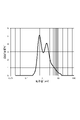
- 1 is a diagram showing measurement results of particle size distribution in Example 1.
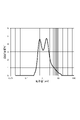
- FIG. FIG. 10 is a diagram showing the measurement results of the particle size distribution of Comparative Example 2; It is a graph which shows the relationship between H1/H0 of each Example and each Example, and the viscosity of a slurry.
- the silicon nitride powder according to this embodiment contains primary particles of silicon nitride.
- aggregated particles in which the primary particles are aggregated may be included.
- the primary particles and aggregated particles may also have oxides such as silicon dioxide on their surfaces.
- the purity of silicon nitride in the silicon nitride powder may be 98% by mass or higher, or may be 99% by mass or higher.
- FIG. 1 is a diagram showing an example of volume-based particle size distribution of silicon nitride powder measured with a particle size distribution measuring device using a laser diffraction/scattering method.
- the horizontal axis is the particle size [ ⁇ m] on a logarithmic scale, and the vertical axis is the frequency [% by volume].
- the particle size distribution in the present disclosure is measured according to the method described in JIS Z 8825:2013 "Particle Size Analysis-Laser Diffraction/Scattering Method”. Ultrasonic dispersion is performed as a pretreatment for measurement. Specifically, 60 mg of silicon nitride powder is weighed into a 500 mL container.
- a 20% aqueous solution of sodium hexametaphosphate (20 mL) and water (200 g) are added as a dispersant to obtain a measurement sample.
- the container containing the measurement sample is set in an ultrasonic dispersion machine manufactured by Sharp Corporation, and ultrasonically dispersed for 1 minute. Particle size distribution measurement is performed using the dispersion liquid obtained by such pretreatment.
- LS-13 320 (trade name) manufactured by Beckman Coulter is used for particle size distribution measurement.
- the particle refractive index is 2.2 and the solvent refractive index is 1.33.
- the particle size distribution measured under the above conditions has a first peak 10 and a second peak 20 in a particle size region larger than the first peak 10.
- a first peak 10 indicates the particle size of the primary particles of silicon nitride.
- the particle diameter d1 of the first peak 10 (primary particles) may be 0.2 to 1.0 ⁇ m.
- the lower limit of the particle diameter d1 may be 0.3 ⁇ m, 0.4 ⁇ m, or 0.5 ⁇ m from the viewpoint of ease of production.
- the upper limit of the particle diameter d1 may be 0.9 ⁇ m, 0.8 ⁇ m, or 0.7 ⁇ m from the viewpoint of improving sinterability.
- the second peak 20 indicates the particle size of the primary particles and aggregated particles formed by aggregating the primary particles.
- the particle size d2 of the second peak 20 (apex) may be greater than 1.5 ⁇ m and less than 4.0 ⁇ m.
- the lower limit of the particle diameter d2 may be 1.6 ⁇ m, 1.7 ⁇ m, or 1.8 ⁇ m from the viewpoint of improving sinterability.
- the upper limit of the particle diameter d2 may be 3.5 ⁇ m, 3.0 ⁇ m, or 2.5 ⁇ m from the viewpoint of improving sinterability.
- the particle diameter d0 of the valley bottom 30 between the first peak 10 and the second peak 20 may exceed 1.0 ⁇ m and be 1.5 ⁇ m or less.
- the lower limit of the particle diameter d0 may be 1.1 ⁇ m.
- the upper limit of the particle diameter d0 may be 1.3 ⁇ m.
- the particle size at which the detector of the particle size distribution measuring device manufactured by Beckman Coulter, trade name: LS-13 320 is switched included. Therefore, it is possible to clarify the boundary between the primary particles and the aggregated particles, and to obtain an index of how much of the aggregated particles has a relatively small diameter.
- the particle size d0 may be the particle size at which the detector switches.
- H1/H0 is 1.6 or more.
- the silicon nitride powder in which the ratio (H1/H0) of the height H1 of the first peak to the lowest height H0 of the valley bottom 30 is a predetermined value or more has a sufficient proportion of primary particles of silicon nitride that are not agglomerated. expensive. Since such a silicon nitride powder has excellent sinterability, it can be suitably used as a raw material for a silicon nitride sintered body. From the viewpoint of further reducing aggregated particles, H1/H0 may be 1.7 or more, or 1.75 or more.
- H1/H0 may be 2.5 or 2.0 from the viewpoint of ease of preparation.
- H1/H0 can be adjusted, for example, by the pulverization conditions in the pulverization step and the classification conditions in the classification step when manufacturing the silicon nitride powder.
- the frequency of the lowest height H0 may be 0.1 to 6.0% by volume, or may be 1.0 to 5.0% by volume.
- the height H1 of the first peak may be 4.0-8.0% by volume, or 4.8-7.0% by volume.
- H1 and H0 can be adjusted, for example, by the pulverization conditions in the pulverization step and the classification conditions in the classification step when manufacturing the silicon nitride powder.
- the minimum height H0 that is, the difference (d0-d1) between the particle diameter d0 of the valley bottom 30 and the particle diameter d1 of the first peak 10 may be 0.6 ⁇ m or less, 0.55 ⁇ m or less, and 0.55 ⁇ m or less. It may be 5 ⁇ m or less.
- Such a silicon nitride powder has a narrow particle size range of the first peak 10 and a sharp particle size distribution. Therefore, when used as a raw material for a silicon nitride sintered body, a sufficiently densified silicon nitride sintered body can be obtained.
- the lower limit of the difference (d0-d1) may be 0.1 ⁇ m or 0.2 ⁇ m from the viewpoint of ease of manufacture.
- the difference (d2-d1) between the particle size d2 of the second peak and the particle size d1 of the first peak 10 may be 2.0 ⁇ m or less, may be 1.5 ⁇ m or less, or may be 1.4 ⁇ m or less. good too.
- a silicon nitride powder since the difference in particle size between the first peak 10 and the second peak is small, agglomerated particles once generated are easily pulverized into primary particles. For this reason, the ratio of primary particles to aggregated particles is sufficiently high. Therefore, when used as a raw material for a silicon nitride sintered body, a sufficiently densified silicon nitride sintered body can be obtained.
- the lower limit of the difference (d2-d1) may be 0.4 ⁇ m or 0.6 ⁇ m from the viewpoint of ease of manufacture.
- the average particle size (D50, median size) of the silicon nitride powder obtained from the particle size distribution may be 0.8 to 1.8 ⁇ m. If such a silicon nitride powder is used as a raw material for a silicon nitride sintered body, the thermal conductivity and mechanical properties of the silicon nitride sintered body can be further improved. From the same point of view, the average particle size may be 1.0 to 1.6 ⁇ m, or 1.1 to 1.5 ⁇ m.
- the upper limit of the BET specific surface area of the silicon nitride powder may be, for example, 5.0 to 9.0 m 2 /g, 6.0 to 8.0 m 2 /g, 6.4 to 7.0 m 2 /g. It may be 5 m 2 /g.
- the BET specific surface area of the silicon nitride powder may be adjusted, for example, by changing the grinding conditions or the like during production of the silicon nitride powder.
- the BET specific surface area in the present disclosure conforms to the method described in JIS Z 8830:2013 "Method for measuring specific surface area of powder (solid) by gas adsorption" and is a value measured by the BET single-point method using nitrogen gas. is.
- the surface oxygen content of the silicon nitride powder may be 3.0% by mass or less, 2.5% by mass or less, or 2.2% by mass or less. When the surface oxygen content of the silicon nitride powder is within the above range, the grain boundary phase can be sufficiently reduced when the silicon nitride sintered body is produced.
- the surface oxygen content of the silicon nitride powder may be 0.2% by mass or more, or may be 0.5% by mass or more. When the surface oxygen content of the silicon nitride powder is within the above range, grain growth can be promoted when the silicon nitride powder is fired.
- the "surface oxygen content" in the present disclosure is obtained by the following procedure.
- a commercially available oxygen/nitrogen analyzer is used for the measurement.
- the measurement procedure is as follows. A sample for measurement is heated from 20° C. to 2000° C. at a heating rate of 8° C./second in a helium gas atmosphere. Oxygen desorbed with temperature rise is detected by an infrared absorption method. At the beginning of the temperature rise, oxygen bound to the surface of the silicon nitride powder is desorbed. When it is further heated and the temperature reaches around 1400° C., the silicon nitride begins to decompose. Nitrogen is detected when the silicon nitride decomposes. After this, oxygen inside the silicon nitride powder is desorbed. Therefore, the amount of oxygen detected after nitrogen starts to be detected corresponds to the amount of internal oxygen. Therefore, the amount of oxygen detected and quantified before nitrogen begins to be detected is the amount of surface oxygen in the present disclosure.
- the moisture content of the silicon nitride powder measured at 120°C may be 0.4% by mass or less, 0.3% by mass or less, or 0.2% by mass or less. By lowering the moisture content of the silicon nitride powder measured at 120° C., aggregation of the primary particles of silicon nitride can be suppressed.
- the moisture content of the silicon nitride powder may be 0.05% by mass or more, or may be 0.1% by mass or more, from the viewpoint of ease of production.
- the moisture content of the silicon nitride powder measured at 500°C may be 0.5% by mass or less, 0.4% by mass or less, or 0.3% by mass or less.
- a silicon nitride powder having such a low moisture content as measured at 500° C. has a high degree of purity. Therefore, for example, the thermal conductivity and mechanical properties of a silicon nitride sintered body can be further increased.
- Moisture content measured at 120°C moisture content 1
- Moisture content measured at 500°C moisture content 2
- Moisture content 1 is determined by weighing an empty weighing bottle, adding 5 g of a silicon nitride powder sample, and measuring the total weight of the weighing bottle and the sample. This is dried for 3 hours in a dryer set at 120°C. After drying, place the weighing bottle in a desiccator and cool. Then weigh and divide the weight loss of the sample by the initial weight of the sample. This value is the moisture content of 1.
- the moisture content 2 is measured using a Karl Fischer moisture meter.
- a Karl Fischer moisture meter As for the measurement method, an empty sample board is set in the combustion tube and the temperature is raised to 500° C. to perform blank measurement. A sample of silicon nitride powder of 0.9 to 1.0 g is then weighed onto the sample board of the apparatus and set in the combustion tube. The temperature is raised to 500° C. and the water content is analyzed and divided by the initial weight. This value is the moisture content of 2.
- the viscosity (30 rpm) at 25° C. of the slurry obtained by mixing the silicon nitride powder and water at a mass ratio of 1:1 may be 10 Pa s or less, and may be 8.0 Pa s or less. , 6.0 Pa ⁇ s or less, or 5.0 Pa ⁇ s or less.
- a slurry having such a low viscosity is excellent in dispersibility of the silicon nitride powder, which is a solid content. Therefore, when the silicon nitride sintered body is produced by the wet molding process, it is possible to sufficiently reduce variations in the properties of the silicon nitride sintered body. Therefore, a silicon nitride sintered body having high thermal conductivity and mechanical properties can be stably produced.
- the viscosity (60 rpm) at 25° C. of the slurry obtained by mixing the silicon nitride powder and water at a mass ratio of 1:1 may be 6.0 Pa s or less, and may be 5.0 Pa • s or less, 4.0 Pa ⁇ s or less, or 3.0 Pa ⁇ s or less.
- the viscosity (30 rpm) of the slurry at 25°C may be 1.0 Pa ⁇ s or more, or may be 2.0 Pa ⁇ s or more.
- the viscosity (60 rpm) of the slurry at 25° C. may be 0.5 Pa ⁇ s or more, or may be 1.0 Pa ⁇ s or more.
- the viscosity of the slurry changes depending on the aggregation state of the primary particles of silicon nitride. That is, the silicon nitride powder in which the primary particles of silicon nitride are suppressed from agglomerating can reduce the viscosity of the slurry. Therefore, by using a silicon nitride powder capable of reducing the viscosity of the slurry, it is possible to sufficiently reduce the variation in the properties of the silicon nitride sintered body even in the dry molding process. Therefore, any process can stably produce a silicon nitride sintered body having high thermal conductivity and mechanical properties.
- Slurry viscosity in the present disclosure is measured by the following procedure. Water and silicon nitride powder are blended at a mass ratio of 1:1, and stirred manually until the powder does not settle at the bottom of the container. This disperses the silicon nitride powder in the water.
- the viscosity of the prepared slurry is measured using a commercially available B-type viscometer. Viscosity is measured at 25° C. and at predetermined rotation speeds (30 rpm and 60 rpm). As the B-type viscometer, TVB-10 (trade name) manufactured by Toki Sangyo Co., Ltd. can be used.
- the method for producing a silicon nitride powder of this example includes a firing step of firing a silicon powder in an atmosphere containing nitrogen and at least one selected from the group consisting of hydrogen and ammonia to obtain a fired product; It has a pulverization step of dry-pulverizing a material to obtain a pulverized material, and a classification step of dry-classifying the pulverized material.
- silicon powder with a low oxygen concentration may be used.
- the oxygen concentration of the silicon powder may be, for example, 0.40% by mass or less, 0.30% by mass or less, or 0.20% by mass or less.
- the lower limit of the oxygen concentration of the silicon powder may be, for example, 0.10% by mass or 0.15% by mass.
- the silicon powder may have an oxygen concentration of, for example, 0.10 to 0.40% by mass. Incidentally, the oxygen concentration of the silicon powder can be measured by an infrared absorption method.
- silicon powder may be used, or one prepared by a reaction may be used.
- a pretreatment liquid containing hydrofluoric acid can be used to reduce the amount of oxygen bound to the silicon powder.
- the silicon powder may be pretreated with a pretreatment liquid containing hydrofluoric acid to obtain a silicon powder having an oxygen concentration of 0.4% by mass.
- the pretreatment liquid may contain hydrofluoric acid.
- the pretreatment liquid may be, for example, a mixed acid with an acid such as hydrochloric acid, or may consist of only hydrofluoric acid.
- the temperature of the pretreatment liquid in the pretreatment step may be, for example, 40 to 80°C.
- the contact time between the pretreatment liquid and the silicon powder may be, for example, 1 to 10 hours.
- the silicon powder is fired in a mixed atmosphere containing nitrogen and at least one selected from the group consisting of hydrogen and ammonia to obtain a fired product containing silicon nitride.
- the total content of hydrogen and ammonia in the mixed atmosphere may be, for example, 10-40% by volume based on the entire mixed atmosphere.
- the firing temperature may be, for example, 1100-1450°C, or 1200-1400°C.
- the firing time may be, for example, 30-100 hours.
- the fired product obtained in the firing step is dry-pulverized to obtain a pulverized product.
- the pulverization process may be divided into multiple stages such as coarse pulverization and fine pulverization.
- the milling process may include two stages, a ball milling process and a vibratory milling process.
- the filling rate of balls in the container in the ball milling process may be 30 to 70% by volume.
- the lower limit of the ball filling rate in the container may be, for example, 50% by volume or 60% by volume based on the volume of the container.
- the upper limit of the ball filling rate in the container may be, for example, 65% by volume based on the volume of the container.
- the grinding treatment time (grinding time) in the ball mill grinding step may be 5 to 15 hours, or may be 8 to 12 hours. As a result, the aggregated particles can be made sufficiently fine while suppressing excessive pulverization.
- the pulverized material obtained in the ball mill pulverization step may be further pulverized by the vibration mill pulverization step.
- the filling rate of the balls in the container in the vibratory milling process may be 50 to 80% by volume, or may be 60 to 75% by volume.
- the grinding treatment time (grinding time) in the vibration mill grinding step may be 8 to 20 hours, or may be 12 to 17 hours.
- the pulverized material obtained in the pulverization step is dry-classified to obtain a silicon nitride powder having a desired particle size distribution.
- a silicon nitride powder having a desired particle size distribution.
- at least some of the agglomerated particles can be excluded to adjust the particle size distribution of the silicon nitride powder.
- Dry classification can be performed by air classification or the like.
- the airflow classifier can be classified by using a whirling airflow type using secondary air. As such an air classifier, for example, DS-10 (trade name) manufactured by Nippon Pneumatic Industry Co., Ltd. may be used.
- the primary air pressure (inlet pressure) may be, for example, 0.2-0.8 MPa, or 0.3-0.7 MPa.
- the primary air volume may be 1-4 m 3 /min, or 2-3 m 3 /min.
- the clearance of the secondary air intake may be 25-45 mm, and may be 30-40 mm.
- the mixing ratio (powder/air amount) will decrease, and the ratio of aggregated particles on the fine powder side can be reduced. That is, it is possible to reduce the proportion of agglomerated particles contained in the silicon nitride powder recovered as fine powder. If the amount of air is reduced by reducing the clearance of the secondary air intake port within the above range, the mixing ratio (powder/air amount) will be reduced and the proportion of aggregated particles on the fine powder side will be increased. That is, the proportion of aggregated particles contained in the silicon nitride powder recovered as fine powder increases.
- the ratio of the silicon nitride powder after classification (after removal of coarse particles) to the total amount of pulverized powder before the classification step may be 40 to 60% by mass, and may be 45 to 55% by mass. If this ratio is lowered, the content of aggregated particles can be further lowered. That is, the peak height ratio (H1/H0) can be further reduced. On the other hand, if the above ratio is increased, the manufacturing cost of the silicon nitride powder can be reduced.
- the silicon nitride powder of the present embodiment can be produced through the above steps.
- the manufacturing method described above is an example, and is not limited to this.
- the silicon nitride powder of the present embodiment has reduced agglomerated particles, and is therefore excellent in sinterability. Therefore, silicon nitride powder may be used as a raw material for sintering.
- An embodiment of the method for producing a silicon nitride sintered body has a step of molding and firing the sintering raw material containing the silicon nitride powder described above.
- the raw material for sintering may contain an oxide-based sintering aid in addition to the silicon nitride powder.
- oxide-based sintering aids include Y 2 O 3 , MgO and Al 2 O 3 .
- the content of the oxide-based sintering aid in the raw material for sintering may be, for example, 3 to 10% by mass.
- the above sintering raw material is pressed with a molding pressure of, for example, 3.0 to 30 MPa to obtain a compact.
- the compact may be produced by uniaxial pressing or may be produced by CIP. Moreover, you may bake while shape
- the firing temperature may be 1860-2100°C, or 1880-2000°C.
- the firing time at the firing temperature may be 6 to 20 hours, or 8 to 16 hours.
- the heating rate to the firing temperature may be, for example, 1.0 to 10.0° C./hour.
- the obtained silicon nitride sintered body has reduced coarse grains and has a fine structure with excellent uniformity. Moreover, since it has a sufficiently dense structure, it is excellent in thermal conductivity and mechanical properties. In addition, since variation in particle size is reduced, variation in properties of the silicon nitride sintered body can be reduced.
- Example 1 ⁇ Preparation of Silicon Nitride Powder> A compact (bulk density: 1.4 g/cm 3 ) was produced using silicon powder. The obtained compact was placed in an electric furnace and fired at 1400° C. for 60 hours to produce a fired body containing silicon nitride. A mixed gas of nitrogen and hydrogen (a mixed gas in which N 2 and H 2 are mixed in a volume ratio of 80:20 in a standard state) was supplied as an atmosphere during firing. After roughly pulverizing the obtained sintered body, it was dry-pulverized with a ball mill. In the pulverization by the ball mill, the filling rate of the balls in the container was set to 60% by volume, and the pulverization time was set to 8 hours. Furthermore, the dry-pulverized material was dry-pulverized by a vibrating mill, and the filling rate of the balls to the container was set to 70% by volume, and the pulverization time was set to 15 hours.
- a mixed gas of nitrogen and hydrogen a mixed gas in which N 2 and H 2
- the silicon nitride powder obtained by dry pulverization was classified using a classifier (trade name: DS-10, manufactured by Nippon Pneumatic Industry Co., Ltd.). Classification conditions were as follows. Primary air pressure: 0.4 MPa Primary air volume: 2 m 3 /min Secondary air intake clearance: 30mm
- Coarse particles were removed from the silicon nitride powder by classification.
- the mass ratio of the silicon nitride powder after classification to the total mass of the silicon nitride powder before classification was 43% by mass.
- the classified silicon nitride powder means a silicon nitride powder obtained by removing coarse particles (aggregated particles). The same applies to the following examples and comparative examples.
- the silicon nitride powder thus obtained was evaluated as follows.
- the particle size distribution of the silicon nitride powder was measured by laser diffraction/scattering method. The measurement was performed according to the method described in JIS Z 8825:2013 "Particle size analysis-laser diffraction/scattering method". Particle size distribution was measured by weighing 60 mg of silicon nitride powder into a 500 mL container. To this, a 20% aqueous solution of sodium hexametaphosphate (2 mL) and water (200 g) were blended as dispersants. This container was set in an ultrasonic dispersion machine manufactured by Sharp Corporation so that the entire portion containing the dispersion liquid was immersed, and ultrasonic dispersion was performed for 1 minute. The above-described particle size distribution measurement was performed using the sample after ultrasonic dispersion. The measured particle size distribution was as shown in FIG.
- the smaller particle size is referred to as the first peak
- the larger particle size is referred to as the second peak.
- Table 1 shows the particle diameter d0 at the bottom of the valley between the first peak and the second peak and the frequency at the bottom of the valley (minimum height H0).
- the particle diameter d1 and the frequency of the first peak (height H1)
- the ratio of the height H1 to the lowest height H0 H1/H0
- the difference between the particle diameter d0 and the particle diameter d1 (d0-d1)
- the second Table 1 shows the peak particle size d2 and the difference (d2-d1) between the particle size d2 and the particle size d1.
- the average particle size was as shown in Table 2.
- the BET specific surface area was measured according to JIS Z 8803:2013 by the BET single-point method using nitrogen gas. The results were as shown in Table 2.
- the surface oxygen content was measured using an oxygen/nitrogen analyzer (manufactured by Horiba, Ltd., device name: EMGA-920). Specifically, the silicon nitride powder was heated from 20° C. to 2000° C. at a heating rate of 8° C./sec in a helium atmosphere, and the amount of oxygen was measured before nitrogen was detected. The results were as shown in Table 2.
- Example 2 A silicon nitride powder was prepared in the same manner as in Example 1, except that the classification conditions were changed as follows. The mass ratio of the silicon nitride powder after classification to the total mass of the silicon nitride powder before classification was 45% by mass. The same measurements as in Example 1 were performed on the obtained silicon nitride powder. The results were as shown in Tables 1 and 2. Primary air pressure: 0.4 MPa Primary air volume: 2 m 3 /min Secondary air intake clearance: 35mm
- Example 3 A silicon nitride powder was prepared in the same manner as in Example 1, except that the classification conditions were changed as follows. The mass ratio of the silicon nitride powder after classification to the total mass of the silicon nitride powder before classification was 48% by mass. Each measurement was performed in the same manner as in Example 1 for the obtained silicon nitride powder. The results were as shown in Tables 1 and 2. Primary air pressure: 0.4 MPa Primary air volume: 2 m 3 /min Secondary air intake clearance: 40mm
- Example 1 A silicon nitride powder was prepared in the same manner as in Example 1, except that the classification conditions were changed as follows. The mass ratio of the silicon nitride powder after classification to the total mass of the silicon nitride powder before classification was 62% by mass. Each measurement was performed in the same manner as in Example 1 for the obtained silicon nitride powder. The results were as shown in Tables 1 and 2. Primary air pressure: 0.4 MPa Primary air volume: 2 m 3 /min Secondary air intake clearance: 55mm
- Example 2 A silicon nitride powder was prepared in the same manner as in Example 1, except that the classification conditions were changed as follows. The mass ratio of the silicon nitride powder after classification to the total mass of the silicon nitride powder before classification was 64% by mass. Each measurement was performed in the same manner as in Example 1 for the obtained silicon nitride powder. The results were as shown in Tables 1 and 2. The measured particle size distribution was as shown in FIG. Primary air pressure: 0.2 MPa Primary air volume: 1 m 3 /min Secondary air intake clearance: 55mm
- Example 3 A silicon nitride powder was prepared in the same manner as in Example 1, except that the classification conditions were changed as follows. The mass ratio of the silicon nitride powder after classification to the total mass of the silicon nitride powder before classification was 65% by mass. Each measurement was performed in the same manner as in Example 1 for the obtained silicon nitride powder. The results were as shown in Tables 1 and 2. Primary air pressure: 0.2 MPa Primary air volume: 1 m 3 /min Secondary air intake clearance: 60mm
- FIG. 4 is a graph showing the relationship between the peak ratio (H1/H0) of each example and each comparative example and the slurry viscosity.
- a low-viscosity slurry can be prepared using the silicon nitride powder of each example.
- a silicon nitride powder in which aggregation of primary particles of silicon nitride is sufficiently suppressed is provided. Also, by using such a silicon nitride powder, a method for producing a silicon nitride sintered body having excellent properties is provided.
Landscapes
- Chemical & Material Sciences (AREA)
- Organic Chemistry (AREA)
- Engineering & Computer Science (AREA)
- Ceramic Engineering (AREA)
- Inorganic Chemistry (AREA)
- Manufacturing & Machinery (AREA)
- Materials Engineering (AREA)
- Structural Engineering (AREA)
- Ceramic Products (AREA)
Priority Applications (1)
| Application Number | Priority Date | Filing Date | Title |
|---|---|---|---|
| JP2022554356A JP7242972B2 (ja) | 2021-03-30 | 2022-03-23 | 窒化ケイ素粉末、及び窒化ケイ素焼結体の製造方法 |
Applications Claiming Priority (2)
| Application Number | Priority Date | Filing Date | Title |
|---|---|---|---|
| JP2021057685 | 2021-03-30 | ||
| JP2021-057685 | 2021-03-30 |
Publications (1)
| Publication Number | Publication Date |
|---|---|
| WO2022210209A1 true WO2022210209A1 (ja) | 2022-10-06 |
Family
ID=83456783
Family Applications (1)
| Application Number | Title | Priority Date | Filing Date |
|---|---|---|---|
| PCT/JP2022/013707 Ceased WO2022210209A1 (ja) | 2021-03-30 | 2022-03-23 | 窒化ケイ素粉末、及び窒化ケイ素焼結体の製造方法 |
Country Status (2)
| Country | Link |
|---|---|
| JP (1) | JP7242972B2 (https=) |
| WO (1) | WO2022210209A1 (https=) |
Cited By (1)
| Publication number | Priority date | Publication date | Assignee | Title |
|---|---|---|---|---|
| WO2026005005A1 (ja) * | 2024-06-28 | 2026-01-02 | Ube株式会社 | 3d造形用窒化ケイ素粉末、樹脂組成物、前駆体、窒化ケイ素質焼結体、物品、樹脂組成物の製造方法、および窒化ケイ素質焼結体の製造方法 |
Citations (4)
| Publication number | Priority date | Publication date | Assignee | Title |
|---|---|---|---|---|
| JP2002265276A (ja) * | 2001-03-07 | 2002-09-18 | Hitachi Metals Ltd | 窒化ケイ素粉末および窒化ケイ素焼結体 |
| CN102206082A (zh) * | 2011-03-03 | 2011-10-05 | 北方民族大学 | 一种制备亚微米氮化硅的方法 |
| JP2013203613A (ja) * | 2012-03-29 | 2013-10-07 | Ube Industries Ltd | 窒化ケイ素粉末の管理方法 |
| JP2016003157A (ja) * | 2014-06-16 | 2016-01-12 | 宇部興産株式会社 | 多結晶シリコンインゴット鋳造用鋳型の離型剤用窒化ケイ素粉末及びその製造方法、多結晶シリコンインゴット鋳造用鋳型の離型剤用窒化ケイ素粉末含有スラリー、ならびに多結晶シリコンインゴット鋳造用鋳型及びその製造方法 |
Family Cites Families (1)
| Publication number | Priority date | Publication date | Assignee | Title |
|---|---|---|---|---|
| JP3438928B2 (ja) * | 1994-01-12 | 2003-08-18 | 電気化学工業株式会社 | 窒化珪素粉末の製造方法 |
-
2022
- 2022-03-23 JP JP2022554356A patent/JP7242972B2/ja active Active
- 2022-03-23 WO PCT/JP2022/013707 patent/WO2022210209A1/ja not_active Ceased
Patent Citations (4)
| Publication number | Priority date | Publication date | Assignee | Title |
|---|---|---|---|---|
| JP2002265276A (ja) * | 2001-03-07 | 2002-09-18 | Hitachi Metals Ltd | 窒化ケイ素粉末および窒化ケイ素焼結体 |
| CN102206082A (zh) * | 2011-03-03 | 2011-10-05 | 北方民族大学 | 一种制备亚微米氮化硅的方法 |
| JP2013203613A (ja) * | 2012-03-29 | 2013-10-07 | Ube Industries Ltd | 窒化ケイ素粉末の管理方法 |
| JP2016003157A (ja) * | 2014-06-16 | 2016-01-12 | 宇部興産株式会社 | 多結晶シリコンインゴット鋳造用鋳型の離型剤用窒化ケイ素粉末及びその製造方法、多結晶シリコンインゴット鋳造用鋳型の離型剤用窒化ケイ素粉末含有スラリー、ならびに多結晶シリコンインゴット鋳造用鋳型及びその製造方法 |
Cited By (1)
| Publication number | Priority date | Publication date | Assignee | Title |
|---|---|---|---|---|
| WO2026005005A1 (ja) * | 2024-06-28 | 2026-01-02 | Ube株式会社 | 3d造形用窒化ケイ素粉末、樹脂組成物、前駆体、窒化ケイ素質焼結体、物品、樹脂組成物の製造方法、および窒化ケイ素質焼結体の製造方法 |
Also Published As
| Publication number | Publication date |
|---|---|
| JP7242972B2 (ja) | 2023-03-20 |
| JPWO2022210209A1 (https=) | 2022-10-06 |
Similar Documents
| Publication | Publication Date | Title |
|---|---|---|
| TWI788533B (zh) | 氮化矽粉末之製造方法 | |
| JPWO2011081103A1 (ja) | ジルコニア−アルミナ複合セラミック材料の製造方法、ジルコニア−アルミナ複合造粒粉、ジルコニアビーズ | |
| JP2025143538A (ja) | 窒化ケイ素粉末、及び窒化ケイ素焼結体の製造方法 | |
| WO2021210507A1 (ja) | 焼結用窒化ケイ素粉末 | |
| JP7242972B2 (ja) | 窒化ケイ素粉末、及び窒化ケイ素焼結体の製造方法 | |
| JP7223918B1 (ja) | 窒化ケイ素粉末、及び窒化ケイ素焼結体の製造方法 | |
| JP7598363B2 (ja) | 窒化ケイ素粉末、及び窒化ケイ素焼結体の製造方法 | |
| WO2021200830A1 (ja) | 窒化ケイ素粉末、及び窒化ケイ素焼結体の製造方法 | |
| KR20070040356A (ko) | 질화알루미늄 분말의 제조 방법 | |
| JP2004182554A (ja) | ジルコニア粉末 | |
| JP7171973B1 (ja) | 窒化ケイ素粉末、スラリー、及び窒化ケイ素焼結体の製造方法 | |
| JP7640530B2 (ja) | 窒化ケイ素粉末、及び窒化ケイ素焼結体の製造方法 | |
| JP3900589B2 (ja) | 珪窒化マグネシウム粉末及びその製造方法 | |
| JP2024010444A (ja) | 焼結用窒化ケイ素粉末 | |
| JP2680681B2 (ja) | 窒化アルミニウム粉末の製造方法 | |
| WO2025205634A1 (ja) | 窒化ケイ素粉末、及びその製造方法 | |
| WO2021200814A1 (ja) | 窒化ケイ素粉末、及び窒化ケイ素焼結体の製造方法 | |
| JP2008137838A (ja) | アルミナ粉末及びその製造方法 | |
| JP2024021564A (ja) | 窒化ケイ素粉末の製造方法 | |
| WO2025205635A1 (ja) | 窒化ケイ素粉末 | |
| Yokota et al. | Influence of starting particle size of alumina powder prepared by grinding on the size of platelike grain in the respective sintered bodies | |
| WO2025206127A1 (ja) | 結晶質窒化ケイ素粉末、窒化ケイ素質焼結体および窒化ケイ素質焼結体の製造方法 | |
| WO2025205632A1 (ja) | 窒化ケイ素粉末、及びその製造方法 | |
| WO2024195299A1 (ja) | 窒化ケイ素粉末の製造方法、及び、窒化ケイ素焼結体の製造方法 | |
| JP2025156831A (ja) | 窒化ケイ素粉末 |
Legal Events
| Date | Code | Title | Description |
|---|---|---|---|
| ENP | Entry into the national phase |
Ref document number: 2022554356 Country of ref document: JP Kind code of ref document: A |
|
| 121 | Ep: the epo has been informed by wipo that ep was designated in this application |
Ref document number: 22780423 Country of ref document: EP Kind code of ref document: A1 |
|
| NENP | Non-entry into the national phase |
Ref country code: DE |
|
| 122 | Ep: pct application non-entry in european phase |
Ref document number: 22780423 Country of ref document: EP Kind code of ref document: A1 |