WO2022209908A1 - 振動アクチュエータ - Google Patents
振動アクチュエータ Download PDFInfo
- Publication number
- WO2022209908A1 WO2022209908A1 PCT/JP2022/011995 JP2022011995W WO2022209908A1 WO 2022209908 A1 WO2022209908 A1 WO 2022209908A1 JP 2022011995 W JP2022011995 W JP 2022011995W WO 2022209908 A1 WO2022209908 A1 WO 2022209908A1
- Authority
- WO
- WIPO (PCT)
- Prior art keywords
- leaf spring
- case
- vibration
- vibration actuator
- damping
- Prior art date
- Legal status (The legal status is an assumption and is not a legal conclusion. Google has not performed a legal analysis and makes no representation as to the accuracy of the status listed.)
- Ceased
Links
Images




Classifications
-
- H—ELECTRICITY
- H02—GENERATION; CONVERSION OR DISTRIBUTION OF ELECTRIC POWER
- H02K—DYNAMO-ELECTRIC MACHINES
- H02K5/00—Casings; Enclosures; Supports
- H02K5/24—Casings; Enclosures; Supports specially adapted for suppression or reduction of noise or vibrations
-
- B—PERFORMING OPERATIONS; TRANSPORTING
- B06—GENERATING OR TRANSMITTING MECHANICAL VIBRATIONS IN GENERAL
- B06B—METHODS OR APPARATUS FOR GENERATING OR TRANSMITTING MECHANICAL VIBRATIONS OF INFRASONIC, SONIC, OR ULTRASONIC FREQUENCY, e.g. FOR PERFORMING MECHANICAL WORK IN GENERAL
- B06B1/00—Methods or apparatus for generating mechanical vibrations of infrasonic, sonic, or ultrasonic frequency
- B06B1/02—Methods or apparatus for generating mechanical vibrations of infrasonic, sonic, or ultrasonic frequency making use of electrical energy
- B06B1/04—Methods or apparatus for generating mechanical vibrations of infrasonic, sonic, or ultrasonic frequency making use of electrical energy operating with electromagnetism
-
- H—ELECTRICITY
- H02—GENERATION; CONVERSION OR DISTRIBUTION OF ELECTRIC POWER
- H02K—DYNAMO-ELECTRIC MACHINES
- H02K33/00—Motors with reciprocating, oscillating or vibrating magnet, armature or coil system
- H02K33/02—Motors with reciprocating, oscillating or vibrating magnet, armature or coil system with armatures moved one way by energisation of a single coil system and returned by mechanical force, e.g. by springs
-
- H—ELECTRICITY
- H02—GENERATION; CONVERSION OR DISTRIBUTION OF ELECTRIC POWER
- H02K—DYNAMO-ELECTRIC MACHINES
- H02K33/00—Motors with reciprocating, oscillating or vibrating magnet, armature or coil system
- H02K33/16—Motors with reciprocating, oscillating or vibrating magnet, armature or coil system with polarised armatures moving in alternate directions by reversal or energisation of a single coil system
Definitions
- the present invention relates to a vibration actuator, and more particularly to a vibration actuator that supports a mover with leaf springs.
- vibration notification method using a vibration actuator (or vibration motor) as a method of notifying people of incoming calls and alarms.
- vibration actuators are used as one of the effects of action scenes and feedback means for players. Reality is improved by stimulating the sense of touch.
- Some vibration actuators use a method of rotating an eccentric weight with a motor to generate vibration by inertial force.
- the method using a rotary motor has the disadvantage that the inertial force of the eccentric weight generates vibration, so the reaction from the start of rotation of the eccentric weight until the vibration is felt as a tactile sensation is dull, impairing reality.
- a voice coil type actuator may be adopted.
- a mover having a magnet is arranged in a cylindrical case, a coil fixed to the case is arranged around the mover, and the mover is moved inside the case by energizing the coil. It is reciprocating.
- a disk-shaped leaf spring having a plurality of arms is used to support the mover so as to reciprocate with respect to the case.
- the plate spring is provided with a damping member for controlling the vibration characteristics thereof.
- the vibration damping member is formed along the shape of the leaf spring, and the leaf spring and the vibration damping member are arranged in such a manner that there is no deviation between the leaf spring and the damping member.
- the damping part is fixed on the spring by sticking it with an adhesive or the like. That is, when the shape and fixing of the leaf spring and the damping member are misaligned, the damping member protruding from the arm portion of the leaf spring to the plane perpendicular to the vibration axis direction acts as a resistance, and the amplitude of the mover is reduced. adversely affect the Therefore, the damping member must be precisely formed along the arm of the leaf spring. is required.
- the mover is supported by the case on the fixed side via the leaf spring.
- the relationship will differ from product to product, resulting in non-uniform vibration characteristics of the leaf spring.
- the vibration axis of the mover is used as a reference, if the case and the leaf spring are misaligned or loose in the vibration axis direction, the pressure applied to the leaf spring in the axial direction becomes uneven, resulting in deformation of the leaf spring. Disparities occur from time to time.
- the present invention has been proposed to solve the problems of the prior art as described above. SUMMARY OF THE INVENTION It is an object of the present invention to provide a vibration actuator that facilitates assembly work of leaf springs and damping members and has excellent vibration characteristics.
- the vibration actuator of the present invention has the following configuration.
- Case. (2) a coil provided in the case; (3) A mover that vibrates along the vibration axis of the case. (4) A leaf spring whose inner periphery is fixed to the mover. (5) A frame that fixes the leaf spring to the case. (6) The frame includes a fixing portion provided on the outer peripheral portion of the leaf spring and a damping portion provided on the vibrating portion of the leaf spring.
- the frame portion and the leaf spring are molded.
- the fixed portion is provided with an engaging portion that engages with the engaged portion on the case side.
- the vibration damping portion is configured by a protruding portion that protrudes inward from the inner diameter of the case, and a plurality of the protruding portions are provided.
- the leaf spring has an annular inner peripheral portion to which the mover is attached, an outer peripheral portion attached to the damping portion, and a plurality of spiral arms connecting the inner peripheral portion and the outer peripheral portion. It has (5)
- the damping section is fixed to the arm section by molding.
- the arm has a through hole or notch.
- the damping section covers the leaf spring.
- the frame includes the engaging portion where a portion of the leaf spring is exposed, and the exposed portion of the leaf spring is in contact with the axial positioning portion of the case. (9)
- the frame has a front surface and/or a back surface knurled.
- FIG. 2 is a cross-sectional view taken in the vibration axis direction showing the overall configuration of the first embodiment; It is an exploded perspective view showing the whole composition of a 1st embodiment.
- 4 is a perspective view of the inside of the cover case in the first embodiment;
- FIG. 4 is an exploded perspective view of a case body and a yoke in the first embodiment;
- FIG. It is an exploded perspective view of a coil and a bobbin in a 1st embodiment.
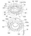
- 4 is an exploded perspective view of a leaf spring and a frame portion in the first embodiment;
- FIG. 4A and 4B are a horizontal cross-sectional view and a vertical cross-sectional view of a leaf spring and a frame portion according to the first embodiment;
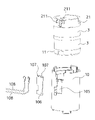
- FIG. 4 is an exploded perspective view showing a structure for fixing a leaf spring and a frame portion to a case body in the first embodiment;
- FIG. 3 is an exploded perspective view showing a coil, a bobbin, and terminals arranged on a case body in the first embodiment;
- FIG. 11 is an exploded perspective view showing the overall configuration of another embodiment of the present invention
- 4A and 4B are a horizontal cross-sectional view and a vertical cross-sectional view of a leaf spring and a frame portion showing another embodiment of the present invention
- 4A and 4B are a horizontal cross-sectional view and a vertical cross-sectional view of a leaf spring and a frame portion showing another embodiment of the present invention
- FIG. 1 The vibration actuator 1 of the first embodiment will be described below with reference to FIGS. 1 and 2.
- FIG. The vibration actuator 1 of the present embodiment is provided with members of the same shape bounded by a plane of symmetry (symbol S in FIG. 1) perpendicular to the central axis at a half of the vibration axis O direction. Accordingly, with respect to the configuration of each member, only one symmetrical configuration will be described, and the description of the other members will be omitted by denoting the same reference numerals unless there is a particular need.
- the vibration actuator 1 mainly includes a cylindrical case 2 forming an outer shell, a coil 3 provided inside the case 2, and a mover that vibrates along the vibration axis O of the case 2. 4 , a leaf spring 5 whose inner peripheral portion is fixed to the mover 4 , and a frame portion 6 for fixing the leaf spring 5 to the case 2 .
- the case 2 includes a cylindrical case body 10 and a cover case 11 that closes the openings at both ends.
- a flange portion 102 protruding radially inward of the case body 10 is provided on the end face of the case body 10 having a cylindrical shape.
- the flange portion 102 has a spiral inner edge portion having three stepped portions 102a in accordance with the shape of the plate spring 5 having spiral arm portions.
- Three locking claws 101 are provided on the surface of the flange portion 102 at intervals of 120 degrees and extend in the direction of the vibration axis O from the open end of the case body 10 .
- the bases of the three locking claws 101 protrude inward from the edge of the opening of the case body 10 and serve as engaged portions for positioning the frame 6 in the circumferential direction.
- the surface of the flange portion 102 is provided with an axial positioning portion 103 for the frame portion 6 .
- the positioning portion 103 protrudes from the surface of the flange portion 102 in the vicinity of the locking claw 101 in this embodiment. Further, the surface of the positioning portion 103 is a portion that contacts the bottom surface of the leaf spring 5 .
- the cover case 11 is provided with three locking holes 111 on the outer peripheral side, which are engaged with three locking claws 101 protruding from the opening of the case body 10 . Both are fixed by being combined.
- the case main body 10 and the cover case 11 are made of a resin material such as ABS, but are not limited to the resin material.
- a coil 3 and a yoke 20 are inserted into the case 2 .
- a cylindrical yoke 20 made of a soft magnetic material is arranged along the inner periphery of the case body 10 .
- a coil 3 is provided on the inner circumference of the yoke 20 so as to be electrically insulated from the yoke 20 .
- the coil 3 is wound along the outer peripheral side concave portion of the bobbin 21 and arranged with a predetermined distance from the outer peripheral portion of the mover 4 .
- the bobbin 21 has an inner peripheral wall on the inner periphery of the case body 10 so as to cover the surface of the coil 3 on the mover 4 side.
- a gap is provided between the inner peripheral wall of and the outer peripheral surface of the mover 4 .
- the coil 3 can generate a magnetic field when energized from the terminal 106 .
- the coil 3 may be temporarily fixed to the yoke 20 and the bobbin 21 with an adhesive or the like during assembly.
- the mover 4 is arranged in the case body 10 so as to vibrate along the vibration axis O, which is the direction of the central axis of the cylindrical case 2 .
- the mover 4 includes a disk-shaped magnet 30 , a disk-shaped pole piece 31 arranged on the surface of the magnet 30 , and a weight 32 arranged on the surface of the pole piece 31 . have.
- the direction of magnetization of the magnet 30 is the direction of the vibration axis O.
- the pole piece 31 is made of a soft magnetic material and attached to the magnet 30 by the magnetic attraction force of the magnet 30, an adhesive, or the like. As shown in FIG. 6, the pole piece 31 has a convex portion 311 along the vibration axis O at its center, and the corresponding weight 32 has a concave portion 321 along the vibration axis O at its center. It is The pole piece 31 and the weight 32 are integrated by engaging the projection 311 of the pole piece 31 with the recess 321 of the weight 32 .
- this integration does not require that the convex portion 311 of the pole piece 31 and the concave portion 321 of the weight 32 are engaged with each other without a gap, but are loosely engaged with a gap between them.
- the degree of engagement does not matter.
- the integration of the magnet 30, the pole piece 31, and the weight 32 is not limited to attachment using a magnetic attraction force or adhesive, but can be achieved by fixing by mechanical means such as press-fitting, screwing, or other means. may be integrated.
- the outer shape of the magnet 30 is radially smaller than the outer shapes of the pole piece 31 and the weight 32. That is, the outer circumferences of the pole piece 31 and the weight 32 are located on the outermost side of the mover 4 and are closest to the inner circumference wall of the bobbin 21 .
- the weight 32 is made of a non-magnetic material and has a bell-shaped truncated cone portion 322 extending in the direction of the vibration axis O, and a disk-shaped bottom portion 323 extending from the bottom surface of the truncated cone portion 322 in the outer peripheral direction. ing.
- a center shaft 324 protruding in the direction of the vibration axis O is provided at the center of the tip of the truncated cone portion 322 of the weight 32 .
- the central axis 324 of the weight 32 is circular, is inserted into the shaft hole 50 of the leaf spring 5, and the leaf spring 5 and the weight 32 are fixed.
- the leaf spring 5 is composed of one or more metal leaf springs.
- a thin stainless steel plate is used.
- the material of the leaf spring 5 is not limited to metal, and may be a composite material containing resin or fiber. Moreover, the material of the leaf spring 5 is desirably a material having excellent durability and flexibility.
- a circular shaft hole 50 into which the central shaft 324 of the weight 32 is fitted is provided at the center of the inner circumference of the plate spring 5 .
- the plate spring 5 is connected to the weight 32 using the shaft hole 50 .
- the center shaft 324 protruding from the surface of the leaf spring 5 is heated and pressed by a jig and crushed, so that the surface of the weight 32 and the leaf spring 5 are crimped while being superimposed.
- the means for fixing the leaf spring 5 and the weight 32 is not limited to caulking, and if the circular center shaft 324 and the shaft hole 50 are provided, they can be fixed (connected) by other methods such as screwing or adhesion. You can also
- the plate spring 5 includes an annular inner peripheral portion 54 to which the mover 4 is attached, an outer peripheral portion 51 attached to the damping portion 62, and a plurality of springs connecting the inner peripheral portion 54 and the outer peripheral portion 51. It has spiral arms 52 . Each arm portion 52 is provided around the vibration axis O at equal intervals of 120 degrees. The outer peripheral portion 51 of each arm portion 52 is connected to the frame portion 6 that fixes the plate spring 5 to the case body 10 . Three through holes 53 are provided in the outer peripheral portion 51 .
- the frame 6 includes a fixing portion 61 for fixing the outer peripheral portion 51 of the leaf spring 5 to the case 2, and a damping portion provided on the vibrating portion of the leaf spring 5.
- a portion 62 is provided.
- the fixing portion 61 has a shape along the inner circumference of the case body 10 and has a substantially annular shape.
- a recessed portion 611 recessed toward the inner peripheral side is formed in the outer peripheral portion of the fixed portion 61 .
- this concave portion 611 engages with engaged portions provided at the bases of the three locking claws 101 provided on the case body 10 to position the frame portion 6 in the circumferential direction. It constitutes an engaging portion for performing.
- the shape of the engaging portion and the engaged portion is not limited to the shape of the present embodiment as long as they engage with each other, and the number of them can be increased or decreased as necessary.
- steps 61a are provided in accordance with the shape of the plate spring 5 having the spiral arms 52, similar to the flange portion 102 of the case body 10.
- a portion of the outer peripheral portion 51 of the leaf spring 5 is exposed at the portion 61a.
- the exposed portion of the leaf spring 5 corresponds to the "exposed portion” in the claims. More specifically, as shown in FIG. 9 , a concave portion 611 provided on the outer periphery of the frame portion 6 is provided with an exposed portion where a portion of the outer peripheral portion 51 of the leaf spring 5 is exposed. The exposed portion provided in this concave portion 611 abuts on the axial positioning portion 103 provided in the case main body 10 .
- the damping portion 62 that controls vibration characteristics is configured by a protruding portion that protrudes inward from the inner diameter of the case body 10 .
- the shape, location and number of protruding portions are not limited.
- a plurality of vibration damping portions 62 are provided at equal intervals, and three vibration damping portions 62 are provided in accordance with the number of arm portions 52 of the leaf spring 5 .
- the width and height of the damping portion 62 are formed in a region where mechanical resistance can be applied to the plate spring 5 and optimum vibration characteristics can be obtained.
- the fixing portion 61 and the damping portion 62 may be formed integrally or separately by molding.
- the frame portion 6 and the leaf spring 5 are integrated by molding. That is, by placing the leaf spring 5 in a mold and molding by pouring resin, the frame portion 6 is overmolded on both upper and lower surfaces of the leaf spring 5, so that the upper portion and the lower portion of the frame portion 6 are formed as leaf springs.
- the frame portion 6 and the plate spring 5 are integrally molded with the plate spring 5 sandwiched therebetween.
- the vibration damping portion 62 is molded and fixed to the arm portion 52 of the plate spring 5 .
- the dimensions and shape of the damping portion 62 such as the thickness, the amount of protrusion from the frame portion 6, the length in the circumferential direction, the number, etc., are set so that the leaf spring 5 exhibits desired vibration characteristics.
- an opening reaching the surface of the plate spring 5 is provided in the vibration damping portion 62, or an opening passing through the gap between the arm portions 52 of the plate spring 5 and reaching the back surface of the vibration damping portion 62 is provided.
- a plurality of bracket-like members protruding from the inner circumference of the frame portion 6 toward the center can be used.
- the tip of the vibration damping portion 62 is inserted into the groove between the arm portions 52 of the leaf spring 5, and the front and back sides of the arm portion 52 are clamped and fixed. It is not necessarily limited to such a configuration, and it may contact only one of the front surface and the back surface of the leaf spring 5 .
- the arm portion 52 is provided with a through hole 53 or a notch so that the resin forming the vibration damping portion 62 can be removed from the surface of the arm portion 52 . Since it smoothly flows into the rear surface, the adhesion between the damping portion 62 and the plate spring 5 can be improved.
- the frame part 6 has at least one of polyethylene and elastomer.
- Elastomers include, but are not limited to, thermoplastic polyurethane elastomers (TPU).
- TPU thermoplastic polyurethane elastomers
- the vibration of the leaf spring 5 is damped by elastic deformation of the frame 6, specifically shear deformation of polyethylene, bending deformation of elastomer, and the like.
- the fixed part 61 and the damping part 62 can be made of the same resin material, the fixed part 61 is made of a hard resin that is less elastically deformable, and the damping part 62 is made of an elastic material such as elastomer. is also possible. Further, a reinforcing member made of metal or resin may be molded around the frame portion 6 in addition to the plate spring 5 .
- the leaf spring 5 configured in this manner is elastically deformable within a predetermined range in cross directions including the direction of the vibration axis O and the radial direction S perpendicular to the vibration axis O.
- This predetermined range corresponds to the amplitude range of the mover 4 when the vibration actuator 1 is normally used. Therefore, the predetermined range is at least a range in which the leaf spring 5 does not contact the case 2 and does not exceed the elastic deformation limit of the leaf spring 5 . Since the leaf spring 5 has three spiral arm portions 52, when the leaf spring 5 is deformed to the maximum extent, the cross section of the leaf spring 5 forms a mountain shape in which the central portion protrudes most in the direction of the vibration axis O.
- the amount of deformation is smaller at the portion where the leaf spring 5 and the frame portion 6 are fixed, that is, at the outer periphery of the leaf spring 5 . Therefore, even if the frame portion 6 and the flange portion 102 of the case main body 10 have stepped portions 61a and 102a, respectively, and the shape of the inner periphery is spiral-like, the case 2 may be deformed when the plate spring 5 is deformed. There is no contact with the stepped portions 61a and 102a protruding toward the center (vibration axis O).
- terminals 211 for connecting the lead wires of the coils 3 to the bobbin 21 are integrally fixed by molding.
- a flat terminal fixing portion 105 is provided on the outer peripheral surface of the case body 10 so as to match the position of the terminal 211, and a terminal 106 made of a printed wiring board is fixed to this fixing portion 105.
- the fixing means of the terminal 106 and the fixing portion 105 may be fixed by molding the terminal 106 to the case body 10 or by ultrasonic welding.
- the terminal 106 is provided with a connector recess 107 into which the terminal 211 is fitted, and a power wire 108 for supplying power to the vibration actuator 1 is connected by means of soldering or the like. It should be noted that the terminal 106 made of a printed wiring board does not necessarily have to be provided, and the power supply wire 108 may be directly connected to the terminal 211 for connecting the lead wire of each coil 3 .
- alternating current is applied to the coil 3 via the terminal 106 in a direction that alternately generates magnetic fields of opposite polarities.
- the same polarity is generated in adjacent portions of the coil 3 .
- the mover 4 generates thrust to one side in the direction of the vibration axis O, and if the current flowing to the coil 3 is reversed, the mover 4 will move to the other side in the direction of the vibration axis O. Thrust is generated.
- the movable element 4 vibrates along the vibration axis O while receiving the biasing force of the plate spring 5 from both sides.
- the frame portion 6 damps the vibration of the leaf spring 5 by its elastic deformation, specifically shear deformation of polyethylene or bending deformation of an elastomer.
- the thrust generated in the mover 4 basically follows the thrust given based on Fleming's left-hand rule.
- a thrust force is generated as a reaction force of the force generated in the two coils 3 in the mover 4 to which the magnet 30 and the like are attached. also occurs.
- the vibration actuator 1 of this embodiment having such a configuration incorporates the bobbin 21 with the coil 3 mounted inside the case body 10 in which the yoke 20 is integrated. Insert 4.
- the plate spring 5 molded on the frame portion 6 is fixed to the central axis 324 of the weight 32 of the mover 4 by caulking or other means, and the mover 4 fixed to the plate spring 5 is is inserted inside the bobbin 21.
- the fixing portion 61 of the frame portion 6 is superimposed on the flange portion 102 of the case body 10 so that the locking claws 101 of the case body 10 are fitted into the recesses 611 of the frame portion 6 , and the frame is mounted inside the case body 10 . Fit the part 6. In this way, the concave portion 611 and the base portion of the locking claw 101 mesh with each other as the engaging portion and the engaged portion, and the frame portion 6 is positioned in the circumferential direction. At the same time, the plate spring 5 exposed in the recess 611 contacts the positioning portion 103 provided on the flange portion 102, and the plate spring 5 is positioned in the axial direction.
- the cover case 11 is placed over the opening of the case body 10 and pressurized so that the three locking claws 101 are fitted into the three locking holes 111, and the cover case 11 and the case body are separated. Both are fixed by ultrasonically welding 10 .
- the frame portion 6 and the cover case 11 are welded together. During this time, the adhesion between the frame portion 6 and the case body 10 can be ensured.
- the vibration actuator 1 according to the present embodiment is provided in advance with the frame portion 6 having the plate spring 5, the fixing portion 61, and the damping portion 62. As shown in FIG. This eliminates the need to temporarily fix the plate spring 5 to the case body 10 , and the three members can be assembled to the case 2 only by fixing the frame portion 6 to the case body 10 . This simplifies assembly work and improves work efficiency.
- the frame portion 6 and the plate spring 5 are integrated by molding. Therefore, positioning of the leaf spring 5 with respect to the frame portion 6 and positioning of the vibration damping portion 62 with respect to the leaf spring 5 can be performed accurately and easily simply by setting the leaf spring 5 in a mold and molding. Further, it becomes possible to directly and firmly attach the vibration damping member to the plate spring 5, thereby preventing damage and peeling of the vibration damping member.
- the fixed portion 61 of the frame portion 6 is formed toward the inner circumference, and the concave portion 611 that engages with the base portion of the locking claw 101 of the case body 10 is provided.
- the frame portion 6 having the damping portion 62 and the plate spring 5 are formed in advance, the engaged portion of the case body 10 and the recessed portion 611 provided in the frame portion 6 are engaged.
- the frame portion 6 having the leaf spring 5 and the damping portion 62 is assembled to the case body 10 at the same time. Therefore, the positioning between the case body 10 and the frame portion 6 can be performed accurately and easily, and the assembling work can be simplified.
- the damping portions 62 protrude inward from the inner diameter of the case main body 10 and are provided at regular intervals. Therefore, by adjusting the width and height of the damping portion 62, it becomes easy to adjust the damping area suitable for the size, weight and material of each member. Further, by providing the damping portions 62 at regular intervals, a stable damping effect can be exhibited.
- the vibration damping portion 62 is fixed to the outer peripheral portion 51 of the leaf spring 5 by overmolding the resin of the frame portion 6 onto the arm portion 52 of the leaf spring 5 . . Therefore, it is possible to obtain the mechanical resistance of the mover 4 by utilizing the loss of the resin material, thereby suppressing the amplitude at the maximum acceleration frequency. In addition, it is possible to suppress the sharpness of the resonance peak and suppress the change in acceleration due to the change in resonance frequency. As a result, it is possible to prevent the damping member from being damaged or peeled off, and to improve the durability of the vibration actuator 1 .
- the vibration actuator 1 according to the present embodiment is provided with the concave portion 611 in the frame portion 6 from which a part of the leaf spring 5 is exposed, and the surface of the leaf spring 5 contacts the axial positioning portion 103 of the case body 10. there is Therefore, when performing alignment in the axial direction, it is possible to accurately align the case body 10 with the leaf spring 5 and the frame portion 6 using the surface of the leaf spring 5 as a reference.
- the frame portion 6 is made of polyethylene or elastomer. Therefore, the plate spring 5 is fixed to the case body 10 as the fixing portion 61 of the frame portion 6, and at the same time, the damping portion 62 damps the vibration of the plate spring 5 by shear deformation of polyethylene or bending deformation of the elastomer. be able to.
- the frame portion 6 is not limited to being made of polyethylene or elastomer, and similar materials may be used.
- the bobbin 21 is provided with the terminals 211 for connecting the lead wires of the coils 3, thereby facilitating the work of connecting the lead wires from the coils 3 to the terminals 106.
- FIG. 1 the lead wire of the coil 3 is thinner than the metal bar forming the terminal 211, and must be handled with the utmost care. Such a problem can be solved by connecting the coil 3 and the terminal 106 via.
- the frame portion 6 and the leaf spring 5 are integrated by molding, but they may be integrated by joining, fitting, or the like.
- the fixing portion 61 and the damping portion 62 of the frame portion 6 are not limited to being made of the same material, and may be made of different materials and then integrated.
- the upper and lower portions of the frame portion 6 that sandwiches the plate spring 5 may be made of the same material, or may be made of a different material.
- the concave portion 611 is used as an engaging portion and also as an exposed portion for the plate spring 5.
- the engaging portion for positioning the plate spring 5 and the frame portion 6 in the circumferential direction and the The exposed portions of the plate springs 5 for positioning the direction may be provided at different locations.
- the case main body 10 may be provided with the engaging holes and the cover case 11 may be provided with the engaging claws.
- the plate spring 5 has three arm portions 52 and three damping portions 62, but the number is not limited.
- the case 2 has a cylindrical shape
- the mover 4 has a substantially cylindrical shape. Other shapes may be used.
- the plate spring 5 that supports the mover 4 has the spiral arm portion 52, but other plate springs may be used.
- irregular spiral leaf springs, cross-shaped leaf springs, or swastika-shaped leaf springs that combine straight lines as well as curves may be used.
- the inner guide also has a shape along the shape of the leaf spring.
- the tip central portion of the truncated cone portion 322 of the weight 32 is not limited to the central shaft 324, and a central hole may be provided.
- the leaf spring 5 and the weight 32 may be fixed by inserting a pin from the opening side of the case body 10 into the stop hole and the shaft hole 50 of the leaf spring 5 .
- the central axis 324 is not limited to a circular shape, and may be other polygonal shapes such as a triangle and a quadrangle.
- FIG. 11 is an exploded perspective view showing the overall configuration of an embodiment in which the coil 3 is not provided with the bobbin 21. As shown in FIG. The coil 3 is fixed to the yoke 20 with an adhesive or the like so as to be arranged with a predetermined distance from the outer circumference of the mover 4 . In this embodiment, since the coil 3 is not provided with the bobbin 21, a more compact design is possible.
- FIG. 12 is a horizontal cross-sectional view and a vertical cross-sectional view of the leaf spring 5 and the frame portion 6, showing an embodiment having 53 on the inner peripheral portion 54 of the leaf spring 5.
- FIG. In this embodiment, along the shape of the inner peripheral portion 54 of the arm portion 52, there are three substantially triangular through holes 53 with rounded corners. Note that the shape, number, and locations of the through holes 53 are not limited to these.
- the margin of load stress in the radial direction (horizontal direction) of the leaf spring 5 can be increased. Therefore, in the present embodiment, it is possible to prevent the leaf spring 5 from having a stress concentration portion and exhibit a stable vibration damping effect.
- the through hole 53 in the inner peripheral portion 54 by providing the through hole 53 in the inner peripheral portion 54, the margin of load displacement of the plate spring 5 in the amplitude direction (vertical direction) can be increased. Therefore, compared to the case where the through hole 53 is not provided in the inner peripheral portion 54, it becomes easier to lower the rigidity of the leaf spring 5 itself, and a wide range of vibration output designs are possible.
- FIG. 13 is a horizontal sectional view and a longitudinal sectional view of the leaf spring 5 and the frame portion 6 showing an embodiment in which the front and back surfaces of the frame portion 6 are knurled.
- knurling can increase the frictional force on the front and back surfaces of the frame portion 6 . Therefore, when the frame portion 6 is fixed to the case main body 10 and the cover case 11, it is possible to prevent both from slipping and to be less likely to come off, compared to the case where the knurling is not performed.
- the present invention is not limited to this, and may be projections and depressions in which a large number of peaks and valleys are alternately provided by knurling, or small projections. It may be unevenness provided with a large number of. Graining, blasting, or the like may be used instead of knurling. Further, only one of the front surface and the back surface of the frame portion 6 may be knurled, or the outer periphery of the fixed portion 61 of the frame portion 6 may be knurled.
Landscapes
- Engineering & Computer Science (AREA)
- Power Engineering (AREA)
- Physics & Mathematics (AREA)
- Electromagnetism (AREA)
- Mechanical Engineering (AREA)
- Reciprocating, Oscillating Or Vibrating Motors (AREA)
- Apparatuses For Generation Of Mechanical Vibrations (AREA)
Priority Applications (3)
| Application Number | Priority Date | Filing Date | Title |
|---|---|---|---|
| US18/284,529 US20240186875A1 (en) | 2021-03-30 | 2022-03-16 | Vibration actuator |
| JP2023510916A JP7850137B2 (ja) | 2021-03-30 | 2022-03-16 | 振動アクチュエータ |
| CN202280013965.7A CN116829273A (zh) | 2021-03-30 | 2022-03-16 | 振动致动器 |
Applications Claiming Priority (2)
| Application Number | Priority Date | Filing Date | Title |
|---|---|---|---|
| JP2021057490 | 2021-03-30 | ||
| JP2021-057490 | 2021-03-30 |
Publications (1)
| Publication Number | Publication Date |
|---|---|
| WO2022209908A1 true WO2022209908A1 (ja) | 2022-10-06 |
Family
ID=83459082
Family Applications (1)
| Application Number | Title | Priority Date | Filing Date |
|---|---|---|---|
| PCT/JP2022/011995 Ceased WO2022209908A1 (ja) | 2021-03-30 | 2022-03-16 | 振動アクチュエータ |
Country Status (4)
| Country | Link |
|---|---|
| US (1) | US20240186875A1 (https=) |
| JP (1) | JP7850137B2 (https=) |
| CN (1) | CN116829273A (https=) |
| WO (1) | WO2022209908A1 (https=) |
Cited By (1)
| Publication number | Priority date | Publication date | Assignee | Title |
|---|---|---|---|---|
| WO2024101363A1 (ja) * | 2022-11-08 | 2024-05-16 | フォスター電機株式会社 | アクチュエータ |
Families Citing this family (1)
| Publication number | Priority date | Publication date | Assignee | Title |
|---|---|---|---|---|
| CN115051525B (zh) * | 2022-06-30 | 2025-04-04 | 瑞声光电科技(常州)有限公司 | 线性振动马达 |
Citations (3)
| Publication number | Priority date | Publication date | Assignee | Title |
|---|---|---|---|---|
| JP2000354829A (ja) * | 1999-04-13 | 2000-12-26 | Tokin Corp | 振動アクチュエータ |
| JP2009033864A (ja) * | 2007-07-26 | 2009-02-12 | Mitsumi Electric Co Ltd | 振動発生装置 |
| KR20110083333A (ko) * | 2010-01-14 | 2011-07-20 | 주식회사 우성지앤티 | 선형 진동모터 |
Family Cites Families (52)
| Publication number | Priority date | Publication date | Assignee | Title |
|---|---|---|---|---|
| US5973422A (en) * | 1998-07-24 | 1999-10-26 | The Guitammer Company | Low frequency vibrator |
| JP4899076B2 (ja) * | 1999-04-16 | 2012-03-21 | 並木精密宝石株式会社 | 振動アクチュエータ及びその給電機構 |
| US6501357B2 (en) * | 2000-03-16 | 2002-12-31 | Quizix, Inc. | Permanent magnet actuator mechanism |
| WO2004036723A1 (ja) * | 2002-10-16 | 2004-04-29 | Matsushita Refrigeration Company | リニアモータとそれを用いたリニアコンプレッサ |
| US7538463B2 (en) * | 2006-01-10 | 2009-05-26 | Citizen Electronics Co., Ltd. | Vibrator |
| GB2438255B (en) * | 2006-02-23 | 2009-10-21 | Citizen Electronics | Vibrator |
| GB2439411B (en) * | 2007-04-27 | 2008-07-23 | Perpetuum Ltd | An electromechanical generator for converting mechanical vibrational energy into electrical energy |
| GB2446685B (en) * | 2007-11-27 | 2009-04-01 | Perpetuum Ltd | An electromechanical generator for converting mechanical vibrational energy into electrical energy |
| GB2459269B (en) * | 2008-04-15 | 2010-09-29 | Perpetuum Ltd | An electromechanical generator for, and method of, converting mechanical vibrational energy into electrical energy |
| US20110133577A1 (en) * | 2008-08-18 | 2011-06-09 | In Ho Lee | Horizontal linear vibration device |
| JP2010069356A (ja) * | 2008-09-16 | 2010-04-02 | Sanyo Electric Co Ltd | 往復振動器 |
| IT1391362B1 (it) * | 2008-10-06 | 2011-12-13 | Encrea S R L | Generatore miniaturizzato a magneti oscillanti per la produzione di energia elettrica da vibrazioni |
| JP2010104864A (ja) * | 2008-10-28 | 2010-05-13 | Sanyo Electric Co Ltd | 往復振動発生器 |
| US7948124B1 (en) * | 2009-01-28 | 2011-05-24 | The United States Of America As Represented By The Secretary Of The Navy | Electro-magnetic kinetic energy harvesting device using increased magnetic edge area |
| JP2011067082A (ja) * | 2009-08-19 | 2011-03-31 | Sanyo Electric Co Ltd | 扁平形振動モータ |
| GB2469347B (en) * | 2009-08-26 | 2011-10-05 | Perpetuum Ltd | An electromechanical generator for converting mechanical vibrational energy into electrical energy |
| KR101113561B1 (ko) * | 2010-02-08 | 2012-02-24 | 삼성전기주식회사 | 수직진동자 |
| JP5659426B2 (ja) * | 2010-02-16 | 2015-01-28 | 日本電産セイミツ株式会社 | 振動発生装置 |
| JP5537984B2 (ja) * | 2010-02-16 | 2014-07-02 | 日本電産セイミツ株式会社 | 往復振動発生器 |
| CN103026062A (zh) * | 2010-06-07 | 2013-04-03 | 动态能源技术有限责任公司 | 转动动能转换系统 |
| US9356499B2 (en) * | 2010-11-30 | 2016-05-31 | Seiko Instruments Inc. | Electromagnetic generator |
| KR101354744B1 (ko) * | 2011-08-04 | 2014-01-23 | 삼성전기주식회사 | 선형진동장치 |
| EP2584683B1 (en) * | 2011-10-21 | 2020-03-18 | Université de Liège | Energy harvesting system using several energy sources. |
| JP6036143B2 (ja) * | 2012-10-11 | 2016-11-30 | ミツミ電機株式会社 | 発電装置 |
| KR101969438B1 (ko) * | 2012-11-12 | 2019-04-16 | 주식회사 엠플러스 | 선형진동모터 |
| KR102030597B1 (ko) * | 2013-03-15 | 2019-11-08 | 주식회사 엠플러스 | 진동발생장치 및 이를 구비하는 전자장치 |
| JP6439145B2 (ja) * | 2013-11-07 | 2018-12-19 | パナソニックIpマネジメント株式会社 | 発電装置 |
| JP6023691B2 (ja) * | 2013-11-18 | 2016-11-09 | 日本電産コパル株式会社 | 振動アクチュエータ |
| US9562525B2 (en) * | 2014-02-10 | 2017-02-07 | Haier Us Appliance Solutions, Inc. | Linear compressor |
| US20150330449A1 (en) * | 2014-05-15 | 2015-11-19 | Aktiebolaget Skf | Method for manufacturing a rolling bearing and rolling bearing manufactured according to such a method |
| JP6396129B2 (ja) * | 2014-09-05 | 2018-09-26 | 日本電産コパル株式会社 | リニア振動モータの製造方法 |
| JP6715101B2 (ja) * | 2016-06-20 | 2020-07-01 | 株式会社東芝 | 振動発電機、振動発電ユニット、振動発電モジュールおよび電気機器 |
| US10622538B2 (en) * | 2017-07-18 | 2020-04-14 | Apple Inc. | Techniques for providing a haptic output and sensing a haptic input using a piezoelectric body |
| JP6911145B2 (ja) * | 2017-11-20 | 2021-07-28 | アルプスアルパイン株式会社 | 振動発生装置 |
| JP6980877B2 (ja) * | 2017-12-25 | 2021-12-15 | フォスター電機株式会社 | 振動アクチュエータ |
| JP7137046B2 (ja) * | 2017-12-28 | 2022-09-14 | ミツミ電機株式会社 | 振動アクチュエーター及び携帯機器 |
| JP7157305B2 (ja) * | 2018-03-26 | 2022-10-20 | ミツミ電機株式会社 | 振動アクチュエータ及び電子機器 |
| GB2572350B (en) * | 2018-03-27 | 2023-01-25 | Hitachi Rail Ltd | An electromechanical generator for converting mechanical vibrational energy into electrical energy |
| GB2572348B (en) * | 2018-03-27 | 2020-08-19 | Perpetuum Ltd | An electromechanical generator for converting mechanical vibrational energy into electrical energy |
| GB2572351B (en) * | 2018-03-27 | 2020-08-26 | Perpetuum Ltd | An electromechanical generator for converting mechanical vibrational energy into electrical energy |
| JP7063691B2 (ja) * | 2018-04-06 | 2022-05-09 | フォスター電機株式会社 | 振動アクチュエータ |
| JP6900565B2 (ja) * | 2018-04-06 | 2021-07-07 | フォスター電機株式会社 | 振動アクチュエータ |
| EP4631630A3 (en) * | 2018-08-28 | 2025-11-05 | Minebea Mitsumi Inc. | Vibration actuator and electronic equipment |
| JP7291246B2 (ja) * | 2019-04-11 | 2023-06-14 | コンチネンタル・エンジニアリング・サーヴィシズ・ゲゼルシャフト・ミト・ベシュレンクテル・ハフツング | 自動車内での高性能低音再生のための剛構造体用の振動アクチュエータ |
| KR20210047576A (ko) * | 2019-10-22 | 2021-04-30 | 주식회사 씨케이머티리얼즈랩 | 래디얼 마그넷 액추에이터 |
| US12337346B2 (en) * | 2020-02-27 | 2025-06-24 | Minebea Mitsumi Inc. | Vibration actuator and electronic device |
| WO2021172576A1 (ja) * | 2020-02-27 | 2021-09-02 | ミネベアミツミ株式会社 | 振動アクチュエータ及び電子機器 |
| JP7410791B2 (ja) * | 2020-04-28 | 2024-01-10 | ニデックインスツルメンツ株式会社 | アクチュエータ |
| CN113572333B (zh) * | 2020-04-28 | 2024-03-29 | 日本电产三协株式会社 | 致动器 |
| JP2022049071A (ja) * | 2020-09-16 | 2022-03-29 | 株式会社東芝 | 振動発電機 |
| DE102020213768A1 (de) * | 2020-11-02 | 2022-05-05 | Continental Engineering Services Gmbh | Aktuator zur Anregung von Schwingungen umfassend einen Antrieb mit verbesserter Dämpfung |
| US11646680B2 (en) * | 2021-09-08 | 2023-05-09 | Honeywell International Inc. | Autonomous wireless multivariant sensor node—AWSN |
-
2022
- 2022-03-16 JP JP2023510916A patent/JP7850137B2/ja active Active
- 2022-03-16 US US18/284,529 patent/US20240186875A1/en active Pending
- 2022-03-16 CN CN202280013965.7A patent/CN116829273A/zh active Pending
- 2022-03-16 WO PCT/JP2022/011995 patent/WO2022209908A1/ja not_active Ceased
Patent Citations (3)
| Publication number | Priority date | Publication date | Assignee | Title |
|---|---|---|---|---|
| JP2000354829A (ja) * | 1999-04-13 | 2000-12-26 | Tokin Corp | 振動アクチュエータ |
| JP2009033864A (ja) * | 2007-07-26 | 2009-02-12 | Mitsumi Electric Co Ltd | 振動発生装置 |
| KR20110083333A (ko) * | 2010-01-14 | 2011-07-20 | 주식회사 우성지앤티 | 선형 진동모터 |
Cited By (1)
| Publication number | Priority date | Publication date | Assignee | Title |
|---|---|---|---|---|
| WO2024101363A1 (ja) * | 2022-11-08 | 2024-05-16 | フォスター電機株式会社 | アクチュエータ |
Also Published As
| Publication number | Publication date |
|---|---|
| US20240186875A1 (en) | 2024-06-06 |
| JPWO2022209908A1 (https=) | 2022-10-06 |
| JP7850137B2 (ja) | 2026-04-22 |
| CN116829273A (zh) | 2023-09-29 |
Similar Documents
| Publication | Publication Date | Title |
|---|---|---|
| JP4475993B2 (ja) | 多機能型振動アクチュエータ及び携帯端末機器 | |
| WO2022209908A1 (ja) | 振動アクチュエータ | |
| CN110212728A (zh) | 振动驱动器 | |
| JP5033667B2 (ja) | スピーカ | |
| CN113853734A (zh) | 致动器 | |
| JP2009028641A (ja) | 振動発生装置 | |
| JP7664696B2 (ja) | 振動アクチュエータ | |
| JP7560326B2 (ja) | 振動アクチュエータ | |
| CN113472171A (zh) | 致动器及减振单元 | |
| WO2022113819A1 (ja) | アクチュエータ | |
| JP2022076895A (ja) | 振動アクチュエータ | |
| WO2023243413A1 (ja) | 振動アクチュエータ | |
| JP7789524B2 (ja) | アクチュエータ | |
| JP2022076635A (ja) | 振動アクチュエータ | |
| JP2025003067A (ja) | 刺激付与装置及びウェアラブル装置 | |
| JP2022072473A (ja) | 振動アクチュエータ | |
| JP2021176637A (ja) | 振動アクチュエータ | |
| US20250183775A1 (en) | Vibrating motor | |
| KR20150025036A (ko) | 진동 발생 장치 | |
| JP7764198B2 (ja) | 振動アクチュエータ | |
| US12483106B2 (en) | Actuator with movable body and support body having magnets and yokes with different thicknesses | |
| JP7189303B2 (ja) | 振動アクチュエータ | |
| JP7598742B2 (ja) | アクチュエータ | |
| JP2024147152A (ja) | アクチュエータ | |
| KR101208737B1 (ko) | 진동자 장치 |
Legal Events
| Date | Code | Title | Description |
|---|---|---|---|
| 121 | Ep: the epo has been informed by wipo that ep was designated in this application |
Ref document number: 22780128 Country of ref document: EP Kind code of ref document: A1 |
|
| ENP | Entry into the national phase |
Ref document number: 2023510916 Country of ref document: JP Kind code of ref document: A |
|
| WWE | Wipo information: entry into national phase |
Ref document number: 202280013965.7 Country of ref document: CN |
|
| WWE | Wipo information: entry into national phase |
Ref document number: 18284529 Country of ref document: US |
|
| NENP | Non-entry into the national phase |
Ref country code: DE |
|
| 122 | Ep: pct application non-entry in european phase |
Ref document number: 22780128 Country of ref document: EP Kind code of ref document: A1 |