WO2022209784A1 - 無機粒子、無機粒子の製造方法、組成物、および、電子デバイスの製造方法 - Google Patents
無機粒子、無機粒子の製造方法、組成物、および、電子デバイスの製造方法 Download PDFInfo
- Publication number
- WO2022209784A1 WO2022209784A1 PCT/JP2022/011049 JP2022011049W WO2022209784A1 WO 2022209784 A1 WO2022209784 A1 WO 2022209784A1 JP 2022011049 W JP2022011049 W JP 2022011049W WO 2022209784 A1 WO2022209784 A1 WO 2022209784A1
- Authority
- WO
- WIPO (PCT)
- Prior art keywords
- inorganic particles
- composition
- shell portion
- less
- inorganic
- Prior art date
- Legal status (The legal status is an assumption and is not a legal conclusion. Google has not performed a legal analysis and makes no representation as to the accuracy of the status listed.)
- Ceased
Links
Classifications
-
- B—PERFORMING OPERATIONS; TRANSPORTING
- B22—CASTING; POWDER METALLURGY
- B22F—WORKING METALLIC POWDER; MANUFACTURE OF ARTICLES FROM METALLIC POWDER; MAKING METALLIC POWDER; APPARATUS OR DEVICES SPECIALLY ADAPTED FOR METALLIC POWDER
- B22F1/00—Metallic powder; Treatment of metallic powder, e.g. to facilitate working or to improve properties
-
- B—PERFORMING OPERATIONS; TRANSPORTING
- B22—CASTING; POWDER METALLURGY
- B22F—WORKING METALLIC POWDER; MANUFACTURE OF ARTICLES FROM METALLIC POWDER; MAKING METALLIC POWDER; APPARATUS OR DEVICES SPECIALLY ADAPTED FOR METALLIC POWDER
- B22F1/00—Metallic powder; Treatment of metallic powder, e.g. to facilitate working or to improve properties
- B22F1/14—Treatment of metallic powder
- B22F1/145—Chemical treatment, e.g. passivation or decarburisation
-
- B—PERFORMING OPERATIONS; TRANSPORTING
- B22—CASTING; POWDER METALLURGY
- B22F—WORKING METALLIC POWDER; MANUFACTURE OF ARTICLES FROM METALLIC POWDER; MAKING METALLIC POWDER; APPARATUS OR DEVICES SPECIALLY ADAPTED FOR METALLIC POWDER
- B22F1/00—Metallic powder; Treatment of metallic powder, e.g. to facilitate working or to improve properties
- B22F1/16—Metallic particles coated with a non-metal
-
- C—CHEMISTRY; METALLURGY
- C01—INORGANIC CHEMISTRY
- C01B—NON-METALLIC ELEMENTS; COMPOUNDS THEREOF; METALLOIDS OR COMPOUNDS THEREOF NOT COVERED BY SUBCLASS C01C
- C01B13/00—Oxygen; Ozone; Oxides or hydroxides in general
- C01B13/14—Methods for preparing oxides or hydroxides in general
-
- C—CHEMISTRY; METALLURGY
- C01—INORGANIC CHEMISTRY
- C01B—NON-METALLIC ELEMENTS; COMPOUNDS THEREOF; METALLOIDS OR COMPOUNDS THEREOF NOT COVERED BY SUBCLASS C01C
- C01B21/00—Nitrogen; Compounds thereof
- C01B21/06—Binary compounds of nitrogen with metals, with silicon, or with boron, or with carbon, i.e. nitrides; Compounds of nitrogen with more than one metal, silicon or boron
- C01B21/072—Binary compounds of nitrogen with metals, with silicon, or with boron, or with carbon, i.e. nitrides; Compounds of nitrogen with more than one metal, silicon or boron with aluminium
-
- C—CHEMISTRY; METALLURGY
- C01—INORGANIC CHEMISTRY
- C01B—NON-METALLIC ELEMENTS; COMPOUNDS THEREOF; METALLOIDS OR COMPOUNDS THEREOF NOT COVERED BY SUBCLASS C01C
- C01B33/00—Silicon; Compounds thereof
- C01B33/113—Silicon oxides; Hydrates thereof
- C01B33/12—Silica; Hydrates thereof, e.g. lepidoic silicic acid
- C01B33/18—Preparation of finely divided silica neither in sol nor in gel form; After-treatment thereof
-
- C—CHEMISTRY; METALLURGY
- C01—INORGANIC CHEMISTRY
- C01F—COMPOUNDS OF THE METALS BERYLLIUM, MAGNESIUM, ALUMINIUM, CALCIUM, STRONTIUM, BARIUM, RADIUM, THORIUM, OR OF THE RARE-EARTH METALS
- C01F7/00—Compounds of aluminium
- C01F7/02—Aluminium oxide; Aluminium hydroxide; Aluminates
- C01F7/021—After-treatment of oxides or hydroxides
-
- C—CHEMISTRY; METALLURGY
- C08—ORGANIC MACROMOLECULAR COMPOUNDS; THEIR PREPARATION OR CHEMICAL WORKING-UP; COMPOSITIONS BASED THEREON
- C08K—Use of inorganic or non-macromolecular organic substances as compounding ingredients
- C08K3/00—Use of inorganic substances as compounding ingredients
-
- C—CHEMISTRY; METALLURGY
- C08—ORGANIC MACROMOLECULAR COMPOUNDS; THEIR PREPARATION OR CHEMICAL WORKING-UP; COMPOSITIONS BASED THEREON
- C08K—Use of inorganic or non-macromolecular organic substances as compounding ingredients
- C08K9/00—Use of pretreated ingredients
- C08K9/04—Ingredients treated with organic substances
- C08K9/06—Ingredients treated with organic substances with silicon-containing compounds
-
- C—CHEMISTRY; METALLURGY
- C08—ORGANIC MACROMOLECULAR COMPOUNDS; THEIR PREPARATION OR CHEMICAL WORKING-UP; COMPOSITIONS BASED THEREON
- C08L—COMPOSITIONS OF MACROMOLECULAR COMPOUNDS
- C08L101/00—Compositions of unspecified macromolecular compounds
-
- C—CHEMISTRY; METALLURGY
- C23—COATING METALLIC MATERIAL; COATING MATERIAL WITH METALLIC MATERIAL; CHEMICAL SURFACE TREATMENT; DIFFUSION TREATMENT OF METALLIC MATERIAL; COATING BY VACUUM EVAPORATION, BY SPUTTERING, BY ION IMPLANTATION OR BY CHEMICAL VAPOUR DEPOSITION, IN GENERAL; INHIBITING CORROSION OF METALLIC MATERIAL OR INCRUSTATION IN GENERAL
- C23C—COATING METALLIC MATERIAL; COATING MATERIAL WITH METALLIC MATERIAL; SURFACE TREATMENT OF METALLIC MATERIAL BY DIFFUSION INTO THE SURFACE, BY CHEMICAL CONVERSION OR SUBSTITUTION; COATING BY VACUUM EVAPORATION, BY SPUTTERING, BY ION IMPLANTATION OR BY CHEMICAL VAPOUR DEPOSITION, IN GENERAL
- C23C16/00—Chemical coating by decomposition of gaseous compounds, without leaving reaction products of surface material in the coating, i.e. chemical vapour deposition [CVD] processes
- C23C16/22—Chemical coating by decomposition of gaseous compounds, without leaving reaction products of surface material in the coating, i.e. chemical vapour deposition [CVD] processes characterised by the deposition of inorganic material, other than metallic material
- C23C16/30—Deposition of compounds, mixtures or solid solutions, e.g. borides, carbides, nitrides
- C23C16/38—Borides
-
- C—CHEMISTRY; METALLURGY
- C01—INORGANIC CHEMISTRY
- C01B—NON-METALLIC ELEMENTS; COMPOUNDS THEREOF; METALLOIDS OR COMPOUNDS THEREOF NOT COVERED BY SUBCLASS C01C
- C01B21/00—Nitrogen; Compounds thereof
- C01B21/06—Binary compounds of nitrogen with metals, with silicon, or with boron, or with carbon, i.e. nitrides; Compounds of nitrogen with more than one metal, silicon or boron
- C01B21/064—Binary compounds of nitrogen with metals, with silicon, or with boron, or with carbon, i.e. nitrides; Compounds of nitrogen with more than one metal, silicon or boron with boron
Definitions
- the present invention relates to inorganic particles, inorganic particle production methods, compositions, and electronic device production methods.
- a filler used in an IC sealing material is required to be insulating and have high thermal conductivity.
- Materials that combine these properties include aluminum oxide (alumina), aluminum nitride, silicon nitride, and boron nitride.
- boron nitride is particularly excellent in thermal conductivity.
- Patent Document 1 since general boron nitride is scaly particles, orientation is likely to occur when mixed with resin or the like as a filler and molded, and anisotropy may occur in thermal conductivity. It has been pointed out that In order to solve this problem, Patent Document 1 discloses that core-shell type inorganic particles, which are inorganic particles coated with boron nitride, are used as a filler.
- the present invention provides a composition (especially a sheet-like composition) obtained by combining a resin or its precursor (especially a thermosetting resin) with excellent fluidity, and is obtained by curing the composition.
- An object of the present invention is to provide inorganic particles which have excellent thermal conductivity in a cured product and excellent insulation reliability in the cured product.
- Another object of the present invention is to provide a method for producing inorganic particles, a composition, and a method for producing an electronic device.
- the core portion contains at least one selected from the group consisting of silicon dioxide, aluminum oxide, aluminum nitride, and copper, wherein the shell portion contains boron nitride, Inorganic particles, wherein the content of iron atoms contained in the shell portion is 10 ppm by mass or less with respect to the total mass of the shell portion.
- [4] The inorganic particles of [3], wherein the D value is 0.005 or less.
- [5] The inorganic particles of [3] or [4], wherein the atomic ratio is 0.15 or more.
- [6] The inorganic particles according to any one of [3] to [5], wherein the atomic ratio is 0.25 or less.
- [7] The inorganic particles according to any one of [1] to [6], which have a median diameter of 300 ⁇ m or less.
- [8] The inorganic particles according to any one of [1] to [7], which have a median diameter of 100 ⁇ m or less.
- the particle size distribution curve representing the volume-based frequency distribution has peaks in the range of 1.0 to 50 ⁇ m, the range of 100 to 150 ⁇ m, and the range of 200 to 300 ⁇ m, respectively, of [1] to [8] Inorganic particles according to any one of the above.
- a method for producing the inorganic particles according to any one of [1] to [10] A method for producing inorganic particles, comprising a step of forming the shell portion by a vapor deposition method or a sputtering method.
- [12] A composition comprising the inorganic particles of any one of [1] to [10] and a resin or a precursor thereof. [13] The composition of [12], wherein the resin or its precursor is a thermosetting compound. [14] The composition according to [12] or [13], wherein the content of the inorganic particles is 45 to 60% by volume relative to the total solid content of the composition. [15] The composition according to any one of [12] to [14], which is in the form of a sheet. [16] A method for producing an electronic device, comprising the step of sealing a semiconductor member by compression molding using the composition according to [15].
- a composition obtained by combining a resin or a precursor thereof (especially a sheet-shaped composition) has excellent fluidity, and a cured product obtained by curing the composition has excellent thermal conductivity. Furthermore, it is possible to provide inorganic particles with excellent insulation reliability of the cured product. Moreover, according to the present invention, a method for producing inorganic particles, a composition, and a method for producing an electronic device can be provided.
- a numerical range represented by “to” means a range including the numerical values before and after “to” as lower and upper limits.
- ppm is an abbreviation for “parts per million” and means 10 ⁇ 6 .
- the “content” of the component means the total content of the two or more kinds of components.
- the inorganic particles of the present invention are spherical inorganic particles having a core portion and a shell portion, wherein the core portion is selected from the group consisting of silicon dioxide, aluminum oxide, aluminum nitride, and copper. At least one kind is included, the shell portion contains boron nitride, and the content of iron atoms contained in the shell portion is 10 mass ppm or less with respect to the total mass of the shell portion.
- the present inventors presume as follows. Since the inorganic particles of the present invention are spherical, the fluidity of a composition obtained by combining them with a resin or a precursor thereof (especially a sheet-like composition) is excellent. Moreover, since the inorganic particles of the present invention have boron nitride, which has excellent thermal conductivity, in the shell portion, the cured product obtained by curing the above composition has excellent thermal conductivity.
- the content of iron atoms contained in the shell portion of the inorganic particles of the present invention is 10 ppm by mass with respect to the total mass of the shell portion, the insulation reliability of the cured product is excellent.
- the composition obtained by combining the inorganic particles of the present invention with a resin or a precursor thereof has excellent fluidity, and the heat of the cured product obtained by curing the composition Satisfying any one or more of the better conductivity and the better insulation reliability of the cured product is also referred to as "the effect of the present invention is better."
- the requirements and preferable requirements satisfied by the inorganic particles of the present invention are described in detail below.
- the inorganic particles of the present invention are spherical.
- the inorganic particles being spherical means that the inorganic particles have an aspect ratio (the ratio of the major axis to the minor axis) of 1.00 to 1.10, and the aspect ratio is 1.00 to 1.08. is preferred.
- Examples of the method for measuring the aspect ratio of inorganic particles include a method using transmission electron microscopy or scanning electron microscopy.
- the distance between the two parallel lines selected so that the distance between the parallel lines is the maximum among the two parallel lines circumscribing the inorganic particles is the "major axis”. and Further, of the two parallel lines orthogonal to the two parallel lines that give the "major axis" and circumscribing the inorganic particles, between the two parallel lines selected so that the distance between the parallel lines is the smallest Let the distance be the "minor axis”. The aspect ratio (major axis/minor axis) of the inorganic particles is obtained from the obtained major axis and minor axis.
- the aspect ratio of the inorganic particles is calculated for at least 100 inorganic particles, the obtained aspect ratios are arithmetically averaged, and the obtained value is defined as the aspect ratio of the inorganic particles.
- the aspect ratio of inorganic particles can be measured using a scanning electron microscope "SU3900" manufactured by Hitachi High-Tech Science.
- the median diameter of the inorganic particles is not particularly limited, it is preferably 300 ⁇ m or less, more preferably 100 ⁇ m or less, and even more preferably 10 ⁇ m or less, from the viewpoint that the effects of the present invention are more excellent.
- the lower limit of the median diameter is not particularly limited, it is preferably 500 nm or more, more preferably 1.0 ⁇ m or more, and even more preferably 2.0 ⁇ m or more, from the viewpoint that the effects of the present invention are more excellent.
- the median diameter (D50) of inorganic particles can be measured using "Mastersizer 3000" manufactured by Malvern.
- Inorganic particles have peaks in the range of 1.0 to 50 ⁇ m, the range of 100 to 150 ⁇ m, and the range of 200 to 300 ⁇ m in the particle size distribution curve representing the volume-based frequency distribution, in that the effect of the present invention is more excellent. It is preferred to have When particles of a plurality of sizes are mixed in this manner, the inorganic particles are likely to be densely packed in the composition, and the effects of the present invention (in particular, thermal conductivity) are more excellent.
- the content of inorganic particles with a particle diameter of 1.0 to 50 ⁇ m is preferably 25 to 45% by volume with respect to the total volume of inorganic particles, and the content of inorganic particles with a particle diameter of 100 to 150 ⁇ m is preferably 25 to 45% by volume with respect to the total volume of inorganic particles. %, and the content of the inorganic particles having a particle diameter of 200 to 300 ⁇ m is preferably 15 to 35% by volume with respect to the total volume of the inorganic particles.
- Inorganic particles each having a peak in the above range can be obtained by mixing particles having a median diameter at each peak position.
- the inorganic particles have a core portion and a shell portion.
- the shell portion is arranged around the core portion so as to cover the core portion.
- the shell portion may be arranged so as to cover at least a portion of the core portion, and may be arranged so as to cover the entire surface of the core portion.
- the core portion contains at least one material selected from the group consisting of silicon dioxide, aluminum oxide, aluminum nitride, and copper (hereinafter also referred to as specific material).
- the specific material is preferably aluminum oxide, aluminum nitride, or copper, and more preferably aluminum nitride or copper, from the viewpoint that the effect of the present invention is more excellent.
- the core portion preferably contains the specific material as a main component.
- a main component means that the content of the specific material is 50% by mass or more with respect to the total mass of the core portion.
- the content of the specific material is preferably 60 to 100% by mass, more preferably 80 to 100% by mass, more preferably 99 to 100% by mass, based on the total mass of the core part, in that the effect of the present invention is more excellent. More preferred.
- the core portion may contain materials other than the above specific materials as long as the effects of the present invention are not impaired. However, the core portion does not contain boron nitride.
- the core portion may contain only one type of the above specific materials, or may contain two or more types.
- the shape of the core portion is preferably spherical.
- the spherical core means that the core has an aspect ratio (the ratio of the major axis to the minor axis) of 1.00 to 1.10, and the aspect ratio is 1.00 to 1.08. is preferred.
- the core as a raw material Using the particles, the aspect ratio can be calculated by measuring the major axis and minor axis of the core particles in the same manner as the aspect ratio of the inorganic particles described above.
- only the shell portion of the inorganic particles may be dissolved, and only the obtained core portion may be used to calculate the aspect ratio in the same manner as the aspect ratio of the inorganic particles described above.
- the shell portion includes boron nitride. Since the shell part contains boron nitride, the cured product obtained by curing the composition containing the inorganic particles has excellent thermal conductivity.
- the shell portion preferably contains boron nitride as the main component.
- the main component means that the content of boron nitride is 50% by mass or more with respect to the total mass of the shell portion. Among them, the content of boron nitride is preferably 60 to 100% by mass, more preferably 80 to 100% by mass, more preferably 99 to 100% by mass with respect to the total mass of the shell part, in that the effect of the present invention is more excellent. More preferred.
- the crystal structure of boron nitride is preferably hexagonal in terms of thermal conductivity.
- the content of iron atoms contained in the shell part is 10 ppm by mass or less relative to the total mass of the shell part, and preferably 5 ppm by mass or less from the viewpoint of better insulation reliability of the cured product.
- the lower limit is not particularly limited, 0 mass ppm can be mentioned.
- Gas chromatograph-mass spectrometer can be used as a method for measuring the content of iron atoms contained in the shell.
- the inorganic particles to be measured are dissolved in hydrofluoric acid, and the content of iron atoms contained in the solution is analyzed with a gas chromatograph-mass spectrometer (GC-MS). More specifically, as will be described later, when forming the shell portion around the core particles constituting the core portion by vapor deposition when producing the inorganic particles, the inorganic particles and the core particles are each treated with hydrofluoric acid. and each solution is measured by GC-MS ("SCION SQ 400" manufactured by Hitachi High-Tech Science). At this time, the inorganic particles are measured using the measurement result of the core particles as a baseline, and the content of iron atoms contained in the shell portion is measured.
- the shell portion may contain materials other than boron nitride and iron atoms described above as long as the effects of the present invention are not impaired.
- the thickness of the shell portion is not particularly limited, and is preferably 20 nm to 1 ⁇ m, more preferably 40 to 500 nm, and even more preferably 60 to 200 nm, from the viewpoint that the effects of the present invention are more excellent.
- the thickness of the shell portion can be obtained, for example, by measuring the particle size distribution. Specifically, when the shell portion is formed on the core particle in the production of the inorganic particles, the median diameter of the core particles and the median diameter of the inorganic particles after forming the shell portion are measured using "Mastersizer 3000" manufactured by Malvern. The thickness of the shell portion can be calculated by comparing the .
- the inorganic particles of the present invention preferably satisfy Requirement 1 and Requirement 2 in that the effects of the present invention are more excellent.
- Requirement 1 The atomic ratio of oxygen atoms to boron atoms on the surface of the inorganic particles determined by X-ray photoelectron spectroscopy is 0.12 or more.
- Requirement 2 The D value obtained by the formula (1) is 0.010 or less.
- Formula (1): D B(OH) 3 (002)/BN(002) B(OH) 3 (002): Peak intensity derived from (002) of boron hydroxide having a triclinic space group measured by X-ray diffraction BN(002): Hexagonal measured by X-ray diffraction Peak intensity derived from (002) of boron nitride having a crystal system space group Requirements 1 and 2 are described in detail below.
- the atomic ratio is more preferably 0.15 or more, and even more preferably 0.20 or more, from the viewpoint that the effects of the present invention are more excellent.
- the upper limit is not particularly limited, and is preferably 0.50 or less, more preferably 0.25 or less.
- the atomic ratio on the surface of the inorganic particles is measured as follows. Inorganic particles are measured by an X-ray photoelectron spectrometer (XPS) (manufactured by Ulvac-PHI: Versa Probe II).
- monochromatic Al (tube voltage: 15 kV) is used as an X-ray source, and the analysis area is 300 ⁇ m ⁇ 300 ⁇ m.
- the peak area values of oxygen atoms and boron atoms obtained by measurement are corrected by the sensitivity coefficients of the respective elements, and the atomic ratio of oxygen atoms to boron atoms on the surface of the inorganic particles can be calculated.
- the peak area value with a binding energy of 528 eV to 538 eV is used for calculating the oxygen atomic weight
- the peak area value with a binding energy of 187 eV to 196 eV is used for calculating the boron atomic weight.
- the sensitivity coefficient for oxygen atoms is 0.733, and the sensitivity coefficient for boron atoms is 0.171.
- the peak area of oxygen atoms and the peak area of boron atoms are divided by their respective sensitivity coefficients.
- the D value is preferably 0.005 or less from the viewpoint that the effects of the present invention are more excellent.
- the lower limit is not particularly limited, it may be 0 or more.
- B(OH) 3 (002) and BN(002) in formula (1) are determined by performing X-ray diffraction measurement on inorganic particles.
- a known method can be used for X-ray diffraction measurement. The D value is calculated mainly from the peak intensity derived from the shell portion containing boron nitride. Therefore, when calculating the peak intensity, it is desirable to remove the influence of the core portion.
- the inorganic particles when forming the shell portion around the core particles constituting the core portion by vapor deposition when producing the inorganic particles, the inorganic particles are subjected to X-ray diffraction measurement and , Perform X-ray diffraction measurement of the core particles, and subtract the results of the X-ray diffraction measurement of the core particles from the results of the X-ray diffraction measurement of the inorganic particles, thereby calculating the above-mentioned peak intensity derived from boron nitride contained in the shell part. can.
- the surfaces of the inorganic particles may be surface-treated.
- the surface treatment method will be detailed later.
- the inorganic particles may be surface-modified with a metal coupling agent.
- a metal coupling agent By modifying the surfaces of the inorganic particles with a metal coupling agent, the wettability of the surfaces of the inorganic particles can be changed and the dispersibility in the composition can be controlled.
- metal coupling agents include aluminate coupling agents, silane coupling agents, titanate coupling agents, and zirconate coupling agents. Among them, silane coupling agents are preferred.
- the silane-based coupling agent has one or more alkoxy groups in its molecule as a group capable of forming a bond with inorganic particles, and has one or more groups in its molecule that easily bond with an organic material. Alkoxy groups include, for example, linear or branched alkoxy groups.
- Straight-chain alkoxy groups include methoxy, ethoxy, and n-propoxy groups, and branched-chain alkoxy groups include isopropoxy and t-butoxy groups. From the viewpoint of reactivity, a methoxy group or an ethoxy group is preferred.
- the silane-based coupling agent may be a low-molecular-weight compound or a polymer compound.
- a method for modifying the inorganic particle surface with a metal coupling agent is not particularly limited, and a known method can be used.
- a method of modifying inorganic particles and a metal coupling agent by reacting them in a solution containing an acid or a base and water and a method of reacting a metal coupling agent in a solution containing an acid or a base and water. to form an intermediate having a metal —OH group, and then contacting the surface of the inorganic particles to modify them.
- the method for producing the inorganic particles is not particularly limited as long as it can produce the inorganic particles having the properties described above.
- the method for producing inorganic particles preferably includes a step of forming the shell portion by a vapor deposition method or a sputtering method.
- the vapor deposition method is preferable because of its excellent productivity.
- the core particles may contain the above-mentioned specific material, and commercially available powders can be used.
- trade names include Sunsphere NP-30 (silicon dioxide, manufactured by AGC), Sumicorundum AA-5 (aluminum oxide, manufactured by Sumitomo Chemical), ANF-A-05-F (aluminum nitride, manufactured by MARUWA). (manufactured by Aintech), and CP-2500 (copper, manufactured by Aintech).
- a barrel-type chemical vapor deposition apparatus includes a gas supply system, an evacuation system, a plasma generation system, and a rotatable barrel-type vessel.
- a gas supply system and an evacuation system are connected to the rotatable barrel-type container, and gas can be supplied while controlling the degree of vacuum in the container.
- a plasma generation system is arranged inside the rotatable barrel-shaped container, and plasma is generated inside the container, and the gas supplied inside the container can be excited.
- the particles contained in the barrel-shaped container can be made to flow by rotating or rocking the barrel-shaped container.
- a reaction gas-derived compound layer can be formed on the powder contained in the rotatable barrel-shaped container, and the reaction gas-derived compound layer can be formed on the entire surface of the particles by rotating or rocking the barrel-shaped container. can be formed. Therefore, the above-mentioned core particles are housed in a barrel-shaped container, and a shell layer containing boron nitride is formed on the entire surface of the core particles by supplying a reactive gas capable of forming a boron nitride layer while rotating or rocking the container. can be formed.
- the gas supply system may be connected to a plurality of gas supply sources and further provided with a mechanism for mixing gases.
- the gas source may be equipped with a mechanism for vaporizing liquid and solid gas sources.
- the gas supply system is provided with means for controlling the gas flow rate.
- the evacuation system has means for evacuation by a vacuum pump. Vacuum pumps include rotary pumps, diffusion pumps, diaphragm pumps, and turbomolecular pumps, two or more of which may be used in combination.
- the plasma generation system has a high frequency power source and a plasma generation electrode arranged in a rotatable barrel-shaped container to generate plasma in the container.
- a rotatable barrel-type vessel is provided with the gas supply system, the evacuation system, and the plasma generation system.
- a rotatable barrel-shaped container can contain powder therein, and the powder inside can be made to flow by rotating or rocking the container. Also, the container may be further equipped with a heating mechanism. Furthermore, the container is preferably provided with means by which the vacuum inside the container can be monitored.
- the barrel-type chemical vapor deposition apparatus for example, the apparatus described in JP-A-2005-036275 can be used.
- reaction gas it is preferable to use a gas containing boron in its molecule.
- examples include borane (BH 3 ), diborane (B 2 H 6 ), and ammonia borane (NH 3 BH 3 ).
- the reaction gas may include other reaction gas and carrier gas in addition to the gas containing boron in its molecule.
- Other reactive gases include N2 gas, O2 gas, silane ( SiH4 ) gas, methane gas, and gases of metal carbonyl compounds.
- Carrier gases include He gas, Ne gas, Ar gas, Kr gas, N2 gas, and H2 gas. Some gases can function as both reactive gases and carrier gases.
- a carrier gas may be used by mixing the above gases.
- ammonia borane is preferable as the gas containing boron in its molecule, and a mixed gas of Ar gas and H 2 gas is preferable as the carrier gas.
- a mixed gas of Ar gas and H 2 gas is used as the carrier gas, the content of H 2 gas is preferably 1 to 5% by volume with respect to the total volume of Ar gas and H 2 gas.
- Ammonia borane is solid at normal temperature and normal pressure, and must be gasified in order to be used as a reaction gas.
- the method for gasifying ammonia borane is not particularly limited, but a gas generation chamber is provided between a gas supply system capable of supplying a carrier gas and a rotatable barrel-shaped container, and ammonia borane is placed in the gas generation chamber. There is a method of arranging the boat. In this case, a mixed gas of carrier gas and ammonia borane gas is supplied into the rotatable barrel-shaped container.
- the degree of vacuum in the barrel-shaped container is preferably maintained at 1 ⁇ 10 ⁇ 6 Pa to 10 Pa.
- the carrier gas flow rate is preferably 1 to 50 mL/min.
- the output of the high-frequency power source in the plasma generation system is preferably 500-2000W.
- the rotation speed of the barrel type container is preferably 1 to 10 rpm.
- JP-A-2019-040974 can be referred to.
- Plasma treatment is an example of a method for adjusting the D value to a preferred range.
- the plasma treatment may be performed under atmospheric pressure or under reduced pressure (preferably 500 Pa or less, more preferably 0 to 100 Pa).
- gases to be brought into a plasma state include O 2 gas, Ar gas, N 2 gas, H 2 gas, He gas, and mixed gases containing one or more of these.
- the gas preferably contains at least O 2 gas, more preferably 60 to 100% by volume of the gas is O 2 gas, and 90 to 100% by volume of the gas is O 2 gas. is more preferred, and substantially only O 2 gas is particularly preferred. That is, the plasma treatment is preferably oxygen plasma treatment.
- the output of the plasma treatment is preferably 50 to 1000 W, more preferably 70 to 500 W, from the viewpoint of controlling the amount of boron hydroxide to be produced under both atmospheric pressure and reduced pressure.
- the plasma treatment time is preferably 0.2 to 30 hours, more preferably 4 to 8 hours.
- the plasma treatment time is preferably 0.2 to 10 hours, more preferably 0.2 to 3 hours.
- Plasma treatment may be performed continuously or intermittently. When the treatment is performed intermittently, the total treatment time is preferably within the above range.
- the treatment temperature for plasma treatment is preferably 0 to 200°C, more preferably 15 to 100°C.
- compositions The present invention also relates to compositions (hereinafter also simply referred to as "compositions").
- the composition may contain a curable compound such as a thermosetting compound, and the composition may be a so-called curable composition.
- the composition includes inorganic particles as described above.
- the content of inorganic particles in the composition is not particularly limited, and is preferably 30 to 70% by volume, more preferably 45 to 60% by volume, and even more preferably 50 to 60% by volume, based on the total solid content of the composition. .
- One type of inorganic particles may be used alone, or two or more types may be used.
- the total solid content intends the components forming the cured product, and does not include the solvent.
- the component forming the cured product is regarded as a solid content even if the component is liquid.
- the composition comprises a resin or precursor thereof.
- resins or precursors thereof are also collectively referred to as "binder components".
- the binder component may be the resin itself or a precursor of the resin.
- the resin precursor is, for example, a component that polymerizes and/or crosslinks under predetermined conditions in the process of forming a cured product from the composition to form a resin (polymer and/or crosslinked product).
- the resin thus formed functions as a binder in the cured product.
- resin precursors include curable compounds (eg, thermosetting compounds).
- resins examples include epoxy resins, silicone resins, phenol resins, polyimide resins, polyester resins, bismaleimide resins, melamine resins, phenoxy resins, and isocyanate resins (polyurethane resins, polyurea resins, polyurethane urea resins, etc.).
- the resin or its precursor is preferably a thermosetting compound, and preferably at least one selected from the group consisting of epoxy compounds and phenol compounds.
- An epoxy compound is a compound having at least one epoxy group (oxiranyl group) in one molecule.
- the epoxy resin can be formed by polymerizing an epoxy compound alone or an epoxy compound and other compounds (compounds containing active hydrogen groups such as phenol compounds and amine compounds, and/or acid anhydrides, etc.).
- the epoxy group is a group obtained by removing one or more hydrogen atoms (preferably one hydrogen atom) from an oxirane ring. If possible, the epoxy group may further have a substituent (linear or branched alkyl group having 1 to 5 carbon atoms, etc.).
- the number of epoxy groups possessed by the epoxy compound is preferably 2 or more, more preferably 2 to 40, still more preferably 2 to 10, and particularly preferably 2, in one molecule.
- the epoxy compound preferably has a molecular weight of 150 to 10,000, more preferably 150 to 1,000, and even more preferably 200 to 290.
- the epoxy group content of the epoxy compound is preferably 2.0 to 20.0 mmol/g, more preferably 5.0 to 15.0 mmol/g, even more preferably 6.0 to 14.0 mmol/g.
- the said epoxy group content intends the number of epoxy groups which 1g of epoxy compounds have.
- the epoxy compound also preferably has an aromatic ring group (preferably an aromatic hydrocarbon ring group).
- the epoxy compound may or may not exhibit liquid crystallinity. That is, the epoxy compound may be a liquid crystal compound. In other words, it may be a liquid crystal compound having an epoxy group.
- An epoxy compound may be used individually by 1 type, and may use 2 or more types.
- the epoxy resin is preferably formed by reacting an epoxy compound with an active hydrogen group-containing compound.
- the active hydrogen group-containing compound is a compound having one or more (preferably two or more, more preferably 2 to 10) groups having active hydrogen (active hydrogen groups). Examples of active hydrogen groups include hydroxyl groups, primary or secondary amino groups, and mercapto groups, among which hydroxyl groups are preferred.
- the active hydrogen group-containing compound is preferably a polyol having 2 or more (preferably 3 or more, more preferably 3 to 6) hydroxyl groups.
- the active hydrogen group-containing compound used in combination with the epoxy compound is preferably a phenol compound. That is, the composition of the present invention preferably contains an epoxy compound and a phenolic compound.
- a phenolic compound is a compound having one or more (preferably two or more, more preferably three or more, still more preferably three to six) phenolic hydroxyl groups.
- the lower limit of the hydroxyl group content of the phenol compound is preferably 3.0 mmol/g or more, more preferably 7.0 mmol/g or more.
- the upper limit is preferably 25.0 mmol/g or less, more preferably 20.0 mmol/g or less.
- the said hydroxyl group content intends the number of the hydroxyl groups (preferably phenolic hydroxyl groups) which 1g of phenol compounds have.
- the upper limit of the molecular weight of the phenol compound is preferably 600 or less, more preferably 500 or less, still more preferably 450 or less, and particularly preferably 400 or less. 110 or more are preferable and, as for a lower limit, 300 or more are more preferable.
- a phenol compound may be used individually by 1 type, and may use 2 or more types.
- the content of the resin or its precursor in the composition is not particularly limited, and is preferably 30 to 70% by volume, more preferably 40 to 55% by volume, and 40 to 50% by volume, based on the total solid content of the composition. is more preferred.
- One type of resin or its precursor may be used alone, or two or more types may be used.
- the composition may contain other components in addition to the above components.
- Other components include, for example, curing accelerators, solvents, polymerization initiators, surface modifiers, and dispersants.
- curing accelerators include trisorthotolylphosphine, triphenylphosphine, boron trifluoride amine complexes, and compounds described in paragraph 0052 of JP-A-2012-067225.
- Solvents include water and organic solvents.
- a method for producing the composition is not particularly limited, and a known method can be employed.
- the composition can be produced by mixing the various components described above. When mixing, various components may be mixed together or may be mixed sequentially. There is no particular limitation on the method of mixing the components, and known methods can be used.
- the mixing device used for mixing is preferably a submerged disperser. and a homogenizer. One type of mixing device may be used alone, or two or more types may be used. Degassing may be performed before, after and/or at the same time as mixing.
- the composition can also be molded into a shape suitable for its intended use. Its shape and molding method are not particularly limited, and known shapes and methods can be adopted.
- the shape of the composition is preferably sheet-like.
- a known method can be adopted as a method for forming into a sheet.
- the composition may be formed into a sheet on a substrate, or may be formed into a sheet while sandwiched between two substrates.
- the content of the solvent in the sheet-like composition is preferably as small as possible.
- the solvent content is preferably 10% by mass or less, more preferably 5% by mass or less, relative to the total mass of the sheet-shaped composition (composition part sheet).
- the lower limit is not particularly limited, it may be 0% by mass.
- compositions of the invention are preferably curable compositions, as described above.
- the composition of the present invention can be cured to obtain a thermally conductive material.
- a method for curing the composition is not particularly limited, but a thermosetting reaction is preferred.
- the heating temperature during the thermosetting reaction is not particularly limited.
- the temperature may be appropriately selected within the range of 50 to 250°C.
- heat treatment at different temperatures may be performed a plurality of times.
- the curing treatment is preferably performed on the sheet-shaped composition.
- the curing treatment may be terminated when the composition is in a semi-cured state. Further, after the composition is in a semi-cured state, a curing treatment may be further performed to complete curing.
- the curing treatment for semi-curing the composition also referred to as "semi-curing treatment”
- the curing treatment for completing curing also referred to as "main curing treatment” are separated into separate steps. you can go Moreover, in the case of the hardening process, you may harden while pressing. In particular, it is preferable to apply a hardening treatment while pressing the sheet-shaped composition.
- a cured film obtained by curing the composition of the present invention can be used as a sealing material for a semiconductor member of an electronic device. More specifically, the composition of the present invention can be formed into a sheet, placed on a semiconductor member, and molded by a compression molding method, so that it can be used as a sealing material with excellent thermal conductivity. Since the coating film of the composition of the present invention has excellent fluidity, it can be molded without destroying the semiconductor member, other components on the substrate, and the substrate during molding by compression molding.
- composition of the invention may be used in combination with other components.
- a sheeted composition may be combined with a sheeted support.
- Sheet-like supports include plastic films, metal films, and glass plates.
- plastic film materials include polyesters such as polyethylene terephthalate (PET), polycarbonates, acrylic resins, epoxy resins, polyurethanes, polyamides, polyolefins, cellulose derivatives, and silicones.
- Metal films include copper films.
- thermally conductive material A cured product obtained using the composition described above functions as a thermally conductive material.
- shape of the heat-conducting material there are no particular restrictions on the shape of the heat-conducting material, and it can be molded into various shapes depending on the application.
- a typical shape of the molded thermally conductive material includes, for example, a sheet shape.
- the thermally conductive material is preferably insulating (electrically insulating).
- the volume resistivity of the thermally conductive material at 23° C. and 65% relative humidity is preferably 10 10 ⁇ cm or more, more preferably 10 12 ⁇ cm or more, and even more preferably 10 14 ⁇ cm or more.
- the upper limit is not particularly limited, it is usually 10 18 ⁇ cm or less.
- Example 1 Using a barrel-type chemical vapor deposition apparatus, a boron nitride shell is formed by vapor deposition on the core particles "Sunsphere NP-30" (silicon dioxide, median diameter: 4.3 ⁇ m, manufactured by AGC). and inorganic particles 1 were produced. The thickness of the shell portion of the inorganic particles 1 was 100 nm.
- the apparatus described in JP-A-2005-036275 was used as a barrel-type chemical vapor deposition apparatus. The conditions for forming the shell portion were as follows. Degree of vacuum: 1 ⁇ 10 ⁇ 6 Pa Gas type: Ammonia borane
- the following epoxy compound A and the following phenol compound B were mixed so that the molar amounts of the epoxy groups of A and the hydroxyl groups of B were equal to obtain a curing liquid.
- a solvent cyclopentanone
- DISPERBYK-106 manufactured by BYK
- a curing accelerator triphenylphosphine
- the inorganic particles 1 produced by the method described above were added so that the volume ratio of the cured product (components other than the solvent) and the inorganic particles 1 in the mixture was as shown in the table below.
- the mixture to which the inorganic particles 1 were added was treated for 5 minutes with a rotation-revolution mixer (Awatori Mixer ARE-310, manufactured by THINKY) to obtain a curable composition 1.
- the amount of solvent added was such that the solid content concentration of the composition was 75% by mass.
- the content of the dispersant in the curable composition 1 was 0.2% by mass with respect to the content of the inorganic particles.
- the content of the curing accelerator in the curable composition was 1% by mass with respect to the content of the epoxy compound.
- Example 2 "Sumicorundum AA-5" (aluminum oxide, median diameter: 5.1 ⁇ m, manufactured by Sumitomo Chemical Co., Ltd.) was used as the core particles, and the deposition conditions were changed so that the thickness of the shell portion shown in Table 1 was changed.
- Inorganic particles 2 were produced according to the same procedure as in Example 1. Next, a curable composition 2 was produced in the same manner as in Example 1, except that the inorganic particles 2 were used instead of the inorganic particles 1.
- Example 3 "ANF-A-05-F” (aluminum nitride, median diameter: 6.4 ⁇ m, manufactured by MARUWA) was used as the core particles, and the deposition conditions were changed so that the thickness of the shell portion shown in Table 1 was changed.
- Inorganic particles 3 were produced according to the same procedure as in Example 1.
- a curable composition 3 was produced in the same manner as in Example 1, except that the inorganic particles 3 were used instead of the inorganic particles 1.
- Example 4 "CP-2500" (copper, median diameter: 2.5 ⁇ m, manufactured by Aintech) was used as the core particles, and the vapor deposition conditions were changed so that the thickness of the shell portion shown in Table 1 was obtained.
- Inorganic particles 4 were produced according to a similar procedure.
- a curable composition 4 was produced in the same manner as in Example 1, except that the inorganic particles 4 were used instead of the inorganic particles 1.
- Example 5 Inorganic particles 5 were obtained by subjecting inorganic particles 1 produced in Example 1 to a vacuum plasma treatment.
- inorganic particles 1 (15 g) were subjected to vacuum plasma treatment (gas type: O 2 , pressure: 30 Pa, output: 500 W) using "Plascleaner PDC210" manufactured by Yamato Scientific Co., Ltd. rice field.
- the inorganic particles to be treated were stirred every 5 minutes of the vacuum plasma treatment, and the vacuum plasma treatment was continued until the total treatment time reached 45 minutes.
- a curable composition 5 was produced in the same manner as in Example 1, except that the inorganic particles 5 were used instead of the inorganic particles 1.
- Examples 6-8 Inorganic particles 6 to 8 were produced according to the same procedure as in Example 5, except that inorganic particles 2 to 4 were used instead of inorganic particle 1. Next, curable compositions 6 to 8 were produced in the same manner as in Example 1, except that inorganic particles 6 to 8 were used instead of inorganic particles 1.
- Example 9 Inorganic particles 9 were obtained by further subjecting inorganic particles 5 produced in Example 5 to a modification treatment with a metal coupling agent.
- the inorganic particles 5 are stirred in acetonitrile (100 ml), and a hydrolysis adjustment solution (1.25 g) of a silane coupling agent "X12-984S" (manufactured by Shin-Etsu Chemical Co., Ltd.) is added to the acetonitrile. ) was added.
- the above acetonitrile was stirred at room temperature for 3 hours to carry out the modification treatment.
- the silane-based coupling agent hydrolysis preparation liquid was prepared by mixing silane-based coupling agent (1 g), ethanol (500 ⁇ l), 2-propanol (500 ⁇ l), water (720 ⁇ l), and acetic acid (100 ⁇ l). was prepared by stirring for 1 hour.
- a curable composition 9 was produced in the same manner as in Example 1, except that the inorganic particles 9 were used instead of the inorganic particles 1.
- Example 10 Inorganic particles 10 were produced according to the same procedure as in Example 9, except that inorganic particles 6 were used instead of inorganic particles 5. Next, a curable composition 10 was produced in the same manner as in Example 1, except that the inorganic particles 10 were used instead of the inorganic particles 1.
- compositions 11 and 12 were produced according to the same procedure as in Example 10, except that the content of inorganic particles 10 was adjusted as shown in Table 1, which will be described later.
- Example 13 "Spherical alumina powder" (aluminum oxide, median diameter: 122 ⁇ m, manufactured by Air Brown) was used as the core particles, and the vapor deposition conditions were changed so that the thickness of the shell portion shown in Table 1 was obtained.
- Inorganic particles 13A-1 were produced according to the procedure.
- Inorganic Particle 13A-2 was produced in the same manner as in Example 5, except that Inorganic Particle 13A-1 was used instead of Inorganic Particle 1.
- Inorganic Particle 13A-3 was produced in the same manner as in Example 9, except that Inorganic Particle 13A-2 was used instead of Inorganic Particle 5.
- High-purity alumina beads TB (aluminum oxide, median diameter: 250 ⁇ m, manufactured by Taimei Chemical Industry Co., Ltd.) was used as the core particles, and the deposition conditions were changed so that the thickness of the shell portion shown in Table 1 was obtained.
- Inorganic particles 13B-1 were produced according to the same procedure as in Example 1.
- Inorganic Particle 13B-2 was produced in the same manner as in Example 5, except that Inorganic Particle 13B-1 was used instead of Inorganic Particle 1.
- Inorganic Particle 13B-3 was produced in the same manner as in Example 9, except that Inorganic Particle 13B-2 was used instead of Inorganic Particle 5.
- a curable composition 13 was prepared following a procedure similar to that of Example 1.
- Example 14 Inorganic particles 14 were produced in the same manner as in Example 9, except that inorganic particles 7 were used instead of inorganic particles 5. Next, a curable composition 10 was produced in the same manner as in Example 1, except that the inorganic particles 14 were used instead of the inorganic particles 1.
- Example 15 Inorganic particles 15 were produced according to the same procedure as in Example 9, except that inorganic particles 8 were used instead of inorganic particles 5. Next, a curable composition 10 was produced in the same manner as in Example 1, except that inorganic particles 15 were used instead of inorganic particles 1.
- composition C1 was produced according to the same procedure as in Example 1, except that "Sunsphere NP-30" (silicon dioxide, median diameter: 4.3 ⁇ m, manufactured by AGC) was used instead of inorganic particles 1. did.
- "Sunsphere NP-30" silicon dioxide, median diameter: 4.3 ⁇ m, manufactured by AGC
- composition C2 was prepared in the same manner as in Example 1, except that "Sumicorundum AA-5" (aluminum oxide, median diameter: 5.1 ⁇ m, manufactured by Sumitomo Chemical Co., Ltd.) was used instead of inorganic particles 1. manufactured.
- "Sumicorundum AA-5" aluminum oxide, median diameter: 5.1 ⁇ m, manufactured by Sumitomo Chemical Co., Ltd.
- Curable composition C3 was prepared in the same manner as in Example 1, except that "Denka Boron Nitride SP-2" (boron nitride, median diameter: 4.0 ⁇ m, manufactured by Denka) was used instead of inorganic particles 1. manufactured.
- "Denka Boron Nitride SP-2" boron nitride, median diameter: 4.0 ⁇ m, manufactured by Denka
- the thickness of the shell portion was calculated by subtracting the median diameter of the core particles from the median diameter of the inorganic particles after forming the shell portion and dividing the obtained value by 2 using "Mastersizer 3000" manufactured by Malvern. .
- the oxygen atom concentration and boron atom concentration (both units are atomic %) on the surface of the inorganic particles are measured using an X-ray photoelectron spectrometer (manufactured by Ulvac-PHI: Versa Probe II) under the conditions described above in the specification. It was measured. From the obtained results, the atomic ratio of oxygen atoms to boron atoms (oxygen atoms/boron atoms) on the surface of the inorganic particles was calculated. The atomic ratios of the inorganic particles used in Examples 9 to 15 were measured before treatment with the metal coupling agent.
- D value The inorganic particles were subjected to X-ray diffraction measurement, and the D value was determined by the following formula (1).
- BN (002): Peak intensity derived from the (002) plane of boron nitride having a hexagonal space group measured by X-ray diffraction (2 ⁇ 27.5° to 28.5°)
- XRD7000 manufactured by Shimadzu Corporation
- the X-ray diffraction measurement of the inorganic particles was performed by filling the inorganic particles into a glass holder for powder measurement.
- B(OH) 3 (002) and BN(002) after obtaining the X-ray diffraction chart of the core particles only, the X-ray diffraction chart of the inorganic particles was obtained, and the X-ray diffraction chart of the inorganic particles was obtained. was obtained by subtracting the X-ray diffraction chart of only the core particles from the above.
- the D values of the inorganic particles used in Examples 9 to 15 were measured before treatment with the metal coupling agent.
- the iron atom content of the shell portion of the inorganic particles was calculated by the method described above, and evaluated according to the following criteria.
- the prepared curable composition of each example or comparative example was uniformly applied on the release surface of a release-treated PET film (PET756501, manufactured by Lintec, film thickness 75 ⁇ m), and heated at 120 ° C. and left for 5 minutes to obtain a coating film.
- a release-treated PET film PET756501, manufactured by Lintec, film thickness 75 ⁇ m
- Two such coated PET films are prepared, and the two coated PET films are laminated together with their coated surfaces, and then hot pressed under air (heat plate temperature 120 ° C., pressure 20 MPa, 1 minutes) to obtain a semi-cured film.
- the resulting semi-cured film is hot-pressed in air (hot plate temperature 180° C., pressure 20 MPa for 10 minutes, and then under normal pressure 180° C. for 90 minutes) to cure the coating film and form a resin sheet. got PET films on both sides of the resin sheet were peeled off to obtain a thermal conductive sheet with an average thickness of 200 ⁇ m.
- Thermal conductivity evaluation was performed using each thermal conductive sheet obtained using each composition. Thermal conductivity was measured by the following method, and thermal conductivity was evaluated according to the following criteria. From a practical point of view, an evaluation of 2 to 4 is preferable.
- the prepared curable composition of each example or comparative example was uniformly applied on the release surface of a release-treated PET film (PET756501, manufactured by Lintec, film thickness 75 ⁇ m), and heated at 120 ° C. and left for 5 minutes to obtain a coating film (thickness: 200 ⁇ m).
- the PET film was peeled off from the obtained coating film, and a 5 cm square test piece of the coating film was cut out. This test piece was sandwiched between the release surfaces of the PET film, and hot-pressed in air (at a hot plate temperature of 175° C. and a pressure of 6 MPa for 5 minutes).
- a semi-cured film was obtained in the same manner as in thermal conductivity evaluation.
- the semi-cured film was peeled off from the PET film, sandwiched between copper electrodes with a diameter of 2.0 cm, and hot-pressed under air (hot plate temperature 180 ° C., pressure 20 MPa for 10 minutes, and then under normal pressure. 180° C. for 90 minutes) to cure the coating film and obtain a test specimen.
- An electrode of a direct-current power supply (AEM, manufactured by Espec) was connected to each electrode of the specimen, and placed in a constant temperature and humidity tester (PL, manufactured by Espec). The constant temperature and humidity tester was kept at a temperature of 85° C.
- the "Kind” column represents the kind of inorganic particles.
- “1" in the “Type” column of Example 1 indicates that the inorganic particles 1 described above were used.
- the "core material” column represents the material contained in the core portion.
- “Silica” stands for silicon dioxide, "alumina” for aluminum oxide, "BN” for boron nitride, "AlN” for aluminum nitride, and "copper” for copper.
- the "core diameter” column represents the median diameter of the core particles.
- the “shell thickness” column represents the thickness of the shell portion.
- the "inorganic particle size” column represents the median size of the inorganic particles.
- the column “major axis/minor axis” represents the aspect ratio of the inorganic particles.
- the “iron atom content” column represents the iron atom content (mass ppm) with respect to the total mass of the shell portion.
- “A” indicates that the vacuum plasma treatment was performed during the production of the inorganic particles, and “B” indicates that the vacuum plasma treatment was not performed.
- the "metal coupling agent” column indicates “A” when the treatment was performed with the metal coupling agent when producing the inorganic particles, and "B” when the treatment was not performed.
- the "Surface O/B” column represents the atomic ratio of oxygen atoms to boron atoms on the surface of the inorganic particles as determined by X-ray photoelectron spectroscopy.
- the "D value” column represents the D value obtained by the formula (1).
- the "inorganic particles (% by volume)” column represents the content (% by volume) of the inorganic particles with respect to the total solid content of the curable composition.
- the “hardened product (% by volume)” column represents the content (% by volume) of solids other than inorganic particles with respect to the total solids of the curable composition.
Landscapes
- Chemical & Material Sciences (AREA)
- Organic Chemistry (AREA)
- Chemical Kinetics & Catalysis (AREA)
- Inorganic Chemistry (AREA)
- Polymers & Plastics (AREA)
- Health & Medical Sciences (AREA)
- Medicinal Chemistry (AREA)
- General Chemical & Material Sciences (AREA)
- Life Sciences & Earth Sciences (AREA)
- Geology (AREA)
- Engineering & Computer Science (AREA)
- Materials Engineering (AREA)
- Mechanical Engineering (AREA)
- Metallurgy (AREA)
- Compositions Of Macromolecular Compounds (AREA)
Abstract
本発明は、樹脂またはその前駆体と組み合わせて得られる組成物の流動性が優れ、その組成物を硬化して得られる硬化物の熱伝導性が優れ、さらに、硬化物の絶縁信頼性が優れる、無機粒子の提供を課題とする。また、無機粒子の製造方法、硬化性組成物、および、電子デバイスの製造方法の提供を課題とする。本発明の無機粒子は、コア部と、シェル部とを有し、球状である無機粒子であって、上記コア部が、二酸化ケイ素、酸化アルミニウム、窒化アルミニウム、および、銅からなる群より選択される少なくとも1種を含み、上記シェル部が、窒化ホウ素を含み、上記シェル部に含まれる鉄原子の含有量が、上記シェル部の全質量に対して、10質量ppm以下である。
Description
本発明は、無機粒子、無機粒子の製造方法、組成物、および、電子デバイスの製造方法に関する。
パーソナルコンピュータやスマートフォン等に代表される電子デバイスは、近年、急速に高機能化および小型化が進んでいる。これに伴って、電子デバイスにおける集積回路(IC)からの発熱量が多くなり、結果として、ICの耐久性が低下したり、発火する等の危険が生じたりすることが問題となっている。
ところで、ICは、エポキシ樹脂およびフェノール樹脂等の樹脂と、二酸化ケイ素(シリカ)等の充填材とを混錬した組成物を、硬化させて形成する封止材で被覆して保護している。しかし、封止材の熱伝導率が不十分で、放熱性が不足している。そのため、ICの処理能力を制限することで、ICにおける発熱量を小さくしている。
ところで、ICは、エポキシ樹脂およびフェノール樹脂等の樹脂と、二酸化ケイ素(シリカ)等の充填材とを混錬した組成物を、硬化させて形成する封止材で被覆して保護している。しかし、封止材の熱伝導率が不十分で、放熱性が不足している。そのため、ICの処理能力を制限することで、ICにおける発熱量を小さくしている。
ICの封止材に用いられる充填材としては、絶縁性であり、かつ、高熱伝導性であることが求められる。これらの特性を両立する材料としては、酸化アルミニウム(アルミナ)、窒化アルミニウム、窒化ケイ素、および、窒化ホウ素が挙げられる。中でも、特に窒化ホウ素が熱伝導性に優れる。
ここで、特許文献1では、一般的な窒化ホウ素は鱗片状の粒子であるため、樹脂等に充填材として混合して成形した際に配向が生じやすく、熱伝導性に異方性が生じ得ることが指摘されている。
そこで、特許文献1では、かかる状態を解消するため、無機粒子を窒化ホウ素で被覆したコアシェル型無機粒子を充填材として用いることが開示されている。
ここで、特許文献1では、一般的な窒化ホウ素は鱗片状の粒子であるため、樹脂等に充填材として混合して成形した際に配向が生じやすく、熱伝導性に異方性が生じ得ることが指摘されている。
そこで、特許文献1では、かかる状態を解消するため、無機粒子を窒化ホウ素で被覆したコアシェル型無機粒子を充填材として用いることが開示されている。
本発明者らは、特許文献1に記載された無機粒子を充填材として用い、樹脂またはその前駆体と混錬した組成物によって形成される硬化物について検討したところ、使用環境を模擬した湿中バイアス試験において、絶縁破壊が短時間で起こり、絶縁信頼性が不十分であることが知見された。以下、湿中バイアス試験による絶縁破壊が抑制されることを、絶縁信頼性に優れる、ともいう。
また、コンプレッションモールド法の際にIC等の部材が破壊されることを防ぐために、充填剤と樹脂またはその前駆体とを含む組成物(特に、シート状の組成物)の流動性に優れることも求められる。
また、コンプレッションモールド法の際にIC等の部材が破壊されることを防ぐために、充填剤と樹脂またはその前駆体とを含む組成物(特に、シート状の組成物)の流動性に優れることも求められる。
そこで、本発明は、樹脂またはその前駆体(特に、熱硬化性樹脂)と組み合わせて得られる組成物(特に、シート状の組成物)の流動性が優れ、その組成物を硬化して得られる硬化物の熱伝導性が優れ、さらに、硬化物の絶縁信頼性が優れる、無機粒子を提供することを課題とする。
また、本発明は、無機粒子の製造方法、組成物、および、電子デバイスの製造方法を提供することも課題とする。
また、本発明は、無機粒子の製造方法、組成物、および、電子デバイスの製造方法を提供することも課題とする。
本発明者は、上記課題を解決すべく鋭意検討した結果、以下の構成により上記課題が解決されることを見出した。
〔1〕 コア部と、シェル部とを有し、球状である無機粒子であって、
上記コア部が、二酸化ケイ素、酸化アルミニウム、窒化アルミニウム、および、銅からなる群より選択される少なくとも1種を含み、
上記シェル部が、窒化ホウ素を含み、
上記シェル部に含まれる鉄原子の含有量が、上記シェル部の全質量に対して、10質量ppm以下である、無機粒子。
〔2〕 上記シェル部の厚みが、20nm~1μmである、〔1〕に記載の無機粒子。
〔3〕 後述する要件1および要件2を満たす、〔1〕または〔2〕に記載の無機粒子。
〔4〕 上記D値が0.005以下である、〔3〕に記載の無機粒子。
〔5〕 上記原子比率が0.15以上である、〔3〕または〔4〕に記載の無機粒子。
〔6〕 上記原子比率が0.25以下である、〔3〕~〔5〕のいずれか1つに記載の無機粒子。
〔7〕 メジアン径が、300μm以下である、〔1〕~〔6〕のいずれか1つに記載の無機粒子。
〔8〕 メジアン径が、100μm以下である、〔1〕~〔7〕のいずれか1つに記載の無機粒子。
〔9〕 体積基準の頻度分布を表す粒度分布曲線において、1.0~50μmの範囲、100~150μmの範囲、および、200~300μmの範囲にそれぞれピークを有する、〔1〕~〔8〕のいずれか1つに記載の無機粒子。
〔10〕 表面が金属カップリング剤で修飾された、〔1〕~〔9〕のいずれか1つに記載の無機粒子。
〔11〕 〔1〕~〔10〕のいずれか1つに記載の無機粒子の製造方法であって、
上記シェル部を、蒸着法またはスパッタ法により形成する工程を有する、無機粒子の製造方法。
〔12〕 〔1〕~〔10〕のいずれか1つに記載の無機粒子と、樹脂またはその前駆体とを含む、組成物。
〔13〕 上記樹脂またはその前駆体が、熱硬化性化合物である、〔12〕に記載の組成物。
〔14〕 上記無機粒子の含有量が、上記組成物の全固形分に対して、45~60体積%である、〔12〕または〔13〕に記載の組成物。
〔15〕 シート状である、〔12〕~〔14〕のいずれか1つに記載の組成物。
〔16〕 〔15〕に記載の組成物を用いて、コンプレッションモールド法で半導体部材を封止する工程を有する、電子デバイスの製造方法。
上記コア部が、二酸化ケイ素、酸化アルミニウム、窒化アルミニウム、および、銅からなる群より選択される少なくとも1種を含み、
上記シェル部が、窒化ホウ素を含み、
上記シェル部に含まれる鉄原子の含有量が、上記シェル部の全質量に対して、10質量ppm以下である、無機粒子。
〔2〕 上記シェル部の厚みが、20nm~1μmである、〔1〕に記載の無機粒子。
〔3〕 後述する要件1および要件2を満たす、〔1〕または〔2〕に記載の無機粒子。
〔4〕 上記D値が0.005以下である、〔3〕に記載の無機粒子。
〔5〕 上記原子比率が0.15以上である、〔3〕または〔4〕に記載の無機粒子。
〔6〕 上記原子比率が0.25以下である、〔3〕~〔5〕のいずれか1つに記載の無機粒子。
〔7〕 メジアン径が、300μm以下である、〔1〕~〔6〕のいずれか1つに記載の無機粒子。
〔8〕 メジアン径が、100μm以下である、〔1〕~〔7〕のいずれか1つに記載の無機粒子。
〔9〕 体積基準の頻度分布を表す粒度分布曲線において、1.0~50μmの範囲、100~150μmの範囲、および、200~300μmの範囲にそれぞれピークを有する、〔1〕~〔8〕のいずれか1つに記載の無機粒子。
〔10〕 表面が金属カップリング剤で修飾された、〔1〕~〔9〕のいずれか1つに記載の無機粒子。
〔11〕 〔1〕~〔10〕のいずれか1つに記載の無機粒子の製造方法であって、
上記シェル部を、蒸着法またはスパッタ法により形成する工程を有する、無機粒子の製造方法。
〔12〕 〔1〕~〔10〕のいずれか1つに記載の無機粒子と、樹脂またはその前駆体とを含む、組成物。
〔13〕 上記樹脂またはその前駆体が、熱硬化性化合物である、〔12〕に記載の組成物。
〔14〕 上記無機粒子の含有量が、上記組成物の全固形分に対して、45~60体積%である、〔12〕または〔13〕に記載の組成物。
〔15〕 シート状である、〔12〕~〔14〕のいずれか1つに記載の組成物。
〔16〕 〔15〕に記載の組成物を用いて、コンプレッションモールド法で半導体部材を封止する工程を有する、電子デバイスの製造方法。
本発明によれば、樹脂またはその前駆体と組み合わせて得られる組成物(特に、シート状の組成物)の流動性が優れ、その組成物を硬化して得られる硬化物の熱伝導性が優れ、さらに、硬化物の絶縁信頼性が優れる、無機粒子を提供できる。
また、本発明によれば、無機粒子の製造方法、組成物、および、電子デバイスの製造方法を提供できる。
また、本発明によれば、無機粒子の製造方法、組成物、および、電子デバイスの製造方法を提供できる。
以下、本発明について詳細に説明する。
以下に記載する構成要件の説明は、本発明の代表的な実施態様に基づいてなされる場合があるが、本発明はそのような実施態様に制限されない。
以下に記載する構成要件の説明は、本発明の代表的な実施態様に基づいてなされる場合があるが、本発明はそのような実施態様に制限されない。
以下、本明細書における各記載の意味を表す。
本明細書において、「~」を用いて表される数値範囲は、「~」の前後に記載される数値を下限値および上限値として含む範囲を意味する。
本明細書において「ppm」とは“parts per million”の略であり、10-6を意味する。
本明細書において、ある成分が2種以上存在する場合、その成分の「含有量」は、それら2種以上の成分の合計含有量を意味する。
本明細書において、「~」を用いて表される数値範囲は、「~」の前後に記載される数値を下限値および上限値として含む範囲を意味する。
本明細書において「ppm」とは“parts per million”の略であり、10-6を意味する。
本明細書において、ある成分が2種以上存在する場合、その成分の「含有量」は、それら2種以上の成分の合計含有量を意味する。
本発明の無機粒子は、コア部と、シェル部とを有し、球状である無機粒子であって、コア部が、二酸化ケイ素、酸化アルミニウム、窒化アルミニウム、および、銅からなる群より選択される少なくとも1種を含み、シェル部が、窒化ホウ素を含み、シェル部に含まれる鉄原子の含有量が、シェル部の全質量に対して、10質量ppm以下である。
本発明の無機粒子を用いることで本発明の課題が解決されるメカニズムは必ずしも定かではないが、本発明者らは以下のように推測している。
本発明の無機粒子は、球状であることによって、樹脂またはその前駆体と組み合わせて得られる組成物(特に、シート状の組成物)の流動性が優れる。また、本発明の無機粒子は、熱伝導性に優れる窒化ホウ素をシェル部に有することで、上記組成物を硬化して得られる硬化物の熱伝導性が優れる。また、本発明の無機粒子のシェル部に含まれる鉄原子の含有量がシェル部の全質量に対して10質量ppmであることで、硬化物の絶縁信頼性が優れる。
以下、本発明の無機粒子と樹脂またはその前駆体とを組み合わせて得られる組成物(特に、シート状の組成物)の流動性がより優れること、組成物を硬化して得られる硬化物の熱伝導性がより優れること、および、硬化物の絶縁信頼性がより優れること、のいずれか1つ以上を満たすことを、「本発明の効果がより優れる」ともいう。
以下、本発明の無機粒子が満たす要件、および、好ましい要件について詳述する。
本発明の無機粒子は、球状であることによって、樹脂またはその前駆体と組み合わせて得られる組成物(特に、シート状の組成物)の流動性が優れる。また、本発明の無機粒子は、熱伝導性に優れる窒化ホウ素をシェル部に有することで、上記組成物を硬化して得られる硬化物の熱伝導性が優れる。また、本発明の無機粒子のシェル部に含まれる鉄原子の含有量がシェル部の全質量に対して10質量ppmであることで、硬化物の絶縁信頼性が優れる。
以下、本発明の無機粒子と樹脂またはその前駆体とを組み合わせて得られる組成物(特に、シート状の組成物)の流動性がより優れること、組成物を硬化して得られる硬化物の熱伝導性がより優れること、および、硬化物の絶縁信頼性がより優れること、のいずれか1つ以上を満たすことを、「本発明の効果がより優れる」ともいう。
以下、本発明の無機粒子が満たす要件、および、好ましい要件について詳述する。
<無機粒子の形状および粒径>
本発明の無機粒子(以下、単に「無機粒子」ともいう。)は、球状である。
無機粒子が球状であるとは、無機粒子のアスペクト比(短径に対する長径の比)が1.00~1.10であることをいい、上記アスペクト比は、1.00~1.08であることが好ましい。
無機粒子のアスペクト比の測定方法としては、透過型電子顕微鏡観察または走査型電子顕微鏡観察による方法が挙げられる。まず、上記方法で無機粒子を観察した際に、無機粒子に外接する2本の平行線のうち、平行線間距離が最大となるように選ばれる2本の平行線間の距離を「長径」とする。また、「長径」を与える2本の平行線に直交し、かつ、無機粒子に外接する2本の平行線のうち、平行線間距離が最小となるように選ばれる2本の平行線間の距離を「短径」とする。得られた長径および短径より、無機粒子のアスペクト比(長径/短径)を求める。
上記無機粒子のアスペクト比の算出を、少なくとも100個の無機粒子に対して行い、得られたアスペクト比を算術平均して、得られた値を無機粒子のアスペクト比とする。
本明細書において、無機粒子のアスペクト比は、日立ハイテクサイエンス社製の走査電子顕微鏡「SU3900」を用いて測定できる。
本発明の無機粒子(以下、単に「無機粒子」ともいう。)は、球状である。
無機粒子が球状であるとは、無機粒子のアスペクト比(短径に対する長径の比)が1.00~1.10であることをいい、上記アスペクト比は、1.00~1.08であることが好ましい。
無機粒子のアスペクト比の測定方法としては、透過型電子顕微鏡観察または走査型電子顕微鏡観察による方法が挙げられる。まず、上記方法で無機粒子を観察した際に、無機粒子に外接する2本の平行線のうち、平行線間距離が最大となるように選ばれる2本の平行線間の距離を「長径」とする。また、「長径」を与える2本の平行線に直交し、かつ、無機粒子に外接する2本の平行線のうち、平行線間距離が最小となるように選ばれる2本の平行線間の距離を「短径」とする。得られた長径および短径より、無機粒子のアスペクト比(長径/短径)を求める。
上記無機粒子のアスペクト比の算出を、少なくとも100個の無機粒子に対して行い、得られたアスペクト比を算術平均して、得られた値を無機粒子のアスペクト比とする。
本明細書において、無機粒子のアスペクト比は、日立ハイテクサイエンス社製の走査電子顕微鏡「SU3900」を用いて測定できる。
無機粒子のメジアン径は特に制限されないが、本発明の効果がより優れる点で、300μm以下が好ましく、100μm以下がより好ましく、10μm以下がさらに好ましい。メジアン径の下限は特に制限されないが、本発明の効果がより優れる点で、500nm以上が好ましく、1.0μm以上がより好ましく、2.0μm以上がさらに好ましい。
本明細書において、無機粒子のメジアン径(D50)は、マルバーン社製「Mastersizer 3000」を用いて測定できる。
本明細書において、無機粒子のメジアン径(D50)は、マルバーン社製「Mastersizer 3000」を用いて測定できる。
無機粒子は、本発明の効果がより優れる点で、体積基準の頻度分布を表す粒度分布曲線において、1.0~50μmの範囲、100~150μmの範囲、および、200~300μmの範囲にそれぞれピークを有することが好ましい。このように複数の大きさの粒子が混じっていると、組成物中において無機粒子が密にパッキングしやすくなり、本発明の効果(特に、熱伝導性)がより優れる。
無機粒子全体積に対する、粒子径1.0~50μmの無機粒子の含有量は25~45体積%が好ましく、無機粒子全体積に対する、粒子径100~150μmの無機粒子の含有量は25~45体積%が好ましく、無機粒子全体積に対する、粒子径200~300μmの無機粒子の含有量は、15~35体積%が好ましい。
また、上記範囲にそれぞれピークを有する無機粒子は、それぞれのピーク位置にメジアン径を有する粒子を混合することで得られる。具体的には、1.0~50μmの範囲にメジアン径を有する粒子、100~150μmの範囲にメジアン径を有する粒子、および、200~300μmの範囲にメジアン径を有する粒子を混合することで、上記範囲にそれぞれピークを有する無機粒子が得られる。
無機粒子全体積に対する、粒子径1.0~50μmの無機粒子の含有量は25~45体積%が好ましく、無機粒子全体積に対する、粒子径100~150μmの無機粒子の含有量は25~45体積%が好ましく、無機粒子全体積に対する、粒子径200~300μmの無機粒子の含有量は、15~35体積%が好ましい。
また、上記範囲にそれぞれピークを有する無機粒子は、それぞれのピーク位置にメジアン径を有する粒子を混合することで得られる。具体的には、1.0~50μmの範囲にメジアン径を有する粒子、100~150μmの範囲にメジアン径を有する粒子、および、200~300μmの範囲にメジアン径を有する粒子を混合することで、上記範囲にそれぞれピークを有する無機粒子が得られる。
<無機粒子のコア部およびシェル部>
無機粒子は、コア部と、シェル部とを有する。シェル部は、コア部を覆うように、コア部の周りに配置される。シェル部は、コア部の少なくとも一部を覆うように配置されていてればよく、コア部の全面を覆うように配置されていてもよい。
無機粒子は、コア部と、シェル部とを有する。シェル部は、コア部を覆うように、コア部の周りに配置される。シェル部は、コア部の少なくとも一部を覆うように配置されていてればよく、コア部の全面を覆うように配置されていてもよい。
(コア部)
コア部は、二酸化ケイ素、酸化アルミニウム、窒化アルミニウム、および、銅からなる群より選択される少なくとも1種の材料(以下、特定材料ともいう。)を含む。
中でも、本発明の効果がより優れる点で、特定材料は、酸化アルミニウム、窒化アルミニウム、または、銅が好ましく、窒化アルミニウム、または、銅がより好ましい。
コア部は、上記特定材料を主成分として含むことが好ましい。主成分とは、特定材料の含有量が、コア部全質量に対して、50質量%以上であることを意味する。
中でも、特定材料の含有量は、本発明の効果がより優れる点で、コア部全質量に対して、60~100質量%が好ましく、80~100質量%がより好ましく、99~100質量%がさらに好ましい。
コア部は、本発明の効果を損なわない限り、上記特定材料以外の他の材料を含んでいてもよい。ただし、コア部には、窒化ホウ素は含まれない。
コア部は、二酸化ケイ素、酸化アルミニウム、窒化アルミニウム、および、銅からなる群より選択される少なくとも1種の材料(以下、特定材料ともいう。)を含む。
中でも、本発明の効果がより優れる点で、特定材料は、酸化アルミニウム、窒化アルミニウム、または、銅が好ましく、窒化アルミニウム、または、銅がより好ましい。
コア部は、上記特定材料を主成分として含むことが好ましい。主成分とは、特定材料の含有量が、コア部全質量に対して、50質量%以上であることを意味する。
中でも、特定材料の含有量は、本発明の効果がより優れる点で、コア部全質量に対して、60~100質量%が好ましく、80~100質量%がより好ましく、99~100質量%がさらに好ましい。
コア部は、本発明の効果を損なわない限り、上記特定材料以外の他の材料を含んでいてもよい。ただし、コア部には、窒化ホウ素は含まれない。
コア部は、上記特定材料のうち1種類のみが含まれていてもよく、2種類以上が含まれていてもよい。
コア部の形状は、球状であることが好ましい。
コア部が球状であるとは、コア部のアスペクト比(短径に対する長径の比)が1.00~1.10であることをいい、上記アスペクト比は1.00~1.08であることが好ましい。
コア部のアスペクト比の測定方法としては、後述するように、無機粒子を製造する際にコア部を構成するコア粒子の周りに蒸着法にてシェル部を形成する際には、原料となるコア粒子を用いて、上述した無機粒子のアスペクト比と同様の方法にて、コア粒子の長径および短径を測定して、アスペクト比を算出できる。また、無機粒子のシェル部のみを溶解させて、得られたコア部のみを用いて、上述した無機粒子のアスペクト比と同様の方法にて、アスペクト比を算出してもよい。
コア部が球状であるとは、コア部のアスペクト比(短径に対する長径の比)が1.00~1.10であることをいい、上記アスペクト比は1.00~1.08であることが好ましい。
コア部のアスペクト比の測定方法としては、後述するように、無機粒子を製造する際にコア部を構成するコア粒子の周りに蒸着法にてシェル部を形成する際には、原料となるコア粒子を用いて、上述した無機粒子のアスペクト比と同様の方法にて、コア粒子の長径および短径を測定して、アスペクト比を算出できる。また、無機粒子のシェル部のみを溶解させて、得られたコア部のみを用いて、上述した無機粒子のアスペクト比と同様の方法にて、アスペクト比を算出してもよい。
(シェル部)
シェル部は、窒化ホウ素を含む。
シェル部が窒化ホウ素を含むことで、無機粒子を含む組成物を硬化して得られる硬化物の熱伝導性が優れる。
シェル部は、上記窒化ホウ素主成分として含むことが好ましい。主成分とは、窒化ホウ素の含有量が、シェル部全質量に対して、50質量%以上であることを意味する。
中でも、窒化ホウ素の含有量は、本発明の効果がより優れる点で、シェル部全質量に対して、60~100質量%が好ましく、80~100質量%がより好ましく、99~100質量%がさらに好ましい。
窒化ホウ素の結晶構造は、熱伝導率の点から六方晶系であることが好ましい。
シェル部は、窒化ホウ素を含む。
シェル部が窒化ホウ素を含むことで、無機粒子を含む組成物を硬化して得られる硬化物の熱伝導性が優れる。
シェル部は、上記窒化ホウ素主成分として含むことが好ましい。主成分とは、窒化ホウ素の含有量が、シェル部全質量に対して、50質量%以上であることを意味する。
中でも、窒化ホウ素の含有量は、本発明の効果がより優れる点で、シェル部全質量に対して、60~100質量%が好ましく、80~100質量%がより好ましく、99~100質量%がさらに好ましい。
窒化ホウ素の結晶構造は、熱伝導率の点から六方晶系であることが好ましい。
シェル部に含まれる鉄原子の含有量は、シェル部の全質量に対して、10質量ppm以下であり、硬化物の絶縁信頼性がより優れる点で、5質量ppm以下が好ましい。下限は特に制限されないが、0質量ppmが挙げられる。
鉄原子の含有量を上記範囲とすることで、硬化物の絶縁信頼性が優れる。
鉄原子の含有量を上記範囲とすることで、硬化物の絶縁信頼性が優れる。
シェル部に含まれる鉄原子の含有量の測定方法としては、ガスクロマトグラフ-質量分析計(GC-MS)が挙げられる。
具体的には、測定対象の無機粒子をフッ酸で溶解し、その溶液に含まれる鉄原子の含有量をガスクロマトグラフ-質量分析計(GC-MS)で分析する。より具体的には、後述するように、無機粒子を製造する際にコア部を構成するコア粒子の周りに蒸着法にてシェル部を形成する際には、無機粒子およびコア粒子をそれぞれフッ酸で溶解し、それぞれの溶液をGC-MS(日立ハイテクサイエンス社製「SCION SQ 400」)で測定する。この際、コア粒子の測定結果をベースラインとして無機粒子の測定を行い、シェル部に含まれる鉄原子の含有量を測定する。
具体的には、測定対象の無機粒子をフッ酸で溶解し、その溶液に含まれる鉄原子の含有量をガスクロマトグラフ-質量分析計(GC-MS)で分析する。より具体的には、後述するように、無機粒子を製造する際にコア部を構成するコア粒子の周りに蒸着法にてシェル部を形成する際には、無機粒子およびコア粒子をそれぞれフッ酸で溶解し、それぞれの溶液をGC-MS(日立ハイテクサイエンス社製「SCION SQ 400」)で測定する。この際、コア粒子の測定結果をベースラインとして無機粒子の測定を行い、シェル部に含まれる鉄原子の含有量を測定する。
シェル部には、本発明の効果を損なわない限り、上述した窒化ホウ素および鉄原子以外の他の材料が含まれていてもよい。
シェル部の厚みは特に制限されず、本発明の効果がより優れる点で、20nm~1μmが好ましく、40~500nmがより好ましく、60~200nmがさらに好ましい。
シェル部の厚みは、例えば、粒度分布の測定により求められる。
具体的には、無機粒子の製造においてコア粒子にシェル部を形成する場合は、マルバーン社製「Mastersizer 3000」を用い、コア粒子のメジアン径と、シェル部を形成した後の無機粒子のメジアン径とを比較することでシェル部厚みを算出できる。
シェル部の厚みは、例えば、粒度分布の測定により求められる。
具体的には、無機粒子の製造においてコア粒子にシェル部を形成する場合は、マルバーン社製「Mastersizer 3000」を用い、コア粒子のメジアン径と、シェル部を形成した後の無機粒子のメジアン径とを比較することでシェル部厚みを算出できる。
(無機粒子の性状)
本発明の無機粒子は、本発明の効果がより優れる点で、要件1および要件2を満たすことが好ましい。
要件1:X線光電子分光分析によって求められる、無機粒子の表面におけるホウ素原子に対する酸素原子の原子比率が0.12以上である。
要件2:式(1)で求められるD値が0.010以下である。
式(1): D=B(OH)3(002)/BN(002)
B(OH)3(002):X線回折により測定される三斜晶系の空間群を有する水酸化ホウ素の(002)に由来するピーク強度
BN(002):X線回折により測定される六方晶系の空間群を有する窒化ホウ素の(002)に由来するピーク強度
要件1および2について、以下に詳述する。
本発明の無機粒子は、本発明の効果がより優れる点で、要件1および要件2を満たすことが好ましい。
要件1:X線光電子分光分析によって求められる、無機粒子の表面におけるホウ素原子に対する酸素原子の原子比率が0.12以上である。
要件2:式(1)で求められるD値が0.010以下である。
式(1): D=B(OH)3(002)/BN(002)
B(OH)3(002):X線回折により測定される三斜晶系の空間群を有する水酸化ホウ素の(002)に由来するピーク強度
BN(002):X線回折により測定される六方晶系の空間群を有する窒化ホウ素の(002)に由来するピーク強度
要件1および2について、以下に詳述する。
上記要件1を満たすことで、無機粒子と、組成物に含まれる樹脂またはその前駆体との濡れ性を改善することができると推測される。
中でも、本発明の効果がより優れる点で、上記原子比率は、0.15以上がより好ましく、0.20以上がさらに好ましい。上限は特に制限されず、0.50以下が好ましく、0.25以下がより好ましい。
無機粒子の表面における上記原子比率は以下のように測定される。
無機粒子を、X線光電子分光装置(XPS)(Ulvac-PHI社製:Versa Probe II)により測定する。詳細な測定条件としては、X線源としてモノクロAl(管電圧;15kV)を用い、分析面積は300μm×300μmとする。測定により得られた酸素原子、および、ホウ素原子のピーク面積値をそれぞれの元素の感度係数で補正し、無機粒子の表面におけるホウ素原子に対する酸素原子の原子比率を計算することができる。
なお、酸素原子量の算出には結合エネルギーが528eVから538eVのピーク面積値を、ホウ素原子量の算出には結合エネルギーが187eVから196eVのピーク面積値を用いる。酸素原子の感度係数は0.733、ホウ素原子の感度係数は0.171とする。ピーク面積を感度係数で補正する方法は、酸素原子のピーク面積およびホウ素原子のピーク面積を、それぞれの感度係数で除する。
中でも、本発明の効果がより優れる点で、上記原子比率は、0.15以上がより好ましく、0.20以上がさらに好ましい。上限は特に制限されず、0.50以下が好ましく、0.25以下がより好ましい。
無機粒子の表面における上記原子比率は以下のように測定される。
無機粒子を、X線光電子分光装置(XPS)(Ulvac-PHI社製:Versa Probe II)により測定する。詳細な測定条件としては、X線源としてモノクロAl(管電圧;15kV)を用い、分析面積は300μm×300μmとする。測定により得られた酸素原子、および、ホウ素原子のピーク面積値をそれぞれの元素の感度係数で補正し、無機粒子の表面におけるホウ素原子に対する酸素原子の原子比率を計算することができる。
なお、酸素原子量の算出には結合エネルギーが528eVから538eVのピーク面積値を、ホウ素原子量の算出には結合エネルギーが187eVから196eVのピーク面積値を用いる。酸素原子の感度係数は0.733、ホウ素原子の感度係数は0.171とする。ピーク面積を感度係数で補正する方法は、酸素原子のピーク面積およびホウ素原子のピーク面積を、それぞれの感度係数で除する。
上記要件2を満たすことで、無機粒子の熱伝導率の低下を防げる。
中でも、本発明の効果がより優れる点で、D値は、0.005以下が好ましい。下限は特に制限されないが、0以上が挙げられる。
式(1)におけるB(OH)3(002)、および、BN(002)は、無機粒子に対して、X線回折測定を行うことにより求められる。
B(OH)3(002):X線回折により測定される三斜晶系の空間群を有する水酸化ホウ素の(002)面に由来するピーク強度(2θ=25°~30°)
BN(002):X線回折により測定される六方晶系の空間群を有する窒化ホウ素の(002)面に由来するピーク強度(2θ=27.5°~28.5°)
X線回折の測定は、公知の方法を用いることができる。
なお、上記D値は、主に、窒化ホウ素を含むシェル部に由来して生じるピーク強度より算出される。そのため、上記ピーク強度を算出する際には、コア部の影響を取り除くことが望ましい。具体的には、後述するように、無機粒子を製造する際にコア部を構成するコア粒子の周りに蒸着法にてシェル部を形成する際には、無機粒子のX線回折測定を行うと共に、コア粒子のX線回折測定を行い、無機粒子のX線回折測定の結果から、コア粒子のX線回折測定の結果を差し引くことで、シェル部に含まれる窒化ホウ素由来の上記ピーク強度を算出できる。
中でも、本発明の効果がより優れる点で、D値は、0.005以下が好ましい。下限は特に制限されないが、0以上が挙げられる。
式(1)におけるB(OH)3(002)、および、BN(002)は、無機粒子に対して、X線回折測定を行うことにより求められる。
B(OH)3(002):X線回折により測定される三斜晶系の空間群を有する水酸化ホウ素の(002)面に由来するピーク強度(2θ=25°~30°)
BN(002):X線回折により測定される六方晶系の空間群を有する窒化ホウ素の(002)面に由来するピーク強度(2θ=27.5°~28.5°)
X線回折の測定は、公知の方法を用いることができる。
なお、上記D値は、主に、窒化ホウ素を含むシェル部に由来して生じるピーク強度より算出される。そのため、上記ピーク強度を算出する際には、コア部の影響を取り除くことが望ましい。具体的には、後述するように、無機粒子を製造する際にコア部を構成するコア粒子の周りに蒸着法にてシェル部を形成する際には、無機粒子のX線回折測定を行うと共に、コア粒子のX線回折測定を行い、無機粒子のX線回折測定の結果から、コア粒子のX線回折測定の結果を差し引くことで、シェル部に含まれる窒化ホウ素由来の上記ピーク強度を算出できる。
上記のような、要件1および要件2を満たすためには、無機粒子の表面に表面処理を施してもよい。表面処理の方法は、後段で詳述する。
無機粒子は、金属カップリング剤で表面修飾されていてもよい。
金属カップリング剤で無機粒子の表面を修飾することで、無機粒子表面の濡れ性を変化させ、組成物中における分散性を制御できる。
金属カップリング剤としては、例えば、アルミネート系カップリング剤、シラン系カップリング剤、チタネート系カップリング剤、および、ジルコネート系カップリング剤が挙げられる。中でも、シラン系カップリング剤が好ましい。
シラン系カップリング剤は、無機粒子と結合を形成できる基として分子中に1つ以上のアルコキシ基を有し、有機材料と結合しやすい基を分子中に1つ以上有する。アルコキシ基としては、例えば、直鎖状または分岐鎖状のアルコキシ基が挙げられる。直鎖状のアルコキシ基としては、メトキシ基、エトキシ基、および、n-プロポキシ基が挙げられる、分岐鎖状のアルコキシ基としては、イソプロポキシ基、および、t-ブトキシ基が挙げられる。反応性の点から、メトキシ基、または、エトキシ基が好ましい。
シラン系カップリング剤としては、低分子化合物であっても、ポリマー化合物であってもよい。
金属カップリング剤による無機粒子表面の修飾方法は特に制限されず、公知の方法を用いることができる。例えば、無機粒子と金属カップリング剤を、酸または塩基および水が存在する溶液中で反応させて修飾する方法、および、金属カップリング剤を、酸または塩基および水が存在する溶液中で反応させて金属-OH基を有する中間体とした後に、無機粒子の表面に接触させて修飾する方法が挙げられる。
金属カップリング剤で無機粒子の表面を修飾することで、無機粒子表面の濡れ性を変化させ、組成物中における分散性を制御できる。
金属カップリング剤としては、例えば、アルミネート系カップリング剤、シラン系カップリング剤、チタネート系カップリング剤、および、ジルコネート系カップリング剤が挙げられる。中でも、シラン系カップリング剤が好ましい。
シラン系カップリング剤は、無機粒子と結合を形成できる基として分子中に1つ以上のアルコキシ基を有し、有機材料と結合しやすい基を分子中に1つ以上有する。アルコキシ基としては、例えば、直鎖状または分岐鎖状のアルコキシ基が挙げられる。直鎖状のアルコキシ基としては、メトキシ基、エトキシ基、および、n-プロポキシ基が挙げられる、分岐鎖状のアルコキシ基としては、イソプロポキシ基、および、t-ブトキシ基が挙げられる。反応性の点から、メトキシ基、または、エトキシ基が好ましい。
シラン系カップリング剤としては、低分子化合物であっても、ポリマー化合物であってもよい。
金属カップリング剤による無機粒子表面の修飾方法は特に制限されず、公知の方法を用いることができる。例えば、無機粒子と金属カップリング剤を、酸または塩基および水が存在する溶液中で反応させて修飾する方法、および、金属カップリング剤を、酸または塩基および水が存在する溶液中で反応させて金属-OH基を有する中間体とした後に、無機粒子の表面に接触させて修飾する方法が挙げられる。
<無機粒子の製造方法>
無機粒子の製造方法は、上述した特性の無機粒子を製造できれば特に制限されない。
なかでも、生産性に優れる点で、無機粒子の製造方法は、上記シェル部を蒸着法またはスパッタ法により形成する工程を有することが好ましい。
蒸着法またはスパッタ法によってシェル部を形成することにより、シェル部における不純物の含有量を少なくでき、結果として、鉄原子の含有量を低減できる。
中でも、生産性に優れる点で、蒸着法が好ましい。
以下では、シェル部を蒸着法により形成する工程について詳述する。
無機粒子の製造方法は、上述した特性の無機粒子を製造できれば特に制限されない。
なかでも、生産性に優れる点で、無機粒子の製造方法は、上記シェル部を蒸着法またはスパッタ法により形成する工程を有することが好ましい。
蒸着法またはスパッタ法によってシェル部を形成することにより、シェル部における不純物の含有量を少なくでき、結果として、鉄原子の含有量を低減できる。
中でも、生産性に優れる点で、蒸着法が好ましい。
以下では、シェル部を蒸着法により形成する工程について詳述する。
無機粒子のコア部となるコア粒子を用いて、蒸着法によりシェル部を形成する場合、コア粒子としては、上述した特定材料が含まれていればよく、市販の粉末を用いることができる。例えば、いずれも商品名として、サンスフィアNP-30(二酸化ケイ素、AGC社製)、スミコランダムAA-5(酸化アルミニウム、住友化学社製)、ANF-A-05-F(窒化アルミニウム、MARUWA社製)、および、CP-2500(銅、Aintech社製)が挙げられる。
蒸着法の手順は特に制限されず、公知の方法を採用でき、コア部の周りにシェル部を均一に製造しやすい点から、バレル型化学気相蒸着装置を用いることが好ましい。
バレル型化学気相蒸着装置は、ガス供給系、真空排気系、プラズマ発生系、および、回転可能なバレル型容器を備える。回転可能なバレル型容器には、ガス供給系、および、真空排気系が接続され、容器内の真空度を制御しながらガスを供給できる。また、回転可能なバレル型容器の内部にはプラズマ発生系が配置され、容器内部でプラズマを発生し、容器内部に供給したガスを励起できる。さらに、バレル型容器を回転または揺動させることによって、バレル型容器に収容された粒子を流動させることができる。
上記装置では、回転可能なバレル型容器に収容された粉体に反応ガス由来の化合物層を形成でき、バレル型容器を回転または揺動させることによって、粒子の全面に反応ガス由来の化合物層を形成できる。
したがって、上述したコア粒子をバレル型容器内に収納して、回転または揺動させつつ、窒化ホウ素層を形成し得る反応ガスを供給することにより、コア粒子の全面に窒化ホウ素を含むシェル層を形成できる。
バレル型化学気相蒸着装置は、ガス供給系、真空排気系、プラズマ発生系、および、回転可能なバレル型容器を備える。回転可能なバレル型容器には、ガス供給系、および、真空排気系が接続され、容器内の真空度を制御しながらガスを供給できる。また、回転可能なバレル型容器の内部にはプラズマ発生系が配置され、容器内部でプラズマを発生し、容器内部に供給したガスを励起できる。さらに、バレル型容器を回転または揺動させることによって、バレル型容器に収容された粒子を流動させることができる。
上記装置では、回転可能なバレル型容器に収容された粉体に反応ガス由来の化合物層を形成でき、バレル型容器を回転または揺動させることによって、粒子の全面に反応ガス由来の化合物層を形成できる。
したがって、上述したコア粒子をバレル型容器内に収納して、回転または揺動させつつ、窒化ホウ素層を形成し得る反応ガスを供給することにより、コア粒子の全面に窒化ホウ素を含むシェル層を形成できる。
ガス供給系は、複数のガス供給源が接続され、さらに、ガスを混合する機構が備えられていてもよい。ガス供給源には、液体および固体のガス供給源を気化させる機構が備えられていてもよい。また、ガス供給系には、ガス流量を制御する手段が備えられていることが好ましい。
真空排気系は、真空ポンプによる真空排気する手段を有する。真空ポンプとしては、ロータリーポンプ、ディフュージョンポンプ、ダイアフラムポンプ、および、ターボ分子ポンプが挙げられ、これらのうちの2つ以上を組み合わせて用いてもよい。
プラズマ発生系は、高周波電源と回転可能なバレル型容器内に配置されたプラズマ発生電極を有し、容器内にプラズマを発生せる。
回転可能なバレル型容器は、上記ガス供給系、真空排気系、および、プラズマ発生系を備えている。回転可能なバレル型容器は、内部に粉体を収容することができ、容器を回転または揺動させることによって、内部の粉体を流動させることができる。また、容器には、さらに加熱機構が備わっていてもよい。さらに、容器には、容器内部の真空度をモニターできる手段が備わっていることが好ましい。
なお、バレル型化学気相蒸着装置としては、例えば、特開2005-036275号公報に記載された装置を用いることができる。
真空排気系は、真空ポンプによる真空排気する手段を有する。真空ポンプとしては、ロータリーポンプ、ディフュージョンポンプ、ダイアフラムポンプ、および、ターボ分子ポンプが挙げられ、これらのうちの2つ以上を組み合わせて用いてもよい。
プラズマ発生系は、高周波電源と回転可能なバレル型容器内に配置されたプラズマ発生電極を有し、容器内にプラズマを発生せる。
回転可能なバレル型容器は、上記ガス供給系、真空排気系、および、プラズマ発生系を備えている。回転可能なバレル型容器は、内部に粉体を収容することができ、容器を回転または揺動させることによって、内部の粉体を流動させることができる。また、容器には、さらに加熱機構が備わっていてもよい。さらに、容器には、容器内部の真空度をモニターできる手段が備わっていることが好ましい。
なお、バレル型化学気相蒸着装置としては、例えば、特開2005-036275号公報に記載された装置を用いることができる。
反応ガスとしては、ホウ素を分子に含むガスを用いることが好ましい。例えば、ボラン(BH3)、ジボラン(B2H6)、および、アンモニアボラン(NH3BH3)が挙げられる。反応ガスとしては、ホウ素を分子に含むガス以外に、その他の反応ガス、および、キャリアガスを含んでいてもよい。その他の反応ガスとしては、N2ガス、O2ガス、シラン(SiH4)ガス、メタンガス、および、金属カルボニル化合物のガスが挙げられる。キャリアガスとしては、Heガス、Neガス、Arガス、Krガス、N2ガス、および、H2ガスが挙げられる。一部ガスは、反応ガスとしてもキャリアガスとしても機能し得る。キャリアガスは、上記のガスを混合して用いてもよい。
中でも、ホウ素を分子に含むガスとしてはアンモニアボランが好ましく、キャリアガスとしてはArガスとH2ガスとの混合ガスが好ましい。キャリアガスにArガスとH2ガスとの混合ガスを用いた場合、ArガスとH2ガスとの合計体積に対するH2ガスの含有量は、1~5体積%が好ましい。
また、アンモニアボランは常温常圧では固体であり、反応ガスとして用いるためにはガス化する必要がある。アンモニアボランをガス化する方法としては、特に制限されないが、キャリアガスを供給可能なガス供給系と回転可能なバレル型容器との間にガス発生室を設け、ガス発生室内にアンモニアボランを入れたボートを配置する方法が挙げられる。この場合、回転可能なバレル型容器内には、キャリアガスとアンモニアボランのガスの混合ガスが供給される。
中でも、ホウ素を分子に含むガスとしてはアンモニアボランが好ましく、キャリアガスとしてはArガスとH2ガスとの混合ガスが好ましい。キャリアガスにArガスとH2ガスとの混合ガスを用いた場合、ArガスとH2ガスとの合計体積に対するH2ガスの含有量は、1~5体積%が好ましい。
また、アンモニアボランは常温常圧では固体であり、反応ガスとして用いるためにはガス化する必要がある。アンモニアボランをガス化する方法としては、特に制限されないが、キャリアガスを供給可能なガス供給系と回転可能なバレル型容器との間にガス発生室を設け、ガス発生室内にアンモニアボランを入れたボートを配置する方法が挙げられる。この場合、回転可能なバレル型容器内には、キャリアガスとアンモニアボランのガスの混合ガスが供給される。
バレル型容器内の真空度は、1×10⁻⁶Pa~10Paに保たれることが好ましい。
キャリアガスの流量は、1~50mL/分が好ましい。
プラズマ発生系における高周波電源の出力は、500~2000Wが好ましい。
バレル型容器の回転速度は、1~10rpmが好ましい。
なお、シェル部を形成する際の条件は、特開2019-040974号公報を参考にできる。
キャリアガスの流量は、1~50mL/分が好ましい。
プラズマ発生系における高周波電源の出力は、500~2000Wが好ましい。
バレル型容器の回転速度は、1~10rpmが好ましい。
なお、シェル部を形成する際の条件は、特開2019-040974号公報を参考にできる。
(無機粒子の表面処理方法)
無機粒子の表面に対して、所定の処理を施すことにより、各種特性を調整してもよい。上記D値を好ましい範囲に調整できる方法として、例えば、プラズマ処理が挙げられる。
プラズマ処理は、大気圧下で実施してもよく、減圧下(500Pa以下が好ましく、0~100Paがより好ましい。)で実施してもよい。
無機粒子の表面に対して、所定の処理を施すことにより、各種特性を調整してもよい。上記D値を好ましい範囲に調整できる方法として、例えば、プラズマ処理が挙げられる。
プラズマ処理は、大気圧下で実施してもよく、減圧下(500Pa以下が好ましく、0~100Paがより好ましい。)で実施してもよい。
プラズマ処理において、プラズマ状態とするガスとしては、O2ガス、Arガス、N2ガス、H2ガス、Heガス、および、これらの1種以上を含む混合ガスが挙げられる。上記ガスには、少なくともO2ガスが含まれることが好ましく、上記ガスの60~100体積%がO2ガスであることがより好ましく、上記ガスの90~100体積%がO2ガスであることがさらに好ましく、実質的にO2ガス単独であることが特に好ましい。
つまり、プラズマ処理は、酸素プラズマ処理であることが好ましい。
つまり、プラズマ処理は、酸素プラズマ処理であることが好ましい。
プラズマ処理における出力は、大気圧下、および、減圧下で行う場合いずれでも、生成する水酸化ホウ素の量を制御する点から、50~1000Wが好ましく、70~500Wがより好ましい。
大気圧下でプラズマ処理を行う場合の、プラズマ処理の時間は、0.2~30時間が好ましく、4~8時間がより好ましい。
減圧下でプラズマ処理を行う場合の、プラズマ処理の時間は、0.2~10時間が好ましく、0.2~3時間がより好ましい。
プラズマ処理は、連続的に行ってもよく断続的に行ってもよい。断続的に行う場合、合計の処理時間が上記範囲内であることが好ましい。
減圧下でプラズマ処理を行う場合の、プラズマ処理の時間は、0.2~10時間が好ましく、0.2~3時間がより好ましい。
プラズマ処理は、連続的に行ってもよく断続的に行ってもよい。断続的に行う場合、合計の処理時間が上記範囲内であることが好ましい。
プラズマ処理を行う際の処理温度は、0~200℃が好ましく、15~100℃がより好ましい。
<組成物>
本発明は、組成物(以下、単に「組成物」ともいう。)にも関する。後述するように、組成物には熱硬化性化合物等の硬化性化合物が含まれていてもよく、組成物はいわゆる硬化性組成物であってもよい。
本発明は、組成物(以下、単に「組成物」ともいう。)にも関する。後述するように、組成物には熱硬化性化合物等の硬化性化合物が含まれていてもよく、組成物はいわゆる硬化性組成物であってもよい。
組成物は、上述した無機粒子を含む。
組成物中における無機粒子の含有量は特に制限されず、組成物の全固形分に対して、30~70体積%が好ましく、45~60体積%がより好ましく、50~60体積%がさらに好ましい。
無機粒子は、1種単独で使用してもよく、2種以上を使用してもよい。
なお、全固形分とは、硬化物を形成する成分を意図し、溶媒は含まれない。ここでいう、硬化物を形成する成分は、その性状が液状であっても、固形分とみなす。
組成物中における無機粒子の含有量は特に制限されず、組成物の全固形分に対して、30~70体積%が好ましく、45~60体積%がより好ましく、50~60体積%がさらに好ましい。
無機粒子は、1種単独で使用してもよく、2種以上を使用してもよい。
なお、全固形分とは、硬化物を形成する成分を意図し、溶媒は含まれない。ここでいう、硬化物を形成する成分は、その性状が液状であっても、固形分とみなす。
(樹脂またはその前駆体)
組成物は、樹脂またはその前駆体を含むことが好ましい。以下、樹脂またはその前駆体を総称して「バインダー成分」ともいう。
バインダー成分は、樹脂そのものであってもよいし、樹脂の前駆体であってもよい。
組成物は、樹脂またはその前駆体を含むことが好ましい。以下、樹脂またはその前駆体を総称して「バインダー成分」ともいう。
バインダー成分は、樹脂そのものであってもよいし、樹脂の前駆体であってもよい。
樹脂の前駆体は、例えば、組成物から硬化物が形成される過程で、所定の条件で重合および/または架橋して、樹脂(重合体および/または架橋体)となる成分である。このように形成された樹脂が、硬化物中でバインダー(結合剤)として機能する。
樹脂の前駆体としては、例えば、硬化性化合物(例えば、熱硬化性化合物)が挙げられる。
樹脂の前駆体としては、例えば、硬化性化合物(例えば、熱硬化性化合物)が挙げられる。
樹脂としては、エポキシ樹脂、シリコーン樹脂、フェノール樹脂、ポリイミド樹脂、ポリエステル樹脂、ビスマレイミド樹脂、メラミン樹脂、フェノキシ樹脂、および、イソシアネート系樹脂(ポリウレタン樹脂、ポリウレア樹脂、ポリウレタンウレア樹脂等)が挙げられる。
なかでも、樹脂またはその前駆体としては、熱硬化性化合物が好ましく、エポキシ化合物、および、フェノール化合物からなる群から選択される少なくとも1種が好ましい。
(エポキシ化合物)
エポキシ化合物は、1分子中に、少なくとも1つのエポキシ基(オキシラニル基)を有する化合物である。
エポキシ樹脂は、エポキシ化合物単独で、または、エポキシ化合物と他の化合物(フェノール化合物およびアミン化合物等の活性水素基含有化合物、および/または、酸無水物等)と重合させて形成できる。
エポキシ化合物は、1分子中に、少なくとも1つのエポキシ基(オキシラニル基)を有する化合物である。
エポキシ樹脂は、エポキシ化合物単独で、または、エポキシ化合物と他の化合物(フェノール化合物およびアミン化合物等の活性水素基含有化合物、および/または、酸無水物等)と重合させて形成できる。
上記エポキシ基は、オキシラン環から1以上の水素原子(好ましくは1の水素原子)を除いてなる基である。上記エポキシ基は、可能な場合、さらに置換基(直鎖状または分岐鎖状の炭素数1~5のアルキル基等)を有していてもよい。
エポキシ化合物が有するエポキシ基の数は、1分子中、2以上が好ましく、2~40がより好ましく、2~10がさらに好ましく、2が特に好ましい。
エポキシ化合物の分子量は、150~10000が好ましく、150~1000がより好ましく、200~290がさらに好ましい。
エポキシ化合物の分子量は、150~10000が好ましく、150~1000がより好ましく、200~290がさらに好ましい。
エポキシ化合物のエポキシ基含有量は、2.0~20.0mmol/gが好ましく、5.0~15.0mmol/gがより好ましく、6.0~14.0mmol/gがさらに好ましい。
なお、上記エポキシ基含有量は、エポキシ化合物1gが有する、エポキシ基の数を意図する。
エポキシ化合物は、芳香環基(好ましくは芳香族炭化水素環基)を有するのも好ましい。
なお、上記エポキシ基含有量は、エポキシ化合物1gが有する、エポキシ基の数を意図する。
エポキシ化合物は、芳香環基(好ましくは芳香族炭化水素環基)を有するのも好ましい。
エポキシ化合物は、液晶性を示してもよく示さなくてもよい。
つまり、エポキシ化合物は、液晶化合物であってよい。言い換えれば、エポキシ基を有する液晶化合物であってもよい。
エポキシ化合物は、1種単独で使用してもよく、2種以上を使用してもよい。
つまり、エポキシ化合物は、液晶化合物であってよい。言い換えれば、エポキシ基を有する液晶化合物であってもよい。
エポキシ化合物は、1種単独で使用してもよく、2種以上を使用してもよい。
(活性水素基含有化合物)
エポキシ樹脂は、エポキシ化合物と活性水素基含有化合物とを反応させて形成することが好ましい。
活性水素基含有化合物は、活性水素を有する基(活性水素基)を、1個以上(好ましくは2個以上、より好ましくは2~10個)有する化合物である。
活性水素基としては、例えば、水酸基、一級または二級アミノ基、および、メルカプト基等が挙げられ、中でも、水酸基が好ましい。
活性水素基含有化合物は水酸基を2個以上(好ましくは3個以上、より好ましくは3~6個)有するポリオールであることが好ましい。
エポキシ樹脂は、エポキシ化合物と活性水素基含有化合物とを反応させて形成することが好ましい。
活性水素基含有化合物は、活性水素を有する基(活性水素基)を、1個以上(好ましくは2個以上、より好ましくは2~10個)有する化合物である。
活性水素基としては、例えば、水酸基、一級または二級アミノ基、および、メルカプト基等が挙げられ、中でも、水酸基が好ましい。
活性水素基含有化合物は水酸基を2個以上(好ましくは3個以上、より好ましくは3~6個)有するポリオールであることが好ましい。
中でも、エポキシ化合物と組み合わせて使用される活性水素基含有化合物は、フェノール化合物が好ましい。
つまり、本発明の組成物は、エポキシ化合物およびフェノール化合物を含むことが好ましい。
フェノール化合物は、フェノール性水酸基を1個以上(好ましくは2個以上、より好ましくは3個以上、さらに好ましくは3~6個)有する化合物である。
つまり、本発明の組成物は、エポキシ化合物およびフェノール化合物を含むことが好ましい。
フェノール化合物は、フェノール性水酸基を1個以上(好ましくは2個以上、より好ましくは3個以上、さらに好ましくは3~6個)有する化合物である。
フェノール化合物の水酸基含有量の下限値は、3.0mmol/g以上が好ましく、7.0mmol/g以上がより好ましい。上限値は、25.0mmol/g以下が好ましく、20.0mmol/g以下がより好ましい。
なお、上記水酸基含有量は、フェノール化合物1gが有する、水酸基(好ましくはフェノール性水酸基)の数を意図する。
なお、上記水酸基含有量は、フェノール化合物1gが有する、水酸基(好ましくはフェノール性水酸基)の数を意図する。
フェノール化合物の分子量の上限値は、600以下が好ましく、500以下がより好ましく、450以下がさらに好ましく、400以下が特に好ましい。下限値は、110以上が好ましく、300以上がより好ましい。
フェノール化合物は、1種単独で使用してもよく、2種以上を使用してもよい。
フェノール化合物は、1種単独で使用してもよく、2種以上を使用してもよい。
組成物中における樹脂またはその前駆体の含有量は特に制限されず、組成物の全固形分に対して、30~70体積%が好ましく、40~55体積%がより好ましく、40~50体積%がさらに好ましい。
樹脂またはその前駆体は、1種単独で使用してもよく、2種以上を使用してもよい。
樹脂またはその前駆体は、1種単独で使用してもよく、2種以上を使用してもよい。
(その他成分)
組成物は、上記成分の他に、その他成分を含んでいてもよい。
その他成分としては、例えば、硬化促進剤、溶媒、重合開始剤、表面修飾剤、および、分散剤が挙げられる。
硬化促進剤としては、例えば、トリスオルトトリルホスフィン、トリフェニルホスフィン、三フッ化ホウ素アミン錯体、および、特開2012-067225号公報の段落0052に記載の化合物が挙げられる。
溶媒としては、水および有機溶媒が挙げられる。
組成物は、上記成分の他に、その他成分を含んでいてもよい。
その他成分としては、例えば、硬化促進剤、溶媒、重合開始剤、表面修飾剤、および、分散剤が挙げられる。
硬化促進剤としては、例えば、トリスオルトトリルホスフィン、トリフェニルホスフィン、三フッ化ホウ素アミン錯体、および、特開2012-067225号公報の段落0052に記載の化合物が挙げられる。
溶媒としては、水および有機溶媒が挙げられる。
<組成物の製造方法および成形方法>
組成物の製造方法は特に制限されず、公知の方法を採用でき、例えば、上述した各種成分を混合して製造できる。
混合する際には、各種成分を一括で混合しても、順次混合してもよい。
成分を混合する方法に特に制限はなく、公知の方法を使用できる。混合に使用する混合装置は、液中分散機が好ましく、例えば、自転公転ミキサー、高速回転せん断型撹拌機等の撹拌機、コロイドミル、ロールミル、高圧噴射式分散機、超音波分散機、ビーズミル、および、ホモジナイザーが挙げられる。混合装置は1種単独で使用してもよく、2種以上使用してもよい。混合の前後に、および/または、同時に、脱気処理を行ってもよい。
組成物の製造方法は特に制限されず、公知の方法を採用でき、例えば、上述した各種成分を混合して製造できる。
混合する際には、各種成分を一括で混合しても、順次混合してもよい。
成分を混合する方法に特に制限はなく、公知の方法を使用できる。混合に使用する混合装置は、液中分散機が好ましく、例えば、自転公転ミキサー、高速回転せん断型撹拌機等の撹拌機、コロイドミル、ロールミル、高圧噴射式分散機、超音波分散機、ビーズミル、および、ホモジナイザーが挙げられる。混合装置は1種単独で使用してもよく、2種以上使用してもよい。混合の前後に、および/または、同時に、脱気処理を行ってもよい。
組成物は、使用目的に適した形状に成形して用いることもできる。その形状および成形方法は特に制限されず、公知の形状および方法を採用できる。
組成物の形状としては、シート状が好ましい。シート状に成形する方法は公知の方法を採用できる。組成物は基材上でシート状に成形してもよく、2つの基材に挟まれた状態でシート状に成形してもよい。
なお、組成物がシート状である場合、シート状の組成物中の溶媒の含有量は少ないほうが好ましい。具体的には、シート状の組成物(組成部シート)全質量に対して、溶媒の含有量が、10質量%以下が好ましく、5質量%以下がより好ましい。下限は特に制限されないが、0質量%が挙げられる。
組成物の形状としては、シート状が好ましい。シート状に成形する方法は公知の方法を採用できる。組成物は基材上でシート状に成形してもよく、2つの基材に挟まれた状態でシート状に成形してもよい。
なお、組成物がシート状である場合、シート状の組成物中の溶媒の含有量は少ないほうが好ましい。具体的には、シート状の組成物(組成部シート)全質量に対して、溶媒の含有量が、10質量%以下が好ましく、5質量%以下がより好ましい。下限は特に制限されないが、0質量%が挙げられる。
<組成物の硬化方法>
本発明の組成物は、上述したように、硬化性組成物であることが好ましい。本発明の組成物は、硬化することで熱伝導材料が得られる。
組成物の硬化方法は特に制限されないが、熱硬化反応が好ましい。
熱硬化反応の際の加熱温度は特に制限されない。例えば、50~250℃の範囲で適宜選択すればよい。また、熱硬化反応を行う際には、温度の異なる加熱処理を複数回にわたって実施してもよい。
硬化処理は、シート状とした組成物について行うことが好ましい。
本発明の組成物は、上述したように、硬化性組成物であることが好ましい。本発明の組成物は、硬化することで熱伝導材料が得られる。
組成物の硬化方法は特に制限されないが、熱硬化反応が好ましい。
熱硬化反応の際の加熱温度は特に制限されない。例えば、50~250℃の範囲で適宜選択すればよい。また、熱硬化反応を行う際には、温度の異なる加熱処理を複数回にわたって実施してもよい。
硬化処理は、シート状とした組成物について行うことが好ましい。
硬化処理は、組成物を半硬化状態にした時点で終了してもよい。また、組成物を半硬化状態にした後、さらに硬化処理を実施して、硬化を完全にしてもよい。
組成物を半硬化状態にするための硬化処理(「半硬化処理」ともいう)と、硬化を完全にするための硬化処理(「本硬化処理」ともいう)とを、別々の工程に分けて行ってもよい。
また、硬化処理の際には、プレス加工をしながら硬化してもよい。特に、シート状とした組成物に関しては、プレス加工しながら硬化処理を施すことが好ましい。
組成物を半硬化状態にするための硬化処理(「半硬化処理」ともいう)と、硬化を完全にするための硬化処理(「本硬化処理」ともいう)とを、別々の工程に分けて行ってもよい。
また、硬化処理の際には、プレス加工をしながら硬化してもよい。特に、シート状とした組成物に関しては、プレス加工しながら硬化処理を施すことが好ましい。
<組成物の用途>
本発明の組成物を硬化して得られる硬化膜は、電子デバイスの半導体部材の封止材として用いることができる。より具体的には、本発明の組成物をシート状に成形し、半導体部材上に配置し、コンプレッションモールド法により成形することで、熱伝導性に優れる封止材として用いることができる。
本発明の組成物は、その塗膜が流動性に優れるため、コンプレッションモールド法による成形時に半導体部材、基板上のその他部品、および、基板を破壊することなく成形できる。
本発明の組成物を硬化して得られる硬化膜は、電子デバイスの半導体部材の封止材として用いることができる。より具体的には、本発明の組成物をシート状に成形し、半導体部材上に配置し、コンプレッションモールド法により成形することで、熱伝導性に優れる封止材として用いることができる。
本発明の組成物は、その塗膜が流動性に優れるため、コンプレッションモールド法による成形時に半導体部材、基板上のその他部品、および、基板を破壊することなく成形できる。
本発明の組成物は、他の部材と組み合わせて使用されてもよい。
例えば、シート状にした組成物は、シート状の支持体と組み合わせられていてもよい。
シート状の支持体としては、プラスチックフィルム、金属フィルム、または、ガラス板が挙げられる。プラスチックフィルムの材料としては、例えば、ポリエチレンテレフタレート(PET)等のポリエステル、ポリカーボネート、アクリル樹脂、エポキシ樹脂、ポリウレタン、ポリアミド、ポリオレフィン、セルロース誘導体、および、シリコーンが挙げられる。金属フィルムとしては、銅フィルムが挙げられる。
例えば、シート状にした組成物は、シート状の支持体と組み合わせられていてもよい。
シート状の支持体としては、プラスチックフィルム、金属フィルム、または、ガラス板が挙げられる。プラスチックフィルムの材料としては、例えば、ポリエチレンテレフタレート(PET)等のポリエステル、ポリカーボネート、アクリル樹脂、エポキシ樹脂、ポリウレタン、ポリアミド、ポリオレフィン、セルロース誘導体、および、シリコーンが挙げられる。金属フィルムとしては、銅フィルムが挙げられる。
<熱伝導材料>
上述した組成物を用いて得られる硬化物は、熱伝導材料として機能する。
熱伝導材料の形状に特に制限はなく、用途に応じて様々な形状に成形できる。成形された熱伝導材料の典型的な形状としては、例えば、シート状が挙げられる。
熱伝導材料は、絶縁性(電気絶縁性)であることが好ましい。
例えば、熱伝導材料の23℃相対湿度65%における体積抵抗率は、1010Ω・cm以上が好ましく、1012Ω・cm以上がより好ましく、1014Ω・cm以上がさらに好ましい。上限は特に制限されないが、通常1018Ω・cm以下である。
上述した組成物を用いて得られる硬化物は、熱伝導材料として機能する。
熱伝導材料の形状に特に制限はなく、用途に応じて様々な形状に成形できる。成形された熱伝導材料の典型的な形状としては、例えば、シート状が挙げられる。
熱伝導材料は、絶縁性(電気絶縁性)であることが好ましい。
例えば、熱伝導材料の23℃相対湿度65%における体積抵抗率は、1010Ω・cm以上が好ましく、1012Ω・cm以上がより好ましく、1014Ω・cm以上がさらに好ましい。上限は特に制限されないが、通常1018Ω・cm以下である。
以下に実施例に基づいて本発明をさらに詳細に説明する。以下の実施例に示す材料、使用量、割合、処理内容、および、処理手順等は、本発明の趣旨を逸脱しない限り適宜変更できる。したがって、本発明の範囲は以下に示す実施例により限定的に解釈されるべきではない。
<無機粒子および硬化性組成物の製造>
実施例1~15、および、比較例1~4に用いた無機粒子および硬化性組成物の製造方法について説明する。
なお、以下に示すメジアン径は、マルバーン社製「Mastersizer 3000」を用いて測定した。
実施例1~15、および、比較例1~4に用いた無機粒子および硬化性組成物の製造方法について説明する。
なお、以下に示すメジアン径は、マルバーン社製「Mastersizer 3000」を用いて測定した。
(実施例1)
バレル型化学気相蒸着装置を用いて、コア粒子に「サンスフィアNP-30」(二酸化ケイ素、メジアン径:4.3μm、AGC社製)に対し、窒化ホウ素のシェル部を蒸着法にて形成し、無機粒子1を製造した。無機粒子1のシェル部の厚みは100nmであった。
バレル型化学気相蒸着装置としては、特開2005-036275号公報に記載の装置を用いた。
シェル部形成時の条件は以下の通りであった。
真空度:1×10⁻⁶Pa
ガス種:アンモニアボラン
バレル型化学気相蒸着装置を用いて、コア粒子に「サンスフィアNP-30」(二酸化ケイ素、メジアン径:4.3μm、AGC社製)に対し、窒化ホウ素のシェル部を蒸着法にて形成し、無機粒子1を製造した。無機粒子1のシェル部の厚みは100nmであった。
バレル型化学気相蒸着装置としては、特開2005-036275号公報に記載の装置を用いた。
シェル部形成時の条件は以下の通りであった。
真空度:1×10⁻⁶Pa
ガス種:アンモニアボラン
次に、下記エポキシ化合物Aおよび下記フェノール化合物Bを、Aのエポキシ基とBの水酸基とのモル量が等しくなるように混合し、硬化液を得た。硬化液に対して、溶媒(シクロペンタノン)、分散剤(BYK社製「DISPERBYK-106」)、および、硬化促進剤(トリフェニルホスフィン)をこの順に混合して混合物を得た。この混合物に、上述の方法で製造した無機粒子1を、上記混合物中の硬化物(溶媒以外の成分)と無機粒子1との体積比が下記表に記載した通りとなるように添加した。無機粒子1を添加した混合物を自転公転ミキサー(THINKY社製、あわとり練太郎ARE-310)で5分間処理して、硬化性組成物1を得た。
なお、溶媒の添加量は組成物の固形分濃度が75質量%になる量とした。
硬化性組成物1中の分散剤の含有量は、無機粒子の含有量に対して、0.2質量%であった。
硬化性組成物中の硬化促進剤の含有量は、エポキシ化合物の含有量に対して、1質量%であった。
なお、溶媒の添加量は組成物の固形分濃度が75質量%になる量とした。
硬化性組成物1中の分散剤の含有量は、無機粒子の含有量に対して、0.2質量%であった。
硬化性組成物中の硬化促進剤の含有量は、エポキシ化合物の含有量に対して、1質量%であった。

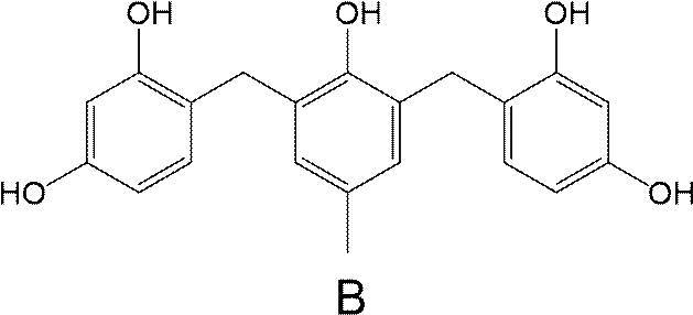
(実施例2)
コア粒子として「スミコランダムAA-5」(酸化アルミニウム、メジアン径:5.1μm、住友化学社製)を用い、表1に記載のシェル部の厚みとなるように蒸着条件を変更した以外は、実施例1と同様の手順に従って、無機粒子2を製造した。
次に、無機粒子1の代わりに無機粒子2を用いた以外は、実施例1と同様の手順に従って、硬化性組成物2を製造した。
コア粒子として「スミコランダムAA-5」(酸化アルミニウム、メジアン径:5.1μm、住友化学社製)を用い、表1に記載のシェル部の厚みとなるように蒸着条件を変更した以外は、実施例1と同様の手順に従って、無機粒子2を製造した。
次に、無機粒子1の代わりに無機粒子2を用いた以外は、実施例1と同様の手順に従って、硬化性組成物2を製造した。
(実施例3)
コア粒子として「ANF-A-05-F」(窒化アルミニウム、メジアン径:6.4μm、MARUWA社製)を用い、表1に記載のシェル部の厚みとなるように蒸着条件を変更した以外は、実施例1と同様の手順に従って、無機粒子3を製造した。
次に、無機粒子1の代わりに無機粒子3を用いた以外は、実施例1と同様の手順に従って、硬化性組成物3を製造した。
コア粒子として「ANF-A-05-F」(窒化アルミニウム、メジアン径:6.4μm、MARUWA社製)を用い、表1に記載のシェル部の厚みとなるように蒸着条件を変更した以外は、実施例1と同様の手順に従って、無機粒子3を製造した。
次に、無機粒子1の代わりに無機粒子3を用いた以外は、実施例1と同様の手順に従って、硬化性組成物3を製造した。
(実施例4)
コア粒子として「CP-2500」(銅、メジアン径:2.5μm、Aintech社製)を用い、表1に記載のシェル部の厚みとなるように蒸着条件を変更した以外は、実施例1と同様の手順に従って、無機粒子4を製造した。
次に、無機粒子1の代わりに無機粒子4を用いた以外は、実施例1と同様の手順に従って、硬化性組成物4を製造した。
コア粒子として「CP-2500」(銅、メジアン径:2.5μm、Aintech社製)を用い、表1に記載のシェル部の厚みとなるように蒸着条件を変更した以外は、実施例1と同様の手順に従って、無機粒子4を製造した。
次に、無機粒子1の代わりに無機粒子4を用いた以外は、実施例1と同様の手順に従って、硬化性組成物4を製造した。
(実施例5)
実施例1で製造された無機粒子1に対して、真空プラズマ処理を実施することで、無機粒子5を得た。
上記真空プラズマ処理は、無機粒子1(15g)に対し、ヤマト科学株式会社製の「プラズクリーナーPDC210」を用いて、真空プラズマ処理(ガス種:O2、圧力:30Pa、出力:500W)を行った。真空プラズマ処理を5分行うごとに処理対象の無機粒子を撹拌し、合計処理時間が45分になるまで真空プラズマ処理を行った。
次に、無機粒子1の代わりに無機粒子5を用いた以外は、実施例1と同様の手順に従って、硬化性組成物5を製造した。
実施例1で製造された無機粒子1に対して、真空プラズマ処理を実施することで、無機粒子5を得た。
上記真空プラズマ処理は、無機粒子1(15g)に対し、ヤマト科学株式会社製の「プラズクリーナーPDC210」を用いて、真空プラズマ処理(ガス種:O2、圧力:30Pa、出力:500W)を行った。真空プラズマ処理を5分行うごとに処理対象の無機粒子を撹拌し、合計処理時間が45分になるまで真空プラズマ処理を行った。
次に、無機粒子1の代わりに無機粒子5を用いた以外は、実施例1と同様の手順に従って、硬化性組成物5を製造した。
(実施例6~8)
無機粒子1の代わりに無機粒子2~4をそれぞれ用いた以外は、実施例5と同様の手順に従って、無機粒子6~8を製造した。
次に、無機粒子1の代わりに無機粒子6~8をそれぞれ用いた以外は、実施例1と同様の手順に従って、硬化性組成物6~8を製造した。
無機粒子1の代わりに無機粒子2~4をそれぞれ用いた以外は、実施例5と同様の手順に従って、無機粒子6~8を製造した。
次に、無機粒子1の代わりに無機粒子6~8をそれぞれ用いた以外は、実施例1と同様の手順に従って、硬化性組成物6~8を製造した。
(実施例9)
実施例5で製造された無機粒子5に対して、さらに金属カップリング剤による修飾処理を実施することで、無機粒子9を得た。
上記修飾処理は、無機粒子5をアセトニトリル(100ml)中で撹拌し、上記アセトニトリル中にさらに、シラン系カップリング剤「X12-984S」(信越化学工業社製)の加水分解調整液(1.25g)を添加した。上記アセトニトリルを室温で3時間撹拌して、修飾処理を行った。
処理後のアセトニトリル中の無機粒子をろ取した後、無機粒子をアセトニトリル(100ml)で洗浄し、40℃のオーブンで乾燥させることで、無機粒子9を得た。
なお、シラン系カップリング剤の加水分解調整液は、シラン系カップリング剤(1g)と、エタノール(500μl)、2-プロパノール(500μl)、水(720μl)、および、酢酸(100μl)を混合し、1時間撹拌することで調製した。
次に、無機粒子1の代わりに無機粒子9を用いた以外は、実施例1と同様の手順に従って、硬化性組成物9を製造した。
実施例5で製造された無機粒子5に対して、さらに金属カップリング剤による修飾処理を実施することで、無機粒子9を得た。
上記修飾処理は、無機粒子5をアセトニトリル(100ml)中で撹拌し、上記アセトニトリル中にさらに、シラン系カップリング剤「X12-984S」(信越化学工業社製)の加水分解調整液(1.25g)を添加した。上記アセトニトリルを室温で3時間撹拌して、修飾処理を行った。
処理後のアセトニトリル中の無機粒子をろ取した後、無機粒子をアセトニトリル(100ml)で洗浄し、40℃のオーブンで乾燥させることで、無機粒子9を得た。
なお、シラン系カップリング剤の加水分解調整液は、シラン系カップリング剤(1g)と、エタノール(500μl)、2-プロパノール(500μl)、水(720μl)、および、酢酸(100μl)を混合し、1時間撹拌することで調製した。
次に、無機粒子1の代わりに無機粒子9を用いた以外は、実施例1と同様の手順に従って、硬化性組成物9を製造した。
(実施例10)
無機粒子5の代わりに無機粒子6を用いた以外は、実施例9と同様の手順に従って、無機粒子10を製造した。
次に、無機粒子1の代わりに無機粒子10を用いた以外は、実施例1と同様の手順に従って、硬化性組成物10を製造した。
無機粒子5の代わりに無機粒子6を用いた以外は、実施例9と同様の手順に従って、無機粒子10を製造した。
次に、無機粒子1の代わりに無機粒子10を用いた以外は、実施例1と同様の手順に従って、硬化性組成物10を製造した。
(実施例11~12)
後述する表1に示すように、無機粒子10の含有量を調整した以外は、実施例10と同様の手順に従って、硬化性組成物11および12を製造した。
後述する表1に示すように、無機粒子10の含有量を調整した以外は、実施例10と同様の手順に従って、硬化性組成物11および12を製造した。
(実施例13)
コア粒子として「球状アルミナ粉末」(酸化アルミニウム、メジアン径:122μm、エアブラウン製)を用い、表1に記載のシェル部の厚みとなるように蒸着条件を変更した以外は、実施例1と同様の手順に従って、無機粒子13A-1を製造した。
無機粒子1の代わりに無機粒子13A-1を用いた以外は、実施例5と同様の手順に従って、無機粒子13A-2を製造した。
無機粒子5の代わりに無機粒子13A-2を用いた以外は、実施例9と同様の手順に従って、無機粒子13A-3を製造した。
コア粒子として「高純度アルミナビーズTB」(酸化アルミニウム、メジアン径:250μm、大明化学工業社製)を用い、表1に記載のシェル部の厚みとなるように蒸着条件を変更した以外は、実施例1と同様の手順に従って、無機粒子13B-1を製造した。
無機粒子1の代わりに無機粒子13B-1を用いた以外は、実施例5と同様の手順に従って、無機粒子13B-2を製造した。
無機粒子5の代わりに無機粒子13B-2を用いた以外は、実施例9と同様の手順に従って、無機粒子13B-3を製造した。
次に、無機粒子1の代わりに無機粒子10、無機粒子13A-3および無機粒子13B-3を用い、後述する表1に示すように、これらの無機粒子の含有量を調整した以外は、実施例1と同様の手順に従って、硬化性組成物13を製造した。
コア粒子として「球状アルミナ粉末」(酸化アルミニウム、メジアン径:122μm、エアブラウン製)を用い、表1に記載のシェル部の厚みとなるように蒸着条件を変更した以外は、実施例1と同様の手順に従って、無機粒子13A-1を製造した。
無機粒子1の代わりに無機粒子13A-1を用いた以外は、実施例5と同様の手順に従って、無機粒子13A-2を製造した。
無機粒子5の代わりに無機粒子13A-2を用いた以外は、実施例9と同様の手順に従って、無機粒子13A-3を製造した。
コア粒子として「高純度アルミナビーズTB」(酸化アルミニウム、メジアン径:250μm、大明化学工業社製)を用い、表1に記載のシェル部の厚みとなるように蒸着条件を変更した以外は、実施例1と同様の手順に従って、無機粒子13B-1を製造した。
無機粒子1の代わりに無機粒子13B-1を用いた以外は、実施例5と同様の手順に従って、無機粒子13B-2を製造した。
無機粒子5の代わりに無機粒子13B-2を用いた以外は、実施例9と同様の手順に従って、無機粒子13B-3を製造した。
次に、無機粒子1の代わりに無機粒子10、無機粒子13A-3および無機粒子13B-3を用い、後述する表1に示すように、これらの無機粒子の含有量を調整した以外は、実施例1と同様の手順に従って、硬化性組成物13を製造した。
(実施例14)
無機粒子5の代わりに無機粒子7を用いた以外は、実施例9と同様の手順に従って、無機粒子14を製造した。
次に、無機粒子1の代わりに無機粒子14を用いた以外は、実施例1と同様の手順に従って、硬化性組成物10を製造した。
無機粒子5の代わりに無機粒子7を用いた以外は、実施例9と同様の手順に従って、無機粒子14を製造した。
次に、無機粒子1の代わりに無機粒子14を用いた以外は、実施例1と同様の手順に従って、硬化性組成物10を製造した。
(実施例15)
無機粒子5の代わりに無機粒子8を用いた以外は、実施例9と同様の手順に従って、無機粒子15を製造した。
次に、無機粒子1の代わりに無機粒子15を用いた以外は、実施例1と同様の手順に従って、硬化性組成物10を製造した。
無機粒子5の代わりに無機粒子8を用いた以外は、実施例9と同様の手順に従って、無機粒子15を製造した。
次に、無機粒子1の代わりに無機粒子15を用いた以外は、実施例1と同様の手順に従って、硬化性組成物10を製造した。
(比較例1)
無機粒子1の代わりに「サンスフィアNP-30」(二酸化ケイ素、メジアン径:4.3μm、AGC社製)を用いた以外は、実施例1と同様の手順に従って、硬化性組成物C1を製造した。
無機粒子1の代わりに「サンスフィアNP-30」(二酸化ケイ素、メジアン径:4.3μm、AGC社製)を用いた以外は、実施例1と同様の手順に従って、硬化性組成物C1を製造した。
(比較例2)
無機粒子1の代わりに「スミコランダムAA-5」(酸化アルミニウム、メジアン径:5.1μm、住友化学社製)を用いた以外は、実施例1と同様の手順に従って、硬化性組成物C2を製造した。
無機粒子1の代わりに「スミコランダムAA-5」(酸化アルミニウム、メジアン径:5.1μm、住友化学社製)を用いた以外は、実施例1と同様の手順に従って、硬化性組成物C2を製造した。
(比較例3)
無機粒子1の代わりに「デンカボロンナイトライドSP-2」(窒化ホウ素、メジアン径:4.0μm、デンカ社製)を用いた以外は、実施例1と同様の手順に従って、硬化性組成物C3を製造した。
無機粒子1の代わりに「デンカボロンナイトライドSP-2」(窒化ホウ素、メジアン径:4.0μm、デンカ社製)を用いた以外は、実施例1と同様の手順に従って、硬化性組成物C3を製造した。
(比較例4)
無機粒子1の代わりに「サンスフィアNP-30」と上記「デンカボロンナイトライドSP-2」とを表1に示す含有量にて用いた以外は、実施例1と同様の手順に従って、硬化性組成物C4を製造した。
無機粒子1の代わりに「サンスフィアNP-30」と上記「デンカボロンナイトライドSP-2」とを表1に示す含有量にて用いた以外は、実施例1と同様の手順に従って、硬化性組成物C4を製造した。
<評価>
実施例および比較例で製造した無機粒子および硬化性組成物における、各項目の評価方法、および、評価基準を以下に示す。
実施例および比較例で製造した無機粒子および硬化性組成物における、各項目の評価方法、および、評価基準を以下に示す。
(無機粒子のメジアン径)
無機粒子のメジアン径は、マルバーン社製「Mastersizer 3000」を用いて測定した。
無機粒子のメジアン径は、マルバーン社製「Mastersizer 3000」を用いて測定した。
(シェル部厚み)
シェル部厚みは、マルバーン社製「Mastersizer 3000」を用い、コア粒子のメジアン径を、シェル部を形成した後の無機粒子のメジアン径から差し引き、得られた値を2で除することで算出した。
シェル部厚みは、マルバーン社製「Mastersizer 3000」を用い、コア粒子のメジアン径を、シェル部を形成した後の無機粒子のメジアン径から差し引き、得られた値を2で除することで算出した。
(無機粒子のアスペクト比)
上述した方法により、各実施例および比較例にて使用した無機粒子のアスペクト比を算出した。
上述した方法により、各実施例および比較例にて使用した無機粒子のアスペクト比を算出した。
(ホウ素原子に対する酸素原子の原子比率)
無機粒子表面における酸素原子濃度およびホウ素原子濃度(ともに単位は原子%)を、X線光電子分光装置(Ulvac-PHI社製:Versa Probe II)を用いて、明細書中にて上述した条件でそれぞれ測定した。
得られた結果から、無機粒子表面における、ホウ素原子に対する酸素原子の原子比(酸素原子/ホウ素原子)を計算した。
なお、実施例9~15に用いた無機粒子の原子比は、金属カップリング剤による処理の前に測定した。
無機粒子表面における酸素原子濃度およびホウ素原子濃度(ともに単位は原子%)を、X線光電子分光装置(Ulvac-PHI社製:Versa Probe II)を用いて、明細書中にて上述した条件でそれぞれ測定した。
得られた結果から、無機粒子表面における、ホウ素原子に対する酸素原子の原子比(酸素原子/ホウ素原子)を計算した。
なお、実施例9~15に用いた無機粒子の原子比は、金属カップリング剤による処理の前に測定した。
(D値)
無機粒子のX線回折測定を行い、下記式(1)によりD値を求めた。
式(1): D=B(OH)3(002)/BN(002)
B(OH)3(002):X線回折により測定される三斜晶系の空間群を有する水酸化ホウ素の(002)面に由来するピーク強度(2θ=25°~30°)
BN(002):X線回折により測定される六方晶系の空間群を有する窒化ホウ素の(002)面に由来するピーク強度(2θ=27.5°~28.5°)
X線回折測定には、XRD7000(島津製作所製)を用いた。無機粒子のX線回折測定は、粉末測定用のガラス製ホルダに無機粒子を充填して行った。
なお、B(OH)3(002)、および、BN(002)は、コア粒子のみのX線回折チャートを取得した後、無機粒子のX線回折チャートを取得し、無機粒子のX線回折チャートから、コア粒子のみのX線回折チャートを差し引くことで求めた。
なお、実施例9~15に用いた無機粒子のD値は、金属カップリング剤による処理の前に測定した。
無機粒子のX線回折測定を行い、下記式(1)によりD値を求めた。
式(1): D=B(OH)3(002)/BN(002)
B(OH)3(002):X線回折により測定される三斜晶系の空間群を有する水酸化ホウ素の(002)面に由来するピーク強度(2θ=25°~30°)
BN(002):X線回折により測定される六方晶系の空間群を有する窒化ホウ素の(002)面に由来するピーク強度(2θ=27.5°~28.5°)
X線回折測定には、XRD7000(島津製作所製)を用いた。無機粒子のX線回折測定は、粉末測定用のガラス製ホルダに無機粒子を充填して行った。
なお、B(OH)3(002)、および、BN(002)は、コア粒子のみのX線回折チャートを取得した後、無機粒子のX線回折チャートを取得し、無機粒子のX線回折チャートから、コア粒子のみのX線回折チャートを差し引くことで求めた。
なお、実施例9~15に用いた無機粒子のD値は、金属カップリング剤による処理の前に測定した。
(シェル部の鉄原子含有量)
上述した方法により無機粒子のシェル部の鉄原子含有量を算出し、以下の基準に従って評価した。
上述した方法により無機粒子のシェル部の鉄原子含有量を算出し、以下の基準に従って評価した。
-鉄原子含有量の評価基準-
1:100質量ppm超
2:10質量ppm超100質量ppm以下
3:5質量ppm超10質量ppm以下
4:5質量ppm以下
1:100質量ppm超
2:10質量ppm超100質量ppm以下
3:5質量ppm超10質量ppm以下
4:5質量ppm以下
(熱伝導性)
アプリケーターを用いて、離型処理したペットフィルム(PET756501、リンテック社製、膜厚75μm)の離型面上に、調製した各実施例または比較例の硬化性組成物を均一に塗布し、120℃で5分間放置して塗膜を得た。
このような塗膜付きペットフィルムを2枚作製し、2枚の塗膜付きペットフィルム同士を塗膜面同士で貼り合せてから、空気下で熱プレス(熱板温度120℃、圧力20MPaで1分間処理)することで半硬化膜を得た。得られた半硬化膜を空気下で熱プレス(熱板温度180℃、圧力20MPaで10分間処理した後、さらに、常圧下で180℃90分)で処理して塗膜を硬化し、樹脂シートを得た。樹脂シートの両面にあるペットフィルムを剥がし、平均膜厚200μmの熱伝導シートを得た。
アプリケーターを用いて、離型処理したペットフィルム(PET756501、リンテック社製、膜厚75μm)の離型面上に、調製した各実施例または比較例の硬化性組成物を均一に塗布し、120℃で5分間放置して塗膜を得た。
このような塗膜付きペットフィルムを2枚作製し、2枚の塗膜付きペットフィルム同士を塗膜面同士で貼り合せてから、空気下で熱プレス(熱板温度120℃、圧力20MPaで1分間処理)することで半硬化膜を得た。得られた半硬化膜を空気下で熱プレス(熱板温度180℃、圧力20MPaで10分間処理した後、さらに、常圧下で180℃90分)で処理して塗膜を硬化し、樹脂シートを得た。樹脂シートの両面にあるペットフィルムを剥がし、平均膜厚200μmの熱伝導シートを得た。
各組成物を用いて得られた、それぞれの熱伝導シートを用いて、熱伝導性評価を実施した。下記の方法で熱伝導率の測定を行い、下記の基準にしたがって熱伝導性を評価した。
なお、実用上、2~4の評価が好ましい。
なお、実用上、2~4の評価が好ましい。
-熱伝導率(W/m・k)の測定-
(1)NETZSCH社製の「LFA467」を用いて、レーザーフラッシュ法で熱伝導シートの厚み方向の熱拡散率を測定した。
(2)メトラー・トレド社製の天秤「XS204」を用いて、熱伝導シートの比重をアルキメデス法(「固体比重測定キット」使用)で測定した。
(3)セイコーインスツル社製の「DSC320/6200」を用い、10℃/分の昇温条件の下、25℃における熱伝導シートの比熱を求めた。
(4)得られた熱拡散率に比重および比熱を乗じて、熱伝導シートの熱伝導率を算出した。
(1)NETZSCH社製の「LFA467」を用いて、レーザーフラッシュ法で熱伝導シートの厚み方向の熱拡散率を測定した。
(2)メトラー・トレド社製の天秤「XS204」を用いて、熱伝導シートの比重をアルキメデス法(「固体比重測定キット」使用)で測定した。
(3)セイコーインスツル社製の「DSC320/6200」を用い、10℃/分の昇温条件の下、25℃における熱伝導シートの比熱を求めた。
(4)得られた熱拡散率に比重および比熱を乗じて、熱伝導シートの熱伝導率を算出した。
-熱伝導性の評価基準-
1:1.0W/(K・cm)未満
2:1.0W/(K・cm)以上3.0W/(K・cm)未満
3:3.0W/(K・cm)以上5.0W/(K・cm)未満
4:5.0W/(K・cm)以上
1:1.0W/(K・cm)未満
2:1.0W/(K・cm)以上3.0W/(K・cm)未満
3:3.0W/(K・cm)以上5.0W/(K・cm)未満
4:5.0W/(K・cm)以上
(流動性)
アプリケーターを用いて、離型処理したペットフィルム(PET756501、リンテック社製、膜厚75μm)の離型面上に、調製した各実施例または比較例の硬化性組成物を均一に塗布し、120℃で5分間放置して塗膜(厚み:200μm)を得た。
得られた塗膜からペットフィルムを剥離し、5cm角の塗膜の試験片を切り出した。この試験片を、上記ペットフィルムの離型面で挟持し、空気下で熱プレス(熱板温度175℃、圧力6MPaで5分間)を行った。
プレス前後における試験片の大きさの比較から、プレスにおける試験片の上下左右の延伸長さを計測し、上下左右の延伸長さを平均して流動性の評価を行った。延伸長さは、プレス前の試験片の各辺から各辺が伸びる方向とは直交する方向での最大長さを計測した。
流動性の評価基準を以下に示す。なお、実用上、3~5の評価が好ましい。
アプリケーターを用いて、離型処理したペットフィルム(PET756501、リンテック社製、膜厚75μm)の離型面上に、調製した各実施例または比較例の硬化性組成物を均一に塗布し、120℃で5分間放置して塗膜(厚み:200μm)を得た。
得られた塗膜からペットフィルムを剥離し、5cm角の塗膜の試験片を切り出した。この試験片を、上記ペットフィルムの離型面で挟持し、空気下で熱プレス(熱板温度175℃、圧力6MPaで5分間)を行った。
プレス前後における試験片の大きさの比較から、プレスにおける試験片の上下左右の延伸長さを計測し、上下左右の延伸長さを平均して流動性の評価を行った。延伸長さは、プレス前の試験片の各辺から各辺が伸びる方向とは直交する方向での最大長さを計測した。
流動性の評価基準を以下に示す。なお、実用上、3~5の評価が好ましい。
-流動性の評価基準-
1:0.5cm未満
2:0.5cm以上1.0cm未満
3:1.0cm以上1.5cm未満
4:1.5cm以上2.0cm未満
5:2.0cm以上
1:0.5cm未満
2:0.5cm以上1.0cm未満
3:1.0cm以上1.5cm未満
4:1.5cm以上2.0cm未満
5:2.0cm以上
(絶縁信頼性)
熱伝導性評価と同様の方法で半硬化膜を得た。
半硬化膜をペットフィルムから剥離し、これを直径2.0cmの銅製の電極で挟持し、空気下で熱プレス(熱板温度180℃、圧力20MPaで10分間処理した後、さらに、常圧下で180℃90分)で処理して塗膜を硬化し、試験体を得た。
試験体の各電極に直流電源装置(AEM、エスペック社製)の電極を接続し、恒温恒湿試験機(PL、エスペック社製)内に設置した。恒温恒湿試験機内は、温度85℃、湿度85%に保持し、試験体の電極間には1.5kVの直流電圧を印加し続けた。
電圧の印加は抵抗値が1.0×10⁷Ω以下となるまで実施し、抵抗値が1.0×10⁷Ω以下になった時間を記録した。この時間をリーク時間とし、絶縁信頼性の評価に用いた。
絶縁信頼性の評価基準を以下に示す。なお、実用上、3の評価が好ましい。
熱伝導性評価と同様の方法で半硬化膜を得た。
半硬化膜をペットフィルムから剥離し、これを直径2.0cmの銅製の電極で挟持し、空気下で熱プレス(熱板温度180℃、圧力20MPaで10分間処理した後、さらに、常圧下で180℃90分)で処理して塗膜を硬化し、試験体を得た。
試験体の各電極に直流電源装置(AEM、エスペック社製)の電極を接続し、恒温恒湿試験機(PL、エスペック社製)内に設置した。恒温恒湿試験機内は、温度85℃、湿度85%に保持し、試験体の電極間には1.5kVの直流電圧を印加し続けた。
電圧の印加は抵抗値が1.0×10⁷Ω以下となるまで実施し、抵抗値が1.0×10⁷Ω以下になった時間を記録した。この時間をリーク時間とし、絶縁信頼性の評価に用いた。
絶縁信頼性の評価基準を以下に示す。なお、実用上、3の評価が好ましい。
-絶縁信頼性の評価基準-
1:50時間未満
2:50時間以上100時間未満
3:100時間以上
1:50時間未満
2:50時間以上100時間未満
3:100時間以上
表中、「種類」欄は、無機粒子の種類を表す。例えば、実施例1の「種類」欄の「1」は、上述した無機粒子1を用いたことを表す。
表中、「コア材」欄は、コア部に含まれる材料を表す。「シリカ」は二酸化ケイ素、「アルミナ」は酸化アルミニウム、「BN」は窒化ホウ素、「AlN」は窒化アルミニウム、および、「銅」は銅を表す。
表中、「コア径」欄はコア粒子のメジアン径を表す。
表中、「シェル厚」欄は、シェル部の厚みを表す。
表中、「無機粒子径」欄は、無機粒子のメジアン径を表す。
表中、「長径/短径」欄は、無機粒子のアスペクト比を表す。
表中、「鉄原子含有量」欄は、シェル部全質量に対する鉄原子の含有量(質量ppm)を表す。
表中、「真空プラズマ処理」欄は、無機粒子を製造する際に真空プラズマ処理を実施した場合を「A」、実施しなかった場合を「B」とする。
表中、「金属カップリング剤」欄は、無機粒子を製造する際に金属カップリング剤により処理を実施した場合を「A」、実施しなかった場合を「B」とする。
表中、「表面O/B」欄は、X線光電子分光分析によって求められる、無機粒子の表面におけるホウ素原子に対する酸素原子の原子比率を表す。
表中、「D値」欄は、式(1)で求められるD値を表す。
表中、「無機粒子(体積%)」欄は、硬化性組成物の全固形分に対する無機粒子の含有量(体積%)を表す。
表中、「硬化物(体積%)」欄は、硬化性組成物の全固形分に対する無機粒子以外の他の固形分の含有量(体積%)を表す。
表中、「コア材」欄は、コア部に含まれる材料を表す。「シリカ」は二酸化ケイ素、「アルミナ」は酸化アルミニウム、「BN」は窒化ホウ素、「AlN」は窒化アルミニウム、および、「銅」は銅を表す。
表中、「コア径」欄はコア粒子のメジアン径を表す。
表中、「シェル厚」欄は、シェル部の厚みを表す。
表中、「無機粒子径」欄は、無機粒子のメジアン径を表す。
表中、「長径/短径」欄は、無機粒子のアスペクト比を表す。
表中、「鉄原子含有量」欄は、シェル部全質量に対する鉄原子の含有量(質量ppm)を表す。
表中、「真空プラズマ処理」欄は、無機粒子を製造する際に真空プラズマ処理を実施した場合を「A」、実施しなかった場合を「B」とする。
表中、「金属カップリング剤」欄は、無機粒子を製造する際に金属カップリング剤により処理を実施した場合を「A」、実施しなかった場合を「B」とする。
表中、「表面O/B」欄は、X線光電子分光分析によって求められる、無機粒子の表面におけるホウ素原子に対する酸素原子の原子比率を表す。
表中、「D値」欄は、式(1)で求められるD値を表す。
表中、「無機粒子(体積%)」欄は、硬化性組成物の全固形分に対する無機粒子の含有量(体積%)を表す。
表中、「硬化物(体積%)」欄は、硬化性組成物の全固形分に対する無機粒子以外の他の固形分の含有量(体積%)を表す。
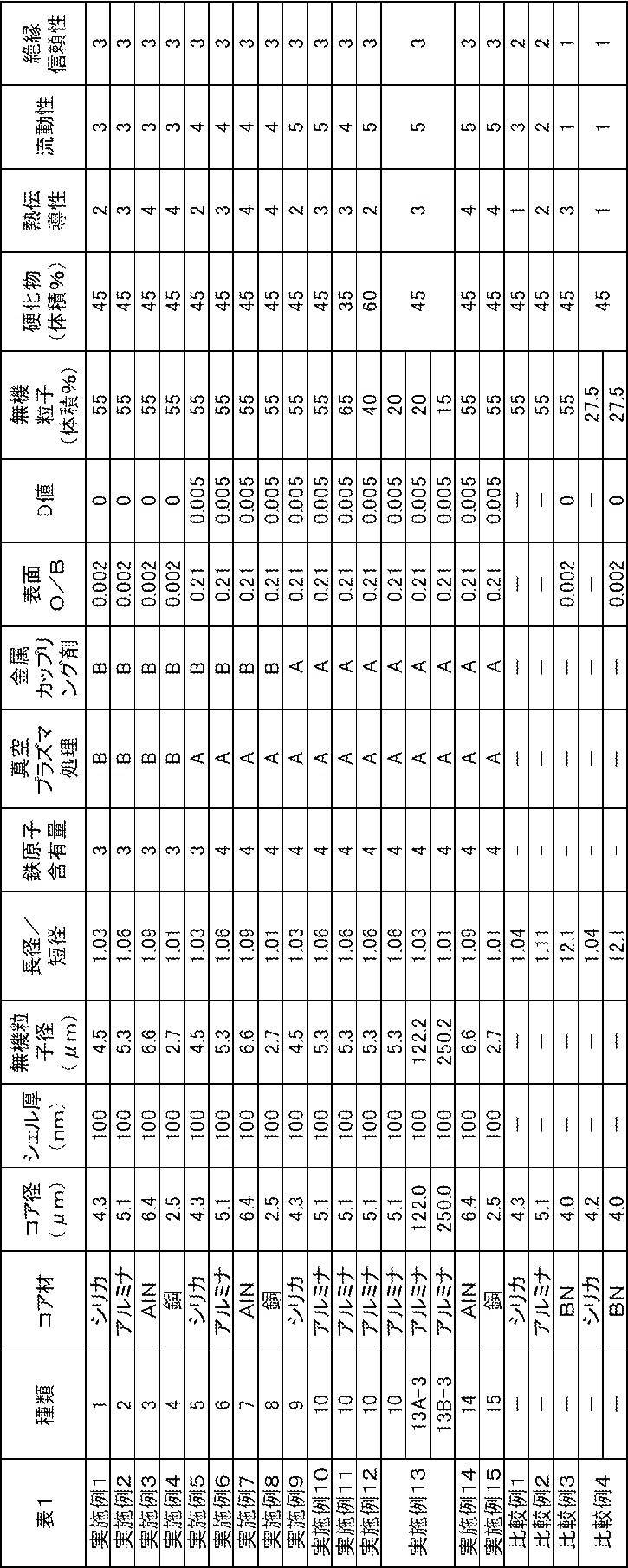
表1の結果より、本発明の無機粒子は所望の効果を示すことが確認された。
実施例5~15と、実施例1~4との比較から、無機粒子が、上記要件1および要件2を満たす場合、本発明の効果がより優れることが確認された。
実施例9~15と、実施例1~8との比較から、無機粒子の表面が、金属カップリング剤で修飾されると、本発明の効果がより優れることが確認された。
実施例10と、実施例11および12との比較から、組成物の全固形分に対する無機粒子の含有量が、45体積%~60体積%である場合、本発明の効果がより優れることが確認された。
実施例5~15と、実施例1~4との比較から、無機粒子が、上記要件1および要件2を満たす場合、本発明の効果がより優れることが確認された。
実施例9~15と、実施例1~8との比較から、無機粒子の表面が、金属カップリング剤で修飾されると、本発明の効果がより優れることが確認された。
実施例10と、実施例11および12との比較から、組成物の全固形分に対する無機粒子の含有量が、45体積%~60体積%である場合、本発明の効果がより優れることが確認された。
Claims (16)
- コア部と、シェル部とを有し、球状である無機粒子であって、
前記コア部が、二酸化ケイ素、酸化アルミニウム、窒化アルミニウム、および、銅からなる群より選択される少なくとも1種を含み、
前記シェル部が、窒化ホウ素を含み、
前記シェル部に含まれる鉄原子の含有量が、前記シェル部の全質量に対して、10質量ppm以下である、無機粒子。 - 前記シェル部の厚みが、20nm~1μmである、請求項1に記載の無機粒子。
- 要件1および要件2を満たす、請求項1または2に記載の無機粒子。
要件1:X線光電子分光分析によって求められる、前記無機粒子の表面におけるホウ素原子に対する酸素原子の原子比率が0.12以上である。
要件2:式(1)で求められるD値が0.010以下である。
式(1): D=B(OH)3(002)/BN(002)
B(OH)3(002):X線回折により測定される三斜晶系の空間群を有する水酸化ホウ素の(002)に由来するピーク強度
BN(002):X線回折により測定される六方晶系の空間群を有する窒化ホウ素の(002)に由来するピーク強度 - 前記D値が0.005以下である、請求項3に記載の無機粒子。
- 前記原子比率が0.15以上である、請求項3または4に記載の無機粒子。
- 前記原子比率が0.25以下である、請求項3~5のいずれか1項に記載の無機粒子。
- メジアン径が、300μm以下である、請求項1~6のいずれか1項に記載の無機粒子。
- メジアン径が、100μm以下である、請求項1~7のいずれか1項に記載の無機粒子。
- 体積基準の頻度分布を表す粒度分布曲線において、1.0~50μmの範囲、100~150μmの範囲、および、200~300μmの範囲にそれぞれピークを有する、請求項1~8のいずれか1項に記載の無機粒子。
- 表面が金属カップリング剤で修飾された、請求項1~9のいずれか1項に記載の無機粒子。
- 請求項1~10のいずれか1項に記載の無機粒子の製造方法であって、
前記シェル部を、蒸着法またはスパッタ法により形成する工程を有する、無機粒子の製造方法。 - 請求項1~10のいずれか1項に記載の無機粒子と、樹脂またはその前駆体とを含む、組成物。
- 前記樹脂またはその前駆体が、熱硬化性化合物である、請求項12に記載の組成物。
- 前記無機粒子の含有量が、前記組成物の全固形分に対して、45~60体積%である、請求項12または13に記載の組成物。
- シート状である、請求項12~14のいずれか1項に記載の組成物。
- 請求項15に記載の組成物を用いて、コンプレッションモールド法で半導体部材を封止する工程を有する、電子デバイスの製造方法。
Priority Applications (1)
| Application Number | Priority Date | Filing Date | Title |
|---|---|---|---|
| JP2023510850A JP7766081B2 (ja) | 2021-03-31 | 2022-03-11 | 無機粒子、無機粒子の製造方法、組成物、および、電子デバイスの製造方法 |
Applications Claiming Priority (2)
| Application Number | Priority Date | Filing Date | Title |
|---|---|---|---|
| JP2021060319 | 2021-03-31 | ||
| JP2021-060319 | 2021-03-31 |
Publications (1)
| Publication Number | Publication Date |
|---|---|
| WO2022209784A1 true WO2022209784A1 (ja) | 2022-10-06 |
Family
ID=83456252
Family Applications (1)
| Application Number | Title | Priority Date | Filing Date |
|---|---|---|---|
| PCT/JP2022/011049 Ceased WO2022209784A1 (ja) | 2021-03-31 | 2022-03-11 | 無機粒子、無機粒子の製造方法、組成物、および、電子デバイスの製造方法 |
Country Status (3)
| Country | Link |
|---|---|
| JP (1) | JP7766081B2 (ja) |
| TW (1) | TW202239848A (ja) |
| WO (1) | WO2022209784A1 (ja) |
Citations (4)
| Publication number | Priority date | Publication date | Assignee | Title |
|---|---|---|---|---|
| JP2016192474A (ja) * | 2015-03-31 | 2016-11-10 | 住友ベークライト株式会社 | 造粒粉、放熱用樹脂組成物、放熱シート、放熱部材、および半導体装置 |
| WO2019189794A1 (ja) * | 2018-03-30 | 2019-10-03 | 日本発條株式会社 | 熱伝導性複合粒子及びその製造方法、絶縁樹脂組成物、絶縁樹脂成形体、回路基板用積層板、金属ベース回路基板、並びに、パワーモジュール |
| CN110694559A (zh) * | 2018-07-10 | 2020-01-17 | 中国科学院金属研究所 | 一种二维材料纳米片包覆微球的制备方法与应用 |
| CN112409757A (zh) * | 2020-10-21 | 2021-02-26 | 江苏科化新材料科技有限公司 | 一种高功率模块封装用高导热环氧塑封料及其制备方法 |
Family Cites Families (1)
| Publication number | Priority date | Publication date | Assignee | Title |
|---|---|---|---|---|
| CN112063020B (zh) | 2020-09-04 | 2021-09-07 | 四川大学 | 一种核壳球状导热填料及其制备方法和应用 |
-
2022
- 2022-03-11 JP JP2023510850A patent/JP7766081B2/ja active Active
- 2022-03-11 WO PCT/JP2022/011049 patent/WO2022209784A1/ja not_active Ceased
- 2022-03-21 TW TW111110237A patent/TW202239848A/zh unknown
Patent Citations (4)
| Publication number | Priority date | Publication date | Assignee | Title |
|---|---|---|---|---|
| JP2016192474A (ja) * | 2015-03-31 | 2016-11-10 | 住友ベークライト株式会社 | 造粒粉、放熱用樹脂組成物、放熱シート、放熱部材、および半導体装置 |
| WO2019189794A1 (ja) * | 2018-03-30 | 2019-10-03 | 日本発條株式会社 | 熱伝導性複合粒子及びその製造方法、絶縁樹脂組成物、絶縁樹脂成形体、回路基板用積層板、金属ベース回路基板、並びに、パワーモジュール |
| CN110694559A (zh) * | 2018-07-10 | 2020-01-17 | 中国科学院金属研究所 | 一种二维材料纳米片包覆微球的制备方法与应用 |
| CN112409757A (zh) * | 2020-10-21 | 2021-02-26 | 江苏科化新材料科技有限公司 | 一种高功率模块封装用高导热环氧塑封料及其制备方法 |
Non-Patent Citations (1)
| Title |
|---|
| WEISZMANTEL, E. PFEIFER, T. RICHTER, F.: "Electron microscopic analysis of cubic boron nitride films deposited on fused silica", THIN SOLID FILMS, vol. 408, no. 1-2, 3 April 2002 (2002-04-03), AMSTERDAM, NL , pages 1 - 5, XP004351334, ISSN: 0040-6090, DOI: 10.1016/S0040-6090(02)00092-5 * |
Also Published As
| Publication number | Publication date |
|---|---|
| JP7766081B2 (ja) | 2025-11-07 |
| TW202239848A (zh) | 2022-10-16 |
| JPWO2022209784A1 (ja) | 2022-10-06 |
Similar Documents
| Publication | Publication Date | Title |
|---|---|---|
| JP6687818B1 (ja) | 珪素含有酸化物被覆窒化アルミニウム粒子の製造方法および珪素含有酸化物被覆窒化アルミニウム粒子 | |
| JP7582190B2 (ja) | シリカ被覆窒化ホウ素粒子の製造方法、シリカ被覆窒化ホウ素粒子 | |
| TWI745158B (zh) | 含矽氧化物被覆氮化鋁粒子的製造方法及放熱性樹脂組成物的製造方法 | |
| TWI751632B (zh) | 無機粒子分散樹脂組成物及無機粒子分散樹脂組成物的製造方法 | |
| CN108473308A (zh) | 六方晶氮化硼粉末、其制造方法、树脂组合物及树脂片 | |
| US12305113B2 (en) | Heat-conductive resin composition and heat dissipation sheet | |
| JP7580273B2 (ja) | 窒化ホウ素粉末、熱伝導性樹脂組成物、放熱シート及び電子部品構造体 | |
| JP7291304B2 (ja) | 窒化ホウ素粉末、放熱シート及び放熱シートの製造方法 | |
| JP7524889B2 (ja) | 珪素含有酸化物被覆窒化アルミニウム粒子の製造方法及び樹脂組成物の製造方法 | |
| JP7766081B2 (ja) | 無機粒子、無機粒子の製造方法、組成物、および、電子デバイスの製造方法 | |
| WO2022149553A1 (ja) | 凝集窒化ホウ素粒子、窒化ホウ素粉末、熱伝導性樹脂組成物及び放熱シート | |
| JP7468803B1 (ja) | 珪素含有酸化物被覆窒化アルミニウム粒子の製造方法 | |
| JP7694847B2 (ja) | 珪素含有酸化物被覆窒化アルミニウム粒子の製造方法、及び珪素含有酸化物被覆窒化アルミニウム粒子 | |
| JP7806978B2 (ja) | 窒化アルミニウムフィラー、窒化アルミニウムフィラーの製造方法、樹脂組成物、及び樹脂組成物の製造方法 | |
| WO2024127697A1 (ja) | 珪素含有酸化物被覆窒化アルミニウム粒子の製造方法 | |
| JP7124249B1 (ja) | 放熱シート及び放熱シートの製造方法 | |
| JP2020073625A (ja) | シリカ被覆窒化アルミニウム粒子分散樹脂組成物の製造方法、その硬化物からなるシートの製造方法、およびシートを備えるパワーデバイスの製造方法 |
Legal Events
| Date | Code | Title | Description |
|---|---|---|---|
| 121 | Ep: the epo has been informed by wipo that ep was designated in this application |
Ref document number: 22780005 Country of ref document: EP Kind code of ref document: A1 |
|
| WWE | Wipo information: entry into national phase |
Ref document number: 2023510850 Country of ref document: JP |
|
| NENP | Non-entry into the national phase |
Ref country code: DE |
|
| 122 | Ep: pct application non-entry in european phase |
Ref document number: 22780005 Country of ref document: EP Kind code of ref document: A1 |