WO2022209356A1 - スパッタリング装置 - Google Patents
スパッタリング装置 Download PDFInfo
- Publication number
- WO2022209356A1 WO2022209356A1 PCT/JP2022/005657 JP2022005657W WO2022209356A1 WO 2022209356 A1 WO2022209356 A1 WO 2022209356A1 JP 2022005657 W JP2022005657 W JP 2022005657W WO 2022209356 A1 WO2022209356 A1 WO 2022209356A1
- Authority
- WO
- WIPO (PCT)
- Prior art keywords
- shutter
- reflector
- retracted
- exhaust pump
- reflectors
- Prior art date
Links
- 238000004544 sputter deposition Methods 0.000 title claims abstract description 71
- 230000015572 biosynthetic process Effects 0.000 claims abstract description 14
- 238000010438 heat treatment Methods 0.000 claims description 59
- 230000005855 radiation Effects 0.000 claims description 59
- 239000010409 thin film Substances 0.000 claims description 22
- 239000010408 film Substances 0.000 claims description 18
- 239000002245 particle Substances 0.000 claims description 11
- 238000001816 cooling Methods 0.000 claims description 10
- 239000007789 gas Substances 0.000 description 54
- 238000004140 cleaning Methods 0.000 description 9
- 230000005856 abnormality Effects 0.000 description 8
- 230000007547 defect Effects 0.000 description 8
- 239000000758 substrate Substances 0.000 description 8
- 238000010586 diagram Methods 0.000 description 6
- 239000000463 material Substances 0.000 description 5
- 230000004048 modification Effects 0.000 description 4
- 238000012986 modification Methods 0.000 description 4
- XKRFYHLGVUSROY-UHFFFAOYSA-N Argon Chemical compound [Ar] XKRFYHLGVUSROY-UHFFFAOYSA-N 0.000 description 3
- 230000005540 biological transmission Effects 0.000 description 3
- 239000002826 coolant Substances 0.000 description 3
- 230000003247 decreasing effect Effects 0.000 description 3
- 229910001220 stainless steel Inorganic materials 0.000 description 3
- 239000010935 stainless steel Substances 0.000 description 3
- 108010083687 Ion Pumps Proteins 0.000 description 2
- 229910052786 argon Inorganic materials 0.000 description 2
- 230000006866 deterioration Effects 0.000 description 2
- 230000000694 effects Effects 0.000 description 2
- 230000004907 flux Effects 0.000 description 2
- 229910052751 metal Inorganic materials 0.000 description 2
- 239000002184 metal Substances 0.000 description 2
- 230000006641 stabilisation Effects 0.000 description 2
- 238000011105 stabilization Methods 0.000 description 2
- 230000008646 thermal stress Effects 0.000 description 2
- RYGMFSIKBFXOCR-UHFFFAOYSA-N Copper Chemical compound [Cu] RYGMFSIKBFXOCR-UHFFFAOYSA-N 0.000 description 1
- XUIMIQQOPSSXEZ-UHFFFAOYSA-N Silicon Chemical compound [Si] XUIMIQQOPSSXEZ-UHFFFAOYSA-N 0.000 description 1
- 238000010521 absorption reaction Methods 0.000 description 1
- 229910052782 aluminium Inorganic materials 0.000 description 1
- XAGFODPZIPBFFR-UHFFFAOYSA-N aluminium Chemical compound [Al] XAGFODPZIPBFFR-UHFFFAOYSA-N 0.000 description 1
- -1 argon ions Chemical class 0.000 description 1
- QVGXLLKOCUKJST-UHFFFAOYSA-N atomic oxygen Chemical compound [O] QVGXLLKOCUKJST-UHFFFAOYSA-N 0.000 description 1
- 238000007664 blowing Methods 0.000 description 1
- 229910052802 copper Inorganic materials 0.000 description 1
- 239000010949 copper Substances 0.000 description 1
- 230000003111 delayed effect Effects 0.000 description 1
- 238000000151 deposition Methods 0.000 description 1
- 239000012535 impurity Substances 0.000 description 1
- 238000009434 installation Methods 0.000 description 1
- 230000009191 jumping Effects 0.000 description 1
- 238000001755 magnetron sputter deposition Methods 0.000 description 1
- 230000007257 malfunction Effects 0.000 description 1
- 239000001301 oxygen Substances 0.000 description 1
- 229910052760 oxygen Inorganic materials 0.000 description 1
- 238000005498 polishing Methods 0.000 description 1
- 230000001902 propagating effect Effects 0.000 description 1
- 229910052710 silicon Inorganic materials 0.000 description 1
- 239000010703 silicon Substances 0.000 description 1
- 238000001179 sorption measurement Methods 0.000 description 1
- 238000004381 surface treatment Methods 0.000 description 1
Images


Classifications
-
- H—ELECTRICITY
- H01—ELECTRIC ELEMENTS
- H01J—ELECTRIC DISCHARGE TUBES OR DISCHARGE LAMPS
- H01J37/00—Discharge tubes with provision for introducing objects or material to be exposed to the discharge, e.g. for the purpose of examination or processing thereof
- H01J37/32—Gas-filled discharge tubes
- H01J37/34—Gas-filled discharge tubes operating with cathodic sputtering
- H01J37/3411—Constructional aspects of the reactor
- H01J37/3447—Collimators, shutters, apertures
-
- C—CHEMISTRY; METALLURGY
- C23—COATING METALLIC MATERIAL; COATING MATERIAL WITH METALLIC MATERIAL; CHEMICAL SURFACE TREATMENT; DIFFUSION TREATMENT OF METALLIC MATERIAL; COATING BY VACUUM EVAPORATION, BY SPUTTERING, BY ION IMPLANTATION OR BY CHEMICAL VAPOUR DEPOSITION, IN GENERAL; INHIBITING CORROSION OF METALLIC MATERIAL OR INCRUSTATION IN GENERAL
- C23C—COATING METALLIC MATERIAL; COATING MATERIAL WITH METALLIC MATERIAL; SURFACE TREATMENT OF METALLIC MATERIAL BY DIFFUSION INTO THE SURFACE, BY CHEMICAL CONVERSION OR SUBSTITUTION; COATING BY VACUUM EVAPORATION, BY SPUTTERING, BY ION IMPLANTATION OR BY CHEMICAL VAPOUR DEPOSITION, IN GENERAL
- C23C14/00—Coating by vacuum evaporation, by sputtering or by ion implantation of the coating forming material
- C23C14/0021—Reactive sputtering or evaporation
- C23C14/0036—Reactive sputtering
- C23C14/0063—Reactive sputtering characterised by means for introducing or removing gases
-
- C—CHEMISTRY; METALLURGY
- C23—COATING METALLIC MATERIAL; COATING MATERIAL WITH METALLIC MATERIAL; CHEMICAL SURFACE TREATMENT; DIFFUSION TREATMENT OF METALLIC MATERIAL; COATING BY VACUUM EVAPORATION, BY SPUTTERING, BY ION IMPLANTATION OR BY CHEMICAL VAPOUR DEPOSITION, IN GENERAL; INHIBITING CORROSION OF METALLIC MATERIAL OR INCRUSTATION IN GENERAL
- C23C—COATING METALLIC MATERIAL; COATING MATERIAL WITH METALLIC MATERIAL; SURFACE TREATMENT OF METALLIC MATERIAL BY DIFFUSION INTO THE SURFACE, BY CHEMICAL CONVERSION OR SUBSTITUTION; COATING BY VACUUM EVAPORATION, BY SPUTTERING, BY ION IMPLANTATION OR BY CHEMICAL VAPOUR DEPOSITION, IN GENERAL
- C23C14/00—Coating by vacuum evaporation, by sputtering or by ion implantation of the coating forming material
- C23C14/02—Pretreatment of the material to be coated
- C23C14/021—Cleaning or etching treatments
-
- C—CHEMISTRY; METALLURGY
- C23—COATING METALLIC MATERIAL; COATING MATERIAL WITH METALLIC MATERIAL; CHEMICAL SURFACE TREATMENT; DIFFUSION TREATMENT OF METALLIC MATERIAL; COATING BY VACUUM EVAPORATION, BY SPUTTERING, BY ION IMPLANTATION OR BY CHEMICAL VAPOUR DEPOSITION, IN GENERAL; INHIBITING CORROSION OF METALLIC MATERIAL OR INCRUSTATION IN GENERAL
- C23C—COATING METALLIC MATERIAL; COATING MATERIAL WITH METALLIC MATERIAL; SURFACE TREATMENT OF METALLIC MATERIAL BY DIFFUSION INTO THE SURFACE, BY CHEMICAL CONVERSION OR SUBSTITUTION; COATING BY VACUUM EVAPORATION, BY SPUTTERING, BY ION IMPLANTATION OR BY CHEMICAL VAPOUR DEPOSITION, IN GENERAL
- C23C14/00—Coating by vacuum evaporation, by sputtering or by ion implantation of the coating forming material
- C23C14/22—Coating by vacuum evaporation, by sputtering or by ion implantation of the coating forming material characterised by the process of coating
- C23C14/34—Sputtering
- C23C14/35—Sputtering by application of a magnetic field, e.g. magnetron sputtering
-
- C—CHEMISTRY; METALLURGY
- C23—COATING METALLIC MATERIAL; COATING MATERIAL WITH METALLIC MATERIAL; CHEMICAL SURFACE TREATMENT; DIFFUSION TREATMENT OF METALLIC MATERIAL; COATING BY VACUUM EVAPORATION, BY SPUTTERING, BY ION IMPLANTATION OR BY CHEMICAL VAPOUR DEPOSITION, IN GENERAL; INHIBITING CORROSION OF METALLIC MATERIAL OR INCRUSTATION IN GENERAL
- C23C—COATING METALLIC MATERIAL; COATING MATERIAL WITH METALLIC MATERIAL; SURFACE TREATMENT OF METALLIC MATERIAL BY DIFFUSION INTO THE SURFACE, BY CHEMICAL CONVERSION OR SUBSTITUTION; COATING BY VACUUM EVAPORATION, BY SPUTTERING, BY ION IMPLANTATION OR BY CHEMICAL VAPOUR DEPOSITION, IN GENERAL
- C23C14/00—Coating by vacuum evaporation, by sputtering or by ion implantation of the coating forming material
- C23C14/22—Coating by vacuum evaporation, by sputtering or by ion implantation of the coating forming material characterised by the process of coating
- C23C14/54—Controlling or regulating the coating process
- C23C14/541—Heating or cooling of the substrates
-
- H—ELECTRICITY
- H01—ELECTRIC ELEMENTS
- H01J—ELECTRIC DISCHARGE TUBES OR DISCHARGE LAMPS
- H01J37/00—Discharge tubes with provision for introducing objects or material to be exposed to the discharge, e.g. for the purpose of examination or processing thereof
- H01J37/32—Gas-filled discharge tubes
- H01J37/34—Gas-filled discharge tubes operating with cathodic sputtering
- H01J37/3488—Constructional details of particle beam apparatus not otherwise provided for, e.g. arrangement, mounting, housing, environment; special provisions for cleaning or maintenance of the apparatus
-
- H—ELECTRICITY
- H01—ELECTRIC ELEMENTS
- H01L—SEMICONDUCTOR DEVICES NOT COVERED BY CLASS H10
- H01L21/00—Processes or apparatus adapted for the manufacture or treatment of semiconductor or solid state devices or of parts thereof
- H01L21/02—Manufacture or treatment of semiconductor devices or of parts thereof
- H01L21/04—Manufacture or treatment of semiconductor devices or of parts thereof the devices having potential barriers, e.g. a PN junction, depletion layer or carrier concentration layer
- H01L21/18—Manufacture or treatment of semiconductor devices or of parts thereof the devices having potential barriers, e.g. a PN junction, depletion layer or carrier concentration layer the devices having semiconductor bodies comprising elements of Group IV of the Periodic Table or AIIIBV compounds with or without impurities, e.g. doping materials
- H01L21/20—Deposition of semiconductor materials on a substrate, e.g. epitaxial growth solid phase epitaxy
- H01L21/2003—Deposition of semiconductor materials on a substrate, e.g. epitaxial growth solid phase epitaxy characterised by the substrate
- H01L21/2015—Deposition of semiconductor materials on a substrate, e.g. epitaxial growth solid phase epitaxy characterised by the substrate the substrate being of crystalline semiconductor material, e.g. lattice adaptation, heteroepitaxy
Definitions
- the present invention relates to a sputtering apparatus, and more particularly to a sputtering apparatus provided with a shutter that shields a film-forming object.
- the sputtering apparatus described in Japanese Unexamined Patent Application Publication No. 2002-302763 performs sputtering to remove an oxide film on the surface of a target placed in a sputtering chamber and cleans the target before forming a film on the substrate. conduct.
- This sputtering apparatus moves a shutter plate between the substrate holder and the target in order to shield the substrate from the target when cleaning the target. Then, the shutter plate is retracted to the side of the exhaust chamber where the vacuum pump is arranged while the film is formed on the substrate.
- JP-A-2002-302763 there is a case where the object to be film-formed (substrate) is heated during sputtering.
- the object to be film-formed is also heated during target cleaning performed before film-forming on the substrate. Therefore, the shutter (shutter plate) placed between the film-forming object and the target during target cleaning is heated in the same way as the film-forming object. Therefore, when the shutter is retracted after target cleaning, the heated shutter is moved to the exhaust pump (vacuum pump) side.
- the exhaust pump for exhausting the inside of the vacuum chamber cools and condenses the gas in the vacuum chamber, and It may be configured to be exhausted by adsorption (trapping).
- adsorption adsorption
- the gas adsorbed by the exhaust pump due to heat radiation from the heated shutter enters the vacuum chamber as impurities. There is a problem of release.
- an ion pump or getter pump that adsorbs gas is used as the exhaust pump, the gas adsorbed by the exhaust pump is released into the vacuum chamber due to heat radiation from the heated shutter.
- the exhaust pump is a turbomolecular pump that ejects gas molecules by rotating a rotor (rotating body) including turbine blades
- heat radiation from the heated shutter causes It is conceivable that a member such as a rotor that constitutes the exhaust pump thermally expands. In this case, there is a problem that an abnormality occurs in the exhaust pump due to contact between the members constituting the exhaust pump due to thermal expansion of the rotating member such as the rotor.
- the present invention has been made to solve the above-described problems, and one object of the present invention is to provide a shutter that is attracted to the exhaust pump even when the heated shutter is moved to the exhaust pump side.
- a sputtering apparatus capable of suppressing the release of gas into a vacuum chamber and suppressing the occurrence of an abnormality in an exhaust pump due to heat radiation from a heated shutter. to provide.
- a sputtering apparatus includes a film-forming object on which a thin film is formed by sputtering, and a target for generating sputtered particles for forming a thin film on the film-forming object.
- the shutter is arranged between the exhaust pump and the retracted shutter arranged at the shutter retracted position. and a plate-like reflecting plate for reflecting heat radiation from the retracted shutter to the exhaust pump.
- the shutter is arranged between the exhaust pump and the retracted shutter arranged at the shutter retracted position, and the heat radiation from the retracted shutter to the exhaust pump is prevented. It is equipped with a plate-shaped reflector for reflecting light. Thus, heat radiation from the retracted shutter arranged at the shutter retracted position can be reflected by the reflector. Therefore, it is possible to suppress heat transfer from the heated shutter to the exhaust pump. As a result, even when the heated shutter is moved toward the exhaust pump, it is possible to prevent the gas adsorbed by the exhaust pump from being released into the vacuum chamber.
- the members constituting the exhaust pump do not come into contact with each other due to the thermal expansion of the members constituting the exhaust pump. can be suppressed. Therefore, it is possible to suppress the occurrence of an abnormality in the exhaust pump due to contact between the members constituting the exhaust pump. As a result, even when the heated shutter is moved toward the exhaust pump, it is possible to prevent the gas adsorbed by the exhaust pump from being released into the vacuum chamber, and to prevent the gas from being released from the heated shutter. Abnormalities in the exhaust pump due to heat radiation can be suppressed.
- the heating unit is arranged on one surface side of the closed shutter arranged at the shutter closed position, and the reflector is arranged in the retracted state at the shutter retracted position. It is arranged on one surface side common to the heating part with respect to the shutter.
- the heating section and the reflector are arranged on the same one surface side as viewed from the shutter, heat is radiated from the one surface side of the shutter which is heated by the heating section. can be reflected by the reflector. Therefore, it is possible to effectively suppress the transmission of heat radiation from the one surface side of the shutter, which is the heated side, to the exhaust pump, so that the gas adsorbed by the exhaust pump is released into the vacuum chamber. It is possible to effectively suppress the occurrence of an abnormality in the exhaust pump.
- the surface of the reflector on the side facing the shutter in the retracted state arranged at the shutter retracted position is parallel to the surface of the heating unit on the side on which the object to be film-formed is arranged.
- the shutter when the shutter is configured to change from the closed state to the retracted state by moving in parallel from the shutter closed position to the shutter retracted position, the gas adsorbed by the exhaust pump is released into the vacuum chamber. It is possible to effectively suppress the discharge and effectively suppress the occurrence of an abnormality in the exhaust pump. Moreover, since the surface of the reflector is parallel to the surface of the heating unit, the heat radiation from the surface of the shutter can be effectively reflected by the reflector. Therefore, the shutter can be kept at a constant temperature by heat reflection by the reflecting plate, so that the temperature of the shutter can be suppressed from decreasing.
- At least part of the surface of the reflector on the side facing the retracted shutter arranged at the shutter retracted position is a mirror surface.
- at least a portion of the surface of the reflector on the side facing the retracted shutter is a mirror surface, so that heat radiation from the retracted shutter can be more effectively reflected. Therefore, it is possible to more effectively suppress the transfer of heat from the heated shutter to the exhaust pump. As a result, it is possible to more effectively prevent the gas adsorbed by the exhaust pump from being released into the vacuum chamber, and more effectively prevent the exhaust pump from malfunctioning.
- the reflector is preferably configured to reflect heat radiation from the retracted shutter arranged at the shutter retracted position without being cooled.
- heat radiation from the shutter is reflected to the exhaust pump by arranging the plate-like reflector without providing a structure such as a coolant flow path for cooling the reflector. It is possible to easily suppress the transmission of heat through the As a result, heat propagation to the exhaust pump can be easily suppressed without complicating the device configuration. Further, when the reflector is cooled, the temperature of the retracted shutter located at the shutter retracted position is lowered due to the cooling of the reflector.
- the reflector is configured to reflect heat radiation from the retracted shutter disposed at the shutter retracted position without being cooled.
- the reflector it is possible to suppress a decrease in temperature of the shutter due to cooling of the reflector. Therefore, it is possible to suppress the occurrence of defects in the thin film formed on the film-forming object due to the temperature drop of the shutter.
- the reflector is positioned between the exhaust opening of the vacuum chamber to which the exhaust pump is connected and the retracted shutter disposed at the shutter retracting position. It is spaced apart from both the shutter and the state.
- the reflector itself can reflect heat radiation from the shutter without being directly heated by the shutter. It is possible to suppress transmission to the exhaust pump. As a result, it is possible to effectively prevent the gas adsorbed by the exhaust pump from being released into the vacuum chamber, and effectively prevent the exhaust pump from malfunctioning.
- the retracted shutter located at the shutter retracted position is arranged so as to overlap the exhaust opening of the vacuum chamber when viewed from a direction perpendicular to the surface of the shutter, and the reflector is located at the shutter retracted position. It is arranged to overlap the retracted shutter and exhaust opening when viewed in a direction perpendicular to the surface.
- the reflector is arranged so as to overlap the shutter in the retracted state and the exhaust opening when viewed from the direction perpendicular to the surface of the reflector. Thermal radiation from the retracted shutter in place toward the exhaust opening can be reflected along a direction normal to the surface of the reflector.
- perpendicular used herein is a broad concept that includes directions slightly inclined from the perpendicular direction.
- the surface of the plate-shaped reflector is projected from the direction perpendicular to the surface of the shutter.
- the area is larger than the projected area of the surface on the side facing the reflector of the retracted shutter arranged at the shutter retracted position.
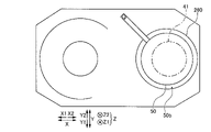
- the reflector preferably has a polygonal plate shape or a circular plate shape.
- the reflector when the reflector is in the shape of a polygonal plate, the reflector can be produced by cutting the sheet metal in a straight line. Therefore, the reflector can be produced more easily than in the case of curvilinear cutting.
- the shape of the shutter is generally disk-shaped, when the reflector is a circular plate, the reflector can be shaped to match the shape of the disk-shaped shutter.
- the surface area of the reflector is too large, gas will adhere (adsorb) to the surface of the reflector, making it difficult to obtain a high vacuum in the vacuum chamber. The quality of the thin film formed on the surface is deteriorated.
- the shape of the reflector circular, it is possible to make the area of the reflector larger than that of the shutter and minimize it in accordance with the shape of the disk-shaped shutter. Therefore, the amount of gas adsorbed on the surface of the reflector can be minimized. As a result, it is possible to prevent the gas adsorbed on the surface of the reflector from escaping into the vacuum chamber during film formation, thereby preventing deterioration in the quality of the thin film due to failure to obtain a high vacuum.
- the reflector plate in the shape of a circular plate with no corners it is possible to suppress the concentration of the thermal stress caused by the heat radiated from the shutter at the corners. Therefore, by forming the reflector into a circular plate shape, deformation due to heat can be more suppressed than when the reflector includes corners.
- the reflector is arranged parallel to the exhaust pump-side surface of the retracted shutter arranged at the shutter retracted position and facing the exhaust pump-side surface of the shutter. It is With this configuration, the reflector is arranged in parallel to face the exhaust pump side surface of the shutter in the retracted state. can be reflected. Therefore, it is possible to more effectively suppress heat radiation from going around to the exhaust opening side, so that it is possible to more effectively suppress transfer of heat from the shutter to the exhaust pump.
- the reflector preferably includes a plurality of reflectors spaced apart from each other.
- the temperature of the reflector may rise due to heat radiation from the shutter.
- the heated reflector itself becomes a heat source, and heat is radiated from the heated reflector to the exhaust pump.
- the present invention includes a plurality of reflectors spaced apart from each other.
- the exhaust pump is preferably configured to cool and exhaust the gas in the vacuum chamber, and the reflector cools and exhausts the gas in the vacuum chamber. It is arranged between the pump and the retracted shutter arranged at the shutter retracted position. With this configuration, heat radiation from the retracted shutter arranged at the shutter retracted position can be reflected by the reflecting plate, so that the exhaust pump that cools and exhausts the gas is heated. It is possible to effectively suppress heat transfer from the shutter. As a result, it is possible to effectively prevent the gas adsorbed by the exhaust pump from being released into the vacuum chamber due to the heat from the shutter.
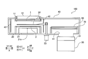
- FIG. 1 is a diagram showing the configuration of a sputtering apparatus according to one embodiment of the present invention
- FIG. FIG. 4 is a diagram for explaining movement of a shutter between a shutter closed position and a shutter retracted position
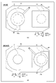
- FIG. 4A is a diagram for explaining the operation of the shutter of the sputtering apparatus, where (A) is a diagram showing the shutter in the closed state arranged at the shutter closed position, and (B) is arranged at the shutter retracted position
- FIG. 10 is a diagram showing the shutter in the retracted state
- FIG. 4 is a diagram showing two reflectors and a retracted shutter; It is the figure which showed an example of the reflector by a modification.
- FIG. 1 A sputtering apparatus 100 according to the present embodiment will be described with reference to FIGS. 1 to 4.
- FIG. 1 A sputtering apparatus 100 according to the present embodiment will be described with reference to FIGS. 1 to 4.
- FIG. 1 A sputtering apparatus 100 according to the present embodiment will be described with reference to FIGS. 1 to 4.
- FIG. 1 A sputtering apparatus 100 according to the present embodiment will be described with reference to FIGS. 1 to 4.
- the sputtering apparatus 100 is configured to form a thin film on the film-forming object 2 by sputtering the target 1 by sputtering particles from the sputtered target 1 .
- sputtering apparatus 100 introduces gases such as Ar (argon) and O 2 (oxygen) into vacuum chamber 40 evacuated, for example.
- the sputtering apparatus 100 applies a voltage to the target 1 to generate plasma in the vacuum chamber 40 .
- the charged particles (for example, argon ions) in the plasma collide with the target 1 , whereby sputtered particles (for example, atoms of the target 1 ) are emitted (thrusted out) from the target 1 .
- a thin film is formed on the surface of the film-forming object 2 by the sputtered particles adhering (film-forming) to the film-forming object 2 .
- the sputtering apparatus 100 includes a cathode electrode 11 and a magnet unit 12.
- a target 1 is arranged in the sputtering apparatus 100 .
- the target 1 is placed in the vacuum chamber 40 and generates sputtered particles for forming a thin film on the film-forming object 2 . That is, the target 1 is a member that becomes a material for the thin film formed on the film-forming object 2 .
- Target 1 contains, for example, aluminum or copper.
- the cathode electrode 11 is connected to a power supply (not shown) and applies negative charge to the target 1 . Specifically, the cathode electrode 11 generates a plasma discharge phenomenon in the vacuum chamber 40 by applying a negative DC high voltage to the target 1 . Also, the cathode electrode 11 is insulated from the vacuum chamber 40 . Note that the target 1 may be configured to be applied with an AC voltage, a pulse voltage, or a high frequency voltage.
- the magnet unit 12 is arranged on the back side of the target 1 (the side opposite to the side where the film-forming object 2 is arranged; Z1 direction side).
- the magnet unit 12 generates a leakage magnetic flux on the surface side of the target 1 (film-forming object 2 side; Z2 direction side). Electrons circulate in the vicinity of the surface of the target 1 on the film-forming object 2 side in the vacuum chamber 40 due to the leakage magnetic flux (magnetic field) from the magnet unit 12 .
- the sputtering apparatus 100 is configured to perform magnetron sputtering in which the magnet unit 12 circulates electrons to promote the generation of sputtered particles.
- the sputtering apparatus 100 also includes a mounting table 20 and a heating section 21 .
- the film-forming object 2 is mounted on the mounting table 20 in the vacuum chamber 40 .
- a thin film is formed on the surface of the film-forming object 2 by sputtering.
- the film-forming object 2 is, for example, a silicon wafer.
- the mounting table 20 is configured to move up and down by a lifting mechanism such as a motor (not shown).
- the heating unit 21 is configured to heat the film-forming object 2 mounted on the mounting table 20 .
- the heating unit 21 has a heating surface 21a along the XY plane on the side (Z1 direction side) on which the film-forming target 2 is arranged.
- the heating unit 21 is configured to heat the film-forming object 2 mounted on the mounting table 20 from the Z2 direction side with the heat from the heating surface 21a. That is, the heating unit 21 is configured to heat the film-forming object 2 from the side opposite to the side (Z1 direction side) where the target 1 and the shutter 50 are arranged.
- Heating unit 21 includes, for example, a heating wire.
- the heating surface 21a is an example of "the surface of the heating unit on the side where the film-forming object is arranged" in the claims.
- the heating surface 21a is not limited to a smooth plane, and may have an uneven shape.
- the surface connecting the vertexes of the convex portions of the uneven shape of the heating surface 21a is an example of the "surface of the heating section on the side on which the object to be film-formed is arranged.”
- the sputtering apparatus 100 also includes an exhaust pump 30 and an exhaust adjustment valve 31 .
- the exhaust pump 30 evacuates the vacuum chamber 40 .
- the exhaust pump 30 cools and exhausts the gas in the vacuum chamber 40 .
- Exhaust pump 30 is, for example, a cryopump.
- the exhaust pump 30 condenses the gas in the vacuum chamber 40 by cooling it to a low temperature of about 100K (Kelvin) or less, for example.
- the exhaust pump 30 is configured to adsorb (trap) the condensed gas.
- the exhaust adjustment valve 31 adjusts the flow rate of exhaust by the exhaust pump 30 .
- the exhaust adjustment valve 31 is connected to an exhaust opening 41 of a vacuum chamber 40, which will be described later.
- the sputtering apparatus 100 also includes a vacuum chamber 40 .
- the vacuum chamber 40 has a target 1 and a film-forming object 2 arranged therein for sputtering.
- the vacuum chamber 40 is evacuated by the exhaust pump 30 to form a vacuum state.
- the target 1 is arranged on the Z1 direction side
- the film-forming object 2 is arranged on the Z2 direction side.
- the vacuum chamber 40 also includes an exhaust opening 41 .
- the exhaust opening 41 is an opening to which the exhaust pump 30 is connected. That is, the exhaust pump 30 is configured to exhaust the gas inside the vacuum chamber 40 through the exhaust opening 41 .
- the exhaust opening 41 is, for example, a circular opening (see FIG. 3B).
- the exhaust opening 41 is provided on the bottom surface of the vacuum chamber 40 (surface on the Z2 direction side) near the X2 direction side.
- the sputtering apparatus 100 also includes an anti-adhesion plate 42 inside the vacuum chamber 40 .
- the anti-adhesion plate 42 is a shield plate for suppressing adhesion of sputtered particles to the inner surface of the vacuum chamber 40 .
- the anti-adhesion plate 42 is a semi-cylindrical (see FIG. 3) plate-like member extending along the direction (Z direction) in which the target 1 and the film-forming object 2 face each other.
- the sputtering apparatus 100 includes a shutter 50 and a shutter drive mechanism 53.
- the shutter 50 has a disc shape having an upper surface 51 on the Z1 direction side and a lower surface 52 on the Z2 direction side.
- the shutter 50 is, for example, stainless steel (SUS304, SUS316).
- the shutter 50 shields the film-forming object 2 so that sputtered particles from the target 1 do not adhere to the film-forming object 2 .
- the lower surface 52 is an example of "one surface", “surface on the side facing the reflector", and “surface on the exhaust pump side” in the claims.
- sputtering target cleaning
- the sputtering apparatus 100 uses the shutter 50 to shield the film-forming object 2 and the target to prevent the sputtered particles from adhering (depositing) to the film-forming object 2 during the target cleaning. 1 is sputtered.
- the sputtering apparatus 100 retracts the shutter 50 from between the target 1 and the film-forming object 2 to form a thin film on the film-forming object 2. Sputtering is performed for
- the shutter 50 has a shutter closed position 50a that shields the film-forming object 2 from the target 1, and a shutter retracted position 50b that moves from the shutter closed position 50a toward the exhaust pump 30 and is arranged during film formation. and can be moved. Specifically, the rotation of the shutter drive mechanism 53 about the Z direction causes the shutter 50 to move along the XY plane between the shutter closed position 50a and the shutter retracted position 50b.
- the shutter closed position 50 a is the position where the shutter 50 is arranged between the target 1 and the film-forming object 2 within the vacuum chamber 40 .
- the closed shutter 50 arranged at the shutter closed position 50a shields the film-forming object 2 so as to cover it.
- a shutter retreat position 50b is a position where the shutter 50 is retreated toward the exhaust pump 30 from the shutter closed position 50a.
- the retracted shutter 50 arranged at the shutter retracted position 50b overlaps the exhaust opening 41 of the vacuum chamber 40 when viewed from a direction perpendicular to the surface of the shutter 50 (a direction along the vertical direction). overlapping). That is, the retracted shutter 50 is arranged so as to overlap the exhaust opening 41 when viewed in the Z direction.
- the shutter closed position 50a is closer to the X1 direction, and the shutter retracted position 50b is moved from the shutter closed position 50a to the X2 direction.
- the sputtering apparatus 100 includes two reflectors 60 and 70 .
- the reflectors 60 and 70 reflect heat radiation from the retracted shutter 50 to the exhaust pump 30 .
- the reflectors 60 and 70 respectively have upper surfaces 61 and 71 on the side facing the retracted shutter 50 in the Z1 direction.
- Reflectors 60 and 70 also have lower surfaces 62 and 72 on the Z2 direction side, respectively.
- the upper surfaces 61 and 71 are an example of "the surface on the side facing the retracted shutter arranged at the shutter retracted position" in the claims.
- the reflectors 60 and 70 are rectangular plates. Reflectors 60 and 70 have substantially the same shape. Also, reflectors 60 and 70 are, for example, stainless steel. The reflectors 60 and 70 may be made of a material and have a thickness that does not transmit infrared rays (heat rays). Moreover, it is preferable that the reflectors 60 and 70 are made of a material having high heat resistance and a high infrared reflectance on the surface. In the present embodiment, at least part of the surface of the reflectors 60 and 70 on the side (Z1 direction side) facing the retracted shutter 50 arranged at the shutter retracted position 50b is a mirror surface.
- the two reflectors 60 and 70 have upper surfaces so as to easily reflect thermal radiation (infrared rays) and prevent gas from adhering to the surfaces of the reflectors 60 and 70 .
- the entire surfaces 61 and 71 and the lower surfaces 62 and 72 are polished mirror surfaces.
- the reflectors 60 and 70 are configured to reflect heat radiation from the retracted shutter 50 that is not cooled and is placed at the shutter retracted position 50b. That is, the sputtering apparatus 100 according to the present embodiment is not provided with a structure (such as a coolant channel) for cooling the reflecting plates 60 and 70 .
- reflectors 60 and 70 are spaced apart from each other along the Z direction.
- the reflectors 60 and 70 are arranged to face each other and parallel to each other (along the parallel direction).
- both reflectors 60 and 70 are arranged parallel to the XY plane (in a direction along parallel).
- the reflectors 60 and 70 are arranged so as to overlap each other.
- the reflectors 60 and 70 are arranged so as to reflect heat radiation from the lower surface 52 of the shutter 50 on the heated side.
- the heating unit 21 is arranged on the lower surface 52 side (Z2 direction side) of the closed shutter 50 arranged at the shutter closed position 50a.
- the reflectors 60 and 70 are arranged on the lower surface 52 side (Z2 direction side) common to the heating unit 21 with respect to the retracted shutter 50 arranged at the shutter retracted position 50b.
- the surfaces (upper surfaces 61 and 71) of the reflectors 60 and 70 on the side (Z1 direction side) facing the retracted shutter 50 arranged at the shutter retracted position 50b are the film-forming object. 2 is parallel to the surface (heating surface 21a) of the heating unit 21 on the side (Z1 direction side) (arranged in the parallel direction). Specifically, a heating surface 21a (surface on the Z1 direction side), which is the surface of the heating unit 21 on the film formation target 2 side, is arranged parallel to the XY plane. Similarly, upper surfaces 61 and 71 (surfaces on the Z1 direction side) of reflectors 60 and 70 are arranged parallel to the XY plane.
- the reflectors 60 and 70 are parallel (along parallel) to the lower surface 52, which is the surface on the side of the exhaust pump 30 (Z2 direction side) of the retracted shutter 50 arranged at the shutter retracted position 50b. direction) and faces the lower surface 52 of the shutter 50 on the side of the exhaust pump 30 . That is, both reflectors 60 and 70 are arranged parallel to and facing the lower surface 52 of the retracted shutter 50 .
- the reflectors 60 and 70 may bend in the Z direction due to their own weight or thermal expansion caused by radiant heat from the shutter 50 .
- the reflectors 60 and 70 may be arranged parallel to the heating surface 21a when the sputtering apparatus 100 is assembled (manufactured).
- reflectors 60 and 70 may be arranged parallel to lower surface 52 of shutter 50 in the retracted state when sputtering apparatus 100 is assembled (manufactured).
- the reflectors 60 and 70 are arranged between the exhaust pump 30 and the retracted shutter 50 arranged at the shutter retracted position 50b. Specifically, the reflectors 60 and 70 are arranged at a position that shields the exhaust opening 41 from the retracted shutter 50 arranged at the shutter retracted position 50b. In this embodiment, the reflectors 60 and 70 are provided between the exhaust opening 41 of the vacuum chamber 40 to which the exhaust pump 30 is connected and the retracted shutter 50 arranged at the shutter retracting position 50b. It is arranged apart from both the portion 41 and the shutter 50 in the retracted state. Specifically, the reflectors 60 and 70 are arranged between the retracted shutter 50 and the exhaust opening 41 at positions spaced apart from both the shutter 50 and the exhaust opening 41 in the Z direction.
- the reflectors 60 and 70 are in the retracted state when viewed from a direction perpendicular to the surface of the reflectors 60 and 70 (a direction along the vertical direction). 50 and the exhaust opening 41 are arranged to overlap. Specifically, the shutters 50 in the retracted state are arranged so as to overlap each other so as to cover the entire exhaust opening 41 when viewed from the Z direction side. The reflectors 60 and 70 are arranged overlapping each other so as to cover the entire shutter 50 and exhaust opening 41 when viewed from the Z-direction side.
- the projected areas of the surfaces of the plate-like reflectors 60 and 70 are arranged at the shutter retracted position 50b. It is larger than the projected area of the surface (lower surface 52) of the retracted shutter 50 on the side facing the reflectors 60 and 70 (the Z2 direction side). That is, the size of the reflectors 60 and 70 viewed from the Z direction side is larger than the size of the retracted shutter 50 viewed from the Z direction side.
- the shutter 50 is arranged between the exhaust pump 30 and the retracted shutter 50 arranged at the shutter retracted position 50b, and reflects heat radiation from the retracted shutter 50 to the exhaust pump 30.
- Plate-shaped reflectors 60 and 70 are provided.
- the heat radiation from the retracted shutter 50 arranged at the shutter retracted position 50b can be reflected by the reflectors 60 and . Therefore, heat transfer from the heated shutter 50 to the exhaust pump 30 can be suppressed.
- the heated shutter 50 is moved toward the exhaust pump 30 , it is possible to prevent the gas adsorbed by the exhaust pump 30 from being released into the vacuum chamber 40 .
- the heating unit 21 is arranged on the lower surface 52 (one surface) side of the closed shutter 50 arranged at the shutter closed position 50a, and the reflectors 60 and 70 , on the side of the lower surface 52 (one surface) common to the heating unit 21 with respect to the retracted shutter 50 arranged at the shutter retracted position 50b.
- the heating portion 21 and the reflectors 60 and 70 are arranged on the common lower surface 52 (one surface) side. Heat radiation from the 52 (one surface) side can be reflected by the reflectors 60 and 70 . Therefore, heat radiation from the lower surface 52 (one surface) of the shutter 50 that is heated can be suppressed from being transmitted to the exhaust pump 30 . can be effectively suppressed.
- the surfaces (upper surfaces 61 and 71) of the reflectors 60 and 70 on the side (Z1 direction side) facing the retracted shutter 50 arranged at the shutter retracted position 50b are It is parallel to the surface of the heating unit 21 on the side (Z1 direction side) on which the film-forming object 2 is arranged.
- Reflectors 60 and 70 can be arranged along the surface of 50 (lower surface 52).
- the reflection of heat by the reflectors 60 and 70 can keep the shutter 50 warm and keep it at a constant temperature, so that the temperature drop of the shutter 50 can be suppressed.
- the temperature decrease of the shutter 50 causes insufficient heating of the film-forming target 2. Therefore, it is possible to suppress the occurrence of defects in the formed thin film.
- the reflectors 60 and 70 are provided on the surfaces (upper surfaces 61 and 71) on the side (Z1 direction side) facing the retracted shutter 50 arranged at the shutter retracted position 50b.
- the entire surface is a mirror surface.
- the surfaces (upper surfaces 61 and 71) of the reflectors 60 and 70 on the side facing the retracted shutter 50 is a mirror surface, it is possible to prevent gas from adhering (remaining) to the reflectors 60 and 70. can be suppressed. Therefore, it is possible to suppress the occurrence of defects in the thin film formed on the film-forming object 2 due to the gas adhering (remaining) to the reflecting plates 60 and 70 .
- the reflectors 60 and 70 are configured to reflect heat radiation from the retracted shutter 50 arranged at the shutter retracted position 50b without being cooled.
- the plate-like reflectors 60 and 70 heat radiation from the shutter 50 is reflected and exhausted without providing a structure such as a coolant flow path for cooling the reflectors 60 and 70. Transfer of heat to the pump 30 can be easily suppressed. As a result, heat propagation to the exhaust pump 30 can be easily suppressed without complicating the device configuration.
- cooling of reflecting plates 60 and 70 lowers the temperature of retracted shutter 50 arranged at shutter retracting position 50b.
- the reflectors 60 and 70 are configured to reflect heat radiation from the retracted shutter 50 arranged at the shutter retracted position 50b without being cooled. Thereby, it is possible to suppress the temperature drop of the shutter 50 due to the cooling of the reflectors 60 and 70 . Therefore, it is possible to suppress the occurrence of defects in the thin film formed on the film-forming object 2 due to the temperature drop of the shutter 50 .
- the reflectors 60 and 70 are arranged between the exhaust opening 41 of the vacuum chamber 40 to which the exhaust pump 30 is connected and the retracted shutter 50 arranged at the shutter retracted position 50b. In between, it is spaced apart from both the exhaust opening 41 and the retracted shutter 50 .
- the reflectors 60 and 70 away from the exhaust opening 41, a gap is formed between the reflectors 60 and 70 and the exhaust opening 41, so that the exhaust efficiency of the exhaust pump 30 is reduced by the reflector. A decrease due to the installation of 60 and 70 can be suppressed. Therefore, the heat radiation to the exhaust pump 30 can be effectively reflected by the reflectors 60 and 70 without lowering the exhaust efficiency.
- the reflectors 60 and 70 apart from the shutter 50 in the retracted state, heat is directly transferred from the shutter 50 in the retracted state to the reflectors 60 and 70 (heat is transferred directly). conduction) can be suppressed. Therefore, the heat radiation from the shutter 50 can be reflected without the reflecting plates 60 and 70 themselves being directly heated by the shutter 50. , the heat radiation from the reflectors 60 and 70 can be suppressed from being transmitted to the exhaust pump 30 . As a result, it is possible to effectively prevent the gas adsorbed by the exhaust pump 30 from being released into the vacuum chamber 40 .
- the retracted shutter 50 arranged at the shutter retracted position 50b is located at the exhaust opening of the vacuum chamber 40 when viewed from the direction (Z direction) perpendicular to the surface of the shutter 50.
- 41, and the reflectors 60 and 70 are arranged to overlap the retracted shutter 50 and the exhaust opening 41 when viewed from the direction (Z direction) perpendicular to the surfaces of the reflectors 60 and 70. ing.
- the reflectors 60 and 70 are arranged so as to overlap the shutter 50 and the exhaust opening 41 in the retracted state when viewed from the direction perpendicular to the surfaces of the reflectors 60 and 70 (the Z direction).
- the heat radiation from the retracted shutter 50 arranged to overlap the exhaust opening 41 toward the exhaust opening 41 is reflected along the direction (Z direction) perpendicular to the surfaces of the reflectors 60 and 70. be able to. Therefore, the heat radiation reflected by the reflectors 60 and 70 is more suppressed from going around to the exhaust opening 41 side, compared to the case of reflecting heat radiation from directions other than the direction perpendicular to the reflectors 60 and 70. be able to. As a result, the transfer of heat to the exhaust pump 30 can be further suppressed.
- the projected areas of the surfaces of the plate-like reflectors 60 and 70 are arranged at the shutter retracted position 50b. larger than the projected area of the surface (lower surface 52) on the side (Z2 direction side) of shutter 50 in the retracted state facing reflecting plates 60 and 70. Accordingly, the heat radiation from the surface of the shutter 50 in the retracted state can be reflected by the reflectors 60 and 70 having a larger projected area than the surface (lower surface 52) of the shutter 50 in the retracted state.
- the reflectors 60 and 70 are polygonal (quadrangular) plates. As a result, when the reflectors 60 and 70 are rectangular plates, the reflectors 60 and 70 can be produced by cutting the sheet metal in a straight line. Therefore, the reflectors 60 and 70 can be produced more easily than in the case of curvilinear cutting.
- the reflectors 60 and 70 are parallel to the surface (lower surface 52) on the exhaust pump 30 side (Z2 direction side) of the retracted shutter 50 arranged at the shutter retracted position 50b. , is arranged so as to face the surface (lower surface 52) of the shutter 50 on the exhaust pump 30 side.
- the reflectors 60 and 70 are arranged in parallel to face the exhaust pump 30 side surface (lower surface 52) of the shutter 50 in the retracted state, heat radiation from the shutter 50 is blocked. It can be reflected perpendicular to the 50 side. Therefore, it is possible to more effectively suppress the radiation of heat from entering the exhaust opening 41 side, so that the transfer of heat from the shutter 50 to the exhaust pump 30 can be more effectively suppressed.
- the present embodiment includes a plurality of reflectors 60 and 70 that are spaced apart from each other.
- the temperature of reflectors 60 and 70 may rise due to heat radiation from shutter 50 .
- the temperature-increased reflectors 60 and 70 themselves become a heat source, and heat is radiated to the exhaust pump 30 from the temperature-increased reflectors 60 and 70 .
- the present embodiment includes a plurality of reflectors 60 and 70 spaced apart from each other. As a result, even when the temperature of the reflector 60 closer to the shutter 50 among the plurality of reflectors 60 and 70 rises, the adjacent reflector 70 reflects heat radiation from the reflector 60 whose temperature has risen.
- the exhaust pump 30 is configured to cool and exhaust the gas in the vacuum chamber 40, and the reflectors 60 and 70 cool the gas in the vacuum chamber 40. It is arranged between the exhaust pump 30 that cools and exhausts air and the retracted shutter 50 arranged at the shutter retracted position 50b. As a result, heat radiation from the retracted shutter 50 arranged at the shutter retracted position 50b can be reflected by the reflectors 60 and 70, so that the exhaust pump 30 that cools and exhausts the gas is heated. It is possible to effectively suppress heat transfer from the closed shutter 50 . As a result, it is possible to effectively prevent the gas adsorbed by the exhaust pump 30 from being released into the vacuum chamber 40 due to the heat from the shutter 50 .
- both the heating unit 21 and the reflectors 60 and 70 are arranged on the lower surface 52 side (Z2 direction side) of the shutter 50, but the present invention is limited to this. do not have.
- the heating unit 21 and the reflectors 60 and 70 may be arranged separately on the upper surface 51 side and the lower surface 52 side of the shutter 50 .
- the reflectors 60 and 70 are arranged on the side where the exhaust opening 41 is arranged as viewed from the shutter 50 .
- the upper surfaces 61 and 71 of the reflectors 60 and 70 are parallel to the heating surface 21a of the heating unit 21, but the present invention is not limited to this.
- the upper surfaces 61 and 71 of the reflectors 60 and 70 may intersect with the heating surface 21a of the heating unit 21 .
- the present invention is directed to this.
- the shutter 50 may be arranged obliquely with respect to the surface of the film-forming object 2 .
- the shutter 50 and the heating surface 21a of the heating unit 21 may be arranged not parallel to each other but obliquely by arranging the heating surface 21a of the heating unit 21 parallel to the surface of the film-forming object 2. .
- the reflectors 60 and 70 have mirror surfaces on both sides, but the present invention is not limited to this.
- reflectors 60 and 70 may be configured to have a mirror surface on only one side. Also, only part of one side may be a mirror surface. Alternatively, only one of the reflectors 60 and 70 may be configured to have a mirror surface.
- both reflectors 60 and 70 need not have a mirror surface.
- a surface treatment such that the difference cannot be recognized in the visible light range (the surface is not mirror-finished with the naked eye) is used. good too.
- the means for obtaining a mirror surface is not limited to polishing. That is, the surfaces of the reflectors 60 and 70 may be coated with a material other than stainless steel so as to effectively reflect heat radiation from the shutter 50 .
- the reflectors 60 and 70 are arranged apart from both the shutter 50 in the retracted state and the exhaust opening 41, but the present invention is not limited to this. .
- reflectors 60 and 70 may be provided to abut exhaust opening 41 .
- the retracted shutter 50 arranged at the shutter retracted position 50b is arranged so as to overlap the exhaust opening 41 when viewed from the direction (Z direction) perpendicular to the surface of the shutter 50.
- the retracted shutter 50 and the exhaust opening 41 may be arranged so as not to overlap each other when viewed from the direction perpendicular to the surface of the shutter 50 .
- the reflectors 60 and 70 and the retracted shutter 50 may be arranged to overlap (overlap), or the exhaust opening 41 and the reflectors 60 and 70 may overlap (overlap). be arranged). That is, the reflectors 60 and 70 should be arranged so that the shutter 50 cannot be seen (shielded) when viewed from the exhaust opening 41 .
- the projected area of the surfaces of the reflectors 60 and 70 is larger than the projected area of the surface (lower surface 52) of the shutter 50 in the retracted state facing the reflectors 60 and 70 (the Z2 direction side).
- the present invention is not limited to this.
- the projected area of the surfaces of reflectors 60 and 70 may be smaller than the area of the surface (lower surface 52) of shutter 50 on the side facing reflectors 60 and 70 (Z2 direction side). That is, the projected area of at least one reflector may be larger than the projected area of the shutter 50 , and the projected area of the other reflectors may be smaller than that of the shutter 50 .
- a plurality of reflectors smaller than the shutter 50 may be combined to have a larger projected area than the shutter 50 .
- reflectors 60 and 70 are square (rectangular) plates
- reflectors 60 and 70 may be polygonal plates such as triangles or pentagons.
- ribs may be provided on the rear surfaces of the reflectors 60 and 70 to suppress deformation.
- the reflectors 60 and 70 may be deformable (flexible) sheet-like or film-like.
- the reflector 260 may be in the shape of a circular plate. Since the shape of the shutter 50 is generally disk-shaped, when the reflector 260 is a circular plate, the reflector 260 can be shaped to match the shape of the disk-shaped shutter 50 . . Here, if the surface area of the reflecting plate 260 is too large, gas adheres (adsorbs) to the surface of the reflecting plate 260, making it difficult to obtain a high vacuum in the vacuum chamber 40. The quality of the thin film formed on the film object 2 is degraded.
- the area of the reflector 260 can be minimized in accordance with the shape of the disk-shaped shutter 50 while being larger than the area of the shutter 50 . . Therefore, the amount of gas adsorbed on the surface of the reflector 260 can be minimized. As a result, it is possible to suppress the gas adsorbed on the surface of the reflector 260 from jumping out into the vacuum chamber 40 during film formation, thereby suppressing deterioration in the quality of the thin film due to failure to obtain a high vacuum. can. Further, by forming the reflector 260 into a circular plate shape without corners, it is possible to suppress the thermal stress caused by the heat radiated from the shutter 50 from concentrating on the corners. Therefore, by forming the reflector 260 into a circular plate shape, deformation due to heat can be more suppressed than when the reflector 260 includes corner portions.
- the reflectors 60 and 70 are arranged in parallel with the lower surface 52 of the shutter 50 in the retracted state so as to face the lower surface 52 of the shutter 50.
- the present invention is similar to this. is not limited to
- the reflector 60 and the reflector 70 may be arranged so as to face the lower surface 52 of the shutter 50 in a tilted state rather than in parallel.
- the present invention is not limited to this.
- the number of reflectors may be one, or three or more.
- each of the plurality of reflectors may be made of a different material.
- the two reflectors 60 and 70 are arranged parallel to each other, but the present invention is not limited to this.
- the two (plurality) reflectors may be arranged so as to face each other in a tilted state instead of being parallel to each other.
- the two reflectors 60 and 70 have substantially the same shape, but the present invention is not limited to this.
- the two reflectors may have different shapes. That is, one of the two reflectors may be rectangular (polygonal) and the other circular.
- the reflecting plate 70 may be configured to have a larger area than the reflecting plate 60 .
- the shutter 50 was used to remove oxides on the surface of the target 1 (for target cleaning), but the present invention is not limited to this.
- the shutter 50 when performing sputtering without forming a film on the film-forming object 2 other than target cleaning, such as stabilization of plasma (discharge) or stabilization of the atmosphere in the vacuum chamber 40, the shutter 50 is set to the shutter closed position. You may arrange it.
- the shutter 50 has a circular plate shape, but the present invention is not limited to this.
- the shutter 50 may be polygonal, such as square.
- the area of the shutter 50 in the retracted state is larger than the opening area of the exhaust opening 41, but the present invention is not limited to this.
- the area of shutter 50 may be smaller than the opening area of exhaust opening 41 .
- the area of reflectors 60 and 70 may also be smaller than exhaust opening 41 .
- the shutter 50 is switched from the closed state to the retracted state by moving in parallel from the shutter closed position 50a to the shutter retracted position 50b, but the present invention is not limited to this.
- the shutter 50 may be configured to change its shape between the closed state of the shutter closed position 50a and the retracted state of the shutter retracted position 50b. That is, the shutter 50 may be configured such that it is shaped like a single plate in the closed state of the shutter closed position 50a and is folded in the retracted state of the shutter retracted position 50b.
- the exhaust pump 30 is a cryopump that exhausts the gas in the vacuum chamber 40 by cooling it, but the present invention is not limited to this.
- the exhaust pump that exhausts the gas in the vacuum chamber 40 may be an ion pump or getter pump that adsorbs the gas.
- the exhaust pump may be a turbo-molecular pump that rotates a rotor (rotating body) including turbine blades to eject gas molecules by blowing them off.
Landscapes
- Chemical & Material Sciences (AREA)
- Engineering & Computer Science (AREA)
- Chemical Kinetics & Catalysis (AREA)
- Physics & Mathematics (AREA)
- Organic Chemistry (AREA)
- Metallurgy (AREA)
- Mechanical Engineering (AREA)
- Materials Engineering (AREA)
- Analytical Chemistry (AREA)
- Plasma & Fusion (AREA)
- Condensed Matter Physics & Semiconductors (AREA)
- Power Engineering (AREA)
- Microelectronics & Electronic Packaging (AREA)
- Computer Hardware Design (AREA)
- Manufacturing & Machinery (AREA)
- General Physics & Mathematics (AREA)
- Crystallography & Structural Chemistry (AREA)
- Physical Vapour Deposition (AREA)
Abstract
Description
図1に示すように、スパッタリング装置100は、カソード電極11、および、磁石ユニット12、を備える。また、スパッタリング装置100には、ターゲット1が配置される。
図2に示すように、スパッタリング装置100は、シャッタ50およびシャッタ駆動機構53を備える。シャッタ50は、Z1方向側に上面51と、Z2方向側に下面52とを有する円板状である。また、シャッタ50は、たとえば、ステンレス鋼(SUS304、SUS316)である。シャッタ50は、ターゲット1からのスパッタ粒子が成膜対象物2に付着しないように、成膜対象物2を遮蔽する。なお、下面52は、請求の範囲における「一方表面」、「反射板に対向する側における表面」、および、「排気ポンプ側の表面」の一例である。
図4に示すように、本実施形態によるスパッタリング装置100は、2つの反射板60および反射板70を備える。反射板60および70は、退避状態のシャッタ50からの排気ポンプ30に対する熱の輻射を反射させる。また、反射板60および70は、それぞれ、Z1方向側の退避状態のシャッタ50に対向する側に上面61および71を有する。また、反射板60および70は、それぞれ、Z2方向側に下面62および72を有する。なお、上面61および71は、請求の範囲における「シャッタ退避位置に配置された退避状態のシャッタに対向する側における表面」の一例である。
本実施形態では、反射板60および70は、Z方向に沿って互いに離間して配置されている。そして、反射板60および70は、互いに対向するように配置されているとともに、互いに平行に(平行な方向に沿って)配置されている。具体的には、反射板60および70の両方は、XY平面に平行に(平行に沿った方向に)配置されている。そして、平面視において、反射板60および70は重なり合う(オーバーラップする)ように配置されている。
本実施形態では、以下のような効果を得ることができる。
なお、今回開示された実施形態は、すべての点で例示であって制限的なものではないと考えられるべきである。本発明の範囲は、上記した実施形態の説明ではなく請求の範囲によって示され、さらに請求の範囲と均等の意味および範囲内でのすべての変更が含まれる。
2 成膜対象物
21 加熱部
21a 加熱面(成膜対象物が配置される側における加熱部の表面)
30 排気ポンプ
40 真空チャンバ
41 排気開口部
50 シャッタ
50a シャッタ閉位置
50b シャッタ退避位置
52 下面(一方表面、排気ポンプ側の表面、反射板に対向する側における表面、排気ポンプ側の表面)
60、70、260 反射板(複数の反射板)
61、71 上面(シャッタ退避位置に配置された退避状態のシャッタに対向する側における表面)
100 スパッタリング装置
Claims (12)
- スパッタリングによる薄膜が形成される成膜対象物と、前記成膜対象物に前記薄膜を形成するためのスパッタ粒子を発生させるターゲットとが内部に配置される真空チャンバと、
前記成膜対象物を加熱する加熱部と、
前記真空チャンバ内の気体を排気する排気ポンプと、
前記ターゲットから前記成膜対象物を遮蔽するシャッタ閉位置と、前記シャッタ閉位置から前記排気ポンプ側に移動して成膜中に配置されるシャッタ退避位置とを移動可能に構成されているシャッタと、
前記排気ポンプと前記シャッタ退避位置に配置された退避状態の前記シャッタとの間に配置され、前記退避状態の前記シャッタからの前記排気ポンプに対する熱の輻射を反射させる板状の反射板と、を備える、スパッタリング装置。 - 前記加熱部は、前記シャッタ閉位置に配置された閉状態の前記シャッタの一方表面側に配置されており、
前記反射板は、前記シャッタ退避位置に配置された前記退避状態の前記シャッタに対して、前記加熱部と共通の前記一方表面側に配置されている、請求項1に記載のスパッタリング装置。 - 前記シャッタ退避位置に配置された前記退避状態の前記シャッタに対向する側における前記反射板の表面は、前記成膜対象物が配置される側における前記加熱部の表面と平行である、請求項1に記載のスパッタリング装置。
- 前記反射板は、前記シャッタ退避位置に配置された前記退避状態の前記シャッタに対向する側における表面の少なくとも一部が鏡面である、請求項1に記載のスパッタリング装置。
- 前記反射板は、冷却されずに、前記シャッタ退避位置に配置された前記退避状態の前記シャッタからの熱の輻射を反射させるように構成されている、請求項4に記載のスパッタリング装置。
- 前記反射板は、前記排気ポンプが接続される前記真空チャンバの排気開口部と前記シャッタ退避位置に配置された前記退避状態の前記シャッタとの間において、前記排気開口部と前記退避状態の前記シャッタとの両方から離間して配置されている、請求項1に記載のスパッタリング装置。
- 前記シャッタ退避位置に配置された前記退避状態の前記シャッタは、前記シャッタの表面に垂直な方向から視て、前記真空チャンバの前記排気開口部に重なるように配置され、
前記反射板は、前記反射板の表面に垂直な方向から視て、前記退避状態の前記シャッタおよび前記排気開口部に重なるように配置されている、請求項6に記載のスパッタリング装置。 - 前記シャッタの表面に垂直な方向から視て、板状の前記反射板の表面の投影面積は、前記シャッタ退避位置に配置された前記退避状態の前記シャッタの前記反射板に対向する側における表面の投影面積よりも大きい、請求項7に記載のスパッタリング装置。
- 前記反射板は、多角形の板状または円形の板状である、請求項8に記載のスパッタリング装置。
- 前記反射板は、前記シャッタ退避位置に配置された前記退避状態の前記シャッタにおける前記排気ポンプ側の表面と平行に、前記シャッタの前記排気ポンプ側の表面に対向するように配置されている、請求項1に記載のスパッタリング装置。
- 前記反射板は、互いに離間して配置される複数の前記反射板を含む、請求項1に記載のスパッタリング装置。
- 前記排気ポンプは、前記真空チャンバ内の気体を冷却して排気するように構成されており、
前記反射板は、前記真空チャンバ内の気体を冷却して排気する前記排気ポンプと前記シャッタ退避位置に配置された前記退避状態の前記シャッタとの間に配置されている、請求項1に記載のスパッタリング装置。
Priority Applications (3)
| Application Number | Priority Date | Filing Date | Title |
|---|---|---|---|
| JP2023510611A JP7547616B2 (ja) | 2021-03-29 | 2022-02-14 | スパッタリング装置 |
| CN202280023662.3A CN117043386A (zh) | 2021-03-29 | 2022-02-14 | 溅射装置 |
| US18/283,870 US20240162021A1 (en) | 2021-03-29 | 2022-02-14 | Sputtering Apparatus |
Applications Claiming Priority (2)
| Application Number | Priority Date | Filing Date | Title |
|---|---|---|---|
| JP2021-055065 | 2021-03-29 | ||
| JP2021055065 | 2021-03-29 |
Publications (1)
| Publication Number | Publication Date |
|---|---|
| WO2022209356A1 true WO2022209356A1 (ja) | 2022-10-06 |
Family
ID=83455890
Family Applications (1)
| Application Number | Title | Priority Date | Filing Date |
|---|---|---|---|
| PCT/JP2022/005657 WO2022209356A1 (ja) | 2021-03-29 | 2022-02-14 | スパッタリング装置 |
Country Status (4)
| Country | Link |
|---|---|
| US (1) | US20240162021A1 (ja) |
| JP (1) | JP7547616B2 (ja) |
| CN (1) | CN117043386A (ja) |
| WO (1) | WO2022209356A1 (ja) |
Citations (4)
| Publication number | Priority date | Publication date | Assignee | Title |
|---|---|---|---|---|
| JP2006016627A (ja) * | 2004-06-30 | 2006-01-19 | Nec Kansai Ltd | 真空蒸着装置 |
| WO2011067820A1 (ja) * | 2009-12-04 | 2011-06-09 | キヤノンアネルバ株式会社 | スパッタリング装置、及び電子デバイスの製造方法 |
| WO2011117945A1 (ja) * | 2010-03-26 | 2011-09-29 | キヤノンアネルバ株式会社 | スパッタリング装置及び電子デバイスの製造方法 |
| WO2013094200A1 (ja) * | 2011-12-22 | 2013-06-27 | キヤノンアネルバ株式会社 | 基板処理装置 |
Family Cites Families (3)
| Publication number | Priority date | Publication date | Assignee | Title |
|---|---|---|---|---|
| JP4473410B2 (ja) * | 2000-05-24 | 2010-06-02 | キヤノンアネルバ株式会社 | スパッタリング装置及び成膜方法 |
| US20040084305A1 (en) * | 2002-10-25 | 2004-05-06 | Semiconductor Energy Laboratory Co., Ltd. | Sputtering system and manufacturing method of thin film |
| CN110808384B (zh) * | 2019-10-11 | 2021-04-27 | 浙江锋源氢能科技有限公司 | 一种金属双极板及其制备方法以及燃料电池 |
-
2022
- 2022-02-14 CN CN202280023662.3A patent/CN117043386A/zh active Pending
- 2022-02-14 JP JP2023510611A patent/JP7547616B2/ja active Active
- 2022-02-14 WO PCT/JP2022/005657 patent/WO2022209356A1/ja active Application Filing
- 2022-02-14 US US18/283,870 patent/US20240162021A1/en active Pending
Patent Citations (4)
| Publication number | Priority date | Publication date | Assignee | Title |
|---|---|---|---|---|
| JP2006016627A (ja) * | 2004-06-30 | 2006-01-19 | Nec Kansai Ltd | 真空蒸着装置 |
| WO2011067820A1 (ja) * | 2009-12-04 | 2011-06-09 | キヤノンアネルバ株式会社 | スパッタリング装置、及び電子デバイスの製造方法 |
| WO2011117945A1 (ja) * | 2010-03-26 | 2011-09-29 | キヤノンアネルバ株式会社 | スパッタリング装置及び電子デバイスの製造方法 |
| WO2013094200A1 (ja) * | 2011-12-22 | 2013-06-27 | キヤノンアネルバ株式会社 | 基板処理装置 |
Also Published As
| Publication number | Publication date |
|---|---|
| CN117043386A (zh) | 2023-11-10 |
| JP7547616B2 (ja) | 2024-09-09 |
| JPWO2022209356A1 (ja) | 2022-10-06 |
| US20240162021A1 (en) | 2024-05-16 |
Similar Documents
| Publication | Publication Date | Title |
|---|---|---|
| JP6412984B2 (ja) | カルーセル原子層堆積のための装置および方法 | |
| JP4537479B2 (ja) | スパッタリング装置 | |
| JP4484974B2 (ja) | 加熱及び冷却真空チャンバシールド | |
| EP0679730B1 (en) | Shield configuration for vacuum chamber | |
| US9252002B2 (en) | Two piece shutter disk assembly for a substrate process chamber | |
| US20190348264A1 (en) | Pre-clean chamber with integrated shutter garage | |
| JP6246961B2 (ja) | 成膜装置 | |
| TWI467692B (zh) | Substrate processing method and substrate processing device | |
| US11043406B2 (en) | Two piece shutter disk assembly with self-centering feature | |
| JP2005076046A (ja) | 薄膜作成装置 | |
| JP2001271164A (ja) | 基板処理システムのための冷却システムを有する磁電管 | |
| JP2007131883A (ja) | 成膜装置 | |
| WO2022209356A1 (ja) | スパッタリング装置 | |
| CN114015997A (zh) | 一种离子辅助的多靶磁控溅射设备 | |
| KR101841980B1 (ko) | 성막 장치 | |
| TWI807165B (zh) | 物理氣相沉積方法 | |
| KR102597416B1 (ko) | 진공 처리 장치 | |
| KR101515048B1 (ko) | 캐소드 | |
| JP4313480B2 (ja) | 基板加熱チャンバー及びこの基板加熱チャンバーを備えた情報記録ディスク用基板処理装置、並びに基板加熱処理装置 | |
| JP7531680B2 (ja) | カソードユニットおよび成膜装置 | |
| JP7316877B2 (ja) | 真空プロセス装置および真空プロセス装置におけるプロセス対象物の冷却方法 | |
| JP7362327B2 (ja) | ターゲット構造体及び成膜装置 | |
| JP4378017B2 (ja) | 光ディスク用スパッタ装置 | |
| JP2005228674A (ja) | イオン注入装置 | |
| JP2005290464A (ja) | スパッタリング装置及び方法 |
Legal Events
| Date | Code | Title | Description |
|---|---|---|---|
| 121 | Ep: the epo has been informed by wipo that ep was designated in this application |
Ref document number: 22779583 Country of ref document: EP Kind code of ref document: A1 |
|
| ENP | Entry into the national phase |
Ref document number: 2023510611 Country of ref document: JP Kind code of ref document: A |
|
| WWE | Wipo information: entry into national phase |
Ref document number: 202280023662.3 Country of ref document: CN |
|
| WWE | Wipo information: entry into national phase |
Ref document number: 18283870 Country of ref document: US |
|
| NENP | Non-entry into the national phase |
Ref country code: DE |
|
| 122 | Ep: pct application non-entry in european phase |
Ref document number: 22779583 Country of ref document: EP Kind code of ref document: A1 |