WO2022208829A1 - 内燃機関の吸気構造 - Google Patents
内燃機関の吸気構造 Download PDFInfo
- Publication number
- WO2022208829A1 WO2022208829A1 PCT/JP2021/014094 JP2021014094W WO2022208829A1 WO 2022208829 A1 WO2022208829 A1 WO 2022208829A1 JP 2021014094 W JP2021014094 W JP 2021014094W WO 2022208829 A1 WO2022208829 A1 WO 2022208829A1
- Authority
- WO
- WIPO (PCT)
- Prior art keywords
- intake passage
- fuel injection
- combustion chamber
- internal combustion
- combustion engine
- Prior art date
- Legal status (The legal status is an assumption and is not a legal conclusion. Google has not performed a legal analysis and makes no representation as to the accuracy of the status listed.)
- Ceased
Links
Images




Classifications
-
- F—MECHANICAL ENGINEERING; LIGHTING; HEATING; WEAPONS; BLASTING
- F02—COMBUSTION ENGINES; HOT-GAS OR COMBUSTION-PRODUCT ENGINE PLANTS
- F02B—INTERNAL-COMBUSTION PISTON ENGINES; COMBUSTION ENGINES IN GENERAL
- F02B31/00—Modifying induction systems for imparting a rotation to the charge in the cylinder
- F02B31/02—Modifying induction systems for imparting a rotation to the charge in the cylinder in engines having inlet valves arranged eccentrically to cylinder axis
-
- F—MECHANICAL ENGINEERING; LIGHTING; HEATING; WEAPONS; BLASTING
- F02—COMBUSTION ENGINES; HOT-GAS OR COMBUSTION-PRODUCT ENGINE PLANTS
- F02B—INTERNAL-COMBUSTION PISTON ENGINES; COMBUSTION ENGINES IN GENERAL
- F02B31/00—Modifying induction systems for imparting a rotation to the charge in the cylinder
- F02B31/04—Modifying induction systems for imparting a rotation to the charge in the cylinder by means within the induction channel, e.g. deflectors
-
- F—MECHANICAL ENGINEERING; LIGHTING; HEATING; WEAPONS; BLASTING
- F02—COMBUSTION ENGINES; HOT-GAS OR COMBUSTION-PRODUCT ENGINE PLANTS
- F02M—SUPPLYING COMBUSTION ENGINES IN GENERAL WITH COMBUSTIBLE MIXTURES OR CONSTITUENTS THEREOF
- F02M69/00—Low-pressure fuel-injection apparatus ; Apparatus with both continuous and intermittent injection; Apparatus injecting different types of fuel
-
- F—MECHANICAL ENGINEERING; LIGHTING; HEATING; WEAPONS; BLASTING
- F02—COMBUSTION ENGINES; HOT-GAS OR COMBUSTION-PRODUCT ENGINE PLANTS
- F02M—SUPPLYING COMBUSTION ENGINES IN GENERAL WITH COMBUSTIBLE MIXTURES OR CONSTITUENTS THEREOF
- F02M69/00—Low-pressure fuel-injection apparatus ; Apparatus with both continuous and intermittent injection; Apparatus injecting different types of fuel
- F02M69/04—Injectors peculiar thereto
-
- Y—GENERAL TAGGING OF NEW TECHNOLOGICAL DEVELOPMENTS; GENERAL TAGGING OF CROSS-SECTIONAL TECHNOLOGIES SPANNING OVER SEVERAL SECTIONS OF THE IPC; TECHNICAL SUBJECTS COVERED BY FORMER USPC CROSS-REFERENCE ART COLLECTIONS [XRACs] AND DIGESTS
- Y02—TECHNOLOGIES OR APPLICATIONS FOR MITIGATION OR ADAPTATION AGAINST CLIMATE CHANGE
- Y02T—CLIMATE CHANGE MITIGATION TECHNOLOGIES RELATED TO TRANSPORTATION
- Y02T10/00—Road transport of goods or passengers
- Y02T10/10—Internal combustion engine [ICE] based vehicles
- Y02T10/12—Improving ICE efficiencies
Definitions
- the present invention relates to an intake structure for an internal combustion engine.
- An internal combustion engine has an intake passage leading to a combustion chamber and a fuel injection valve provided in the intake passage.
- a configuration is disclosed in which a tumble is held near the center of the combustion chamber (for example, Patent Document 1).
- the intake passage is divided into an upper intake passage and a lower intake passage through a partition wall in order to generate a tumble flow, and the cross-sectional area of the lower intake passage is larger than that of the main intake passage.
- a configuration with a small value for example, Patent Document 2.
- the present invention has been made in view of the circumstances described above, and an object of the present invention is to provide an intake structure for an internal combustion engine that facilitates obtaining an air-fuel mixture that is advantageous for improving combustion efficiency.
- An intake passage leading to a combustion chamber and a fuel injection device provided in the intake passage the intake passage being separated from the combustion chamber in the vertical direction corresponding to the axial direction of the combustion chamber and a main intake passage.
- an auxiliary intake passage wherein the auxiliary intake passage has a cross-sectional area smaller than that of the main intake passage, wherein the auxiliary intake passage is positioned on either side of the axis of the combustion chamber. and the injection direction of the fuel injection device is oriented in the one direction with respect to the axis of the combustion chamber.
- downstream side cross-sectional area of the auxiliary intake passage may be smaller than the upstream side cross-sectional area of the auxiliary intake passage.
- the fuel injection device has a fuel injection valve and a valve mounting member to which the fuel injection valve is mounted, and the valve mounting member is fastened to the main intake passage or the combustion chamber.
- the fuel injection valve and the fastening portion may be arranged so as to be distributed to one side and the other side with respect to the center of the main intake passage.
- the fuel injection valve and the fastening portion may at least partially overlap the main intake passage when viewed from above.
- the internal combustion engine includes a breather hose through which blow-by gas of the internal combustion engine passes, and the breather hose is positioned on the opposite side of the fastening portion with respect to the center of the main intake passage.
- the fuel injection valve of the fuel injection device is located on the opposite side of the axis of the combustion chamber from the side to which the injection direction is directed, with respect to the center of the main intake passage. good too.
- the auxiliary intake passage and the injection direction of the fuel injection device may be directed to the opposite side of the ignition plug with respect to the axis of the combustion chamber.
- An intake passage leading to a combustion chamber and a fuel injection device provided in the intake passage the intake passage being separated from the combustion chamber in the vertical direction corresponding to the axial direction of the combustion chamber and a main intake passage.
- an auxiliary intake passage wherein the auxiliary intake passage has a cross-sectional area smaller than that of the main intake passage, wherein the auxiliary intake passage is positioned on either side of the axis of the combustion chamber. and the injection direction of the fuel injector is directed to the one-way position with respect to the axis of the combustion chamber.
- the downstream side cross-sectional area of the auxiliary intake passage may be smaller than the upstream side cross-sectional area of the auxiliary intake passage. According to this configuration, the flow velocity of the air flowing into the combustion chamber from the auxiliary intake passage is increased, and the mixing of the air and the fuel can be further promoted.
- the fuel injection device has a fuel injection valve and a valve mounting member to which the fuel injection valve is mounted, and the valve mounting member is fastened to the main intake passage or the combustion chamber.
- the fuel injection valve and the fastening portion may be arranged so as to be distributed to one side and the other side with respect to the center of the main intake passage. According to this configuration, it is easy to prevent the fuel injection valve and the valve mounting member from being arranged to protrude on one side and the other side of the main intake passage.
- the fuel injection valve and the fastening portion may at least partially overlap the main intake passage when viewed from above. According to this configuration, it becomes easy to arrange the fuel injection valve and the valve mounting member in a compact manner by utilizing the empty space that overlaps with the main intake passage in a top view.
- the internal combustion engine includes a breather hose through which blow-by gas of the internal combustion engine passes, and the breather hose is positioned on the opposite side of the fastening portion with respect to the center of the main intake passage.
- the fuel injection valve of the fuel injection device is located on the opposite side of the axis of the combustion chamber from the side to which the injection direction is directed, with respect to the center of the main intake passage. good too. According to this configuration, it is possible to suppress adhesion of fuel to the wall surface of the intake passage and the wall surface of the combustion chamber.
- the auxiliary intake passage and the injection direction of the fuel injection device may be directed to the opposite side of the ignition plug with respect to the axis of the combustion chamber. According to this configuration, the spark plug hardly obstructs the swirl flow generated in the combustion chamber by the air from the auxiliary intake passage.
- FIG. 1 is a view showing the left side of a power unit having an air intake structure of the present invention together with its peripheral configuration.
- FIG. 2 is a diagram showing the top surface of the power unit together with the peripheral configuration.
- FIG. 3 is a side sectional view of the periphery of the cylinder head of the power unit.
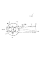
- FIG. 4 is a diagram showing the inlet pipe and a part of the peripheral structure as viewed from the crankshaft side along the cylinder axis.
- FIG. 5 is a diagram in which the description related to the fuel injection device is deleted from FIG. 4 and the central axis line LB of the auxiliary intake passage is added.
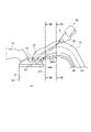
- FIG. 6 is a view showing the inlet pipe together with a part of the peripheral structure from the side of the cylinder. 7 is a cross-sectional view taken along line VII-VII of FIG. 5.
- FIG. 8 is a cross-sectional view taken along line VIII-VIII of FIG. 6.
- directions such as front, rear, left, right, and up and down are directions based on the vehicle body unless otherwise specified.
- Symbol FR shown in each figure indicates the front of the vehicle body
- symbol UP indicates the upper part of the vehicle body
- symbol LH indicates the left side of the vehicle body.
- FIG. 1 is a view showing the left side of a power unit 1 having an air intake structure of the present invention together with its peripheral structure
- FIG. 2 is a view showing the upper surface of the power unit 1 together with its peripheral structure.
- the power unit 1 is a power unit supported by a body frame of a scooter type motorcycle so as to be vertically swingable, and is also called a swing type power unit.
- the power unit 1 includes a crankcase 3 that rotatably supports a crankshaft 2 at the front, a cylinder block 4 provided at the front of the crankcase 3, and a It has a mounted cylinder head 5 and a head cover 6 closing an opening of the cylinder head 5.
- - ⁇ A cylinder portion consisting of a cylinder block 4, a cylinder head 5 and a head cover 6 is tilted forward from the front portion of the crankcase 3 to a state substantially close to water.
- a portion consisting of the crankcase 3 , the cylinder block 4 , the cylinder head 5 and the head cover 6 constitutes a single-cylinder four-stroke cycle air-cooled internal combustion engine (hereinafter simply referred to as the "internal combustion engine") 10 .
- a power transmission case portion 11 is connected to the left side of the crankcase 3 .
- the power transmission case portion 11 accommodates a belt-type continuously variable transmission that changes the speed of the rotation of the crankshaft 2 and transmits it to the rear wheel shaft 12 .
- the inlet pipe 15 extends from the upper part of the cylinder head 5, curves backward, and is connected to the throttle body 16.
- An air cleaner device 18 is connected to the rear end of the throttle body 16 via a connecting tube 17 .
- the air cleaner device 18 is arranged above the power transmission case portion 11 .
- a throttle valve (not shown) is provided in the throttle body 16, and the amount of intake air to the internal combustion engine 10 is adjusted by the throttle valve.
- the inlet pipe 15 , throttle body 16 and connecting tube 17 form part of an intake passage 50 that supplies air cleaned by the air cleaner device 18 to the internal combustion engine 10 .
- an exhaust pipe 19 extends from the bottom of the cylinder head 5. After extending to the right side of the cylinder head 5 , the exhaust pipe 19 extends rearward and is connected to a muffler 20 .
- Reference numeral LC in FIG. 2 denotes a center line extending linearly in the front-rear direction through the left-right center of the inlet pipe 15, and is hereinafter referred to as an "intake passage center line LC". This intake passage centerline LC also coincides with the left-right centerline of the power unit 1 .
- the head cover 6 is connected to a breather hose 21 through which blow-by gas passes.
- the breather hose 21 extends rightward from the upper portion of the head cover 6 and then extends rearward to be connected to the air cleaner device 18 .
- the breather hose 21 extends rearward through the head cover 6, the cylinder block 4, and the right side of the connecting tube 17 when viewed from above, and extends left rearward along the connecting tube 17. It extends obliquely and is connected to the air cleaner device 18 .
- FIG. 3 is a side cross-sectional view around the cylinder head 5 of the power unit 1.
- the cylinder block 4 has a plurality of fins 4F on its outer surface and cylinder bores 22 formed therein.
- a piston 23 is slidably provided in the cylinder bore 22 .
- the piston 23 is connected to the crankshaft 2 via a connecting rod, and the piston 23 slides in the cylinder bore 22 to rotate the crankshaft 2 .
- a space between the top surface of the piston 23 and the ceiling surface of the combustion chamber of the cylinder head 5 facing the top surface constitutes a combustion chamber 24 .
- reference character L0 denotes an axis that passes through the center of the combustion chamber 24 and coincides with the axis of the cylinder portion.
- the internal combustion engine of this embodiment employs a SOHC type two-valve system, and a valve mechanism 25 is provided in the space between the cylinder head 5 and the head cover 6 .
- the valve mechanism 25 includes a camshaft 26 to which the rotation of the crankshaft 2 is transmitted at half the rotation speed via a cam chain (not shown). Rotation of the camshaft 26 operates an intake valve 28 that opens and closes an intake port 27 via an intake cam and an intake rocker arm (not shown). The rotation of the camshaft 26 also operates an exhaust valve 30 that opens and closes the exhaust port 29 via an exhaust cam and an exhaust rocker arm (not shown).
- the intake port 27 is a passage that communicates the combustion chamber 24 and the inlet pipe 15, and constitutes a part of the intake passage 50.
- the exhaust port 29 is a passage that allows the combustion chamber 24 and the exhaust pipe 19 to communicate with each other.
- the valve mechanism 25 opens and closes the intake port 27 and the exhaust port 29 at timings corresponding to four cycles of intake stroke and exhaust stroke.
- a spark plug 31 is attached to the cylinder head 5 and has a tip facing a position avoiding the intake port 27 and the exhaust port 29 .
- the intake passage 50 of this embodiment has a structure that generates a tumble flow T (see FIG. 2) in the combustion chamber 24, that is, an intake structure that provides vertical rotation. More specifically, the intake passage 50 is separated from the combustion chamber 24 in the vertical direction corresponding to the direction of the axis L0 of the combustion chamber 24 by the partition wall 32 leading from the inlet pipe 15 to the intake port 27.
- an intake passage 50A hereinafter referred to as a main intake passage 50A
- auxiliary intake passage 50B hereinafter referred to as an auxiliary intake passage 50B
- the auxiliary intake passage 50B is formed as a tumble flow path for generating a tumble flow T within the combustion chamber 24. As shown in FIG.
- the auxiliary intake passage 50B is formed in a passage having a cross-sectional area (also referred to as a cross-sectional area) smaller than that of the main intake passage 50, and when the intake air amount of the internal combustion engine 10 is relatively small or in an idling state or a low speed rotation state, Air is supplied so that a tumble flow T can be generated. That is, when the opening degree of the throttle valve in the throttle body 16 located upstream of both intake passages 50A and 50B is relatively small, the air cleaned by the air cleaner device 18 mainly passes through the auxiliary intake passage 50B. , to generate a tumble flow T.
- the main intake passage 50A functions as a passage for sufficiently supplying air when the internal combustion engine 10 has a relatively large amount of intake air and is in a medium/high speed rotation state or an acceleration state. That is, when the opening of the throttle valve in the throttle body 16 becomes relatively large, the air from the air cleaner device 18 passes through both the main intake passage 50A and the auxiliary intake passage 50B, and sufficient air is supplied to the combustion chamber 24. be.
- the power unit 1 includes a fuel injection device 60 that injects fuel into the air supplied to the internal combustion engine 10 .
- the fuel injection device 60 includes a fuel injection valve 61 (also called an injector) and a valve mounting member 62 (also called a mount) to which the fuel injection valve 61 is mounted.
- a fuel injection valve 61 also called an injector
- a valve mounting member 62 also called a mount
- the fuel injection valve 61 and the valve mounting member 62 are arranged at a position overlapping at least the inlet pipe 15 when viewed from above.
- the fuel injection valve 61 and the fastening portion 62T of the valve mounting member 62 which is fastened by the fastening member 63, are aligned with the intake passage center line LC, which is the center of the main intake passage 50A, as a reference in a top view. They are arranged separately on one side (right side) and the other side (left side). Therefore, the fuel injection valve 61 and the fastening portion of the valve mounting member 62 can be arranged by utilizing the space above the main intake passage 50A while suppressing protrusion in the width direction from the main intake passage 50A.
- valve mounting member 62 is fixed to the portion of the inlet pipe 15 corresponding to the main intake passage 50A with the fastening member 63
- the present invention is not limited to this.
- the valve mounting member 62 may be fixed with a fastening member 63 to a portion forming the main intake passage 50A or the combustion chamber 24 in the cylinder head 5 .
- the fuel injection valve 61 and the fastening portion 62T of the valve mounting member 62 are arranged on one side (right side) and the other side with respect to the intake passage center line LC, which is the center of the main intake passage 50A, as viewed from above. (Left side) and arranged separately.
- FIG. 4 is a diagram showing the inlet pipe 15 and a part of the peripheral structure as viewed from the crankshaft 2 side along the cylinder axis, and the other structures are omitted.
- FIG. 5 is a diagram in which the description related to the fuel injection device 60 is deleted from FIG. 4 and the center axis LB of the auxiliary intake passage 50B is added.
- 6 is a view showing the inlet pipe 15 together with a part of the peripheral structure from the side of the cylinder (left side), omitting the illustration of other structures. As shown in FIG.
- the main intake passage 50A extends with a substantially constant width and is connected to the inside of the combustion chamber 24, and the central axis line LA of the main intake passage 50A coincides with the intake passage center line LC. ing.
- the center axis LB of the auxiliary intake passage 50B is either left or right with respect to the axis L0 of the combustion chamber 24 in plan view (the left side opposite to the ignition plug 31 in this configuration). , and is formed in a passage inclined in the left-right direction with respect to the intake passage center line LC.
- the auxiliary intake passage 50B is formed in a tapered shape in which the width gradually decreases as it approaches the exit of the intake port 27 (combustion chamber 24).
- the auxiliary intake passage 50B communicates with the main intake passage 50A immediately before the outlet of the intake port 27.
- the vertical height of the main intake passage 50A is substantially constant, and the vertical height of the sub intake passage 50B is also substantially constant.
- 7 shows a VII-VII cross-sectional view of FIG. 6, and
- FIG. 8 shows a VIII-VIII cross-sectional view of FIG.
- cross-sections of the main intake passage 50A and the auxiliary intake passage 50B are hatched. As shown in FIGS.
- the main intake passage 50A is formed in a passage extending with a substantially constant cross-sectional area, while the secondary intake passage 50B approaches the exit of the intake port 27.
- the width of the passage becomes smaller accordingly, and the cross-sectional area of the passage becomes smaller as it approaches the outlet of the intake port 27 .
- the center axis LA of the main intake passage 50A and the center axis LB of the sub intake passage 50B are aligned. , at the same position as the intake passage centerline LC.
- the central axis LB of the sub-intake passage 50B is shifted to the left or right by a value d with respect to the central axis LA of the main intake passage 50A. becomes.
- the vertical direction in FIGS. 7 and 8 coincides with the direction of the axis L0 of the combustion chamber 24. As shown in FIG. In FIGS.
- the distance along the axis L0 between the central axis LA of the main intake passage 50A and the central axis LB of the auxiliary intake passage 50B is indicated by dL.
- the distance dL between the center axis LA of the main intake passage 50A and the center axis LB of the sub intake passage 50B becomes shorter as the exit of the intake port 27 is approached. As a result, the intake air from the main intake passage 50A and the auxiliary intake passage 50B can be smoothly merged.
- Reference character DX in FIGS. 4 and 6 indicates the injection direction of the fuel injection valve 61 .
- Reference character ArX indicates the range of fuel injected from the fuel injection valve 61 .
- the injection direction DX of the fuel injection valve 61 is oriented in the same direction (to the left in this configuration) with respect to the axis L0 of the combustion chamber 24 to which the auxiliary intake passage 50B is oriented. .
- the fuel from the fuel injection valve 61 gradually spreads toward the outlet of the intake port 27, and the range ArX of the fuel expands to the range immediately after the outlet of the auxiliary intake passage 50B.
- the direction of the air from the auxiliary intake passage 50B and the direction of the fuel injected from the fuel injection valve 61 are aligned, and the mixing of the air from the auxiliary intake passage 50B and the fuel can be promoted.
- the downstream side cross-sectional area of the auxiliary intake passage 50B is smaller than the upstream side cross-sectional area of the auxiliary intake passage 50B, the flow velocity of the air from the auxiliary intake passage 50B is relatively high. Since the fuel is injected toward the high-velocity air, this also promotes mixing of the fuel and the air. Therefore, it is possible to avoid a situation in which the tumble flow T, in which fuel and air are not sufficiently mixed, is ignited.
- the fuel injection valve 61 is located on the opposite side (left side) of the injection direction DX with respect to the intake passage center line LC, which is the center of the main intake passage 50A. is located on the right side. Therefore, the injection direction DX of the fuel injection valve 61 is a direction that obliquely intersects the intake passage center line LC in a plan view. According to this configuration, the fuel injected from the fuel injection valve 61 can be prevented from adhering to the wall surface of the main intake passage 50 and the wall surface of the combustion chamber 24 .
- the angle ⁇ A in FIG. 4 indicates the inclination angle of the injection direction DX with respect to the intake passage centerline LC.
- the angle ⁇ A shown in FIG. 4 is an example of the angle of the present invention.
- the angle ⁇ A may be appropriately changed within the range of 0° to 90° so that
- the injection direction DX of the fuel injection valve 61 prevents the fuel injected from the fuel injection valve 61 from adhering to the wall surface of the main intake passage 50A and the wall surface of the combustion chamber 24. and the range ArX of the fuel is set in a direction that satisfies the condition that the range ArX extends to the range immediately after the outlet of the auxiliary intake passage 50B.
- the air-fuel mixture in which the fuel and air are properly mixed can be flowed into the combustion chamber 24 as a tumble flow T shown in FIG. 3 and containing components of the swirl flow S shown in FIG. Become.
- the auxiliary intake passage 50B is oriented in a direction deviated leftward or rightward with respect to the axis L0 of the combustion chamber 24, and fuel injection is performed.
- the injection direction DX of the device 60 is oriented in the direction deviated from the axis L0 of the combustion chamber 24 to the above one side. According to this configuration, the mixture of air and fuel from the auxiliary intake passage 50B is promoted, and it becomes easier to obtain an air-fuel mixture that is advantageous for improving combustion efficiency.
- the downstream side cross-sectional area of the auxiliary intake passage 50B is made smaller than the upstream side cross-sectional area of the auxiliary intake passage 50B. According to this configuration, the flow velocity of the air flowing into the combustion chamber 24 from the auxiliary intake passage 50B increases. High velocity air can promote better mixing of air and fuel.
- the auxiliary intake passage 50B is directed to a position that is shifted to the left or right with respect to the axis L0 of the combustion chamber 24, and the flow velocity of the air flowing into the combustion chamber 24 from the auxiliary intake passage 50B is increased. 4 can be generated in the combustion chamber 24.
- the effect of the flame growth to the intake side due to the swirl flow S can be expected. This can also be expected to improve combustion efficiency and fuel efficiency.
- the fuel injection valve 61 and the fastening portion 62T of the valve mounting member 62 to which the fuel injection valve 61 is mounted are connected to the main intake air. They are arranged on one side (right side) and the other side (left side) with reference to the intake passage center line LC, which is the center of the passage 50A. According to this configuration, it is easy to prevent the fuel injection valve 61 and the valve mounting member 62 from being arranged to protrude to the left and right with respect to the main intake passage 50A.
- the fuel injection valve 61 and the fastening portion 62T of the valve mounting member 62 are at least partially overlapped with the main intake passage 50A when viewed from above. According to this configuration, the fuel injection valve 61 and the valve mounting member 62 can be easily arranged compactly by utilizing the space above the main intake passage 50A.
- the breather hose 21 through which the blow-by gas of the internal combustion engine 10 passes is positioned relative to the intake passage center line LC, and fuel is injected toward the axis L0 of the combustion chamber 24. It is located on the right side opposite to the side (left side) to which the direction DX points. According to this configuration, the breather hose 21 becomes an obstacle when accessing the fastening portion 62T (the fastening portion of the fastening member 63) of the valve mounting member 62, for example, when performing the work of attaching and detaching the fuel injection valve 61. Easier to avoid situations.
- the auxiliary intake passage 50B and the injection direction DX of the fuel injection device 60 are directed to the opposite side of the ignition plug 31 with respect to the axis L0 of the combustion chamber 24. , the swirl flow S is less likely to be obstructed by the spark plug 31 .
- the fuel injection valve 61 is positioned on the side ( left side) is located on the right side. According to this configuration, as shown in FIG. 4, the fuel can be injected in a direction obliquely intersecting with the intake passage center line LC, and the fuel does not adhere to the wall surface of the intake passage 50 and the wall surface of the combustion chamber 24. can be suppressed.
Landscapes
- Engineering & Computer Science (AREA)
- Chemical & Material Sciences (AREA)
- Combustion & Propulsion (AREA)
- Mechanical Engineering (AREA)
- General Engineering & Computer Science (AREA)
- Cylinder Crankcases Of Internal Combustion Engines (AREA)
Priority Applications (2)
| Application Number | Priority Date | Filing Date | Title |
|---|---|---|---|
| PCT/JP2021/014094 WO2022208829A1 (ja) | 2021-03-31 | 2021-03-31 | 内燃機関の吸気構造 |
| JP2023510101A JP7443622B2 (ja) | 2021-03-31 | 2021-03-31 | 内燃機関の吸気構造 |
Applications Claiming Priority (1)
| Application Number | Priority Date | Filing Date | Title |
|---|---|---|---|
| PCT/JP2021/014094 WO2022208829A1 (ja) | 2021-03-31 | 2021-03-31 | 内燃機関の吸気構造 |
Publications (1)
| Publication Number | Publication Date |
|---|---|
| WO2022208829A1 true WO2022208829A1 (ja) | 2022-10-06 |
Family
ID=83458274
Family Applications (1)
| Application Number | Title | Priority Date | Filing Date |
|---|---|---|---|
| PCT/JP2021/014094 Ceased WO2022208829A1 (ja) | 2021-03-31 | 2021-03-31 | 内燃機関の吸気構造 |
Country Status (2)
| Country | Link |
|---|---|
| JP (1) | JP7443622B2 (https=) |
| WO (1) | WO2022208829A1 (https=) |
Cited By (1)
| Publication number | Priority date | Publication date | Assignee | Title |
|---|---|---|---|---|
| WO2024202016A1 (ja) * | 2023-03-31 | 2024-10-03 | 本田技研工業株式会社 | 内燃機関の吸気構造 |
Citations (7)
| Publication number | Priority date | Publication date | Assignee | Title |
|---|---|---|---|---|
| JPH1089200A (ja) * | 1996-09-13 | 1998-04-07 | Nissan Motor Co Ltd | 内燃機関の吸気装置 |
| JPH11210479A (ja) * | 1998-01-30 | 1999-08-03 | Yamaha Motor Co Ltd | エンジンの吸気装置 |
| JP2001073739A (ja) * | 1999-09-05 | 2001-03-21 | Honda Motor Co Ltd | ブローバイガス還元装置 |
| JP2009133320A (ja) * | 2004-03-30 | 2009-06-18 | Yamaha Motor Co Ltd | 鞍乗り型車両 |
| JP2010174836A (ja) * | 2009-01-30 | 2010-08-12 | Honda Motor Co Ltd | エンジンの吸気構造 |
| JP2016070205A (ja) * | 2014-09-30 | 2016-05-09 | 本田技研工業株式会社 | 内燃機関の吸気装置 |
| WO2019009347A1 (ja) * | 2017-07-05 | 2019-01-10 | 本田技研工業株式会社 | シリンダヘッド |
-
2021
- 2021-03-31 JP JP2023510101A patent/JP7443622B2/ja active Active
- 2021-03-31 WO PCT/JP2021/014094 patent/WO2022208829A1/ja not_active Ceased
Patent Citations (7)
| Publication number | Priority date | Publication date | Assignee | Title |
|---|---|---|---|---|
| JPH1089200A (ja) * | 1996-09-13 | 1998-04-07 | Nissan Motor Co Ltd | 内燃機関の吸気装置 |
| JPH11210479A (ja) * | 1998-01-30 | 1999-08-03 | Yamaha Motor Co Ltd | エンジンの吸気装置 |
| JP2001073739A (ja) * | 1999-09-05 | 2001-03-21 | Honda Motor Co Ltd | ブローバイガス還元装置 |
| JP2009133320A (ja) * | 2004-03-30 | 2009-06-18 | Yamaha Motor Co Ltd | 鞍乗り型車両 |
| JP2010174836A (ja) * | 2009-01-30 | 2010-08-12 | Honda Motor Co Ltd | エンジンの吸気構造 |
| JP2016070205A (ja) * | 2014-09-30 | 2016-05-09 | 本田技研工業株式会社 | 内燃機関の吸気装置 |
| WO2019009347A1 (ja) * | 2017-07-05 | 2019-01-10 | 本田技研工業株式会社 | シリンダヘッド |
Cited By (1)
| Publication number | Priority date | Publication date | Assignee | Title |
|---|---|---|---|---|
| WO2024202016A1 (ja) * | 2023-03-31 | 2024-10-03 | 本田技研工業株式会社 | 内燃機関の吸気構造 |
Also Published As
| Publication number | Publication date |
|---|---|
| JP7443622B2 (ja) | 2024-03-05 |
| JPWO2022208829A1 (https=) | 2022-10-06 |
Similar Documents
| Publication | Publication Date | Title |
|---|---|---|
| JPH1172068A (ja) | 4サイクルエンジンの吸気装置 | |
| JPH04203211A (ja) | 車両用エンジンの点火プラグ配設構造 | |
| CN100582453C (zh) | 车辆用内燃机 | |
| CN104114832A (zh) | 内燃机的吸气装置 | |
| CN100390402C (zh) | 二轮摩托车 | |
| JP3153075U (ja) | 車両用エンジンユニットおよび鞍乗り型車両 | |
| JPH108971A (ja) | 筒内燃料噴射式エンジン | |
| CN108779736B (zh) | 内燃机的进气构造 | |
| JP4198329B2 (ja) | 内燃機関の燃料噴射装置 | |
| JP7443622B2 (ja) | 内燃機関の吸気構造 | |
| JP2020079597A (ja) | 内燃機関 | |
| JP7411142B2 (ja) | 内燃機関 | |
| CN100494670C (zh) | 二轮摩托车 | |
| CN110494643B (zh) | 一种用于两轮车辆的空气感应系统 | |
| JP7600426B2 (ja) | 内燃機関の吸気装置 | |
| US7565897B2 (en) | Internal combustion engine | |
| US7673610B2 (en) | Intake device for vehicle engine | |
| US7137380B1 (en) | Internal combustion engine with ignition plug and vehicle provided with the same | |
| JP2002242680A (ja) | 燃料噴射式エンジンの吸気制御装置 | |
| JP2021119297A (ja) | 内燃機関 | |
| WO2018029572A1 (en) | An intake system for a two wheeled vehicle | |
| JP2002047939A (ja) | 火花点火4サイクルエンジン | |
| JP2001193553A (ja) | エンジンの吸気装置 | |
| CN111608817B (zh) | 鞍乘型车辆用内燃机 | |
| JP2007120480A (ja) | 2次空気供給装置とブリーザ装置とを備える内燃機関 |
Legal Events
| Date | Code | Title | Description |
|---|---|---|---|
| 121 | Ep: the epo has been informed by wipo that ep was designated in this application |
Ref document number: 21934991 Country of ref document: EP Kind code of ref document: A1 |
|
| DPE1 | Request for preliminary examination filed after expiration of 19th month from priority date (pct application filed from 20040101) | ||
| WWE | Wipo information: entry into national phase |
Ref document number: 2023510101 Country of ref document: JP |
|
| WWE | Wipo information: entry into national phase |
Ref document number: 202347072781 Country of ref document: IN |
|
| NENP | Non-entry into the national phase |
Ref country code: DE |
|
| 122 | Ep: pct application non-entry in european phase |
Ref document number: 21934991 Country of ref document: EP Kind code of ref document: A1 |