WO2022203089A1 - 方向性電磁鋼板及びその製造方法 - Google Patents
方向性電磁鋼板及びその製造方法 Download PDFInfo
- Publication number
- WO2022203089A1 WO2022203089A1 PCT/JP2022/015222 JP2022015222W WO2022203089A1 WO 2022203089 A1 WO2022203089 A1 WO 2022203089A1 JP 2022015222 W JP2022015222 W JP 2022015222W WO 2022203089 A1 WO2022203089 A1 WO 2022203089A1
- Authority
- WO
- WIPO (PCT)
- Prior art keywords
- steel sheet
- grain
- oriented electrical
- less
- electrical steel
- Prior art date
Links
- 229910001224 Grain-oriented electrical steel Inorganic materials 0.000 title claims description 115
- 238000000034 method Methods 0.000 title claims description 63
- 238000004519 manufacturing process Methods 0.000 title claims description 43
- 229910000831 Steel Inorganic materials 0.000 claims abstract description 145
- 239000010959 steel Substances 0.000 claims abstract description 145
- 238000000576 coating method Methods 0.000 claims abstract description 94
- 239000011248 coating agent Substances 0.000 claims abstract description 89
- 238000005096 rolling process Methods 0.000 claims abstract description 70
- 238000004854 X-ray topography Methods 0.000 claims abstract description 45
- 239000011521 glass Substances 0.000 claims abstract description 41
- 239000000126 substance Substances 0.000 claims abstract description 31
- 239000000203 mixture Substances 0.000 claims abstract description 29
- 238000001228 spectrum Methods 0.000 claims abstract description 23
- 230000003595 spectral effect Effects 0.000 claims abstract description 9
- 238000000137 annealing Methods 0.000 claims description 93
- 229910052742 iron Inorganic materials 0.000 claims description 82
- 230000005381 magnetic domain Effects 0.000 claims description 54
- 239000000463 material Substances 0.000 claims description 32
- 238000005261 decarburization Methods 0.000 claims description 31
- 239000010960 cold rolled steel Substances 0.000 claims description 30
- 238000007670 refining Methods 0.000 claims description 28
- 230000008569 process Effects 0.000 claims description 24
- 238000010438 heat treatment Methods 0.000 claims description 21
- 238000005097 cold rolling Methods 0.000 claims description 17
- 238000005098 hot rolling Methods 0.000 claims description 14
- 239000012535 impurity Substances 0.000 claims description 13
- 238000005121 nitriding Methods 0.000 claims description 13
- 229910052802 copper Inorganic materials 0.000 claims description 11
- 229910052804 chromium Inorganic materials 0.000 claims description 8
- 229910052757 nitrogen Inorganic materials 0.000 claims description 8
- 229910052710 silicon Inorganic materials 0.000 claims description 8
- 230000001678 irradiating effect Effects 0.000 claims description 7
- 229910052750 molybdenum Inorganic materials 0.000 claims description 7
- 229910052718 tin Inorganic materials 0.000 claims description 7
- 229910052787 antimony Inorganic materials 0.000 claims description 6
- 229910052748 manganese Inorganic materials 0.000 claims description 6
- 229910052698 phosphorus Inorganic materials 0.000 claims description 6
- 229910052717 sulfur Inorganic materials 0.000 claims description 6
- 229910052797 bismuth Inorganic materials 0.000 claims description 5
- 229910052711 selenium Inorganic materials 0.000 claims description 5
- 239000003795 chemical substances by application Substances 0.000 claims description 3
- 238000000926 separation method Methods 0.000 claims description 2
- 230000005672 electromagnetic field Effects 0.000 claims 1
- 238000009413 insulation Methods 0.000 abstract description 6
- XEEYBQQBJWHFJM-UHFFFAOYSA-N Iron Chemical compound [Fe] XEEYBQQBJWHFJM-UHFFFAOYSA-N 0.000 description 171
- 239000002585 base Substances 0.000 description 57
- 230000000694 effects Effects 0.000 description 54
- 238000012360 testing method Methods 0.000 description 28
- 230000006872 improvement Effects 0.000 description 20
- 239000010949 copper Substances 0.000 description 18
- 239000011135 tin Substances 0.000 description 17
- 239000013078 crystal Substances 0.000 description 15
- 239000011572 manganese Substances 0.000 description 15
- 239000011651 chromium Substances 0.000 description 14
- 230000009467 reduction Effects 0.000 description 13
- 239000011669 selenium Substances 0.000 description 13
- HEMHJVSKTPXQMS-UHFFFAOYSA-M Sodium hydroxide Chemical compound [OH-].[Na+] HEMHJVSKTPXQMS-UHFFFAOYSA-M 0.000 description 12
- 238000010894 electron beam technology Methods 0.000 description 12
- 230000001965 increasing effect Effects 0.000 description 12
- 230000004907 flux Effects 0.000 description 11
- 238000009826 distribution Methods 0.000 description 10
- 230000001976 improved effect Effects 0.000 description 10
- 239000003112 inhibitor Substances 0.000 description 10
- 238000005259 measurement Methods 0.000 description 10
- 238000001953 recrystallisation Methods 0.000 description 9
- CURLTUGMZLYLDI-UHFFFAOYSA-N Carbon dioxide Chemical compound O=C=O CURLTUGMZLYLDI-UHFFFAOYSA-N 0.000 description 8
- VEXZGXHMUGYJMC-UHFFFAOYSA-N Hydrochloric acid Chemical compound Cl VEXZGXHMUGYJMC-UHFFFAOYSA-N 0.000 description 8
- 229910004298 SiO 2 Inorganic materials 0.000 description 8
- VYPSYNLAJGMNEJ-UHFFFAOYSA-N Silicium dioxide Chemical compound O=[Si]=O VYPSYNLAJGMNEJ-UHFFFAOYSA-N 0.000 description 8
- 239000011162 core material Substances 0.000 description 8
- CPLXHLVBOLITMK-UHFFFAOYSA-N magnesium oxide Inorganic materials [Mg]=O CPLXHLVBOLITMK-UHFFFAOYSA-N 0.000 description 8
- 235000013339 cereals Nutrition 0.000 description 7
- 239000000395 magnesium oxide Substances 0.000 description 7
- AXZKOIWUVFPNLO-UHFFFAOYSA-N magnesium;oxygen(2-) Chemical compound [O-2].[Mg+2] AXZKOIWUVFPNLO-UHFFFAOYSA-N 0.000 description 7
- 239000002244 precipitate Substances 0.000 description 7
- XLYOFNOQVPJJNP-UHFFFAOYSA-N water Substances O XLYOFNOQVPJJNP-UHFFFAOYSA-N 0.000 description 7
- IJGRMHOSHXDMSA-UHFFFAOYSA-N Atomic nitrogen Chemical compound N#N IJGRMHOSHXDMSA-UHFFFAOYSA-N 0.000 description 6
- 238000013507 mapping Methods 0.000 description 6
- 239000000243 solution Substances 0.000 description 6
- 238000004458 analytical method Methods 0.000 description 5
- 239000012298 atmosphere Substances 0.000 description 5
- 230000006866 deterioration Effects 0.000 description 5
- RAHZWNYVWXNFOC-UHFFFAOYSA-N Sulphur dioxide Chemical compound O=S=O RAHZWNYVWXNFOC-UHFFFAOYSA-N 0.000 description 4
- 238000002441 X-ray diffraction Methods 0.000 description 4
- 239000002253 acid Substances 0.000 description 4
- 239000007864 aqueous solution Substances 0.000 description 4
- 229910002092 carbon dioxide Inorganic materials 0.000 description 4
- 239000008119 colloidal silica Substances 0.000 description 4
- 238000011156 evaluation Methods 0.000 description 4
- 238000005755 formation reaction Methods 0.000 description 4
- 239000007788 liquid Substances 0.000 description 4
- 239000011777 magnesium Substances 0.000 description 4
- 229910052814 silicon oxide Inorganic materials 0.000 description 4
- 229910019142 PO4 Inorganic materials 0.000 description 3
- 229910004283 SiO 4 Inorganic materials 0.000 description 3
- XUIMIQQOPSSXEZ-UHFFFAOYSA-N Silicon Chemical compound [Si] XUIMIQQOPSSXEZ-UHFFFAOYSA-N 0.000 description 3
- 230000002411 adverse Effects 0.000 description 3
- 230000015572 biosynthetic process Effects 0.000 description 3
- 229910052799 carbon Inorganic materials 0.000 description 3
- 150000001875 compounds Chemical class 0.000 description 3
- 230000007423 decrease Effects 0.000 description 3
- 238000007654 immersion Methods 0.000 description 3
- NBIIXXVUZAFLBC-UHFFFAOYSA-K phosphate Chemical compound [O-]P([O-])([O-])=O NBIIXXVUZAFLBC-UHFFFAOYSA-K 0.000 description 3
- 239000010452 phosphate Substances 0.000 description 3
- 235000021317 phosphate Nutrition 0.000 description 3
- 239000010703 silicon Substances 0.000 description 3
- 238000005406 washing Methods 0.000 description 3
- QGZKDVFQNNGYKY-UHFFFAOYSA-N Ammonia Chemical compound N QGZKDVFQNNGYKY-UHFFFAOYSA-N 0.000 description 2
- 241000209094 Oryza Species 0.000 description 2
- 235000007164 Oryza sativa Nutrition 0.000 description 2
- NBIIXXVUZAFLBC-UHFFFAOYSA-N Phosphoric acid Chemical compound OP(O)(O)=O NBIIXXVUZAFLBC-UHFFFAOYSA-N 0.000 description 2
- QAOWNCQODCNURD-UHFFFAOYSA-N Sulfuric acid Chemical compound OS(O)(=O)=O QAOWNCQODCNURD-UHFFFAOYSA-N 0.000 description 2
- 238000010521 absorption reaction Methods 0.000 description 2
- 238000009825 accumulation Methods 0.000 description 2
- QVGXLLKOCUKJST-UHFFFAOYSA-N atomic oxygen Chemical compound [O] QVGXLLKOCUKJST-UHFFFAOYSA-N 0.000 description 2
- 230000008033 biological extinction Effects 0.000 description 2
- 239000001569 carbon dioxide Substances 0.000 description 2
- 230000008859 change Effects 0.000 description 2
- 238000009841 combustion method Methods 0.000 description 2
- 230000000052 comparative effect Effects 0.000 description 2
- 239000002131 composite material Substances 0.000 description 2
- 238000012937 correction Methods 0.000 description 2
- 230000007797 corrosion Effects 0.000 description 2
- 238000005260 corrosion Methods 0.000 description 2
- 230000001186 cumulative effect Effects 0.000 description 2
- 239000006185 dispersion Substances 0.000 description 2
- 238000010292 electrical insulation Methods 0.000 description 2
- 238000000921 elemental analysis Methods 0.000 description 2
- 230000005284 excitation Effects 0.000 description 2
- 239000007789 gas Substances 0.000 description 2
- 229910052739 hydrogen Inorganic materials 0.000 description 2
- 239000001257 hydrogen Substances 0.000 description 2
- 238000003384 imaging method Methods 0.000 description 2
- 238000002354 inductively-coupled plasma atomic emission spectroscopy Methods 0.000 description 2
- 239000011261 inert gas Substances 0.000 description 2
- 230000005415 magnetization Effects 0.000 description 2
- 229910001463 metal phosphate Inorganic materials 0.000 description 2
- 229910052760 oxygen Inorganic materials 0.000 description 2
- 239000001301 oxygen Substances 0.000 description 2
- 238000005554 pickling Methods 0.000 description 2
- 238000011002 quantification Methods 0.000 description 2
- 235000009566 rice Nutrition 0.000 description 2
- 239000002344 surface layer Substances 0.000 description 2
- 229910052719 titanium Inorganic materials 0.000 description 2
- OKTJSMMVPCPJKN-UHFFFAOYSA-N Carbon Chemical compound [C] OKTJSMMVPCPJKN-UHFFFAOYSA-N 0.000 description 1
- VYZAMTAEIAYCRO-UHFFFAOYSA-N Chromium Chemical compound [Cr] VYZAMTAEIAYCRO-UHFFFAOYSA-N 0.000 description 1
- RYGMFSIKBFXOCR-UHFFFAOYSA-N Copper Chemical compound [Cu] RYGMFSIKBFXOCR-UHFFFAOYSA-N 0.000 description 1
- 229910000976 Electrical steel Inorganic materials 0.000 description 1
- UFHFLCQGNIYNRP-UHFFFAOYSA-N Hydrogen Chemical compound [H][H] UFHFLCQGNIYNRP-UHFFFAOYSA-N 0.000 description 1
- PWHULOQIROXLJO-UHFFFAOYSA-N Manganese Chemical compound [Mn] PWHULOQIROXLJO-UHFFFAOYSA-N 0.000 description 1
- 229910020068 MgAl Inorganic materials 0.000 description 1
- ZOKXTWBITQBERF-UHFFFAOYSA-N Molybdenum Chemical compound [Mo] ZOKXTWBITQBERF-UHFFFAOYSA-N 0.000 description 1
- OAICVXFJPJFONN-UHFFFAOYSA-N Phosphorus Chemical compound [P] OAICVXFJPJFONN-UHFFFAOYSA-N 0.000 description 1
- BUGBHKTXTAQXES-UHFFFAOYSA-N Selenium Chemical compound [Se] BUGBHKTXTAQXES-UHFFFAOYSA-N 0.000 description 1
- NINIDFKCEFEMDL-UHFFFAOYSA-N Sulfur Chemical compound [S] NINIDFKCEFEMDL-UHFFFAOYSA-N 0.000 description 1
- ATJFFYVFTNAWJD-UHFFFAOYSA-N Tin Chemical compound [Sn] ATJFFYVFTNAWJD-UHFFFAOYSA-N 0.000 description 1
- 230000002159 abnormal effect Effects 0.000 description 1
- 239000003513 alkali Substances 0.000 description 1
- 229910052782 aluminium Inorganic materials 0.000 description 1
- XAGFODPZIPBFFR-UHFFFAOYSA-N aluminium Chemical compound [Al] XAGFODPZIPBFFR-UHFFFAOYSA-N 0.000 description 1
- 229910000147 aluminium phosphate Inorganic materials 0.000 description 1
- 229910021529 ammonia Inorganic materials 0.000 description 1
- 150000003863 ammonium salts Chemical class 0.000 description 1
- WATWJIUSRGPENY-UHFFFAOYSA-N antimony atom Chemical compound [Sb] WATWJIUSRGPENY-UHFFFAOYSA-N 0.000 description 1
- 238000013459 approach Methods 0.000 description 1
- 230000005540 biological transmission Effects 0.000 description 1
- 150000004649 carbonic acid derivatives Chemical class 0.000 description 1
- 238000006243 chemical reaction Methods 0.000 description 1
- ZCDOYSPFYFSLEW-UHFFFAOYSA-N chromate(2-) Chemical compound [O-][Cr]([O-])(=O)=O ZCDOYSPFYFSLEW-UHFFFAOYSA-N 0.000 description 1
- 230000008602 contraction Effects 0.000 description 1
- 238000001816 cooling Methods 0.000 description 1
- 239000007822 coupling agent Substances 0.000 description 1
- 238000005238 degreasing Methods 0.000 description 1
- 230000001687 destabilization Effects 0.000 description 1
- 238000001514 detection method Methods 0.000 description 1
- 230000002542 deteriorative effect Effects 0.000 description 1
- 238000010586 diagram Methods 0.000 description 1
- 238000001035 drying Methods 0.000 description 1
- 230000002708 enhancing effect Effects 0.000 description 1
- 230000007613 environmental effect Effects 0.000 description 1
- 230000002349 favourable effect Effects 0.000 description 1
- 239000000835 fiber Substances 0.000 description 1
- 150000002431 hydrogen Chemical class 0.000 description 1
- 230000006698 induction Effects 0.000 description 1
- 230000010354 integration Effects 0.000 description 1
- 238000011835 investigation Methods 0.000 description 1
- HCWCAKKEBCNQJP-UHFFFAOYSA-N magnesium orthosilicate Chemical compound [Mg+2].[Mg+2].[O-][Si]([O-])([O-])[O-] HCWCAKKEBCNQJP-UHFFFAOYSA-N 0.000 description 1
- 239000000391 magnesium silicate Substances 0.000 description 1
- 229910052919 magnesium silicate Inorganic materials 0.000 description 1
- 235000019792 magnesium silicate Nutrition 0.000 description 1
- 239000000696 magnetic material Substances 0.000 description 1
- 238000000691 measurement method Methods 0.000 description 1
- 229910052751 metal Inorganic materials 0.000 description 1
- 239000002184 metal Substances 0.000 description 1
- 239000011733 molybdenum Substances 0.000 description 1
- 229910052759 nickel Inorganic materials 0.000 description 1
- 229910052758 niobium Inorganic materials 0.000 description 1
- 239000012299 nitrogen atmosphere Substances 0.000 description 1
- 230000003287 optical effect Effects 0.000 description 1
- 230000010355 oscillation Effects 0.000 description 1
- 230000003647 oxidation Effects 0.000 description 1
- 238000007254 oxidation reaction Methods 0.000 description 1
- 239000002245 particle Substances 0.000 description 1
- 230000000737 periodic effect Effects 0.000 description 1
- 239000011574 phosphorus Substances 0.000 description 1
- 238000002203 pretreatment Methods 0.000 description 1
- 239000000047 product Substances 0.000 description 1
- 230000001737 promoting effect Effects 0.000 description 1
- 230000001902 propagating effect Effects 0.000 description 1
- 239000002994 raw material Substances 0.000 description 1
- 238000010992 reflux Methods 0.000 description 1
- 238000012827 research and development Methods 0.000 description 1
- 239000011347 resin Substances 0.000 description 1
- 229920005989 resin Polymers 0.000 description 1
- 230000004044 response Effects 0.000 description 1
- 230000000630 rising effect Effects 0.000 description 1
- 238000010079 rubber tapping Methods 0.000 description 1
- 229920006395 saturated elastomer Polymers 0.000 description 1
- 238000002791 soaking Methods 0.000 description 1
- 239000007858 starting material Substances 0.000 description 1
- 239000011593 sulfur Substances 0.000 description 1
- 230000008719 thickening Effects 0.000 description 1
- 238000012876 topography Methods 0.000 description 1
- 229910052721 tungsten Inorganic materials 0.000 description 1
- 229910052720 vanadium Inorganic materials 0.000 description 1
- 230000003313 weakening effect Effects 0.000 description 1
- 238000004804 winding Methods 0.000 description 1
- 229910052726 zirconium Inorganic materials 0.000 description 1
Images


Classifications
-
- C—CHEMISTRY; METALLURGY
- C22—METALLURGY; FERROUS OR NON-FERROUS ALLOYS; TREATMENT OF ALLOYS OR NON-FERROUS METALS
- C22C—ALLOYS
- C22C38/00—Ferrous alloys, e.g. steel alloys
- C22C38/18—Ferrous alloys, e.g. steel alloys containing chromium
- C22C38/34—Ferrous alloys, e.g. steel alloys containing chromium with more than 1.5% by weight of silicon
-
- C—CHEMISTRY; METALLURGY
- C22—METALLURGY; FERROUS OR NON-FERROUS ALLOYS; TREATMENT OF ALLOYS OR NON-FERROUS METALS
- C22C—ALLOYS
- C22C38/00—Ferrous alloys, e.g. steel alloys
- C22C38/02—Ferrous alloys, e.g. steel alloys containing silicon
-
- C—CHEMISTRY; METALLURGY
- C21—METALLURGY OF IRON
- C21D—MODIFYING THE PHYSICAL STRUCTURE OF FERROUS METALS; GENERAL DEVICES FOR HEAT TREATMENT OF FERROUS OR NON-FERROUS METALS OR ALLOYS; MAKING METAL MALLEABLE, e.g. BY DECARBURISATION OR TEMPERING
- C21D1/00—General methods or devices for heat treatment, e.g. annealing, hardening, quenching or tempering
- C21D1/74—Methods of treatment in inert gas, controlled atmosphere, vacuum or pulverulent material
- C21D1/76—Adjusting the composition of the atmosphere
-
- C—CHEMISTRY; METALLURGY
- C21—METALLURGY OF IRON
- C21D—MODIFYING THE PHYSICAL STRUCTURE OF FERROUS METALS; GENERAL DEVICES FOR HEAT TREATMENT OF FERROUS OR NON-FERROUS METALS OR ALLOYS; MAKING METAL MALLEABLE, e.g. BY DECARBURISATION OR TEMPERING
- C21D10/00—Modifying the physical properties by methods other than heat treatment or deformation
- C21D10/005—Modifying the physical properties by methods other than heat treatment or deformation by laser shock processing
-
- C—CHEMISTRY; METALLURGY
- C21—METALLURGY OF IRON
- C21D—MODIFYING THE PHYSICAL STRUCTURE OF FERROUS METALS; GENERAL DEVICES FOR HEAT TREATMENT OF FERROUS OR NON-FERROUS METALS OR ALLOYS; MAKING METAL MALLEABLE, e.g. BY DECARBURISATION OR TEMPERING
- C21D3/00—Diffusion processes for extraction of non-metals; Furnaces therefor
- C21D3/02—Extraction of non-metals
- C21D3/04—Decarburising
-
- C—CHEMISTRY; METALLURGY
- C21—METALLURGY OF IRON
- C21D—MODIFYING THE PHYSICAL STRUCTURE OF FERROUS METALS; GENERAL DEVICES FOR HEAT TREATMENT OF FERROUS OR NON-FERROUS METALS OR ALLOYS; MAKING METAL MALLEABLE, e.g. BY DECARBURISATION OR TEMPERING
- C21D6/00—Heat treatment of ferrous alloys
- C21D6/002—Heat treatment of ferrous alloys containing Cr
-
- C—CHEMISTRY; METALLURGY
- C21—METALLURGY OF IRON
- C21D—MODIFYING THE PHYSICAL STRUCTURE OF FERROUS METALS; GENERAL DEVICES FOR HEAT TREATMENT OF FERROUS OR NON-FERROUS METALS OR ALLOYS; MAKING METAL MALLEABLE, e.g. BY DECARBURISATION OR TEMPERING
- C21D6/00—Heat treatment of ferrous alloys
- C21D6/005—Heat treatment of ferrous alloys containing Mn
-
- C—CHEMISTRY; METALLURGY
- C21—METALLURGY OF IRON
- C21D—MODIFYING THE PHYSICAL STRUCTURE OF FERROUS METALS; GENERAL DEVICES FOR HEAT TREATMENT OF FERROUS OR NON-FERROUS METALS OR ALLOYS; MAKING METAL MALLEABLE, e.g. BY DECARBURISATION OR TEMPERING
- C21D6/00—Heat treatment of ferrous alloys
- C21D6/008—Heat treatment of ferrous alloys containing Si
-
- C—CHEMISTRY; METALLURGY
- C21—METALLURGY OF IRON
- C21D—MODIFYING THE PHYSICAL STRUCTURE OF FERROUS METALS; GENERAL DEVICES FOR HEAT TREATMENT OF FERROUS OR NON-FERROUS METALS OR ALLOYS; MAKING METAL MALLEABLE, e.g. BY DECARBURISATION OR TEMPERING
- C21D8/00—Modifying the physical properties by deformation combined with, or followed by, heat treatment
- C21D8/12—Modifying the physical properties by deformation combined with, or followed by, heat treatment during manufacturing of articles with special electromagnetic properties
- C21D8/1216—Modifying the physical properties by deformation combined with, or followed by, heat treatment during manufacturing of articles with special electromagnetic properties the working step(s) being of interest
- C21D8/1222—Hot rolling
-
- C—CHEMISTRY; METALLURGY
- C21—METALLURGY OF IRON
- C21D—MODIFYING THE PHYSICAL STRUCTURE OF FERROUS METALS; GENERAL DEVICES FOR HEAT TREATMENT OF FERROUS OR NON-FERROUS METALS OR ALLOYS; MAKING METAL MALLEABLE, e.g. BY DECARBURISATION OR TEMPERING
- C21D8/00—Modifying the physical properties by deformation combined with, or followed by, heat treatment
- C21D8/12—Modifying the physical properties by deformation combined with, or followed by, heat treatment during manufacturing of articles with special electromagnetic properties
- C21D8/1216—Modifying the physical properties by deformation combined with, or followed by, heat treatment during manufacturing of articles with special electromagnetic properties the working step(s) being of interest
- C21D8/1233—Cold rolling
-
- C—CHEMISTRY; METALLURGY
- C21—METALLURGY OF IRON
- C21D—MODIFYING THE PHYSICAL STRUCTURE OF FERROUS METALS; GENERAL DEVICES FOR HEAT TREATMENT OF FERROUS OR NON-FERROUS METALS OR ALLOYS; MAKING METAL MALLEABLE, e.g. BY DECARBURISATION OR TEMPERING
- C21D8/00—Modifying the physical properties by deformation combined with, or followed by, heat treatment
- C21D8/12—Modifying the physical properties by deformation combined with, or followed by, heat treatment during manufacturing of articles with special electromagnetic properties
- C21D8/1244—Modifying the physical properties by deformation combined with, or followed by, heat treatment during manufacturing of articles with special electromagnetic properties the heat treatment(s) being of interest
- C21D8/1255—Modifying the physical properties by deformation combined with, or followed by, heat treatment during manufacturing of articles with special electromagnetic properties the heat treatment(s) being of interest with diffusion of elements, e.g. decarburising, nitriding
-
- C—CHEMISTRY; METALLURGY
- C21—METALLURGY OF IRON
- C21D—MODIFYING THE PHYSICAL STRUCTURE OF FERROUS METALS; GENERAL DEVICES FOR HEAT TREATMENT OF FERROUS OR NON-FERROUS METALS OR ALLOYS; MAKING METAL MALLEABLE, e.g. BY DECARBURISATION OR TEMPERING
- C21D8/00—Modifying the physical properties by deformation combined with, or followed by, heat treatment
- C21D8/12—Modifying the physical properties by deformation combined with, or followed by, heat treatment during manufacturing of articles with special electromagnetic properties
- C21D8/1244—Modifying the physical properties by deformation combined with, or followed by, heat treatment during manufacturing of articles with special electromagnetic properties the heat treatment(s) being of interest
- C21D8/1261—Modifying the physical properties by deformation combined with, or followed by, heat treatment during manufacturing of articles with special electromagnetic properties the heat treatment(s) being of interest following hot rolling
-
- C—CHEMISTRY; METALLURGY
- C21—METALLURGY OF IRON
- C21D—MODIFYING THE PHYSICAL STRUCTURE OF FERROUS METALS; GENERAL DEVICES FOR HEAT TREATMENT OF FERROUS OR NON-FERROUS METALS OR ALLOYS; MAKING METAL MALLEABLE, e.g. BY DECARBURISATION OR TEMPERING
- C21D8/00—Modifying the physical properties by deformation combined with, or followed by, heat treatment
- C21D8/12—Modifying the physical properties by deformation combined with, or followed by, heat treatment during manufacturing of articles with special electromagnetic properties
- C21D8/1244—Modifying the physical properties by deformation combined with, or followed by, heat treatment during manufacturing of articles with special electromagnetic properties the heat treatment(s) being of interest
- C21D8/1266—Modifying the physical properties by deformation combined with, or followed by, heat treatment during manufacturing of articles with special electromagnetic properties the heat treatment(s) being of interest between cold rolling steps
-
- C—CHEMISTRY; METALLURGY
- C21—METALLURGY OF IRON
- C21D—MODIFYING THE PHYSICAL STRUCTURE OF FERROUS METALS; GENERAL DEVICES FOR HEAT TREATMENT OF FERROUS OR NON-FERROUS METALS OR ALLOYS; MAKING METAL MALLEABLE, e.g. BY DECARBURISATION OR TEMPERING
- C21D8/00—Modifying the physical properties by deformation combined with, or followed by, heat treatment
- C21D8/12—Modifying the physical properties by deformation combined with, or followed by, heat treatment during manufacturing of articles with special electromagnetic properties
- C21D8/1244—Modifying the physical properties by deformation combined with, or followed by, heat treatment during manufacturing of articles with special electromagnetic properties the heat treatment(s) being of interest
- C21D8/1272—Final recrystallisation annealing
-
- C—CHEMISTRY; METALLURGY
- C21—METALLURGY OF IRON
- C21D—MODIFYING THE PHYSICAL STRUCTURE OF FERROUS METALS; GENERAL DEVICES FOR HEAT TREATMENT OF FERROUS OR NON-FERROUS METALS OR ALLOYS; MAKING METAL MALLEABLE, e.g. BY DECARBURISATION OR TEMPERING
- C21D8/00—Modifying the physical properties by deformation combined with, or followed by, heat treatment
- C21D8/12—Modifying the physical properties by deformation combined with, or followed by, heat treatment during manufacturing of articles with special electromagnetic properties
- C21D8/1277—Modifying the physical properties by deformation combined with, or followed by, heat treatment during manufacturing of articles with special electromagnetic properties involving a particular surface treatment
- C21D8/1283—Application of a separating or insulating coating
-
- C—CHEMISTRY; METALLURGY
- C21—METALLURGY OF IRON
- C21D—MODIFYING THE PHYSICAL STRUCTURE OF FERROUS METALS; GENERAL DEVICES FOR HEAT TREATMENT OF FERROUS OR NON-FERROUS METALS OR ALLOYS; MAKING METAL MALLEABLE, e.g. BY DECARBURISATION OR TEMPERING
- C21D8/00—Modifying the physical properties by deformation combined with, or followed by, heat treatment
- C21D8/12—Modifying the physical properties by deformation combined with, or followed by, heat treatment during manufacturing of articles with special electromagnetic properties
- C21D8/1277—Modifying the physical properties by deformation combined with, or followed by, heat treatment during manufacturing of articles with special electromagnetic properties involving a particular surface treatment
- C21D8/1288—Application of a tension-inducing coating
-
- C—CHEMISTRY; METALLURGY
- C21—METALLURGY OF IRON
- C21D—MODIFYING THE PHYSICAL STRUCTURE OF FERROUS METALS; GENERAL DEVICES FOR HEAT TREATMENT OF FERROUS OR NON-FERROUS METALS OR ALLOYS; MAKING METAL MALLEABLE, e.g. BY DECARBURISATION OR TEMPERING
- C21D8/00—Modifying the physical properties by deformation combined with, or followed by, heat treatment
- C21D8/12—Modifying the physical properties by deformation combined with, or followed by, heat treatment during manufacturing of articles with special electromagnetic properties
- C21D8/1294—Modifying the physical properties by deformation combined with, or followed by, heat treatment during manufacturing of articles with special electromagnetic properties involving a localized treatment
-
- C—CHEMISTRY; METALLURGY
- C21—METALLURGY OF IRON
- C21D—MODIFYING THE PHYSICAL STRUCTURE OF FERROUS METALS; GENERAL DEVICES FOR HEAT TREATMENT OF FERROUS OR NON-FERROUS METALS OR ALLOYS; MAKING METAL MALLEABLE, e.g. BY DECARBURISATION OR TEMPERING
- C21D9/00—Heat treatment, e.g. annealing, hardening, quenching or tempering, adapted for particular articles; Furnaces therefor
- C21D9/46—Heat treatment, e.g. annealing, hardening, quenching or tempering, adapted for particular articles; Furnaces therefor for sheet metals
-
- C—CHEMISTRY; METALLURGY
- C22—METALLURGY; FERROUS OR NON-FERROUS ALLOYS; TREATMENT OF ALLOYS OR NON-FERROUS METALS
- C22C—ALLOYS
- C22C38/00—Ferrous alloys, e.g. steel alloys
- C22C38/001—Ferrous alloys, e.g. steel alloys containing N
-
- C—CHEMISTRY; METALLURGY
- C22—METALLURGY; FERROUS OR NON-FERROUS ALLOYS; TREATMENT OF ALLOYS OR NON-FERROUS METALS
- C22C—ALLOYS
- C22C38/00—Ferrous alloys, e.g. steel alloys
- C22C38/002—Ferrous alloys, e.g. steel alloys containing In, Mg, or other elements not provided for in one single group C22C38/001 - C22C38/60
-
- C—CHEMISTRY; METALLURGY
- C22—METALLURGY; FERROUS OR NON-FERROUS ALLOYS; TREATMENT OF ALLOYS OR NON-FERROUS METALS
- C22C—ALLOYS
- C22C38/00—Ferrous alloys, e.g. steel alloys
- C22C38/004—Very low carbon steels, i.e. having a carbon content of less than 0,01%
-
- C—CHEMISTRY; METALLURGY
- C22—METALLURGY; FERROUS OR NON-FERROUS ALLOYS; TREATMENT OF ALLOYS OR NON-FERROUS METALS
- C22C—ALLOYS
- C22C38/00—Ferrous alloys, e.g. steel alloys
- C22C38/008—Ferrous alloys, e.g. steel alloys containing tin
-
- C—CHEMISTRY; METALLURGY
- C22—METALLURGY; FERROUS OR NON-FERROUS ALLOYS; TREATMENT OF ALLOYS OR NON-FERROUS METALS
- C22C—ALLOYS
- C22C38/00—Ferrous alloys, e.g. steel alloys
- C22C38/04—Ferrous alloys, e.g. steel alloys containing manganese
-
- C—CHEMISTRY; METALLURGY
- C22—METALLURGY; FERROUS OR NON-FERROUS ALLOYS; TREATMENT OF ALLOYS OR NON-FERROUS METALS
- C22C—ALLOYS
- C22C38/00—Ferrous alloys, e.g. steel alloys
- C22C38/06—Ferrous alloys, e.g. steel alloys containing aluminium
-
- C—CHEMISTRY; METALLURGY
- C22—METALLURGY; FERROUS OR NON-FERROUS ALLOYS; TREATMENT OF ALLOYS OR NON-FERROUS METALS
- C22C—ALLOYS
- C22C38/00—Ferrous alloys, e.g. steel alloys
- C22C38/12—Ferrous alloys, e.g. steel alloys containing tungsten, tantalum, molybdenum, vanadium, or niobium
-
- C—CHEMISTRY; METALLURGY
- C22—METALLURGY; FERROUS OR NON-FERROUS ALLOYS; TREATMENT OF ALLOYS OR NON-FERROUS METALS
- C22C—ALLOYS
- C22C38/00—Ferrous alloys, e.g. steel alloys
- C22C38/16—Ferrous alloys, e.g. steel alloys containing copper
-
- C—CHEMISTRY; METALLURGY
- C22—METALLURGY; FERROUS OR NON-FERROUS ALLOYS; TREATMENT OF ALLOYS OR NON-FERROUS METALS
- C22C—ALLOYS
- C22C38/00—Ferrous alloys, e.g. steel alloys
- C22C38/18—Ferrous alloys, e.g. steel alloys containing chromium
- C22C38/20—Ferrous alloys, e.g. steel alloys containing chromium with copper
-
- C—CHEMISTRY; METALLURGY
- C22—METALLURGY; FERROUS OR NON-FERROUS ALLOYS; TREATMENT OF ALLOYS OR NON-FERROUS METALS
- C22C—ALLOYS
- C22C38/00—Ferrous alloys, e.g. steel alloys
- C22C38/18—Ferrous alloys, e.g. steel alloys containing chromium
- C22C38/40—Ferrous alloys, e.g. steel alloys containing chromium with nickel
- C22C38/44—Ferrous alloys, e.g. steel alloys containing chromium with nickel with molybdenum or tungsten
-
- C—CHEMISTRY; METALLURGY
- C22—METALLURGY; FERROUS OR NON-FERROUS ALLOYS; TREATMENT OF ALLOYS OR NON-FERROUS METALS
- C22C—ALLOYS
- C22C38/00—Ferrous alloys, e.g. steel alloys
- C22C38/60—Ferrous alloys, e.g. steel alloys containing lead, selenium, tellurium, or antimony, or more than 0.04% by weight of sulfur
-
- C—CHEMISTRY; METALLURGY
- C23—COATING METALLIC MATERIAL; COATING MATERIAL WITH METALLIC MATERIAL; CHEMICAL SURFACE TREATMENT; DIFFUSION TREATMENT OF METALLIC MATERIAL; COATING BY VACUUM EVAPORATION, BY SPUTTERING, BY ION IMPLANTATION OR BY CHEMICAL VAPOUR DEPOSITION, IN GENERAL; INHIBITING CORROSION OF METALLIC MATERIAL OR INCRUSTATION IN GENERAL
- C23D—ENAMELLING OF, OR APPLYING A VITREOUS LAYER TO, METALS
- C23D13/00—After-treatment of the enamelled articles
-
- C—CHEMISTRY; METALLURGY
- C23—COATING METALLIC MATERIAL; COATING MATERIAL WITH METALLIC MATERIAL; CHEMICAL SURFACE TREATMENT; DIFFUSION TREATMENT OF METALLIC MATERIAL; COATING BY VACUUM EVAPORATION, BY SPUTTERING, BY ION IMPLANTATION OR BY CHEMICAL VAPOUR DEPOSITION, IN GENERAL; INHIBITING CORROSION OF METALLIC MATERIAL OR INCRUSTATION IN GENERAL
- C23D—ENAMELLING OF, OR APPLYING A VITREOUS LAYER TO, METALS
- C23D3/00—Chemical treatment of the metal surfaces prior to coating
-
- C—CHEMISTRY; METALLURGY
- C23—COATING METALLIC MATERIAL; COATING MATERIAL WITH METALLIC MATERIAL; CHEMICAL SURFACE TREATMENT; DIFFUSION TREATMENT OF METALLIC MATERIAL; COATING BY VACUUM EVAPORATION, BY SPUTTERING, BY ION IMPLANTATION OR BY CHEMICAL VAPOUR DEPOSITION, IN GENERAL; INHIBITING CORROSION OF METALLIC MATERIAL OR INCRUSTATION IN GENERAL
- C23D—ENAMELLING OF, OR APPLYING A VITREOUS LAYER TO, METALS
- C23D5/00—Coating with enamels or vitreous layers
- C23D5/04—Coating with enamels or vitreous layers by dry methods
-
- H—ELECTRICITY
- H01—ELECTRIC ELEMENTS
- H01F—MAGNETS; INDUCTANCES; TRANSFORMERS; SELECTION OF MATERIALS FOR THEIR MAGNETIC PROPERTIES
- H01F1/00—Magnets or magnetic bodies characterised by the magnetic materials therefor; Selection of materials for their magnetic properties
- H01F1/01—Magnets or magnetic bodies characterised by the magnetic materials therefor; Selection of materials for their magnetic properties of inorganic materials
- H01F1/03—Magnets or magnetic bodies characterised by the magnetic materials therefor; Selection of materials for their magnetic properties of inorganic materials characterised by their coercivity
- H01F1/12—Magnets or magnetic bodies characterised by the magnetic materials therefor; Selection of materials for their magnetic properties of inorganic materials characterised by their coercivity of soft-magnetic materials
- H01F1/14—Magnets or magnetic bodies characterised by the magnetic materials therefor; Selection of materials for their magnetic properties of inorganic materials characterised by their coercivity of soft-magnetic materials metals or alloys
- H01F1/147—Alloys characterised by their composition
- H01F1/14766—Fe-Si based alloys
- H01F1/14775—Fe-Si based alloys in the form of sheets
- H01F1/14783—Fe-Si based alloys in the form of sheets with insulating coating
-
- C—CHEMISTRY; METALLURGY
- C21—METALLURGY OF IRON
- C21D—MODIFYING THE PHYSICAL STRUCTURE OF FERROUS METALS; GENERAL DEVICES FOR HEAT TREATMENT OF FERROUS OR NON-FERROUS METALS OR ALLOYS; MAKING METAL MALLEABLE, e.g. BY DECARBURISATION OR TEMPERING
- C21D2201/00—Treatment for obtaining particular effects
- C21D2201/05—Grain orientation
-
- C—CHEMISTRY; METALLURGY
- C22—METALLURGY; FERROUS OR NON-FERROUS ALLOYS; TREATMENT OF ALLOYS OR NON-FERROUS METALS
- C22C—ALLOYS
- C22C2202/00—Physical properties
- C22C2202/02—Magnetic
Definitions
- the present invention relates to a grain-oriented electrical steel sheet and a method for manufacturing the same.
- This application claims priority based on Japanese Patent Application No. 2021-053618 filed in Japan on March 26, 2021, the content of which is incorporated herein.
- a grain-oriented electrical steel sheet is a soft magnetic material and is mainly used as a core material for transformers. Therefore, grain-oriented electrical steel sheets are required to have magnetic properties such as high magnetization properties and low iron loss. Iron loss is power loss that is consumed as thermal energy when an iron core is excited by an alternating magnetic field. From the viewpoint of energy saving, iron loss is required to be as low as possible. Magnetic susceptibility, plate thickness, film tension, amount of impurities, electrical resistivity, crystal grain size, magnetic domain size, etc. affect the level of iron loss. Even today, when various techniques have been developed for grain-oriented electrical steel sheets, research and development to reduce core loss is continuing in order to improve energy efficiency.
- Patent Document 2 by scanning irradiation of a continuous wave laser beam, linear circulation magnetic domains are formed at substantially regular intervals and substantially perpendicular to the rolling direction of the steel plate to improve the iron loss characteristics.
- a method for manufacturing an electrical steel sheet is disclosed.
- the laser is a TEM 00 mode in which the laser light intensity distribution in the cross section perpendicular to the beam propagation direction has the maximum intensity near the center of the optical axis, and the rolling direction focused diameter d [mm] of the irradiation beam,
- the scanning linear velocity V [mm/s] of the laser beam and the average output P [W] of the laser are in the ranges of 0 ⁇ d ⁇ 0.2 and 0.001 ⁇ P / V ⁇ 0.012. It has been shown that a grain oriented electrical steel sheet with reduced loss can be obtained.
- Patent Document 3 discloses a method for manufacturing a grain-oriented electrical steel sheet, in which the surface of the grain-oriented electrical steel sheet is irradiated with laser beams at regular intervals to improve magnetic properties.
- the laser is a pulse oscillation Q-switched CO2 laser
- the shape of the irradiation beam is an ellipse with the major axis in the plate width direction.
- the irradiation power density of the laser pulse below the film damage threshold on the surface of the steel sheet, the occurrence of laser irradiation marks is suppressed, and the long axis length of the elliptical beam is set to be equal to or greater than the pulse beam irradiation interval in the width direction of the steel sheet.
- Magnetostriction means that when the grain-oriented electrical steel sheet is excited by an alternating current, the outer shape of the grain-oriented electrical steel sheet changes slightly due to the change in the magnetization strength, resulting in the rolling direction of the grain-oriented electrical steel sheet. Although the magnitude of this magnetostriction is very small, on the order of 10 ⁇ 6 , the magnetostriction causes the iron core to vibrate, which in turn causes external structures such as transformer tanks to vibrate. and become noise.
- Patent Document 4 discloses a grain-oriented electrical steel sheet that has low iron loss and produces little noise when incorporated in a transformer.
- closure domain regions are formed in which the width in the rolling direction on the steel plate surface varies periodically, and each closure domain region has a ratio (Wmax /Wmin) is 1.2 or more and 2.2 or less, the average width Wave in the rolling direction on the surface of the steel sheet is 80 ⁇ m or more and 250 ⁇ m or less, the maximum depth D in the thickness direction is 32 ⁇ m or more, and (Wave ⁇ D)/s is 0.2 ⁇ m or more. It is shown that satisfying the condition of 0007 mm or more and 0.0016 mm or less makes it possible to achieve a better iron loss/noise balance than conventionally.
- Patent Document 5 discloses a grain-oriented electrical steel sheet in which local strain is introduced in a direction transverse to the rolling direction at periodic intervals with respect to the rolling direction, and a linear reflux is formed in the vicinity of the strain.
- a magnetic domain portion is formed, and in a demagnetized state, the magnetic domain has a rolling direction length of 1.2 mm or more extending from the closure domain portion in the rolling direction, and the magnetic domain extends along the closure domain portion.
- 1.8 or more lines are formed on average per 1 mm, and when the line spacing of the closure domain portion is s (mm), the width of the closure domain portion is w (mm), and the plate width of the closure domain portion is w (mm).
- a grain-oriented electrical steel sheet is disclosed that satisfies the relationships of 4 mm ⁇ s ⁇ 1.5 mm and hw/s ⁇ 0.9 ⁇ m with respect to the depth in the thickness direction: h ( ⁇ m).
- Patent Document 5 suggests that the strain introduction amount index expressed in hw/s affects iron loss and noise.
- Patent Documents 4 and 5 are not sufficient to improve the noise characteristics in order to meet the recent demand for a better iron loss/noise balance.
- Patent Documents 6 and 7 disclose a grain-oriented electrical steel sheet that forms a closure domain without damaging the coating and has extremely low transformer core loss and BF.
- a method of manufacturing a grain-oriented electrical steel sheet that provides a Further, Patent Document 8 shows that a grain-oriented electrical steel sheet with low iron loss can be obtained in a wide range of sheet thickness by forming a closure domain shape that is advantageous in reducing iron loss by making use of the characteristics of an electron beam.
- Patent Document 9 a grain-oriented electrical steel sheet for core having linear strain formed by an electron beam emitted from LaB 6 in a direction of 60° to 120° with respect to the rolling direction in the plane of the steel sheet. disclosed.
- Patent Document 10 discloses a grain-oriented electrical steel sheet with excellent insulation and corrosion resistance in which the area ratio of beam irradiation marks in the beam irradiation area is controlled, and a method for manufacturing the same.
- Patent Documents 6 to 10 all control the closure domain to reduce iron loss, or are techniques for improving the film characteristics that occur accompanying control of the closure domain, and low noise is achieved. No consideration has been given to closure domain control for realizing this. Therefore, it has been found that the techniques of Patent Documents 6 to 10 are not sufficient to improve the noise characteristics in order to achieve a better balance between iron loss and noise, which is demanded in recent years.
- An object of the present invention is to provide a grain-oriented electrical steel sheet and a method for producing the same, which are excellent in iron loss characteristics, particularly in iron loss improvement rate before and after magnetic domain control, and in noise characteristics.
- the grain-oriented electrical steel sheet is rapidly heated and rapidly cooled at the irradiated portion by irradiation with energy beams such as laser beams or electron beams.
- energy beams such as laser beams or electron beams.
- residual strain thermal strain
- this residual strain is compressive strain in the rolling direction or tensile strain in the plate thickness direction
- closure domains are generated in the region where this residual strain occurs. Due to the formation of this closure domain, a leakage magnetic flux is generated on the surface of the steel sheet, and the magnetostatic energy increases. A state of high magnetostatic energy is energetically unstable. Therefore, the magnetic domain structure of the steel sheet changes to a structure that reduces the leakage magnetic flux.
- the structure in which the leakage magnetic flux is reduced is a state in which there are many interfaces of 180° magnetic domains parallel/antiparallel to the rolling direction, that is, 180° domain walls, which is the so-called "magnetic domain refining". Since this magnetic domain refining reduces abnormal eddy current loss, energy beam irradiation is advantageous for reducing iron loss. However, in general, when a closure magnetic domain is formed, the degree of magnetostriction increases, so noise increases when incorporated into a transformer or the like. The present inventors investigated the relationship between the irradiation conditions of a laser beam, an electron beam, or the like, and iron loss characteristics and noise characteristics.
- the present inventors further studied a method for improving iron loss characteristics without deteriorating noise characteristics.
- the present inventors by controlling the irradiation conditions of the laser beam or electron beam and the decarburization annealing conditions in the manufacturing process, sufficient magnetic domain refining can be achieved even when the input energy of the laser beam or electron beam is small. , that both low core loss and low noise can be achieved after irradiation with a laser beam, an electron beam, or the like.
- a grain-oriented electrical steel sheet according to an aspect of the present invention comprises a base steel sheet, a glass coating formed on the base steel sheet, a tension-applying insulating coating formed on the glass coating,
- the base material steel plate in mass%, contains C: 0.010% or less, Si: 3.00 to 4.00%, Mn: 0.01 to 0.50%, N: 0.010% or less , Sol.
- the half width of the peak of the X-ray topography spectrum including the maximum value of spectral intensity is 0.02 mm or more and 0.10 mm or less.
- the grain-oriented electrical steel sheet according to [1] is irradiated with an X-ray beam in a range of 3.0 mm in the rolling direction centered on the linear strain of the surface, and The minimum value of the linear reflection intensity is I min , the background intensity is I 0 , and an X-ray beam is irradiated in a range of 3.0 mm in the rolling direction centered on the linear strain on the back surface.
- the I min , I 0 , J min and J 0 are expressed by the following formula (2) may be satisfied. 0.02 ⁇
- the chemical composition of the base steel sheet is Sn: 0.01 to 0.50%, Cu: 0.05 to 0.50% , or both.
- a method for producing a grain-oriented electrical steel sheet according to another aspect of the present invention is the method for producing a grain-oriented electrical steel sheet according to [1] or [2], wherein C: 0.010 in mass% ⁇ 0.200%, Si: 3.00-4.00%, Mn: 0.01-0.50%, N: 0.020% or less, Sol.
- the hot-rolled steel sheet after the sheet annealing process is cold-rolled once or multiple times with intermediate annealing to obtain a cold-rolled steel sheet, and the cold-rolled steel sheet is subjected to decarburization annealing.
- a decarburization annealing process and applying an annealing separator containing MgO as a main component to the front and back surfaces of the cold-rolled steel sheet after the decarburization annealing process, which is a base material steel sheet, drying, and then performing finish annealing.
- a glass coating in a final annealing step forming a tension-applying insulating coating on the glass coating, forming the base steel plate, the glass coating formed on the base steel plate, and the glass coating formed on the glass coating a film forming step of obtaining a grain-oriented electrical steel sheet provided with a tension-applying insulating coating, and irradiating the surface of the tension-applying insulating film of the grain-oriented electrical steel sheet with an energy ray to form a plurality of linear and a magnetic domain refining step that imparts a strain of , wherein in the magnetic domain refining step, among the plurality of linear strains, the interval in the rolling direction between adjacent linear strains is 3.0 to 9.
- the energy beam power in units W/mm 2 defined as (P/S)
- the density Ip satisfies the following formula (3), and the energy beam output P and the energy beam scanning speed Vs in mm/sec are used to input the energy beam in units of J/mm defined by (P/Vs).
- the energy Up satisfies the following formula (4), and using the diameter dl in the direction perpendicular to the beam scanning direction and the diameter dc in the beam scanning direction of the energy ray in units of ⁇ m, (dl/dc ) and the dl satisfy the following formulas (5) and (6), respectively, and in the decarburization annealing step, the temperature is raised in the first temperature range of 550 to 750 ° C.
- the speed S1 is set to 500° C./sec or more
- the temperature increase speed S2 in the second temperature range of 750 to 800° C. is set to 800° C./sec or more, or the temperature increase speed S2 in the second temperature range.
- the method for producing a grain-oriented electrical steel sheet according to [4] further includes a nitriding step of nitriding the cold-rolled steel sheet between the decarburization annealing step and the finish annealing step. may [6] The method for producing a grain-oriented electrical steel sheet according to [4] or [5], wherein the chemical composition of the steel billet is Sn: 0.01-0.50%, Cu: 0.05-0. 50%, either or both.
- FIG. 3 shows the measurement geometry of X-ray topography; It is a figure which shows an example of the image data of X-ray topography.
- FIG. 4 is a diagram showing an example of a distribution curve (line profile) of reflected diffraction X-ray intensity; It is a figure explaining dynamic diffraction by multiple scattering in X-ray diffraction. It is a figure explaining kinetic diffraction and dynamic diffraction in X-ray diffraction.
- a grain-oriented electrical steel sheet according to one embodiment of the present invention includes a base steel sheet having a predetermined chemical composition, a glass coating formed on the base steel sheet, and a tensioned insulating coating formed on the glass coating.
- a base steel sheet having a predetermined chemical composition
- a glass coating formed on the base steel sheet and a tensioned insulating coating formed on the glass coating.
- continuous or intermittent extensions are made in a direction intersecting the rolling direction, more specifically, in a direction at an angle ( ⁇ ) of 60 to 120° with respect to the rolling direction.
- a plurality of linear strains (thermal strains) existing are formed substantially parallel, and the interval (p) in the rolling direction between the plurality of linear strains adjacent to each other is 3.0 to 9.0 mm,
- the width (length in the direction perpendicular to the extending direction) of each of the plurality of linear strains measured by X-ray topography is 10 to 250 ⁇ m.
- the range of 1.50 mm in the rolling direction centered on the linear strain obtained from the X-ray topography image of the surface (from the linear strain in the rolling direction ⁇ 0.75 mm range), the half width of the peak of the X-ray topography spectrum including the maximum value of spectral intensity is 0.02 mm or more and 0.10 mm or less.
- the grain-oriented electrical steel sheet according to this embodiment will be described below.
- the grain-oriented electrical steel sheet according to the present embodiment is characterized by its state of linear strain, and the chemical composition of the base material steel sheet included in the grain-oriented electrical steel sheet is not limited. However, in order to obtain properties generally required for grain-oriented electrical steel sheets, the following ranges are used. In the present embodiment, % relating to the content of each element is % by mass unless otherwise specified.
- C 0.010% or less
- C (carbon) is an element effective in controlling the structure of the steel sheet until the decarburization annealing step in the manufacturing process is completed.
- the C content exceeds 0.010%, the magnetic properties (iron loss properties and magnetic flux density) of the grain-oriented electrical steel sheet that is the product sheet deteriorate. Therefore, in the base material steel sheet of the grain-oriented electrical steel sheet according to this embodiment, the C content is set to 0.010% or less.
- the C content is preferably 0.005% or less. The lower the C content is, the better.
- the C content may be 0.0001% or more.
- Si 3.00-4.00%
- Si is an element that increases the electrical resistance of grain-oriented electrical steel sheets and improves iron loss characteristics. If the Si content is less than 3.00%, a sufficient eddy current loss reduction effect cannot be obtained. Therefore, the Si content is set to 3.00% or more.
- the Si content is preferably 3.20% or more, more preferably 3.50% or more.
- the Si content exceeds 4.00%, the grain-oriented electrical steel sheet becomes embrittled and the threadability is significantly deteriorated. In addition, the workability of the grain-oriented electrical steel sheet is degraded, and the steel sheet may break during rolling. Therefore, the Si content should be 4.00% or less.
- the Si content is preferably 3.80% or less, more preferably 3.70% or less.
- a part of Si contained in a steel billet such as a slab may be consumed to form a glass coating mainly composed of Mg 2 SiO 4 . Therefore, the Si content in the grain-oriented electrical steel sheet may be reduced compared to the time of tapping.
- Mn 0.01-0.50%
- Mn manganese
- Mn is an element that combines with S to form MnS in the manufacturing process. This precipitate functions as an inhibitor (inhibitor of normal grain growth) and induces secondary recrystallization in steel.
- Mn is also an element that enhances the hot workability of steel. If the Mn content is less than 0.01%, the above effects cannot be sufficiently obtained. Therefore, the Mn content is set to 0.01% or more.
- the Mn content is preferably 0.02% or more, more preferably 0.05% or more.
- the Mn content is set to 0.50% or less.
- the Mn content is preferably 0.20% or less, more preferably 0.10% or less.
- N 0.010% or less
- N nitrogen
- the N content is set to 0.010% or less.
- the N content is preferably 0.008% or less, more preferably 0.005% or less.
- the lower limit of the N content is not particularly specified, but even if it is reduced to less than 0.0001%, the manufacturing cost only increases. Therefore, the N content may be 0.0001% or more.
- Sol. Al 0.020% or less
- Sol. Al (acid-soluble aluminum) is an element that combines with N in the manufacturing process to form AlN that functions as an inhibitor. However, the Sol. When the Al content exceeds 0.020%, the magnetic properties are degraded due to the inhibitor remaining excessively in the base steel sheet. Therefore, in the base material steel sheet of the grain-oriented electrical steel sheet according to the present embodiment, Sol. Al content shall be 0.020% or less. Sol. Al content is preferably as low as possible. For example, Sol. The Al content is 0.010% or less, or less than 0.001%, and may be 0%. On the other hand, Sol. The lower limit of the Al content is not particularly specified, but even if it is reduced to less than 0.0001%, the manufacturing cost only increases. Therefore, Sol. The Al content may be 0.0001% or more.
- P phosphorus
- P is an element that reduces workability in rolling. By setting the P content to 0.030% or less, it is possible to suppress excessive deterioration in rolling workability and to suppress breakage during production. From this point of view, the P content is set to 0.030% or less.
- the P content is preferably 0.020% or less, more preferably 0.010% or less.
- the lower limit of the P content is not limited, and may include 0%. .0001%.
- P is also an element that has the effect of improving the texture and improving the magnetic properties. In order to obtain this effect, the P content may be 0.001% or more, or 0.005% or more.
- S 0.010% or less
- S sulfur
- MnS magnetic properties
- the S content is set to 0.010% or less.
- the S content in the grain-oriented electrical steel sheet is preferably as low as possible. For example, it is less than 0.0001%, and may be 0%. However, even if the S content in the base steel sheet of the grain-oriented electrical steel sheet is reduced to less than 0.0001%, the manufacturing cost only increases. Therefore, the S content may be 0.0001% or more.
- the chemical composition of the base material steel sheet of the grain-oriented electrical steel sheet according to the present embodiment may contain the essential elements described above, and the balance may be Fe and impurities.
- Sn, Cu, Cr, Se, Sb, and Mo may be contained as optional elements within the ranges shown below for the purpose of enhancing magnetic properties and the like. These elements are allowed to be contained as impurities.
- impurities are those that are mixed from ores and scraps used as raw materials or from the manufacturing environment when the base material steel sheet is industrially manufactured. It means an element that is allowed to be contained in a content that does not adversely affect the
- Sn 0-0.50% Sn (tin) is an element that increases the Goss orientation and is an effective element for refining secondary recrystallized grains. If the secondary recrystallized grains are small, a sufficient iron loss improvement effect can be obtained even with a small input energy when performing magnetic domain refining.
- the Sn content is preferably 0.01% or more.
- the Sn content is more preferably 0.02% or more, still more preferably 0.03% or more. However, if Sn is contained, there is concern that the Goss orientation occupancy rate in the secondary recrystallized structure will decrease.
- the base material steel sheet of the grain-oriented electrical steel sheet according to the present embodiment when Sn is contained, it is preferable to contain it together with Cu, which will be described later.
- the Sn content exceeds 0.50%, the secondary recrystallization becomes unstable and the magnetic properties deteriorate. Therefore, even when it is contained, the Sn content is set to 0.50% or less.
- the Sn content is preferably 0.30% or less, more preferably 0.20% or less.
- Cu is an element that contributes to increasing the Goss orientation occupancy in the secondary recrystallized structure.
- the Cu content is preferably 0.05% or more.
- the Cu content is more preferably 0.06% or more, still more preferably 0.07% or more.
- the content of Cu is set to 0.50% or less even when it is contained.
- the Cu content is preferably 0.30% or less, more preferably 0.20% or less.
- Cr 0-0.50% Cr (chromium) is an element that improves magnetic properties. Although the cause is not clear, it is thought that there is an effect such as contributing to an increase in the Goss orientation occupancy in the secondary recrystallized structure and improving the magnetic properties.
- the Cr content is preferably 0.01% or more, more preferably 0.02% or more, and even more preferably 0.03% or more.
- the Cr content exceeds 0.50%, Cr oxides are formed and the magnetic properties deteriorate. Therefore, even when Cr is contained, the Cr content is set to 0.50% or less.
- the Cr content is preferably 0.30% or less, more preferably 0.10% or less.
- Se 0-0.020%
- Se is an element having an effect of improving magnetic properties. Therefore, it may be contained.
- the Se content is preferably 0.001% or more in order to satisfactorily exhibit the effect of improving the magnetic properties.
- the Se content is more preferably 0.003% or more, and still more preferably 0.006% or more.
- the Se content exceeds 0.020%, the adhesion of the glass coating deteriorates. Therefore, even when it is contained, the Se content is set to 0.020% or less.
- the Se content is preferably 0.015% or less, more preferably 0.010% or less.
- Sb 0-0.500%
- Sb antimony
- the content is preferably 0.005% or more in order to exhibit the effect of improving magnetic properties satisfactorily.
- the Sb content is more preferably 0.010% or more, still more preferably 0.020% or more.
- the Sb content exceeds 0.500%, the adhesion of the glass coating is significantly deteriorated. Therefore, even when Sb is contained, the Sb content is set to 0.500% or less.
- the Sb content is preferably 0.300% or less, more preferably 0.100% or less.
- Mo 0-0.10%
- Mo mobdenum
- the Mo content is preferably 0.01% or more in order to exhibit the effect of improving the magnetic properties satisfactorily.
- the Mo content is more preferably 0.02% or more, still more preferably 0.03% or more.
- the Mo content exceeds 0.10%, the cold-rollability deteriorates, possibly resulting in fracture. Therefore, even when it is contained, the Mo content is made 0.10% or less.
- the Mo content is preferably 0.08% or less, more preferably 0.05% or less.
- the chemical composition of the base material steel sheet of the grain-oriented electrical steel sheet according to the present embodiment contains the above-described essential elements, and the balance is Fe and impurities, or contains the above-described essential elements, Furthermore, it is exemplified that it contains one or more optional elements and the balance is Fe and impurities.
- the chemical composition of the base material steel sheet of the grain-oriented electrical steel sheet according to the present embodiment can be measured after removing the glass coating and tension-imparting insulating coating formed on the surface.
- the grain-oriented electrical steel sheet is immersed in a sodium hydroxide aqueous solution containing 30 to 50% by mass of NaOH and 50 to 70% by mass of H 2 O at 80 to 90° C. for 7 to 10 minutes. , remove the tensioning insulation coating.
- the grain-oriented electrical steel sheet from which the tension-imparting insulating coating has been removed is washed with water, and after washing with water, it is dried with a hot air blower for a little less than 1 minute.
- the dried grain-oriented electrical steel sheet (the grain-oriented electrical steel sheet not provided with a tension-imparting insulating coating) is immersed in a hydrochloric acid aqueous solution containing 30 to 40% by mass of HCl at 80 to 90° C. for 1 to 10 minutes. to remove the glass coating.
- the base steel plate is washed with water, and dried with a hot air blower for a little less than 1 minute.
- the chemical composition of such a base material steel plate is determined by a well-known component analysis method. Specifically, a drill is used to generate chips from a base steel plate, the chips are collected, and the collected chips are dissolved in acid to obtain a solution.
- ICP-AES is performed on the solution to perform elemental analysis for chemical composition.
- Si in the chemical composition of the base steel sheet is determined by the method (silicon quantification method) specified in JIS G 1212 (1997). Specifically, when the above-mentioned chips are dissolved in acid, silicon oxide precipitates as a precipitate, so this precipitate (silicon oxide) is filtered with filter paper, the mass is measured, and the Si content is determined. .
- the C content and S content are obtained by a well-known high-frequency combustion method (combustion-infrared absorption method). Specifically, the above solution is combusted by high-frequency heating in an oxygen stream, the generated carbon dioxide and sulfur dioxide are detected, and the C content and S content are determined.
- the N content is determined using the well-known inert gas fusion-thermal conductivity method.
- linear strain In the base material steel sheet included in the grain-oriented electrical steel sheet according to the present embodiment, a plurality of linear strains (thermal distortion) exists.
- the plurality of linear strains extend continuously or intermittently in a direction (direction intersecting the rolling direction) at an angle ⁇ of 60 to 120° with respect to the rolling direction. there is
- the strain may exist continuously in a straight line, or intermittently in one direction (for example, in a dotted line).
- the strain (residual strain) formed by the irradiation of such energy beams is compressive strain in the rolling direction, and tensile strain in the plate thickness direction. , a region magnetized in the thickness direction is formed.
- the 180° magnetic domain width is subdivided, the eddy current loss is reduced, and the core loss is lowered.
- the closure domain size increases, the magnetostriction increases when excited by alternating current, and the noise of the transformer becomes apparent.
- the closure domain formed with the formation of residual strain is the driving force for 180° magnetic domain refining, and is therefore advantageous for reducing iron loss.
- the closure domain increases the degree of magnetostriction. Therefore, there is a problem that noise becomes louder (degraded noise characteristics) when incorporated into a transformer.
- countermeasures such as increasing the irradiation pitch of energy rays or weakening the input energy of energy rays have been taken.
- the lattice is so disturbed that the diffraction phenomenon itself does not occur (high strain introduction region).
- the X-ray topography diffraction itself does not occur in such a portion, so the X-ray topography image is whitened. Therefore, the X-ray topography spectrum obtained from the image shows low intensity (low pixel values).
- the X-ray topographic image is blackened when there is a region (region with a relatively low dislocation density) where residual strain is introduced although a diffraction phenomenon occurs.
- the X-ray topography spectrum obtained from the image shows high intensity (high pixel value).
- the residual strain region where this diffraction phenomenon occurs has a magnetic domain refining effect (iron loss improving effect), while the crystal lattice itself is not damaged. Therefore, the adverse effect on noise is limited. Therefore, what is important for achieving both excellent iron loss characteristics and excellent noise characteristics is to introduce an appropriate amount of a residual strain region in which the diffraction phenomenon occurs.
- the width of each of a plurality of linear strains measured by X-ray topography is 10 to 250 ⁇ m in order to achieve both excellent iron loss characteristics and excellent noise characteristics. and, in the X-ray topography spectrum in the range of 1.50 mm in the rolling direction centered on the linear strain obtained from the X-ray topography image of the surface, the X-ray topography spectrum containing the maximum value of the spectral intensity is 0.02 mm or more and 0.10 mm or less. If the width of linear strain is less than 10 ⁇ m, the effect of improving iron loss cannot be obtained. Moreover, it is industrially difficult to reduce the beam diameter to less than 10 ⁇ m.
- the width of distortion is set to 10 ⁇ m or more.
- the width of the strain is preferably 50 ⁇ m or more.
- the width of the strain exceeds 250 ⁇ m, the volume of closure domains formed with the strain increases and the degree of magnetostriction increases. Therefore, the width of distortion is set to 250 ⁇ m or less.
- the width of strain is preferably 200 ⁇ m or less, more preferably 150 ⁇ m or less.
- the strain introduction range is small, and the iron loss improvement effect cannot be obtained.
- the half-value width exceeds 0.10 mm, excessive strain is introduced, and the effect of improving noise characteristics cannot be obtained.
- a preferable range of the half width of the peak of the X-ray topography spectrum is 0.03 mm or more and 0.08 mm or less, and a more preferable range is 0.03 mm or more and 0.06 mm or less.
- the half width of the peak of the X-ray topography spectrum is affected by the crystal orientation of the base material. Therefore, in order to obtain a predetermined half-value width, it is necessary to increase the sharpness of the crystal orientation of the Goss orientation by, for example, increasing the temperature rise rate of the decarburization annealing as described later. If the crystal orientation sharpness of the Goss orientation is poor, the half-value width exceeds 0.10 mm when subjected to strain induction type magnetic domain control, and the effect of improving noise characteristics cannot be obtained.
- the width of linear strain is measured by the following method using X-ray topography (XRT) (for example, X-ray topography imaging system XRTmicron manufactured by Rigaku).
- XRT X-ray topography
- the target of the X-ray source is Cu, and the voltage and current are 40 kV and 30 mA, respectively.
- the CCD resolution in the detector is Binning 1 ⁇ 1 (5.4 ⁇ m).
- the field size of the CCD is 17 mm ⁇ 13.5 mm (3326 pixels ⁇ 2540 pixels), and the digital resolution is 16 bits (65536 gradations).
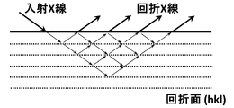
- a steel plate sample is irradiated with an X-ray beam so as to satisfy Bragg's diffraction conditions, and the diffracted X-ray beam is exposed to a detector (CCD camera) to obtain mapping data of diffracted X-ray intensity.
- the diffracted X-ray intensity is converted into color density, and the X-ray scan area is displayed as a color density distribution image.
- an X-ray topography image is obtained.
- the rocking curve measurement may adjust the measurement position where the intensity can be maximized.
- the horizontal axis is the X-ray incident angle ⁇ s (°)
- the vertical axis is the diffracted X-ray intensity.
- TEM transmission electron microscope
- FIG. 2 shows an example of an X-ray topography image.
- a sample of 50 mm in the width direction (TD direction) and 150 mm in the rolling direction (RD direction) is taken from the grain-oriented electrical steel sheet, and the surface of this sample is irradiated with an X-ray beam (Cu K ⁇ ray). is irradiated to the desired diffraction surface (hkl) so as to satisfy the Bragg diffraction condition, and the intensity of the reflected diffraction X-ray at that time is measured with a high-resolution CCD camera or the like to create a mapping image of the diffraction X-ray intensity. (See Figure 1).
- a still image of the diffraction image is taken while the sample is stationary without performing TDI (Time Delay Integration) scanning (Snap Shot).
- TDI Time Delay Integration
- Each pixel of the CCD camera is exposed to the diffracted X-rays from each position on the sample and charge is accumulated. Mapping data of the diffracted X-ray intensity is created by scanning the sample and reading out the exposure charge at each position. be.
- the diffraction surface (310) condition is adopted as the measurement condition unless otherwise specified. From this mapping image, a plurality of lines extending at approximately equal intervals in the direction where the angle ⁇ made with the rolling direction of the steel plate is 60 to 120 °, and the average value of the X-ray diffraction intensity of the entire mapping data A portion with low intensity (a portion that looks white due to low color density) is determined to be linear distortion introduced by the energy beam.
- the width of the linear distortion and the half width of the peak of the X-ray topography spectrum are obtained by the following method. That is, in the linear distortion on the X-ray topography image obtained by the above method, the position where the intensity is the lowest is defined as the central position of the distortion. A range of 1.50 mm in the rolling direction centered on the strain (a range of ⁇ 0.75 mm in the rolling direction centered on the linear strain) is applied to the straight line connecting the desired two points. Obtain density data (pixel values). As shown in FIG. 3, by plotting the measurement position on the horizontal axis and the pixel value on the vertical axis, a distribution curve (line profile) of the reflected diffraction X-ray intensity is obtained.
- the maximum value of the reflection intensity is I max
- the background intensity is I 0
- /2 is defined as the half width. From the viewpoint of noise removal of the spectrum, the same position may be measured several times and the sum may be used.
- the X-ray topography spectrum may be approximated as a continuous curve by a fitting process.
- a linear strain is defined as a continuous curved range including the center position of the strain and having a reflection intensity smaller than I0 .
- Iz be the reflection intensity in the linear strain region.
- the diffraction X-ray intensity increases as the crystal lattice strain increases, weakens as the strain decreases, and reaches a constant value when the strain is zero (extinction effect).
- the traveling wave in the X-ray incident direction and the diffracted wave scattered on the diffraction plane undergo multiple interference (multiple scattering), and then the propagating wave in the diffraction direction becomes reflected diffracted X-rays. emerges from the crystal surface as (kinetic diffraction).
- the diffracted X-ray intensity is stronger in kinetic diffraction than in dynamic diffraction (extinction effect).
- the spectral intensity is strong at a location where a large amount of strain is locally introduced due to kinetic diffraction (for example, the maximum value is I max ).
- the spectral intensity becomes a constant value (for example, Io ) due to the attenuation effect.
- the spectral intensity is weak (for example, the minimum value is Imin ).
- the plurality of linear strains on the surface of the base steel sheet have a deviation angle of 30° or less from the direction perpendicular to the rolling direction. .
- the plurality of linear strains extend continuously or intermittently in a direction forming an angle ⁇ of 60 to 120° with respect to the rolling direction. If the angle is out of this range, the effect of refining the 180° magnetic domain of the steel sheet is reduced, and a sufficient iron loss reduction effect cannot be obtained.
- the interval in the rolling direction between a plurality of adjacent linear residual strains is set to 3.0 to 9.0 mm.
- the interval in the rolling direction is set to 3.0 mm or more. It is preferable that the plurality of linear residual strains are substantially parallel and the intervals between them are substantially equal.
- the length of the residual strain in the sheet width direction is not limited, it is preferably formed from one end to the other end in the width direction of the base steel plate.
- the major axis (length along the width direction) d0 of the energy beam irradiation part it is preferable that the length d1 along the width direction of the energy ray non-irradiated section sandwiched between the two energy ray irradiation sections satisfies d1 ⁇ 3 ⁇ d0.
- d0 may be in the range of 50 ⁇ m or more and 50 mm or less.
- the distance between adjacent linear thermal strains is determined using X-ray topography under the conditions described above. can be measured by specifying
- an X-ray beam is further irradiated in a range of 3.0 mm in the rolling direction centering on the linear strain on the surface, and the X-ray reflection intensity of the (310) plane is , the minimum value is I min and the background intensity is I 0 , and an X-ray beam is irradiated in a range of 3.0 mm in the rolling direction centering on the linear strain on the back surface, and the obtained diffraction surface (310)
- the minimum value of the X-ray reflection intensity of the surface is J min and the background intensity is J 0
- I min , I 0 , J min , and J 0 may satisfy the following formula (2). preferable.
- the X-ray reflection intensity of the diffraction surface (310) in the range of 3.0 mm ( ⁇ 1.5 mm) in the rolling direction centered on the linear strain on the front and back surfaces is obtained by the following method. That is, for the surface, an X-ray topography image (strain distribution image) is obtained under the conditions described above. On the obtained image, one distorted point is selected, and a straight line parallel to the rolling direction (RD direction) connects point A at +0.075 mm and point B at ⁇ 0.075 mm. Color density data (pixel values) are obtained on the straight line connecting AB.
- a glass coating is formed on the surface of the base steel sheet.
- the glass coating may be formed only on one side of the base steel sheet, but is preferably formed on both sides.
- a glass coating is an inorganic coating containing magnesium silicate as a main component.
- the glass coating is formed by reaction between the annealing separator containing magnesia (MgO) applied to the surface of the base steel plate and the components on the surface of the base steel plate in the final annealing. (more specifically, a composition containing Mg 2 SiO 4 as a main component) derived from the components of
- MgO magnesia
- a tension applying insulating coating is formed on the surface of the glass coating.
- the tension-applying insulating coating may be formed only on one side, but is preferably formed on both sides.
- the tension-imparting insulating coating provides electrical insulation to the grain-oriented electrical steel sheet, thereby reducing eddy current loss and improving iron loss of the grain-oriented electrical steel sheet.
- the tension-imparting insulating coating provides various properties such as corrosion resistance, heat resistance, and slipperiness.
- the tension-applying insulating coating has the function of applying tension to the grain-oriented electrical steel sheet.
- the tension-applying insulating coating may be a known coating formed by applying a coating liquid containing, for example, phosphate and colloidal silica as main components to the surface of the glass coating, followed by baking.
- the plate thickness of the base steel plate of the grain-oriented electrical steel plate according to the present embodiment is not limited, but when considering application to the core of a transformer, which requires low iron loss, low noise and low vibration, it is 0.17 to 0. It is preferably 0.30 mm. The thinner the plate thickness, the more effectively the eddy current loss is reduced, and the better the iron loss. Special equipment is required to manufacture a base material steel plate of less than 0.17 mm, which is not preferable in terms of production, such as an increase in manufacturing costs. Therefore, industrially preferable plate thickness is 0.17 mm or more. More preferably, it is 0.18 mm or more.
- the grain-oriented electrical steel sheet according to this embodiment can be manufactured by a manufacturing method including the following steps. (i) in mass %, C: 0.010 to 0.200%, Si: 3.00 to 4.00%, Mn: 0.01 to 0.50%, N: 0.020% or less, Sol.
- each step can be performed by appropriately applying known conditions.
- ⁇ Hot rolling process> In the hot rolling process, for example, in mass%, C: 0.010 to 0.200%, Si: 3.00 to 4.00%, Mn: 0.01 to 0.50%, N: 0.020% Below, Sol. Al: 0.010 to 0.040%, P: 0.030% or less, S: 0.005 to 0.040%, Sn: 0 to 0.50%, Cu: 0 to 0.50%, Bi: 0 to 0.020%, Cr: 0 to 0.50%, Se: 0 to 0.020%, Sb: 0 to 0.500%, Mo: 0 to 0.10%, the balance being Fe and A billet such as a slab having a chemical composition containing impurities is heated and then hot-rolled to obtain a hot-rolled steel sheet.
- the heating temperature of the steel billet is not particularly limited, it is preferably within the range of 1100 to 1450.degree.
- the heating temperature is more preferably 1300-1400°C.
- the hot rolling conditions are not particularly limited, and may be appropriately set based on the required properties.
- the thickness of the hot-rolled steel sheet obtained by hot rolling is preferably, for example, within the range of 2.0 mm or more and 3.0 mm or less. The reason why the chemical composition of the steel slab is set within the above range is to obtain the chemical composition of the base material steel sheet described above in consideration of the manufacturing process described below.
- the hot-rolled sheet annealing process is a process of annealing the hot-rolled steel sheet manufactured through the hot rolling process. By performing such an annealing treatment, recrystallization occurs in the steel sheet structure, making it possible to achieve good magnetic properties.
- the hot-rolled steel sheet manufactured through the hot rolling process may be annealed according to a known method.
- the means for heating the hot-rolled steel sheet during annealing is not particularly limited, and a known heating method can be employed.
- the annealing conditions are also not particularly limited, but for example, the hot-rolled steel sheet can be annealed in a temperature range of 900 to 1200° C. for 10 seconds to 5 minutes.
- the hot-rolled steel plate after the hot-rolled plate annealing step is cold-rolled including a plurality of passes to obtain a cold-rolled steel plate having a thickness of 0.17 to 0.30 mm.
- the cold rolling may be a single cold rolling (a series of cold rolling without intervening intermediate anneals), where the cold rolling is interrupted and at least one or more intermediate anneals are performed before the final pass of the cold rolling process. Then, cold rolling may be performed multiple times with intermediate annealing. When performing intermediate annealing, it is preferable to hold the temperature at 1000 to 1200° C. for 5 to 180 seconds.
- the annealing atmosphere is not particularly limited. Considering the manufacturing cost, the number of times of intermediate annealing is preferably 3 times or less.
- the surface of the hot-rolled steel sheet may be pickled under known conditions.
- a hot-rolled steel sheet may be cold-rolled according to a known method to obtain a cold-rolled steel sheet.
- the final rolling reduction can be in the range of 80% or more and 95% or less. If the final rolling reduction is less than 80%, there is a high possibility that Goss nuclei with a high degree of accumulation of the ⁇ 110 ⁇ 001> orientation in the rolling direction cannot be obtained, which is undesirable. On the other hand, if the final rolling reduction exceeds 95%, secondary recrystallization is likely to become unstable in the subsequent finish annealing step, which is not preferable.
- the final rolling reduction is the cumulative rolling reduction of cold rolling, and when intermediate annealing is performed, the cumulative rolling reduction of cold rolling after final intermediate annealing.
- ⁇ Decarburization annealing process> the obtained cold-rolled steel sheet is subjected to decarburization annealing.
- decarburization annealing the cold-rolled steel sheet is primarily recrystallized, and C, which adversely affects magnetic properties, is removed from the steel sheet.
- Goss nuclei are increased and the secondary recrystallized grains obtained during finish annealing, which will be described later, are refined. Considering that the grain boundaries themselves function as magnetic poles (sites for generating leakage magnetic flux), the magnetostatic energy of the entire system increases due to the refinement of the secondary recrystallized grains.
- the heating rate in the temperature range of 550 to 750° C. (first temperature range) is increased during heating for decarburization annealing. and shorten the residence time in the temperature range. Specifically, when the heating rate in the first temperature range is less than 500° C./second, the increase in Goss nuclei becomes insufficient. Therefore, the heating rate in the temperature range of 550 to 750° C. is set to 500° C./second or more.
- the temperature increase rate there is no upper limit to the temperature increase rate, but if the temperature increase rate exceeds 2000° C./sec, there is a concern that the load on the apparatus will become too high. Therefore, the heating rate in the temperature range of 550 to 750° C. may be 2000° C./sec or less. Decarburization annealing under such conditions causes the sharpness of the crystal orientation after secondary recrystallization to approach the ideal Goss orientation. That is, a secondary recrystallized structure with a relatively small crystal orientation dispersion can be obtained. By applying strain to such a structure under the conditions described later, it is possible to achieve both low iron loss and low noise.
- the oxide film formed on the surface of the steel sheet in this temperature range is mostly SiO 2 . This is because SiO 2 has the highest rate of formation compared to other oxide films. Since SiO 2 has an effect of suppressing decarburization, it is preferable from the viewpoint of promoting decarburization that the amount of SiO 2 formed in the film is not excessive.
- the temperature range of 750 to 800°C (second temperature range ), or by increasing the temperature rise rate in the temperature range of 750 to 800 ° C. and controlling the dew point atmosphere, the SiO 2 formed in the temperature range of 550 to 750 ° C. is thickened. can be avoided.
- the temperature increase rate in the temperature range of 750 to 800° C. is set to 800° C./second or more.
- the heating rate in the temperature range of 750 to 800°C is preferably 1000°C/second or more. There is no upper limit to the temperature increase rate, but if the temperature increase rate exceeds 2000° C./sec, there is a concern that the load on the apparatus will become too high. Therefore, the heating rate in the temperature range of 750 to 800° C. may be 2000° C./sec or less.
- the atmospheric dew point was set to ⁇ 50 to 20 ° C.
- the temperature rise rate is set to 50° C./second or more. If the atmospheric dew point exceeds 20° C. or the heating rate is less than 50° C./second, the growth of SiO 2 cannot be sufficiently suppressed. On the other hand, the lower the atmospheric dew point, the better. Therefore, although the lower limit is not set, special equipment is required to achieve a temperature of less than -50°C, which is not industrially preferable. Therefore, the lower limit of the atmospheric dew point may be -50°C.
- the atmosphere in the first temperature range is not particularly limited, and known conditions can be applied.
- a nitriding treatment may be performed between the decarburization annealing step and the finish annealing step described later.
- the cold-rolled steel sheet after the decarburization annealing process is maintained at about 700 to 850° C. in a nitriding atmosphere (an atmosphere containing gas having nitriding ability such as hydrogen, nitrogen, and ammonia).
- a nitriding atmosphere an atmosphere containing gas having nitriding ability such as hydrogen, nitrogen, and ammonia.
- the steel sheet is preferably subjected to nitriding treatment so that the N content of the cold-rolled steel sheet is 40 to 1000 ppm on a mass basis.
- the N content in the cold-rolled steel sheet after nitriding treatment is less than 40 ppm, AlN may not precipitate sufficiently in the cold-rolled steel sheet, and AlN may not function as an inhibitor. Therefore, when using AlN as an inhibitor, the N content in the cold-rolled steel sheet after nitriding treatment is preferably 40 ppm or more. On the other hand, when the N content of the cold-rolled steel sheet exceeds 1000 ppm, excessive AlN is present in the steel sheet even after secondary recrystallization is completed in finish annealing. Such AlN causes iron loss deterioration. Therefore, the N content in the cold-rolled steel sheet after nitriding treatment is preferably 1000 ppm or less.
- finish annealing step a predetermined annealing separator is applied to one or both surfaces of the cold-rolled steel sheet obtained in the decarburization annealing step or further nitrided, and then finish annealing is performed. Finish annealing is generally performed for a long time while the steel sheet is coiled. Therefore, prior to finish annealing, an annealing separating agent is applied to the cold-rolled steel sheet for the purpose of preventing seizure between the inside and outside of the winding of the coil, and dried.
- an annealing separator containing MgO as a main component for example, containing 80% or more in weight fraction
- a glass coating can be formed on the surface of the base steel sheet by using the annealing separator containing MgO as a main component. If MgO is not the main component, no primary coating (glass coating) is formed. This is because the primary coating is a Mg 2 SiO 4 or MgAl 2 O 4 compound and lacks Mg necessary for the formation reaction.
- Finish annealing may be carried out, for example, in an atmospheric gas containing hydrogen and nitrogen, under the conditions of raising the temperature to 1150 to 1250° C. and annealing in that temperature range for 10 to 60 hours.
- a tension-imparting insulating coating is formed on one side or both sides of the cold-rolled steel sheet after final annealing.
- the conditions for forming the tension-applying insulating coating are not particularly limited, and a known insulating coating treatment liquid may be used and applied and dried by a known method.
- the surface of the steel sheet on which the insulating coating (tension-imparting insulating coating) is to be formed is subject to optional pretreatment such as degreasing with alkali, or pickling with hydrochloric acid, sulfuric acid, phosphoric acid, etc. It may be the surface that has been subjected to the pretreatment, or the surface that has not been subjected to these pretreatments after the final annealing.
- the insulating coating formed on the surface of the steel sheet is not particularly limited as long as it is used as an insulating coating for grain-oriented electrical steel sheets, and known insulating coatings can be used. Examples of such insulating coatings include coatings containing phosphate and colloidal silica as main components.
- a composite insulation film containing an inorganic substance as a main component and an organic substance can be used.
- the composite insulating coating is mainly composed of, for example, at least one of inorganic substances such as metal chromate, metal phosphate, colloidal silica, Zr compound, Ti compound, etc., and fine organic resin particles are dispersed. It is an insulating film that has In particular, from the viewpoint of reducing the environmental load during production, which has been in increasing demand in recent years, insulating coatings using metal phosphates, Zr or Ti coupling agents, or their carbonates or ammonium salts as starting materials. Sometimes used.
- ⁇ Magnetic domain refining process In the magnetic domain refining process, energy beams such as laser beams and electron beams are applied to the surface of the tension-imparting insulating coating to form an angle near the surface of the base steel sheet (from the surface to the inside of the steel sheet) with respect to the rolling direction. Introduce a plurality of linear strains extending in directions with ⁇ between 60 and 120°. In the magnetic domain refining step, a plurality of linear strains (thermal strain caused by rapid heating by energy beam irradiation and subsequent rapid cooling) are formed at predetermined intervals in the rolling direction. (p)) is 3.0 to 9.0 mm in the rolling direction.
- Energy rays include laser beams and electron beams.
- the laser beam may be a continuous wave laser or a pulsed laser.
- Types of laser beams can include, for example, fiber lasers, YAG lasers, or CO2 lasers.
- the electron beam may be a continuous beam or an intermittent beam.
- Irradiate the beam 250 ⁇ Ip ⁇ 2000 Formula (3) 0.005 ⁇ Up ⁇ 0.050 Formula (4) If Ip is less than 250, sufficient energy is not supplied, and the magnetic domain refining effect (iron loss improvement effect) cannot be obtained. Therefore, Ip is 250 or more. Ip is preferably 500 or more. On the other hand, when Ip exceeds 2000, the noise characteristic deteriorates due to excessive thermal strain introduced beyond the domain refining effect. Therefore, Ip is 2000 or less. Ip is preferably 1750 or less, more preferably 1500 or less. On the other hand, when Up is 0.005 or less, a sufficient irradiation effect cannot be obtained and iron loss cannot be sufficiently improved. Therefore, Up is greater than 0.005. On the other hand, when Up exceeds 0.050, noise characteristics deteriorate. Therefore, Up is 0.050 or less. Although a laser beam has been described as a specific example here, the same applies to the case of using other energy beam means such as an electron beam.
- the beam aspect ratio defined by (dl/dc) is controlled so as to satisfy the following equation (5). 0.001 ⁇ dl/dc ⁇ 1.000 (5)
- the beam aspect ratio is 0.001 or less, heat removal occurs due to beam irradiation, the input efficiency of input energy decreases, and a sufficient magnetic domain refining effect (iron loss improvement effect) cannot be obtained. Therefore, the beam aspect ratio is greater than 0.001.
- the beam aspect ratio is 1.000 or more, heat removal due to beam irradiation does not occur, but instead residual stress is generated, and the noise reduction effect cannot be obtained. Therefore, the beam aspect ratio is less than 1.000.
- the beam aspect ratio is preferably less than 0.050, more preferably less than 0.005.
- the diameter dl of the energy ray in the direction perpendicular to the beam scanning direction in units of ⁇ m should satisfy the following formula (6). 10 ⁇ dl ⁇ 200 (6) It is industrially difficult to produce a beam with dl of less than 10. Therefore, dl is 10 or more. On the other hand, when dl is 200 or more, excessive thermal strain is introduced beyond the magnetic domain refining effect, resulting in deterioration of noise characteristics. Therefore, dl is less than 200. dl is preferably less than 150, more preferably less than 100.
- steel slabs with different chemical compositions were prepared for each steel number (A to G).
- grain-oriented electrical steel sheets (Test Nos. 1 to 28) were manufactured using each steel piece. Specifically, after heating the steels B, E, and F to a temperature within the range of 1100 to 1200° C., the steels are hot-rolled to obtain hot-rolled steel sheets having a thickness of 2.3 ⁇ 0.3 mm. was made. In addition, after heating the billets A, C, D, and G to a temperature within the range of 1300 to 1400° C., the billets are hot-rolled to obtain a hot-rolled steel sheet having a thickness of 2.3 ⁇ 0.3 mm. was made.
- the obtained hot-rolled steel sheet was subjected to hot-rolled sheet annealing.
- the hot-rolled steel sheet was annealed under conditions of an annealing temperature of 1000 to 1200° C. and a holding time of 10 to 200 seconds.
- the hot-rolled steel sheet after hot-rolling and annealing is subjected to pickling or the like to remove surface scales, and then cold rolling is performed once or twice with annealing intervening, so that the thickness of the base material is 0.19 to 0.19.
- a 0.23 mm cold-rolled steel sheet was produced.
- the obtained cold-rolled steel sheets were subjected to decarburization annealing under the conditions shown in Table 2.
- the soaking step of the decarburization annealing was performed at a temperature of 800 to 840° C. for 100 to 150 seconds.
- the degree of oxidation (PH 2 O/PH 2 ) at that time was controlled to 0.3 to 0.5.
- Test no. with steels B, E, F; 2, 5, 6, 9, 10, 14, 16, 18, 23, 26, and 27 were further nitrided.
- the cold-rolled steel sheet was subjected to a finish annealing process. Specifically, an annealing separator containing magnesium oxide (MgO) as a main component (80% or more in weight fraction) was applied to the surface of the cold-rolled steel sheet.
- MgO magnesium oxide
- the cold-rolled steel sheet coated with the annealing separator was annealed at 1000 to 1300° C. to produce a steel sheet having a glass coating on the base steel sheet. Then, a coating forming step was performed on this steel plate. Specifically, the surface of the steel plate (more specifically, the surface of the glass coating, which is the primary coating) was coated with an insulating coating-forming liquid mainly composed of colloidal silica and phosphate, and heat-treated (baked). As a result, a grain-oriented electrical steel sheet comprising a base steel plate, a glass coating formed on the base steel plate, and a tension-imparting insulating coating formed on the glass coating was obtained.
- each test No. before magnetic domain refining obtained in the manner described above.
- the chemical composition of the base material steel sheet of the grain-oriented electrical steel sheet was obtained by the following method. First, each test no. was removed from the grain-oriented electrical steel sheet. Specifically, the grain-oriented electrical steel sheet was immersed in a sodium hydroxide aqueous solution containing 30 to 50% by mass of NaOH and 50 to 70% by mass of H 2 O at 80 to 90° C. for 7 to 10 minutes. After the immersion, the grain-oriented electrical steel sheet (the grain-oriented electrical steel sheet from which the tensile insulating coating was removed) was washed with water.
- the glass coating was removed from the grain-oriented electrical steel sheet that did not have the tension-imparting insulating coating. Specifically, the grain-oriented electrical steel sheet was immersed in a hydrochloric acid aqueous solution containing 30 to 40% by mass of HCl at 80 to 90° C. for 1 to 10 minutes. As a result, the glass coating was removed from the base steel plate. The base material steel plate after immersion was washed with water. After washing with water, it was dried with a warm air blower for a little less than 1 minute. Through the above steps, the base material steel sheet was taken out from the grain-oriented electrical steel sheet.
- the chemical composition of the taken-out base material steel plate was determined by a known component analysis method. Specifically, a drill was used to generate chips from the base steel plate, and the chips were collected. The collected chips were dissolved in acid to obtain a solution. ICP-AES was performed on the solution to perform elemental analysis of chemical composition. Si in the chemical composition of the base steel sheet was obtained by the method (silicon quantification method) specified in JIS G 1212 (1997). Specifically, when the above chips were dissolved in acid, silicon oxide precipitated as a precipitate. This precipitate (silicon oxide) was filtered with a filter paper, and the mass was measured to determine the Si content.
- the C content and S content were determined by a well-known high-frequency combustion method (combustion-infrared absorption method). Specifically, the above solution was combusted by high-frequency heating in an oxygen stream, the generated carbon dioxide and sulfur dioxide were detected, and the C content and S content were determined.
- the N content was determined using the well-known inert gas fusion-thermal conductivity method.
- the chemical composition of the base material steel plate was obtained by the above analysis method. Table 3 shows the results.
- each test No. The grain-oriented electrical steel sheet was evaluated for iron loss before magnetic domain refining.
- Each test no. A sample having a width of 60 mm and a length of 300 mm, including the central position of the plate width, was taken from the grain-oriented electrical steel sheet. The length direction of the sample was parallel to the rolling direction. The collected samples were held in a nitrogen atmosphere with a dew point of 0° C. or less at 800° C. for 2 hours to remove the strain introduced at the time of sample collection. Using this sample, iron loss W 17/50 (W/kg) was measured at a frequency of 50 Hz and a maximum magnetic flux density of 1.7 T.
- each test No. was subjected to magnetic domain refining by irradiating the surface of the grain-oriented electrical steel sheet with energy rays under the conditions shown in Tables 4 and 5 using a continuous wave laser or an intermittent wave laser. Evaluation tests of noise characteristics and magnetic characteristics were performed on grain-oriented electrical steel sheets after magnetic domain refining.
- Magnetostriction was measured by an AC magnetostriction measurement method using a magnetostriction measurement device on the sample of width 60 mm ⁇ length 300 mm subjected to the magnetic domain control.
- the magnetostriction measuring device was provided with a laser Doppler vibrometer, an excitation coil, an excitation power supply, a magnetic flux detection coil, an amplifier, and an oscilloscope. Specifically, an alternating magnetic field was applied to the sample so that the maximum magnetic flux density in the rolling direction was 1.7 T. The change in length of the sample due to expansion and contraction of the magnetic domain was measured with a laser Doppler vibrometer to obtain the magnetostriction signal.
- the values shown in Table 2 of JIS C 1509-1 (2005) were used. Based on the obtained magnetostriction velocity level (LVA), noise characteristics were evaluated according to the following criteria. If the magnetostriction rate level was less than 60 dBA, it was judged to be "excellent in noise characteristics”. It was judged to be particularly excellent if it was less than 50 dBA. The magnetostriction rate level was 60 dBA or higher, and the "insufficient noise characteristics" were determined. Table 5 shows the results.
- iron loss improvement rate was evaluated in order to evaluate the effect of iron loss improvement by magnetic domain control.
- Iron loss W 17/50 (W/kg) was measured at a frequency of 50 Hz and a maximum magnetic flux density of 1.7 T using a 60 mm wide ⁇ 300 mm long sample subjected to magnetic domain control. Then, using the iron loss W 17/50 (W/kg) measured here and the iron loss W 17/50 (W/kg) measured before magnetic domain control, the iron loss improvement rate (%) is calculated as [(magnetic domain Iron loss before control-iron loss after magnetic domain control) ⁇ 100]/iron loss before magnetic domain control.
- the magnetic flux density (T) was determined by a single plate magnetic property test (SST test). Specifically, a magnetic field of 800 A/m was applied to the sample to obtain the magnetic flux density (T). Table 5 shows the results.
- test no. 1 to 12 and 21 and 24 to 28 are excellent in magnetic properties and noise properties. That is, "iron loss improvement rate is 5% or more", “iron loss after magnetic domain control is 0.85 W/kg or less”, and “magnetostriction rate level is less than 60 dBA”.
- Ip and Up which are the laser irradiation conditions, were within a more preferable control range.
- Test No. Nos. 13 to 20, 22, and 23 are comparative examples, and were inferior in at least one of magnetic properties and noise properties.
- Test no. No. 14 was not sufficiently decarburized. Therefore, the iron loss exceeded 0.85 W/kg even after magnetic domain control, and the iron loss improvement rate was also low. Test no.
- Test no. 16 had linear strain intervals of less than 3.0 mm. Due to the excessive strain introduced, the noise characteristics were inferior. Test no. In Nos. 17 to 20, the strain imparting conditions were outside the scope of the present invention. Test no. Test No. 17 has a small Ip. In No.
- Test no. 20 the magnetic domain refining effect was not obtained because Up was small, the half width of the X-ray topography spectrum was outside the range of the present invention, and the iron loss improvement rate did not reach 5%.
- Test no. 18 has a large Ip. Since No. 19 had a large Up, the half width of the X-ray topography spectrum was outside the range of the present invention, and the noise characteristics were poor.
Landscapes
- Chemical & Material Sciences (AREA)
- Engineering & Computer Science (AREA)
- Materials Engineering (AREA)
- Mechanical Engineering (AREA)
- Metallurgy (AREA)
- Organic Chemistry (AREA)
- Physics & Mathematics (AREA)
- Crystallography & Structural Chemistry (AREA)
- Thermal Sciences (AREA)
- Electromagnetism (AREA)
- Manufacturing & Machinery (AREA)
- Dispersion Chemistry (AREA)
- Power Engineering (AREA)
- Optics & Photonics (AREA)
- Chemical Kinetics & Catalysis (AREA)
- General Chemical & Material Sciences (AREA)
- Manufacturing Of Steel Electrode Plates (AREA)
Abstract
Description
本願は、2021年03月26日に、日本に出願された特願2021-053618号に基づき優先権を主張し、その内容をここに援用する。
鉄損とは、鉄心を交流磁場で励磁した場合に、熱エネルギとして消費される電力損失であり、省エネルギの観点から、鉄損はできるだけ低いことが求められる。鉄損の高低には、磁化率、板厚、被膜張力、不純物量、電気抵抗率、結晶粒径、磁区サイズなどが影響する。方向性電磁鋼板に関し、様々な技術が開発されている現在においても、エネルギ効率を高めるため、鉄損を低減する研究開発が継続されている。
特許文献1では、容易に、かつ高い生産性を確保しながら、方向性電磁鋼板のL方向及びC方向の両方向における鉄損を低減することができることが示されている。
特許文献2では、レーザが、ビーム伝搬方向に垂直な断面内のレーザ光強度分布が光軸中心近傍に最大強度を持つTEM00モードであり、照射ビームの圧延方向集光径d[mm]、レーザビームの走査線速度V[mm/s]、レーザの平均出力P[W]が、0<d≦0.2、0.001≦P/V≦0.012の範囲であることで、鉄損の低減された方向性電磁鋼板が得られることが示されている。
特許文献3では、レーザがパルス発振QスイッチCO2レーザであり、照射ビーム形状が板幅方向に長軸を持つ楕円である。また、レーザパルスの照射パワー密度を鋼板表面の皮膜損傷閾値以下に設定することで、レーザ照射痕の発生を抑制し、且つ楕円ビームの長軸長を板幅方向のパルスビーム照射間隔以上に設定することで、連続するパルスビームを鋼板表面で重畳させ、磁気特性改善に必要十分な積算照射エネルギを与え、レーザ照射痕を抑制することで、効率的な磁区制御効果が得られることが示されている。
特許文献4では、鋼板表面における圧延方向の幅が周期的に変化した還流磁区領域が形成され、各々の前記還流磁区領域が、鋼板表面における圧延方向の最大幅Wmaxの最小幅Wminに対する比(Wmax/Wmin)が1.2以上2.2以下、鋼板表面における圧延方向の平均幅Waveが80μm以上250μm以下、板厚方向の最大深さDが32μm以上、(Wave×D)/sが0.0007mm以上0.0016mm以下の条件を満たすことによって、従来よりも良好な鉄損・騒音バランスが実現できることが示されている。
特許文献5では、hw/sで表される歪み導入量指標が鉄損及び騒音に影響することが示唆されている。
また、特許文献8には、電子ビームの特徴を生かした鉄損低減に有利な還流磁区形状を形成することによって、幅広い板厚範囲において低鉄損化した方向性電磁鋼板が得られることが示されている。
また、特許文献9には、鋼板面内の圧延方向に対し、60°から120°の方向に、LaB6から放出された電子ビームによって形成された線状歪みを有する鉄心用方向性電磁鋼板が開示されている。
また、特許文献10には、ビーム照射域に占めるビーム照射痕の面積比率を制御した、絶縁性並びに耐食性に優れる方向性電磁鋼板及びその製造方法が開示されている。
しかしながら、特許文献6~10は、いずれも鉄損の低減のために還流磁区を制御しているか、または還流磁区制御に付随して発生する被膜特性を改善するための技術であり、低騒音を実現するための還流磁区制御については検討されていなかった。そのため、特許文献6~10の技術では、騒音特性の改善が、近年求められるより優れた鉄損・騒音バランスに対しては十分でないことが分かった。
本発明は、鉄損特性、特に磁区制御前後における鉄損改善率と、騒音特性とに優れる、方向性電磁鋼板及びその製造方法を提供することを課題とする。
本発明者らは、レーザビームまたは電子ビーム等の照射条件と、鉄損特性及び騒音特性との関係について検討を行った。その結果、レーザビームまたは電子ビーム等の投入エネルギを小さくすることで、騒音特性が改善されるが、この場合、磁区制御が十分でなく、鉄損特性の改善は十分ではないことが分かった。
そこで、本発明者らは、騒音特性を劣化させずに鉄損特性を改善する方法について、さらに検討を行った。その結果、製造過程において、レーザビームまたは電子ビーム等の照射条件、及び脱炭焼鈍条件を制御することで、レーザビームまたは電子ビーム等の投入エネルギが小さい場合でも、十分な磁区細分化が達成でき、レーザビームまたは電子ビーム等の照射後に低鉄損と低騒音とを両立できることを見出した。
[1]本発明の一態様に係る方向性電磁鋼板は、母材鋼板と、前記母材鋼板上に形成されているグラス被膜と、前記グラス被膜上に形成されている張力付与絶縁被膜と、を備え、前記母材鋼板は、質量%で、C:0.010%以下、Si:3.00~4.00%、Mn:0.01~0.50%、N:0.010%以下、Sol.Al:0.020%以下、P:0.030%以下、S:0.010%以下、Sn:0~0.50%、Cu:0~0.50%、Cr:0~0.50%、Se:0~0.020%、Sb:0~0.500%、Mo:0~0.10%、残部:Fe及び不純物、からなる化学組成を有し、前記母材鋼板の表面には、圧延方向に対して交差する方向に連続的にまたは断続的に延在する、複数の線状の歪が存在し、互いに隣り合う前記複数の線状の歪の、前記圧延方向における間隔pが3.0~9.0mmであり、前記線状の歪の幅が、10~250μmであり、表面のX線トポグラフィ画像から得られる、前記線状の歪を中心とする前記圧延方向に1.50mmの範囲におけるX線トポグラフィスペクトルにおいて、スペクトル強度の最大値を含む前記X線トポグラフィスペクトルのピークの半値幅が、0.02mm以上、0.10mm以下である。
[2][1]に記載の方向性電磁鋼板は、前記表面の前記線状の歪を中心とする前記圧延方向に3.0mmの範囲にX線ビームを照射し、(310)面のX線反射強度の、最小値をImin、バックグラウンド強度をI0とし、裏面の前記線状の歪を中心とする前記圧延方向に3.0mmの範囲にX線ビームを照射し、得られた回折面(310)面のX線反射強度の、最小値をJmin、バックグラウンド強度をJ0としたとき、前記Imin、前記I0、前記Jmin、前記J0が下記式(2)を満足してもよい。
0.02 ≦ |J0-Jmin|/|I0-Imin| ≦ 1.00 (2)
[3][1]または[2]に記載の方向性電磁鋼板は、前記母材鋼板の前記化学組成が、Sn:0.01~0.50%、Cu:0.05~0.50%、のいずれかまたは両方を含んでもよい。
[4]本発明の別の態様に係る方向性電磁鋼板の製造方法は、[1]または[2]に記載の方向性電磁鋼板の製造方法であって、質量%で、C:0.010~0.200%、Si:3.00~4.00%、Mn:0.01~0.50%、N:0.020%以下、Sol.Al:0.010~0.040%、P:0.030%以下、S:0.005~0.040%、Sn:0~0.50%、Cu:0~0.50%、Bi:0~0.020%、Cr:0~0.50%、Se:0~0.020%、Sb:0~0.500%、Mo:0~0.10%、残部:Fe及び不純物、からなる化学組成を有する鋼片を加熱した後に熱間圧延し、熱延鋼板を得る、熱間圧延工程と、前記熱延鋼板に熱延板焼鈍を施す、熱延板焼鈍工程と、前記熱延板焼鈍工程後の前記熱延鋼板に、一回又は中間焼鈍を挟む複数回の冷間圧延を行って冷延鋼板を得る、冷間圧延工程と、前記冷延鋼板に脱炭焼鈍を施す、脱炭焼鈍工程と、母材鋼板である前記脱炭焼鈍工程後の前記冷延鋼板の表裏面に、MgOを主成分とする焼鈍分離剤を塗布し、乾燥させた後、仕上げ焼鈍を施すことでグラス被膜を形成する、仕上げ焼鈍工程と、前記グラス被膜上に張力付与絶縁被膜を形成し、前記母材鋼板と前記母材鋼板上に形成されているグラス被膜と前記グラス被膜上に形成されている張力付与絶縁被膜とを備える方向性電磁鋼板を得る、被膜形成工程と、前記方向性電磁鋼板の前記張力付与絶縁被膜の表面にエネルギ線を照射し、前記母材鋼板に複数の線状の歪を付与する、磁区細分化工程と、を有し、前記磁区細分化工程において、前記複数の線状の歪のうち、隣り合う線状の歪の圧延方向の間隔が3.0~9.0mmであり、単位Wでのエネルギ線出力Pと、単位mm2でのエネルギ線照射断面積Sを用いて、(P/S)で定義される、単位W/mm2でのエネルギ線パワー密度Ipが下記式(3)を満たし、前記エネルギ線出力Pと、単位mm/秒でのエネルギ線走査速度Vsを用いて、(P/Vs)で定義される単位J/mmのエネルギ線投入エネルギUpが、下記式(4)を満たし、かつ、前記エネルギ線の、単位μmでの、ビームスキャン方向に垂直な方向の径dlおよび前記ビームスキャン方向の径dcを用いて、(dl/dc)で定義されるビームアスペクト比、並びに、前記dlがそれぞれ下記式(5)および下記式(6)を満たし、前記脱炭焼鈍工程において、550~750℃の第1の温度域での昇温速度S1を500℃/秒以上とし、750~800℃の第2の温度域での昇温速度S2を800℃/秒以上とする、または、前記第2の温度域での前記昇温速度S2を50℃/秒以上としてかつ前記第2の温度域での雰囲気露点を-50℃~20℃とする。
250≦Ip≦2000 (3)
0.005<Up≦0.050 (4)
0.001<dl/dc<1.000 (5)
10≦dl<200 (6)
[5][4]に記載の方向性電磁鋼板の製造方法は、前記脱炭焼鈍工程と前記仕上げ焼鈍工程との間に、さらに、前記冷延鋼板に窒化処理を施す窒化処理工程を有してもよい。
[6][4]または[5]に記載の方向性電磁鋼板の製造方法は、前記鋼片の前記化学組成が、Sn:0.01~0.50%、Cu:0.05~0.50%、のいずれかまたは両方を含んでもよい。
また、母材鋼板の表面には、圧延方向と交差する方向、より具体的には圧延方向に対してなす角(φ)が60~120°である方向に、連続的にまたは断続的に延在する複数の線状の歪(熱歪)が略平行に形成されており、互いに隣り合う複数の線状の歪の、圧延方向における間隔(p)が3.0~9.0mmであり、X線トポグラフィで測定した前記複数の線状の歪のそれぞれの幅(延在方向と直交する方向の長さ)が10~250μmである。
また、本実施形態に係る方向性電磁鋼板では、表面のX線トポグラフィ画像から得られる、前記線状の歪を中心とする前記圧延方向に1.50mmの範囲(線状の歪から圧延方向に±0.75mmの範囲)におけるX線トポグラフィスペクトルにおいて、スペクトル強度の最大値を含むX線トポグラフィスペクトルのピークの半値幅が、0.02mm以上、0.10mm以下である。
(化学組成)
本実施形態に係る方向性電磁鋼板は、線状の歪の状態に大きな特徴があり、方向性電磁鋼板が備える母材鋼板は、その化学組成については限定されない。しかしながら、方向性電磁鋼板として一般に求められる特性を得るため、以下の範囲とする。本実施形態において、各元素の含有量に係る%は、断りがない限り質量%である。
C(炭素)は、製造工程における脱炭焼鈍工程の完了までの工程での、鋼板の組織制御に有効な元素である。しかしながら、C含有量が0.010%を超えると、製品板である方向性電磁鋼板の磁気特性(鉄損特性や磁束密度)が低下する。従って、本実施形態に係る方向性電磁鋼板の母材鋼板において、C含有量は、0.010%以下とする。C含有量は、好ましくは0.005%以下である。C含有量は、低ければ低いほうが好ましいが、C含有量を0.0001%未満に低減しても、組織制御の効果は飽和し、製造コストが嵩むだけとなる。従って、C含有量は、0.0001%以上としてもよい。
Si(珪素)は、方向性電磁鋼板の電気抵抗を高めて、鉄損特性を改善する元素である。Si含有量が3.00%未満では、十分な渦電流損低減効果が得られない。そのため、Si含有量は3.00%以上とする。Si含有量は、好ましくは3.20%以上、より好ましくは3.50%以上である。
一方、Si含有量が4.00%を超えると、方向性電磁鋼板が脆化し、通板性が顕著に劣化する。また、方向性電磁鋼板の加工性が低下し、圧延時に鋼板が破断しうる。このため、Si含有量は4.00%以下とする。Si含有量は、好ましくは3.80%以下、より好ましくは3.70%以下である。
スラブ等の鋼片に含有されるSiは一部、Mg2SiO4を主成分とするグラス被膜の生成に消費されることがある。そのため、出鋼時に比較して、方向性電磁鋼板では、Si含有量が減少しても良い。
Mn(マンガン)は、製造工程において、Sと結合して、MnSを形成する元素である。この析出物は、インヒビター(正常結晶粒成長の抑制剤)として機能し、鋼において、二次再結晶を発現させる。Mnは、更に、鋼の熱間加工性も高める元素である。Mn含有量が0.01%未満である場合には、上記のような効果を十分に得ることができない。そのため、Mn含有量は、0.01%以上とする。Mn含有量は、好ましくは0.02%以上、より好ましくは0.05%以上である。
一方、Mn含有量が0.50%を超えると、二次再結晶が発現せずに、鋼の磁気特性が低下する。従って、本実施形態に係る方向性電磁鋼板の母材鋼板において、Mn含有量は、0.50%以下とする。Mn含有量は、好ましくは0.20%以下、より好ましくは0.10%以下である。
N(窒素)は、製造工程において、Alと結合して、インヒビターとして機能するAlNを形成する元素である。しかしながら、N含有量が0.010%を超えると、母材鋼板中に過剰に残存するインヒビターにより、磁気特性が低下する。従って、本実施形態に係る方向性電磁鋼板の母材鋼板において、N含有量は、0.010%以下とする。N含有量は、好ましくは0.008%以下、より好ましくは0.005%以下である。
一方、N含有量の下限値は、特に規定するものではないが、0.0001%未満に低減しても、製造コストが嵩むだけとなる。従って、N含有量は、0.0001%以上としてもよい。
Sol.Al(酸可溶性アルミニウム)は、製造工程において、Nと結合して、インヒビターとして機能するAlNを形成する元素である。しかしながら、母材鋼板のSol.Al含有量が0.020%を超えると、母材鋼板中に過剰に残存するインヒビターにより、磁気特性が低下する。従って、本実施形態に係る方向性電磁鋼板の母材鋼板において、Sol.Al含有量は、0.020%以下とする。方向性電磁鋼板におけるSol.Al含有量は、なるべく低いほうが好ましい。例えば、Sol.Al含有量は、0.010%以下、または0.001%未満であり、0%でもよい。
一方、Sol.Al含有量の下限値は、特に規定するものではないが、0.0001%未満に低減しても、製造コストが嵩むだけとなる。従って、Sol.Al含有量は、0.0001%以上としてもよい。
P(リン)は、圧延における加工性を低下させる元素である。P含有量を0.030%以下とすることにより、圧延加工性が過度に低下することを抑制でき、製造時における破断を抑制することができる。このような観点から、P含有量は0.030%以下とする。P含有量は、0.020%以下であることが好ましく、0.010%以下であることがより好ましい。
P含有量は、その下限が限定されず、0%を含み得るが、化学分析の検出限界値が0.0001%であるため、実用鋼板において、実質的なP含有量の下限値は、0.0001%である。また、Pは集合組織を改善し、磁気特性を改善する効果を有する元素でもある。この効果を得るため、P含有量を0.001%以上としてもよく、0.005%以上としてもよい。
S(硫黄)は、製造工程において、Mnと結合して、インヒビターとして機能するMnSを形成する元素である。しかしながら、S含有量が0.010%を超える場合には、過剰に残存するインヒビターにより、磁気特性が低下する。従って、本実施形態に係る方向性電磁鋼板の母材鋼板において、S含有量は、0.010%以下とする。方向性電磁鋼板におけるS含有量は、なるべく低いほうが好ましい。例えば0.0001%未満であり、0%でもよい。しかしながら、方向性電磁鋼板の母材鋼板中のS含有量を0.0001%未満に低減しても、製造コストが嵩むだけとなる。従って、S含有量は、0.0001%以上であってもよい。
本実施形態に係る方向性電磁鋼板の母材鋼板の化学組成は、上述の必須元素を含有し、残部は、Fe及び不純物であってもよい。しかしながら、磁気特性等を高めることを目的として、さらに任意元素として、Sn、Cu、Cr、Se、Sb、Moを以下に示す範囲で含有してもよい。これらの元素は不純物として含有されることも許容する。
また、これら以外の元素として、例えばW、Nb、Bi、Ti、Ni、Co、Vのいずれか1種あるいは2種以上を合計で1.0%以下含有しても、本実施形態に係る方向性電磁鋼板の効果を阻害するものではない。
ここで、不純物とは、母材鋼板を工業的に製造する際に、原料としての鉱石、スクラップから、又は、製造環境などから混入するものであり、本実施形態に係る方向性電磁鋼板の作用に悪影響を及ぼさない含有量で含有することを許容される元素を意味する。
Sn(スズ)は、Goss方位を増加させる元素であり、二次再結晶粒を微細化するために有効な元素である。二次再結晶粒が小さければ、磁区細分化を行う際に、投入エネルギが小さくても十分な鉄損改善効果が得られる。上記効果を得る場合、Sn含有量を0.01%以上とすることが好ましい。Sn含有量は、より好ましくは0.02%以上、さらに好ましくは0.03%以上である。ただし、Snを含有させると、二次再結晶組織におけるGoss方位占有率が低下することが懸念される。そのため、本実施形態に係る方向性電磁鋼板の母材鋼板では、Snを含有させる場合、後述するCuと同時に含有させることが好ましい。
一方、Sn含有量が0.50%を超える場合には、二次再結晶が不安定となり、磁気特性が劣化する。そのため、含有させる場合でも、Sn含有量は0.50%以下とする。Sn含有量は、好ましくは0.30%以下であり、より好ましくは0.20%以下である。
Cu(銅)は、二次再結晶組織におけるGoss方位占有率の増加に寄与する元素である。上記効果を得る場合、Cu含有量を0.05%以上とすることが好ましい。Cu含有量は、より好ましくは0.06%以上、さらに好ましくは0.07%以上である。
一方、Cu含有量が0.50%を超える場合には、熱間圧延中に鋼板が脆化する。そのため、本実施形態に係る方向性電磁鋼板の母材鋼板では、含有させる場合でも、Cu含有量を0.50%以下とする。Cu含有量は、好ましくは0.30%以下、より好ましくは0.20%以下である。
Cr(クロム)は、磁気特性を改善する元素である。原因は明らかでないが、二次再結晶組織におけるGoss方位占有率の増加に寄与して磁気特性を向上させる等の効果があると考えられる。上記効果を得るためには、Cr含有量を、0.01%以上とすることが好ましく、0.02%以上とすることがより好ましく、0.03%以上とすることがさらに好ましい。
一方、Cr含有量が0.50%を超える場合には、Cr酸化物が形成され、磁気特性が低下する。そのため、含有させる場合でも、Cr含有量は、0.50%以下とする。Cr含有量は、好ましくは0.30%以下であり、より好ましくは0.10%以下である。
Se(セレン)は、磁気特性改善効果を有する元素である。そのため、含有させてもよい。Seを含有させる場合は、磁気特性改善効果を良好に発揮するため、Se含有量を0.001%以上とすることが好ましい。Se含有量は、より好ましくは0.003%以上であり、さらに好ましくは0.006%以上である。
一方、Se含有量が0.020%を超えると、グラス被膜の密着性が劣化する。従って、含有させる場合でも、Se含有量を0.020%以下とする。Se含有量は、好ましくは0.015%以下、より好ましくは0.010%以下である。
Sb(アンチモン)は、磁気特性改善効果を有する元素である。そのため、含有させてもよい。Sbを含有させる場合は、磁気特性改善効果を良好に発揮するため、含有量を0.005%以上とすることが好ましい。Sb含有量は、より好ましくは0.010%以上であり、さらに好ましくは0.020%以上である。
一方、Sb含有量が0.500%を超えると、グラス被膜の密着性が顕著に劣化する。従って、含有させる場合でも、Sb含有量を0.500%以下とする。Sb含有量は、好ましくは0.300%以下であり、より好ましくは0.100%以下である。
Mo(モリブデン)は、磁気特性改善効果を有する元素である。そのため、含有させてもよい。Moを含有させる場合は、磁気特性改善効果を良好に発揮するため、Mo含有量を0.01%以上とすることが好ましい。Mo含有量は、より好ましくは0.02%以上であり、さらに好ましくは0.03%以上である。
一方、Mo含有量が0.10%を超えると、冷間圧延性が劣化し、破断に至る可能性がある。従って、含有させる場合でも、Mo含有量を0.10%以下とする。Mo含有量は、好ましくは0.08%以下であり、より好ましくは0.05%以下である。
具体的には、方向性電磁鋼板を、NaOH:30~50質量%及びH2O:50~70質量%を含有する80~90℃の水酸化ナトリウム水溶液に、7~10分間浸漬することで、張力付与絶縁被膜を除去する。張力付与絶縁被膜が除去された方向性電磁鋼板を水洗し、水洗後、温風のブロアーで1分間弱、乾燥させる。乾燥後の方向性電磁鋼板(張力付与絶縁被膜を備えていない方向性電磁鋼板)を、30~40質量%のHClを含有し、80~90℃の塩酸水溶液に、1~10分間浸漬することで、グラス被膜を除去する。浸漬後の母材鋼板を水洗し、水洗後、温風のブロアーで1分間弱、乾燥させる。
以上の工程により、方向性電磁鋼板から、母材鋼板を取り出すことができる。
このような母材鋼板の化学組成は、周知の成分分析法により求める。具体的には、ドリルを用いて、母材鋼板から切粉を生成し、その切粉を採取し、採取された切粉を酸に溶解させて溶液を得る。溶液に対して、ICP-AESを実施して、化学組成の元素分析を実施する。
ここで、母材鋼板の化学組成中のSiについては、JIS G 1212(1997)に規定の方法(けい素定量方法)により求める。具体的には、上述の切粉を酸に溶解させると、酸化ケイ素が沈殿物として析出するので、この沈殿物(酸化ケイ素)をろ紙で濾し取り、質量を測定して、Si含有量を求める。
C含有量及びS含有量については、周知の高周波燃焼法(燃焼-赤外線吸収法)により求める。具体的には、上述の溶液を酸素気流中で高周波加熱により燃焼して、発生した二酸化炭素、二酸化硫黄を検出し、C含有量及びS含有量を求める。
N含有量については、周知の不活性ガス溶融-熱伝導度法を用いて求める。
本実施形態に係る方向性電磁鋼板が備える母材鋼板には、表面近傍に、レーザビームや電子ビームのようなエネルギ線の照射によって形成された残留歪である、複数の線状の歪(熱歪)が存在する。この複数の線状の歪は、それぞれが圧延方向に対してなす角φが60~120°である方向(圧延方向に対して交差する方向)に、連続的にまたは断続的に延在している。歪は、連続的に直線状に存在してもよく、断続的に一方向に(例えば点線状に)存在してもよい。
このようなエネルギ線の照射によって形成される歪(残留歪)は、特に圧延方向において圧縮歪であり、板厚方向において引張歪となり、歪部及びその板厚方向下側に、還流磁区と呼ばれる、板厚方向に磁化した領域が形成されることが知られている。還流磁区のサイズが所定の大きさ以上である場合に、180°磁区幅が細分化し、渦電流損が低減し、鉄損が低下する。一方で、還流磁区サイズが大きくなると交流で励磁した際の磁歪が大きくなって、変圧器の騒音が顕在化する。
上述したように、残留歪の形成に伴って形成される還流磁区は、180°磁区細分化のドライビングフォースであるので、低鉄損化にとって有利であるが、還流磁区によって磁歪の程度が大きくなって、変圧器に組み込んだときの騒音が大きくなる(騒音特性が劣化する)問題があった。従来は、騒音特性の劣化を抑制する場合、エネルギ線の照射ピッチを大きくしたり、エネルギ線の投入エネルギを弱めたりするなどの対策を行っていた。しかしながら、このような対応は、鉄損特性と騒音特性とがトレードオフの関係であることを前提とした、エネルギ線照射による鉄損改善効果をある程度犠牲にして騒音特性を改善する手段に過ぎなかった。
これに対し、本発明者らが検討した結果、方向性電磁鋼板において、表面からの深さが浅い(表層に局在した)還流磁区領域が形成されるような歪を導入することで、騒音特性の劣化を抑制しつつ、鉄損特性の改善が可能であることが分かった。すなわち、本発明者らは、歪の空間分布制御が鉄損と騒音とを同時に低くする観点で重要であることを見出した。歪の空間分布状態はX線トポグラフィというX線回折解析手法を用いることで同定が可能である。
一方、回折現象は起こるものの、残留歪が導入された領域(転位密度が比較的低い領域)が存在する場合、X線トポグラフィでは、X線トポグラフィ画像が黒色化する。そのため、画像から得られるX線トポグラフィスペクトルは、高い強度(高い画素値)を示す。この回折現象が起こる残留歪領域は、磁区細分化効果(鉄損改善効果)を有する一方で、結晶格子自体は損なわれていない。そのため、騒音に及ぼす悪影響は限定的である。
したがって、優れた鉄損特性と優れた騒音特性との両立に大事なのは、回折現象が起こるような残留歪領域を適正量導入させることである。
線状の歪の幅が10μm未満であると、鉄損の改善効果が得られない。また、ビーム径を10μm未満にすることは工業的に難しい。そのため、歪の幅を10μm以上とする。歪の幅は、好ましくは50μm以上である。
一方、歪の幅が250μm超であると、歪に伴って形成される還流磁区体積が増大し、磁歪の程度が大きくなる。そのため、歪の幅を250μm以下とする。歪の幅は、好ましくは200μm以下、より好ましくは150μm以下である。
また、X線トポグラフィスペクトルのピークの半値幅が0.02mm未満の場合、歪導入範囲が少なく、鉄損改善効果が得られない。一方、半値幅が0.10mm超の場合、過剰に歪が導入されていることになり、騒音特性改善効果が得られない。X線トポグラフィスペクトルのピークの半値幅の好ましい範囲は0.03mm以上0.08mm以下、より好ましい範囲は、0.03mm以上0.06mm以下である。
X線トポグラフィスペクトルのピークの半値幅は母材の結晶方位の影響を受ける。そのため、所定の半値幅とする場合、例えば後述のように脱炭焼鈍の昇温速度を高めて、Goss方位の結晶方位先鋭度を高めておく必要がある。Goss方位の結晶方位先鋭度が劣っている場合、歪導入型の磁区制御を施した際、半値幅が0.10mmを超え、騒音特性改善効果が得られない。
まず鋼板サンプルに対してブラッグの回折条件を満たすようにX線ビームを照射し、回折X線ビームを検出器(CCDカメラ)で露光することにより、回折X線強度のマッピングデータを採取する。回折X線強度を色濃度に変換し、X線のスキャン領域を色濃度分布画像として表示する。これにより、X線トポグラフィ画像(回折X線強度のマッピングデータ)を得る。回折X線強度が増大するほど、X線トポグラフィ画像の色濃度は濃くなる傾向にある(ネガ表示)。また、ロッキングカーブ測定によって強度が最大化できる測定位置を調整することがある。具体的には横軸をX線の入射角θs(°)、縦軸を回折X線強度としたカーブを掃引し、最も強い強度が得られるθsmax(°)を探る。ただし本発明においてはθs(°)=θsmax+~0.09の位置でX線トポグラフィ画像を得るものとする(透過型電子顕微鏡(TEM)の暗視野像観察におけるウィークビーム法と同じ手法を用いることに対応している)。例えば、ロッキングカーブのピーク位置がX線の入射角θs(°)=32.8343°、X線の射出角θd=83.5257°に対し、X線トポグラフィの撮影位置をθs=32.9200°、θd=83.4400°としてもよい。図2にX線トポグラフィ画像の一例を示す。
測定に際しては、例えば、方向性電磁鋼板から、幅方向(TD方向)に50mm、圧延方向(RD方向)に150mmのサンプルを採取し、このサンプルの表面に対し、X線ビーム(Cu Kα線)を所望の回折面(hkl)に対してブラッグ回折条件を満たすように照射し、そのときの反射回折X線の強度を高分解能CCDカメラ等で測定して回折X線強度のマッピング画像を作成する(図1参照)。その際、TDI(Time Delay Integration)スキャンを行わず、サンプルを静止させた状態で回折像の静止画を撮影する(Snap Shot)。サンプルの各位置からの回折X線により、CCDカメラの各画素は露光され電荷が蓄積されるので、サンプルをスキャンし、各位置における露光電荷を読み出すことにより回折X線強度のマッピングデータが作成される。
サンプルのRD軸方向(圧延方向)とX線ビームの入射及び反射方向が平行な条件をg=222測定条件または回折面(222)条件と呼称する。一方、サンプルのTD軸と、X線ビームの入射及び反射方向が平行な条件をg=310測定条件または回折面(310)条件と呼称する。本実施形態では特に明示しない限りは、測定条件は回折面(310)条件を採用する。
このマッピング画像から、鋼板の圧延方向に対してなす角φが60~120°である方向に、略等間隔で延在する複数の線状かつ、マッピングデータ全体のX線回折強度の平均値より低い強度の箇所(色濃度が薄いため、白く見える部分)をエネルギ線によって導入された線状の歪と判断する。
このラインプロファイルにおいて、反射強度の、最大値をImax、バックグラウンド強度をI0とし、Imaxを含むX線トポグラフィスペクトルのピーク(Imaxを含みかつ、I0よりも強度が大きい連続的な曲線範囲)において、スペクトル強度が|Imax-I0|/2となる2点間を結んだ長さを、半値幅とする。スペクトルのノイズ除去の観点で、何度か同じ位置を測定し、積算したものを用いてもよい。X線トポグラフィスペクトルは、フィッティング処理により、連続した曲線として近似してもよい。反射強度がI0よりも小さく、かつ歪の中心位置を含んだ連続した曲線範囲を線状の歪とする。線状の歪の領域における反射強度をIzとする。歪の幅は、鋼板サンプルの圧延方向に対して平行な方向の、Iz=0となる2点間を結んだ長さとする。
また、隣り合う複数の線状の残留歪の圧延方向の間隔は、3.0~9.0mmとする。圧延方向の間隔が9.0mm超であると、180°磁区の磁区細分化効果が減少するので鉄損改善効果が不足する。一方、複数の線状の残留歪の間隔を狭くする(照射ピッチを狭くする)と鉄損は小さくなる傾向があるものの、一定の閾値以下になると全ヒステリシス損が増加してむしろ鉄損が劣化し、かつ、騒音特性が劣化する場合がある。そのため、それぞれの隣り合う残留歪の圧延方向の間隔は、3.0mm以上とする。複数の線状の残留歪は略平行でかつその間隔は、略等間隔であることが好ましい。
板幅方向における残留歪の長さは限定されないが、母材鋼板の幅方向の一端からもう一方の端部まで形成されていることが好ましい。不連続(断続)でエネルギ線照射する場合においては、幅方向に対し、特定ピッチで鋼板上にエネルギ線照射する際に、エネルギ線照射部の長径(幅方向に沿った長さ)d0と、2つのエネルギ線照射部に挟まれたエネルギ線非照射区間の、幅方向に沿った長さd1とが、d1≦3×d0を満たすことが好ましい。d0は50μm以上、50mm以下の範囲であればよい。
0.02≦ |J0-Jmin|/|I0-Imin| ≦ 1.00 (2)
式(2)を満足することで、騒音特性にとってより好ましい歪分布となる。|J0-Jmin|/|I0-Imin|を満たすということは、表面近くの還流磁区量に対し、裏面近くの還流磁区量が少ないことを意味する。原因は明らかではないが、歪導入面の裏面表層部の歪も鉄損改善効果を有する可能性があり、|J0-Jmin|/|I0-Imin|が0.02以上であれば、その効果が得られると考えられる。
一方、原因は明らかではないが、|J0-Jmin|/|I0-Imin|が1.00を超える、すなわち裏面の還流磁区量が、表面の還流磁区導入量を超える場合、騒音特性は劣化しやすくなる。そのため、|J0-Jmin|/|I0-Imin|を1.00以下とすることで、より好ましい鉄損特性及び騒音特性が得られると考えられる。
すなわち、表面であれば、上述した条件で、X線トポグラフィ画像(歪分布画像)を得る。得られた画像上で、歪のある1点を選び、そこから圧延方向(RD方向)に対し平行な直線において、+0.075mmの点Aと-0.075mmの点Bをそれぞれ直線で結ぶ。前記AB間を結ぶ直線上に対して色濃度データ(画素値)を得る。これを、横軸が測定位置、縦軸が画素値(回折強度)となるようにプロットすることで、反射回折X線強度の分布曲線(ラインプロファイル)を得る。点Aの回折強度と点Bの回折強度の平均となる位置の回折強度をI0とする。また、回折強度が最も低い位置の回折強度をIminとする。
また、裏面であれば、同様に直線の始点、終点の回折強度の平均となる位置の回折強度をJ0とし、回折強度が最も低い位置の回折強度をJminとする。
本実施形態に係る方向性電磁鋼板では、母材鋼板の表面上にグラス被膜が形成されている。グラス被膜は、母材鋼板の片面のみに形成されていてもよいが、両面に対して形成されることが好ましい。
グラス被膜は、ケイ酸マグネシウムを主成分とする無機質の被膜である。グラス被膜は、仕上げ焼鈍において、母材鋼板の表面に塗布されたマグネシア(MgO)を含む焼鈍分離剤と母材鋼板の表面の成分とが反応することにより形成され、焼鈍分離剤及び母材鋼板の成分に由来する組成(より詳細には、Mg2SiO4を主成分とする組成)を有する。
本実施形態に係る方向性電磁鋼板では、グラス被膜の表面上に張力付与絶縁被膜が形成されている。張力付与絶縁被膜は、片面のみに形成されていてもよいが、両面に対して形成されることが好ましい。
張力付与絶縁被膜は、方向性電磁鋼板に電気絶縁性を付与することで渦電流損を低減して、方向性電磁鋼板の鉄損を向上させる。また、張力付与絶縁被膜によれば、上記のような電気絶縁性以外にも、耐蝕性、耐熱性、すべり性といった種々の特性が得られる。
更に、張力付与絶縁被膜は、方向性電磁鋼板に張力を付与するという機能を有する。方向性電磁鋼板に張力を付与して、方向性電磁鋼板における磁壁移動を容易にすることで、方向性電磁鋼板の鉄損を向上させることができる。
張力付与絶縁被膜は、例えば、リン酸塩とコロイダルシリカとを主成分とするコーティング液をグラス被膜の表面に塗布し、焼付けることによって形成される公知の被膜であってよい。
本実施形態に係る方向性電磁鋼板の母材鋼板の板厚は限定されないが、低鉄損と共に、低騒音や低振動が求められるトランスの鉄心への適用を考慮した場合、0.17~0.30mmであることが好ましい。板厚が薄いほど渦電流損の低減効果が享受でき、良好な鉄損が得られるので、母材鋼板のより好ましい板厚は0.23mm以下、さらに好ましい板厚は0.20mm以下である。0.17mm未満の母材鋼板を製造するには特殊な設備が必要になり、製造コストアップ等、生産面で好ましくない。従って、工業的に好ましい板厚は0.17mm以上である。より好ましくは0.18mm以上である。
本実施形態に係る方向性電磁鋼板は、以下の工程を含む製造方法によって製造できる。
(i)質量%で、C:0.010~0.200%、Si:3.00~4.00%、Mn:0.01~0.50%、N:0.020%以下、Sol.Al:0.010~0.040%、P:0.030%以下、S:0.005~0.040%、Sn:0~0.50%、Cu:0~0.50%、Bi:0~0.020%、Cr:0~0.50%、Se:0~0.020%、Sb:0~0.500%、Mo:0~0.10%、残部:Fe及び不純物からなる化学組成を有する鋼片を加熱した後に熱間圧延し、熱延鋼板を得る熱間圧延工程、
(ii)前記熱延鋼板に熱延板焼鈍を施す熱延板焼鈍工程、
(iii)前記熱延板焼鈍工程後の前記熱延鋼板に、一回、又は、中間焼鈍を挟む複数回の冷間圧延を行って、冷延鋼板を得る冷間圧延工程、
(iv)前記冷延鋼板に脱炭焼鈍を施す脱炭焼鈍工程、
(v)母材鋼板である前記脱炭焼鈍工程後の前記冷延鋼板の表裏面に、MgOを主成分とする焼鈍分離剤を塗布し、乾燥させた後、仕上げ焼鈍を施すことでグラス被膜を形成する、仕上げ焼鈍工程、
(vi)前記グラス被膜上に張力付与絶縁被膜を形成し、前記母材鋼板と前記母材鋼板上に形成されているグラス被膜と前記グラス被膜上に形成されている張力付与絶縁被膜とを備える方向性電磁鋼板を得る、被膜形成工程、及び
(vii)前記方向性電磁鋼板の前記張力付与絶縁被膜の表面にエネルギ線を照射し、前記母材鋼板に複数の線状の歪を付与する、磁区細分化工程。
以下、これらの工程について、詳細に説明する。以下の説明において、各工程における何らかの条件が記載されていない場合には、公知の条件を適宜適用して各工程を行うことが可能である。
熱間圧延工程では、例えば質量%で、C:0.010~0.200%、Si:3.00~4.00%、Mn:0.01~0.50%、N:0.020%以下、Sol.Al:0.010~0.040%、P:0.030%以下、S:0.005~0.040%、Sn:0~0.50%、Cu:0~0.50%、Bi:0~0.020%、Cr:0~0.50%、Se:0~0.020%、Sb:0~0.500%、Mo:0~0.10%を含有し、残部がFe及び不純物からなる化学組成を有するスラブ等の鋼片を、加熱した後に熱間圧延し、熱延鋼板を得る。鋼片の加熱温度は、特に限定しないが1100~1450℃の範囲内とすることが好ましい。加熱温度は、より好ましくは1300~1400℃である。
熱間圧延条件については、特に限定されず、求められる特性に基づいて適宜設定すればよい。熱間圧延によって得られる熱延鋼板の板厚は、例えば、2.0mm以上3.0mm以下の範囲内であることが好ましい。
鋼片の化学組成を上記の範囲とするのは、以下の製造工程を考慮した上で上述した母材鋼板の化学組成を得るためである。
熱延板焼鈍工程は、熱間圧延工程を経て製造された熱延鋼板を焼鈍する工程である。このような焼鈍処理を施すことで、鋼板組織に再結晶が生じ、良好な磁気特性を実現することが可能となる。
本実施形態の熱延板焼鈍工程では、公知の方法に従い、熱間圧延工程を経て製造された熱延鋼板を焼鈍すればよい。焼鈍に際して熱延鋼板を加熱する手段については、特に限定されるものではなく、公知の加熱方式を採用することが可能である。また、焼鈍条件についても、特に限定されるものではないが、例えば、熱延鋼板に対して、900~1200℃の温度域で10秒~5分間の焼鈍を行うことができる。
冷間圧延工程では、熱延板焼鈍工程後の熱延鋼板に対して、複数のパスを含む冷間圧延を実施し、板厚が0.17~0.30mmの冷延鋼板を得る。冷間圧延は、一回の(中間焼鈍を挟まない一連の)冷間圧延でもよく、冷延工程の最終パスの前に、冷延を中断し少なくとも1回または2回以上の中間焼鈍を実施して、中間焼鈍をはさむ複数回の冷間圧延を施してもよい。
中間焼鈍を行う場合、1000~1200℃の温度に5~180秒間保持することが好ましい。焼鈍雰囲気は特には限定されない。中間焼鈍の回数は製造コストを考慮すると3回以内が好ましい。
また、冷間圧延工程の前に、熱延鋼板の表面に対して公知の条件で酸洗を施してもよい。
最終圧下率とは、冷間圧延の累積圧下率であり、中間焼鈍を行う場合には、最終中間焼鈍後の冷間圧延の累積圧下率である。
脱炭焼鈍工程では、得られた冷延鋼板に対して脱炭焼鈍を行う。脱炭焼鈍では、冷延鋼板を一次再結晶させるととともに、磁気特性に悪影響を及ぼすCを鋼板から除去する。
脱炭焼鈍工程では、Goss核を増加させ、後述する仕上げ焼鈍時に得られる二次再結晶粒を微細にする。粒界自体が磁極(漏れ磁束の生成サイト)としての機能を有することを考えれば、二次再結晶粒の微細化により、系全体の静磁エネルギは高まる。すなわち、磁区細分化のドライビングフォースが高い状態になるので、過度な還流磁区導入に頼ることなく、低鉄損と低騒音との両立が可能になる。
本実施形態に係る方向性電磁鋼板の製造方法では、Goss核を増加させるために、脱炭焼鈍の加熱時に、550~750℃の温度域(第1の温度域)での昇温速度を速くし、当該温度域に滞留する時間を短くする。具体的には、第1の温度域での昇温速度が500℃/秒未満であると、Goss核の増加が不十分となる。そのため、550~750℃の温度域での昇温速度を500℃/秒以上とする。昇温速度の上限は限定されないが、昇温速度を2000℃/秒超にすると、装置負荷が高くなりすぎることが懸念される。そのため、550~750℃の温度域での昇温速度を2000℃/秒以下としてもよい。このような条件での脱炭焼鈍によって二次再結晶後の結晶方位の先鋭度は理想的なGoss方位に近づく。すなわち結晶方位分散が比較的小さい二次再結晶組織が得られる。このような組織に対し、後述する条件で歪導入を行うことで、低鉄損と低騒音との両立が可能になる。
本実施形態に係る方向性電磁鋼板の製造方法では、550~750℃の温度域を500℃/秒以上の昇温速度で加熱する場合でも、750~800℃の温度域(第2の温度域)の昇温速度を速くすること、または750~800℃の温度域の昇温速度を速くするとともに露点雰囲気を制御することにより、550~750℃の温度域で生成したSiO2の厚膜化を回避することが出来る。
具体的には、昇温速度のみを制御する場合、750~800℃の温度域の昇温速度を800℃/秒以上にする。昇温速度が800℃/秒未満では、SiO2の成長(酸化膜の厚膜化)を十分に抑制できない。750~800℃の温度域の昇温速度は、好ましくは1000℃/秒以上である。昇温速度の上限は限定されないが、昇温速度を2000℃/秒超にすると、装置負荷が高くなりすぎることが懸念される。そのため、750~800℃の温度域での昇温速度を2000℃/秒以下としてもよい。
また、750~800℃の温度域(第2の温度域)における昇温速度と雰囲気露点とを同時に制御する場合、SiO2の成長抑制の観点からは、雰囲気露点を-50~20℃とした上で、昇温速度を50℃/秒以上とする。雰囲気露点が20℃超または昇温速度が50℃/秒未満では、SiO2の成長を十分に抑制できない。一方、雰囲気露点は低ければ低いほど好ましい。そのため下限は特に設けないが、-50℃未満を実現するためには特殊な設備が必要になり工業的には好ましくない。したがって、雰囲気露点の下限を-50℃としてもよい。
第1の温度域における雰囲気については、特に限定されず、公知の条件を適用できる。
脱炭焼鈍工程と後述する仕上げ焼鈍工程との間に、窒化処理を行ってもよい。
窒化処理工程では、例えば脱炭焼鈍工程後の冷延鋼板を窒化処理雰囲気(水素、窒素、及びアンモニア等の窒化能を有するガスを含有する雰囲気)内で700~850℃程度に維持する。ここで、冷延鋼板のN含有量が質量基準で40~1000ppmとなるように、鋼板に窒化処理を施すことが好ましい。窒化処理後の冷延鋼板のN含有量が40ppm未満では冷延鋼板内にAlNが十分に析出せず、AlNがインヒビターとして機能しない可能性がある。このため、AlNをインヒビターとして活用する場合、窒化処理後の冷延鋼板のN含有量は40ppm以上とすることが好ましい。
一方、冷延鋼板のN含有量が1000ppm超となった場合、仕上げ焼鈍において二次再結晶完了後も鋼板内に過剰にAlNが存在する。このようなAlNは鉄損劣化の原因となる。このため、窒化処理後の冷延鋼板のN含有量は1000ppm以下とすることが好ましい。
仕上げ焼鈍工程では、脱炭焼鈍工程で得られた、またはさらに窒化処理が行われた、冷延鋼板の片面または両面に対して所定の焼鈍分離剤を塗布した後に、仕上げ焼鈍を施す。仕上げ焼鈍は、一般に、鋼板をコイル状に巻いた状態において、長時間行われる。従って、仕上げ焼鈍に先立ち、コイルの巻きの内と外との焼付きの防止を目的として、焼鈍分離剤を冷延鋼板に塗布し、乾燥させる。
塗布する焼鈍分離剤として、MgOを主成分とする(例えば重量分率で80%以上含む)焼鈍分離剤を用いる。MgOを主成分とする焼鈍分離剤を用いることで、母材鋼板の表面にグラス被膜を形成することができる。MgOを主成分としない場合には、一次被膜(グラス被膜)は形成されない。なぜならば、一次被膜はMg2SiO4またはMgAl2O4化合物だからであり、形成反応に必要なMgが欠乏するからである。
仕上げ焼鈍は例えば水素及び窒素を含有する雰囲気ガス中で、1150~1250℃まで昇温し、その温度域で10~60時間焼鈍する条件で行えばよい。
被膜形成工程では、仕上げ焼鈍後の冷延鋼板の片面又は両面に対し、張力付与絶縁被膜を形成する。張力付与絶縁被膜の形成の条件については、特に限定されるものではなく、公知の絶縁被膜処理液を用いて、公知の方法により処理液の塗布及び乾燥を行えばよい。鋼板表面に張力付与絶縁被膜を形成することで、方向性電磁鋼板の磁気特性を更に向上させることが可能となる。
絶縁被膜(張力付与絶縁被膜)が形成される鋼板の表面は、処理液を塗布する前に、アルカリなどによる脱脂処理や、塩酸、硫酸、リン酸などによる酸洗処理など、任意の前処理を施された表面であってもよいし、これら前処理が施されない仕上げ焼鈍後のままの表面であってもよい。
鋼板の表面に形成される絶縁被膜は、方向性電磁鋼板の絶縁被膜として用いられるものであれば、特に限定されるものではなく、公知の絶縁被膜を用いることが可能である。このような絶縁被膜として、例えば、リン酸塩およびコロイダルシリカを主成分とする被膜を挙げることができる。また、無機物を主体とし、更に有機物を含んだ複合絶縁被膜を挙げることができる。ここで、複合絶縁被膜とは、例えば、クロム酸金属塩、リン酸金属塩又はコロイダルシリカ、Zr化合物、Ti化合物等の無機物の少なくとも何れかを主体とし、微細な有機樹脂の粒子が分散している絶縁被膜である。特に、近年ニーズの高まっている製造時の環境負荷低減の観点からは、リン酸金属塩やZrあるいはTiのカップリング剤、又は、これらの炭酸塩やアンモニウム塩を出発物質として用いた絶縁被膜が用いられることがある。
磁区細分化工程では、レーザビームや電子ビームなどのエネルギ線を張力付与絶縁被膜の表面に照射することにより、母材鋼板の表面近傍(表面から鋼板内部にかけて)に、圧延方向に対してなす角φが60~120°である方向に延在する複数の線状の歪を導入する。磁区細分化工程では、圧延方向に所定の間隔で、複数の線状の歪(エネルギ線照射による急速加熱とその後の急速冷却によって生じる熱歪)を形成するが、その間隔(すなわち、隣り合う歪の間隔(p))は、圧延方向に3.0~9.0mmとする。
複数の線状の歪の圧延方向の間隔pが9.0mm超であると、鉄損改善効果が不足する。
エネルギ線としては、レーザビーム及び電子ビームが挙げられる。レーザビームは、連続波レーザでもパルスレーザでもよい。レーザビームの種類は例えば、ファイバーレーザ、YAGレーザ、又はCO2レーザを挙げることができる。電子ビームは、連続ビームでも断続ビームでもよい。
具体的には、単位Wでのレーザ出力Pと、単位mm2でのレーザ照射断面積Sを用いて、P/Sで定義されるレーザパワー密度Ipが下記式(3)を満たし、かつ、レーザ出力Pと、単位mm/秒でのレーザ走査速度Vsを用いて、(P/Vs)で定義される単位J/mmのレーザ投入エネルギUpが、下記式(4)を満たすように、レーザビームを照射する。
250≦Ip≦2000 式(3)
0.005<Up≦0.050 式(4)
Ipが250未満では、十分なエネルギが投入されず、磁区細分化効果(鉄損改善効果)が得られない。そのため、Ipは250以上である。Ipは、好ましくは500以上である。
一方、Ipが2000超となると、磁区細分化効果を超えて、余剰の熱歪が導入されることで、騒音特性が劣化する。そのため、Ipは2000以下である。Ipは好ましくは1750以下、より好ましくは1500以下である。
また、Upが0.005以下では、照射効果が十分に得られず鉄損が十分に改善しない。そのため、Upは0.005超である。一方、Upが0.050超であると、騒音特性が劣化する。そのため、Upは0.050以下である。
ここでは具体例としてレーザビームについて説明したが、電子ビームなどの他のエネルギ線手段を用いる場合も同様である。
0.001<dl/dc<1.000 (5)
ビームアスペクト比が0.001以下では、ビーム照射に伴い抜熱が起こり、投入エネルギの投入効率が下がり、十分な磁区細分化効果(鉄損改善効果)が得られない。そのため、ビームアスペクト比は0.001超である。
一方、ビームアスペクト比が1.000以上である場合、ビーム照射に伴う抜熱は起こらないが、代わって、残留応力が発生し、低騒音効果が得られない。そのため、ビームアスペクト比は1.000未満である。ビームアスペクト比は、好ましくは0.050未満、より好ましくは0.005未満である。
10≦dl<200 (6)
dlが10未満のビームを作り出すことは工業的に難しい。そのため、dlは10以上である。
一方、dlが200以上となると、磁区細分化効果を超えて、余剰の熱歪が導入されることで、騒音特性が劣化する。そのため、dlは200未満である。dlは好ましくは150未満、より好ましくは100未満である。
しかしながら、本発明者らは、歪の空間分布制御が鉄損と騒音とを同時に低くする観点で重要であるとの新たな知見に基づいて検討した結果、上記の照射条件が好ましいことを初めて見出した。
次いで、各鋼片を用いて、方向性電磁鋼板(試験No.1~28)を製造した。
具体的には、鋼B、E、Fを1100~1200℃の範囲内の温度に加熱した後、鋼を熱間圧延し、これにより、板厚が2.3±0.3mmの熱延鋼板を作製した。また、鋼片A、C、D、Gを1300~1400℃の範囲内の温度に加熱した後、鋼片を熱間圧延し、これにより、板厚2.3±0.3mmの熱延鋼板を作製した。
次いで、得られた熱延鋼板に対して熱延板焼鈍を実施した。具体的には、熱延鋼板を焼鈍温度1000~1200℃、保持時間10~200秒の条件で焼鈍した。
次いで、熱延焼鈍後の熱延鋼板に対して酸洗等により表面スケールを除去した後に、一回又は焼鈍を挟む二回の冷間圧延を行って、母材の板厚が0.19~0.23mmの冷延鋼板を作製した。
得られた冷延鋼板に対し、表2に示す条件で脱炭焼鈍を行った。また、脱炭焼鈍の均熱工程では800~840℃の温度で100~150秒間実施した。その際の酸化度(PH2O/PH2)=0.3~0.5に制御した。鋼B、E、Fを用いた試験No.2、5、6、9、10、14、16、18、23、26、27についてはさらに窒化処理を施した。
次いで、冷延鋼板に対して仕上げ焼鈍工程を実施した。具体的には、冷延鋼板の表面に酸化マグネシウム(MgO)を主成分(重量分率で80%以上)とする焼鈍分離剤を塗布した。
次いで、焼鈍分離剤が塗布された冷延鋼板を1000~1300℃に焼鈍し、母材鋼板上にグラス被膜を有する鋼板を作製した。
次いで、この鋼板に対して被膜形成工程を実施した。具体的には、鋼板の表面(より詳細には、一次被膜であるグラス被膜の表面)に、コロイダルシリカ及びリン酸塩を主体とする絶縁被膜形成液を塗布して熱処理(焼付)した。これにより母材鋼板と母材鋼板上に形成されているグラス被膜とグラス被膜上に形成されている張力付与絶縁被膜とを備える方向性電磁鋼板を得た。


上記の要領で得られた磁区細分化前の各試験No.の方向性電磁鋼板の母材鋼板の化学組成を、次の方法により求めた。
始めに、各試験No.の方向性電磁鋼板から、張力付与絶縁被膜を除去した。具体的には、方向性電磁鋼板を、NaOH:30~50質量%及びH2O:50~70質量%を含有し、80~90℃の水酸化ナトリウム水溶液に、7~10分間浸漬した。浸漬後の方向性電磁鋼板(張力付与絶縁被膜が除去された方向性電磁鋼板)を水洗した。水洗後、温風のブロアーで1分間弱、乾燥させた。
次に、張力付与絶縁被膜を備えていない方向性電磁鋼板から、グラス被膜を除去した。具体的には、方向性電磁鋼板を、30~40質量%のHClを含有し、80~90℃の塩酸水溶液に、1~10分間浸漬した。これにより、母材鋼板上からグラス被膜が除去された。浸漬後の母材鋼板を水洗した。水洗後、温風のブロアーで1分間弱、乾燥させた。以上の工程により、方向性電磁鋼板から、母材鋼板を取り出した。
取り出した母材鋼板の化学組成を、周知の成分分析法により求めた。具体的には、ドリルを用いて、母材鋼板から切粉を生成し、その切粉を採取した。採取された切粉を酸に溶解させて溶液を得た。溶液に対して、ICP-AESを実施して、化学組成の元素分析を実施した。母材鋼板の化学組成中のSiについては、JIS G 1212(1997)に規定の方法(けい素定量方法)により求めた。具体的には、上述の切粉を酸に溶解させると、酸化ケイ素が沈殿物として析出した。この沈殿物(酸化ケイ素)をろ紙で濾し取り、質量を測定して、Si含有量を求めた。C含有量及びS含有量については、周知の高周波燃焼法(燃焼-赤外線吸収法)により求めた。具体的には、上述の溶液を酸素気流中で高周波加熱により燃焼して、発生した二酸化炭素、二酸化硫黄を検出し、C含有量及びS含有量を求めた。N含有量については、周知の不活性ガス溶融-熱伝導度法を用いて求めた。以上の分析法により、母材鋼板の化学組成を求めた。結果を表3に示す。

このサンプルを用いて、周波数を50Hz、最大磁束密度を1.7Tとしたときの鉄損W17/50(W/kg)を測定した。
前記磁区制御を施した幅60mm×長さ300mmのサンプルに対し、磁歪測定装置を用いて、交流磁歪測定法により磁歪を測定した。磁歪測定装置は、レーザードップラ振動計と、励磁コイルと、励磁電源と、磁束検出コイルと、増幅器と、オシロスコープとを備える装置とした。
具体的には、圧延方向に最大磁束密度が1.7Tとなるように、サンプルに交流磁界を印加した。磁区の伸縮によるサンプルの長さの変化を、レーザードップラ振動計で測定し、磁歪信号を得た。得られた磁歪信号をフーリエ解析して、磁歪信号の各周波数成分fn(nは1以上の自然数)の振幅Cnを求めた。各周波数成分fnのA補正係数αnを用いて、次式で示される磁歪速度レベルLVA(dB)を求めた。
LVA=20×Log(√(Σ(ρc×2π×fn×αn×Cn/√2)2)/Pe0)
ここで、ρcは固有音響抵抗であり、ρc=400とした。Pe0は最小可聴音圧であり、Pe0=2×10⁻⁵(Pa)を用いた。A補正係数αnは、JIS C 1509-1(2005)の表2に記載の値を用いた。
得られた磁歪速度レベル(LVA)に基づいて、以下の基準に則して騒音特性を評価した。磁歪速度レベルが、60dBA未満であれば、「騒音特性に優れる」と判断した。50dBA未満であれば特に優れると判断した。磁歪速度レベルが60dBA以上で、「騒音特性が不十分」であるとした。
結果を表5に示す。
磁気特性としては、磁区制御による鉄損改善効果を評価すべく、鉄損改善率で評価した。
前記磁区制御を施した幅60mm×長さ300mmのサンプルを用いて、周波数を50Hz、最大磁束密度を1.7Tとしたときの鉄損W17/50(W/kg)を測定した。
そして、ここで測定した鉄損W17/50(W/kg)と磁区制御前に測定した鉄損W17/50(W/kg)とを用い、鉄損改善率(%)を[(磁区制御前の鉄損―磁区制御後の鉄損)×100]/磁区制御前の鉄損、として計算して求めた。
鉄損改善率が5%以上で「鉄損改善効果あり」と判断し、鉄損改善率が10%以上で「鉄損改善効果大いにあり」と判断した。
ただし、磁区制御後の鉄損が0.85W/kgを超えた材料については、磁区制御の改善率に因らず「磁気特性が不十分」であると判断とした。
また、合わせて、このサンプルを用いて、単板磁気特性試験(SST試験)により、磁束密度(T)を求めた。具体的には、サンプルに800A/mの磁場を付与して、磁束密度(T)を求めた。
結果を表5に示す。


試験No.5~11および試験No.21については鉄損改善率が10%を超えたうえ、磁歪速度レベルは50dBA未満であり、特に良好な特性だった。これは、レーザ照射条件であるIpおよびUpがより好ましい制御範囲内にあったためである。
試験No.1~4および試験No.12は、レーザ照射条件であるIpおよびUp共に好ましいまたはより好ましい範囲を外れていたものの、本発明範囲を満足する範囲であったため、発明効果は享受できた。
試験No.13については、脱炭焼鈍の昇温工程において本発明範囲を外れていた。すなわち、試験No.13は二次再結晶組織においてGoss粒の方位先鋭度が十分でなかった。そのため、歪導入条件を本発明範囲内で実施したにも拘わらず、X線トポグラフィスペクトルの半値幅が本発明範囲を外れ、騒音特性に劣っていた。
試験No.14は脱炭が十分でなかった。このため、磁区制御後であっても鉄損は0.85W/kgを超えており、鉄損改善率も低かった。
試験No.15は、線状の歪の間隔が9.0mmを超えた。その結果、歪の導入間隔が広がったため、磁区制御されていない二次再結晶粒の存在頻度が増えた。結果として磁区制御効果が不十分であり、鉄損改善率が5%に至らなかった。
試験No.16は、線状の歪の間隔が3.0mm未満であった。過剰に歪が導入されたことで、騒音特性に劣っていた。
試験No.17~20は歪付与条件が本発明範囲を外れた。
試験No.17はIpが小さく、試験No.20はUpが小さかったため磁区細分化効果が得られず、X線トポグラフィスペクトルの半値幅が本発明範囲を外れ、鉄損改善率が5%に至らなかった。
試験No.18はIpが大きく、試験No.19はUpが大きかったため、X線トポグラフィスペクトルの半値幅が本発明範囲を外れ、騒音特性に劣っていた。
試験No.22は、ビームアスペクト比が1.000を超えていたことで、X線トポグラフィスペクトルの半値幅が本発明範囲を外れ、所望の低騒音効果が得られなかった。
試験No.23は、ビームスキャン方向に垂直な方向の径dlが200μm以上であったために、歪の幅が大きくなり、余剰な熱歪が導入されてしまい、低騒音効果が得られなかった。
Claims (6)
- 母材鋼板と、
前記母材鋼板上に形成されているグラス被膜と、
前記グラス被膜上に形成されている張力付与絶縁被膜と、
を備え、
前記母材鋼板は、質量%で、
C:0.010%以下、
Si:3.00~4.00%、
Mn:0.01~0.50%、
N:0.010%以下、
Sol.Al:0.020%以下、
P:0.030%以下、
S:0.010%以下、
Sn:0~0.50%、
Cu:0~0.50%、
Cr:0~0.50%、
Se:0~0.020%、
Sb:0~0.500%、
Mo:0~0.10%、
残部:Fe及び不純物、からなる化学組成を有し、
前記母材鋼板の表面には、圧延方向に対して交差する方向に連続的にまたは断続的に延在する、複数の線状の歪が存在し、
互いに隣り合う前記複数の線状の歪の、前記圧延方向における間隔pが3.0~9.0mmであり、
前記線状の歪の幅が、10~250μmであり、
表面のX線トポグラフィ画像から得られる、前記線状の歪を中心とする前記圧延方向に1.50mmの範囲におけるX線トポグラフィスペクトルにおいて、スペクトル強度の最大値を含む前記X線トポグラフィスペクトルのピークの半値幅が、0.02mm以上、0.10mm以下である、
ことを特徴とする方向性電磁鋼板。 - 前記表面の前記線状の歪を中心とする前記圧延方向に3.0mmの範囲にX線ビームを照射し、(310)面のX線反射強度の、最小値をImin、バックグラウンド強度をI0とし、裏面の前記線状の歪を中心とする前記圧延方向に3.0mmの範囲にX線ビームを照射し、得られた回折面(310)面のX線反射強度の、最小値をJmin、バックグラウンド強度をJ0としたとき、前記Imin、前記I0、前記Jmin、前記J0が下記式(2)を満足する、
ことを特徴とする請求項1に記載の方向性電磁鋼板。
0.02 ≦ |J0-Jmin|/|I0-Imin| ≦ 1.00 (2) - 前記母材鋼板の前記化学組成が、
Sn:0.01~0.50%、Cu:0.05~0.50%、のいずれかまたは両方を含む、
ことを特徴とする請求項1または2に記載の方向性電磁鋼板。 - 請求項1または2に記載の方向性電磁鋼板の製造方法であって、
質量%で、C:0.010~0.200%、Si:3.00~4.00%、Mn:0.01~0.50%、N:0.020%以下、Sol.Al:0.010~0.040%、P:0.030%以下、S:0.005~0.040%、Sn:0~0.50%、Cu:0~0.50%、Bi:0~0.020%、Cr:0~0.50%、Se:0~0.020%、Sb:0~0.500%、Mo:0~0.10%、残部:Fe及び不純物、からなる化学組成を有する鋼片を加熱した後に熱間圧延し、熱延鋼板を得る、熱間圧延工程と、
前記熱延鋼板に熱延板焼鈍を施す、熱延板焼鈍工程と、
前記熱延板焼鈍工程後の前記熱延鋼板に、一回又は中間焼鈍を挟む複数回の冷間圧延を行って冷延鋼板を得る、冷間圧延工程と、
前記冷延鋼板に脱炭焼鈍を施す、脱炭焼鈍工程と、
母材鋼板である前記脱炭焼鈍工程後の前記冷延鋼板の表裏面に、MgOを主成分とする焼鈍分離剤を塗布し、乾燥させた後、仕上げ焼鈍を施すことでグラス被膜を形成する、仕上げ焼鈍工程と、
前記グラス被膜上に張力付与絶縁被膜を形成し、前記母材鋼板と前記母材鋼板上に形成されているグラス被膜と前記グラス被膜上に形成されている張力付与絶縁被膜とを備える方向性電磁鋼板を得る、被膜形成工程と、
前記方向性電磁鋼板の前記張力付与絶縁被膜の表面にエネルギ線を照射し、前記母材鋼板に複数の線状の歪を付与する、磁区細分化工程と、
を有し、
前記磁区細分化工程において、
前記複数の線状の歪のうち、隣り合う線状の歪の圧延方向の間隔が3.0~9.0mmであり、
単位Wでのエネルギ線出力Pと、単位mm2でのエネルギ線照射断面積Sを用いて、(P/S)で定義される、単位W/mm2でのエネルギ線パワー密度Ipが下記式(3)を満たし、
前記エネルギ線出力Pと、単位mm/秒でのエネルギ線走査速度Vsを用いて、(P/Vs)で定義される単位J/mmのエネルギ線投入エネルギUpが、下記式(4)を満たし、かつ、
前記エネルギ線の、単位μmでの、ビームスキャン方向に垂直な方向の径dlおよび前記ビームスキャン方向の径dcを用いて、(dl/dc)で定義されるビームアスペクト比、並びに、前記dlがそれぞれ下記式(5)および下記式(6)を満たし、
前記脱炭焼鈍工程において、
550~750℃の第1の温度域での昇温速度S1を500℃/秒以上とし、
750~800℃の第2の温度域での昇温速度S2を800℃/秒以上とする、または、前記第2の温度域での前記昇温速度S2を50℃/秒以上としてかつ前記第2の温度域での雰囲気露点を-50℃~20℃とする、
ことを特徴とする方向性電磁鋼板の製造方法。
250≦Ip≦2000 (3)
0.005<Up≦0.050 (4)
0.001<dl/dc<1.000 (5)
10≦dl<200 (6) - 前記脱炭焼鈍工程と前記仕上げ焼鈍工程との間に、さらに、前記冷延鋼板に窒化処理を施す窒化処理工程を有する、
ことを特徴とする請求項4に記載の方向性電磁鋼板の製造方法。 - 前記鋼片の前記化学組成が、
Sn:0.01~0.50%、Cu:0.05~0.50%、のいずれかまたは両方を含む、
ことを特徴とする請求項4または5に記載の方向性電磁鋼板の製造方法。
Priority Applications (6)
| Application Number | Priority Date | Filing Date | Title |
|---|---|---|---|
| US18/283,423 US20240177899A1 (en) | 2021-03-26 | 2022-03-28 | Grain-oriented electrical steel sheet and method for manufacturing same |
| JP2023509357A JPWO2022203089A1 (ja) | 2021-03-26 | 2022-03-28 | |
| BR112023019187A BR112023019187A2 (pt) | 2021-03-26 | 2022-03-28 | Chapa de aço elétrico de grão orientado, e, método para fabricar a chapa de aço elétrico de grão orientado |
| KR1020237032368A KR20230148839A (ko) | 2021-03-26 | 2022-03-28 | 방향성 전자 강판 및 그 제조 방법 |
| EP22775870.3A EP4317470A1 (en) | 2021-03-26 | 2022-03-28 | Grain-oriented electrical steel sheet and method for manufacturing same |
| CN202280023654.9A CN117043363A (zh) | 2021-03-26 | 2022-03-28 | 方向性电磁钢板及其制造方法 |
Applications Claiming Priority (2)
| Application Number | Priority Date | Filing Date | Title |
|---|---|---|---|
| JP2021053618 | 2021-03-26 | ||
| JP2021-053618 | 2021-03-26 |
Publications (1)
| Publication Number | Publication Date |
|---|---|
| WO2022203089A1 true WO2022203089A1 (ja) | 2022-09-29 |
Family
ID=83397486
Family Applications (1)
| Application Number | Title | Priority Date | Filing Date |
|---|---|---|---|
| PCT/JP2022/015222 WO2022203089A1 (ja) | 2021-03-26 | 2022-03-28 | 方向性電磁鋼板及びその製造方法 |
Country Status (7)
| Country | Link |
|---|---|
| US (1) | US20240177899A1 (ja) |
| EP (1) | EP4317470A1 (ja) |
| JP (1) | JPWO2022203089A1 (ja) |
| KR (1) | KR20230148839A (ja) |
| CN (1) | CN117043363A (ja) |
| BR (1) | BR112023019187A2 (ja) |
| WO (1) | WO2022203089A1 (ja) |
Citations (16)
| Publication number | Priority date | Publication date | Assignee | Title |
|---|---|---|---|---|
| JP3361709B2 (ja) | 1997-01-24 | 2003-01-07 | 新日本製鐵株式会社 | 磁気特性の優れた方向性電磁鋼板の製造方法 |
| JP4510757B2 (ja) | 2003-03-19 | 2010-07-28 | 新日本製鐵株式会社 | 磁気特性の優れた方向性電磁鋼板とその製造方法 |
| JP4669565B2 (ja) | 2007-12-12 | 2011-04-13 | 新日本製鐵株式会社 | レーザ光の照射により磁区が制御された方向性電磁鋼板の製造方法 |
| WO2013099272A1 (ja) | 2011-12-28 | 2013-07-04 | Jfeスチール株式会社 | 方向性電磁鋼板およびその製造方法 |
| WO2014068962A1 (ja) | 2012-10-31 | 2014-05-08 | Jfeスチール株式会社 | 方向性電磁鋼板とその製造方法 |
| JP5841594B2 (ja) * | 2011-06-01 | 2016-01-13 | 新日鐵住金株式会社 | 方向性電磁鋼板の製造方法 |
| JP5954421B2 (ja) | 2012-08-30 | 2016-07-20 | Jfeスチール株式会社 | 鉄心用方向性電磁鋼板およびその製造方法 |
| JP6060988B2 (ja) | 2015-02-24 | 2017-01-18 | Jfeスチール株式会社 | 方向性電磁鋼板及びその製造方法 |
| JP2017088968A (ja) * | 2015-11-12 | 2017-05-25 | 新日鐵住金株式会社 | 回転子用無方向性電磁鋼板およびその製造方法 |
| JP6169695B2 (ja) | 2014-10-23 | 2017-07-26 | Jfeスチール株式会社 | 方向性電磁鋼板 |
| JP6176282B2 (ja) | 2014-04-11 | 2017-08-09 | Jfeスチール株式会社 | 方向性電磁鋼板およびその製造方法 |
| JP6245296B2 (ja) | 2016-03-22 | 2017-12-13 | Jfeスチール株式会社 | 方向性電磁鋼板の製造方法 |
| WO2019013348A1 (ja) * | 2017-07-13 | 2019-01-17 | 新日鐵住金株式会社 | 方向性電磁鋼板 |
| WO2019182154A1 (ja) * | 2018-03-22 | 2019-09-26 | 日本製鉄株式会社 | 方向性電磁鋼板及び方向性電磁鋼板の製造方法 |
| JP2021046592A (ja) * | 2019-09-19 | 2021-03-25 | 日本製鉄株式会社 | 方向性電磁鋼板 |
| JP2021053618A (ja) | 2019-09-28 | 2021-04-08 | 朱暁鳳 | 手すりを洗浄できる階段清掃装置 |
Family Cites Families (5)
| Publication number | Priority date | Publication date | Assignee | Title |
|---|---|---|---|---|
| JPS5954421U (ja) | 1982-09-30 | 1984-04-10 | 有限会社鈴木機械製作所 | 丸棒自動供給機 |
| JPS6060988U (ja) | 1983-10-04 | 1985-04-27 | クロイ電機株式会社 | 香炉装置 |
| JPS6169695U (ja) | 1984-10-05 | 1986-05-13 | ||
| JPH0125258Y2 (ja) | 1984-10-24 | 1989-07-28 | ||
| JPS6245296U (ja) | 1985-09-04 | 1987-03-19 |
-
2022
- 2022-03-28 US US18/283,423 patent/US20240177899A1/en active Pending
- 2022-03-28 WO PCT/JP2022/015222 patent/WO2022203089A1/ja active Application Filing
- 2022-03-28 BR BR112023019187A patent/BR112023019187A2/pt unknown
- 2022-03-28 JP JP2023509357A patent/JPWO2022203089A1/ja active Pending
- 2022-03-28 EP EP22775870.3A patent/EP4317470A1/en active Pending
- 2022-03-28 CN CN202280023654.9A patent/CN117043363A/zh active Pending
- 2022-03-28 KR KR1020237032368A patent/KR20230148839A/ko unknown
Patent Citations (16)
| Publication number | Priority date | Publication date | Assignee | Title |
|---|---|---|---|---|
| JP3361709B2 (ja) | 1997-01-24 | 2003-01-07 | 新日本製鐵株式会社 | 磁気特性の優れた方向性電磁鋼板の製造方法 |
| JP4510757B2 (ja) | 2003-03-19 | 2010-07-28 | 新日本製鐵株式会社 | 磁気特性の優れた方向性電磁鋼板とその製造方法 |
| JP4669565B2 (ja) | 2007-12-12 | 2011-04-13 | 新日本製鐵株式会社 | レーザ光の照射により磁区が制御された方向性電磁鋼板の製造方法 |
| JP5841594B2 (ja) * | 2011-06-01 | 2016-01-13 | 新日鐵住金株式会社 | 方向性電磁鋼板の製造方法 |
| WO2013099272A1 (ja) | 2011-12-28 | 2013-07-04 | Jfeスチール株式会社 | 方向性電磁鋼板およびその製造方法 |
| JP5954421B2 (ja) | 2012-08-30 | 2016-07-20 | Jfeスチール株式会社 | 鉄心用方向性電磁鋼板およびその製造方法 |
| WO2014068962A1 (ja) | 2012-10-31 | 2014-05-08 | Jfeスチール株式会社 | 方向性電磁鋼板とその製造方法 |
| JP6176282B2 (ja) | 2014-04-11 | 2017-08-09 | Jfeスチール株式会社 | 方向性電磁鋼板およびその製造方法 |
| JP6169695B2 (ja) | 2014-10-23 | 2017-07-26 | Jfeスチール株式会社 | 方向性電磁鋼板 |
| JP6060988B2 (ja) | 2015-02-24 | 2017-01-18 | Jfeスチール株式会社 | 方向性電磁鋼板及びその製造方法 |
| JP2017088968A (ja) * | 2015-11-12 | 2017-05-25 | 新日鐵住金株式会社 | 回転子用無方向性電磁鋼板およびその製造方法 |
| JP6245296B2 (ja) | 2016-03-22 | 2017-12-13 | Jfeスチール株式会社 | 方向性電磁鋼板の製造方法 |
| WO2019013348A1 (ja) * | 2017-07-13 | 2019-01-17 | 新日鐵住金株式会社 | 方向性電磁鋼板 |
| WO2019182154A1 (ja) * | 2018-03-22 | 2019-09-26 | 日本製鉄株式会社 | 方向性電磁鋼板及び方向性電磁鋼板の製造方法 |
| JP2021046592A (ja) * | 2019-09-19 | 2021-03-25 | 日本製鉄株式会社 | 方向性電磁鋼板 |
| JP2021053618A (ja) | 2019-09-28 | 2021-04-08 | 朱暁鳳 | 手すりを洗浄できる階段清掃装置 |
Also Published As
| Publication number | Publication date |
|---|---|
| EP4317470A1 (en) | 2024-02-07 |
| JPWO2022203089A1 (ja) | 2022-09-29 |
| US20240177899A1 (en) | 2024-05-30 |
| CN117043363A (zh) | 2023-11-10 |
| KR20230148839A (ko) | 2023-10-25 |
| BR112023019187A2 (pt) | 2023-10-31 |
Similar Documents
| Publication | Publication Date | Title |
|---|---|---|
| JP7248917B2 (ja) | 方向性電磁鋼板及び方向性電磁鋼板の製造方法 | |
| US9799432B2 (en) | Grain oriented electrical steel sheet | |
| JP5447738B2 (ja) | 方向性電磁鋼板 | |
| JP5866850B2 (ja) | 方向性電磁鋼板の製造方法 | |
| JP2009263782A (ja) | 方向性電磁鋼板およびその製造方法 | |
| EP3591080B1 (en) | Grain-oriented electrical steel sheet and production method therefor | |
| JP2012031519A (ja) | 方向性電磁鋼板およびその製造方法 | |
| JP7393623B2 (ja) | 方向性電磁鋼板 | |
| US20140034193A1 (en) | Method for Producing a Grain-Oriented Flat Steel Product | |
| WO2012017669A1 (ja) | 方向性電磁鋼板およびその製造方法 | |
| JP6973369B2 (ja) | 方向性電磁鋼板およびその製造方法 | |
| WO2022203089A1 (ja) | 方向性電磁鋼板及びその製造方法 | |
| WO2022203087A1 (ja) | 方向性電磁鋼板及びその製造方法 | |
| JP5594240B2 (ja) | 方向性電磁鋼板およびその製造方法 | |
| WO2024063163A1 (ja) | 方向性電磁鋼板 | |
| RU2818732C1 (ru) | Лист анизотропной электротехнической стали и способ его производства | |
| RU2819013C2 (ru) | Лист анизотропной электротехнической стали и способ его производства | |
| JP6003197B2 (ja) | 磁区細分化処理方法 | |
| JPWO2020138069A1 (ja) | 方向性電磁鋼板及びその製造方法 | |
| WO2022203088A1 (ja) | 方向性電磁鋼板及びその製造方法 | |
| WO2024106462A1 (ja) | 方向性電磁鋼板およびその製造方法 | |
| JP2019002039A (ja) | レーザー磁区制御用方向性電磁鋼板とその製造方法 | |
| JP2022022483A (ja) | 方向性電磁鋼板の製造方法および方向性電磁鋼板 | |
| CA3197565A1 (en) | Grain-oriented electrical steel sheet and production method therefor |
Legal Events
| Date | Code | Title | Description |
|---|---|---|---|
| 121 | Ep: the epo has been informed by wipo that ep was designated in this application |
Ref document number: 22775870 Country of ref document: EP Kind code of ref document: A1 |
|
| WWE | Wipo information: entry into national phase |
Ref document number: 2023509357 Country of ref document: JP |
|
| ENP | Entry into the national phase |
Ref document number: 20237032368 Country of ref document: KR Kind code of ref document: A |
|
| WWE | Wipo information: entry into national phase |
Ref document number: 18283423 Country of ref document: US Ref document number: 1020237032368 Country of ref document: KR |
|
| WWE | Wipo information: entry into national phase |
Ref document number: 202280023654.9 Country of ref document: CN |
|
| REG | Reference to national code |
Ref country code: BR Ref legal event code: B01A Ref document number: 112023019187 Country of ref document: BR |
|
| WWE | Wipo information: entry into national phase |
Ref document number: 2023124559 Country of ref document: RU Ref document number: 2022775870 Country of ref document: EP |
|
| NENP | Non-entry into the national phase |
Ref country code: DE |
|
| ENP | Entry into the national phase |
Ref document number: 112023019187 Country of ref document: BR Kind code of ref document: A2 Effective date: 20230920 |
|
| ENP | Entry into the national phase |
Ref document number: 2022775870 Country of ref document: EP Effective date: 20231026 |