WO2022202782A1 - 有機el表示装置およびその製造方法 - Google Patents
有機el表示装置およびその製造方法 Download PDFInfo
- Publication number
- WO2022202782A1 WO2022202782A1 PCT/JP2022/013062 JP2022013062W WO2022202782A1 WO 2022202782 A1 WO2022202782 A1 WO 2022202782A1 JP 2022013062 W JP2022013062 W JP 2022013062W WO 2022202782 A1 WO2022202782 A1 WO 2022202782A1
- Authority
- WO
- WIPO (PCT)
- Prior art keywords
- organic
- layer
- group
- display device
- light
- Prior art date
Links
- 238000000034 method Methods 0.000 title claims abstract description 74
- 238000004519 manufacturing process Methods 0.000 title claims abstract description 28
- 125000006850 spacer group Chemical group 0.000 claims abstract description 91
- 239000000758 substrate Substances 0.000 claims abstract description 84
- 230000003746 surface roughness Effects 0.000 claims abstract description 43
- 239000000463 material Substances 0.000 claims description 152
- VYPSYNLAJGMNEJ-UHFFFAOYSA-N Silicium dioxide Chemical compound O=[Si]=O VYPSYNLAJGMNEJ-UHFFFAOYSA-N 0.000 claims description 107
- 229920005989 resin Polymers 0.000 claims description 104
- 239000011347 resin Substances 0.000 claims description 104
- 150000001875 compounds Chemical class 0.000 claims description 101
- 239000011342 resin composition Substances 0.000 claims description 72
- -1 polysiloxane Polymers 0.000 claims description 48
- 229920001721 polyimide Polymers 0.000 claims description 38
- 238000004040 coloring Methods 0.000 claims description 34
- 229910052751 metal Inorganic materials 0.000 claims description 32
- 239000002184 metal Substances 0.000 claims description 32
- 239000002019 doping agent Substances 0.000 claims description 27
- DGEZNRSVGBDHLK-UHFFFAOYSA-N [1,10]phenanthroline Chemical group C1=CN=C2C3=NC=CC=C3C=CC2=C1 DGEZNRSVGBDHLK-UHFFFAOYSA-N 0.000 claims description 25
- 239000002243 precursor Substances 0.000 claims description 25
- 239000009719 polyimide resin Substances 0.000 claims description 21
- 239000011164 primary particle Substances 0.000 claims description 21
- 239000000126 substance Substances 0.000 claims description 20
- 239000004642 Polyimide Substances 0.000 claims description 17
- 238000012545 processing Methods 0.000 claims description 17
- 239000005871 repellent Substances 0.000 claims description 17
- 239000002585 base Substances 0.000 claims description 16
- 125000000217 alkyl group Chemical group 0.000 claims description 14
- 229920002577 polybenzoxazole Polymers 0.000 claims description 13
- 150000003839 salts Chemical class 0.000 claims description 13
- MWPLVEDNUUSJAV-UHFFFAOYSA-N anthracene Chemical compound C1=CC=CC2=CC3=CC=CC=C3C=C21 MWPLVEDNUUSJAV-UHFFFAOYSA-N 0.000 claims description 12
- UHOVQNZJYSORNB-UHFFFAOYSA-N Benzene Chemical compound C1=CC=CC=C1 UHOVQNZJYSORNB-UHFFFAOYSA-N 0.000 claims description 9
- 125000000623 heterocyclic group Chemical group 0.000 claims description 9
- 150000002739 metals Chemical class 0.000 claims description 9
- 125000003118 aryl group Chemical group 0.000 claims description 8
- 125000001072 heteroaryl group Chemical group 0.000 claims description 8
- 125000004435 hydrogen atom Chemical group [H]* 0.000 claims description 8
- JUJWROOIHBZHMG-UHFFFAOYSA-N Pyridine Chemical compound C1=CC=NC=C1 JUJWROOIHBZHMG-UHFFFAOYSA-N 0.000 claims description 7
- 229920001296 polysiloxane Polymers 0.000 claims description 7
- 125000003342 alkenyl group Chemical group 0.000 claims description 6
- 125000000753 cycloalkyl group Chemical group 0.000 claims description 6
- 125000000392 cycloalkenyl group Chemical group 0.000 claims description 5
- 229920000178 Acrylic resin Polymers 0.000 claims description 4
- 239000004925 Acrylic resin Substances 0.000 claims description 4
- YLQBMQCUIZJEEH-UHFFFAOYSA-N Furan Chemical compound C=1C=COC=1 YLQBMQCUIZJEEH-UHFFFAOYSA-N 0.000 claims description 4
- YTPLMLYBLZKORZ-UHFFFAOYSA-N Thiophene Chemical compound C=1C=CSC=1 YTPLMLYBLZKORZ-UHFFFAOYSA-N 0.000 claims description 4
- 125000005073 adamantyl group Chemical group C12(CC3CC(CC(C1)C3)C2)* 0.000 claims description 4
- 229910052783 alkali metal Inorganic materials 0.000 claims description 4
- 150000001340 alkali metals Chemical class 0.000 claims description 4
- 229910052784 alkaline earth metal Inorganic materials 0.000 claims description 4
- 150000001342 alkaline earth metals Chemical class 0.000 claims description 4
- 125000002868 norbornyl group Chemical group C12(CCC(CC1)C2)* 0.000 claims description 4
- 229910052761 rare earth metal Inorganic materials 0.000 claims description 4
- 150000002910 rare earth metals Chemical class 0.000 claims description 4
- 125000001792 phenanthrenyl group Chemical group C1(=CC=CC=2C3=CC=CC=C3C=CC12)* 0.000 claims description 3
- 229920001568 phenolic resin Polymers 0.000 claims description 3
- 239000005011 phenolic resin Substances 0.000 claims description 3
- 125000001725 pyrenyl group Chemical group 0.000 claims description 3
- ODHXBMXNKOYIBV-UHFFFAOYSA-N triphenylamine Chemical compound C1=CC=CC=C1N(C=1C=CC=CC=1)C1=CC=CC=C1 ODHXBMXNKOYIBV-UHFFFAOYSA-N 0.000 claims description 3
- ICPSWZFVWAPUKF-UHFFFAOYSA-N 1,1'-spirobi[fluorene] Chemical compound C1=CC=C2C=C3C4(C=5C(C6=CC=CC=C6C=5)=CC=C4)C=CC=C3C2=C1 ICPSWZFVWAPUKF-UHFFFAOYSA-N 0.000 claims description 2
- NZAONNJHCPDGTB-UHFFFAOYSA-N 1-methylidenecarbazole Chemical compound C1=CC=C2N=C3C(=C)C=CC=C3C2=C1 NZAONNJHCPDGTB-UHFFFAOYSA-N 0.000 claims description 2
- XDTMQSROBMDMFD-UHFFFAOYSA-N Cyclohexane Chemical compound C1CCCCC1 XDTMQSROBMDMFD-UHFFFAOYSA-N 0.000 claims description 2
- VGGSQFUCUMXWEO-UHFFFAOYSA-N Ethene Chemical compound C=C VGGSQFUCUMXWEO-UHFFFAOYSA-N 0.000 claims description 2
- 239000005977 Ethylene Substances 0.000 claims description 2
- NGDCLPXRKSWRPY-UHFFFAOYSA-N Triptycene Chemical compound C12=CC=CC=C2C2C3=CC=CC=C3C1C1=CC=CC=C12 NGDCLPXRKSWRPY-UHFFFAOYSA-N 0.000 claims description 2
- UMJSCPRVCHMLSP-UHFFFAOYSA-N pyridine Natural products COC1=CC=CN=C1 UMJSCPRVCHMLSP-UHFFFAOYSA-N 0.000 claims description 2
- 229930192474 thiophene Natural products 0.000 claims description 2
- 230000015572 biosynthetic process Effects 0.000 abstract description 39
- 239000010410 layer Substances 0.000 description 391
- 239000000049 pigment Substances 0.000 description 100
- 239000010408 film Substances 0.000 description 71
- 239000006185 dispersion Substances 0.000 description 52
- 239000002245 particle Substances 0.000 description 43
- 239000000243 solution Substances 0.000 description 42
- 239000000975 dye Substances 0.000 description 36
- SECXISVLQFMRJM-UHFFFAOYSA-N N-Methylpyrrolidone Chemical compound CN1CCCC1=O SECXISVLQFMRJM-UHFFFAOYSA-N 0.000 description 32
- 230000032258 transport Effects 0.000 description 32
- 238000003786 synthesis reaction Methods 0.000 description 29
- 238000002360 preparation method Methods 0.000 description 28
- 239000000203 mixture Substances 0.000 description 27
- XLYOFNOQVPJJNP-UHFFFAOYSA-N water Substances O XLYOFNOQVPJJNP-UHFFFAOYSA-N 0.000 description 27
- IJGRMHOSHXDMSA-UHFFFAOYSA-N Atomic nitrogen Chemical compound N#N IJGRMHOSHXDMSA-UHFFFAOYSA-N 0.000 description 24
- 239000000377 silicon dioxide Substances 0.000 description 24
- 125000001424 substituent group Chemical group 0.000 description 23
- 238000006243 chemical reaction Methods 0.000 description 22
- 239000007787 solid Substances 0.000 description 22
- 230000008569 process Effects 0.000 description 21
- 230000000052 comparative effect Effects 0.000 description 20
- 239000000980 acid dye Substances 0.000 description 19
- 230000005525 hole transport Effects 0.000 description 19
- 239000002253 acid Substances 0.000 description 18
- 150000001252 acrylic acid derivatives Chemical class 0.000 description 17
- 238000012360 testing method Methods 0.000 description 17
- 239000000981 basic dye Substances 0.000 description 16
- 239000007788 liquid Substances 0.000 description 16
- 239000012860 organic pigment Substances 0.000 description 16
- 238000007740 vapor deposition Methods 0.000 description 16
- 230000000694 effects Effects 0.000 description 15
- VBJZVLUMGGDVMO-UHFFFAOYSA-N hafnium atom Chemical group [Hf] VBJZVLUMGGDVMO-UHFFFAOYSA-N 0.000 description 15
- 238000002834 transmittance Methods 0.000 description 14
- 229910004298 SiO 2 Inorganic materials 0.000 description 13
- 238000002347 injection Methods 0.000 description 13
- 239000007924 injection Substances 0.000 description 13
- LLHKCFNBLRBOGN-UHFFFAOYSA-N propylene glycol methyl ether acetate Chemical compound COCC(C)OC(C)=O LLHKCFNBLRBOGN-UHFFFAOYSA-N 0.000 description 13
- 238000003756 stirring Methods 0.000 description 13
- 150000001412 amines Chemical class 0.000 description 12
- 125000002887 hydroxy group Chemical group [H]O* 0.000 description 12
- 229910052757 nitrogen Inorganic materials 0.000 description 12
- 239000002904 solvent Substances 0.000 description 12
- 239000011521 glass Substances 0.000 description 11
- 229910052735 hafnium Inorganic materials 0.000 description 11
- 238000001914 filtration Methods 0.000 description 10
- 238000005259 measurement Methods 0.000 description 10
- 239000000178 monomer Substances 0.000 description 10
- 238000007789 sealing Methods 0.000 description 10
- 235000012239 silicon dioxide Nutrition 0.000 description 10
- 239000003795 chemical substances by application Substances 0.000 description 9
- 238000000576 coating method Methods 0.000 description 9
- 238000011156 evaluation Methods 0.000 description 9
- 238000005755 formation reaction Methods 0.000 description 9
- 238000002156 mixing Methods 0.000 description 9
- 239000002244 precipitate Substances 0.000 description 9
- 229910021417 amorphous silicon Inorganic materials 0.000 description 8
- 125000004432 carbon atom Chemical group C* 0.000 description 8
- 239000002131 composite material Substances 0.000 description 8
- 125000002080 perylenyl group Chemical group C1(=CC=C2C=CC=C3C4=CC=CC5=CC=CC(C1=C23)=C45)* 0.000 description 8
- 239000010409 thin film Substances 0.000 description 8
- ARXJGSRGQADJSQ-UHFFFAOYSA-N 1-methoxypropan-2-ol Chemical compound COCC(C)O ARXJGSRGQADJSQ-UHFFFAOYSA-N 0.000 description 7
- MSTZGVRUOMBULC-UHFFFAOYSA-N 2-amino-4-[2-(3-amino-4-hydroxyphenyl)-1,1,1,3,3,3-hexafluoropropan-2-yl]phenol Chemical compound C1=C(O)C(N)=CC(C(C=2C=C(N)C(O)=CC=2)(C(F)(F)F)C(F)(F)F)=C1 MSTZGVRUOMBULC-UHFFFAOYSA-N 0.000 description 7
- NIXOWILDQLNWCW-UHFFFAOYSA-M Acrylate Chemical compound [O-]C(=O)C=C NIXOWILDQLNWCW-UHFFFAOYSA-M 0.000 description 7
- SJEYSFABYSGQBG-UHFFFAOYSA-M Patent blue Chemical compound [Na+].C1=CC(N(CC)CC)=CC=C1C(C=1C(=CC(=CC=1)S([O-])(=O)=O)S([O-])(=O)=O)=C1C=CC(=[N+](CC)CC)C=C1 SJEYSFABYSGQBG-UHFFFAOYSA-M 0.000 description 7
- XUIMIQQOPSSXEZ-UHFFFAOYSA-N Silicon Chemical compound [Si] XUIMIQQOPSSXEZ-UHFFFAOYSA-N 0.000 description 7
- 125000001931 aliphatic group Chemical group 0.000 description 7
- 239000007864 aqueous solution Substances 0.000 description 7
- 238000000151 deposition Methods 0.000 description 7
- 238000010586 diagram Methods 0.000 description 7
- 239000001023 inorganic pigment Substances 0.000 description 7
- 239000003960 organic solvent Substances 0.000 description 7
- 238000000059 patterning Methods 0.000 description 7
- CSHWQDPOILHKBI-UHFFFAOYSA-N peryrene Natural products C1=CC(C2=CC=CC=3C2=C2C=CC=3)=C3C2=CC=CC3=C1 CSHWQDPOILHKBI-UHFFFAOYSA-N 0.000 description 7
- 229910021420 polycrystalline silicon Inorganic materials 0.000 description 7
- 229910052710 silicon Inorganic materials 0.000 description 7
- ZWEHNKRNPOVVGH-UHFFFAOYSA-N 2-Butanone Chemical group CCC(C)=O ZWEHNKRNPOVVGH-UHFFFAOYSA-N 0.000 description 6
- YXFVVABEGXRONW-UHFFFAOYSA-N Toluene Chemical compound CC1=CC=CC=C1 YXFVVABEGXRONW-UHFFFAOYSA-N 0.000 description 6
- 239000003513 alkali Substances 0.000 description 6
- 125000003368 amide group Chemical group 0.000 description 6
- 230000004888 barrier function Effects 0.000 description 6
- 230000005540 biological transmission Effects 0.000 description 6
- 150000001735 carboxylic acids Chemical class 0.000 description 6
- JHIVVAPYMSGYDF-UHFFFAOYSA-N cyclohexanone Chemical compound O=C1CCCCC1 JHIVVAPYMSGYDF-UHFFFAOYSA-N 0.000 description 6
- 230000007547 defect Effects 0.000 description 6
- 239000002270 dispersing agent Substances 0.000 description 6
- 230000006870 function Effects 0.000 description 6
- 238000010438 heat treatment Methods 0.000 description 6
- 238000003384 imaging method Methods 0.000 description 6
- PXHVJJICTQNCMI-UHFFFAOYSA-N nickel Substances [Ni] PXHVJJICTQNCMI-UHFFFAOYSA-N 0.000 description 6
- 239000000047 product Substances 0.000 description 6
- BBEAQIROQSPTKN-UHFFFAOYSA-N pyrene Chemical group C1=CC=C2C=CC3=CC=CC4=CC=C1C2=C43 BBEAQIROQSPTKN-UHFFFAOYSA-N 0.000 description 6
- 239000002994 raw material Substances 0.000 description 6
- JOYRKODLDBILNP-UHFFFAOYSA-N urethane group Chemical group NC(=O)OCC JOYRKODLDBILNP-UHFFFAOYSA-N 0.000 description 6
- YEJRWHAVMIAJKC-UHFFFAOYSA-N 4-Butyrolactone Chemical compound O=C1CCCO1 YEJRWHAVMIAJKC-UHFFFAOYSA-N 0.000 description 5
- 229910001316 Ag alloy Inorganic materials 0.000 description 5
- 238000010521 absorption reaction Methods 0.000 description 5
- 125000002723 alicyclic group Chemical group 0.000 description 5
- 125000003545 alkoxy group Chemical group 0.000 description 5
- 229910045601 alloy Inorganic materials 0.000 description 5
- 239000000956 alloy Substances 0.000 description 5
- 239000011324 bead Substances 0.000 description 5
- 238000004140 cleaning Methods 0.000 description 5
- 239000003086 colorant Substances 0.000 description 5
- 230000008021 deposition Effects 0.000 description 5
- 238000011161 development Methods 0.000 description 5
- 238000005530 etching Methods 0.000 description 5
- RTZKZFJDLAIYFH-UHFFFAOYSA-N ether Substances CCOCC RTZKZFJDLAIYFH-UHFFFAOYSA-N 0.000 description 5
- GVEPBJHOBDJJJI-UHFFFAOYSA-N fluoranthrene Chemical group C1=CC(C2=CC=CC=C22)=C3C2=CC=CC3=C1 GVEPBJHOBDJJJI-UHFFFAOYSA-N 0.000 description 5
- 239000007789 gas Substances 0.000 description 5
- UFWIBTONFRDIAS-UHFFFAOYSA-N naphthalene-acid Natural products C1=CC=CC2=CC=CC=C21 UFWIBTONFRDIAS-UHFFFAOYSA-N 0.000 description 5
- 229910052760 oxygen Inorganic materials 0.000 description 5
- 238000010526 radical polymerization reaction Methods 0.000 description 5
- 239000000523 sample Substances 0.000 description 5
- 125000005372 silanol group Chemical group 0.000 description 5
- 239000010703 silicon Substances 0.000 description 5
- 239000002356 single layer Substances 0.000 description 5
- 125000004436 sodium atom Chemical group 0.000 description 5
- QQGYZOYWNCKGEK-UHFFFAOYSA-N 5-[(1,3-dioxo-2-benzofuran-5-yl)oxy]-2-benzofuran-1,3-dione Chemical compound C1=C2C(=O)OC(=O)C2=CC(OC=2C=C3C(=O)OC(C3=CC=2)=O)=C1 QQGYZOYWNCKGEK-UHFFFAOYSA-N 0.000 description 4
- CSCPPACGZOOCGX-UHFFFAOYSA-N Acetone Chemical compound CC(C)=O CSCPPACGZOOCGX-UHFFFAOYSA-N 0.000 description 4
- YCKRFDGAMUMZLT-UHFFFAOYSA-N Fluorine atom Chemical compound [F] YCKRFDGAMUMZLT-UHFFFAOYSA-N 0.000 description 4
- WSFSSNUMVMOOMR-UHFFFAOYSA-N Formaldehyde Chemical compound O=C WSFSSNUMVMOOMR-UHFFFAOYSA-N 0.000 description 4
- XEEYBQQBJWHFJM-UHFFFAOYSA-N Iron Chemical compound [Fe] XEEYBQQBJWHFJM-UHFFFAOYSA-N 0.000 description 4
- NBIIXXVUZAFLBC-UHFFFAOYSA-N Phosphoric acid Chemical compound OP(O)(O)=O NBIIXXVUZAFLBC-UHFFFAOYSA-N 0.000 description 4
- 229910052581 Si3N4 Inorganic materials 0.000 description 4
- ZMANZCXQSJIPKH-UHFFFAOYSA-N Triethylamine Chemical compound CCN(CC)CC ZMANZCXQSJIPKH-UHFFFAOYSA-N 0.000 description 4
- MCMNRKCIXSYSNV-UHFFFAOYSA-N Zirconium dioxide Chemical compound O=[Zr]=O MCMNRKCIXSYSNV-UHFFFAOYSA-N 0.000 description 4
- 239000006096 absorbing agent Substances 0.000 description 4
- 238000004458 analytical method Methods 0.000 description 4
- PYKYMHQGRFAEBM-UHFFFAOYSA-N anthraquinone Natural products CCC(=O)c1c(O)c2C(=O)C3C(C=CC=C3O)C(=O)c2cc1CC(=O)OC PYKYMHQGRFAEBM-UHFFFAOYSA-N 0.000 description 4
- 150000004056 anthraquinones Chemical class 0.000 description 4
- 125000002029 aromatic hydrocarbon group Chemical group 0.000 description 4
- 150000004945 aromatic hydrocarbons Chemical class 0.000 description 4
- QVGXLLKOCUKJST-UHFFFAOYSA-N atomic oxygen Chemical compound [O] QVGXLLKOCUKJST-UHFFFAOYSA-N 0.000 description 4
- 238000005452 bending Methods 0.000 description 4
- ZFVMWEVVKGLCIJ-UHFFFAOYSA-N bisphenol AF Chemical compound C1=CC(O)=CC=C1C(C(F)(F)F)(C(F)(F)F)C1=CC=C(O)C=C1 ZFVMWEVVKGLCIJ-UHFFFAOYSA-N 0.000 description 4
- WDECIBYCCFPHNR-UHFFFAOYSA-N chrysene Chemical group C1=CC=CC2=CC=C3C4=CC=CC=C4C=CC3=C21 WDECIBYCCFPHNR-UHFFFAOYSA-N 0.000 description 4
- 239000011248 coating agent Substances 0.000 description 4
- 229910017052 cobalt Inorganic materials 0.000 description 4
- 239000010941 cobalt Substances 0.000 description 4
- GUTLYIVDDKVIGB-UHFFFAOYSA-N cobalt atom Chemical compound [Co] GUTLYIVDDKVIGB-UHFFFAOYSA-N 0.000 description 4
- 229910052681 coesite Inorganic materials 0.000 description 4
- 229920001577 copolymer Polymers 0.000 description 4
- 229910052906 cristobalite Inorganic materials 0.000 description 4
- 238000001723 curing Methods 0.000 description 4
- 230000006866 deterioration Effects 0.000 description 4
- 238000009826 distribution Methods 0.000 description 4
- 125000003700 epoxy group Chemical group 0.000 description 4
- 229910052731 fluorine Inorganic materials 0.000 description 4
- 239000011737 fluorine Substances 0.000 description 4
- 150000002500 ions Chemical class 0.000 description 4
- 150000004866 oxadiazoles Chemical class 0.000 description 4
- 239000001301 oxygen Substances 0.000 description 4
- 125000004430 oxygen atom Chemical group O* 0.000 description 4
- 230000002093 peripheral effect Effects 0.000 description 4
- YNPNZTXNASCQKK-UHFFFAOYSA-N phenanthrene Chemical group C1=CC=C2C3=CC=CC=C3C=CC2=C1 YNPNZTXNASCQKK-UHFFFAOYSA-N 0.000 description 4
- 125000000951 phenoxy group Chemical group [H]C1=C([H])C([H])=C(O*)C([H])=C1[H] 0.000 description 4
- 229920006122 polyamide resin Polymers 0.000 description 4
- 239000004065 semiconductor Substances 0.000 description 4
- 238000000926 separation method Methods 0.000 description 4
- RMAQACBXLXPBSY-UHFFFAOYSA-N silicic acid Chemical compound O[Si](O)(O)O RMAQACBXLXPBSY-UHFFFAOYSA-N 0.000 description 4
- HQVNEWCFYHHQES-UHFFFAOYSA-N silicon nitride Chemical compound N12[Si]34N5[Si]62N3[Si]51N64 HQVNEWCFYHHQES-UHFFFAOYSA-N 0.000 description 4
- 229910052814 silicon oxide Inorganic materials 0.000 description 4
- 229910052709 silver Inorganic materials 0.000 description 4
- 238000004528 spin coating Methods 0.000 description 4
- 229910052682 stishovite Inorganic materials 0.000 description 4
- WGTYBPLFGIVFAS-UHFFFAOYSA-M tetramethylammonium hydroxide Chemical compound [OH-].C[N+](C)(C)C WGTYBPLFGIVFAS-UHFFFAOYSA-M 0.000 description 4
- 229910052905 tridymite Inorganic materials 0.000 description 4
- 125000000026 trimethylsilyl group Chemical group [H]C([H])([H])[Si]([*])(C([H])([H])[H])C([H])([H])[H] 0.000 description 4
- 125000000391 vinyl group Chemical group [H]C([*])=C([H])[H] 0.000 description 4
- ZVWKZXLXHLZXLS-UHFFFAOYSA-N zirconium nitride Chemical compound [Zr]#N ZVWKZXLXHLZXLS-UHFFFAOYSA-N 0.000 description 4
- KFZMGEQAYNKOFK-UHFFFAOYSA-N Isopropanol Chemical compound CC(C)O KFZMGEQAYNKOFK-UHFFFAOYSA-N 0.000 description 3
- KDLHZDBZIXYQEI-UHFFFAOYSA-N Palladium Chemical compound [Pd] KDLHZDBZIXYQEI-UHFFFAOYSA-N 0.000 description 3
- 206010034972 Photosensitivity reaction Diseases 0.000 description 3
- RTAQQCXQSZGOHL-UHFFFAOYSA-N Titanium Chemical compound [Ti] RTAQQCXQSZGOHL-UHFFFAOYSA-N 0.000 description 3
- AUNAPVYQLLNFOI-UHFFFAOYSA-L [Pb++].[Pb++].[Pb++].[O-]S([O-])(=O)=O.[O-][Cr]([O-])(=O)=O.[O-][Mo]([O-])(=O)=O Chemical compound [Pb++].[Pb++].[Pb++].[O-]S([O-])(=O)=O.[O-][Cr]([O-])(=O)=O.[O-][Mo]([O-])(=O)=O AUNAPVYQLLNFOI-UHFFFAOYSA-L 0.000 description 3
- 230000002378 acidificating effect Effects 0.000 description 3
- 150000003926 acrylamides Chemical class 0.000 description 3
- NIXOWILDQLNWCW-UHFFFAOYSA-N acrylic acid group Chemical group C(C=C)(=O)O NIXOWILDQLNWCW-UHFFFAOYSA-N 0.000 description 3
- 125000003277 amino group Chemical group 0.000 description 3
- 239000012298 atmosphere Substances 0.000 description 3
- WZJYKHNJTSNBHV-UHFFFAOYSA-N benzo[h]quinoline Chemical compound C1=CN=C2C3=CC=CC=C3C=CC2=C1 WZJYKHNJTSNBHV-UHFFFAOYSA-N 0.000 description 3
- 150000001721 carbon Chemical group 0.000 description 3
- 229910052799 carbon Inorganic materials 0.000 description 3
- 125000003178 carboxy group Chemical group [H]OC(*)=O 0.000 description 3
- 125000002091 cationic group Chemical group 0.000 description 3
- 239000011651 chromium Substances 0.000 description 3
- 239000011246 composite particle Substances 0.000 description 3
- 238000006297 dehydration reaction Methods 0.000 description 3
- 238000004090 dissolution Methods 0.000 description 3
- 238000005108 dry cleaning Methods 0.000 description 3
- 238000002149 energy-dispersive X-ray emission spectroscopy Methods 0.000 description 3
- VOZRXNHHFUQHIL-UHFFFAOYSA-N glycidyl methacrylate Chemical compound CC(=C)C(=O)OCC1CO1 VOZRXNHHFUQHIL-UHFFFAOYSA-N 0.000 description 3
- 229910000449 hafnium oxide Inorganic materials 0.000 description 3
- WIHZLLGSGQNAGK-UHFFFAOYSA-N hafnium(4+);oxygen(2-) Chemical compound [O-2].[O-2].[Hf+4] WIHZLLGSGQNAGK-UHFFFAOYSA-N 0.000 description 3
- 229910052736 halogen Inorganic materials 0.000 description 3
- 150000002367 halogens Chemical class 0.000 description 3
- 229910010272 inorganic material Inorganic materials 0.000 description 3
- 239000011147 inorganic material Substances 0.000 description 3
- 239000010954 inorganic particle Substances 0.000 description 3
- 239000012948 isocyanate Substances 0.000 description 3
- IQPQWNKOIGAROB-UHFFFAOYSA-N isocyanate group Chemical group [N-]=C=O IQPQWNKOIGAROB-UHFFFAOYSA-N 0.000 description 3
- 238000010030 laminating Methods 0.000 description 3
- 125000002496 methyl group Chemical group [H]C([H])([H])* 0.000 description 3
- 239000011259 mixed solution Substances 0.000 description 3
- 229910052759 nickel Inorganic materials 0.000 description 3
- 239000012299 nitrogen atmosphere Substances 0.000 description 3
- 239000003921 oil Substances 0.000 description 3
- RVTZCBVAJQQJTK-UHFFFAOYSA-N oxygen(2-);zirconium(4+) Chemical compound [O-2].[O-2].[Zr+4] RVTZCBVAJQQJTK-UHFFFAOYSA-N 0.000 description 3
- DGBWPZSGHAXYGK-UHFFFAOYSA-N perinone Chemical compound C12=NC3=CC=CC=C3N2C(=O)C2=CC=C3C4=C2C1=CC=C4C(=O)N1C2=CC=CC=C2N=C13 DGBWPZSGHAXYGK-UHFFFAOYSA-N 0.000 description 3
- 238000000206 photolithography Methods 0.000 description 3
- 230000036211 photosensitivity Effects 0.000 description 3
- BASFCYQUMIYNBI-UHFFFAOYSA-N platinum Chemical compound [Pt] BASFCYQUMIYNBI-UHFFFAOYSA-N 0.000 description 3
- 229920000642 polymer Polymers 0.000 description 3
- 229920000123 polythiophene Polymers 0.000 description 3
- 150000004322 quinolinols Chemical class 0.000 description 3
- 230000035945 sensitivity Effects 0.000 description 3
- 125000000020 sulfo group Chemical group O=S(=O)([*])O[H] 0.000 description 3
- 239000004094 surface-active agent Substances 0.000 description 3
- LFQCEHFDDXELDD-UHFFFAOYSA-N tetramethyl orthosilicate Chemical compound CO[Si](OC)(OC)OC LFQCEHFDDXELDD-UHFFFAOYSA-N 0.000 description 3
- 229910052719 titanium Inorganic materials 0.000 description 3
- 239000010936 titanium Substances 0.000 description 3
- TVIVIEFSHFOWTE-UHFFFAOYSA-K tri(quinolin-8-yloxy)alumane Chemical compound [Al+3].C1=CN=C2C([O-])=CC=CC2=C1.C1=CN=C2C([O-])=CC=CC2=C1.C1=CN=C2C([O-])=CC=CC2=C1 TVIVIEFSHFOWTE-UHFFFAOYSA-K 0.000 description 3
- BPSIOYPQMFLKFR-UHFFFAOYSA-N trimethoxy-[3-(oxiran-2-ylmethoxy)propyl]silane Chemical compound CO[Si](OC)(OC)CCCOCC1CO1 BPSIOYPQMFLKFR-UHFFFAOYSA-N 0.000 description 3
- ROVRRJSRRSGUOL-UHFFFAOYSA-N victoria blue bo Chemical compound [Cl-].C12=CC=CC=C2C(NCC)=CC=C1C(C=1C=CC(=CC=1)N(CC)CC)=C1C=CC(=[N+](CC)CC)C=C1 ROVRRJSRRSGUOL-UHFFFAOYSA-N 0.000 description 3
- 229910001928 zirconium oxide Inorganic materials 0.000 description 3
- PXLYGWXKAVCTPX-UHFFFAOYSA-N 1,2,3,4,5,6-hexamethylidenecyclohexane Chemical class C=C1C(=C)C(=C)C(=C)C(=C)C1=C PXLYGWXKAVCTPX-UHFFFAOYSA-N 0.000 description 2
- NWUYHJFMYQTDRP-UHFFFAOYSA-N 1,2-bis(ethenyl)benzene;1-ethenyl-2-ethylbenzene;styrene Chemical compound C=CC1=CC=CC=C1.CCC1=CC=CC=C1C=C.C=CC1=CC=CC=C1C=C NWUYHJFMYQTDRP-UHFFFAOYSA-N 0.000 description 2
- NGQSLSMAEVWNPU-YTEMWHBBSA-N 1,2-bis[(e)-2-phenylethenyl]benzene Chemical class C=1C=CC=CC=1/C=C/C1=CC=CC=C1\C=C\C1=CC=CC=C1 NGQSLSMAEVWNPU-YTEMWHBBSA-N 0.000 description 2
- KLCLIOISYBHYDZ-UHFFFAOYSA-N 1,4,4-triphenylbuta-1,3-dienylbenzene Chemical class C=1C=CC=CC=1C(C=1C=CC=CC=1)=CC=C(C=1C=CC=CC=1)C1=CC=CC=C1 KLCLIOISYBHYDZ-UHFFFAOYSA-N 0.000 description 2
- RYHBNJHYFVUHQT-UHFFFAOYSA-N 1,4-Dioxane Chemical compound C1COCCO1 RYHBNJHYFVUHQT-UHFFFAOYSA-N 0.000 description 2
- GEWWCWZGHNIUBW-UHFFFAOYSA-N 1-(4-nitrophenyl)propan-2-one Chemical compound CC(=O)CC1=CC=C([N+]([O-])=O)C=C1 GEWWCWZGHNIUBW-UHFFFAOYSA-N 0.000 description 2
- YBYIRNPNPLQARY-UHFFFAOYSA-N 1H-indene Chemical group C1=CC=C2CC=CC2=C1 YBYIRNPNPLQARY-UHFFFAOYSA-N 0.000 description 2
- CDXFIRXEAJABAZ-UHFFFAOYSA-N 3,3,4,4,5,5,6,6,7,7,8,8,8-tridecafluorooctyl 2-methylprop-2-enoate Chemical compound CC(=C)C(=O)OCCC(F)(F)C(F)(F)C(F)(F)C(F)(F)C(F)(F)C(F)(F)F CDXFIRXEAJABAZ-UHFFFAOYSA-N 0.000 description 2
- LZMNXXQIQIHFGC-UHFFFAOYSA-N 3-[dimethoxy(methyl)silyl]propyl 2-methylprop-2-enoate Chemical compound CO[Si](C)(OC)CCCOC(=O)C(C)=C LZMNXXQIQIHFGC-UHFFFAOYSA-N 0.000 description 2
- CWLKGDAVCFYWJK-UHFFFAOYSA-N 3-aminophenol Chemical compound NC1=CC=CC(O)=C1 CWLKGDAVCFYWJK-UHFFFAOYSA-N 0.000 description 2
- ACZGCWSMSTYWDQ-UHFFFAOYSA-N 3h-1-benzofuran-2-one Chemical compound C1=CC=C2OC(=O)CC2=C1 ACZGCWSMSTYWDQ-UHFFFAOYSA-N 0.000 description 2
- NCAVPEPBIJTYSO-UHFFFAOYSA-N 4-hydroxybutyl prop-2-enoate;2-(oxiran-2-ylmethoxymethyl)oxirane Chemical compound C1OC1COCC1CO1.OCCCCOC(=O)C=C NCAVPEPBIJTYSO-UHFFFAOYSA-N 0.000 description 2
- ZCYVEMRRCGMTRW-UHFFFAOYSA-N 7553-56-2 Chemical compound [I] ZCYVEMRRCGMTRW-UHFFFAOYSA-N 0.000 description 2
- GJCOSYZMQJWQCA-UHFFFAOYSA-N 9H-xanthene Chemical compound C1=CC=C2CC3=CC=CC=C3OC2=C1 GJCOSYZMQJWQCA-UHFFFAOYSA-N 0.000 description 2
- 229910000838 Al alloy Inorganic materials 0.000 description 2
- PAYRUJLWNCNPSJ-UHFFFAOYSA-N Aniline Chemical compound NC1=CC=CC=C1 PAYRUJLWNCNPSJ-UHFFFAOYSA-N 0.000 description 2
- VTYYLEPIZMXCLO-UHFFFAOYSA-L Calcium carbonate Chemical compound [Ca+2].[O-]C([O-])=O VTYYLEPIZMXCLO-UHFFFAOYSA-L 0.000 description 2
- VYZAMTAEIAYCRO-UHFFFAOYSA-N Chromium Chemical compound [Cr] VYZAMTAEIAYCRO-UHFFFAOYSA-N 0.000 description 2
- KRHYYFGTRYWZRS-UHFFFAOYSA-N Fluorane Chemical compound F KRHYYFGTRYWZRS-UHFFFAOYSA-N 0.000 description 2
- SIKJAQJRHWYJAI-UHFFFAOYSA-N Indole Chemical compound C1=CC=C2NC=CC2=C1 SIKJAQJRHWYJAI-UHFFFAOYSA-N 0.000 description 2
- UQSXHKLRYXJYBZ-UHFFFAOYSA-N Iron oxide Chemical compound [Fe]=O UQSXHKLRYXJYBZ-UHFFFAOYSA-N 0.000 description 2
- GRYLNZFGIOXLOG-UHFFFAOYSA-N Nitric acid Chemical compound O[N+]([O-])=O GRYLNZFGIOXLOG-UHFFFAOYSA-N 0.000 description 2
- CTQNGGLPUBDAKN-UHFFFAOYSA-N O-Xylene Chemical compound CC1=CC=CC=C1C CTQNGGLPUBDAKN-UHFFFAOYSA-N 0.000 description 2
- 241000209094 Oryza Species 0.000 description 2
- 235000007164 Oryza sativa Nutrition 0.000 description 2
- 239000004962 Polyamide-imide Substances 0.000 description 2
- NRCMAYZCPIVABH-UHFFFAOYSA-N Quinacridone Chemical compound N1C2=CC=CC=C2C(=O)C2=C1C=C1C(=O)C3=CC=CC=C3NC1=C2 NRCMAYZCPIVABH-UHFFFAOYSA-N 0.000 description 2
- SMWDFEZZVXVKRB-UHFFFAOYSA-N Quinoline Chemical compound N1=CC=CC2=CC=CC=C21 SMWDFEZZVXVKRB-UHFFFAOYSA-N 0.000 description 2
- BQCADISMDOOEFD-UHFFFAOYSA-N Silver Chemical compound [Ag] BQCADISMDOOEFD-UHFFFAOYSA-N 0.000 description 2
- QAOWNCQODCNURD-UHFFFAOYSA-N Sulfuric acid Chemical compound OS(O)(=O)=O QAOWNCQODCNURD-UHFFFAOYSA-N 0.000 description 2
- GWEVSGVZZGPLCZ-UHFFFAOYSA-N Titan oxide Chemical compound O=[Ti]=O GWEVSGVZZGPLCZ-UHFFFAOYSA-N 0.000 description 2
- QCWXUUIWCKQGHC-UHFFFAOYSA-N Zirconium Chemical compound [Zr] QCWXUUIWCKQGHC-UHFFFAOYSA-N 0.000 description 2
- GTDPSWPPOUPBNX-UHFFFAOYSA-N ac1mqpva Chemical compound CC12C(=O)OC(=O)C1(C)C1(C)C2(C)C(=O)OC1=O GTDPSWPPOUPBNX-UHFFFAOYSA-N 0.000 description 2
- 150000001338 aliphatic hydrocarbons Chemical class 0.000 description 2
- 125000000304 alkynyl group Chemical group 0.000 description 2
- 229910000147 aluminium phosphate Inorganic materials 0.000 description 2
- 239000003957 anion exchange resin Substances 0.000 description 2
- 125000000129 anionic group Chemical group 0.000 description 2
- 239000001000 anthraquinone dye Substances 0.000 description 2
- 125000005013 aryl ether group Chemical group 0.000 description 2
- 239000000987 azo dye Substances 0.000 description 2
- QVQLCTNNEUAWMS-UHFFFAOYSA-N barium oxide Chemical compound [Ba]=O QVQLCTNNEUAWMS-UHFFFAOYSA-N 0.000 description 2
- TZCXTZWJZNENPQ-UHFFFAOYSA-L barium sulfate Chemical compound [Ba+2].[O-]S([O-])(=O)=O TZCXTZWJZNENPQ-UHFFFAOYSA-L 0.000 description 2
- WPYMKLBDIGXBTP-UHFFFAOYSA-N benzoic acid Chemical group OC(=O)C1=CC=CC=C1 WPYMKLBDIGXBTP-UHFFFAOYSA-N 0.000 description 2
- QRUDEWIWKLJBPS-UHFFFAOYSA-N benzotriazole Chemical compound C1=CC=C2N[N][N]C2=C1 QRUDEWIWKLJBPS-UHFFFAOYSA-N 0.000 description 2
- 239000012964 benzotriazole Substances 0.000 description 2
- 238000005422 blasting Methods 0.000 description 2
- 239000002981 blocking agent Substances 0.000 description 2
- 239000001055 blue pigment Substances 0.000 description 2
- 150000001716 carbazoles Chemical class 0.000 description 2
- 239000006229 carbon black Substances 0.000 description 2
- 125000004112 carboxyamino group Chemical group [H]OC(=O)N([H])[*] 0.000 description 2
- 150000001732 carboxylic acid derivatives Chemical group 0.000 description 2
- 239000003054 catalyst Substances 0.000 description 2
- 239000003729 cation exchange resin Substances 0.000 description 2
- 239000012986 chain transfer agent Substances 0.000 description 2
- 229910052804 chromium Inorganic materials 0.000 description 2
- 239000011247 coating layer Substances 0.000 description 2
- 238000001816 cooling Methods 0.000 description 2
- 238000007334 copolymerization reaction Methods 0.000 description 2
- 239000011258 core-shell material Substances 0.000 description 2
- 150000001893 coumarin derivatives Chemical class 0.000 description 2
- 239000013078 crystal Substances 0.000 description 2
- 238000002425 crystallisation Methods 0.000 description 2
- 230000008025 crystallization Effects 0.000 description 2
- 230000001186 cumulative effect Effects 0.000 description 2
- 238000005520 cutting process Methods 0.000 description 2
- 230000018044 dehydration Effects 0.000 description 2
- 239000002274 desiccant Substances 0.000 description 2
- 238000013461 design Methods 0.000 description 2
- 150000004826 dibenzofurans Chemical class 0.000 description 2
- 229910001873 dinitrogen Inorganic materials 0.000 description 2
- LRCFXGAMWKDGLA-UHFFFAOYSA-N dioxosilane;hydrate Chemical compound O.O=[Si]=O LRCFXGAMWKDGLA-UHFFFAOYSA-N 0.000 description 2
- 238000003618 dip coating Methods 0.000 description 2
- 239000000982 direct dye Substances 0.000 description 2
- 208000028659 discharge Diseases 0.000 description 2
- 238000005323 electroforming Methods 0.000 description 2
- 238000005516 engineering process Methods 0.000 description 2
- LZCLXQDLBQLTDK-UHFFFAOYSA-N ethyl 2-hydroxypropanoate Chemical compound CCOC(=O)C(C)O LZCLXQDLBQLTDK-UHFFFAOYSA-N 0.000 description 2
- SUPCQIBBMFXVTL-UHFFFAOYSA-N ethyl 2-methylprop-2-enoate Chemical compound CCOC(=O)C(C)=C SUPCQIBBMFXVTL-UHFFFAOYSA-N 0.000 description 2
- 239000010419 fine particle Substances 0.000 description 2
- 125000000524 functional group Chemical group 0.000 description 2
- 238000000227 grinding Methods 0.000 description 2
- CJNBYAVZURUTKZ-UHFFFAOYSA-N hafnium(iv) oxide Chemical compound O=[Hf]=O CJNBYAVZURUTKZ-UHFFFAOYSA-N 0.000 description 2
- FFUAGWLWBBFQJT-UHFFFAOYSA-N hexamethyldisilazane Chemical compound C[Si](C)(C)N[Si](C)(C)C FFUAGWLWBBFQJT-UHFFFAOYSA-N 0.000 description 2
- 229930195733 hydrocarbon Natural products 0.000 description 2
- 238000010191 image analysis Methods 0.000 description 2
- 239000012535 impurity Substances 0.000 description 2
- 229910003437 indium oxide Inorganic materials 0.000 description 2
- PJXISJQVUVHSOJ-UHFFFAOYSA-N indium(iii) oxide Chemical compound [O-2].[O-2].[O-2].[In+3].[In+3] PJXISJQVUVHSOJ-UHFFFAOYSA-N 0.000 description 2
- AMGQUBHHOARCQH-UHFFFAOYSA-N indium;oxotin Chemical compound [In].[Sn]=O AMGQUBHHOARCQH-UHFFFAOYSA-N 0.000 description 2
- VVVPGLRKXQSQSZ-UHFFFAOYSA-N indolo[3,2-c]carbazole Chemical class C1=CC=CC2=NC3=C4C5=CC=CC=C5N=C4C=CC3=C21 VVVPGLRKXQSQSZ-UHFFFAOYSA-N 0.000 description 2
- 238000009616 inductively coupled plasma Methods 0.000 description 2
- 229910017053 inorganic salt Inorganic materials 0.000 description 2
- 229910052740 iodine Inorganic materials 0.000 description 2
- 239000011630 iodine Substances 0.000 description 2
- RBTARNINKXHZNM-UHFFFAOYSA-K iron trichloride Chemical compound Cl[Fe](Cl)Cl RBTARNINKXHZNM-UHFFFAOYSA-K 0.000 description 2
- JXDYKVIHCLTXOP-UHFFFAOYSA-N isatin Chemical compound C1=CC=C2C(=O)C(=O)NC2=C1 JXDYKVIHCLTXOP-UHFFFAOYSA-N 0.000 description 2
- QDLAGTHXVHQKRE-UHFFFAOYSA-N lichenxanthone Natural products COC1=CC(O)=C2C(=O)C3=C(C)C=C(OC)C=C3OC2=C1 QDLAGTHXVHQKRE-UHFFFAOYSA-N 0.000 description 2
- 239000003446 ligand Substances 0.000 description 2
- SXQCTESRRZBPHJ-UHFFFAOYSA-M lissamine rhodamine Chemical compound [Na+].C=12C=CC(=[N+](CC)CC)C=C2OC2=CC(N(CC)CC)=CC=C2C=1C1=CC=C(S([O-])(=O)=O)C=C1S([O-])(=O)=O SXQCTESRRZBPHJ-UHFFFAOYSA-M 0.000 description 2
- RLSSMJSEOOYNOY-UHFFFAOYSA-N m-cresol Chemical compound CC1=CC=CC(O)=C1 RLSSMJSEOOYNOY-UHFFFAOYSA-N 0.000 description 2
- 229910052749 magnesium Inorganic materials 0.000 description 2
- 239000011159 matrix material Substances 0.000 description 2
- 229910044991 metal oxide Inorganic materials 0.000 description 2
- 150000004706 metal oxides Chemical class 0.000 description 2
- 125000001434 methanylylidene group Chemical group [H]C#[*] 0.000 description 2
- 239000000983 mordant dye Substances 0.000 description 2
- 125000001624 naphthyl group Chemical group 0.000 description 2
- 229910017604 nitric acid Inorganic materials 0.000 description 2
- 125000004433 nitrogen atom Chemical group N* 0.000 description 2
- 230000003287 optical effect Effects 0.000 description 2
- 239000001053 orange pigment Substances 0.000 description 2
- 150000002894 organic compounds Chemical class 0.000 description 2
- 239000011368 organic material Substances 0.000 description 2
- 230000010355 oscillation Effects 0.000 description 2
- TWNQGVIAIRXVLR-UHFFFAOYSA-N oxo(oxoalumanyloxy)alumane Chemical compound O=[Al]O[Al]=O TWNQGVIAIRXVLR-UHFFFAOYSA-N 0.000 description 2
- SIWVEOZUMHYXCS-UHFFFAOYSA-N oxo(oxoyttriooxy)yttrium Chemical compound O=[Y]O[Y]=O SIWVEOZUMHYXCS-UHFFFAOYSA-N 0.000 description 2
- 150000005041 phenanthrolines Chemical class 0.000 description 2
- ISWSIDIOOBJBQZ-UHFFFAOYSA-N phenol group Chemical group C1(=CC=CC=C1)O ISWSIDIOOBJBQZ-UHFFFAOYSA-N 0.000 description 2
- 239000003504 photosensitizing agent Substances 0.000 description 2
- IEQIEDJGQAUEQZ-UHFFFAOYSA-N phthalocyanine Chemical compound N1C(N=C2C3=CC=CC=C3C(N=C3C4=CC=CC=C4C(=N4)N3)=N2)=C(C=CC=C2)C2=C1N=C1C2=CC=CC=C2C4=N1 IEQIEDJGQAUEQZ-UHFFFAOYSA-N 0.000 description 2
- 238000005498 polishing Methods 0.000 description 2
- 229920005575 poly(amic acid) Polymers 0.000 description 2
- 229920002312 polyamide-imide Polymers 0.000 description 2
- 229920000767 polyaniline Polymers 0.000 description 2
- 229920000570 polyether Polymers 0.000 description 2
- 229920000139 polyethylene terephthalate Polymers 0.000 description 2
- 239000005020 polyethylene terephthalate Substances 0.000 description 2
- 239000002952 polymeric resin Substances 0.000 description 2
- 238000006116 polymerization reaction Methods 0.000 description 2
- 235000013824 polyphenols Nutrition 0.000 description 2
- 238000007639 printing Methods 0.000 description 2
- 239000001057 purple pigment Substances 0.000 description 2
- LLBIOIRWAYBCKK-UHFFFAOYSA-N pyranthrene-8,16-dione Chemical compound C12=CC=CC=C2C(=O)C2=CC=C3C=C4C5=CC=CC=C5C(=O)C5=C4C4=C3C2=C1C=C4C=C5 LLBIOIRWAYBCKK-UHFFFAOYSA-N 0.000 description 2
- FYNROBRQIVCIQF-UHFFFAOYSA-N pyrrolo[3,2-b]pyrrole-5,6-dione Chemical compound C1=CN=C2C(=O)C(=O)N=C21 FYNROBRQIVCIQF-UHFFFAOYSA-N 0.000 description 2
- 239000007870 radical polymerization initiator Substances 0.000 description 2
- 230000006798 recombination Effects 0.000 description 2
- 238000005215 recombination Methods 0.000 description 2
- 239000001054 red pigment Substances 0.000 description 2
- 238000010992 reflux Methods 0.000 description 2
- PYWVYCXTNDRMGF-UHFFFAOYSA-N rhodamine B Chemical compound [Cl-].C=12C=CC(=[N+](CC)CC)C=C2OC2=CC(N(CC)CC)=CC=C2C=1C1=CC=CC=C1C(O)=O PYWVYCXTNDRMGF-UHFFFAOYSA-N 0.000 description 2
- 235000009566 rice Nutrition 0.000 description 2
- 150000003873 salicylate salts Chemical class 0.000 description 2
- 229910000077 silane Inorganic materials 0.000 description 2
- 150000003377 silicon compounds Chemical group 0.000 description 2
- 239000004332 silver Substances 0.000 description 2
- 239000005361 soda-lime glass Substances 0.000 description 2
- 239000006104 solid solution Substances 0.000 description 2
- 238000001179 sorption measurement Methods 0.000 description 2
- 241000894007 species Species 0.000 description 2
- 238000005507 spraying Methods 0.000 description 2
- 238000004544 sputter deposition Methods 0.000 description 2
- PJANXHGTPQOBST-UHFFFAOYSA-N stilbene Chemical class C=1C=CC=CC=1C=CC1=CC=CC=C1 PJANXHGTPQOBST-UHFFFAOYSA-N 0.000 description 2
- 238000003860 storage Methods 0.000 description 2
- 229910052717 sulfur Inorganic materials 0.000 description 2
- 125000004434 sulfur atom Chemical group 0.000 description 2
- 239000000988 sulfur dye Substances 0.000 description 2
- 230000001629 suppression Effects 0.000 description 2
- 229940042055 systemic antimycotics triazole derivative Drugs 0.000 description 2
- 125000000999 tert-butyl group Chemical group [H]C([H])([H])C(*)(C([H])([H])[H])C([H])([H])[H] 0.000 description 2
- 150000003577 thiophenes Chemical class 0.000 description 2
- XOLBLPGZBRYERU-UHFFFAOYSA-N tin dioxide Chemical compound O=[Sn]=O XOLBLPGZBRYERU-UHFFFAOYSA-N 0.000 description 2
- 229910001887 tin oxide Inorganic materials 0.000 description 2
- OGIDPMRJRNCKJF-UHFFFAOYSA-N titanium oxide Inorganic materials [Ti]=O OGIDPMRJRNCKJF-UHFFFAOYSA-N 0.000 description 2
- JOXIMZWYDAKGHI-UHFFFAOYSA-N toluene-4-sulfonic acid Chemical compound CC1=CC=C(S(O)(=O)=O)C=C1 JOXIMZWYDAKGHI-UHFFFAOYSA-N 0.000 description 2
- 125000004665 trialkylsilyl group Chemical group 0.000 description 2
- 239000001003 triarylmethane dye Substances 0.000 description 2
- 150000003918 triazines Chemical class 0.000 description 2
- 125000005580 triphenylene group Chemical group 0.000 description 2
- MDYOLVRUBBJPFM-UHFFFAOYSA-N tropolone Chemical compound OC1=CC=CC=CC1=O MDYOLVRUBBJPFM-UHFFFAOYSA-N 0.000 description 2
- 239000006097 ultraviolet radiation absorber Substances 0.000 description 2
- 239000002966 varnish Substances 0.000 description 2
- LLWJPGAKXJBKKA-UHFFFAOYSA-N victoria blue B Chemical compound [Cl-].C1=CC(N(C)C)=CC=C1C(C=1C=CC(=CC=1)N(C)C)=C(C=C1)C2=CC=CC=C2C1=[NH+]C1=CC=CC=C1 LLWJPGAKXJBKKA-UHFFFAOYSA-N 0.000 description 2
- 238000001039 wet etching Methods 0.000 description 2
- 239000001018 xanthene dye Substances 0.000 description 2
- 239000008096 xylene Substances 0.000 description 2
- 239000001052 yellow pigment Substances 0.000 description 2
- 229910052726 zirconium Inorganic materials 0.000 description 2
- GNWBLLYJQXKPIP-ZOGIJGBBSA-N (1s,3as,3bs,5ar,9ar,9bs,11as)-n,n-diethyl-6,9a,11a-trimethyl-7-oxo-2,3,3a,3b,4,5,5a,8,9,9b,10,11-dodecahydro-1h-indeno[5,4-f]quinoline-1-carboxamide Chemical compound CN([C@@H]1CC2)C(=O)CC[C@]1(C)[C@@H]1[C@@H]2[C@@H]2CC[C@H](C(=O)N(CC)CC)[C@@]2(C)CC1 GNWBLLYJQXKPIP-ZOGIJGBBSA-N 0.000 description 1
- LAZXUBKSQQRBNY-UHFFFAOYSA-N (2-phenoxyphenyl)methyl prop-2-enoate Chemical compound C=CC(=O)OCC1=CC=CC=C1OC1=CC=CC=C1 LAZXUBKSQQRBNY-UHFFFAOYSA-N 0.000 description 1
- BXSPZNVFEYWSLZ-UHFFFAOYSA-N (3-phenoxyphenyl)methyl prop-2-enoate Chemical compound C=CC(=O)OCC1=CC=CC(OC=2C=CC=CC=2)=C1 BXSPZNVFEYWSLZ-UHFFFAOYSA-N 0.000 description 1
- KNDQHSIWLOJIGP-UMRXKNAASA-N (3ar,4s,7r,7as)-rel-3a,4,7,7a-tetrahydro-4,7-methanoisobenzofuran-1,3-dione Chemical compound O=C1OC(=O)[C@@H]2[C@H]1[C@]1([H])C=C[C@@]2([H])C1 KNDQHSIWLOJIGP-UMRXKNAASA-N 0.000 description 1
- LTQBNYCMVZQRSD-UHFFFAOYSA-N (4-ethenylphenyl)-trimethoxysilane Chemical compound CO[Si](OC)(OC)C1=CC=C(C=C)C=C1 LTQBNYCMVZQRSD-UHFFFAOYSA-N 0.000 description 1
- POILWHVDKZOXJZ-ARJAWSKDSA-M (z)-4-oxopent-2-en-2-olate Chemical class C\C([O-])=C\C(C)=O POILWHVDKZOXJZ-ARJAWSKDSA-M 0.000 description 1
- JYEUMXHLPRZUAT-UHFFFAOYSA-N 1,2,3-triazine Chemical group C1=CN=NN=C1 JYEUMXHLPRZUAT-UHFFFAOYSA-N 0.000 description 1
- YJTKZCDBKVTVBY-UHFFFAOYSA-N 1,3-Diphenylbenzene Chemical group C1=CC=CC=C1C1=CC=CC(C=2C=CC=CC=2)=C1 YJTKZCDBKVTVBY-UHFFFAOYSA-N 0.000 description 1
- BCMCBBGGLRIHSE-UHFFFAOYSA-N 1,3-benzoxazole Chemical class C1=CC=C2OC=NC2=C1 BCMCBBGGLRIHSE-UHFFFAOYSA-N 0.000 description 1
- OCQDPIXQTSYZJL-UHFFFAOYSA-N 1,4-bis(butylamino)anthracene-9,10-dione Chemical compound O=C1C2=CC=CC=C2C(=O)C2=C1C(NCCCC)=CC=C2NCCCC OCQDPIXQTSYZJL-UHFFFAOYSA-N 0.000 description 1
- QOSTVEDABRQTSU-UHFFFAOYSA-N 1,4-bis(methylamino)anthracene-9,10-dione Chemical compound O=C1C2=CC=CC=C2C(=O)C2=C1C(NC)=CC=C2NC QOSTVEDABRQTSU-UHFFFAOYSA-N 0.000 description 1
- RSWGJHLUYNHPMX-UHFFFAOYSA-N 1,4a-dimethyl-7-propan-2-yl-2,3,4,4b,5,6,10,10a-octahydrophenanthrene-1-carboxylic acid Chemical compound C12CCC(C(C)C)=CC2=CCC2C1(C)CCCC2(C)C(O)=O RSWGJHLUYNHPMX-UHFFFAOYSA-N 0.000 description 1
- UZKWTJUDCOPSNM-UHFFFAOYSA-N 1-ethenoxybutane Chemical compound CCCCOC=C UZKWTJUDCOPSNM-UHFFFAOYSA-N 0.000 description 1
- HYZJCKYKOHLVJF-UHFFFAOYSA-N 1H-benzimidazole Chemical compound C1=CC=C2NC=NC2=C1 HYZJCKYKOHLVJF-UHFFFAOYSA-N 0.000 description 1
- JFJNVIPVOCESGZ-UHFFFAOYSA-N 2,3-dipyridin-2-ylpyridine Chemical class N1=CC=CC=C1C1=CC=CN=C1C1=CC=CC=N1 JFJNVIPVOCESGZ-UHFFFAOYSA-N 0.000 description 1
- DBRHKXSUGNZOLP-UHFFFAOYSA-N 2-(2-isocyanatoethoxy)ethyl 2-methylprop-2-enoate Chemical compound CC(=C)C(=O)OCCOCCN=C=O DBRHKXSUGNZOLP-UHFFFAOYSA-N 0.000 description 1
- XNWFRZJHXBZDAG-UHFFFAOYSA-N 2-METHOXYETHANOL Chemical compound COCCO XNWFRZJHXBZDAG-UHFFFAOYSA-N 0.000 description 1
- MCLKERLHVBEZIW-UHFFFAOYSA-N 2-[4-(carboxymethyl)-2,5-dihydroxyphenyl]acetic acid Chemical compound OC(=O)CC1=CC(O)=C(CC(O)=O)C=C1O MCLKERLHVBEZIW-UHFFFAOYSA-N 0.000 description 1
- MPIGKGDPQRWZLU-UHFFFAOYSA-N 2-[4-[(2,6-dichloro-4-nitrophenyl)diazenyl]-n-methylanilino]ethanol Chemical compound C1=CC(N(CCO)C)=CC=C1N=NC1=C(Cl)C=C([N+]([O-])=O)C=C1Cl MPIGKGDPQRWZLU-UHFFFAOYSA-N 0.000 description 1
- CCJAYIGMMRQRAO-UHFFFAOYSA-N 2-[4-[(2-hydroxyphenyl)methylideneamino]butyliminomethyl]phenol Chemical compound OC1=CC=CC=C1C=NCCCCN=CC1=CC=CC=C1O CCJAYIGMMRQRAO-UHFFFAOYSA-N 0.000 description 1
- 125000000954 2-hydroxyethyl group Chemical group [H]C([*])([H])C([H])([H])O[H] 0.000 description 1
- DPNXHTDWGGVXID-UHFFFAOYSA-N 2-isocyanatoethyl prop-2-enoate Chemical compound C=CC(=O)OCCN=C=O DPNXHTDWGGVXID-UHFFFAOYSA-N 0.000 description 1
- KXGFMDJXCMQABM-UHFFFAOYSA-N 2-methoxy-6-methylphenol Chemical compound [CH]OC1=CC=CC([CH])=C1O KXGFMDJXCMQABM-UHFFFAOYSA-N 0.000 description 1
- 125000003903 2-propenyl group Chemical group [H]C([*])([H])C([H])=C([H])[H] 0.000 description 1
- BCHZICNRHXRCHY-UHFFFAOYSA-N 2h-oxazine Chemical compound N1OC=CC=C1 BCHZICNRHXRCHY-UHFFFAOYSA-N 0.000 description 1
- ZADOWCXTUZWAKL-UHFFFAOYSA-N 3-(3-trimethoxysilylpropyl)oxolane-2,5-dione Chemical compound CO[Si](OC)(OC)CCCC1CC(=O)OC1=O ZADOWCXTUZWAKL-UHFFFAOYSA-N 0.000 description 1
- GPXCORHXFPYJEH-UHFFFAOYSA-N 3-[[3-aminopropyl(dimethyl)silyl]oxy-dimethylsilyl]propan-1-amine Chemical compound NCCC[Si](C)(C)O[Si](C)(C)CCCN GPXCORHXFPYJEH-UHFFFAOYSA-N 0.000 description 1
- DOYKFSOCSXVQAN-UHFFFAOYSA-N 3-[diethoxy(methyl)silyl]propyl 2-methylprop-2-enoate Chemical compound CCO[Si](C)(OCC)CCCOC(=O)C(C)=C DOYKFSOCSXVQAN-UHFFFAOYSA-N 0.000 description 1
- UDWIZRDPCQAYRF-UHFFFAOYSA-N 3-[diethoxy(methyl)silyl]propyl prop-2-enoate Chemical compound CCO[Si](C)(OCC)CCCOC(=O)C=C UDWIZRDPCQAYRF-UHFFFAOYSA-N 0.000 description 1
- MCDBEBOBROAQSH-UHFFFAOYSA-N 3-[dimethoxy(methyl)silyl]propyl prop-2-enoate Chemical compound CO[Si](C)(OC)CCCOC(=O)C=C MCDBEBOBROAQSH-UHFFFAOYSA-N 0.000 description 1
- 229940018563 3-aminophenol Drugs 0.000 description 1
- QMYGFTJCQFEDST-UHFFFAOYSA-N 3-methoxybutyl acetate Chemical compound COC(C)CCOC(C)=O QMYGFTJCQFEDST-UHFFFAOYSA-N 0.000 description 1
- OGGKVJMNFFSDEV-UHFFFAOYSA-N 3-methyl-n-[4-[4-(n-(3-methylphenyl)anilino)phenyl]phenyl]-n-phenylaniline Chemical group CC1=CC=CC(N(C=2C=CC=CC=2)C=2C=CC(=CC=2)C=2C=CC(=CC=2)N(C=2C=CC=CC=2)C=2C=C(C)C=CC=2)=C1 OGGKVJMNFFSDEV-UHFFFAOYSA-N 0.000 description 1
- NXTNASSYJUXJDV-UHFFFAOYSA-N 3-nitrobenzoyl chloride Chemical compound [O-][N+](=O)C1=CC=CC(C(Cl)=O)=C1 NXTNASSYJUXJDV-UHFFFAOYSA-N 0.000 description 1
- URDOJQUSEUXVRP-UHFFFAOYSA-N 3-triethoxysilylpropyl 2-methylprop-2-enoate Chemical compound CCO[Si](OCC)(OCC)CCCOC(=O)C(C)=C URDOJQUSEUXVRP-UHFFFAOYSA-N 0.000 description 1
- XDQWJFXZTAWJST-UHFFFAOYSA-N 3-triethoxysilylpropyl prop-2-enoate Chemical compound CCO[Si](OCC)(OCC)CCCOC(=O)C=C XDQWJFXZTAWJST-UHFFFAOYSA-N 0.000 description 1
- XDLMVUHYZWKMMD-UHFFFAOYSA-N 3-trimethoxysilylpropyl 2-methylprop-2-enoate Chemical compound CO[Si](OC)(OC)CCCOC(=O)C(C)=C XDLMVUHYZWKMMD-UHFFFAOYSA-N 0.000 description 1
- KBQVDAIIQCXKPI-UHFFFAOYSA-N 3-trimethoxysilylpropyl prop-2-enoate Chemical compound CO[Si](OC)(OC)CCCOC(=O)C=C KBQVDAIIQCXKPI-UHFFFAOYSA-N 0.000 description 1
- HLBLWEWZXPIGSM-UHFFFAOYSA-N 4-Aminophenyl ether Chemical compound C1=CC(N)=CC=C1OC1=CC=C(N)C=C1 HLBLWEWZXPIGSM-UHFFFAOYSA-N 0.000 description 1
- FWTBRYBHCBCJEQ-UHFFFAOYSA-N 4-[(4-phenyldiazenylnaphthalen-1-yl)diazenyl]phenol Chemical compound C1=CC(O)=CC=C1N=NC(C1=CC=CC=C11)=CC=C1N=NC1=CC=CC=C1 FWTBRYBHCBCJEQ-UHFFFAOYSA-N 0.000 description 1
- NCAJMNHLAZAVRZ-OWOJBTEDSA-N 4-[(e)-2-(4-formylphenyl)ethenyl]benzaldehyde Chemical compound C1=CC(C=O)=CC=C1\C=C\C1=CC=C(C=O)C=C1 NCAJMNHLAZAVRZ-OWOJBTEDSA-N 0.000 description 1
- WXYSZTISEJBRHW-UHFFFAOYSA-N 4-[2-[4-[1,1-bis(4-hydroxyphenyl)ethyl]phenyl]propan-2-yl]phenol Chemical compound C=1C=C(C(C)(C=2C=CC(O)=CC=2)C=2C=CC(O)=CC=2)C=CC=1C(C)(C)C1=CC=C(O)C=C1 WXYSZTISEJBRHW-UHFFFAOYSA-N 0.000 description 1
- SXIFAEWFOJETOA-UHFFFAOYSA-N 4-hydroxy-butyl Chemical group [CH2]CCCO SXIFAEWFOJETOA-UHFFFAOYSA-N 0.000 description 1
- AOQKGYRILLEVJV-UHFFFAOYSA-N 4-naphthalen-1-yl-3,5-diphenyl-1,2,4-triazole Chemical compound C1=CC=CC=C1C(N1C=2C3=CC=CC=C3C=CC=2)=NN=C1C1=CC=CC=C1 AOQKGYRILLEVJV-UHFFFAOYSA-N 0.000 description 1
- KNDQHSIWLOJIGP-UHFFFAOYSA-N 826-62-0 Chemical compound C1C2C3C(=O)OC(=O)C3C1C=C2 KNDQHSIWLOJIGP-UHFFFAOYSA-N 0.000 description 1
- GHBQLFWTMLRYKN-UHFFFAOYSA-N 9-prop-2-enylcarbazole Chemical compound C1=CC=C2N(CC=C)C3=CC=CC=C3C2=C1 GHBQLFWTMLRYKN-UHFFFAOYSA-N 0.000 description 1
- HRPVXLWXLXDGHG-UHFFFAOYSA-N Acrylamide Chemical compound NC(=O)C=C HRPVXLWXLXDGHG-UHFFFAOYSA-N 0.000 description 1
- 229910001151 AlNi Inorganic materials 0.000 description 1
- 239000005995 Aluminium silicate Substances 0.000 description 1
- 229910018507 Al—Ni Inorganic materials 0.000 description 1
- 238000004438 BET method Methods 0.000 description 1
- ROFVEXUMMXZLPA-UHFFFAOYSA-N Bipyridyl Chemical class N1=CC=CC=C1C1=CC=CC=N1 ROFVEXUMMXZLPA-UHFFFAOYSA-N 0.000 description 1
- ZOXJGFHDIHLPTG-UHFFFAOYSA-N Boron Chemical compound [B] ZOXJGFHDIHLPTG-UHFFFAOYSA-N 0.000 description 1
- WKBOTKDWSSQWDR-UHFFFAOYSA-N Bromine atom Chemical compound [Br] WKBOTKDWSSQWDR-UHFFFAOYSA-N 0.000 description 1
- NZGXEUWGGSDALJ-UHFFFAOYSA-N C1=CC=CC=C1C1=NC=CC=C1[Ir](C=1C(=NC=CC=1)C=1C=CC=CC=1)C1=CC=CN=C1C1=CC=CC=C1 Chemical class C1=CC=CC=C1C1=NC=CC=C1[Ir](C=1C(=NC=CC=1)C=1C=CC=CC=1)C1=CC=CN=C1C1=CC=CC=C1 NZGXEUWGGSDALJ-UHFFFAOYSA-N 0.000 description 1
- OYPRJOBELJOOCE-UHFFFAOYSA-N Calcium Chemical compound [Ca] OYPRJOBELJOOCE-UHFFFAOYSA-N 0.000 description 1
- OKTJSMMVPCPJKN-UHFFFAOYSA-N Carbon Chemical compound [C] OKTJSMMVPCPJKN-UHFFFAOYSA-N 0.000 description 1
- 239000004215 Carbon black (E152) Substances 0.000 description 1
- 229910052684 Cerium Inorganic materials 0.000 description 1
- 108091005944 Cerulean Proteins 0.000 description 1
- VEXZGXHMUGYJMC-UHFFFAOYSA-M Chloride anion Chemical compound [Cl-] VEXZGXHMUGYJMC-UHFFFAOYSA-M 0.000 description 1
- ZAMOUSCENKQFHK-UHFFFAOYSA-N Chlorine atom Chemical compound [Cl] ZAMOUSCENKQFHK-UHFFFAOYSA-N 0.000 description 1
- 229910000684 Cobalt-chrome Inorganic materials 0.000 description 1
- RYGMFSIKBFXOCR-UHFFFAOYSA-N Copper Chemical compound [Cu] RYGMFSIKBFXOCR-UHFFFAOYSA-N 0.000 description 1
- MYMOFIZGZYHOMD-UHFFFAOYSA-N Dioxygen Chemical compound O=O MYMOFIZGZYHOMD-UHFFFAOYSA-N 0.000 description 1
- UFHFLCQGNIYNRP-UHFFFAOYSA-N Hydrogen Chemical compound [H][H] UFHFLCQGNIYNRP-UHFFFAOYSA-N 0.000 description 1
- 235000000177 Indigofera tinctoria Nutrition 0.000 description 1
- 229910021578 Iron(III) chloride Inorganic materials 0.000 description 1
- NTIZESTWPVYFNL-UHFFFAOYSA-N Methyl isobutyl ketone Chemical compound CC(C)CC(C)=O NTIZESTWPVYFNL-UHFFFAOYSA-N 0.000 description 1
- UIHCLUNTQKBZGK-UHFFFAOYSA-N Methyl isobutyl ketone Natural products CCC(C)C(C)=O UIHCLUNTQKBZGK-UHFFFAOYSA-N 0.000 description 1
- ZOKXTWBITQBERF-UHFFFAOYSA-N Molybdenum Chemical compound [Mo] ZOKXTWBITQBERF-UHFFFAOYSA-N 0.000 description 1
- ZSXGLVDWWRXATF-UHFFFAOYSA-N N,N-dimethylformamide dimethyl acetal Chemical compound COC(OC)N(C)C ZSXGLVDWWRXATF-UHFFFAOYSA-N 0.000 description 1
- CBENFWSGALASAD-UHFFFAOYSA-N Ozone Chemical compound [O-][O+]=O CBENFWSGALASAD-UHFFFAOYSA-N 0.000 description 1
- OAICVXFJPJFONN-UHFFFAOYSA-N Phosphorus Chemical compound [P] OAICVXFJPJFONN-UHFFFAOYSA-N 0.000 description 1
- 239000004695 Polyether sulfone Substances 0.000 description 1
- 239000004721 Polyphenylene oxide Substances 0.000 description 1
- 239000004372 Polyvinyl alcohol Substances 0.000 description 1
- GOOHAUXETOMSMM-UHFFFAOYSA-N Propylene oxide Chemical compound CC1CO1 GOOHAUXETOMSMM-UHFFFAOYSA-N 0.000 description 1
- KJTLSVCANCCWHF-UHFFFAOYSA-N Ruthenium Chemical compound [Ru] KJTLSVCANCCWHF-UHFFFAOYSA-N 0.000 description 1
- 229910001128 Sn alloy Inorganic materials 0.000 description 1
- 239000004115 Sodium Silicate Substances 0.000 description 1
- WGLPBDUCMAPZCE-UHFFFAOYSA-N Trioxochromium Chemical compound O=[Cr](=O)=O WGLPBDUCMAPZCE-UHFFFAOYSA-N 0.000 description 1
- SLGBZMMZGDRARJ-UHFFFAOYSA-N Triphenylene Chemical group C1=CC=C2C3=CC=CC=C3C3=CC=CC=C3C2=C1 SLGBZMMZGDRARJ-UHFFFAOYSA-N 0.000 description 1
- 239000007983 Tris buffer Substances 0.000 description 1
- BZHJMEDXRYGGRV-UHFFFAOYSA-N Vinyl chloride Chemical compound ClC=C BZHJMEDXRYGGRV-UHFFFAOYSA-N 0.000 description 1
- HCHKCACWOHOZIP-UHFFFAOYSA-N Zinc Chemical compound [Zn] HCHKCACWOHOZIP-UHFFFAOYSA-N 0.000 description 1
- XLOMVQKBTHCTTD-UHFFFAOYSA-N Zinc monoxide Chemical compound [Zn]=O XLOMVQKBTHCTTD-UHFFFAOYSA-N 0.000 description 1
- 239000005083 Zinc sulfide Substances 0.000 description 1
- MPIAGWXWVAHQBB-UHFFFAOYSA-N [3-prop-2-enoyloxy-2-[[3-prop-2-enoyloxy-2,2-bis(prop-2-enoyloxymethyl)propoxy]methyl]-2-(prop-2-enoyloxymethyl)propyl] prop-2-enoate Chemical class C=CC(=O)OCC(COC(=O)C=C)(COC(=O)C=C)COCC(COC(=O)C=C)(COC(=O)C=C)COC(=O)C=C MPIAGWXWVAHQBB-UHFFFAOYSA-N 0.000 description 1
- QCEUXSAXTBNJGO-UHFFFAOYSA-N [Ag].[Sn] Chemical compound [Ag].[Sn] QCEUXSAXTBNJGO-UHFFFAOYSA-N 0.000 description 1
- HSSJULAPNNGXFW-UHFFFAOYSA-N [Co].[Zn] Chemical compound [Co].[Zn] HSSJULAPNNGXFW-UHFFFAOYSA-N 0.000 description 1
- DWFQLHGORQRJLK-UHFFFAOYSA-N [Pt].CCc1c2ccc(n2)c(CC)c2ccc([nH]2)c(CC)c2ccc(n2)c(CC)c2ccc1[nH]2 Chemical class [Pt].CCc1c2ccc(n2)c(CC)c2ccc([nH]2)c(CC)c2ccc(n2)c(CC)c2ccc1[nH]2 DWFQLHGORQRJLK-UHFFFAOYSA-N 0.000 description 1
- 238000000862 absorption spectrum Methods 0.000 description 1
- 150000008065 acid anhydrides Chemical class 0.000 description 1
- GTZCVFVGUGFEME-UHFFFAOYSA-N aconitic acid Chemical compound OC(=O)CC(C(O)=O)=CC(O)=O GTZCVFVGUGFEME-UHFFFAOYSA-N 0.000 description 1
- 150000008360 acrylonitriles Chemical class 0.000 description 1
- 239000000654 additive Substances 0.000 description 1
- 239000000853 adhesive Substances 0.000 description 1
- 230000001070 adhesive effect Effects 0.000 description 1
- 238000004220 aggregation Methods 0.000 description 1
- 230000002776 aggregation Effects 0.000 description 1
- 125000003172 aldehyde group Chemical group 0.000 description 1
- 239000012670 alkaline solution Substances 0.000 description 1
- 125000005370 alkoxysilyl group Chemical group 0.000 description 1
- 125000005250 alkyl acrylate group Chemical group 0.000 description 1
- 150000001350 alkyl halides Chemical class 0.000 description 1
- 125000004414 alkyl thio group Chemical group 0.000 description 1
- 229920005603 alternating copolymer Polymers 0.000 description 1
- PNEYBMLMFCGWSK-UHFFFAOYSA-N aluminium oxide Inorganic materials [O-2].[O-2].[O-2].[Al+3].[Al+3] PNEYBMLMFCGWSK-UHFFFAOYSA-N 0.000 description 1
- 235000012211 aluminium silicate Nutrition 0.000 description 1
- 238000010539 anionic addition polymerization reaction Methods 0.000 description 1
- 125000005577 anthracene group Chemical group 0.000 description 1
- 150000001454 anthracenes Chemical class 0.000 description 1
- 230000003254 anti-foaming effect Effects 0.000 description 1
- 229940058303 antinematodal benzimidazole derivative Drugs 0.000 description 1
- 229940027991 antiseptic and disinfectant quinoline derivative Drugs 0.000 description 1
- 150000004982 aromatic amines Chemical class 0.000 description 1
- 125000003710 aryl alkyl group Chemical group 0.000 description 1
- 150000004832 aryl thioethers Chemical group 0.000 description 1
- 125000004429 atom Chemical group 0.000 description 1
- UHHXUPJJDHEMGX-UHFFFAOYSA-K azanium;manganese(3+);phosphonato phosphate Chemical compound [NH4+].[Mn+3].[O-]P([O-])(=O)OP([O-])([O-])=O UHHXUPJJDHEMGX-UHFFFAOYSA-K 0.000 description 1
- IRERQBUNZFJFGC-UHFFFAOYSA-L azure blue Chemical compound [Na+].[Na+].[Na+].[Na+].[Na+].[Na+].[Na+].[Na+].[Al+3].[Al+3].[Al+3].[Al+3].[Al+3].[Al+3].[S-]S[S-].[O-][Si]([O-])([O-])[O-].[O-][Si]([O-])([O-])[O-].[O-][Si]([O-])([O-])[O-].[O-][Si]([O-])([O-])[O-].[O-][Si]([O-])([O-])[O-].[O-][Si]([O-])([O-])[O-] IRERQBUNZFJFGC-UHFFFAOYSA-L 0.000 description 1
- AYJRCSIUFZENHW-DEQYMQKBSA-L barium(2+);oxomethanediolate Chemical compound [Ba+2].[O-][14C]([O-])=O AYJRCSIUFZENHW-DEQYMQKBSA-L 0.000 description 1
- 239000000440 bentonite Substances 0.000 description 1
- 229910000278 bentonite Inorganic materials 0.000 description 1
- SVPXDRXYRYOSEX-UHFFFAOYSA-N bentoquatam Chemical compound O.O=[Si]=O.O=[Al]O[Al]=O SVPXDRXYRYOSEX-UHFFFAOYSA-N 0.000 description 1
- 150000001556 benzimidazoles Chemical class 0.000 description 1
- RWCCWEUUXYIKHB-UHFFFAOYSA-N benzophenone Chemical compound C=1C=CC=CC=1C(=O)C1=CC=CC=C1 RWCCWEUUXYIKHB-UHFFFAOYSA-N 0.000 description 1
- 239000012965 benzophenone Substances 0.000 description 1
- 150000008366 benzophenones Chemical class 0.000 description 1
- IOJUPLGTWVMSFF-UHFFFAOYSA-N benzothiazole Chemical class C1=CC=C2SC=NC2=C1 IOJUPLGTWVMSFF-UHFFFAOYSA-N 0.000 description 1
- 150000001565 benzotriazoles Chemical class 0.000 description 1
- 125000001797 benzyl group Chemical group [H]C1=C([H])C([H])=C(C([H])=C1[H])C([H])([H])* 0.000 description 1
- 125000006267 biphenyl group Chemical group 0.000 description 1
- 229920001400 block copolymer Polymers 0.000 description 1
- 230000000903 blocking effect Effects 0.000 description 1
- 238000009835 boiling Methods 0.000 description 1
- 229910052796 boron Inorganic materials 0.000 description 1
- 238000005282 brightening Methods 0.000 description 1
- GDTBXPJZTBHREO-UHFFFAOYSA-N bromine Substances BrBr GDTBXPJZTBHREO-UHFFFAOYSA-N 0.000 description 1
- 229910052794 bromium Inorganic materials 0.000 description 1
- CJOBVZJTOIVNNF-UHFFFAOYSA-N cadmium sulfide Chemical compound [Cd]=S CJOBVZJTOIVNNF-UHFFFAOYSA-N 0.000 description 1
- 229910052791 calcium Inorganic materials 0.000 description 1
- 239000011575 calcium Substances 0.000 description 1
- 229910000019 calcium carbonate Inorganic materials 0.000 description 1
- BRPQOXSCLDDYGP-UHFFFAOYSA-N calcium oxide Chemical compound [O-2].[Ca+2] BRPQOXSCLDDYGP-UHFFFAOYSA-N 0.000 description 1
- 239000000292 calcium oxide Substances 0.000 description 1
- ODINCKMPIJJUCX-UHFFFAOYSA-N calcium oxide Inorganic materials [Ca]=O ODINCKMPIJJUCX-UHFFFAOYSA-N 0.000 description 1
- 125000003917 carbamoyl group Chemical group [H]N([H])C(*)=O 0.000 description 1
- 150000004649 carbonic acid derivatives Chemical class 0.000 description 1
- 125000005626 carbonium group Chemical group 0.000 description 1
- 125000002915 carbonyl group Chemical group [*:2]C([*:1])=O 0.000 description 1
- 229920002678 cellulose Polymers 0.000 description 1
- ZMIGMASIKSOYAM-UHFFFAOYSA-N cerium Chemical compound [Ce][Ce][Ce][Ce][Ce][Ce][Ce][Ce][Ce][Ce][Ce][Ce][Ce][Ce][Ce][Ce][Ce][Ce][Ce][Ce][Ce][Ce][Ce][Ce][Ce][Ce][Ce][Ce][Ce][Ce][Ce][Ce][Ce][Ce][Ce][Ce][Ce][Ce] ZMIGMASIKSOYAM-UHFFFAOYSA-N 0.000 description 1
- 230000008859 change Effects 0.000 description 1
- 239000000460 chlorine Substances 0.000 description 1
- 229910052801 chlorine Inorganic materials 0.000 description 1
- 229910000423 chromium oxide Inorganic materials 0.000 description 1
- 239000004927 clay Substances 0.000 description 1
- 229910000152 cobalt phosphate Inorganic materials 0.000 description 1
- NNSIWZRTNZEWMS-UHFFFAOYSA-N cobalt titanium Chemical compound [Ti].[Co] NNSIWZRTNZEWMS-UHFFFAOYSA-N 0.000 description 1
- 239000010952 cobalt-chrome Substances 0.000 description 1
- 238000004891 communication Methods 0.000 description 1
- 238000013329 compounding Methods 0.000 description 1
- 238000009833 condensation Methods 0.000 description 1
- 230000005494 condensation Effects 0.000 description 1
- 238000006482 condensation reaction Methods 0.000 description 1
- 229920001940 conductive polymer Polymers 0.000 description 1
- 239000000356 contaminant Substances 0.000 description 1
- 238000011109 contamination Methods 0.000 description 1
- 150000004696 coordination complex Chemical class 0.000 description 1
- 229910052802 copper Inorganic materials 0.000 description 1
- 239000010949 copper Substances 0.000 description 1
- XCJYREBRNVKWGJ-UHFFFAOYSA-N copper(II) phthalocyanine Chemical compound [Cu+2].C12=CC=CC=C2C(N=C2[N-]C(C3=CC=CC=C32)=N2)=NC1=NC([C]1C=CC=CC1=1)=NC=1N=C1[C]3C=CC=CC3=C2[N-]1 XCJYREBRNVKWGJ-UHFFFAOYSA-N 0.000 description 1
- OMZSGWSJDCOLKM-UHFFFAOYSA-N copper(II) sulfide Chemical compound [S-2].[Cu+2] OMZSGWSJDCOLKM-UHFFFAOYSA-N 0.000 description 1
- GBRBMTNGQBKBQE-UHFFFAOYSA-L copper;diiodide Chemical compound I[Cu]I GBRBMTNGQBKBQE-UHFFFAOYSA-L 0.000 description 1
- 150000001907 coumarones Chemical class 0.000 description 1
- 239000003431 cross linking reagent Substances 0.000 description 1
- NLCKLZIHJQEMCU-UHFFFAOYSA-N cyano prop-2-enoate Chemical class C=CC(=O)OC#N NLCKLZIHJQEMCU-UHFFFAOYSA-N 0.000 description 1
- 125000006165 cyclic alkyl group Chemical group 0.000 description 1
- 150000003950 cyclic amides Chemical class 0.000 description 1
- 125000000596 cyclohexenyl group Chemical group C1(=CCCCC1)* 0.000 description 1
- 125000000113 cyclohexyl group Chemical group [H]C1([H])C([H])([H])C([H])([H])C([H])(*)C([H])([H])C1([H])[H] 0.000 description 1
- ZSWFCLXCOIISFI-UHFFFAOYSA-N cyclopentadiene Chemical class C1C=CC=C1 ZSWFCLXCOIISFI-UHFFFAOYSA-N 0.000 description 1
- 125000000058 cyclopentadienyl group Chemical group C1(=CC=CC1)* 0.000 description 1
- 125000002433 cyclopentenyl group Chemical group C1(=CCCC1)* 0.000 description 1
- 125000001559 cyclopropyl group Chemical group [H]C1([H])C([H])([H])C1([H])* 0.000 description 1
- 125000004663 dialkyl amino group Chemical group 0.000 description 1
- IYYZUPMFVPLQIF-ALWQSETLSA-N dibenzothiophene Chemical class C1=CC=CC=2[34S]C3=C(C=21)C=CC=C3 IYYZUPMFVPLQIF-ALWQSETLSA-N 0.000 description 1
- QDOXWKRWXJOMAK-UHFFFAOYSA-N dichromium trioxide Chemical compound O=[Cr]O[Cr]=O QDOXWKRWXJOMAK-UHFFFAOYSA-N 0.000 description 1
- GYZLOYUZLJXAJU-UHFFFAOYSA-N diglycidyl ether Chemical compound C1OC1COCC1CO1 GYZLOYUZLJXAJU-UHFFFAOYSA-N 0.000 description 1
- IJKVHSBPTUYDLN-UHFFFAOYSA-N dihydroxy(oxo)silane Chemical compound O[Si](O)=O IJKVHSBPTUYDLN-UHFFFAOYSA-N 0.000 description 1
- 239000003085 diluting agent Substances 0.000 description 1
- 125000000118 dimethyl group Chemical group [H]C([H])([H])* 0.000 description 1
- PPSZHCXTGRHULJ-UHFFFAOYSA-N dioxazine Chemical compound O1ON=CC=C1 PPSZHCXTGRHULJ-UHFFFAOYSA-N 0.000 description 1
- 229910001882 dioxygen Inorganic materials 0.000 description 1
- KPUWHANPEXNPJT-UHFFFAOYSA-N disiloxane Chemical class [SiH3]O[SiH3] KPUWHANPEXNPJT-UHFFFAOYSA-N 0.000 description 1
- 239000000986 disperse dye Substances 0.000 description 1
- 239000002612 dispersion medium Substances 0.000 description 1
- 238000004821 distillation Methods 0.000 description 1
- WNAHIZMDSQCWRP-UHFFFAOYSA-N dodecane-1-thiol Chemical compound CCCCCCCCCCCCS WNAHIZMDSQCWRP-UHFFFAOYSA-N 0.000 description 1
- 238000001312 dry etching Methods 0.000 description 1
- 238000004043 dyeing Methods 0.000 description 1
- 238000005401 electroluminescence Methods 0.000 description 1
- 238000005430 electron energy loss spectroscopy Methods 0.000 description 1
- 238000004993 emission spectroscopy Methods 0.000 description 1
- 239000003822 epoxy resin Substances 0.000 description 1
- 125000004185 ester group Chemical group 0.000 description 1
- FWDBOZPQNFPOLF-UHFFFAOYSA-N ethenyl(triethoxy)silane Chemical compound CCO[Si](OCC)(OCC)C=C FWDBOZPQNFPOLF-UHFFFAOYSA-N 0.000 description 1
- NKSJNEHGWDZZQF-UHFFFAOYSA-N ethenyl(trimethoxy)silane Chemical compound CO[Si](OC)(OC)C=C NKSJNEHGWDZZQF-UHFFFAOYSA-N 0.000 description 1
- 125000001495 ethyl group Chemical group [H]C([H])([H])C([H])([H])* 0.000 description 1
- 229940116333 ethyl lactate Drugs 0.000 description 1
- 238000001704 evaporation Methods 0.000 description 1
- 238000011049 filling Methods 0.000 description 1
- 239000000706 filtrate Substances 0.000 description 1
- 238000010304 firing Methods 0.000 description 1
- 150000007946 flavonol Chemical class 0.000 description 1
- HVQAJTFOCKOKIN-UHFFFAOYSA-N flavonol Natural products O1C2=CC=CC=C2C(=O)C(O)=C1C1=CC=CC=C1 HVQAJTFOCKOKIN-UHFFFAOYSA-N 0.000 description 1
- 235000011957 flavonols Nutrition 0.000 description 1
- RMBPEFMHABBEKP-UHFFFAOYSA-N fluorene Chemical group C1=CC=C2C3=C[CH]C=CC3=CC2=C1 RMBPEFMHABBEKP-UHFFFAOYSA-N 0.000 description 1
- 239000008098 formaldehyde solution Substances 0.000 description 1
- 230000004313 glare Effects 0.000 description 1
- 230000009477 glass transition Effects 0.000 description 1
- PCHJSUWPFVWCPO-UHFFFAOYSA-N gold Chemical compound [Au] PCHJSUWPFVWCPO-UHFFFAOYSA-N 0.000 description 1
- 229910052737 gold Inorganic materials 0.000 description 1
- 239000010931 gold Substances 0.000 description 1
- 229920000578 graft copolymer Polymers 0.000 description 1
- 239000010439 graphite Substances 0.000 description 1
- 229910002804 graphite Inorganic materials 0.000 description 1
- 230000005484 gravity Effects 0.000 description 1
- LNEPOXFFQSENCJ-UHFFFAOYSA-N haloperidol Chemical compound C1CC(O)(C=2C=CC(Cl)=CC=2)CCN1CCCC(=O)C1=CC=C(F)C=C1 LNEPOXFFQSENCJ-UHFFFAOYSA-N 0.000 description 1
- 238000013007 heat curing Methods 0.000 description 1
- 150000002391 heterocyclic compounds Chemical class 0.000 description 1
- 150000002430 hydrocarbons Chemical group 0.000 description 1
- 229910052739 hydrogen Inorganic materials 0.000 description 1
- 239000001257 hydrogen Substances 0.000 description 1
- 230000007062 hydrolysis Effects 0.000 description 1
- 238000006460 hydrolysis reaction Methods 0.000 description 1
- 125000001841 imino group Chemical group [H]N=* 0.000 description 1
- 238000007654 immersion Methods 0.000 description 1
- 230000006872 improvement Effects 0.000 description 1
- 229940097275 indigo Drugs 0.000 description 1
- COHYTHOBJLSHDF-UHFFFAOYSA-N indigo powder Natural products N1C2=CC=CC=C2C(=O)C1=C1C(=O)C2=CC=CC=C2N1 COHYTHOBJLSHDF-UHFFFAOYSA-N 0.000 description 1
- 239000012442 inert solvent Substances 0.000 description 1
- 239000003999 initiator Substances 0.000 description 1
- 229910052500 inorganic mineral Inorganic materials 0.000 description 1
- PNDPGZBMCMUPRI-UHFFFAOYSA-N iodine Chemical compound II PNDPGZBMCMUPRI-UHFFFAOYSA-N 0.000 description 1
- 238000010884 ion-beam technique Methods 0.000 description 1
- 125000003010 ionic group Chemical group 0.000 description 1
- 238000012690 ionic polymerization Methods 0.000 description 1
- 229910052741 iridium Inorganic materials 0.000 description 1
- GKOZUEZYRPOHIO-UHFFFAOYSA-N iridium atom Chemical compound [Ir] GKOZUEZYRPOHIO-UHFFFAOYSA-N 0.000 description 1
- 229910052742 iron Inorganic materials 0.000 description 1
- JEIPFZHSYJVQDO-UHFFFAOYSA-N iron(III) oxide Inorganic materials O=[Fe]O[Fe]=O JEIPFZHSYJVQDO-UHFFFAOYSA-N 0.000 description 1
- 230000001678 irradiating effect Effects 0.000 description 1
- PXZQEOJJUGGUIB-UHFFFAOYSA-N isoindolin-1-one Chemical compound C1=CC=C2C(=O)NCC2=C1 PXZQEOJJUGGUIB-UHFFFAOYSA-N 0.000 description 1
- GWVMLCQWXVFZCN-UHFFFAOYSA-N isoindoline Chemical compound C1=CC=C2CNCC2=C1 GWVMLCQWXVFZCN-UHFFFAOYSA-N 0.000 description 1
- 125000001449 isopropyl group Chemical group [H]C([H])([H])C([H])(*)C([H])([H])[H] 0.000 description 1
- NLYAJNPCOHFWQQ-UHFFFAOYSA-N kaolin Chemical compound O.O.O=[Al]O[Si](=O)O[Si](=O)O[Al]=O NLYAJNPCOHFWQQ-UHFFFAOYSA-N 0.000 description 1
- 238000003475 lamination Methods 0.000 description 1
- 238000007561 laser diffraction method Methods 0.000 description 1
- 239000011133 lead Substances 0.000 description 1
- FDZZZRQASAIRJF-UHFFFAOYSA-M malachite green Chemical compound [Cl-].C1=CC(N(C)C)=CC=C1C(C=1C=CC=CC=1)=C1C=CC(=[N+](C)C)C=C1 FDZZZRQASAIRJF-UHFFFAOYSA-M 0.000 description 1
- WPBNNNQJVZRUHP-UHFFFAOYSA-L manganese(2+);methyl n-[[2-(methoxycarbonylcarbamothioylamino)phenyl]carbamothioyl]carbamate;n-[2-(sulfidocarbothioylamino)ethyl]carbamodithioate Chemical compound [Mn+2].[S-]C(=S)NCCNC([S-])=S.COC(=O)NC(=S)NC1=CC=CC=C1NC(=S)NC(=O)OC WPBNNNQJVZRUHP-UHFFFAOYSA-L 0.000 description 1
- 238000013507 mapping Methods 0.000 description 1
- 238000002844 melting Methods 0.000 description 1
- 230000008018 melting Effects 0.000 description 1
- 150000002734 metacrylic acid derivatives Chemical class 0.000 description 1
- 150000001247 metal acetylides Chemical class 0.000 description 1
- RBQRWNWVPQDTJJ-UHFFFAOYSA-N methacryloyloxyethyl isocyanate Chemical compound CC(=C)C(=O)OCCN=C=O RBQRWNWVPQDTJJ-UHFFFAOYSA-N 0.000 description 1
- UKVIEHSSVKSQBA-UHFFFAOYSA-N methane;palladium Chemical compound C.[Pd] UKVIEHSSVKSQBA-UHFFFAOYSA-N 0.000 description 1
- 125000000956 methoxy group Chemical group [H]C([H])([H])O* 0.000 description 1
- BFXIKLCIZHOAAZ-UHFFFAOYSA-N methyltrimethoxysilane Chemical compound CO[Si](C)(OC)OC BFXIKLCIZHOAAZ-UHFFFAOYSA-N 0.000 description 1
- 229910021424 microcrystalline silicon Inorganic materials 0.000 description 1
- 238000003801 milling Methods 0.000 description 1
- 239000011707 mineral Substances 0.000 description 1
- 235000010755 mineral Nutrition 0.000 description 1
- 239000012046 mixed solvent Substances 0.000 description 1
- 230000004048 modification Effects 0.000 description 1
- 238000012986 modification Methods 0.000 description 1
- 229910052750 molybdenum Inorganic materials 0.000 description 1
- 239000011733 molybdenum Substances 0.000 description 1
- 229940088644 n,n-dimethylacrylamide Drugs 0.000 description 1
- YLGYACDQVQQZSW-UHFFFAOYSA-N n,n-dimethylprop-2-enamide Chemical compound CN(C)C(=O)C=C YLGYACDQVQQZSW-UHFFFAOYSA-N 0.000 description 1
- LEGWLJGBFZBZSC-UHFFFAOYSA-N n-[2-[(2,6-dicyano-4-nitrophenyl)diazenyl]-5-(diethylamino)phenyl]acetamide Chemical compound CC(=O)NC1=CC(N(CC)CC)=CC=C1N=NC1=C(C#N)C=C([N+]([O-])=O)C=C1C#N LEGWLJGBFZBZSC-UHFFFAOYSA-N 0.000 description 1
- IBHBKWKFFTZAHE-UHFFFAOYSA-N n-[4-[4-(n-naphthalen-1-ylanilino)phenyl]phenyl]-n-phenylnaphthalen-1-amine Chemical group C1=CC=CC=C1N(C=1C2=CC=CC=C2C=CC=1)C1=CC=C(C=2C=CC(=CC=2)N(C=2C=CC=CC=2)C=2C3=CC=CC=C3C=CC=2)C=C1 IBHBKWKFFTZAHE-UHFFFAOYSA-N 0.000 description 1
- 125000004108 n-butyl group Chemical group [H]C([H])([H])C([H])([H])C([H])([H])C([H])([H])* 0.000 description 1
- 125000004123 n-propyl group Chemical group [H]C([H])([H])C([H])([H])C([H])([H])* 0.000 description 1
- 150000002823 nitrates Chemical class 0.000 description 1
- 150000004767 nitrides Chemical class 0.000 description 1
- 239000010680 novolac-type phenolic resin Substances 0.000 description 1
- NIHNNTQXNPWCJQ-UHFFFAOYSA-N o-biphenylenemethane Chemical group C1=CC=C2CC3=CC=CC=C3C2=C1 NIHNNTQXNPWCJQ-UHFFFAOYSA-N 0.000 description 1
- 238000010943 off-gassing Methods 0.000 description 1
- 229920000620 organic polymer Polymers 0.000 description 1
- 229910052762 osmium Inorganic materials 0.000 description 1
- SYQBFIAQOQZEGI-UHFFFAOYSA-N osmium atom Chemical compound [Os] SYQBFIAQOQZEGI-UHFFFAOYSA-N 0.000 description 1
- GEVPUGOOGXGPIO-UHFFFAOYSA-N oxalic acid;dihydrate Chemical compound O.O.OC(=O)C(O)=O GEVPUGOOGXGPIO-UHFFFAOYSA-N 0.000 description 1
- RPQRDASANLAFCM-UHFFFAOYSA-N oxiran-2-ylmethyl prop-2-enoate Chemical compound C=CC(=O)OCC1CO1 RPQRDASANLAFCM-UHFFFAOYSA-N 0.000 description 1
- 125000005702 oxyalkylene group Chemical group 0.000 description 1
- 229910052763 palladium Inorganic materials 0.000 description 1
- 150000002941 palladium compounds Chemical class 0.000 description 1
- 125000005010 perfluoroalkyl group Chemical group 0.000 description 1
- FVDOBFPYBSDRKH-UHFFFAOYSA-N perylene-3,4,9,10-tetracarboxylic acid Chemical compound C=12C3=CC=C(C(O)=O)C2=C(C(O)=O)C=CC=1C1=CC=C(C(O)=O)C2=C1C3=CC=C2C(=O)O FVDOBFPYBSDRKH-UHFFFAOYSA-N 0.000 description 1
- 125000005561 phenanthryl group Chemical group 0.000 description 1
- 125000001997 phenyl group Chemical group [H]C1=C([H])C([H])=C(*)C([H])=C1[H] 0.000 description 1
- 125000000843 phenylene group Chemical group C1(=C(C=CC=C1)*)* 0.000 description 1
- 125000000286 phenylethyl group Chemical group [H]C1=C([H])C([H])=C(C([H])=C1[H])C([H])([H])C([H])([H])* 0.000 description 1
- 229910052698 phosphorus Inorganic materials 0.000 description 1
- 239000011574 phosphorus Substances 0.000 description 1
- 229920002120 photoresistant polymer Polymers 0.000 description 1
- 239000001007 phthalocyanine dye Substances 0.000 description 1
- 125000003386 piperidinyl group Chemical group 0.000 description 1
- 238000009832 plasma treatment Methods 0.000 description 1
- 239000000088 plastic resin Substances 0.000 description 1
- 229910052697 platinum Inorganic materials 0.000 description 1
- 229920003227 poly(N-vinyl carbazole) Polymers 0.000 description 1
- 229920003229 poly(methyl methacrylate) Polymers 0.000 description 1
- 229920000052 poly(p-xylylene) Polymers 0.000 description 1
- 229920000553 poly(phenylenevinylene) Chemical class 0.000 description 1
- 229920000548 poly(silane) polymer Polymers 0.000 description 1
- 229920002492 poly(sulfone) Polymers 0.000 description 1
- 229920000058 polyacrylate Polymers 0.000 description 1
- 229920001230 polyarylate Polymers 0.000 description 1
- 229920000515 polycarbonate Polymers 0.000 description 1
- 239000004417 polycarbonate Substances 0.000 description 1
- 229920005668 polycarbonate resin Polymers 0.000 description 1
- 239000004431 polycarbonate resin Substances 0.000 description 1
- 238000006068 polycondensation reaction Methods 0.000 description 1
- 229920000647 polyepoxide Polymers 0.000 description 1
- 229920001225 polyester resin Polymers 0.000 description 1
- 239000004645 polyester resin Substances 0.000 description 1
- 229920006393 polyether sulfone Polymers 0.000 description 1
- 229920013716 polyethylene resin Polymers 0.000 description 1
- 229920002098 polyfluorene Polymers 0.000 description 1
- 229920005596 polymer binder Polymers 0.000 description 1
- 239000002491 polymer binding agent Substances 0.000 description 1
- 239000004926 polymethyl methacrylate Substances 0.000 description 1
- 229920000098 polyolefin Polymers 0.000 description 1
- 229920005672 polyolefin resin Polymers 0.000 description 1
- 229920000128 polypyrrole Polymers 0.000 description 1
- 229920002451 polyvinyl alcohol Polymers 0.000 description 1
- 239000011148 porous material Substances 0.000 description 1
- 150000004033 porphyrin derivatives Chemical class 0.000 description 1
- 239000000843 powder Substances 0.000 description 1
- 230000002265 prevention Effects 0.000 description 1
- 239000011241 protective layer Substances 0.000 description 1
- 238000010298 pulverizing process Methods 0.000 description 1
- 125000004309 pyranyl group Chemical group O1C(C=CC=C1)* 0.000 description 1
- 150000003216 pyrazines Chemical class 0.000 description 1
- 150000003219 pyrazolines Chemical class 0.000 description 1
- 125000005581 pyrene group Chemical group 0.000 description 1
- 150000005255 pyrrolopyridines Chemical class 0.000 description 1
- 238000010791 quenching Methods 0.000 description 1
- 230000000171 quenching effect Effects 0.000 description 1
- IZMJMCDDWKSTTK-UHFFFAOYSA-N quinoline yellow Chemical compound C1=CC=CC2=NC(C3C(C4=CC=CC=C4C3=O)=O)=CC=C21 IZMJMCDDWKSTTK-UHFFFAOYSA-N 0.000 description 1
- 150000003248 quinolines Chemical class 0.000 description 1
- 150000003252 quinoxalines Chemical class 0.000 description 1
- 150000003254 radicals Chemical class 0.000 description 1
- 229920005604 random copolymer Polymers 0.000 description 1
- 239000000985 reactive dye Substances 0.000 description 1
- 230000009467 reduction Effects 0.000 description 1
- 230000002940 repellent Effects 0.000 description 1
- 230000001846 repelling effect Effects 0.000 description 1
- 238000012827 research and development Methods 0.000 description 1
- 230000004044 response Effects 0.000 description 1
- 229910052702 rhenium Inorganic materials 0.000 description 1
- WUAPFZMCVAUBPE-UHFFFAOYSA-N rhenium atom Chemical compound [Re] WUAPFZMCVAUBPE-UHFFFAOYSA-N 0.000 description 1
- 238000007788 roughening Methods 0.000 description 1
- 238000010079 rubber tapping Methods 0.000 description 1
- 229910052707 ruthenium Inorganic materials 0.000 description 1
- 238000009938 salting Methods 0.000 description 1
- 238000005070 sampling Methods 0.000 description 1
- 238000005488 sandblasting Methods 0.000 description 1
- 238000000790 scattering method Methods 0.000 description 1
- 125000002914 sec-butyl group Chemical group [H]C([H])([H])C([H])([H])C([H])(*)C([H])([H])[H] 0.000 description 1
- 238000004904 shortening Methods 0.000 description 1
- 229920002050 silicone resin Polymers 0.000 description 1
- 125000005401 siloxanyl group Chemical group 0.000 description 1
- 125000003808 silyl group Chemical group [H][Si]([H])([H])[*] 0.000 description 1
- 238000005245 sintering Methods 0.000 description 1
- NTHWMYGWWRZVTN-UHFFFAOYSA-N sodium silicate Chemical compound [Na+].[Na+].[O-][Si]([O-])=O NTHWMYGWWRZVTN-UHFFFAOYSA-N 0.000 description 1
- 229910052911 sodium silicate Inorganic materials 0.000 description 1
- LJFWQNJLLOFIJK-UHFFFAOYSA-N solvent violet 13 Chemical compound C1=CC(C)=CC=C1NC1=CC=C(O)C2=C1C(=O)C1=CC=CC=C1C2=O LJFWQNJLLOFIJK-UHFFFAOYSA-N 0.000 description 1
- 230000003595 spectral effect Effects 0.000 description 1
- 238000004611 spectroscopical analysis Methods 0.000 description 1
- 239000007921 spray Substances 0.000 description 1
- 238000000992 sputter etching Methods 0.000 description 1
- 230000006641 stabilisation Effects 0.000 description 1
- 238000011105 stabilization Methods 0.000 description 1
- 239000010935 stainless steel Substances 0.000 description 1
- 229910001220 stainless steel Inorganic materials 0.000 description 1
- 150000003440 styrenes Chemical class 0.000 description 1
- 125000000547 substituted alkyl group Chemical group 0.000 description 1
- 150000004763 sulfides Chemical class 0.000 description 1
- YEOUFHBJWTZWCZ-UHFFFAOYSA-M sulforhodamine G Chemical compound [Na+].C=12C=C(C)C(NCC)=CC2=[O+]C=2C=C(NCC)C(C)=CC=2C=1C1=CC=C(S([O-])(=O)=O)C=C1S([O-])(=O)=O YEOUFHBJWTZWCZ-UHFFFAOYSA-M 0.000 description 1
- 150000003467 sulfuric acid derivatives Chemical class 0.000 description 1
- 239000006228 supernatant Substances 0.000 description 1
- 239000012756 surface treatment agent Substances 0.000 description 1
- 239000000454 talc Substances 0.000 description 1
- 229910052623 talc Inorganic materials 0.000 description 1
- WYKYCHHWIJXDAO-UHFFFAOYSA-N tert-butyl 2-ethylhexaneperoxoate Chemical compound CCCCC(CC)C(=O)OOC(C)(C)C WYKYCHHWIJXDAO-UHFFFAOYSA-N 0.000 description 1
- IFLREYGFSNHWGE-UHFFFAOYSA-N tetracene Chemical group C1=CC=CC2=CC3=CC4=CC=CC=C4C=C3C=C21 IFLREYGFSNHWGE-UHFFFAOYSA-N 0.000 description 1
- PCCVSPMFGIFTHU-UHFFFAOYSA-N tetracyanoquinodimethane Chemical class N#CC(C#N)=C1C=CC(=C(C#N)C#N)C=C1 PCCVSPMFGIFTHU-UHFFFAOYSA-N 0.000 description 1
- 238000005979 thermal decomposition reaction Methods 0.000 description 1
- 150000004867 thiadiazoles Chemical class 0.000 description 1
- QKTRRACPJVYJNU-UHFFFAOYSA-N thiadiazolo[5,4-b]pyridine Chemical class C1=CN=C2SN=NC2=C1 QKTRRACPJVYJNU-UHFFFAOYSA-N 0.000 description 1
- JOUDBUYBGJYFFP-FOCLMDBBSA-N thioindigo Chemical compound S\1C2=CC=CC=C2C(=O)C/1=C1/C(=O)C2=CC=CC=C2S1 JOUDBUYBGJYFFP-FOCLMDBBSA-N 0.000 description 1
- NZFNXWQNBYZDAQ-UHFFFAOYSA-N thioridazine hydrochloride Chemical class Cl.C12=CC(SC)=CC=C2SC2=CC=CC=C2N1CCC1CCCCN1C NZFNXWQNBYZDAQ-UHFFFAOYSA-N 0.000 description 1
- 238000004841 transmission electron microscopy energy-dispersive X-ray spectroscopy Methods 0.000 description 1
- 238000000411 transmission spectrum Methods 0.000 description 1
- UMFJXASDGBJDEB-UHFFFAOYSA-N triethoxy(prop-2-enyl)silane Chemical compound CCO[Si](CC=C)(OCC)OCC UMFJXASDGBJDEB-UHFFFAOYSA-N 0.000 description 1
- 125000002023 trifluoromethyl group Chemical group FC(F)(F)* 0.000 description 1
- ZNOCGWVLWPVKAO-UHFFFAOYSA-N trimethoxy(phenyl)silane Chemical compound CO[Si](OC)(OC)C1=CC=CC=C1 ZNOCGWVLWPVKAO-UHFFFAOYSA-N 0.000 description 1
- LFRDHGNFBLIJIY-UHFFFAOYSA-N trimethoxy(prop-2-enyl)silane Chemical compound CO[Si](OC)(OC)CC=C LFRDHGNFBLIJIY-UHFFFAOYSA-N 0.000 description 1
- 150000001651 triphenylamine derivatives Chemical class 0.000 description 1
- WFKWXMTUELFFGS-UHFFFAOYSA-N tungsten Chemical compound [W] WFKWXMTUELFFGS-UHFFFAOYSA-N 0.000 description 1
- 229910052721 tungsten Inorganic materials 0.000 description 1
- 239000010937 tungsten Substances 0.000 description 1
- 239000011882 ultra-fine particle Substances 0.000 description 1
- 235000013799 ultramarine blue Nutrition 0.000 description 1
- 238000004506 ultrasonic cleaning Methods 0.000 description 1
- 238000001771 vacuum deposition Methods 0.000 description 1
- 239000000984 vat dye Substances 0.000 description 1
- 238000005406 washing Methods 0.000 description 1
- 238000001238 wet grinding Methods 0.000 description 1
- JLQFVGYYVXALAG-CFEVTAHFSA-N yasmin 28 Chemical compound OC1=CC=C2[C@H]3CC[C@](C)([C@](CC4)(O)C#C)[C@@H]4[C@@H]3CCC2=C1.C([C@]12[C@H]3C[C@H]3[C@H]3[C@H]4[C@@H]([C@]5(CCC(=O)C=C5[C@@H]5C[C@@H]54)C)CC[C@@]31C)CC(=O)O2 JLQFVGYYVXALAG-CFEVTAHFSA-N 0.000 description 1
- 229910052725 zinc Inorganic materials 0.000 description 1
- 239000011701 zinc Substances 0.000 description 1
- 239000011787 zinc oxide Substances 0.000 description 1
- 235000014692 zinc oxide Nutrition 0.000 description 1
- 229910052984 zinc sulfide Inorganic materials 0.000 description 1
- DRDVZXDWVBGGMH-UHFFFAOYSA-N zinc;sulfide Chemical compound [S-2].[Zn+2] DRDVZXDWVBGGMH-UHFFFAOYSA-N 0.000 description 1
- PAPBSGBWRJIAAV-UHFFFAOYSA-N ε-Caprolactone Chemical compound O=C1CCCCCO1 PAPBSGBWRJIAAV-UHFFFAOYSA-N 0.000 description 1
Images


Classifications
-
- H—ELECTRICITY
- H10—SEMICONDUCTOR DEVICES; ELECTRIC SOLID-STATE DEVICES NOT OTHERWISE PROVIDED FOR
- H10K—ORGANIC ELECTRIC SOLID-STATE DEVICES
- H10K59/00—Integrated devices, or assemblies of multiple devices, comprising at least one organic light-emitting element covered by group H10K50/00
- H10K59/10—OLED displays
- H10K59/12—Active-matrix OLED [AMOLED] displays
- H10K59/122—Pixel-defining structures or layers, e.g. banks
-
- G—PHYSICS
- G03—PHOTOGRAPHY; CINEMATOGRAPHY; ANALOGOUS TECHNIQUES USING WAVES OTHER THAN OPTICAL WAVES; ELECTROGRAPHY; HOLOGRAPHY
- G03F—PHOTOMECHANICAL PRODUCTION OF TEXTURED OR PATTERNED SURFACES, e.g. FOR PRINTING, FOR PROCESSING OF SEMICONDUCTOR DEVICES; MATERIALS THEREFOR; ORIGINALS THEREFOR; APPARATUS SPECIALLY ADAPTED THEREFOR
- G03F7/00—Photomechanical, e.g. photolithographic, production of textured or patterned surfaces, e.g. printing surfaces; Materials therefor, e.g. comprising photoresists; Apparatus specially adapted therefor
- G03F7/004—Photosensitive materials
- G03F7/038—Macromolecular compounds which are rendered insoluble or differentially wettable
-
- G—PHYSICS
- G03—PHOTOGRAPHY; CINEMATOGRAPHY; ANALOGOUS TECHNIQUES USING WAVES OTHER THAN OPTICAL WAVES; ELECTROGRAPHY; HOLOGRAPHY
- G03F—PHOTOMECHANICAL PRODUCTION OF TEXTURED OR PATTERNED SURFACES, e.g. FOR PRINTING, FOR PROCESSING OF SEMICONDUCTOR DEVICES; MATERIALS THEREFOR; ORIGINALS THEREFOR; APPARATUS SPECIALLY ADAPTED THEREFOR
- G03F7/00—Photomechanical, e.g. photolithographic, production of textured or patterned surfaces, e.g. printing surfaces; Materials therefor, e.g. comprising photoresists; Apparatus specially adapted therefor
- G03F7/004—Photosensitive materials
- G03F7/039—Macromolecular compounds which are photodegradable, e.g. positive electron resists
-
- G—PHYSICS
- G03—PHOTOGRAPHY; CINEMATOGRAPHY; ANALOGOUS TECHNIQUES USING WAVES OTHER THAN OPTICAL WAVES; ELECTROGRAPHY; HOLOGRAPHY
- G03F—PHOTOMECHANICAL PRODUCTION OF TEXTURED OR PATTERNED SURFACES, e.g. FOR PRINTING, FOR PROCESSING OF SEMICONDUCTOR DEVICES; MATERIALS THEREFOR; ORIGINALS THEREFOR; APPARATUS SPECIALLY ADAPTED THEREFOR
- G03F7/00—Photomechanical, e.g. photolithographic, production of textured or patterned surfaces, e.g. printing surfaces; Materials therefor, e.g. comprising photoresists; Apparatus specially adapted therefor
- G03F7/004—Photosensitive materials
- G03F7/09—Photosensitive materials characterised by structural details, e.g. supports, auxiliary layers
- G03F7/105—Photosensitive materials characterised by structural details, e.g. supports, auxiliary layers having substances, e.g. indicators, for forming visible images
-
- G—PHYSICS
- G09—EDUCATION; CRYPTOGRAPHY; DISPLAY; ADVERTISING; SEALS
- G09F—DISPLAYING; ADVERTISING; SIGNS; LABELS OR NAME-PLATES; SEALS
- G09F9/00—Indicating arrangements for variable information in which the information is built-up on a support by selection or combination of individual elements
- G09F9/30—Indicating arrangements for variable information in which the information is built-up on a support by selection or combination of individual elements in which the desired character or characters are formed by combining individual elements
- G09F9/301—Indicating arrangements for variable information in which the information is built-up on a support by selection or combination of individual elements in which the desired character or characters are formed by combining individual elements flexible foldable or roll-able electronic displays, e.g. thin LCD, OLED
-
- H—ELECTRICITY
- H05—ELECTRIC TECHNIQUES NOT OTHERWISE PROVIDED FOR
- H05B—ELECTRIC HEATING; ELECTRIC LIGHT SOURCES NOT OTHERWISE PROVIDED FOR; CIRCUIT ARRANGEMENTS FOR ELECTRIC LIGHT SOURCES, IN GENERAL
- H05B33/00—Electroluminescent light sources
- H05B33/02—Details
- H05B33/04—Sealing arrangements, e.g. against humidity
-
- H—ELECTRICITY
- H05—ELECTRIC TECHNIQUES NOT OTHERWISE PROVIDED FOR
- H05B—ELECTRIC HEATING; ELECTRIC LIGHT SOURCES NOT OTHERWISE PROVIDED FOR; CIRCUIT ARRANGEMENTS FOR ELECTRIC LIGHT SOURCES, IN GENERAL
- H05B33/00—Electroluminescent light sources
- H05B33/10—Apparatus or processes specially adapted to the manufacture of electroluminescent light sources
-
- H—ELECTRICITY
- H05—ELECTRIC TECHNIQUES NOT OTHERWISE PROVIDED FOR
- H05B—ELECTRIC HEATING; ELECTRIC LIGHT SOURCES NOT OTHERWISE PROVIDED FOR; CIRCUIT ARRANGEMENTS FOR ELECTRIC LIGHT SOURCES, IN GENERAL
- H05B33/00—Electroluminescent light sources
- H05B33/12—Light sources with substantially two-dimensional radiating surfaces
- H05B33/22—Light sources with substantially two-dimensional radiating surfaces characterised by the chemical or physical composition or the arrangement of auxiliary dielectric or reflective layers
-
- H—ELECTRICITY
- H10—SEMICONDUCTOR DEVICES; ELECTRIC SOLID-STATE DEVICES NOT OTHERWISE PROVIDED FOR
- H10K—ORGANIC ELECTRIC SOLID-STATE DEVICES
- H10K50/00—Organic light-emitting devices
- H10K50/10—OLEDs or polymer light-emitting diodes [PLED]
- H10K50/14—Carrier transporting layers
- H10K50/16—Electron transporting layers
- H10K50/165—Electron transporting layers comprising dopants
-
- H—ELECTRICITY
- H10—SEMICONDUCTOR DEVICES; ELECTRIC SOLID-STATE DEVICES NOT OTHERWISE PROVIDED FOR
- H10K—ORGANIC ELECTRIC SOLID-STATE DEVICES
- H10K59/00—Integrated devices, or assemblies of multiple devices, comprising at least one organic light-emitting element covered by group H10K50/00
- H10K59/10—OLED displays
- H10K59/12—Active-matrix OLED [AMOLED] displays
- H10K59/1201—Manufacture or treatment
-
- H—ELECTRICITY
- H10—SEMICONDUCTOR DEVICES; ELECTRIC SOLID-STATE DEVICES NOT OTHERWISE PROVIDED FOR
- H10K—ORGANIC ELECTRIC SOLID-STATE DEVICES
- H10K59/00—Integrated devices, or assemblies of multiple devices, comprising at least one organic light-emitting element covered by group H10K50/00
- H10K59/80—Constructional details
- H10K59/805—Electrodes
- H10K59/8051—Anodes
-
- H—ELECTRICITY
- H10—SEMICONDUCTOR DEVICES; ELECTRIC SOLID-STATE DEVICES NOT OTHERWISE PROVIDED FOR
- H10K—ORGANIC ELECTRIC SOLID-STATE DEVICES
- H10K59/00—Integrated devices, or assemblies of multiple devices, comprising at least one organic light-emitting element covered by group H10K50/00
- H10K59/80—Constructional details
- H10K59/805—Electrodes
- H10K59/8052—Cathodes
-
- H—ELECTRICITY
- H10—SEMICONDUCTOR DEVICES; ELECTRIC SOLID-STATE DEVICES NOT OTHERWISE PROVIDED FOR
- H10K—ORGANIC ELECTRIC SOLID-STATE DEVICES
- H10K77/00—Constructional details of devices covered by this subclass and not covered by groups H10K10/80, H10K30/80, H10K50/80 or H10K59/80
- H10K77/10—Substrates, e.g. flexible substrates
- H10K77/111—Flexible substrates
-
- H—ELECTRICITY
- H10—SEMICONDUCTOR DEVICES; ELECTRIC SOLID-STATE DEVICES NOT OTHERWISE PROVIDED FOR
- H10K—ORGANIC ELECTRIC SOLID-STATE DEVICES
- H10K85/00—Organic materials used in the body or electrodes of devices covered by this subclass
- H10K85/60—Organic compounds having low molecular weight
- H10K85/649—Aromatic compounds comprising a hetero atom
- H10K85/657—Polycyclic condensed heteroaromatic hydrocarbons
- H10K85/6572—Polycyclic condensed heteroaromatic hydrocarbons comprising only nitrogen in the heteroaromatic polycondensed ring system, e.g. phenanthroline or carbazole
-
- H—ELECTRICITY
- H10—SEMICONDUCTOR DEVICES; ELECTRIC SOLID-STATE DEVICES NOT OTHERWISE PROVIDED FOR
- H10K—ORGANIC ELECTRIC SOLID-STATE DEVICES
- H10K50/00—Organic light-emitting devices
- H10K50/10—OLEDs or polymer light-emitting diodes [PLED]
-
- H—ELECTRICITY
- H10—SEMICONDUCTOR DEVICES; ELECTRIC SOLID-STATE DEVICES NOT OTHERWISE PROVIDED FOR
- H10K—ORGANIC ELECTRIC SOLID-STATE DEVICES
- H10K59/00—Integrated devices, or assemblies of multiple devices, comprising at least one organic light-emitting element covered by group H10K50/00
- H10K59/80—Constructional details
- H10K59/8791—Arrangements for improving contrast, e.g. preventing reflection of ambient light
- H10K59/8792—Arrangements for improving contrast, e.g. preventing reflection of ambient light comprising light absorbing layers, e.g. black layers
Definitions
- the present invention relates to an organic EL display device having a plurality of display pixels formed in a matrix and a manufacturing method thereof.
- Organic EL display devices are attracting attention as next-generation flat panel displays.
- Organic EL refers to electroluminescence of an organic EL layer made of an organic compound provided between two electrodes.
- a display device using an organic EL light emitting element is an organic EL display device.
- Self-luminous organic EL display devices are capable of wide viewing angles, high-speed response, and high-contrast image display, and can be made thinner, lighter, and flexible by using substrates such as thin glass and plastic resin. Therefore, in recent years, research and development have been vigorously advanced.
- Flexible organic EL display devices are expected to be applied in various fields such as bendable devices that can be bent without breaking, rollable devices that can be rolled up, and foldable devices that can be folded.
- Such a flexible organic EL display device may cause peeling between the substrate and the organic EL layer due to the manufacturing process and usage method of bending and folding, and as a result, the reliability of the organic EL display device is lowered. (see, for example, Patent Document 1).
- the present invention provides an organic EL display device that is manufactured by a simple method including formation of a pixel dividing layer and spacers, and an organic EL display device that is highly reliable as a flexible display device and capable of suppressing external light reflection.
- An object of the present invention is to provide an EL display device and a manufacturing method thereof.
- the organic EL display device of the present invention is an organic EL display device comprising a substrate having a first electrode, a pixel division layer and spacers on a base material, and further comprising an organic EL layer and a second electrode, wherein the pixel division layer comprises:
- Ramax is the maximum value of the surface roughness (Ra1) and the surface roughness (Ra2) of the spacer, Ramax is 1.0 nm or more and 50 nm or less.
- a method for manufacturing an organic EL display device of the present invention is a method for manufacturing an organic EL display device having a substrate having a first electrode, a pixel dividing layer and spacers on a base material, and an organic EL layer and a second electrode.
- the organic EL display device of the present invention the organic EL display device including the formation of the pixel dividing layer and the spacer is manufactured by a simple method, the organic EL layer is not peeled off, and the diffusely reflected light from the substrate is increased. External light reflection can be suppressed.
- FIG. 1 is a schematic cross-sectional view of an organic EL display device according to the present invention
- FIG. 1 is a schematic cross-sectional view of a substrate that is an example of the present invention
- FIG. It is a schematic sectional view of Ra1 and Ra2 in the present invention.
- FIG. 4 is a schematic diagram of the taper angle of the pixel dividing layer in the present invention
- 1 is a schematic cross-sectional view of a general organic EL display device
- FIG. 4A is a schematic diagram of a first electrode and a halftone photomask according to an embodiment of the present invention;
- FIG. 4 is a schematic diagram of a bending test according to an embodiment of the invention.
- 1 is a schematic diagram of an organic EL display device according to an embodiment of the present invention;
- FIG. 1 is a schematic diagram of a light-emitting device in an embodiment of the present invention;
- the organic EL display device of the present invention is an organic EL display device having a plurality of display pixels formed in a matrix.
- the emission is roughly classified into top emission and bottom emission depending on the direction in which light is extracted from the organic EL layer, but is not particularly limited.
- the organic EL display device of the present invention is an organic EL display device comprising a substrate having a first electrode, a pixel division layer and spacers on a base material, and further comprising an organic EL layer and a second electrode, wherein the pixel division layer comprises:
- Ramax is the maximum value of the surface roughness (Ra1) and the surface roughness (Ra2) of the spacer
- the organic EL display device has a Ramax of 1.0 nm or more and 50 nm or less.
- FIG. 1 shows a schematic cross-sectional view of an organic EL display device that is an example of the present invention.
- An organic EL display device has a first electrode 2 on a substrate 1 .
- a pixel dividing layer 3 is formed in a region on the substrate 1 where the first electrode 2 does not exist (hereinafter, the region on the substrate 1 where the first electrode 2 does not exist may be referred to as a first electrode gap). and spacers 4 on the pixel dividing layer.
- a unit having a first electrode, a pixel dividing layer and spacers on such a substrate is referred to as a substrate.
- the organic EL display device is obtained.
- the minimum unit of the substrate is a substrate 1, a first electrode 2, a pixel dividing layer 3, and a spacer 4, which will be described later.
- the substrate may have a configuration (for example, the configuration of FIG. 2) that further includes wiring, TFTs 7, pattern antennas, flattening layer 8, and the like.
- the wiring, TFT 7 , sensors, pattern antennas, etc., and the flattening layer 8 which serve as the base of the first electrode 2 , are all treated as a part of the base material 1 .
- FIG. 2 shows a schematic cross-sectional view of a substrate that is an example of the present invention.
- ⁇ Base material> Among the substrate 1 in FIG. 1 and the substrate 1 in FIG. 2, as the base 1a of the substrate below the TFT 7, metal, glass, resin film, etc., which are suitable for supporting the display device and transporting in the post-process are appropriately selected. can do. A resin film is preferable especially when it is necessary to have flexibility.
- soda-lime glass As the glass, soda-lime glass, alkali-free glass, or the like can be used.
- the thickness of the glass should be sufficient to maintain its mechanical strength.
- alkali-free glass is preferable because fewer ions are eluted from the glass, but soda-lime glass with a barrier coating such as SiO 2 can also be used.
- the material for the resin film it is preferable to use a resin material selected from polybenzoxazole resin, polyamideimide resin, polyimide resin, polyamide resin and poly(p-xylylene) resin because of its excellent translucency.
- the substrate may contain one of these resin materials, or may contain a combination of two or more of these resin materials.
- a solution containing a polyamic acid (partially imidized polyamic acid) resin, which is a precursor of the polyimide resin, or a soluble polyimide resin is applied to the support substrate. It can also be formed by firing.
- a gas barrier layer may be appropriately provided as a structure of the base material.
- the base material may be provided with wiring, TFT 7, flattening layer 8, and the like.
- the first electrode 2 in the present invention must be a light transmissive electrode in the case of the bottom emission type, and a light reflective electrode in the case of the top emission type.
- conductive metal oxides such as transparent tin oxide, indium oxide, and indium tin oxide (ITO), metals such as gold, silver, and chromium, and inorganic materials such as copper iodide and copper sulfide.
- Conductive substances, conductive polymers such as polythiophene, polypyrrole and polyaniline can be used, but are not particularly limited.
- the top-emission type it is preferable to use a material that exhibits high visible light reflectance and low electrical resistance at a certain thickness or more.
- Ag or an Ag alloy film containing Ag as a main component is useful because of its high reflectance.
- AgPdCu, AgTiCu, or the like having Ag as the main component can be used for the Ag alloy film, and lamination of these Ag alloy films with an oxide conductive film such as an ITO film or an IZO film provides an organic EL layer and a low contact resistance. can be realized.
- Al or an Al alloy film containing Al as a main component is also suitable as a top emission type first electrode.
- An Al—Ni alloy film containing 0.1 to 2 atomic percent of Ni is preferable because it has a reflectance as high as that of pure Al.
- reflective metal films such as molybdenum (Mo) and tungsten (W) can also be used.
- the resistance of the first electrode is not limited as long as it can supply a sufficient current for light emission of the light emitting element, but from the viewpoint of power consumption of the light emitting element, a low resistance is desirable.
- ITO with a resistance of 300 ⁇ / ⁇ or less functions as an element electrode, but it is now possible to supply ITO with a resistance of about 10 ⁇ / ⁇ , so it is particularly desirable to use a low-resistance product.
- the thickness of the first electrode can be arbitrarily selected according to the characteristics such as transmittance and resistance value, but it can be used usually between 100 and 300 nm.
- a known method can be used to form the first electrode. For example, after forming a film by a vacuum film forming method such as sputtering, patterning can be performed by an etching process using a photoresist.
- the pixel dividing layer 3 is formed in the gap of the first electrode 2 .
- a display pixel can be divided by forming a pixel division layer in the gap of the first electrode. That is, by patterning the pixel separation layer in the gap of the first electrode, the exposed portion of the first electrode is limited, and only the opening of the pixel separation layer functions as a display pixel.
- the pixel dividing layer covers the peripheral edge of the line-type or island-type first electrode, it leads to prevention of short circuits occurring at the edge of the first electrode and disconnection of the second electrode, thereby improving the reliability of the display device. can be improved.
- the pixel division layer is also formed in places other than the gaps of the first electrode, if necessary.
- Ramax is the maximum value of the surface roughness (Ra1) of the pixel division layer and the surface roughness (Ra2) of the spacer
- Ramax is 1.0 nm or more and 50 nm or less.
- the surface roughness (Ra1) of the pixel division layer is Ramax.
- both the surface roughness (Ra1) of the pixel division layer and the surface roughness (Ra2) of the spacer may be Ramax.
- the atomic force microscope (AFM) used for measuring the surface roughness in the present invention generally measures the substrate of the organic EL display device placed on a horizontal surface from vertically above, and Ra1 and Ra2 Figure 3 shows the target range of Therefore, in the present invention, the "surface roughness of the pixel division layer” means the surface of the pixel division layer that is in contact with the organic EL layer and that can be measured by AFM, that is, the surface roughness of the surface that is substantially parallel to the substrate. point to
- the anchor effect can be obtained by setting the surface roughness (Ra1) of the pixel dividing layer to 1.0 nm or more, preferably 5.0 nm or more, and more preferably 20 nm or more. Adhesion to the EL layer can be improved.
- the surface roughness (Ra1) of the pixel division layer if it is 1.0 nm or more, the anchor effect can be obtained, but the purpose is to suppress pinholes in the second electrode and defects in the sealing process described later. Therefore, it is preferable to set the thickness to 50 nm or less. Furthermore, in order to improve adhesion by increasing Ra1, it is effective to secure as large an interface as possible between the pixel division layer and the organic EL layer, and Ra1 is larger than the surface roughness Ra2 of the spacer described later. That is, when Ra1 is Ramax, the area of the interface between the pixel division layer and the organic EL layer is preferably 50% or more of the area of the interface between the substrate and the organic EL layer. This means that the pixel dividing layer is 50% or more of the surface area of the substrate.
- the forward tapered shape means the angle formed by the tangent line at the interface between the first electrode and the pixel division layer and the tangent line at the position of 50% of the maximum thickness of the pixel division layer on the surface of the tapered portion of the pixel division layer (hereinafter , this angle is sometimes referred to as the taper angle of the pixel division layer) is less than 90 degrees.
- the taper angle of the pixel division layer is preferably less than 60 degrees, more preferably less than 50 degrees, in order to obtain a highly reliable display device in which disconnection of the second electrode is suppressed.
- the substrate 1 has the first electrode 2 thereon. It has a pixel division layer 3 in the gap of the first electrode 2 and a spacer 4 on the pixel division layer.
- the pixel division layer is not limited to any known organic material or inorganic material, but the pixel division layer is a cured film of a photosensitive resin composition containing an alkali-soluble resin, since the surface roughness can be easily adjusted. is preferably included.
- the pixel division layer may be a single layer or a multilayer.
- the surface substantially parallel to the substrate whose surface roughness is to be measured is a photosensitive resin containing an alkali-soluble resin. It is preferably a cured film of the composition.
- the photosensitive resin composition preferably contains (A) an alkali-soluble resin, (B) a photosensitive agent and (C) an organic solvent, and may further contain (D) a coloring material and (E) a liquid-repellent material.
- A) an alkali-soluble resin and (B) a photosensitive agent in combination as a photosensitive resin composition pattern processing using photosensitivity becomes possible.
- C) an organic solvent a varnish state can be obtained, and coatability can be improved in some cases.
- the pixel division layer can be blackened by including (D) the coloring material in the photosensitive resin composition.
- (E) the liquid-repellent material liquid-repellency can be imparted to the pixel dividing layer.
- the photosensitive resin composition may further contain other components.
- a known method can be used for forming the pixel division layer.
- the wet coating method is preferable because a thin film can be uniformly formed on a large-sized substrate.
- wet coating methods include spin coating, slit coating, dip coating, spray coating, and printing.
- the thickness of the pixel dividing layer is usually 0.3 ⁇ m to 10 ⁇ m, but is not particularly limited as long as it is sufficient to cover the unevenness of the first electrode. Moreover, the pixel division layer requires patterning processing, and the residue of the removed portion may directly lead to defects such as short circuits and black spots. Furthermore, it is necessary to form a spacer on the pixel division layer in order to support the structure covering the second electrode in a post-process and ensure the strength of the display device.
- Alkali solubility in the present invention means that a solution obtained by dissolving a resin in ⁇ -butyrolactone (GBL) is coated on a silicon wafer and prebaked at 120° C. for 4 minutes to form a prebaked film with a film thickness of 10 ⁇ m ⁇ 0.5 ⁇ m. , The pre-baked film is immersed in a 2.38 wt% tetramethylammonium hydroxide aqueous solution at 23°C ⁇ 1°C for 1 minute and then rinsed with pure water. It means that
- the alkali-soluble resin preferably has an aromatic carboxylic acid structure from the viewpoint of improving heat resistance.
- the aromatic carboxylic acid structure refers to a carboxylic acid structure directly covalently bonded to an aromatic ring.
- the alkali-soluble resin is selected from the group consisting of acrylic resins, phenolic resins, polysiloxane resins, cardo resins, polyimide resins, polyimide precursor resins, polybenzoxazole resins, and polybenzoxazole precursor resins. It is preferable to contain more than seeds.
- the alkali-soluble resin is a polyimide resin, a polyimide precursor resin, a polybenzoxazole resin, and/or a polybenzoxazole precursor resin, since both heat resistance and chemical resistance can be achieved. It is preferable to contain. High chemical resistance is preferable because it reduces film loss when the pixel dividing layer is processed by wet etching. Moreover, the polyimide precursor resin is particularly preferred because of its small amount of outgassing under high temperature conditions. Furthermore, polyimide precursor resins having an amic acid structure are more preferable from the viewpoint of improving alkali solubility.
- the pixel division layer in the organic EL display device of the present invention preferably contains (a) silica particles having a primary particle diameter of 5 to 30 nm (hereinafter sometimes referred to as component (a)). It is more preferable that the pixel dividing layer further contains (D) a coloring material described later in addition to the component (a). In such a case, the (D) coloring material may contain (D1) an organic pigment described later. It is more preferable to contain the (b) component described later as the (D1) organic pigment.
- the component (a) preferably has a primary particle diameter of 5 to 30 nm and an aspect ratio (major axis/minor axis) of 1.0 to 1.5.
- the term "primary particle diameter” as used herein refers to the long diameter of a particle, and silica particles having a primary particle diameter of 5 to 30 nm refer to those having a primary particle diameter within the range of 5 to 30 nm.
- the term "aspect ratio (major axis/minor axis)" as used herein means a value obtained by dividing a value obtained by dividing a major axis by a minor axis in a primary particle diameter of silica particles and rounding off to the second decimal place.
- the silica particles here refer to particles having a SiO2 content of 90% by weight or more in the weight excluding water, particles made of silicon dioxide (anhydrous silicic acid), and silicon dioxide hydrate (hydrous silicic acid). and particles of quartz glass.
- the form of hydrated silicic acid is not particularly limited, and particles made of orthosilicic acid, metasilicic acid and/or metadisilicic acid also correspond to the silica particles referred to here.
- the weight excluding water means the weight of the particles minus the weight of water in the particles.
- a surface treatment agent and a coating applied as a shell to at least part of the surface of particles not containing SiO 2 as the core such as particles made of organic polymers, organic pigments or inorganic pigments Layers are defined as not silica particles by themselves, regardless of the SiO2 content, even if they contain SiO2 .
- core-shell type composite particles containing SiO 2 in the core and having a SiO 2 content of 90% by weight or more in the weight excluding water are defined as silica particles. That is, the component (a) is filled as particles in a dispersed form in the pixel division layer.
- the particle structure of component (a) is not particularly limited, and may have internal voids.
- Silica particles other than the particles made of silicon dioxide, the particles made of silicon dioxide hydrate, and the particles made of quartz glass have, for example, a SiO2 content of 90% by weight or more based on the weight excluding water.
- silica particles made of a composite oxide of silicon and metal examples include zirconium, titanium, and cerium.
- component (c) a mixture of silica particles and hafnium atoms
- the component (a) more preferably contains silica particles having a primary particle diameter of 5 to 20 nm, more preferably silica particles having a primary particle diameter of 5 to 15 nm. preferable.
- the term "primary particle size" as used herein refers to the length of the silica particles. It is more preferable to contain silica particles having an aspect ratio of 1.0 to 1.3, more preferably 1.0 to 1.2. In addition, when the aspect ratio is 1.0, it can be regarded as spherical silica particles.
- Component (a) and silica particles other than component (a) are obtained by thinly cutting the pixel division layer and the spacer layer as an observation sample, preferably by ion milling, more preferably by pretreatment by focused ion beam (FIB) processing.
- FIB focused ion beam
- the part located in the range of 0.2 to 0.8 ⁇ m in the film depth direction from the outermost layer of the pixel dividing layer or spacer layer is subjected to a transmission electron microscope-energy dispersive X-ray
- TEM-EDX Transmission electron microscopy--electron energy loss spectroscopy
- STEM-EDX scanning transmission electron microscopy--energy dispersive X-ray spectroscopy
- TEM-EDX transmission electron microscope-energy dispersive X-ray spectroscopy
- Typical values indicating the characteristics of silica particles corresponding to component (a) include the average primary particle diameter, that is, the average major diameter, rounded to the first decimal place, and the average aspect ratio. A value obtained by calculating the average value of the aspect ratios of individual silica particles corresponding to the component (a) and rounding off to the second decimal place is used.
- SiO 2 having contact with the surface of particles such as particles made of polymers, organic pigments and/or inorganic pigments is excluded from the analysis.
- the long diameter and aspect ratio of silica particles contained in the spacer layer can also be measured in a similar manner.
- the pixel dividing layer included in the organic EL display device of the present invention may further include silica particles that do not correspond to the component (a), i.e., silica particles having a primary particle diameter of less than 5 nm or more than 30 nm, and an aspect ratio (major diameter /minor diameter) of more than 1.5 may be contained.
- silica particles that do not correspond to component (a) include "ADMAFINE” (registered trademark) SO-E2, SO-E4 (both of which are manufactured by Admatec), KE-P10, KE-S10 (both of which are (manufactured by Nippon Shokubai Co., Ltd.).
- the average primary particle size of the silica particles contained in the pixel dividing layer included in the organic EL display device of the present invention is preferably 5 to 30 nm, more preferably 5 to 25 ⁇ m, from the viewpoint of suppressing luminance unevenness.
- the average aspect ratio (major axis/minor axis) is preferably 1.0 to 1.3, more preferably 1.0 to 1.2. That is, even if the pixel division layer provided in the organic EL display device of the present invention contains silica particles that do not correspond to the component (a), the average primary particle diameter of all the silica particles contained is 5 to 30 nm. is preferably Similarly, the average aspect ratio (major axis/minor axis) is preferably 1.0 to 1.3.
- silica particles as used herein includes both component (a) and silica particles not corresponding to component (a).
- the average primary particle diameter here means 0 in the film depth direction from the outermost layer of the pixel division layer under the condition of 50000 times magnification by transmission electron microscope-energy dispersive X-ray spectroscopy (TEM-EDX) as described above.
- TEM-EDX transmission electron microscope-energy dispersive X-ray spectroscopy
- 0.2 to 0.8 ⁇ m of all silica particles obtained randomly using an image analysis type particle size distribution analyzer (Mac-View, manufactured by MOUNTECH). It means the value obtained by rounding off the first decimal place of the average value of the major axis.
- the "average aspect ratio (major axis/minor axis)" as used herein refers to the average value obtained by dividing the major axis by the minor axis of each primary particle of all silica particles obtained at random in the same image. It means the value rounded off to the second decimal place.
- the silica particles having an average primary particle diameter of 5 to 30 nm refer to those having an average primary particle diameter within the range of 5 to 30 nm, and the silica particles having an average aspect ratio of 1.0 to 1.3 mean that the average It means that the aspect ratio is within the range of 1.0 to 1.3.
- the specific surface area of component (a) corresponding to the primary particle size is preferably 50 to 500 m 2 /g, more preferably 200 to 400 m 2 /g.
- the specific surface area referred to here is the specific surface area measured by the BET method using nitrogen as an adsorption gas.
- the surface of component (a) may be porous or non-porous and may have an internal surface area.
- Functional groups that the component (a) has on its surface include, for example, reaction residues of surface modifying groups containing ethylenically unsaturated double bond groups, silanol groups, alkoxysilyl groups, trialkylsilyl groups, and diphenylsilyl groups. mentioned. Above all, it is preferable to have a reactive residue of a surface modification group containing an ethylenically unsaturated double bond group in order to further reduce luminance unevenness.
- the reaction residue of the surface modifying group containing an ethylenically unsaturated double bond group means that the ethylenically unsaturated double bond group of the surface modifying group containing an ethylenically unsaturated double bond group reacts with light and/or Alternatively, it means a group remaining after radical polymerization reaction by heat.
- the component (a) contains silica particles having on the surface of the particles a reaction residue of a surface modifying group containing an ethylenically unsaturated double bond group, and a reaction of the surface modifying group containing the ethylenically unsaturated double bond group. More preferably, the residue has a structure represented by formula (3) and/or a structure represented by formula (4).
- the reaction residue of the surface modifying group containing the ethylenically unsaturated double bond group is a residue generated by a radical polymerization reaction with a compound having two or more radically polymerizable groups in the molecule, which will be described later. .
- R 17 16 represents a hydrogen atom or a methyl group.
- R 18 17 represents a divalent hydrocarbon group having 1 to 7 carbon atoms. j and k are integers and each independently represents 0 or 1; However, if j is 1, then k is 1.
- * 1 represents the bonding site with the carbon atom.
- * 2 represents a bonding site with an oxygen atom bonded to a silicon atom, which the silica particle has on the particle surface.
- R 19 18 represents an alkyl group having 1 to 3 carbon atoms.
- R 20 19 represents a hydrogen atom or a methyl group.
- R 21 20 represents an oxyalkylene group having 1 to 3 carbon atoms.
- r is an integer representing 1 to 4; * 3 represents the bonding site with the carbon atom.
- * 4 represents a bonding site with an oxygen atom bonded to a silicon atom, which the silica particle has on the particle surface.
- Component (a) having a structure represented by formula (3) is obtained by subjecting a surface modifying group derived from an organic alkoxysilane compound having an ethylenically unsaturated double bond group to dehydration condensation with a silanol group on the silica particle surface. It can be obtained by introducing a reaction and subjecting the ethylenically unsaturated double bond group contained in the surface modifying group to a radical polymerization reaction with light and/or heat.
- Organic alkoxysilane compounds having an ethylenically unsaturated double bond group include, for example, vinyltrimethoxysilane, vinyltriethoxysilane, p-styryltrimethoxysilane, p-styryltriethoxysilane, 3-methacryloxypropylmethyldimethoxy Silane, 3-methacryloxypropylmethyldiethoxysilane, 3-methacryloxypropyltrimethoxysilane, 3-methacryloxypropyltriethoxysilane, 3-acryloxypropylmethyldimethoxysilane, 3-acryloxypropylmethyldiethoxysilane, 3 -acryloxypropyltrimethoxysilane, 3-acryloxypropyltriethoxysilane, allyltrimethoxysilane, allyltriethoxysilane.
- Component (a), in which the reaction residue has a structure represented by formula (4), is a surface modifying group derived from an isocyanate compound having an ethylenically unsaturated double bond group, and a silanol group on the silica particle surface. It can be obtained by subjecting an ethylenically unsaturated double bond group contained in a surface modifying group to a radical polymerization reaction with light and/or heat.
- Isocyanate compounds having an ethylenically unsaturated double bond group include, for example, 2-methacryloyloxyethyl isocyanate, 2-acryloyloxyethyl isocyanate, and 2-(2-methacryloyloxyethyloxy)ethyl isocyanate.
- a surface modifying group derived from an organic alkoxysilane compound having an ethylenically unsaturated double bond group and a surface modifying group derived from an isocyanate compound having an ethylenically unsaturated double bond group are added to the surface of the silica particles.
- component (a) in order to improve the dispersion stability of component (a) in a negative photosensitive composition, component (a) preferably has a trialkylsilyl group, more preferably a trimethylsilyl group.
- Trimethylsilyl groups can be introduced into component (a) by converting hydrogen atoms in the surface silanol groups of silica particles into trimethylsilyl groups using a trimethylsilylating agent.
- the trimethylsilylating agent include hexamethyldisilazane and trimethylalkoxysilane, which can be introduced by deammonification reaction and dehydration condensation reaction, respectively.
- the component (a) preferably contains silica particles having sodium atoms.
- Existence forms of sodium atoms include, for example, ions (Na+) and salts with silanol groups (Si—ONa).
- the content of sodium atoms is preferably 100 to 5000 ppm by weight in component (a).
- Silica particles having sodium atoms can be synthesized by reacting sodium silicate, which is strongly alkaline as a silicon source, with a mineral acid, which is a strong acid, under alkaline conditions.
- the sodium atoms contained in the silica particles can be detected at the central portion corresponding to the intersection of the major axis and the minor axis in cross-sectional imaging of the primary particles using the aforementioned TEM-EDX.
- the content of component (a) is preferably 1 to 50% by weight, more preferably 5 to 20% by weight in terms of SiO 2 , in the pixel division layer in order to suppress luminance unevenness. From the same point of view, all silica components in the pixel division layer are preferably 1 to 50% by weight, more preferably 7 to 30% by weight in terms of SiO 2 .
- the content in terms of SiO 2 means the content calculated by excluding the weight of water in the silica particles, which varies depending on the heat history, based on the common technical knowledge of those skilled in the art.
- the pixel division layer in the organic EL display device of the present invention further contains 1 to 50 ppm by weight of (c) hafnium atoms (hereinafter sometimes referred to as the (c) component). preferably. 1 to 30 ppm by weight is more preferred.
- Component (c) is preferably contained in the pixel division layer as inorganic particles containing hafnium atoms.
- Examples of the inorganic particles containing the component (c) include hafnium oxide (HfO 2 ), a composite oxide of a metal other than hafnium and hafnium, a solid solution of an oxide of a metal other than hafnium and hafnium oxide, hafnium oxynitride, A composite oxynitride of a metal other than hafnium and hafnium, and a solid solution of an oxynitride of a metal other than hafnium and hafnium oxynitride can be mentioned.
- hafnium oxide (HfO 2 ) or a composite oxide of a metal other than hafnium and hafnium is preferable in terms of an excellent effect of reducing luminance unevenness, and a composite oxide of zirconium and hafnium (ZrO 2 —HfO 2 ) is more preferred.
- the inorganic particles containing the component (c) commercial products available in powder form can be used. (manufactured by Kojundo Chemical Laboratory Co., Ltd.). Alternatively, in the process of preparing a pigment dispersion containing component (b), which will be described later, fine particles produced by wet-grinding the surface of grinding media containing component (c) with mechanical energy are used as component (b). Component (c) may be included in the finally obtained pixel division layer by co-dispersion.
- the content of component (c) is determined by shaving a portion of the pixel division layer from the outermost layer to a depth of 0.2 to 0.8 ⁇ m and heating the ash in an electric furnace at a temperature of 800° C. or higher. It can be quantified by ICP (inductively coupled plasma) emission spectrometry using the solution obtained by heating and dissolving with dilute nitric acid after thermal decomposition with sulfuric acid, nitric acid and hydrofluoric acid as an analysis sample. can. PS3520VDDII (manufactured by Hitachi High-Tech Science) can be used as an analyzer.
- the photosensitive resin composition used in the present invention preferably contains (D) a coloring material.
- the photosensitive resin composition contains (D) the coloring material
- the pixel dividing layer contains (D) the coloring material, which is preferable because each effect described later can be obtained.
- the coloring material is a compound that absorbs light of a specific wavelength, and particularly refers to a compound that is colored by absorbing light of a visible light wavelength (380 to 780 nm).
- the cured film obtained from the photosensitive resin composition can be colored, and the light transmitted through the cured film of the photosensitive resin composition or the curing of the photosensitive resin composition A coloring property can be imparted to color the light reflected from the film in a desired color.
- the light of the wavelength absorbed by the (D) coloring material is blocked, imparting a light-shielding property. can do.
- the content of the coloring material (D) used in the present invention is preferably 1% by weight or more, more preferably 10% by weight or more, and even more preferably 15% by weight or more in the pixel dividing layer.
- the content ratio is preferably 70% by weight or less, more preferably 65% by weight or less, and even more preferably 60% by weight or less.
- (D) Coloring materials include (D1) organic pigments, (D2) inorganic pigments, and (D3) dyes that absorb light of visible light wavelengths and are colored white, red, orange, yellow, green, blue, or purple. known compounds such as Two or more of these coloring materials may be used in combination, or two or more colors may be used in combination. A combination of two or more types is preferable because the resulting pixel division layer has the effects described later.
- (D) By applying (D1) an organic pigment as a coloring material, the chemical structure change or functional group conversion function, which is a feature of the (D1) organic pigment, allows transmission or blocking of light of a desired specific wavelength, etc. Toning properties can be improved by adjusting the transmission spectrum or absorption spectrum of the cured film of the photosensitive resin composition. The details of such (D1) organic pigment will be described later.
- inorganic pigment By applying an inorganic pigment (D2) as a coloring material, the heat resistance and Weather resistance can be improved.
- inorganic pigments include zirconium nitride, zirconium oxide, titanium oxide, barium carbonate, zinc white, zinc sulfide, lead white, calcium carbonate, barium sulfate, white carbon, alumina white, silicon dioxide, kaolin clay, and talc.
- an inorganic pigment having a large specific gravity such as zirconium nitride in order to make the surface roughness (Ra1) of the pixel dividing layer 1.0 nm or more and 50 nm or less.
- Ra1 surface roughness of the pixel dividing layer 1.0 nm or more and 50 nm or less.
- Inorganic pigments have problems such as pigment aggregation, viscosity increase, and sensitivity decrease over time.
- the alkali solubility of the unexposed area and the halftone exposed area can be preferably adjusted.
- the acid equivalent of component (A) is less than 200 g/mol, for example, when obtaining a cured film of a positive photosensitive resin composition, the alkali solubility of the unexposed area increases, and the dissolution rate difference from the exposed area increases. is too small to form a desired pattern.
- the solubility of the unexposed area can be suppressed, and a pattern can be formed with less residue in the openings due to adherence of substances eluted from the unexposed area.
- the acid equivalent of the component (A) to 500 g/mol or less, it is possible to promote the dispersion stabilization of the zirconium nitride particles and obtain a photosensitive resin composition excellent in storage stability.
- (D3) Dye refers to a compound that colors an object by chemically adsorbing or strongly interacting with the surface structure of the object with a substituent such as an ionic group or a hydroxy group in the dye. It is generally soluble in solvents and the like. In addition, coloring with dyes has high coloring power and high coloring efficiency because each molecule adsorbs to an object. Examples of dyes include direct dyes, reactive dyes, sulfur dyes, vat dyes, sulfur dyes, acid dyes, metallized dyes, metallized acid dyes, basic dyes, mordant dyes, acid mordant dyes, disperse dyes, and cationic dyes. Alternatively, it can be classified as a fluorescent brightening dye.
- (D3-1) in order to make the surface roughness (Ra1) of the pixel division layer 1.0 nm or more and 50 nm or less, (D3-1) a salt-forming compound composed of an acid dye and a basic dye is contained as (D) a coloring material. preferably. (D3-1) By containing a salt-forming compound composed of an acid dye and a basic dye, deposition of the dye during development is expected in the pixel division layer corresponding to the halftone exposure area.
- a salt-forming compound composed of an acid dye and a basic dye is a compound obtained by reacting an acid dye and a basic dye. It is a chemically stable compound obtained by a chemical (salting) reaction between an acid dye whose dye ions are anionic and a basic dye whose dye ions are cationic.
- Acid dyes are compounds that have acidic substituents such as sulfo groups and carboxy groups in the dye molecule, or anionic water-soluble dyes that are salts thereof. Acid dyes include those that have an acidic substituent such as a sulfo group or a carboxy group and are classified as direct dyes. Among them, the acid dye preferably contains a xanthene-based acid dye because it can reduce residue in openings. Xanthene-based acid dyes are more effective than C.I. I. It is more preferable to contain a rhodamine-based acid dye such as Acid Red 50, 52, 289. In addition, rhodamine-based acid dyes are C.I. I. It is more preferable to contain Acid Red 52.
- a basic dye is a compound that has a basic group such as an amino group or an imino group in the molecule, or a salt thereof, and is a dye that becomes cationic in an aqueous solution.
- the basic dye preferably contains a triarylmethane-based basic dye in that it can increase the degree of blackness of the cured film.
- Triarylmethane-based basic dyes are C.I. I. Basic Blue 7 and/or C.I. I. It is more preferable to contain Basic Blue 26.
- a salt-forming compound of an acid dye and a basic dye can be synthesized by a known method. For example, when an aqueous solution of an acid dye and an aqueous solution of a basic dye are separately prepared and mixed slowly while stirring, a salt-forming compound of the acid dye and the basic dye is produced as a precipitate. By collecting this by filtration, the salt-forming compound can be obtained.
- the obtained salt-forming compound is preferably dried at about 60 to 70°C.
- the content of the salt-forming compound in the photosensitive resin composition is 10 parts by weight or more with respect to 100 parts by weight of the alkali-soluble resin (A), thereby achieving blackening and 75 parts by weight or less. By doing so, the residue in the opening can be reduced.
- the salt-forming compound within this range, the alkali solubility of the exposed area, the unexposed area, and the halftone exposed area, which will be described later, can be preferably adjusted.
- Nonionic dyes refer to dyes other than acid dyes and basic dyes that do not have an ionic structure.
- nonionic dyes examples include C.I. I. Disperse Orange 5; C.I. I. disperse thread 58;C. I. Disperse Blue 165; C.I. I. Azo nonionic dyes such as Solvent Red 18; C.I. I. Bat Blue 4; C.I. I. disperse threads 22, 60;C. I. Disperse Violet 26, 28, 31; C.I. I. Disperse Blue 14, 56, 60; C.I. I. Solvent Violet 13, 31, 36; C.I. I. Anthraquinone-based nonionic dyes such as Solvent Blue 35, 36, 45, 63, 78, 87, 97, 104, 122 and the like are included.
- an anthraquinone nonionic dye is preferable in that the blackness of the cured film can be increased.
- (D1) organic pigments used as coloring materials include phthalocyanine-based pigments, anthraquinone-based pigments, quinacridone-based pigments, pyranthrone-based pigments, dioxazine-based pigments, thioindigo-based pigments, diketopyrrolopyrrole-based pigments, and quinophthalone.
- pigments examples include metal complex pigments, lake pigments, toner pigments and fluorescent pigments.
- anthraquinone-based pigments, quinacridone-based pigments, pyranthrone-based pigments, diketopyrrolopyrrole-based pigments, benzofuranone-based pigments, perylene-based pigments, condensed azo-based pigments, and carbon black are preferred.
- the photosensitive resin composition used for forming the pixel division layer preferably contains an organic pigment in order to provide the pixel division layer with a light shielding property.
- the pixel division layer contains the organic pigment, which is preferable because the following effects can be obtained.
- organic black pigments examples include benzodifuranone-based black pigments, perylene-based black pigments, and azomethine-based black pigments.
- benzodifuranone-based black pigments examples include pigments disclosed in International Publication No. 2009/010521. Irgaphor Black (registered trademark) S0100CF and Experimental Black 582 (both manufactured by BASF) can be preferably used as commercially available benzodifuranone-based black pigments composed of the compound represented by formula (5) described later.
- perylene-based black pigments for example, C.I. I. Pigment Black 31, C.I. I. Pigment Black 32, perylenetetracarboxylic acid benzimidazole or derivatives thereof, pigments disclosed in WO 2005/078023 can be mentioned.
- Spectrasense (registered trademark) Black S0084, L0086, K0087, and K0088 can be used as commercially available products.
- azomethine-based black pigments examples include pigments disclosed in US Patent Application Publication No. 2002-121228.
- Chromo Fine Black A1103 manufactured by Dainichiseika Kogyo Co., Ltd.
- Dainichiseika Kogyo Co., Ltd. can be used.
- the mixed color organic black pigment includes (b-1) at least one organic pigment selected from an organic yellow pigment, an organic red pigment and an organic orange pigment (hereinafter sometimes referred to as the (b-1) component); b-2) containing at least one organic pigment selected from organic blue pigments and organic purple pigments (hereinafter sometimes referred to as component (b-2)), and containing components (b-1) and (b-2); ) means a pigment mixture in which the content of component (b-2) is 20% by weight or more relative to the total amount of components ).
- organic yellow pigments include C.I. I. Pigment Yellow 24, 120, 138, 139, 151, 175, 180, 185, 181, 192, 193, 194.
- organic orange pigments include C.I. I. Pigment Orange 13, 36, 43, 60, 61, 62, 64, 71, 72.
- organic red pigments include C.I. I. Pigment Red 122, 123, 149, 178, 177, 179, 180, 189, 190, 202, 209, 254, 255, 264.
- organic blue pigments include C.I. I. Pigment Blue 15, 15:1, 15:2, 15:3, 15:6, 16, 25, 56, 57, 60, 61, 64, 65, 66, 75, 79, 80.
- organic purple pigments include C.I. I. Pigment Violet 19, 23, 29, 32, 37.
- the component (b) contained in the pixel division layer in the organic EL display device of the present invention contains an organic black pigment for reducing luminance unevenness.
- the organic black pigment preferably contains a compound represented by Formula (5) or Formula (6) and/or isomers thereof.
- Component (b) contained in the pixel division layer more preferably contains a compound represented by formula (7) or an isomer thereof.
- the compounds represented by formulas (5) to (7) are synthesized by reacting 2,5-dihydroxy-1,4-benzenediacetic acid with isatin or a derivative thereof in the presence of an acidic catalyst, and converted into a pigment. can be obtained with
- R 22 1 to R 31 10 each independently represent a hydrogen atom or an alkyl group having 1 to 12 carbon atoms.
- the component corresponding to the component (b) may be finely processed by a known method such as a solvent salt milling method or an acid paste method in order to further suppress luminance unevenness.
- a solvent salt milling method or an acid paste method in order to further suppress luminance unevenness.
- the compound represented by Formula (8) or a salt thereof is allowed to coexist and adsorb to the surface of the pigment, thereby making it easier to suppress luminance unevenness in some cases.
- n and m each independently represents an integer from 0 to 2. However, n+m ⁇ 1 is satisfied.
- the component (b) contains a benzodifuranone-based black pigment
- the silica contained in the coating layer here is not part of the component (a) described above, but part of the component (b).
- the content of component (b) is preferably 1% by weight or more, more preferably 10% by weight or more, in the pixel dividing layer in order to develop high light shielding properties. It is preferably 50% by weight or less, more preferably 30% by weight or less, in order to reduce luminance unevenness.
- the content of the component (a) with respect to 100 parts by weight of the component (b) is 20% in terms of SiO 2 in order to reduce uneven brightness. ⁇ 70 parts by weight is preferred, and 30 to 50 parts by weight is more preferred. That is, in the organic EL display device of the present invention, the content of the component (a) to the component (b) in the pixel division layer is preferably 20 to 70 parts by weight in terms of SiO 2 .
- the photosensitive resin composition used in the present invention preferably contains a liquid-repellent material.
- a liquid-repellent material such as a fluorine-based polymer or a fluorine-containing compound having a silane compound can be used, but a liquid-repellent material having at least an amide group or a urethane group is preferable.
- compatibility with the alkali-soluble resin (A) described above is improved, defects such as repelling are reduced, and there is an effect of improving the thickness uniformity of the cured film. As a result, display defects of the display device are reduced.
- liquid-repellent materials examples include 2-(perfluorobutyl)ethyl (meth)acrylate and 2-(perfluorohexyl)ethyl (meth)acrylate, which are (meth)acrylate monomers having a perfluoroalkyl group.
- "Megafac (registered trademark)" RS-72-K, RS-72-A, RS-75, RS-76-E, RS-76-NS, RS-78, RS-90 manufactured by DIC Corporation ) and the like.
- epoxy group-containing (meth)acrylate monomers include glycidyl acrylate, glycidyl methacrylate, 4-hydroxybutyl acrylate glycidyl ether (4-HBAGE), 4-hydroxybutyl methallate glycidyl ether, and alicyclic epoxy groups. and methacrylates having an alicyclic epoxy group.
- the liquid-repellent material (E) having an amide group or a urethane group may be a copolymer obtained by further copolymerizing different functional group-substituted (meth)acrylic monomers.
- By copolymerizing different functional group-substituted (meth)acrylic monomers it is possible to easily balance liquid repellency and solubility.
- hydroxyl group-containing (meth)acrylates, hydroxyl group-containing (meth)acrylamides, alkoxy group-containing (meth)acrylates, blocked isocyanate group-containing (meth)acrylates, phenoxy group-containing (meth)acrylates, alkyl (meth) Examples include acrylates and vinyl group-containing compounds.
- hydroxyl group-containing (meth)acrylates examples include 2-hydroxyethyl (meth)acrylate and the like.
- hydroxyl group-containing (meth)acrylamides include N-hydroxymethylacrylamide.
- (Meth)acrylates having an alkoxy group include, for example, 3-methacryloxypropylmethyldimethoxysilane.
- Block isocyanate group-containing (meth)acrylates include, for example, 2-(0-[1′-methylpropylideneamino]carboxyamino)ethyl methacrylate (Karens MOI-BM: manufactured by Showa Denko KK; registered trademark), and the like. is mentioned.
- Phenoxy group-containing (meth)acrylates include, for example, 2-phenoxybenzyl acrylate, 3-phenoxybenzyl acrylate and the like.
- Alkyl (meth)acrylates are unsubstituted or substituted with at least one of an amino group, a monoalkylamino group, a dialkylamino group, a hydrocarbon aromatic ring, and a heterocyclic ring, or an acid anhydride is cleaved and added to a hydroxy group.
- Vinyl group-containing compounds include, for example, n-butyl vinyl ether.
- the compound contained in the liquid-repellent material (E) having an amide group or urethane group is usually a (co)polymer.
- a (co)polymer as a compound contained in the liquid-repellent material (E) can be obtained by a known polymerization method.
- the (co)polymer may be obtained, for example, by ionic polymerization such as radical polymerization or anionic polymerization. Also, it may be a random copolymer, a block copolymer, a graft (co)polymer, or an alternating copolymer.
- the radical (co)polymerization method is taken as an example.
- a predetermined amount of dimethyl (meth)acrylamide, a predetermined amount of fluorine-containing (meth)acrylate monomer, and, if necessary, a predetermined amount of epoxy group-containing (meth)acrylates, hydroxyl group-containing (meth)acrylates, hydroxyl group-containing (Meth)acrylamides, alkoxy group-containing (meth)acrylates, blocked isocyanate group-containing (meth)acrylates, phenoxy group-containing (meth)acrylates, alkyl (meth)acrylates, and vinyl group-containing compounds are added to an appropriate solvent.
- the liquid-repellent material (E) can be obtained by random copolymerization with a radical polymerization initiator inside.
- a chain transfer agent may be added during random copolymerization.
- a radical polymerization initiator for example, tert-butylperoxy-2-ethylhexanoate can be used.
- a chain transfer agent for example, dodecyl mercaptan can be used.
- solvent inert solvents, such as cyclohexanone, can be used, for example.
- the weight-average molecular weight of the liquid-repellent material (E) having an amide group or urethane group is preferably in the range of 1,500 to 50,000. By setting the molecular weight within this range, it can be more easily dissolved in the solvent used in the photosensitive resin composition. Further, by setting the molecular weight within this range, the antifoaming property of the photosensitive resin composition solution is enhanced, which is preferable.
- the liquid-repellent material (E) having an amide group or a urethane group is 0.1 to 100 parts by weight of the alkali-soluble resin (A), from the viewpoint that the obtained cured film easily exhibits sufficient liquid repellency. It is preferably at least 0.3 parts by weight, more preferably at least 0.3 parts by weight. In addition, from the viewpoint of making it difficult to cause liquid repellency in pixels and easily obtaining high durability, the amount is preferably 10 parts by weight or less, and more preferably 5 parts by weight or less.
- the spacer 4 is provided on the pixel division layer.
- the first purpose is to reduce the contact area between the substrate and the vapor deposition mask when forming the organic EL layer by providing the spacer, thereby suppressing the generation of particles during the process. As a result, it is possible to suppress the yield reduction of the panel and the deterioration of the light emitting element.
- the spacers must be patterned, and residues from the removed portions may directly lead to defects such as short circuits and black spots. Furthermore, since the shape of the edge of the spacer may cause disconnection of the second electrode, workability such as a gentle forward tapered shape is required.
- any material having the required mechanical and electrical properties can be used as the spacer without particular limitation. It is preferably a cured film of a material.
- the spacer without particular limitation. It is preferably a cured film of a material.
- Ramax is 1.0 nm or more and 50 nm or less, where Ramax is the maximum value of the surface roughness (Ra2) of the spacer. Furthermore, it is more preferable that the surface roughness (Ra2) of the spacer is Ramax. Moreover, both the surface roughness (Ra1) of the pixel division layer and the surface roughness (Ra2) of the spacer may be Ramax. Note that the surface roughness of the spacer can also be measured with an atomic force microscope (AFM) in the same manner as the pixel division layer.
- AFM atomic force microscope
- the anchor effect can be obtained by setting the surface roughness (Ra2) of the spacer to 1.0 nm or more, preferably 5.0 nm or more, more preferably 20 nm or more, so that the organic EL layer It is possible to improve the adhesion with.
- the surface roughness (Ra2) of the spacer if it is 1.0 nm or more, the anchor effect can be obtained.
- the spacers are 50% or more of the surface area of the substrate.
- Ra1 and Ra2 are as large as 1.0 nm or more, in addition to such an effect of improving adhesion, it is possible to suppress the external light reflection of the display device by increasing the diffusely reflected light of the substrate.
- two types of reflected light, regular reflected light and diffuse reflected light are generated on the substrate surface, and the total amount of reflected light is the amount of reflected light. Perceived as glare or reflection is greatly influenced by specularly reflected light. In other words, in order to maintain the display quality of the display device, it is effective to increase the diffusely reflected light of the substrate and reduce the specularly reflected light.
- the amount of diffusely reflected light on the surface of the substrate increases, and as a result, the display of the display device increases. This helps ensure quality.
- the forward tapered shape refers to a state in which the angle formed by the tangent line at the interface between the pixel dividing layer and the spacer and the tangent line at the position of 50% of the maximum thickness of the spacer on the surface of the tapered portion of the spacer is less than 90 degrees. .
- the thickness of the spacer is usually 0.3 ⁇ m to 10 ⁇ m, but is not particularly limited as long as it is sufficient to support the structure covering the contact with the vapor deposition mask and the second electrode.
- the structure of the organic EL layer 5 is not particularly limited.
- a tandem type in which a plurality of the above structures are laminated via a charge generation layer may be used.
- the charge-generating layer is also generally called an electron-withdrawing layer, connection layer, intermediate layer, intermediate electrode, intermediate conductive layer, or intermediate insulating layer, and known material configurations can be used.
- the tandem type is preferable because it can be expected to improve the emission luminance and the emission life.
- tandem type examples include (4) hole transport layer/light emitting layer/electron transport layer/charge generation layer/hole transport layer/light emitting layer/electron transport layer, and (5) hole injection layer/hole transport.
- a laminate structure including a charge generation layer between an anode and a cathode, such as transport layer/charge generation layer/hole transport layer/emissive layer/electron transport layer/charge generation layer/hole transport layer/emissive layer/electron transport layer. is mentioned.
- each of the above layers may be either a single layer or multiple layers, and may be doped.
- the electron-transporting layer and the charge-generating layer are preferably metal-doped layers, so that the electron-transporting ability and the electron-injecting ability to other adjacent layers can be improved.
- a protective layer may be further provided, and the light emission efficiency can be further improved by the optical interference effect.
- the thickness of each layer is generally selected from a range of 1 to 200 nm in consideration of the resistance value of each layer material and the effect on the efficiency of extracting EL emission.
- the hole transport layer is formed, for example, by laminating or mixing one or more hole transport materials, or by using a mixture of a hole transport material and a polymer binder. Alternatively, an inorganic salt such as iron (III) chloride may be added to the hole transport material to form the hole transport layer.
- the hole-transporting material is not particularly limited as long as it is a compound capable of forming a thin film necessary for manufacturing a light-emitting device, injecting holes from an electrode serving as an anode, and transporting holes.
- the hole-transporting layer may be a single layer or may be formed by laminating a plurality of layers.
- hole-transporting materials include 4,4′-bis(N-(3-methylphenyl)-N-phenylamino)biphenyl, 4,4′-bis(N-(1-naphthyl)-N -phenylamino)biphenyl, triphenylamine derivatives such as 4,4′,4′′-tris(3-methylphenyl(phenyl)amino)triphenylamine, bis(N-allylcarbazole), bis(N-alkylcarbazole) Heterocyclic compounds such as biscarbazole derivatives such as biscarbazole derivatives, pyrazoline derivatives, stilbene compounds, hydrazone compounds, benzofuran derivatives, thiophene derivatives, oxadiazole derivatives, phthalocyanine derivatives, and porphyrin derivatives. Polycarbonates, styrene derivatives, polythiophenes, polyanilines, polyfluorenes, polyvinyrenes
- ⁇ Light emitting layer> In the light-emitting layer, the injected electrons and holes recombine to emit light.
- a major feature of the organic EL display device is that it is possible to emit light in various colors by selecting the material that constitutes the light-emitting layer.
- the light-emitting layer is a layer that emits light when the light-emitting material is excited by the recombination energy from the collision of holes and electrons.
- the light-emitting layer may be a single layer or may be composed of a plurality of laminated layers, each of which is formed of a light-emitting material (host material and/or dopant material).
- Each light-emitting layer may be composed of either a host material or a dopant material alone, or may be composed of a combination of one or more host materials and one or more dopant materials. That is, in each light-emitting layer, only the host material or the dopant material may emit light, or both the host material and the dopant material may emit light.
- the light emitting layer is preferably composed of a combination of a host material and a dopant material.
- the dopant material may be included entirely or partially in the host material.
- the content of the dopant material in the light-emitting layer is preferably 30 parts by weight or less, more preferably 20 parts by weight or less, relative to 100 parts by weight of the host material.
- the light-emitting layer can be formed by a method of co-evaporating a host material and a dopant material, or a method of pre-mixing a host material and a dopant material and then vapor-depositing them.
- Examples of the host material constituting the light-emitting material include compounds having condensed aryl rings such as naphthalene, anthracene, phenanthrene, pyrene, chrysene, naphthacene, triphenylene, perylene, fluoranthene, fluorene, and indene. You may use 2 or more types of these.
- the host used when the emitting layer performs triplet emission (phosphorescence emission) metal chelated oxinoid compounds, dibenzofuran derivatives, dibenzothiophene derivatives, carbazole derivatives, indolocarbazole derivatives, triazine derivatives, triphenylene derivatives, etc. are suitable.
- a compound having an anthracene skeleton or a pyrene skeleton is more preferable because highly efficient light emission can be easily obtained.
- dopant materials constituting the light-emitting material include condensed ring derivatives such as anthracene and pyrene, metal complex compounds such as tris(8-quinolinolato)aluminum, bisstyryl derivatives such as bisstyryl anthracene derivatives and distyrylbenzene derivatives, tetraphenyl butadiene derivatives, dibenzofuran derivatives, carbazole derivatives, indolocarbazole derivatives, polyphenylenevinylene derivatives and the like.
- condensed ring derivatives such as anthracene and pyrene
- metal complex compounds such as tris(8-quinolinolato)aluminum
- bisstyryl derivatives such as bisstyryl anthracene derivatives and distyrylbenzene derivatives
- tetraphenyl butadiene derivatives dibenzofuran derivatives
- carbazole derivatives indolocarbazole derivatives
- a metal complex compound containing at least one metal selected from the group consisting of ) is preferred.
- the ligand that constitutes the metal complex compound can be appropriately selected from the required emission color, organic EL display device performance, and relationship with the host compound. It preferably has an aromatic heterocycle. Specific examples include tris(2-phenylpyridyl)iridium complexes, bis(2-phenylpyridyl)(acetylacetonate)iridium complexes, tetraethylporphyrin platinum complexes, and the like. You may use 2 or more types of these.
- the electron transport layer is a layer that transports electrons injected from the cathode to the light emitting layer.
- the organic EL layer of the invention preferably contains an electron transport layer.
- the electron transport layer is desired to have high electron injection efficiency and efficiently transport the injected electrons. Therefore, it is preferable that the electron-transporting layer is made of a material that has high electron affinity and electron mobility, is excellent in stability, and does not easily generate trapping impurities during manufacturing and use.
- a compound with a molecular weight of 400 or more is preferable because the film quality tends to deteriorate due to crystallization of a compound with a low molecular weight.
- the electron transport layer has a role of efficiently preventing the holes that have not recombinated from flowing from the anode to the cathode side.
- a transport layer is synonymous with a hole-blocking layer that can effectively block the movement of holes.
- the electron transport layer may be composed of a single layer or a laminate of a plurality of layers.
- Examples of electron-transporting materials that constitute the electron-transporting layer include condensed polycyclic aromatic derivatives such as naphthalene and anthracene. You may use 2 or more types of these. Among these, a compound having a heteroaryl ring structure containing electron-accepting nitrogen is preferable because the driving voltage can be further reduced and highly efficient light emission can be obtained.
- the electron-accepting nitrogen here means a nitrogen atom that forms a multiple bond with an adjacent atom. Due to the high electronegativity of nitrogen atoms, such multiple bonds have electron-accepting properties. Therefore, an aromatic heterocycle containing an electron-accepting nitrogen has a high electron affinity. An electron-transporting material containing electron-accepting nitrogen easily accepts electrons from a cathode having a high electron affinity, so that the driving voltage can be further reduced. In addition, more electrons are supplied to the light-emitting layer and the probability of recombination is increased, so that the light emission efficiency is improved.
- Heteroaryl rings containing electron-accepting nitrogen include, for example, triazine rings and pyridine rings.
- Compounds having these heteroaryl ring structures include triazole derivatives such as N-naphthyl-2,5-diphenyl-1,3,4-triazole, 2,5-bis(6′-(2′,2′′- Bipyridyl))-1,1-dimethyl-3,4-diphenylsilole and other bipyridine derivatives, 1,3-bis(4′-(2,2′:6′2′′-terpyridinyl))benzene and other terpyridine derivatives , is preferably used from the viewpoint of electron transport ability. You may use 2 or more types of these.
- a compound having a phenanthroline skeleton can also be mentioned as a substance that satisfies the conditions required for the electron transport layer.
- materials with excellent thermal stability and thin-film-forming properties are desired.
- Those having a three-dimensional structure due to steric repulsion with or adjacent substituents, or those having a plurality of linked phenanthroline skeletons are preferred.
- a compound containing a conjugated bond, a substituted or unsubstituted aromatic hydrocarbon, or a substituted or unsubstituted aromatic heterocycle in the connecting unit is more preferable.
- the electron-transporting material is not necessarily limited to one type of compound having a phenanthroline skeleton, and a plurality of the above-mentioned compounds may be mixed and used, or one or more known electron-transporting materials may be mixed with the above-mentioned compound and used.
- known electron-transporting materials include, but are not limited to, quinolinol derivative metal complexes typified by 8-hydroxyquinoline aluminum, benzoquinoline metal complexes, tropolone metal complexes, flavonol metal complexes, perylene derivatives, perinone derivatives, and naphthalene.
- coumarin derivatives, oxadiazole derivatives, aldazine derivatives, bisstyryl derivatives, pyrazine derivatives, phenanthroline derivatives, quinoline derivatives, benzimidazole derivatives, triazole derivatives, quinoxaline derivatives, benzoquinoline derivatives, etc. but are not particularly limited.
- These electron-transporting materials may be used alone, but may be used in combination with different electron-transporting materials in layers or mixed.
- Compounds having nitrogen-containing aromatic heterocycles such as phenanthroline derivatives and oligopyridine derivatives can also be used.
- a compound having a phenanthroline skeleton, which will be described later, is preferable because it exhibits excellent electron-transporting ability.
- the electron-transporting material may be used alone, but two or more of the electron-transporting materials may be mixed and used, or one or more of the other electron-transporting materials may be mixed with the electron-transporting material. I do not care.
- the electron transport layer in the present invention preferably contains a donor dopant material.
- the donor dopant material is a compound that facilitates injection of electrons from the cathode or the electron injection layer into the electron transport layer by improving the electron injection barrier and further improves the electrical conductivity of the electron transport layer.
- the donor dopant material is one or more selected from the group consisting of alkali metals, alkaline earth metals, rare earth metals, inorganic salts of these metals, and complexes of these metals and organic substances. It is preferable to contain.
- the donor dopant material is preferably a complex with an inorganic salt or an organic substance rather than a single metal, because it is easy to vapor-deposit in a vacuum and is easy to handle. A complex with an organic substance is more preferred.
- the charge generation layer generally consists of a double layer. Specifically, a pn junction type charge generation layer consisting of an n-type charge generation layer and a p-type charge generation layer can be used.
- the pn junction charge generation layer generates charges or separates the charges into holes and electrons by applying a voltage in the organic EL layer, and converts these holes and electrons into holes and electrons. It is injected into the light-emitting layer via the transport layer. Specifically, it functions as an intermediate charge generation layer for a plurality of light emitting layers included in the organic EL layer.
- the n-type charge-generating layer supplies electrons to the light-emitting layer on the anode side, and the p-type charge-generating layer supplies holes to the light-emitting layer on the cathode side. Therefore, the luminance and luminous efficiency of the organic EL layer including a plurality of luminescent layers can be further improved, the driving voltage can be lowered, and the luminous life of the organic EL layer can be further improved. For this reason, the organic EL layer in the present invention preferably contains a charge generation layer.
- the charge generation layer preferably contains a donor dopant material, and the donor dopant material includes alkali metals, alkaline earth metals, rare earth metals, inorganic salts of these metals, and It preferably contains one or more selected from the group consisting of complexes of metals and organic substances.
- the n-type charge generation layer is preferably composed of an n-type dopant material and a host material, and known materials can be used for these.
- a compound having a phenanthroline skeleton and a compound having a nitrogen-containing aromatic heterocycle such as an oligopyridine derivative can be used as the host material.
- a compound having a phenanthroline skeleton, which will be described later, is preferable because it exhibits excellent properties as a host material for the n-type charge generation layer, and these compounds may be used in combination.
- the p-type charge generation layer is preferably composed of a p-type dopant material and a host material, and known materials can be used for these materials.
- p-type dopant materials include tetrafluor-7,7,8,8-tetracyanoquinodimethane (F4-TCNQ), tetracyanoquinodimethane derivatives, radialene derivatives, iodine, FeCl 3 , FeF 3 , SbCl 5 and the like can be used.
- a preferred p-type dopant material is a radialene derivative.
- An arylamine derivative is preferred as the host material.
- the electron-transporting layer and/or the charge-generating layer preferably contain a compound having a phenanthroline skeleton represented by the following general formula (1).
- R 1 to R 8 may be the same or different and are selected from a hydrogen atom, an alkyl group, a cycloalkyl group, an alkenyl group, a cycloalkenyl group, an aryl group, a heteroaryl group and a heterocyclic group. At least one of R 1 , R 3 , R 6 and R 8 is selected from adamantyl group, norbornyl group, phenylvinyl group, ⁇ -naphthyl group, phenanthrene group and pyrenyl group.
- the electron-transporting layer and/or the charge-generating layer more preferably contain a compound having a phenanthroline skeleton represented by the following general formula (2).
- R 9 to R 16 may be the same or different, and are selected from a hydrogen atom, an alkyl group, a cycloalkyl group, an alkenyl group, a cycloalkenyl group, an aryl group, a heteroaryl group, a heterocyclic group, and X 1 . To be elected. However, at least one of R 9 to R 16 is X 1 .
- n represents a natural number from 2 to 6;
- X 1 is a single bond, or an n-valent n-valent structure derived from any of benzene, anthracene, pyridine, ethylene, thiophene, furan, methylene, carbazole, cyclohexane, spirobifluorene, triphenylamine, triptycene, and combinations thereof.
- X 1 is a single bond, or an n-valent n-valent structure derived from any of benzene, anthracene, pyridine, ethylene, thiophene, furan, methylene, carbazole, cyclohexane, spirobifluorene, triphenylamine, triptycene, and combinations thereof.
- the alkyl group includes saturated aliphatic hydrocarbon groups such as methyl group, ethyl group, n-propyl group, isopropyl group, n-butyl group, sec-butyl group and tert-butyl group. , which may or may not have substituents. Additional substituents when substituted are not particularly limited, and examples thereof include alkyl groups, halogens, aryl groups, heteroaryl groups, and the like, and this point is common to the description below. Although the number of carbon atoms in the alkyl group is not particularly limited, it is preferably in the range of 1 to 20, more preferably 1 to 8 in terms of availability and cost.
- the cycloalkyl group is, for example, a saturated alicyclic hydrocarbon group such as a cyclopropyl group, a cyclohexyl group, a norbornyl group, and an adamantyl group, which may or may not have a substituent.
- the number of carbon atoms in the alkyl group portion is not particularly limited, it is preferably in the range of 3 or more and 20 or less.
- the aralkyl group indicates an aromatic hydrocarbon group via an aliphatic hydrocarbon such as a benzyl group and a phenylethyl group, and both the aliphatic hydrocarbon and the aromatic hydrocarbon may be unsubstituted or substituted. I do not care.
- the alkenyl group means an unsaturated aliphatic hydrocarbon group containing a double bond such as a vinyl group, an allyl group, a butadienyl group, and the like, which may be unsubstituted or substituted.
- the cycloalkenyl group means an unsaturated alicyclic hydrocarbon group containing a double bond such as a cyclopentenyl group, a cyclopentadienyl group, a cyclohexene group, etc., which may be unsubstituted or substituted. .
- the alkynyl group means an unsaturated aliphatic hydrocarbon group containing a triple bond such as an acetylenyl group, which may be unsubstituted or substituted.
- the alkoxy group indicates an aliphatic hydrocarbon group via an ether bond such as a methoxy group, and the aliphatic hydrocarbon group may be unsubstituted or substituted.
- An alkylthio group is an alkoxy group in which the oxygen atom of the ether bond is substituted with a sulfur atom.
- the aryl ether group indicates an aromatic hydrocarbon group via an ether bond such as a phenoxy group, and the aromatic hydrocarbon group may be unsubstituted or substituted.
- An arylthioether group is an arylether group in which the oxygen atom of the ether bond is substituted with a sulfur atom.
- An aryl group is, for example, an aromatic hydrocarbon group such as a phenyl group, a naphthyl group, a biphenyl group, a phenanthryl group, a terphenyl group and a pyrenyl group, which may be unsubstituted or substituted.
- the heterocyclic group is, for example, a pyran ring, a piperidine ring, an aliphatic ring having a non-carbon atom in the ring such as a cyclic amide, which may or may not have a substituent. good.
- Halogen means fluorine, chlorine, bromine and iodine.
- Haloalkane, haloalkene, and haloalkyne are those in which part or all of the above-mentioned alkyl group, alkenyl group, and alkynyl group, such as a trifluoromethyl group, is substituted with the above-mentioned halogen, and the remaining portion may be unsubstituted. It does not matter if they are replaced.
- Aldehyde groups, carbonyl groups, ester groups, carbamoyl groups, and amino groups include those substituted with aliphatic hydrocarbons, alicyclic hydrocarbons, aromatic hydrocarbons, heterocyclic rings, and the like. Cyclic hydrocarbons, aromatic hydrocarbons, and heterocycles may be unsubstituted or substituted.
- a silyl group indicates a silicon compound group such as a trimethylsilyl group, which may be unsubstituted or substituted.
- a siloxanyl group indicates a silicon compound group via an ether bond such as a trimethylsiloxanyl group, which may be unsubstituted or substituted.
- a ring structure may be formed between adjacent substituents. The ring structure formed may be unsubstituted or substituted.
- the substituent itself has a three-dimensional structure, or steric repulsion with the phenanthroline skeleton or adjacent substituents brings about a three-dimensional structure. It becomes difficult to occur, and a good amorphous thin film state can be maintained.
- a substituent itself having a three-dimensional structure indicates a bulky three-dimensional structure that is not a two-dimensional planar structure, such as a t-butyl group, adamantyl group, norbornyl group, and is substituted even if unsubstituted. I don't mind.
- Substituents that produce a three-dimensional structure due to steric repulsion with the phenanthroline skeleton or adjacent substituents are ⁇ -naphthyl groups, phenanthrene groups, mesityl groups, etc., even if the substituents themselves have planar structures,
- the steric repulsion between a substituent and the phenanthroline skeleton, or between the substituent and an adjacent substituent indicates that the plane of the substituent lies in a plane different from that of the phenanthroline skeleton.
- the compound containing the phenanthroline skeleton has a higher molecular weight and a higher glass transition temperature, which also makes it difficult for crystallization to occur, making it possible to maintain a good amorphous thin film state.
- the host material for the electron-transporting layer and/or charge-generating layer is not necessarily limited to one type of compound having a phenanthroline skeleton. It may be used by mixing with a compound having a skeleton.
- known host materials include, but are not limited to, condensed ring derivatives such as previously known anthracene, phenanthrene, pyrene, perylene and chrysene, and quinolinol derivatives such as tris(8-quinolinolato)aluminum.
- Metal complexes benzoxazole derivatives, stilbene derivatives, benzthiazole derivatives, thiadiazole derivatives, thiophene derivatives, tetraphenylbutadiene derivatives, cyclopentadiene derivatives, oxadiazole derivatives, bisstyryl derivatives such as bisstyrylanthracene derivatives and distyrylbenzene derivatives, quinolinol derivatives metal complexes with different ligands, oxadiazole derivative metal complexes, benzazole derivative metal complexes, coumarin derivatives, pyrrolopyridine derivatives, perinone derivatives, thiadiazolopyridine derivatives. Phenylene derivatives, polythiophene derivatives, and the like can be used.
- a compound having a phenanthroline skeleton may be used as a dopant material, but is preferably used as a host material because it has excellent electron transport ability.
- the second electrode 6 needs to be a light-reflective electrode in the case of the bottom emission type, and a light-transmitting electrode in the case of the top emission type.
- a material that exhibits high visible light reflectance and low electrical resistance at a certain film thickness or more is preferable, and Ag or an Ag alloy film mainly containing Ag is useful because of its high reflectance.
- a MgAg alloy containing Ag as a main component, or the like can be used for the Ag alloy film.
- Al or an Al alloy film containing Al as a main component is also suitable as a second electrode for bottom emission.
- An AlCr alloy film containing Cr and an AlNi alloy film containing Ni are preferable because they have high reflectance comparable to that of pure Al and can achieve low electric resistance.
- conductive metal oxides such as transparent tin oxide, indium oxide, and indium tin oxide (ITO) can be used.
- ITO indium tin oxide
- the resistance of the second electrode is not limited as long as it can supply a sufficient current for light emission of the light emitting element, but from the viewpoint of the power consumption of the light emitting element, it is desirable that the resistance is low.
- the thickness of the electrode can be arbitrarily selected according to characteristics such as transmittance and resistance value. can.
- wirings and drive circuits such as the TFTs 7 may be provided as elements included in the substrate 1 .
- the patterned island-type first electrode 2 is often connected to the TFT 7 formed in advance as part of the substrate 1 .
- TFTs Semiconductor layers of TFTs include a-Si (amorphous silicon), p-Si (polycrystalline silicon), microcrystalline silicon, oxides represented by In--Ga--Zn--O, and p--Si and oxides.
- LTPO Low Temperature Polycrystalline Oxide
- a-Si TFTs have low mobility, which is an index of ease of movement of electrons, they require a relatively short manufacturing process and can be manufactured on large substrates, so they can be used in a wide range of small to large displays.
- p-Si TFTs have high mobility and can form driver circuits and the like on the substrate.
- the manufacturing process is longer than that of a-Si, and it is difficult to manufacture a large substrate. Therefore, it is preferably used mainly for small and medium-sized displays.
- p-Si in a p-Si TFT can generally be formed by irradiating a-Si with a laser beam as a start film to instantly melt and crystallize it.
- there is a doping step of implanting phosphorus or boron into Si which is not used in the manufacturing process of the a-Si TFT, and the threshold value of the TFT characteristics may be controlled by doping impurities into the Si film.
- TFTs can be roughly classified into bottom-gate and top-gate types from the structural aspect. It is preferable that the a-Si TFT be of the bottom gate type, and the p-Si TFT be of the top gate type.
- a drain-side electrode and a source-side electrode are connected to a semiconductor layer, and a gate electrode is provided above the semiconductor layer.
- a TFT is formed on a substrate by repeating elemental processes of thin film formation, patterning, etching, and cleaning several times. A known method can be used for forming the TFT.
- a gate electrode is arranged in the lowest layer, a semiconductor layer/insulating film is formed in an upper layer, and a source electrode and a drain electrode are formed in an upper layer.
- a straight line connecting the gate electrode, the source electrode, and the drain electrode forms an inverted triangle, which is also called an “inverted staggered structure”.
- planarization layer 8 it is preferable to use the planarization layer 8 when wiring and TFTs 7 are provided inside the substrate 1 as shown in FIG.
- the unevenness of the wiring and the TFT 7 can be covered and planarized.
- the first electrode 2 is provided on the flattening layer 8, it is preferable to connect the first electrode 2 and the wiring or the TFT 7 via a contact hole formed in the flattening layer 8.
- FIG. The flattening layer 8 is not limited to either a known organic material or an inorganic material, but preferably includes a cured film of a photosensitive resin composition from the standpoint of workability.
- the planarizing layer 8 can be applied by a wet coating method such as a spin coating method, a slit coating method, a dip coating method, a spray coating method, or a printing method, which can uniformly form a thin film on a large substrate.
- a wet coating method such as a spin coating method, a slit coating method, a dip coating method, a spray coating method, or a printing method, which can uniformly form a thin film on a large substrate.
- the photosensitive resin composition preferably contains (A) an alkali-soluble resin, (B) a photosensitive agent and (C) an organic solvent, and may further contain (D) a coloring material.
- A) an alkali-soluble resin and (B) a photosensitive agent in combination as a photosensitive resin composition pattern processing using photosensitivity becomes possible.
- C) an organic solvent by containing (C) an organic solvent, a varnish state can be obtained, and coatability can be improved in some cases.
- the flattening layer can be blackened by including (D) the coloring material in the photosensitive resin composition.
- the photosensitive resin composition may further contain other components.
- Alkali-soluble resin materials include, for example, acrylic resins, epoxy resins, polyamide resins, siloxane resins, and precursors of these resins. not. When coloring is required from the viewpoint of light shielding properties and antireflection, it is preferable to contain a coloring material as appropriate.
- ⁇ Sealing layer> After forming the second electrode, it is preferable to perform sealing with a sealing layer 9, for example, as shown in FIG. This is because the organic EL light-emitting element is said to be vulnerable to oxygen and moisture, and in order to obtain a highly reliable display device, it is preferable to perform sealing in an atmosphere containing as little oxygen and moisture as possible.
- the member used for the sealing layer 9 it is preferable to select a member having a high gas barrier property.
- gas barrier films include materials such as SiO 2 (silicon oxide), SiN (silicon nitride), and SiON (silicon oxynitride).
- a sealing layer 9 made of a resin material such as acrylic resin or silicone resin is formed on a layer formed using a material such as SiO 2 (silicon oxide), SiN (silicon nitride), or SiON (silicon oxynitride). may be provided.
- a top-emission display device it is preferably made of a light-transmissive material.
- the adhesive used when adhesion is required must also have a high gas barrier property. (manufactured by MORESCO Co., Ltd.), or a method of melting frit glass in the peripheral portion of the display device with a laser may be used.
- barium oxide, calcium oxide, and the like are known as desiccants, they are not particularly limited as long as they have high moisture adsorption performance.
- the organic EL display device of the present invention preferably further has a polarizing layer 10 as shown in FIG. 5, for example.
- a linear polarizing layer and a ⁇ /4 retardation layer are laminated to suppress reflection of light incident on the display device from the outside.
- the linear polarizing layer is not particularly limited, for example, a film obtained by dyeing a polyvinyl alcohol film with iodine and uniaxially stretching the film is often used.
- the material constituting the ⁇ /4 retardation layer is not particularly limited, a heat-resistant polyimide resin or the like is preferable.
- the organic EL display device of the present invention preferably further has an ultraviolet absorbing layer 11 as shown in FIG. 5, for example.
- an ultraviolet absorbing layer 11 As the ultraviolet absorption layer 11, a layer that absorbs light with a wavelength of 320 nm or less is preferable, a layer that absorbs light with a wavelength of 360 nm or less is more preferable, and a layer that absorbs light with a wavelength of 420 nm or less is even more preferable.
- the ultraviolet absorption layer 11 preferably has a high transmittance in a region with a wavelength of 420 nm or more. This is particularly effective when the organic EL display device of the present invention is used outdoors.
- the ultraviolet absorbing layer 11 is made of polyimide resin, polyamide resin, polyamideimide resin, polycarbonate resin, polyester resin, polyethersulfone resin, polyarylate resin, polyolefin resin, polyethylene terephthalate resin, polymethyl methacrylate resin, polysulfone resin, polyethylene resin, poly It is preferable to contain resin such as vinyl chloride resin, alicyclic olefin polymer resin, acrylic polymer resin, and cellulose ester resin. You may contain 2 or more types of these. Among these, polyimide resins and polyamide resins are more preferable.
- the ultraviolet absorption layer 11 may contain an ultraviolet absorber.
- UV absorbers include benzophenone compounds, oxybenzophenone compounds, benzotriazole compounds, salicylate compounds, salicylate compounds, acrylonitrile compounds, cyanoacrylate compounds, hindered amine compounds, triazine compounds, and nickel complex salts.
- Compounds, ultrafine particles of titanium oxide, metal complex compounds, and other known polymeric ultraviolet absorbers can be used. You may contain 2 or more types of these. Benzotriazole-based compounds and benzophenone-based compounds are preferable, and benzotriazole-based compounds are more preferable, because the UV absorber is excellent in transparency.
- polymeric ultraviolet absorbers examples include those obtained by copolymerizing a reactive ultraviolet absorber RUVA-93 manufactured by Otsuka Chemical Co., Ltd. with an acrylic monomer.
- the method for manufacturing an organic EL display device of the present invention includes a substrate having a first electrode 2, a pixel dividing layer 3, and a spacer 4 on a substrate 1, and an organic EL display device having an organic EL layer 5 and a second electrode 6. has a step of collectively processing the pixel division layer 3 and the spacer 4, and the photomask for collective processing is a halftone photomask having a light-transmitting portion, a light-shielding portion, and a semi-light-transmitting portion.
- wiring and TFTs 7 are provided on a base material that is a resin film.
- TFT formation processes such as a "gate electrode formation process”, a “gate insulating film formation process”, a “Si film formation process”, and a “source and drain electrode formation process”
- electrical connections are ensured. All the wirings for the wiring can be formed using a known method.
- the flattening layer 8 is formed by applying a slit coating method and cured by heating. At this time, a contact hole is provided for the purpose of connecting with the first electrode 2. If the material used for the planarizing layer 8 is photosensitive, photolithography is performed, and if it is non-photosensitive, a resist material is used as a mask. It can be handled by a general etching process. Thus, the base material 1 is completed.
- the first electrode 2 on the substrate films of AgPdCu and ITO are sequentially formed, and the first electrode 2 is formed by patterning.
- the pixel division layer 3 is formed in the gap of the first electrode 2, and the spacer 4 is further formed on the pixel division layer.
- the process after coating the entire surface with a photosensitive resin, openings are formed on the first electrodes by photolithography, and the openings become display pixels.
- the process of forming the spacers 4 on the pixel division layer 3 and the pixel division layer is performed by collective processing, and a photomask for collectively processing the pixel division layer 3 and the spacers 4 is provided.
- a halftone photomask having a light-transmitting portion, a light-shielding portion, and a semi-light-transmitting portion.
- a full-tone mask composed of a light-shielding portion and a light-transmitting portion is used for processing using photosensitivity.
- the transmittance between the light transmitting part 12 and the light shielding part 14 is lower than the value of the light transmitting part 12 and the transmittance is higher than the value of the light shielding part 14 .
- a photomask having a tall translucent portion 13 By exposing using a halftone photomask, it is possible to form a pattern having a step shape after development and heat curing.
- the photosensitive resin composition is of a positive type, the exposed portion irradiated with actinic rays by the translucent portion develops alkali solubility and becomes an opening, and the unexposed portion not irradiated with actinic rays by the light shielding portion.
- the halftone exposed portion irradiated with actinic rays through the semi-transparent portion corresponds to the pixel division layer 3 having a smaller thickness than the spacer 4 .
- the photosensitive resin composition is of a negative type
- the cured portion irradiated with actinic rays through the translucent portion corresponds to the spacer 4, and actinic rays are applied through the semi-translucent portion.
- the irradiated halftone exposure portion corresponds to the pixel division layer 3 .
- the transmittance of the semi-transparent portion is preferably 15 to 50% of the transmittance of the transparent portion.
- the transmittance (%THT) of the semi-light-transmitting portion is preferably 15% or more of (%TFT), more preferably 20% or more.
- the transmittance (%THT) of the semi-transparent portion is within the above range, the amount of exposure when forming a cured pattern having a stepped shape can be reduced, thereby shortening the tact time.
- the transmittance (%THT) of the translucent portion is preferably 50% or less of (%TFT), more preferably 45% or less.
- the transmittance (%THT) of the translucent portion is within the above range, the film thickness difference between the spacer 4 and the pixel division layer 3 can be sufficiently increased, thereby improving the reliability of the display device.
- the transmittance of the semi-transmissive portion is within the above range, in the patterning process of the photosensitive resin composition, the semi-transmissive portion will not be able to obtain a sufficient amount of actinic ray exposure. After the development process performed after irradiation, a difference in surface roughness between the pixel dividing layer 3 and the spacers 4 is produced.
- both Ra1 and Ra2 can be adjusted by adjusting the resin composition, such as by including a coloring material or a liquid-repellent material in the photosensitive resin composition.
- the method for manufacturing the organic EL display device of the present invention may have a cleaning step before the step of forming the organic EL layer 5, which will be described later.
- wet or dry cleaning is effective because contamination from a previous process such as photolithography often remains on the surface of the first electrode.
- Wet cleaning can be selected from immersion, ultrasonic cleaning, boiling cleaning, etc. using an organic solvent, a surfactant, water, an acid solution, an alkaline solution, or the like.
- For dry cleaning it can be selected from glow discharge treatment, plasma discharge treatment, UV/ozone treatment, and the like. Dry cleaning using an oxygen atmosphere can remove contaminants and adjust the work function.
- the manufacturing method of the organic EL display device of the present invention has a step of forming the organic EL layer 5 .
- Each layer, such as a hole transport layer, a light emitting layer, and an electron transport layer, which constitute the organic EL layer 5 can be formed by a known method, for example, a mask vapor deposition method or an inkjet method.
- the mask vapor deposition method is a method of vapor-depositing and patterning an organic compound using a vapor deposition mask.
- vapor deposition is performed by arranging a vapor deposition mask having a desired pattern as an opening on the vapor deposition source side of a substrate. mentioned.
- it is important to have a highly flat deposition mask in close contact with the substrate. can be used, for example, a technique of adhering the to the substrate.
- the generation of particles due to contact between the substrate and the vapor deposition mask leads to a decrease in panel yield and deterioration of the light emitting element, so it is preferable to minimize the spacers 4 in contact with the vapor deposition mask as much as possible.
- Etching, mechanical polishing, sandblasting, sintering, laser processing, the use of photosensitive resin, electroforming, etc. can be used as methods for manufacturing vapor deposition masks. It is preferable to use an etching method or an electroforming method, which are excellent in processing accuracy.
- the mask vapor deposition method and inkjet method become more difficult as the pattern becomes more detailed, so it is required to use the minimum necessary, such as the light emitting layer that determines the emission color.
- the minimum necessary such as the light emitting layer that determines the emission color.
- film formation over the entire surface is allowed, and the yield of the panel can be improved and the cost can be reduced.
- the manufacturing method of the organic EL display device of the present invention further has a step of forming the second electrode 6 .
- a known method can be used for the forming method, but a vacuum vapor deposition method is preferable because deterioration and damage to the underlying organic EL layer 5 can be easily avoided.
- the sealing layer 9, the polarizing layer 10, and the ultraviolet absorbing layer 11 are laminated in order.
- Each layer can be formed by a known method, and the organic EL display device shown in FIG. 5 is completed as described above.
- n 1 was used for those for which the number of tests n was not stated.
- the film thickness of the pixel division layer and the spacer in each example and comparative example was determined from the difference in level between the pixel division layer and the spacer of the patterned substrate (100 mm ⁇ 100 mm) using a surface roughness measuring instrument (Surfcom 1400D, manufactured by Tokyo Seimitsu Co., Ltd.). ) was used to measure.
- the state of taper was observed by a scanning electron microscope (SEM, S-3000N, manufactured by Hitachi High-Technologies Corporation) on a cross section obtained by cutting the patterned substrate.
- ⁇ Surface Roughness of Pixel Division Layer and Spacer> The surface roughness of the pixel dividing layer and the spacer in each example and comparative example was measured by an atomic force microscope (AFM, Dimension Icon, manufactured by Bruker) on the pixel dividing layer and the spacer of the patterned substrate (100 mm ⁇ 100 mm). Among the observed results, the arithmetic average roughness (Ra) was adopted. Observation conditions were RTESP-300 probe, tapping mode, scan size of 5 ⁇ m ⁇ , scan rate of 0.1 Hz, and 1024 sample lines.
- silica particles contained in the pixel division layer in each of the examples and comparative examples were observed by transmission electron microscope-energy dispersive X-ray spectroscopy (TEM-EDX) at a magnification of 50,000 times. It was measured using a distribution measuring machine (Mac-View, manufactured by MOUNTECH).
- TEM-EDX transmission electron microscope-energy dispersive X-ray spectroscopy
- silica particles for TEM imaging were randomly selected (test n number 30), and for each of them, the major axis, minor axis, and The aspect ratio was measured, and silica particles having a major axis (nm) of 5 to 30 nm and an aspect ratio of 1.0 to 1.5 were defined as component (a).
- component (a) silica particles having a major axis (nm) of 5 to 30 nm and an aspect ratio of 1.0 to 1.5 were defined as component (a).
- Typical values indicating the characteristics of silica particles corresponding to component (a) include the average primary particle diameter, that is, the average major diameter, rounded to the first decimal place, and the average aspect ratio. A value obtained by calculating the average value of the aspect ratios of individual silica particles corresponding to the component (a) and rounding off to the second decimal place was used.
- component (a) in each example and comparative example is shown in Table 10, with component (a) present as A and component (a) absent as B.
- Table 11 shows the cross-sectional analysis results.
- Diffuse reflection light measurement of the substrate in each example and comparative example was performed by measuring the surface of the patterned substrate (100 mm ⁇ 100 mm) on which the pixel separation layer and the spacer were formed with a spectrophotometer (CM-2600d, Konica Minolta Japan Co., Ltd.). ), and the diffuse reflectance at a wavelength of 550 nm in the SCE mode, which removes regular reflection light, was adopted. The higher the diffuse reflectance, the more the specularly reflected light can be suppressed, and the characteristics were judged to be good.
- CM-2600d Konica Minolta Japan Co., Ltd.
- ⁇ Electrical reliability test> In the electrical reliability test of the organic EL display device in each example and comparative example, a voltage of 5 V was applied between two adjacent striped first electrodes in the organic EL display device produced in each example and comparative example described later. A current value at the time of application was measured. A source meter (2400, manufactured by Keithley Instruments Co., Ltd.) was used for the measurement, and it was determined that the smaller the current value, the smaller the leakage current and the better the characteristics. The test was conducted at 20 locations (n number of tests: 20), and the average value of 10 measurements was taken, excluding five large and small measurement results.
- the emission characteristic test of the organic EL display device in each example and comparative example was performed by selecting a pair of intersecting first electrodes and second electrodes in the organic EL display device manufactured in each example and comparative example described later. Voltage and luminance were measured when a current of 10 mA/cm 2 was applied to the light-emitting element.
- a source meter (2400, manufactured by Keithley Instruments Inc.) was used for voltage measurement, and a spectral radiance meter (CS-1000, manufactured by Konica Minolta) was used for luminance measurement.
- FIG. 6 shows the design of the first electrode and the halftone photomask in each example and comparative example.
- the first electrode 2 was formed in stripes of 100 lines with a line width of 60 ⁇ m, a pitch of 100 ⁇ m, and a length of 10 mm in the center of the substrate 1 (100 mm ⁇ 100 mm). That is, the exposed portion of the substrate 1 has a width of 40 ⁇ m.
- each line width was adjusted at a pitch of 100 ⁇ m so that the light shielding portion 14 was a spacer and the semi-light-transmitting portion 13 was a pixel dividing layer.
- the line widths I and II of the negative-type halftone photomask c were adjusted so that the light-transmitting portion 12 was a spacer and the semi-light-transmitting portion 13 was a pixel dividing layer. In either case, alignment was performed as shown in FIG. 6 so that the pixel dividing layer and the spacer were arranged in the gap of the first electrode.
- the line width I corresponds to the interface between the pixel dividing layer and the organic EL layer
- the line width II corresponds to the interface between the spacer and the organic EL layer.
- KBM-403 3-glycidoxypropyltrimethoxysilane (manufactured by Shin-Etsu Chemical Co., Ltd.)
- MAP 3-aminophenol
- meta-aminophenol MBA 3-methoxy-n-butyl acetate
- MEK-ST-40 silica particle dispersion (manufactured by Nissan Chemical Industries, Ltd.).
- MEK-ST-L Silica particle dispersion (manufactured by Nissan Chemical Industries, Ltd.) in which the solvent is methyl ethyl ketone.
- Solvent species is methyl ethyl ketone MeTMS: methyltrimethoxysilane NA: 5-norbornene-2,3-dicarboxylic anhydride; nadic anhydride TMOS: tetramethoxysilane NCI-831: "Adeka Arcles" (registered trademark) NCI -831 (manufactured by ADEKA Co., Ltd.) NMP: N-methyl-2-pyrrolidone ODPA: bis(3,4-dicarboxyphenyl) ether dianhydride; oxydiphthalic dianhydride OSCAL-1421: silica particle dispersion (manufactured by Nikki Shokubai Chemical Industry Co., Ltd.).
- Solvent species is isopropyl alcohol PGME: propylene glycol monomethyl ether PGMEA: propylene glycol monomethyl ether acetate
- PhTMS phenyltrimethoxysilane S0100CF: Irgaphor Black® S0100CF SiDA: 1,3-bis(3-aminopropyl)tetramethyldisiloxane S-20000: "SOLSPERSE” (registered trademark) 20000 (polyether dispersant, manufactured by Lubrizol)
- TMSSucA 3-trimethoxysilylpropylsuccinic anhydride
- TrisP-PA 1,1-bis(4-hydroxyphenyl)-1-[4-[1-(4-hydroxyphenyl)-1-methylethyl]phenyl] Ethane (manufactured by Honshu Chemical Industry Co., Ltd.)
- a solution of ODPA 31.02 g (0.10 mol; 100 mol% relative to structural units derived from all carboxylic acids and derivatives thereof) dissolved in NMP 50.00 g was added, stirred at 20 ° C. for 1 hour, and then Stirred at 50° C. for 4 hours. After that, 15 g of xylene was added, and the mixture was stirred at 150° C. for 5 hours while azeotroping water with the xylene. After completion of the reaction, the reaction solution was poured into 3 L of water, and the deposited solid precipitate was obtained by filtration. The obtained solid was washed with water three times and then dried in a vacuum dryer at 80° C. for 24 hours to obtain a polyimide resin (PI-1). The resulting polyimide resin (PI-1) had a weight average molecular weight (Mw) of 27,000 and an acid equivalent of 350.
- Mw weight average molecular weight
- HA hydroxy group-containing diamine compound
- a solution of 5.46 g (0.050 mol; 40.0 mol% relative to the structural units derived from all amines and derivatives thereof) of MAP dissolved in 15 g of NMP was added, and Stirred for hours. After that, a solution of 23.83 g (0.20 mol) of DFA dissolved in 15 g of NMP was added. After the addition was completed, the mixture was stirred at 50°C for 3 hours. After completion of the reaction, the reaction solution was cooled to room temperature, and then poured into 3 L of water, and a solid precipitate was obtained by filtration. The obtained solid was washed with water three times and then dried in a vacuum dryer at 80° C. for 24 hours to obtain a polyimide precursor resin (PIP-1). The resulting polyimide precursor resin (PIP-1) had a weight average molecular weight (Mw) of 20,000 and an acid equivalent of 450.
- Mw weight average molecular weight
- the resulting polybenzoxazole resin (PBO-1) had a weight average molecular weight (Mw) of 25,000 and an acid equivalent of 330.
- a solution of 6.57 g of NA (0.040 mol; 33.3 mol% relative to structural units derived from all carboxylic acids and derivatives thereof) dissolved in 10 g of NMP was added and Stirred for hours. After that, the mixture was stirred at 100° C. for 2 hours in a nitrogen atmosphere. After completion of the reaction, the reaction solution was poured into 3 L of water, and the deposited solid precipitate was obtained by filtration. The obtained solid was washed with water three times and dried in a vacuum dryer at 80° C. for 24 hours to obtain a polybenzoxazole precursor resin (PBOP-1).
- the obtained polybenzoxazole precursor resin (PBOP-1) had a weight average molecular weight (Mw) of 20,000 and an acid equivalent of 330.
- the mixture was stirred at 40° C. for 30 minutes to hydrolyze the silane compound.
- a solution of 13.12 g (10 mol %) of TMSSucA dissolved in 8.48 g of PGMEA was added. After that, the bath temperature was raised to 70°C and the mixture was stirred for 1 hour, and then the bath temperature was raised to 115°C. After about 1 hour from the start of heating, the internal temperature of the solution reached 100° C., and the solution was heated and stirred for 2 hours (the internal temperature was 100 to 110° C.).
- C.I. as a basic dye was added to a separable flask. I. 9.25 g (0.018 mol) of Basic Blue 7 and 200 g of pure water were added and stirred at 60° C. for 30 minutes. C.I. I. After adding an aqueous solution prepared by dissolving 11.50 g (0.019.8 mol) of Acid Red 52 in 120 g of pure water, the mixture was stirred at 60° C. for 60 minutes. After that, the heating was stopped and the mixture was stirred and cooled to room temperature. After cooling to room temperature, the reaction solution was filtered to obtain a purple solid. This solid was dried at 60° C. for 8 hours under reduced pressure to obtain a salt forming compound d-1.
- an alkali-soluble resin solution (resin solution obtained by dissolving the above PIP-1 using PGMEA so that the solid content is 30% by weight (solid content: 30.0% by weight)) was added.
- 90.00 g of a benzodifuranone-based black pigment represented by the following structure was mixed and stirred for 20 minutes to obtain a preliminary dispersion.
- the preliminary dispersion is sent to a bead mill filled with 0.4 mm ⁇ zirconia beads (“Toreceram” (registered trademark), manufactured by Toray Industries, Inc.) at 75% by volume to carry out dispersion treatment once.
- wet media dispersion treatment was performed in a circulation system. After 30 minutes have passed, every 10 minutes of the dispersion treatment time has passed, an appropriate amount of the pigment dispersion sampled by extracting it from the discharge port of the disperser into a glass bottle container was measured by a laser diffraction/scattering method particle size distribution analyzer (UPA 150). , manufactured by Microtrac) to measure the average dispersed particle size.
- the average dispersed particle diameter at 30 minutes after sampling was 150 ⁇ 10 nm as the median diameter D50 (cumulative 50% volume average diameter), and 300 ⁇ 300 ⁇ as the median diameter D90 (cumulative 90% volume average diameter).
- a pigment dispersion having a diameter within the range of 30 nm was designated as "pigment dispersion 1".
- Pigment dispersion 2 was prepared in the same manner as in the “pigment dispersion 1” by replacing the dissolution of PIP-1 with PGMEA and using MBA.
- ZrN zirconium nitride particles
- PIP-1 polyimide precursor resin
- GBL ⁇ -butyrolactone
- the resulting preliminary dispersion was supplied to a dispersion machine (Ultra Apex Mill, manufactured by Hiroshima Metal & Machinery Co., Ltd.) equipped with a centrifugal separator filled with 75% by volume of zirconia beads of 0.05 mm diameter, and rotated at a rotation speed of 10 m / s. to obtain a pigment dispersion 3 having a solid concentration of 20% by weight and a colorant/resin (weight ratio) of 80/20.
- the composition is shown in Table 1.
- Pigment Dispersion 4 was obtained in the same manner as Pigment Dispersion 3 except that PIP-2 was used as the alkali-soluble resin.
- Pigment Dispersion Liquid 5 was obtained in the same manner as Pigment Dispersion Liquid 3 except that PIP-3 was added as the alkali-soluble resin.
- Pigment Dispersion 6 was obtained in the same manner as Pigment Dispersion 3 except that PIP-4 was used as the alkali-soluble resin.
- the preliminary stirring liquid was sent to a vertical bead mill filled in a vessel at a rate of 75% by volume, and the first wet media dispersion treatment was performed in a circulation system at a peripheral speed of 8 m/s for 3 hours.
- a filter with a diameter of 0.8 ⁇ m to prepare a pigment dispersion 1 having a solid content of 20.00% by weight.
- Table 2 shows the blending weight of each raw material.
- Solvent Blue 45 thermochromic compound f-1 (BIP-PHBZ) represented by the following structure, thermal crosslinking agent g-1 (HMOM-TPHAP) as other additives, compound h-1 (bisphenol AF) and adhesion improver i-1 (KBM-403) were added in the amounts shown in Table 3 and dissolved by stirring to prepare a positive photosensitive resin composition R-1.
- thermochromic compound f-1 BIP-PHBZ
- thermal crosslinking agent g-1 HMOM-TPHAP
- compound h-1 bisphenol AF
- adhesion improver i-1 KBM-403
- a PGMEA solution, "ADEKA ARKLS” (registered trademark) WR-301 (manufactured by ADEKA Co., Ltd.) was added, and 0.99 g of DPCA-60, a compound having two or more radically polymerizable groups, was added. It added and stirred, and the preparation liquid was obtained.
- This prepared solution and 10.50 g of Pigment Dispersion 1 sampled from the supernatant in the glass bottle were mixed and stirred for 30 minutes to obtain a negative photosensitive resin composition R-7.
- Table 4 shows the blending amounts of the raw materials.
- a negative photosensitive resin composition R-8 was prepared in the same manner as R-7, except that Pigment Dispersion Liquid 2 was used instead of Liquid 1. Table 4 shows the blending amounts of the raw materials.
- AgPdCu (100 nm) and crystalline ITO (10 nm) were formed as a first electrode in the central part of the 100 mm ⁇ 100 mm PET substrate by a vacuum sputtering method in this order. Etched in book stripes. That is, the exposed portion of the substrate has a width of 40 ⁇ m.
- a photosensitive resin composition according to each example and comparative example shown in Table 9 was applied by spin coating, and then prebaked on a hot plate at 100° C. for 2 minutes to form a film.
- This film was exposed to UV through a halftone photomask shown in Table 9, and then developed with a 2.38% TMAH aqueous solution. was dissolved, and then rinsed with pure water to obtain a pattern. After that, the substrate was cured in an oven under a nitrogen atmosphere at 250° C. for 60 minutes to obtain a substrate with a pixel division layer and a spacer pattern.
- the film thickness of the pixel division layer was set to 1.5 ⁇ m
- the film thickness of the spacer was set to 1.5 ⁇ m in all the examples and comparative examples.
- a plasma treatment apparatus SPC-100B+H, manufactured by Hitachi High-Technologies Corporation
- Table 10 shows the results of evaluating the surface roughness of the pixel dividing layer and the spacer and the diffusely reflected light of the substrate.
- an organic EL layer was formed on the entire surface of the patterned substrate by a vacuum deposition method.
- the degree of vacuum during vapor deposition was set to 1 ⁇ 10 ⁇ 3 Pa or less, and the substrate was rotated with respect to the vapor deposition source during vapor deposition.
- 10 nm of compound (HT-1) was deposited as a hole injection layer, and 50 nm of compound (HT-2) was deposited as a hole transport layer.
- a compound (GH-1) as a host material and a compound (GD-1) as a dopant material were vapor-deposited to a thickness of 40 nm as a light-emitting layer with a doping concentration of 10% by volume.
- the compound (ET-1) and LiQ were stacked at a volume ratio of 1:1 to a thickness of 40 nm.
- the hole-injection layer, hole-transport layer, light-emitting layer, and electron-transport layer so far are referred to as a first light-emitting unit.
- the film thickness referred to here is the value displayed by the crystal oscillation type film thickness monitor.
- FIG. 8 shows a schematic diagram of the organic EL display device of this embodiment
- FIG. 9 shows a schematic diagram of the light-emitting element with the organic EL layer omitted.
- Example 26 An organic EL display device was produced in the same manner as in Example 1, except that LiQ was not used in the electron transport layer of the first light-emitting unit and only the compound (ET-1) was used. Reliability, electrical reliability, and light emission characteristics were evaluated. Table 9 shows the conditions of the photosensitive resin composition and the photomask, and Table 10 shows the evaluation results.
- Example 27 An organic EL display device was produced in the same manner as in Example 1 except that LiQ was not used in the electron transport layer of the first light-emitting unit and only the compound (ET-2) was used. Reliability, electrical reliability, and light emission characteristics were evaluated. Table 9 shows the conditions of the photosensitive resin composition and the photomask, and Table 10 shows the evaluation results.
- Example 28 An organic EL display device was produced in the same manner as in Example 1, except that LiQ was not used in the electron transport layer of the first light-emitting unit and only the compound (ET-3) was used. Reliability, electrical reliability, and light emission characteristics were evaluated. Table 9 shows the conditions of the photosensitive resin composition and the photomask, and Table 10 shows the evaluation results.
- Example 29 An organic EL display device was produced in the same manner as in Example 1, except that LiQ was not used in the electron transport layer of the first light-emitting unit and only the compound (ET-4) was used. Reliability, electrical reliability, and light emission characteristics were evaluated. Table 9 shows the conditions of the photosensitive resin composition and the photomask, and Table 10 shows the evaluation results.
- an organic EL layer similar to that of the first light emitting unit was formed again to form a tandem type.
- 2 nm of LiQ was vapor-deposited as an electron injection layer.
- 20 striped second electrodes with a line width of 400 ⁇ m, a pitch of 500 ⁇ m, and a length of 10 mm were vapor-deposited with Mg and Ag at a volume ratio of 10:1 to a thickness of 10 nm so as to cross the first electrodes.
- the film thickness referred to here is the value displayed by the crystal oscillation type film thickness monitor.
- Example 31 An organic EL display device was produced in the same manner as in Example 30, except that the compound (ET-1) in the n-type charge generation layer was changed to the compound (ET-2). , electrical reliability, and light emission characteristics.
- Table 9 shows the conditions of the photosensitive resin composition and the photomask, and Table 10 shows the evaluation results.
- Example 32 An organic EL display device was produced in the same manner as in Example 30 except that the compound (ET-3) was used instead of the compound (ET-1) in the n-type charge generation layer, and the adhesion and weather resistance reliability of the organic EL display device were evaluated. , electrical reliability, and light emission characteristics.
- Table 9 shows the conditions of the photosensitive resin composition and the photomask, and Table 10 shows the evaluation results.
- Example 33 An organic EL display device was produced in the same manner as in Example 30 except that the compound (ET-4) was used instead of the compound (ET-1) in the n-type charge generation layer, and the adhesion and weather resistance reliability of the organic EL display device were evaluated. , electrical reliability, and light emission characteristics.
- Table 9 shows the conditions of the photosensitive resin composition and the photomask, and Table 10 shows the evaluation results.
Landscapes
- Physics & Mathematics (AREA)
- Engineering & Computer Science (AREA)
- General Physics & Mathematics (AREA)
- Manufacturing & Machinery (AREA)
- Spectroscopy & Molecular Physics (AREA)
- Microelectronics & Electronic Packaging (AREA)
- Theoretical Computer Science (AREA)
- Optics & Photonics (AREA)
- Architecture (AREA)
- Structural Engineering (AREA)
- Chemical & Material Sciences (AREA)
- Materials Engineering (AREA)
- Electroluminescent Light Sources (AREA)
Abstract
Description
本発明の有機EL表示装置は、マトリックス状に形成された複数の表示画素を有する有機EL表示装置である。有機EL層での発光を取り出す方向により、トップエミッションとボトムエミッションに大別されるが、特に限定されない。また、駆動方式によっても、電極を列と行に分け電極間に挟まれている表示画素だけを発光させるパッシブ駆動型と、数個のTFTをそれぞれの表示画素に設けてスイッチングするアクティブ駆動型に大別されるが、特に限定されない。
本発明の有機EL表示装置において、基板は、後述の基材1、第一電極2、画素分割層3、スペーサ4のみからなるものを最小単位とする。かかる最小単位を具備していれば、基板は、さらに、配線やTFT7、パターンアンテナ、および、平坦化層8などを有する構成(例えば、図2の構成)であってもよい。但し、本発明において、上述の配線やTFT7、センサー類、パターンアンテナ等、および平坦化層8など、第一電極2の下地となるものは、全て基材1の一部として扱うものとする。
図1における基材1及び図2における基材1のうちTFT7より下の基材のベース1aとしては、金属やガラス、樹脂フィルムなど、表示装置の支持や後工程の搬送に好ましいものを適宜選択することができる。特にフレキシブル性を有する必要がある場合には、樹脂フィルムが好ましい。
本発明における第一電極2は、ボトムエミッション型の場合には光透過性の電極、トップエミッション型の場合には光反射性の電極である必要がある。
本発明の有機EL表示装置において、画素分割層3は、第一電極2の空隙に形成される。第一電極の空隙に画素分割層を形成することにより、表示画素を分割することができる。すなわち、第一電極の空隙に画素分割層をパターニングすることで第一電極の露出部分が限定され、画素分離層の開口部のみが表示画素として機能するようになる。また、画素分割層がライン型やアイランド型の第一電極の周縁を覆うことにより、第一電極の縁で発生する短絡や第二電極の断線を防止することにもつながり、表示装置の信頼性を向上させることができる。なお、本発明の有機EL表示装置において、画素分割層は、必要に応じて、第一電極の空隙以外の場所にも形成される。
本発明におけるアルカリ可溶性とは、樹脂をγ-ブチロラクトン(GBL)に溶解した溶液をシリコンウェハー上に塗布し、120℃で4分間プリベークを行って膜厚10μm±0.5μmのプリベーク膜を形成し、該プリベーク膜を23℃±1℃の2.38重量%テトラメチルアンモニウムヒドロキシド水溶液に1分間浸漬した後、純水でリンス処理したときの膜厚減少から求められる溶解速度が50nm/分以上であることをいう。
本発明の有機EL表示装置における画素分割層は、(a)一次粒子径が5~30nmであるシリカ粒子(以下、(a)成分と呼ぶ場合がある)を含有することが好ましい。画素分割層が、(a)成分に加えて、さらに後述する(D)着色材料を含有することがより好ましく、かかる場合、(D)着色材料として後述する(D1)有機顔料を含有することがさらに好ましく、(D1)有機顔料として後述する(b)成分を含有することがさらに好ましい。また、(a)成分は、一次粒子径が5~30nmであり、アスペクト比(長径/短径)が1.0~1.5であることが好ましい。かかる(a)成分を含有することにより、開口部の開口幅の均一性を高めて輝度ムラを低減する効果を奏する。ここでいう一次粒子径とは、粒子の長径のことをいい、一次粒子径が5~30nmのシリカ粒子とは、一次粒子径が、5~30nmの範囲に含まれるものをいう。ここでいう「アスペクト比(長径/短径)」とは、シリカ粒子の一次粒子径において、長径を短径で除した値の小数点第二位を四捨五入した値のことを意味する。

*2はシリカ粒子が粒子表面に有する、ケイ素原子と結合した酸素原子との結合部位を表す。R19 18は炭素原子数1~3のアルキル基を表す。m、nは整数であり、mは1~3を表し、nは0~2を表す。ただし、m+n=3を満たす。

*4はシリカ粒子が粒子表面に有する、ケイ素原子と結合した酸素原子との結合部位を表す。
遮光性や反射防止の観点から着色が必要になった場合には、本発明において用いられる感光性樹脂組成物が、(D)着色材料を含有することが好ましい。感光性樹脂組成物が、(D)着色材料を含有することにより、画素分割層が、(D)着色材料を含有するものとなり、後述する各効果が得られることから好ましい。(D)着色材料とは、特定波長の光を吸収する化合物であり、特に、可視光線の波長(380~780nm)の光を吸収することで、着色する化合物をいう。(D)着色材料を含有させることで、感光性樹脂組成物から得られる硬化膜を着色させることができ、感光性樹脂組成物の硬化膜を透過する光、または、感光性樹脂組成物の硬化膜から反射する光を、所望の色に着色させる、着色性を付与することができる。また、感光性樹脂組成物の硬化膜を透過する光、または、感光性樹脂組成物の硬化膜から反射する光から、(D)着色材料が吸収する波長の光を遮光する、遮光性を付与することができる。
(D)着色材料として用いられる(D1)有機顔料としては、例えば、フタロシアニン系顔料、アントラキノン系顔料、キナクリドン系顔料、ピランスロン系顔料、ジオキサジン系顔料、チオインジゴ系顔料、ジケトピロロピロール系顔料、キノフタロン系顔料、スレン系顔料、インドリン系顔料、イソインドリン系顔料、イソインドリノン系顔料、ベンゾフラノン系顔料、ペリレン系顔料、アニリン系顔料、アゾ系顔料、アゾメチン系顔料、縮合アゾ系顔料、カーボンブラック、金属錯体系顔料、レーキ顔料、トナー顔料または蛍光顔料が挙げられる。耐熱性の観点から、アントラキノン系顔料、キナクリドン系顔料、ピランスロン系顔料、ジケトピロロピロール系顔料、ベンゾフラノン系顔料、ペリレン系顔料、縮合アゾ系顔料およびカーボンブラックが好ましい。


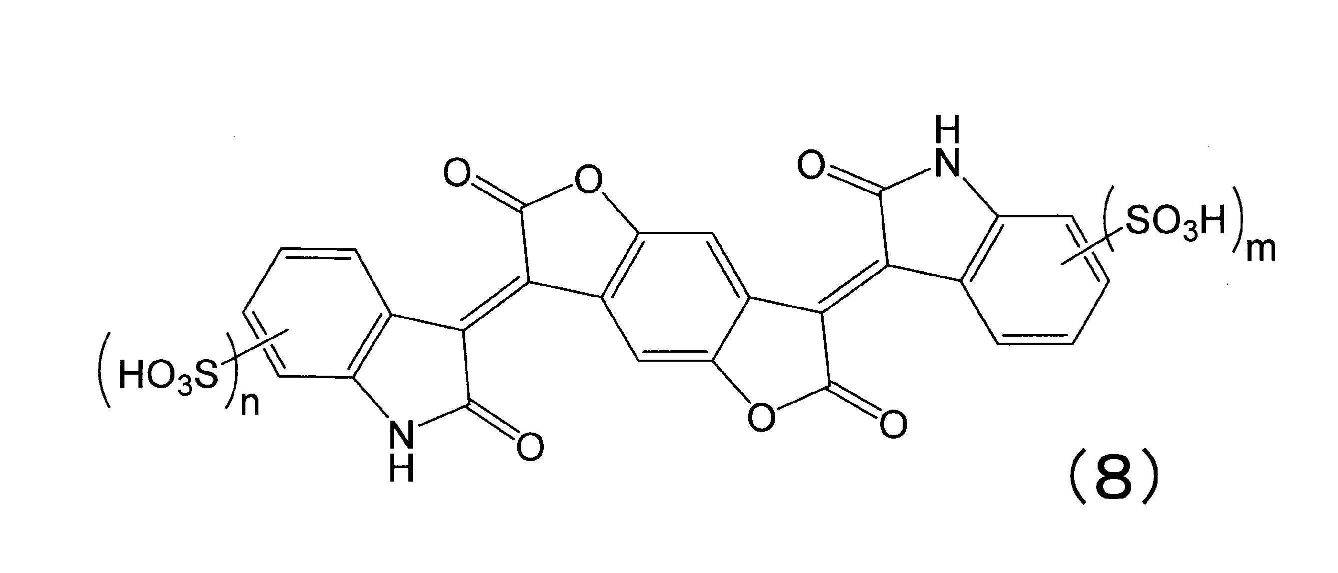
ただし、n+m≧1を満たす。
有機EL層をインクジェット法により形成する場合には、本発明に用いられる感光性樹脂組成物が、撥液材料を含有することが好ましい。フッ素系ポリマーやシラン化合物を有するフッ素含有化合物など公知のものを利用することができるが、少なくともアミド基またはウレタン基を有する撥液材料が好ましい。アミド基またはウレタン基を有することで、前述のするアルカリ可溶性樹脂(A)との相溶性が向上し、ハジキ等の欠点を低減させ、硬化膜の膜厚均一性を向上する効果があり、その結果として、表示装置の表示不良を低減する。
本発明の有機EL表示装置において、スペーサ4は、画素分割層上に設けられる。第一の目的として、スペーサを設けることで、有機EL層を形成する際の基板と蒸着マスクとの接触面積を小さくでき、それにより、工程中でのパーティクル発生を抑制することができる。この結果、パネルの歩留まり低下や、発光素子の劣化を抑制することができる。また第二の目的として、前述したように、後工程において第二電極上を覆う構造物を支え、表示装置の強度を確保するため、画素分割層上にスペーサを作製する必要がある。スペーサは、画素分割層と同様にパターニング加工が必須であり、除去部の残渣は、短絡や黒点などの欠陥に直結する場合がある。さらに、スペーサの縁の形状によっては第二電極の断線の原因となるため、なだらかな順テーパー形状であることなどの加工性も求められる。
本発明の有機EL表示装置において、有機EL層5の構成は特に限定されず、例えば、(1)正孔輸送層/発光層、(2)正孔輸送層/発光層/電子輸送層、(3)発光層/電子輸送層のいずれであってもよい。さらに、上記の構成を、電荷発生層を介して複数積層したタンデム型であってもよい。電荷発生層は、一般的に、電子引抜層、接続層、中間層、中間電極、中間導電層、中間絶縁層とも呼ばれ、公知の材料構成を用いることができる。タンデム型とすることで、発光輝度や発光寿命の向上が期待できるため好ましい。タンデム型の具体例は、例えば(4)正孔輸送層/発光層/電子輸送層/電荷発生層/正孔輸送層/発光層/電子輸送層、(5)正孔注入層/正孔輸送層/発光層/電子輸送層/電子注入層/電荷発生層/正孔注入層/正孔輸送層/発光層/電子輸送層/電子注入層、(6)正孔輸送層/発光層/電子輸送層/電荷発生層/正孔輸送層/発光層/電子輸送層/電荷発生層/正孔輸送層/発光層/電子輸送層、といった、陽極と陰極の間に電荷発生層を含む積層構成が挙げられる。
正孔輸送層は、例えば、正孔輸送材料の一種または二種以上を積層または混合する方法や、正孔輸送材料と高分子結着剤の混合物を用いる方法により形成される。また、正孔輸送材料に塩化鉄(III)のような無機塩を添加して正孔輸送層を形成してもよい。正孔輸送材料は、発光素子の作製に必要な薄膜を形成し、陽極となる電極から正孔が注入できて、さらに正孔を輸送できる化合物であれば特に限定されない。正孔輸送層は、単層であっても複数の層が積層されて構成されていてもよい。
発光層では、注入された電子と正孔とが再結合し発光する。この発光層を構成する材料を選ぶことにより、様々な多色発光が可能であることが有機EL表示装置の大きな特徴である。
電子輸送層は、陰極から注入された電子を発光層まで輸送する層である。低駆動電圧を達成するためにも、本発明の有機EL層が、電子輸送層を含むことが好ましい。電子輸送層には、電子注入効率が高く、注入された電子を効率良く輸送することが望まれる。そのため、電子輸送層は、電子親和力および電子移動度が大きく、安定性に優れ、トラップとなる不純物が製造時および使用時に発生しにくい物質であることが好ましい。特に、膜厚が大きい場合には、低分子量の化合物は結晶化するなどして膜質が劣化しやすいため、分子量400以上の化合物が好ましい。なお、正孔と電子の輸送バランスを考えた場合に、再結合しなかった正孔が陽極から陰極側へ流れることを効率よく阻止できる役割を電子輸送層が有することも好ましく、本発明における電子輸送層には、正孔の移動を効率よく阻止できる正孔阻止層も同義のものとして含まれる。電子輸送層は、単層であっても複数の層が積層されて構成されていてもよい。
電荷発生層は、一般に二重層からなり、具体的には、n型電荷発生層およびp型電荷発生層からなるpn接合型電荷発生層を用いることができる。上記pn接合型電荷発生層は、有機EL層中で電圧が印加されることにより、電荷を発生、または電荷を正孔および電子に分離し、これらの正孔および電子を正孔輸送層および電子輸送層を経由して発光層に注入する。具体的には、有機EL層に含まれる複数の発光層に対して、中間の電荷発生層として機能する。n型電荷発生層は陽極側に存在する発光層に電子を供給し、p型電荷発生層は陰極側に存在する発光層に正孔を供給する。そのため、複数の発光層を含む有機EL層における発光輝度と発光効率をより向上させ、駆動電圧を下げることができ、有機EL層の発光寿命もより向上させることができる。このようなことから、本発明において有機EL層が、電荷発生層を含むことが好ましい。さらに、後述するように、本発明において電荷発生層が、ドナー性ドーパント材料を含むことが好ましく、ドナー性ドーパント材料が、アルカリ金属、アルカリ土類金属、希土類金属、該金属類の無機塩、該金属類と有機物との錯体からなる群より選択される1種以上のものを含有することが好ましい。
本発明において、電子輸送層および/または電荷発生層は、下記一般式(1)で表されるフェナントロリン骨格を有する化合物を含むことが好ましい。


本発明において第二電極6は、ボトムエミッション型の場合には光反射性の電極、トップエミッション型の場合には光透過性の電極である必要がある。
本発明においては、上述のとおり、基材1に含まれるものとして配線やTFT7などの駆動回路が設けられる場合がある。
特にアクティブ駆動型のように、例えば図2に示されるように基材1の内部に配線やTFT7が設けられる場合、平坦化層8を用いることが好ましい。平坦化層8を設けることにより、配線やTFT7の凹凸を覆い、平坦化することができる。この場合、平坦化層上に第一電極2が設けられるため、第一電極2と配線やTFT7とは、平坦化層8に形成されたコンタクトホールを介して接続することが好ましい。平坦化層8としては、公知の有機物または無機物のどちらにも限定されないが、加工性の面から感光性樹脂組成物の硬化膜を含むことが好ましい。平坦化層8は、大判基板に薄い膜を均一に形成することができるスピンコート法、スリットコート法、ディップコート法、スプレーコート法、印刷法などのウェットコーティング法で塗布することができる。
第二電極を形成後、例えば図5に示されるように封止層9により封止をおこなうことが好ましい。有機ELの発光素子が酸素や水分に弱いとされるためであり、信頼性の高い表示装置を得るためにはできるだけ酸素と水分の少ない雰囲気下で封止をおこなうことが好ましい。封止層9に使用する部材についても、ガスバリア性の高いものを選定することが好ましく、基材1同様にガラス、樹脂フィルム、ガスバリア膜などから適宜選択する。例えば、ガスバリア膜の一例として、SiO2(酸化シリコン)、SiN(窒化シリコン)、SiON(酸窒化シリコン)などの材料が挙げられる。また、SiO2(酸化シリコン)、SiN(窒化シリコン)、SiON(酸窒化シリコン)などの材料を用い形成された層の上に、アクリル樹脂、シリコーン樹脂などの樹脂材料からなる封止層9を設けてもよい。トップエミッション型である表示装置の場合においては、光透過性の材料で形成されることが好ましい。
本発明の有機EL表示装置は、例えば図5に示されるようにさらに偏光層10を有することが好ましい。具体的には直線偏光層とλ/4位相差層とが積層され、表示装置に外部から入射した光の反射を抑制する。直線偏光層としては、特に限定されないが、例えば、ポリビニルアルコール系フィルムをヨウ素で染色し一軸延伸して得られるフィルムが多く用いられている。λ/4位相差層を構成する材料としても、特に限定されないが、耐熱性を有するポリイミド系樹脂などが好ましい。
本発明の有機EL表示装置は、例えば図5に示されるようにさらに紫外線吸収層11を有することが好ましい。紫外線吸収層11を有することにより、紫外線による基板や有機EL層5の劣化を抑制し、表示装置の信頼性を向上させることができる。紫外線吸収層11としては、波長320nm以下の光を吸収する層が好ましく、波長360nm以下の光を吸収する層がより好ましく、波長420nm以下の光を吸収する層がさらに好ましい。ただし、波長420nm以上の光は表示に用いる青色の発光波長と重複するため、紫外線吸収層11は、波長420nm以上の領域において高い透過率を有することが好ましい。このことは、本発明の有機EL表示装置が屋外で使用される場合において特に有効である。
本発明の有機EL表示装置の製造方法は、基材1上に第一電極2、画素分割層3、スペーサ4を有する基板、さらに、有機EL層5および第二電極6を有する有機EL表示装置の製造方法であって、画素分割層3とスペーサ4を一括加工する工程を有し、一括加工のためのフォトマスクが、透光部、遮光部および半透光部を有するハーフトーンフォトマスクである。
各実施例および比較例における画素分割層とスペーサの膜厚は、パターン付き基板(100mm×100mm)の画素分割層とスペーサの段差より、表面粗さ測定機(サーフコム1400D、(株)東京精密製)を使用して測定した。テーパーの様子は、パターン付き基板を切断した断面を、走査型電子顕微鏡(SEM、S-3000N、日立ハイテクノロジーズ社製)で観察した。
各実施例および比較例における画素分割層とスペーサの表面粗さは、パターン付き基板(100mm×100mm)の画素分離層とスペーサ上を、原子間力顕微鏡(AFM、Dimension Icon、ブルカー社製)で観察した結果のうち、算術平均粗さ(Ra)を採用した。観察条件としては、RTESP-300プローブ、タッピングモード、スキャンサイズ5μm□、スキャンレート0.1Hz、サンプルライン数1024本とした。
各実施例および比較例における画素分割層に含まれるシリカ粒子は、透過型電子顕微鏡-エネルギー分散型X線分光法(TEM-EDX)により倍率50000倍の条件で観測した撮像を、画像解析式粒度分布測定機(Mac-View、MOUNTECH社製)を用いて、測定した。すなわち、パターン付き基板(100mm×100mm)の画素分割層の断面においてTEMの撮像上のシリカ粒子を無作為に30個選び(試験n数30)、それぞれについてTEMの撮像上の長径、短径およびアスペクト比を測定し、長径(nm)が5~30nmであり、かつアスペクト比が1.0~1.5の範囲にあるシリカ粒子を(a)成分と定義した。なお、1個のシリカ粒子についてTEMの撮像上の短径と長径が等しい場合、すなわち真円であった場合は、その直径を長径とみなした。(a)成分に該当するシリカ粒子の特徴を示す代表値としては、一次粒子径の平均値、すなわち、長径の平均値を算出し、小数点第一位を四捨五入した値、および、アスペクト比の平均値、すなわち、(a)成分に該当する個々のシリカ粒子のアスペクト比の平均値を算出し、小数点第二位を四捨五入した値を用いた。
各実施例および比較例における基板の拡散反射光測定は、パターン付き基板(100mm×100mm)の、画素分離層とスペーサが形成された面を、分光測色計(CM-2600d、コニカミノルタジャパン社製)で測定し、正反射光除去であるSCEモードにおける波長550nmの拡散反射率を採用した。拡散反射率が高いほど正反射光を抑制できているとして、特性良好と判定した。
各実施例および比較例における有機EL表示装置の密着性試験は、図7に示すように、発光素子が形成された基板(100mm×100mm)の、発光素子が形成された面と反対面の中央部に直径5mmの金属円柱を固定し、この円柱に沿って、円柱の抱き角0°(基板が平面の状態)から、円柱への抱き角が180°(円柱で折り返した状態)となる範囲で、繰り返し折り曲げ動作を行った後、折り曲げ部を光学顕微鏡で観察した。剥離発生が、折り曲げ動作1~100回であったものは密着性が低く特性(C)、101~1000回であったものを特性(B)、1001回以上であったものは密着性が高く特性(A)と判定した。なお、試験は10回行い(試験n数10)、剥離発生までの回数が最も小さい結果を採用した。
各実施例および比較例における有機EL表示装置の耐候信頼性試験は、後述する各実施例および比較例で作製した有機EL表示装置の、室温23℃湿度45%で24時間放置後の様子を確認した。試験には表示装置を10個投入し(試験n数10)、第二電極に腐食が観察されなかった場合は、耐候信頼性良好として(A)、一つでも腐食が観察された場合は、第二電極にピンホール有りとして(B)の判定とした。
各実施例および比較例における有機EL表示装置の電気信頼性試験は、後述する各実施例および比較例で作製した有機EL表示装置において、隣接する2本のストライプ状第一電極間に電圧5Vを印加した際の電流値を測定した。測定には、ソースメータ(2400、ケースレーインスツルメンツ(株)製)を使用し、電流値が小さいほど漏れ電流が少なく特性良好と判定した。なお、試験は20か所で行い(試験n数20)、測定結果の大小5つずつを除いた10回分の平均値を採用した。
各実施例および比較例における有機EL表示装置の発光特性試験は、後述する各実施例および比較例で作製した有機EL表示装置において、交差する第一電極と第二電極を1対選択した1つの発光素子に、10mA/cm2の電流を流した際の電圧と輝度を測定した。電圧の測定にはソースメータ(2400、ケースレーインスツルメンツ(株)製)を使用し、輝度の測定には分光放射輝度計(CS-1000、コニカミノルタ社製)を使用した。
各実施例および比較例における第一電極とハーフトーンフォトマスクの設計を、図6に示す。図6aのように、第一電極2は、基材1(100mm×100mm)の中央部に、線幅60μm、100μmピッチ、長さ10mm、100本をストライプ状に作製した。すなわち基材1の露出部分は40μm幅となる。これに対して、ポジ型用ハーフトーンフォトマスクbは、遮光部14がスペーサ、半透光部13が画素分割層となるように、100μmピッチで各線幅を調整した。ネガ型用ハーフトーンフォトマスクcは透光部12がスペーサ、半透光部13が画素分割層となるように、各線幅IとIIを調整した。いずれの場合も、画素分割層とスペーサが第一電極の空隙に配置されるよう図6のように位置合わせをおこなった。完成した基板においては、線幅Iが画素分割層と有機EL層の接する界面、線幅IIがスペーサと有機EL層の接する界面に相当する。
各実施例および比較例で用いた感光性樹脂組成物R-1~R-15は、次のようにして調製した。なお、用いた化合物のうち略語を使用しているものについて、名称を以下に示す。
BAHF:2,2-ビス(3-アミノ-4-ヒドロキシフェニル)ヘキサフルオロプロパン
BFE:1,2-ビス(4-ホルミルフェニル)エタン
BIP-PHBZ:4,4’,4”-メチリデントリスフェノール(旭有機材(株)製)
BYK-333:シリコーン系界面活性剤“BYK”(登録商標)333(ビックケミー社製)
DAE:ジアミノジフェニルエーテル
DFA:N,N-ジメチルホルムアミドジメチルアセタール
DMAA:N,N-ジメチルアクリルアミド
DPCA-60:カプロラクトン6モル変性ジペンタエリスリトールヘキサアクリレート(ペンチレンオキシ鎖を6個有する6官能アクリレート、日本化薬(株)製)
EL:乳酸エチル
FAMAC-6:2-(パーフルオロヘキシル)エチルメタクリレート
GBL:γ-ブチロラクトン
GMA:グリシジルメタクリレート
HA:ヒドロキシ基含有ジアミン化合物
HMOM-TPHAP:フェノール性水酸基を有し、かつフェノール性水酸基の両オルト位に分子量40以上の置換基を有する、下記化学式に示す化合物(本州化学工業(株)製)
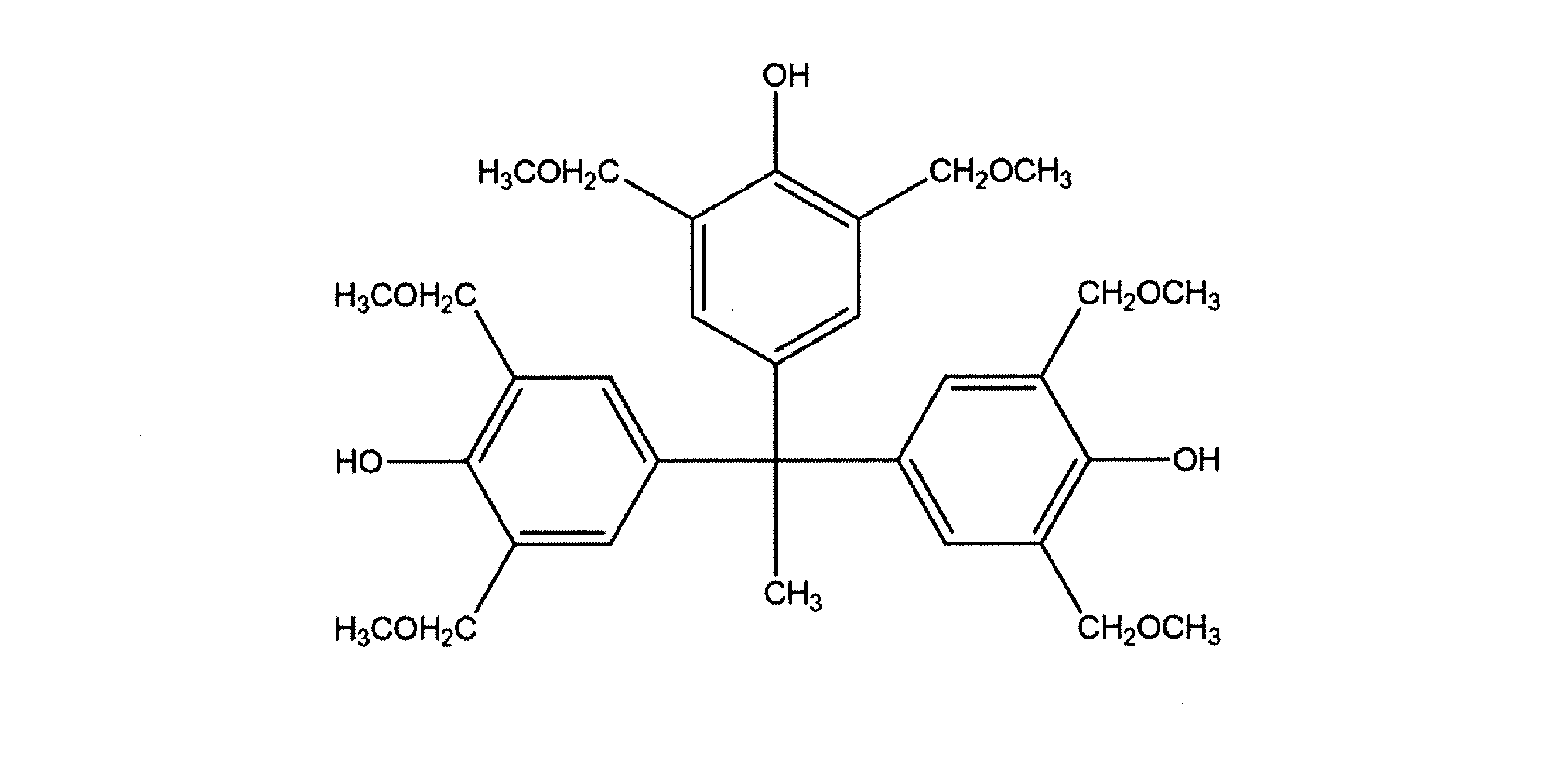
MAP:3-アミノフェノール;メタアミノフェノール
MBA:3-メトキシ-n-ブチルアセテート
MEK-ST-40:シリカ粒子分散液(日産化学工業(株)製)。溶剤種はメチルエチルケトンである
MEK-ST-L:シリカ粒子分散液(日産化学工業(株)製)。溶剤種はメチルエチルケトンである
MeTMS:メチルトリメトキシシラン
NA:5-ノルボルネン-2,3-ジカルボン酸無水物;ナジック酸無水物
TMOS:テトラメトキシシラン
NCI-831:”アデカアークルズ”(登録商標)NCI-831((株)ADEKA製)
NMP:N-メチル-2-ピロリドン
ODPA:ビス(3,4-ジカルボキシフェニル)エーテル二無水物;オキシジフタル酸二無水物
OSCAL-1421:シリカ粒子分散液(日揮触媒化成工業(株)製)。溶剤種はイソプロピルアルコールである
PGME:プロピレングリコールモノメチルエーテル
PGMEA:プロピレングリコールモノメチルエーテルアセテート
PhTMS:フェニルトリメトキシシラン
S0100CF:Irgaphor Black(登録商標)S0100CF
SiDA:1,3-ビス(3-アミノプロピル)テトラメチルジシロキサン
S-20000:“SOLSPERSE”(登録商標) 20000(ポリエーテル系分散剤、Lubrizol製)
TMSSucA:3-トリメトキシシリルプロピルコハク酸無水物
TrisP-PA:1,1-ビス(4-ヒドロキシフェニル)-1-[4-[1-(4-ヒドロキシフェニル)-1-メチルエチル]フェニル]エタン(本州化学工業(株)製)
WR-301:“ADEKA ARKLS”(登録商標)WR-301((株)ADEKA製)
カレンズMOI-BM:メタクリル酸2-(0-[1’-メチルプロピリデンアミノ]カルボキシアミノ)エチル
ビスフェノールAF:2,2-ビス(4-ヒドロキシフェニル)ヘキサフルオロプロパン(セントラル硝子(株)製)
6FDA:2,2-(3,4-ジカルボキシフェニル)ヘキサフルオロプロパン二無水物;4,4’-ヘキサフルオロプロパン-2,2-ジイル-ビス(1,2-フタル酸無水物)
顔料分散剤1:特開2020/70352号の合成例2で開示された顔料分散剤1(固形分100重量%)。直鎖状ポリアルキレンアミン構造とポリエーテル系高分子鎖とを有するポリマー型分散剤。
乾燥窒素気流下、三口フラスコに、BAHFを31.13g(0.085mol;全アミンおよびその誘導体に由来する構造単位に対して77.3mol%)、SiDAを1.24g(0.0050mol;全アミンおよびその誘導体に由来する構造単位に対して4.5mol%)、末端封止剤として、MAPを2.18g(0.020mol;全アミンおよびその誘導体に由来する構造単位に対して18.2mol%)、NMPを150.00g秤量して溶解させた。ここに、NMP50.00gにODPAを31.02g(0.10mol;全カルボン酸およびその誘導体に由来する構造単位に対して100mol%)溶かした溶液を添加し、20℃で1時間攪拌し、次いで50℃で4時間攪拌した。その後、キシレン15gを添加し、水をキシレンとともに共沸しながら、150℃で5時間攪拌した。反応終了後、反応溶液を水3Lに投入し、析出した固体沈殿を濾過して得た。得られた固体を水で3回洗浄した後、80℃の真空乾燥機で24時間乾燥し、ポリイミド樹脂(PI-1)を得た。得られたポリイミド樹脂(PI-1)の重量平均分子量(Mw)は27,000、酸当量は350であった。
三口フラスコに、BAHFを18.31g(0.05mol)、プロピレンオキシドを17.42g(0.3mol)、アセトンを100mL秤量して溶解させた。ここに、アセトン10mLに塩化3-ニトロベンゾイルを20.41g(0.11mol)溶かした溶液を滴下した。滴下終了後、-15℃で4時間反応させ、その後室温に戻した。析出した白色固体を濾取し、50℃で真空乾燥させた。得られた固体30gを、300mLのステンレスオートクレーブに入れ、2-メトキシエタノール250mLに分散させ、5%パ
ラジウム-炭素を2g加えた。ここに水素を風船で導入して、室温で2時間反応させた。2時間後、風船がこれ以上しぼまないことを確認した。反応終了後、濾過して触媒であるパラジウム化合物を除去し、減圧留去させて濃縮し、下記構造のヒドロキシ基含有ジアミン化合物(HA)を得た。

乾燥窒素気流下、三口フラスコに、6FDAを44.42g(0.10mol;全カルボン酸およびその誘導体に由来する構造単位に対して100mol%)、NMPを150g秤量して溶解させた。ここに、NMP50gにBAHFを14.65g(0.040mol;全アミンおよびその誘導体に由来する構造単位に対して32.0mol%)、HAを18.14g(0.030mol;全アミンおよびその誘導体に由来する構造単位に対して24.0mol%)、SiDAを1.24g(0.0050mol;全アミンおよびその誘導体に由来する構造単位に対して4.0mol%)溶かした溶液を添加し、20℃で1時間攪拌し、次いで50℃で2時間攪拌した。次に、末端封止剤として、NMP15gにMAPを5.46g(0.050mol;全アミンおよびその誘導体に由来する構造単位に対して40.0mol%)溶かした溶液を添加し、50℃で2時間攪拌した。その後、NMP15gにDFAを23.83g(0.20mol)溶かした溶液を投入した。投入終了後、50℃で3時間攪拌した。反応終了後、反応溶液を室温に冷却した後、反応溶液を水3Lに投入し、析出した固体沈殿を濾過して得た。得られた固体を水で3回洗浄した後、80℃の真空乾燥機で24時間乾燥し、ポリイミド前駆体樹脂(PIP-1)を得た。得られたポリイミド前駆体樹脂(PIP-1)の重量平均分子量(Mw)は20,000、酸当量は450であった。
乾燥窒素気流下、合成例2で得られたHAを21.2g(0.035mol)、DAEを7.0g(0.035mol)、SiDAを1.2g(0.005mol)をNMP400gに溶解した。ここに、ODPA31.0g(0.10mol)をNMP50gとともに加えて、40℃で1時間撹拌した。その後、MAP5.5g(0.050mol)を加えて40℃で1時間撹拌した。さらに、NMP10gにDFAを8.3g(0.07mol)を溶かした溶液を投入した。投入終了後、40℃で3時間攪拌した。撹拌終了後、溶液を室温まで冷却した後、溶液を水3Lに投入して白色沈殿を得た。この沈殿を濾過で集めて、水で3回洗浄した後、50℃の真空乾燥機で72時間乾燥し、酸当量275g/molのポリイミド前駆体樹脂からなるアルカリ可溶性樹脂(PIP-2)を得た。
合成例4と同様の方法で投入するDFAの量を13.1g(0.11mol)とすることで酸当量329g/molのポリイミド前駆体樹脂からなるアルカリ可溶性樹脂(PIP-3)を得た。
合成例4と同様の方法で投入するDFAの量を16.7g(0.14mol)とすることで酸当量366g/molのポリイミド前駆体樹脂からなるアルカリ可溶性樹脂(PIP-4)を得た。
トルエンを満たしたディーンスターク水分離器および冷却管を付けた500mL丸底フラスコに、BAHFを34.79g(0.095mol;全アミンおよびその誘導体に由来する構造単位に対して95.0mol%)、SiDAを1.24g(0.0050mol;全アミンおよびその誘導体に由来する構造単位に対して5.0mol%)、NMPを75.00g秤量して、溶解させた。ここに、NMP25.00gに、BFEを19.06g(0.080mol;全カルボン酸およびその誘導体に由来する構造単位に対し66.7mol%)、末端封止剤として、NAを6.57g(0.040mol;全カルボン酸およびその誘導体に由来する構造単位に対し33.3mol%)溶かした溶液を添加し、20℃で1時間攪拌し、次いで50℃で1時間攪拌した。その後、窒素雰囲気下、200℃以上で10時間加熱攪拌し、脱水反応を行った。反応終了後、反応溶液を水3Lに投入し、析出した固体沈殿を濾過して得た。得られた固体を水で3回洗浄した後、80℃の真空乾燥機で24時間乾燥し、ポリベンゾオキサゾール樹脂(PBO-1)を得た。得られたポリベンゾオキサゾール樹脂(PBO-1)の重量平均分子量(Mw)は25,000、酸当量は330であった。
トルエンを満たしたディーンスターク水分離器および冷却管を付けた500mL丸底フラスコに、BAHFを34.79g(0.095mol;全アミンおよびその誘導体に由来する構造単位に対して95.0mol%)、SiDAを1.24g(0.0050mol;全アミンおよびその誘導体に由来する構造単位に対して5.0mol%)、NMPを70.00g秤量して、溶解させた。ここに、NMP20.00gに、BFEを19.06g(0.080mol;全カルボン酸およびその誘導体に由来する構造単位に対し66.7mol%)溶かした溶液を添加し、20℃で1時間攪拌し、次いで50℃で2時間攪拌した。
三口フラスコに、MeTMSを23.84g(35mol%)、PhTMSを49.57g(50mol%)、TMOSを3.81g(5mol%)、PGMEAを76.36g仕込んだ。フラスコ内に空気を0.05L/分で流し、混合溶液を攪拌しながらオイルバスで40℃に加熱した。混合溶液をさらに攪拌しながら、水28.38gにリン酸0.271gを溶かしたリン酸水溶液を10分かけて滴下した。滴下終了後、40℃で30分間攪拌して、シラン化合物を加水分解させた。加水分解終了後、PGMEA8.48gにTMSSucA13.12g(10mol%)を溶かした溶液を添加した。その後、バス温を70℃にして1時間攪拌した後、続いてバス温を115℃まで昇温した。昇温開始後、約1時間後に溶液の内温が100℃に到達し、そこから2時間加熱攪拌した(内温は100~110℃)。2時間加熱攪拌して得られた樹脂溶液を氷浴にて冷却した後、陰イオン交換樹脂および陽イオン交換樹脂を、それぞれ樹脂溶液に対して2重量%加えて12時間攪拌した。攪拌後、陰イオン交換樹脂および陽イオン交換樹脂を濾過して除去し、ポリシロキサン樹脂溶液(PS-1)を得た。得られたポリシロキサン樹脂の重量平均分子量(Mw)は4,200であり、カルボン酸当量(酸当量)は700g/molであった。
乾燥窒素気流下、TrisP-PA(商品名、本州化学工業(株)製)21.22g(0.05モル)と5-ナフトキノンジアジドスルホニル酸クロリド36.27g(0.135モル)を1,4-ジオキサン450gに溶解させ、室温にした。ここに、1,4-ジオキサン50gと混合したトリエチルアミン15.18gを、系内が35℃以上にならないように滴下した。滴下後30℃で2時間撹拌した。トリエチルアミン塩を濾過し、ろ液を水に投入した。その後、析出した沈殿を濾過で集めた。この沈殿を真空乾燥機で乾燥させ、下記構造の感光剤(キノンジアジド化合物b-1)を得た。

セパラブルフラスコに塩基性染料としてC.I.ベーシックブルー7 9.25g(0.018モル)、純水200gを投入し、60℃にて30分攪拌した。酸性染料としてC.I.アシッドレッド52 11.50g(0.019.8モル)を純水120gに溶解させた水溶液を投入後、60℃にて60分攪拌した。その後、加熱を停止し室温まで攪拌冷却した。室温まで冷却後、反応液を濾過し、紫色の固体を得た。この固体を減圧下60℃で8時間乾燥させ、造塩化合物d-1を得た。
d-1と同様の手法で、塩基性染料としてC.I.ベーシックブルー7の代わりにC.I.ベーシックブルー26を用いて、造塩化合物d-2を得た。
溶剤成分である742.39gのPGMEA中に、塩基性基を有する顔料分散剤である15.00gのS-20000を添加した後に、4-メチルベンゼンスルホン酸を1.00重量%含有するPGMEA溶液を2.70g添加した。次いで、大気圧下/液温25℃で1時間撹拌後、さらに6時間静置させることにより、S-20000が有する塩基性基と、4-メチルベンゼンスルホン酸が有するスルホ基とを、予め塩形成させた。さらに、149.91gのアルカリ可溶性樹脂溶液(上記PIP-1を、固形分30重量%となるようにPGMEAを用いて溶解して得られた樹脂溶液(固形分30.0重量%))を加え、30分間撹拌した後に、90.00gの下記の構造で表されるベンゾジフラノン系黒色顔料を混合して20分間撹拌し、予備分散液を得た。分散用メディアとして、0.4mmφのジルコニアビーズ(“トレセラム”(登録商標)、東レ(株)製)が75体積%充填されたビーズミルに予備分散液を送液して分散処理を1回行い、次いで、循環式で湿式メディア分散処理を行った。30分間を経過して以降、分散処理時間が10分間経過するごとに分散機の吐出口からガラス瓶容器の中へ適量抜き出してサンプリングした顔料分散液を、レーザー回折・散乱法粒度分布測定装置(UPA150、Microtrac社製)にセットして平均分散粒子径を測定した。サンプリングしてから30分間経過した時点での平均分散粒子径が、メジアン径D50(累積50%体積平均径)として150±10nmであり、かつメジアン径D90(累積90%体積平均径)として300±30nmの範囲内となった顔料分散液を、「顔料分散液1」とした。

「顔料分散液1」と同様の手順で、PIP-1の溶解をPGMEAに替えてMBAを用いて、「顔料分散液2」を調製した。
熱プラズマ法により製造した窒化ジルコニウム粒子(ZrN、日清エンジニアリング(株)製)200g、ポリイミド前駆体樹脂(PIP-1)50g、およびγ-ブチロラクトン(GBL)1000gをタンクに仕込み、ホモミキサーで20分撹拌し、予備分散液を得た。0.05mmφジルコニアビーズを75体積%充填した遠心分離セパレーターを具備した分散機(ウルトラアペックスミル、(株)広島メタル&マシナリー製)に、得られた予備分散液を供給し、回転速度10m/sで3時間分散を行い、固形分濃度20重量%、着色材/樹脂(重量比)=80/20の顔料分散液3を得た。組成を表1に示す。

顔料分散液3と同様の方法で、投入するアルカリ可溶性樹脂をPIP-2とすることで顔料分散液4を得た。
顔料分散液3と同様の方法で、投入するアルカリ可溶性樹脂をPIP-3とすることで顔料分散液5を得た。
顔料分散液3と同様の方法で、投入するアルカリ可溶性樹脂をPIP-4とすることで顔料分散液6を得た。
溶剤である770.00gのPGMEAに、30.00gの顔料分散剤1を添加し、5分間攪拌した後に、100.00gのZCR-1569Hを添加して30分間撹拌した。さらに、(b)成分として、100.00gのS0100CFを添加した後、30分間撹拌して予備攪拌液を得た。0.4mmφの複合酸化物からなる粉砕メディア(酸化ジルコニウム:酸化ハフニウム:酸化イットリウム:酸化アルミニウム=重量比93.3:1.5:4.9:0.3、東レ(株)製)が充填率75体積%でベッセル内に充填された縦型ビーズミルに予備攪拌液を送液し、循環方式で第一の湿式メディア分散処理を周速8m/sで3時間行った。さらに、0.05mmφの複合酸化物からなる粉砕メディア(酸化ジルコニウム:酸化ハフニウム:酸化イットリウム:酸化アルミニウム=重量比93.3:1.5:4.9:0.3、東レ(株)製)が充填率75体積%でベッセル内に充填された縦型ビーズミルに送液し、循環方式で第二の湿式メディア分散処理を周速9m/sで6時間行った後、口径0.8μmのフィルタで濾過を行い、固形分20.00重量%の顔料分散液1を調製した。各原料の配合重量を表2に示す。

黄色灯下、1:1の重量比率であるγ-ブチロラクトン(GBL)および乳酸エチル(EL)の(C)溶剤に、(A)アルカリ可溶性樹脂として合成例1で得たポリイミド前駆体樹脂PI-1、(B)感光剤として合成例10で得た化合物b-1、(D)着色材料のうち、酸性染料と塩基性染料からなる造塩化合物として化合物d-1、非イオン性染料d-3としてC.I.ソルベントブルー45、下記構造で表される熱発色性化合物f-1(BIP-PHBZ)、その他添加剤として熱架橋剤g-1(HMOM-TPHAP)、フェノール性水酸基を有する化合物h-1(ビスフェノールAF)、密着改良剤i-1(KBM-403)を、表3に示す量を添加し、攪拌して溶解させ、ポジ型感光性樹脂組成物R-1を調製した。


R-1の調製と同様に、R-2~6を表3に記載の組成にて調製した。
黄色灯下、感光剤である、0.20gのNCI-831を、13.01gのPGMEAに添加して3分間攪拌して溶解させた。これに、4.28gのアルカリ可溶性ポリイミド樹脂溶液A(PI-1を、固形分30重量%となるようにPGMEAを用いて溶解して得られた樹脂溶液)と、1.02gのアルカリ可溶性カルド樹脂溶液A(アミン価0(mgKOH/g)であり、樹脂酸価90(mgKOH/g)であり、固形分44.2重量%であり、アルカリ可溶性基としてカルボキシル基を有するアルカリ可溶性カルド樹脂のPGMEA溶液である、“ADEKA ARKLS”(登録商標)WR-301((株)ADEKA製))を添加し、2つ以上のラジカル重合性基を有する化合物である、0.99gのDPCA-60を添加して攪拌して調合液を得た。この調合液と、ガラス瓶容器の上澄み液からサンプリングした10.50gの顔料分散液1とを混合して30分間撹拌し、ネガ型感光性樹脂組成物R-7を得た。原料の配合量を表4に示す。

アルカリ可溶性ポリイミド樹脂溶液Aに替えてアルカリ可溶性ポリイミド樹脂溶液B(PI-1を、固形分30重量%となるようにMBAを用いて溶解して得られた樹脂溶液)を用いて、さらに顔料分散液1に替えて顔料分散液2を用いて、R-7と同様の手順で、ネガ型感光性樹脂組成物R-8を調製した。原料の配合量を表4に示す。
撹拌装置、還流冷却管、滴下ロート、温度計および窒素ガス吹き込み口を備えた1000mLの反応容器に、シクロヘキサノンを100重量部加えて、窒素ガス雰囲気下で110℃に昇温した。シクロヘキサノンの温度を110℃に維持し、表5に示すモノマー混合溶液を滴下ロートにより2時間で等速滴下して、各モノマー溶液を調製した。滴下終了後、モノマー溶液を、115℃まで昇温させ、2時間反応させて撥液材料(e-1)および(e-2)を得た。

乾燥窒素気流下、m-クレゾール108.0g(1.00モル)、37重量%ホルムアルデヒド水溶液75.5g(ホルムアルデヒド0.93モル)、シュウ酸二水和物0.63g(0.005モル)、メチルイソブチルケトン264gを仕込んだ後、油浴中に浸し、反応液を還流させながら、4時間重縮合反応を行った。その後、油浴の温度を3時間かけて昇温し、その後に、フラスコ内の圧力を4.0kPa~6.7kPaまで減圧し、揮発分を除去し、溶解している樹脂を室温まで冷却して、ノボラック型フェノール樹脂(j-1)を得た。GPCから重量平均分子量は3,500であった。
黄色灯下、表6に示す配合比で各成分を混合し、室温にて十分攪拌を行い溶解させた。その後、得られた溶液を孔径1μmのフィルターで濾過し、ポジ型感光性樹脂組成物R-9、R-10を得た。

93.8gの顔料分散液3に、アルカリ可溶性樹脂(PIP-1)を50.5g、光酸発生剤としてキノンジアジド化合物(b-1)を17.0g、フェノール化合物(h-1、ビスフェノールAF)を13.6g、シリコーン系界面活性剤(BYK-333)を0.2g、GBLを105.0g、PGMEを720.0g添加して、全固形分濃度10重量%、顔料/樹脂(重量比)=15/85のポジ型感光性樹脂組成物R-11を得た。組成を表7に示す。

R-11と同様の方法で、投入する顔料分散液として顔料分散液3を顔料分散液4に、アルカリ可溶性樹脂としてPIP-1をPIP-2に替えて、ポジ型感光性樹脂組成物R-12を得た。組成を表7に示す。
R-11と同様の方法で、投入する顔料分散液として顔料分散液3を顔料分散液5に、アルカリ可溶性樹脂としてPIP-1をPIP-3に替えて、ポジ型感光性樹脂組成物R-13を得た。組成を表7に示す。
R-11と同様の方法で、投入する顔料分散液として顔料分散液3を顔料分散液6に、アルカリ可溶性樹脂としてPIP-1をPIP-4に替えて、ポジ型感光性樹脂組成物R-14を得た。組成を表7に示す。
黄色灯下、(A)アルカリ可溶性樹脂としてポリイミド前駆体樹脂(PIP-1)(10.0g)、(B)感光剤としてf-1(1.2g)を(C)有機溶剤であるPGME(32.0g)とGBL(8.0g)に加えた。その後、得られた溶液を0.45μmφのフィルターで濾過し、ポジ型感光性樹脂組成物R-15を得た。
黄色灯下、8.50gのMBAと、16.16gのPGMEAとの混合溶剤中に、光重合開始剤として、0.38gのOXE03を添加して10分間攪拌して溶解させた。そこに、シリカ粒子分散液である(a)成分として、1.88gのMEK-ST-40を添加し10分間攪拌して溶解させた。次いで、4.61gのZAH-106と、0.45gのTR4020Gと、0.38gのDPCA-60と、0.97gのGA-5060Pとを添加して30分間攪拌し、透明の調合液を得た。この調合液に16.69gの顔料分散液7を混合して30分間撹拌して、固形分15.00重量%であるネガ型感光性樹脂組成物R-16を調製した。各原料の配合重量を表8に示す。

R-16の調製と同様に、MEK-ST-40に替えて、OSCAL-1421を用いて、表8に示す配合量で、ネガ型感光性樹脂組成物R-17を調製した。各原料の配合重量を表8に示す。
R-16の調製と同様に、MEK-ST-40に替えて、MEK-ST-Lを用いて、表8に示す配合量で、ネガ型感光性樹脂組成物R-18を調製した。各原料の配合重量を表8に示す。
各実施例および比較例における画素分割層とスペーサの表面粗さ、基板の拡散反射光、有機EL表示装置の密着性、耐候信頼性、電気信頼性、発光特性は、次のように評価した。


第一の発光ユニットのうち、電子輸送層にLiQを使わず化合物(ET-1)のみとした以外は実施例1と同様に有機EL表示装置を作製し、有機EL表示装置の密着性、耐候信頼性、電気信頼性、発光特性を評価した。感光性樹脂組成物とフォトマスクの条件を表9、評価結果を表10に示す。
第一の発光ユニットのうち、電子輸送層にLiQを使わず化合物(ET-2)のみとした以外は実施例1と同様に有機EL表示装置を作製し、有機EL表示装置の密着性、耐候信頼性、電気信頼性、発光特性を評価した。感光性樹脂組成物とフォトマスクの条件を表9、評価結果を表10に示す。
第一の発光ユニットのうち、電子輸送層にLiQを使わず化合物(ET-3)のみとした以外は実施例1と同様に有機EL表示装置を作製し、有機EL表示装置の密着性、耐候信頼性、電気信頼性、発光特性を評価した。感光性樹脂組成物とフォトマスクの条件を表9、評価結果を表10に示す。
第一の発光ユニットのうち、電子輸送層にLiQを使わず化合物(ET-4)のみとした以外は実施例1と同様に有機EL表示装置を作製し、有機EL表示装置の密着性、耐候信頼性、電気信頼性、発光特性を評価した。感光性樹脂組成物とフォトマスクの条件を表9、評価結果を表10に示す。
実施例1と同様に、パターン付き基板を得た後、有機EL層として第一の発光ユニットを積層した。その後、第一の発光ユニット上に、n型電荷発生層として、化合物(ET-1)と、ドーパント材料である金属Liとを、蒸着速度比が化合物(ET-1):Li=99:1となるように10nm蒸着し、次に、p型電荷発生層として、化合物(HT-1)を10nm蒸着した。
n型電荷発生層のうち、化合物(ET-1)を化合物(ET-2)とした以外は実施例30と同様に有機EL表示装置を作製し、有機EL表示装置の密着性、耐候信頼性、電気信頼性、発光特性を評価した。感光性樹脂組成物とフォトマスクの条件を表9、評価結果を表10に示す。
n型電荷発生層のうち、化合物(ET-1)を化合物(ET-3)とした以外は実施例30と同様に有機EL表示装置を作製し、有機EL表示装置の密着性、耐候信頼性、電気信頼性、発光特性を評価した。感光性樹脂組成物とフォトマスクの条件を表9、評価結果を表10に示す。
n型電荷発生層のうち、化合物(ET-1)を化合物(ET-4)とした以外は実施例30と同様に有機EL表示装置を作製し、有機EL表示装置の密着性、耐候信頼性、電気信頼性、発光特性を評価した。感光性樹脂組成物とフォトマスクの条件を表9、評価結果を表10に示す。
2 第一電極
3 画素分割層
4 スペーサ
5 有機EL層
6 第二電極
7 TFT
8 平坦化層
9 封止層
10 偏光層
11 紫外線吸収層
12 透光部
13 半透光部
14 遮光部
15 円柱
16 Ra1の測定対象範囲
17 Ra2の測定対象範囲
18 有機EL表示装置
19 発光素子
Claims (18)
- 基材上に第一電極、画素分割層、スペーサを有する基板、さらに、有機EL層および第二電極を有する有機EL表示装置であって、該画素分割層の表面粗さ(Ra1)と該スペーサの表面粗さ(Ra2)における最大値をRamaxとしたときに、Ramaxが1.0nm以上50nm以下である、有機EL表示装置。
- 前記Ra1がRamaxとなる、請求項1に記載の有機EL表示装置。
- 前記基板と前記有機EL層が接する界面の面積のうち、前記画素分割層と前記有機EL層が接する界面の面積が、50%以上である、請求項2に記載の有機EL表示装置。
- 前記Ra2がRamaxとなる、請求項1に記載の有機EL表示装置。
- 前記基板と前記有機EL層が接する界面の面積のうち、前記スペーサと前記有機EL層が接する界面の面積が、50%以上である、請求項4に記載の有機EL表示装置
- 前記Ra1とRa2との差の絶対値が、1.0nm以上である、請求項1~5のいずれかに記載の有機EL表示装置。
- 前記画素分割層が、一次粒子径5~30nmのシリカ粒子を含む、請求項1~6のいずれかに記載の有機EL表示装置。
- 前記画素分割層が、アルカリ可溶性樹脂を含有する感光性樹脂組成物の硬化膜を含む、請求項1~7のいずれかに記載の有機EL表示装置。
- 前記アルカリ可溶性樹脂が、アクリル樹脂、フェノール樹脂、ポリシロキサン樹脂、カルド樹脂、ポリイミド樹脂、ポリイミド前駆体樹脂、ポリベンゾオキサゾール樹脂、およびポリベンゾオキサゾール前駆体樹脂からなる群より選択される1種以上のものを含有する、請求項8に記載の有機EL表示装置。
- 前記感光性樹脂組成物が着色材料を含む、請求項8または9に記載の有機EL表示装置。
- 前記感光性樹脂組成物が撥液材料を含む、請求項8~10のいずれかに記載の有機EL表示装置。
- 前記有機EL層が、電子輸送層および/または電荷発生層を含む、請求項1~11のいずれかに記載の有機EL表示装置。
- 前記電子輸送層および/または電荷発生層が、ドナー性ドーパントを含む、請求項12に記載の有機EL表示装置。
- 前記ドナー性ドーパントが、アルカリ金属、アルカリ土類金属、希土類金属、該金属類の無機塩、該金属類と有機物との錯体からなる群より選択される1種以上のものを含有する、請求項13に記載の有機EL表示装置。
- 前記電子輸送層および/または電荷発生層が、下記一般式(1)で表されるフェナントロリン骨格を有する化合物を含む、請求項12~14のいずれかに記載の有機EL表示装置。

- 前記電子輸送層および/または電荷発生層が、下記一般式(2)で表されるフェナントロリン骨格を有する化合物を含む、請求項12~14のいずれかに記載の有機EL表示装置。

- 基材上に第一電極、画素分割層、スペーサを有する基板、さらに、有機EL層および第二電極を有する有機EL表示装置の製造方法であって、画素分割層とスペーサを一括加工する工程を有し、一括加工のためのフォトマスクが、透光部、遮光部および半透光部を有するハーフトーンフォトマスクである、有機EL表示装置の製造方法。
- 前記半透光部の透過率が、前記透光部の透過率の15~50%である、請求項17に記載の有機EL表示装置の製造方法。
Priority Applications (3)
| Application Number | Priority Date | Filing Date | Title |
|---|---|---|---|
| CN202280021295.3A CN116982407A (zh) | 2021-03-26 | 2022-03-22 | 有机el显示装置及其制造方法 |
| KR1020237028291A KR20230162926A (ko) | 2021-03-26 | 2022-03-22 | 유기 el 표시 장치 및 그 제조 방법 |
| JP2022520873A JPWO2022202782A1 (ja) | 2021-03-26 | 2022-03-22 |
Applications Claiming Priority (2)
| Application Number | Priority Date | Filing Date | Title |
|---|---|---|---|
| JP2021-052862 | 2021-03-26 | ||
| JP2021052862 | 2021-03-26 |
Publications (1)
| Publication Number | Publication Date |
|---|---|
| WO2022202782A1 true WO2022202782A1 (ja) | 2022-09-29 |
Family
ID=83397481
Family Applications (1)
| Application Number | Title | Priority Date | Filing Date |
|---|---|---|---|
| PCT/JP2022/013062 WO2022202782A1 (ja) | 2021-03-26 | 2022-03-22 | 有機el表示装置およびその製造方法 |
Country Status (5)
| Country | Link |
|---|---|
| JP (1) | JPWO2022202782A1 (ja) |
| KR (1) | KR20230162926A (ja) |
| CN (1) | CN116982407A (ja) |
| TW (1) | TW202308457A (ja) |
| WO (1) | WO2022202782A1 (ja) |
Citations (10)
| Publication number | Priority date | Publication date | Assignee | Title |
|---|---|---|---|---|
| JP2001267080A (ja) * | 2000-01-14 | 2001-09-28 | Toray Ind Inc | 発光素子 |
| JP2008218421A (ja) * | 1996-09-12 | 2008-09-18 | Mitsubishi Chemicals Corp | 有機電界発光素子及びその製造方法 |
| WO2012086610A1 (ja) * | 2010-12-20 | 2012-06-28 | 旭硝子株式会社 | 感光性樹脂組成物、隔壁、カラーフィルタおよび有機el素子 |
| JP2013506984A (ja) * | 2009-09-30 | 2013-02-28 | オスラム オプト セミコンダクターズ ゲゼルシャフト ミット ベシュレンクテル ハフツング | 有機電子装置およびその製造方法 |
| KR20170112304A (ko) * | 2016-03-31 | 2017-10-12 | 엘지디스플레이 주식회사 | 유기발광 표시장치 및 이의 제조방법 |
| JP6319319B2 (ja) * | 2013-11-01 | 2018-05-09 | コニカミノルタ株式会社 | 有機エレクトロルミネッセンス素子、表示装置及び照明装置 |
| KR20190053606A (ko) * | 2017-11-10 | 2019-05-20 | 주식회사 진웅산업 | 페난트롤린 화합물 및 이를 포함하는 유기발광소자 |
| US20200091257A1 (en) * | 2018-09-14 | 2020-03-19 | Boe Technology Group Co., Ltd. | Oled display panel, display apparatus and method of manufacturing oled display panel |
| WO2020120791A1 (en) * | 2018-12-14 | 2020-06-18 | Novaled Gmbh | Organic light emitting device, a method for manufacturing the same and a composition for use therein |
| US20200235172A1 (en) * | 2019-01-21 | 2020-07-23 | Samsung Display Co., Ltd. | Organic light-emitting display device and method of manufacturing the same |
Family Cites Families (2)
| Publication number | Priority date | Publication date | Assignee | Title |
|---|---|---|---|---|
| JP3705283B2 (ja) | 2002-10-03 | 2005-10-12 | セイコーエプソン株式会社 | 表示パネル及びその表示パネルを備えた電子機器 |
| US11296156B2 (en) | 2018-11-28 | 2022-04-05 | Lg Display Co., Ltd. | Organic light emitting diode device |
-
2022
- 2022-03-22 JP JP2022520873A patent/JPWO2022202782A1/ja active Pending
- 2022-03-22 CN CN202280021295.3A patent/CN116982407A/zh active Pending
- 2022-03-22 WO PCT/JP2022/013062 patent/WO2022202782A1/ja active Application Filing
- 2022-03-22 KR KR1020237028291A patent/KR20230162926A/ko unknown
- 2022-03-24 TW TW111111086A patent/TW202308457A/zh unknown
Patent Citations (10)
| Publication number | Priority date | Publication date | Assignee | Title |
|---|---|---|---|---|
| JP2008218421A (ja) * | 1996-09-12 | 2008-09-18 | Mitsubishi Chemicals Corp | 有機電界発光素子及びその製造方法 |
| JP2001267080A (ja) * | 2000-01-14 | 2001-09-28 | Toray Ind Inc | 発光素子 |
| JP2013506984A (ja) * | 2009-09-30 | 2013-02-28 | オスラム オプト セミコンダクターズ ゲゼルシャフト ミット ベシュレンクテル ハフツング | 有機電子装置およびその製造方法 |
| WO2012086610A1 (ja) * | 2010-12-20 | 2012-06-28 | 旭硝子株式会社 | 感光性樹脂組成物、隔壁、カラーフィルタおよび有機el素子 |
| JP6319319B2 (ja) * | 2013-11-01 | 2018-05-09 | コニカミノルタ株式会社 | 有機エレクトロルミネッセンス素子、表示装置及び照明装置 |
| KR20170112304A (ko) * | 2016-03-31 | 2017-10-12 | 엘지디스플레이 주식회사 | 유기발광 표시장치 및 이의 제조방법 |
| KR20190053606A (ko) * | 2017-11-10 | 2019-05-20 | 주식회사 진웅산업 | 페난트롤린 화합물 및 이를 포함하는 유기발광소자 |
| US20200091257A1 (en) * | 2018-09-14 | 2020-03-19 | Boe Technology Group Co., Ltd. | Oled display panel, display apparatus and method of manufacturing oled display panel |
| WO2020120791A1 (en) * | 2018-12-14 | 2020-06-18 | Novaled Gmbh | Organic light emitting device, a method for manufacturing the same and a composition for use therein |
| US20200235172A1 (en) * | 2019-01-21 | 2020-07-23 | Samsung Display Co., Ltd. | Organic light-emitting display device and method of manufacturing the same |
Also Published As
| Publication number | Publication date |
|---|---|
| CN116982407A (zh) | 2023-10-31 |
| TW202308457A (zh) | 2023-02-16 |
| KR20230162926A (ko) | 2023-11-29 |
| JPWO2022202782A1 (ja) | 2022-09-29 |
Similar Documents
| Publication | Publication Date | Title |
|---|---|---|
| TWI720276B (zh) | 有機el顯示裝置 | |
| US8541777B2 (en) | Color conversion film and multicolor-emitting, organic electroluminescent device comprising the color conversion film | |
| TWI271118B (en) | Color emission device | |
| TWI535822B (zh) | Organic electroluminescent elements and display devices | |
| TWI613273B (zh) | 有機el多色發光裝置 | |
| CN106200062B (zh) | 透明显示装置及其制造方法 | |
| WO2019146519A1 (ja) | 赤色積層基板、カラーフィルター基板、画像表示装置およびディスプレイ用基板 | |
| WO2016204166A1 (ja) | 波長変換方式発光装置並びにこれを備えた表示装置、照明装置および電子機器 | |
| JPWO2007122857A1 (ja) | 発光装置 | |
| JP6019992B2 (ja) | カラーフィルタ形成基板および表示装置 | |
| JPWO2011027712A1 (ja) | 有機el表示装置、カラーフィルタ基板、及び有機el表示装置の製造方法 | |
| JP2020088065A (ja) | 有機発光素子、表示装置、光電変換装置、照明装置、移動体 | |
| CN108476573A (zh) | 发光元件和显示装置 | |
| KR102475330B1 (ko) | 유기 el 표시 장치 | |
| WO2015141585A1 (ja) | オリゴアニリン誘導体、電荷輸送性ワニス及び有機エレクトロルミネッセンス素子 | |
| JP7310349B2 (ja) | 有機el表示装置 | |
| TW202141182A (zh) | 有機el顯示裝置及感光性樹脂組成物 | |
| WO2022202782A1 (ja) | 有機el表示装置およびその製造方法 | |
| JP5450738B2 (ja) | 色変換膜及び該色変換膜を含む有機elデバイス | |
| JP2024044445A (ja) | 有機el表示装置 | |
| WO2022025173A1 (ja) | 有機el表示装置およびその製造方法 | |
| JP2015092561A (ja) | 電荷輸送性ワニス、電荷輸送性薄膜及び有機エレクトロルミネッセンス素子 | |
| JP2023145369A (ja) | 画像表示装置 |
Legal Events
| Date | Code | Title | Description |
|---|---|---|---|
| ENP | Entry into the national phase |
Ref document number: 2022520873 Country of ref document: JP Kind code of ref document: A |
|
| 121 | Ep: the epo has been informed by wipo that ep was designated in this application |
Ref document number: 22775565 Country of ref document: EP Kind code of ref document: A1 |
|
| WWE | Wipo information: entry into national phase |
Ref document number: 202280021295.3 Country of ref document: CN |
|
| NENP | Non-entry into the national phase |
Ref country code: DE |
|
| 122 | Ep: pct application non-entry in european phase |
Ref document number: 22775565 Country of ref document: EP Kind code of ref document: A1 |