WO2022201879A1 - プラズマ発生装置、プラズマ発生方法、基板処理装置、基板処理方法、およびプラズマ発生用電極構造 - Google Patents
プラズマ発生装置、プラズマ発生方法、基板処理装置、基板処理方法、およびプラズマ発生用電極構造 Download PDFInfo
- Publication number
- WO2022201879A1 WO2022201879A1 PCT/JP2022/003830 JP2022003830W WO2022201879A1 WO 2022201879 A1 WO2022201879 A1 WO 2022201879A1 JP 2022003830 W JP2022003830 W JP 2022003830W WO 2022201879 A1 WO2022201879 A1 WO 2022201879A1
- Authority
- WO
- WIPO (PCT)
- Prior art keywords
- plasma
- substrate
- temperature
- plasma source
- cooling
- Prior art date
- Legal status (The legal status is an assumption and is not a legal conclusion. Google has not performed a legal analysis and makes no representation as to the accuracy of the status listed.)
- Ceased
Links
Images





















Classifications
-
- H—ELECTRICITY
- H05—ELECTRIC TECHNIQUES NOT OTHERWISE PROVIDED FOR
- H05H—PLASMA TECHNIQUE; PRODUCTION OF ACCELERATED ELECTRICALLY-CHARGED PARTICLES OR OF NEUTRONS; PRODUCTION OR ACCELERATION OF NEUTRAL MOLECULAR OR ATOMIC BEAMS
- H05H1/00—Generating plasma; Handling plasma
- H05H1/24—Generating plasma
-
- H—ELECTRICITY
- H10—SEMICONDUCTOR DEVICES; ELECTRIC SOLID-STATE DEVICES NOT OTHERWISE PROVIDED FOR
- H10P—GENERIC PROCESSES OR APPARATUS FOR THE MANUFACTURE OR TREATMENT OF DEVICES COVERED BY CLASS H10
- H10P50/00—Etching of wafers, substrates or parts of devices
-
- H—ELECTRICITY
- H10—SEMICONDUCTOR DEVICES; ELECTRIC SOLID-STATE DEVICES NOT OTHERWISE PROVIDED FOR
- H10P—GENERIC PROCESSES OR APPARATUS FOR THE MANUFACTURE OR TREATMENT OF DEVICES COVERED BY CLASS H10
- H10P50/00—Etching of wafers, substrates or parts of devices
- H10P50/20—Dry etching; Plasma etching; Reactive-ion etching
- H10P50/24—Dry etching; Plasma etching; Reactive-ion etching of semiconductor materials
- H10P50/242—Dry etching; Plasma etching; Reactive-ion etching of semiconductor materials of Group IV materials
-
- H—ELECTRICITY
- H10—SEMICONDUCTOR DEVICES; ELECTRIC SOLID-STATE DEVICES NOT OTHERWISE PROVIDED FOR
- H10P—GENERIC PROCESSES OR APPARATUS FOR THE MANUFACTURE OR TREATMENT OF DEVICES COVERED BY CLASS H10
- H10P52/00—Grinding, lapping or polishing of wafers, substrates or parts of devices
Definitions
- the present application relates to a plasma generation apparatus, a plasma generation method, a substrate processing apparatus, a substrate processing method, and an electrode structure for plasma generation.
- a device described in Patent Document 1 has been proposed in order to widely treat the surface of an object to be treated.
- the plasma generator described in Patent Document 1 includes an isolation member having one main surface serving as a plasma generation surface, a first electrode having a linear conductor projecting from the plasma generation surface, and a first electrode via the isolation member. a second electrode facing the electrode. This device generates plasma from the plasma generating surface by applying an AC voltage between the first electrode and the second electrode.
- a plasma source includes a plurality of first linear conductors, a plurality of second linear conductors, and a plate-like isolation member.
- a plurality of first linear conductors are provided parallel to each other on one side of the isolation member, and a plurality of second linear conductors are provided parallel to each other on the other side of the isolation member.
- the first linear conductors and the second linear conductors are not opposed to each other in the thickness direction of the isolation member, and the first linear conductors and the second linear conductors are alternately arranged when viewed along the thickness direction. be done.
- plasma is generated around the plasma source by applying an AC voltage between the first linear conductor and the second linear conductor.
- a first object of the present application is to provide a technology capable of controlling the temperature of a plasma source with higher accuracy.
- thermo camera it is conceivable to use a thermo camera to measure the temperature of the plasma source.
- thermo camera since the thermo camera is expensive, the manufacturing cost of the plasma generator increases.
- a second object of the present application is to provide a technique capable of measuring the temperature of a plasma source with a less expensive configuration.
- the distance between the first electrode and the second electrode is close enough to electrically affect each other. It is desirable that the heat generated by the plasma has little effect on the object to be processed. Adopting a thin partition member for the partition member of Patent Document 1 generates plasma and enhances heat dissipation. Therefore, if a thin partition member is adopted as the partition member of Patent Document 1, it contributes to reducing the influence of the heat accompanying plasma generation on the processing object.
- such a thin isolation member is easily deformed when heat or force is applied.
- the partition member is deformed while being close to the object, the first electrode or the partition member may come into contact with the object.
- the third object of the present application is to provide a technique that does not deteriorate the heat dissipation even if the partition member is made thicker to increase the rigidity.
- a first aspect of a plasma generator comprises a plasma source for generating plasma, a cooling member having at least one air inlet for supplying a cooling gas to the plasma source, and measuring the temperature of the plasma source.
- a temperature measurement unit and a control unit that controls the flow rate of the cooling gas based on the measured temperature measured by the temperature measurement unit.
- a second aspect of the plasma generator is the plasma generator according to the first aspect, wherein the plasma source includes a partition member that partitions a processing space on the processing target side and a cooling space on the opposite side of the processing space. and the at least one air inlet is provided in the cooling space.
- a third aspect of the plasma generator is the plasma generator according to the second aspect, wherein the plasma source includes a first linear electrode and a second linear electrode, and the partition member comprises the first It has a first hole into which a linear electrode is inserted and a second hole into which the second linear electrode is inserted.
- a fourth aspect of the plasma generator is the plasma generator according to the second aspect, wherein the plasma source includes a first linear electrode provided on the opposite side of the partition member from the object to be processed; a second linear electrode provided closer to the object to be processed than the partition member and provided at a position not facing the first linear electrode in the thickness direction of the partition member; 1 gas and a second gas that is more likely to become plasma than the first gas.
- a fifth aspect of the plasma generation device is the plasma generation device according to the fourth aspect, wherein the control unit adjusts the flow rate of the first gas when the measured temperature is the first temperature to the measured temperature is a second temperature lower than the first temperature.
- a sixth aspect of the plasma generator is the plasma generator according to the fourth or fifth aspect, wherein the controller controls the flow rate of the second gas when the measured temperature is the first temperature to The flow rate of the second gas is made smaller than when the measured temperature is a second temperature lower than the first temperature.
- a seventh aspect of the plasma generator is the plasma generator according to any one of the second to sixth aspects, wherein the at least one air supply port is on the cooling surface of the partition member in contact with the cooling space. and the at least one air supply port opens toward the cooling surface of the partition member.
- An eighth aspect of the plasma generator is the plasma generator according to the seventh aspect, wherein the cooling member is provided on the side opposite to the processing target with respect to the partition member, forming a gas space with the plasma source, wherein the at least one air inlet opens in the gas space; At least one exhaust path is formed for exhausting the cooling gas from the space.
- a ninth aspect of the plasma generator is the plasma generator according to the eighth aspect, wherein the side wall of the flow path forming member is formed with a plurality of the exhaust paths, and the plurality of the exhaust paths are formed at different positions in the circumferential direction of the side wall of the flow path forming member.
- a tenth aspect of the plasma generator is the plasma generator according to any one of the first to seventh aspects, wherein the cooling member includes a plurality of the air supply ports, and the plurality of the air supply ports causes the cooling gas to flow out toward a plurality of different regions of the plasma source, and the controller individually controls the flow rate of the cooling gas supplied to each of the plurality of regions.
- An eleventh aspect of the plasma generation device is the plasma generation device according to the tenth aspect, wherein the cooling member comprises a flow path that partitions a plurality of gas flow paths through which the cooling gas flows toward the plurality of regions.
- a road partition member is further provided.
- a twelfth aspect of the plasma generator is the plasma generator according to the eleventh aspect, wherein the cooling member further includes a plurality of exhaust passages provided respectively corresponding to the plurality of gas passages.
- a thirteenth aspect of the plasma generation device is the plasma generation device according to the second aspect, wherein the cooling member includes a plurality of cooling members that flow the cooling gas toward a plurality of mutually different regions of the plasma source. the air supply port; a flow path partitioning member for partitioning a plurality of gas flow paths through which the cooling gas flows toward the plurality of regions; and a plurality of exhaust gases provided corresponding to the plurality of gas flow paths, respectively. and a passage, wherein the control unit individually controls the flow rate of the cooling gas supplied to each of the plurality of regions, and the passage partitioning member is a cooling surface of the partitioning member in contact with the cooling space. is in contact with
- a fourteenth aspect of the plasma generator is the plasma generator according to any one of the tenth to thirteenth aspects, wherein the control unit measures the temperatures of the plurality of regions measured by the temperature measurement unit.
- the flow rate of the cooling gas is individually controlled so that the difference is reduced.
- a fifteenth aspect of the plasma generator is the plasma generator according to any one of the first to fourteenth aspects, wherein the temperature measurement unit is positioned on the opposite side of the plasma source from the object to be processed.
- a sixteenth aspect of the plasma generator is the plasma generator according to any one of the first to fifteenth aspects, wherein the cooling member cools the cooling gas flowing out of the at least one air supply port.
- a rectifying member for rectifying is included, and the cooling gas is supplied to the plasma source through the rectifying member.
- a first aspect of a substrate processing apparatus comprises: a substrate holding portion for holding a substrate; a nozzle for supplying a processing liquid to a main surface of the substrate held by the substrate holding portion; A plasma generator according to one aspect, wherein the plasma source is provided at a position facing the main surface of the substrate held by the substrate holding part, and the plurality of regions of the plasma source are arranged in plan view. a second central region facing the first central region of the main surface of the substrate; and a second peripheral region corresponding to the first peripheral region of the main surface of the substrate, wherein the control unit comprises the The flow rate of the cooling gas is adjusted such that the temperature of the second peripheral region is higher than the temperature of the second central region.
- An aspect of the plasma generation method comprises the steps of generating plasma from a plasma source, measuring the temperature of the plasma source with a temperature measurement unit, and supplying a cooling gas at a flow rate based on the temperature measured by the temperature measurement unit. and supplying to said plasma source.
- a seventeenth aspect of the plasma generator comprises a plasma source for generating plasma, a sensor for measuring the emission intensity of the plasma, and correspondence information indicating the correspondence relationship between the emission intensity of the plasma and the temperature of the plasma source. and a control unit for determining the temperature of the plasma source based on the emission intensity of the plasma measured by the sensor and the correspondence information stored in the storage unit.
- An eighteenth aspect of the plasma generator is the plasma generator according to the seventeenth aspect, wherein the plasma source is a planar plasma source, and the sensor captures an image including a plasma generation region of the plasma source. It contains a camera that images an area.
- a nineteenth aspect of the plasma generation device is the plasma generation device according to the seventeenth or eighteenth aspect, wherein the control unit generates the plasma based on the emission intensity of the plasma measured by the sensor. determine whether or not
- a twentieth aspect of the plasma generator is the plasma generator according to any one of the seventeenth to nineteenth aspects, wherein the sensor receives lights of mutually different colors and outputs a plurality of types of color information, respectively. Includes multiple types of light receiving elements for output.
- a twenty-first aspect of the plasma generator is the plasma generator according to any one of the seventeenth to twentieth aspects, wherein the plasma source comprises a first linear electrode, a second linear electrode, and the A dielectric having a first hole into which the first linear electrode is inserted and a second hole into which the second linear electrode is inserted.
- a second aspect of a substrate processing apparatus includes the plasma generating apparatus according to any one of the seventeenth to twenty-first aspects, a substrate holding portion for holding a substrate, and the plasma source held by the substrate holding portion. a moving mechanism for moving relative to the substrate, wherein the control unit generates the plasma in the plasma source in a state in which the plasma source is located at a first position away from the main surface of the substrate. and after the plasma source generates the plasma, the output power to the plasma source is decreased to decrease the temperature of the plasma source, or the output power to the plasma source is increased to decrease the plasma source and after the temperature of the plasma source is lowered or raised, the moving mechanism is controlled to move the plasma source to a second position closer to the main surface of the substrate than the first position.
- An aspect of the substrate processing method comprises: a holding step of holding a substrate by a substrate holding portion; a plasma lighting step of starting to generate plasma in the source; a temperature adjusting step of decreasing or increasing the temperature of the plasma source after the plasma is generated; and moving the plasma source from the first position after the temperature adjusting step. and moving the substrate to a second position close to the substrate.
- a first aspect of the electrode structure for plasma generation comprises: a dielectric having a first main surface and a second main surface facing the first main surface; a first electrode having one conductor; and a second electrode having a linear second conductor arranged inside the dielectric without contacting the first conductor, wherein the dielectric includes the a flow passage positioned closer to the second main surface than the first conductor and the second conductor and through which the cooling fluid flows; an inlet through which the cooling fluid flows into the flow passage; and an outlet through which the cooling fluid is discharged.
- a second aspect of the electrode structure for plasma generation includes a dielectric having a first main surface and a second main surface facing the first main surface, and a linear second main surface arranged inside the dielectric.
- a third aspect of the electrode structure for plasma generation is the electrode structure for plasma generation according to the first aspect or the second aspect, wherein the first conductor and the second conductor extend along a first direction, and the The flow path has a portion extending along the first direction.
- a fourth aspect of the electrode structure for plasma generation is the electrode structure for plasma generation according to any one of the first to third aspects, wherein the flow path, the inlet, and the outlet are It is watertight with respect to the conductor and said second conductor.
- a fifth aspect of the electrode structure for plasma generation is the electrode structure for plasma generation according to any one of the first to fourth aspects, wherein the first conductor and the second conductor are arranged on the first main surface. are arranged on the same plane parallel to the
- a twenty-second aspect of a plasma generator is a plasma generating electrode structure according to any one of the first to fifth aspects, and a power source for applying an alternating voltage between the first electrode and the second electrode.
- a supply pipe that is flow-connected to the inlet formed in the dielectric and supplies the cooling fluid to the flow path; and a supply pipe that is flow-connected to the outlet formed in the dielectric, the a discharge pipe for discharging the cooling fluid that has flowed through the flow path from the outlet; and a flow rate regulator interposed in the supply pipe for adjusting the flow rate of the cooling fluid supplied to the flow path.
- a third aspect of the substrate processing apparatus comprises: a substrate holding part for holding a substrate; a nozzle for supplying a processing liquid to the main surface of the substrate; and the first main surface of the dielectric facing the main surface of the substrate. and a plasma generator according to the twenty-second aspect, arranged to generate plasma toward the main surface of the substrate held by the substrate holding part.
- the temperature rise of the plasma source can be suppressed with high accuracy. Therefore, it is possible to more reliably suppress problems associated with the temperature rise of the plasma source.
- the cooling gas it is difficult for the cooling gas to flow into the processing space, so the plasma in the processing space is less likely to be disturbed. Therefore, the active species generated by the plasma can be more appropriately supplied to the processing target.
- the plasma generator it is possible to suppress contamination of the object to be processed due to sputtering of the first linear electrode and the second linear electrode.
- the partition member covers both the first linear electrode and the second linear electrode, it is more advantageous than the case where separate members are provided to individually cover the first linear electrode and the second linear electrode. structure is simple.
- the temperature of the plasma source can be further lowered while maintaining plasma generation.
- the temperature can be appropriately controlled.
- the flow rate of the second gas is small when the temperature is high, so it is possible to reduce the consumption of the second gas when the plasma is unlikely to disappear.
- the flow rate of the second gas is large when the temperature is low, the plasma can be maintained more reliably when there is a high possibility that the plasma will be extinguished.
- the cooling gas flowing out from the air supply port collides with the main surface of the partition member along the direction perpendicular to the partition member, so that the cooling gas is caused to act on the partition member.
- the cooling gas collides with the cooling surface of the partition member, flows along the plasma source, and is discharged to the outside through the exhaust path on the side wall of the flow path forming member. Therefore, the plasma source can be cooled more effectively.
- the cooling gas is discharged from the plurality of exhaust passages. Therefore, the cooling gas can be made to act more uniformly on the plasma source.
- the temperature of each region of the plasma source can be controlled independently of each other.
- the cooling gas flowing out from each air supply port can be more reliably supplied to the corresponding region.
- the cooling gas supplied to each gas channel is discharged through the corresponding exhaust channel. Therefore, it is possible to suppress the cooling gas from flowing between the gas flow paths. Thereby, the flow rate of the cooling gas flowing through each gas flow path can be individually adjusted more accurately, and the temperature of each region can be controlled with higher accuracy.
- the thirteenth aspect of the plasma generator it is possible to further suppress the cooling gas from flowing between the gas flow paths.
- the temperature of the plasma source can be made more uniform.
- the temperature measurement unit is not located between the plasma source and the processing object, so it does not prevent the active species from the plasma from acting on the processing object.
- the cooling gas can be more uniformly supplied to the plasma source.
- the temperature of the second peripheral region of the plasma source is higher than the temperature of the second central region, more plasma is generated in the second peripheral region, resulting in more active species are generated. Therefore, more active species can act on the treatment liquid on the first peripheral region of the main surface of the substrate.
- the processing liquid may swell in the first peripheral region of the main surface of the substrate. That is, the liquid film of the processing liquid on the main surface of the substrate may be thicker in the first peripheral region than in the first central region. In such a case, the action of the active species is less likely to act on the side near the periphery of the substrate. Therefore, undertreatment may occur in the first peripheral region of the substrate.
- the substrate processing apparatus more active species are supplied to the first peripheral region of the substrate. Therefore, it is possible to suppress or avoid insufficient processing in the first peripheral region of the substrate.
- the temperature of the plasma source can be measured with an inexpensive configuration compared to the case of employing a thermo camera that measures infrared rays.
- the planar plasma source has a wide plasma generation region
- the plasma generation region can be easily imaged by the camera. Since the camera can measure the spatial distribution of emission intensity in the plasma generation region, the temperature distribution of the plasma source can be obtained based on the spatial distribution of emission intensity.
- the senor measures the emission intensity of plasma, so it can be determined with higher accuracy whether or not plasma is being generated.
- the temperature of the plasma source can be obtained with higher accuracy.
- generation of plasma can be detected by simpler processing.
- the temperature of the plasma source when the temperature of the plasma source is lowered after the plasma source generates plasma, the temperature of the plasma source is higher than the temperature during plasma processing. Since plasma is generated at a high temperature, plasma can be generated in a shorter time. Moreover, since the plasma source is positioned at the first position farther from the substrate, thermal damage to the substrate can be suppressed.
- the temperature of the plasma source is increased after the plasma source generates plasma, and then the plasma source is moved to a second position closer to the substrate, the temperature of the plasma source is set higher than the temperature at which the plasma is generated. Also, the substrate can be acted upon by active species by the plasma.
- a plasma generation electrode structure with high heat dissipation and high rigidity is provided.
- the electrode structure for plasma generation in the 22nd aspect of the plasma generation apparatus and the 3rd aspect of the substrate processing apparatus has high heat dissipation and high rigidity.
- FIG. 1 is a plan view schematically showing an example of the configuration of a substrate processing system
- FIG. 3 is a functional block diagram schematically showing an example of the internal configuration of a control unit
- FIG. It is a figure which shows roughly an example of a structure of a processing unit (substrate processing apparatus). It is a figure which shows an example of a structure of a processing unit roughly. It is a figure which shows an example of a structure of a processing unit roughly.
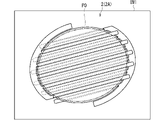
- 1 is a plan view schematically showing an example of the configuration of a plasma source
- FIG. 1 is a cross-sectional view schematically showing an example of the configuration of a plasma source
- FIG. 3 is a diagram schematically showing an example of a configuration of a processing unit according to the first embodiment
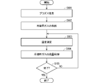
- FIG. 4 is a flow chart illustrating the operation of the first example of the plasma generator;
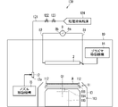
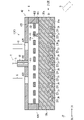
- FIG. 4 is a side cross-sectional view schematically showing the configuration of the first example of the plasma generator and the first modification of the cooling gas supply section in the first embodiment;
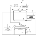
- FIG. 10 is a side cross-sectional view schematically showing the configuration of a second example of the plasma generator and a second modification of the cooling gas supply section;
- FIG. 4 is a cross-sectional view schematically showing an example of the configuration of a flow path forming member;
- FIG. 2 is a cross-sectional view schematically showing an example of the configuration of a substrate;
- FIG. 11 is a side cross-sectional view schematically illustrating the configuration of a third example of the plasma generator and the cooling gas supply section;
- FIG. 4 is a plan view schematically showing an example of the configuration of another plasma source;
- FIG. 4 is a cross-sectional view schematically showing an example of the configuration of another plasma source;
- FIG. 11 is a side cross-sectional view schematically showing a fourth example of the plasma generator and a second modification of the configuration of the cooling gas supply section; It is a figure which shows roughly an example of a structure of the processing unit (substrate processing apparatus) in 2nd Embodiment.
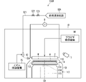
- FIG. 11 is a side cross-sectional view schematically showing the configuration of a fifth example of the plasma generator; It is a figure which shows an example of image data typically.
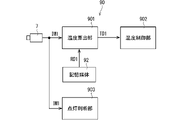
- FIG. 10 is a functional block diagram schematically showing an example of a functional internal configuration of a control unit according to the second embodiment;
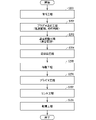
- FIG. 9 is a flow chart showing an example of the operation of a processing unit in the second embodiment;
- 4 is a flow chart showing an example of the operation of a plasma lighting process;
- FIG. 10 is a diagram schematically showing an example of a state in a liquid supply process of a processing unit in the second embodiment; It is a figure which shows roughly an example of the state in the plasma process of the processing unit in 2nd Embodiment.
- FIG. 10 is a side cross-sectional view schematically showing an example of the configuration of another plasma source; It is a figure which shows roughly an example of a structure of the substrate processing apparatus which is an example of a processing unit. It is a block diagram which shows the relationship of the connection of a control part and a substrate processing apparatus. It is the schematic which shows the structure in XY plane view of the plasma generator in 3rd Embodiment.
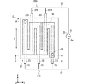
- FIG. 32 is a schematic cross-sectional view showing the EE cross section of FIG. 31; It is a figure which shows typically the arrangement
- FIG. 3 is a flowchart showing a substrate processing process by the substrate processing apparatus; It is the schematic which shows the structure in XY plane view of the plasma generator in 4th Embodiment.
- FIG. 37 is a schematic cross-sectional view showing the FF cross section of FIG. 36; It is a figure which shows typically the arrangement
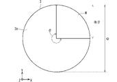
- FIG. 4 is a schematic plan view showing an example of the shape of the first main surface of the dielectric in XY plan view; FIG.
- FIG. 4 is a schematic plan view showing an example of the shape of the first main surface of the dielectric in XY plan view;
- FIG. 4 is a schematic plan view showing an example of the shape of the first main surface of the dielectric in XY plan view;
- FIG. 4 is a schematic plan view showing an example of the shape of the first main surface of the dielectric in XY plan view;
- Each drawing is appropriately labeled with XYZ orthogonal coordinate axes (right-handed system) for explaining directions.
- the Z direction on the coordinate axis indicates the vertical direction
- the XY plane is the horizontal plane.
- one side in the X direction may be called the +X side, and the other side may be called the -X side.
- the +Z side indicates the vertical upper side.
- FIG. 1 is a plan view schematically showing an example of the overall configuration of a substrate processing system 100 to which a plasma generator is applied.
- the substrate processing system 100 is a single wafer processing apparatus that processes substrates W to be processed one by one.
- the substrate W is a semiconductor substrate called a wafer, for example, and has a disk shape.
- the substrate W includes a photomask glass substrate, a liquid crystal display glass substrate, a plasma display glass substrate, a FED (Field Emission Display) substrate, an optical disk substrate, a magnetic disk substrate, and a magneto-optical substrate.
- Various substrates such as disk substrates can be applied.
- the shape of the substrate is not limited to a disk shape, and various shapes such as a rectangular plate shape can be adopted.
- the substrate processing system 100 includes a load port 101 , an indexer robot 110 , a main transfer robot 120 , one or more processing units 130 and a controller 90 .
- the processing units 130 are for processing the substrate W, and at least one of them functions as a substrate processing apparatus which will be detailed later.
- a plurality of load ports 101 are arranged side by side along one horizontal direction. Each load port 101 is an interface section for loading/unloading the substrate W into/from the substrate processing system 100 .
- a carrier C containing substrates W is loaded into each load port 101 from the outside.
- Each load port 101 holds the loaded carrier C.
- the load port 101 can be regarded as a container holding mechanism that holds a plurality of carriers C.
- As the carrier C a FOUP (Front Opening Unified Pod) that houses the substrate W in a sealed space, a SMIF (Standard Mechanical Inter Face) pod, or an OC (Open Cassette) that exposes the substrate W to the outside air may be adopted.
- FOUP Front Opening Unified Pod
- SMIF Standard Mechanical Inter Face
- OC Open Cassette
- the indexer robot 110 is a transport robot that transports the substrate W between each load port 101 (more specifically, the carrier C held by the load port 101) and the main transport robot 120.
- the indexer robot 110 can move along the direction in which the load ports 101 are arranged, and can stop at a position facing each carrier C. As shown in FIG.
- the indexer robot 110 can perform an operation of picking up a substrate W from each carrier C and an operation of transferring a substrate W to each carrier C. As shown in FIG.
- the main transport robot 120 is a transport robot that transports substrates W between the indexer robot 110 and each processing unit 130, and is also called a center robot.
- the main transport robot 120 can perform an operation of receiving the substrate W from the indexer robot 110 and an operation of transferring the substrate W to the indexer robot 110 . Further, the main transport robot 120 can perform an operation of loading the substrate W into each processing unit 130 and an operation of unloading the substrate W from each processing unit 130 .
- the indexer robot 110 and the main transport robot 120 function as a transport mechanism that transports the substrate W between each of the processing units 130 and the load port 101 .
- the substrate platform 140 may intervene in transferring the substrate W between the indexer robot 110 and the main transport robot 120 .
- the substrate mounting part 140 can be regarded as part of the transport mechanism.
- 12 processing units 130 are arranged in the substrate processing system 100 .
- four towers each including three vertically stacked processing units 130 are provided so as to surround the main transfer robot 120 .
- the main transfer robot 120 is provided so as to be surrounded by four towers.
- one of the three-tiered processing units 130 is schematically shown. Note that the number of processing units 130 in the substrate processing system 100 is not limited to twelve, and may be changed as appropriate.
- the main transport robot 120 carries unprocessed substrates W received from the indexer robot 110 into each processing unit 130 .
- Each processing unit 130 processes a substrate W.
- FIG. Further, the main transport robot 120 unloads the processed substrate W from each processing unit 130 and passes it to the indexer robot 110 .
- an unprocessed substrate W is taken out from the carrier C by the indexer robot 110 and transferred to the main transport robot 120 via the substrate platform 140, for example.
- the main transport robot 120 carries this unprocessed substrate W into the processing unit 130 .
- the processing unit 130 performs processing on the substrate W.
- FIG. The processed substrate W is taken out from the processing unit 130 by the main transport robot 120, passed through another processing unit 130 as necessary, and then transferred to the indexer robot 110 via the substrate platform 140, for example.
- the indexer robot 110 loads the processed substrate W into the carrier C. As shown in FIG.
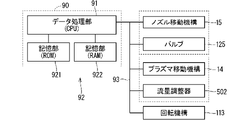
- FIG. 2 is a functional block diagram schematically showing an example of the internal configuration of the control section 90.
- the control unit 90 is an electronic circuit and has, for example, a data processing unit 91 and a storage unit 92 .
- the data processing section 91 and the storage section 92 are interconnected via a bus 93 .
- the data processing unit 91 may be an arithmetic processing device such as a CPU (Central Processor Unit).
- the storage unit 92 has a non-temporary storage unit (eg, ROM (Read Only Memory), rewritable memory, or hard disk) 921 and a temporary storage unit (eg, RAM (Random Access Memory)) 922. good.
- the non-temporary storage unit 921 may store, for example, a program that defines processing to be executed by the control unit 90 .
- the control unit 90 can execute the processing specified in the program.
- part or all of the processing executed by the control unit 90 may be executed by hardware.
- FIG. 2 an aspect in which the indexer robot 110, the main transport robot 120 and the processing unit 130 are connected to the bus 93 is schematically shown as an example.
- control unit 90 may have a main control unit and a plurality of local control units.
- a main controller controls the entire substrate processing system 100
- a local controller is provided for each processing unit 130 .
- the local control section is provided so as to be able to communicate with the main control section, and controls the processing unit 130 based on instructions from the main control section.
- Each of the main control unit and the local control unit has a data processing unit 91 and a storage unit 92, as in FIG. 2, for example.
- FIG. 3 is a diagram schematically showing an example of the configuration of the processing unit (corresponding to the substrate processing apparatus) 130. As shown in FIG. It is not necessary for all the processing units 130 belonging to the substrate processing system 100 to have the configuration shown in FIG. 3, and at least one processing unit 130 may have the configuration.
- the processing unit 130 illustrated in FIG. 3 is an apparatus that performs processing on the substrate W using plasma.
- "Treatment using plasma” does not have to be particularly limited, but includes organic substance removal treatment as a specific example.
- the organic substance removal process is a process for removing organic substances formed on the main surface of the substrate W.
- the organic material is, for example, resist.
- the organic matter removing treatment can also be said to be a resist removing treatment.
- This resist film is used, for example, as an implantation mask for an ion implantation process.
- the substrate W is, for example, a semiconductor substrate and has a disk shape. Although the size of the substrate W is not particularly limited, its diameter is, for example, about 300 mm.
- the processing unit 130 includes the plasma source 2, the holding mechanism 11, the nozzle 12 and the guard 13.
- the processing unit 130 has a chamber 10, for example.
- Chamber 10 houses plasma source 2 , holding mechanism 11 , nozzle 12 and guard 13 .
- the substrate can be processed in a desired atmosphere.
- the holding mechanism 11 holds the substrate W in a horizontal posture.
- the horizontal posture referred to here is a posture in which the thickness direction of the substrate W is along the vertical direction.
- the substrate W is held by the holding mechanism 11 with the back surface facing downward.
- the “rear surface” of the substrate W is, for example, the main surface of the substrate W on which devices are not formed.
- the holding mechanism 11 includes a stage 111 and multiple supports 112.
- the stage 111 has a disk shape and is provided below the substrate W in the vertical direction.
- the stage 111 is provided in such a posture that its thickness direction is along the vertical direction.
- the plurality of support portions 112 are, for example, chuck pins, are fixed to the upper surface of the stage 111, and are erected, for example.
- the supporting portion 112 grips the peripheral edge of the substrate W.
- the plurality of supporting portions 112 support the substrate W from the back side of the substrate W.
- the plurality of support portions 112 are arranged, for example, in a circular shape when viewed in the XY plane.
- the holding mechanism 11 does not necessarily have to have the support portion 112 .
- the holding mechanism 11 may suck the substrate W by sucking the back surface of the substrate W.
- FIG. A suction member may be used instead of the support portion 112 .
- the attracting surface of the attracting member has, for example, a circular shape when viewed from the XY plane.
- the diameter of the adsorption member is smaller than the diameter of the substrate W, for example, one-fourth or less of the diameter of the substrate W. As shown in FIG.
- a rotating mechanism 113 is provided within the chamber 10 .
- the rotation mechanism 113 rotates the holding mechanism 11 (more specifically, the stage 111 that fixes the support portion 112) around the rotation axis Q1.
- the substrate W held by the holding mechanism 11 also rotates around the rotation axis Q1.
- the rotation axis Q1 is a virtual axis that passes through the central portion of the substrate W and extends along the vertical direction. It may be understood that the holding mechanism 11 includes the rotating mechanism 113 . In this case, the holding mechanism 11 rotates the substrate W around the rotation axis Q1.
- the rotating mechanism 113 includes a shaft 114 and a motor 115, for example.
- Shaft 114 is, for example, a hollow shaft having a cylindrical shape.
- the motor 115 is provided coaxially with the shaft 114 .
- Motor 115 is controlled by control unit 90 .
- the upper end of the shaft 114 is connected to the lower surface of the stage 111 and extends from the lower surface of the stage 111 along the rotation axis Q1.
- Shaft 114 extends upwardly from motor 115 .
- Motor 115 is connected to support 112 via shaft 114 and stage 111 .
- the motor 115 rotates the shaft 114 around the rotation axis Q1 to rotate the stage 111 .
- the substrate W held by the plurality of support portions 112 rotates around the rotation axis Q1.
- Such a holding mechanism 11 can also be called a spin chuck.
- the nozzle 12 is provided inside the chamber 10 and used to supply the processing liquid to the substrate W held by the holding mechanism 11 .
- the nozzle 12 is connected to a processing liquid supply source 124 via a supply pipe 121 . That is, the downstream end of the supply pipe 121 is connected to the nozzle 12 and the upstream end of the supply pipe 121 is connected to the processing liquid supply source 124 .
- the processing liquid supply source 124 includes, for example, a tank (not shown) that stores the processing liquid, and supplies the processing liquid to the supply pipe 121 .
- a chemical liquid and a rinse liquid can be used as the treatment liquid.
- the rinsing liquid is a processing liquid for washing away the chemical liquid on the substrate W.
- an acidic chemical can be used. More specifically, the chemical solution is, for example, hydrochloric acid, hydrofluoric acid, phosphoric acid, nitric acid, sulfuric acid, sulfate, peroxosulfuric acid, peroxosulfate, hydrogen peroxide, tetramethylammonium hydroxide, or a mixture of ammonia and hydrogen peroxide water. one or more of liquid (SC1) and mixed liquid (SC2) of hydrochloric acid and hydrogen peroxide solution.
- the rinse solution is, for example, one or more of deionized water (DIW), isopropyl alcohol (IPA).
- DIW deionized water
- IPA isopropyl alcohol
- a plurality of nozzles 12 may be provided according to the type of treatment liquid.
- the processing liquid from the processing liquid supply source 124 is supplied to the nozzle 12 through the supply pipe 121 and ejected from the ejection port 12 a of the nozzle 12 .
- the flow rate adjusting section 123 adjusts the flow rate of the processing liquid flowing through the supply pipe 121 .
- the flow rate adjusting unit 123 is, for example, a mass flow controller.
- the nozzle 12 is movably provided by a nozzle moving mechanism 15.
- the nozzle moving mechanism 15 moves the nozzle 12 between the first processing position and the first standby position.
- the first processing position is a position where the nozzle 12 discharges the processing liquid toward the main surface of the substrate W (for example, the upper surface: the surface of the substrate W on the +Z side). More specifically, the first processing position is, for example, a position vertically above the substrate W and facing the central portion of the substrate W in the vertical direction.
- the first standby position is a position where the nozzle 12 does not discharge the processing liquid toward the main surface of the substrate W, and is a position further away from the substrate W than the first processing position.
- the first standby position is also a position where the nozzle 12 does not interfere with the transport path of the substrate W by the main transport robot 120 .
- the first standby position is a position radially outside the peripheral edge of the substrate W (outside the peripheral edge of the substrate W in the XY plan view).
- FIG. 3 shows the nozzle 12 stopped at the first standby position.
- FIG. 4 is also a diagram schematically showing an example of the configuration of the processing unit 130, showing the nozzles 12 stopped at the first processing position.
- the nozzle moving mechanism 15 has, for example, a ball screw mechanism or an arm turning mechanism.
- the arm turning mechanism includes an arm, a support column, and a motor (none of which are shown).
- the arm has a horizontally extending rod-like shape, the tip of the arm is connected to the nozzle 12, and the base end of the arm is connected to the support column.
- the support column extends vertically and is rotatable around its central axis.
- the base end of the support column is connected to a motor, and the motor rotates the support column, thereby rotating the arm and moving the nozzle 12 along the central axis of the support column along the circumferential direction.
- a support column is provided so that the first processing position and the first standby position are positioned on the moving path of the nozzle 12 .
- the processing liquid is discharged from the nozzle 12 toward the upper surface of the substrate W during rotation.
- the processing liquid lands on the upper surface of the substrate W, spreads over the upper surface of the substrate W as the substrate W rotates, and scatters outward from the peripheral edge of the substrate W.
- FIG. As a result, a liquid film F (see FIG. 4) of the processing liquid is formed on the upper surface of the substrate W. As shown in FIG.
- the guard 13 has a cylindrical shape surrounding the substrate W held by the holding mechanism 11 .
- the processing liquid scattered from the peripheral edge of the substrate W hits the inner peripheral surface of the guard 13 and flows vertically downward along the inner peripheral surface.
- the processing liquid scattered from the periphery of the substrate W before being irradiated with plasma flows, for example, through a collection pipe (not shown) and is collected in the tank of the processing liquid supply source 124 . According to this, the treatment liquid can be reused.
- the motor 115 is housed in the guard 13.
- Guard 13 protects motor 115 from the external process atmosphere.
- a guard 13 protects the motor 115 from the processing liquid.
- the plasma source 2 is a device that generates plasma and can also be called a plasma reactor.
- the plasma source 2 is provided at a position facing the main surface (for example, the upper surface) of the substrate W held by the holding mechanism 11 in the vertical direction.
- the plasma source 2 is provided vertically above the upper surface of the substrate W.
- the plasma source 2 is connected to a power source 8, and receives power from the power source 8 to turn surrounding gas into plasma.
- the plasma source 2 generates plasma under atmospheric pressure.
- the atmospheric pressure here is, for example, 80% or more of the standard pressure and 120% or less of the standard pressure. An example of a specific configuration of the plasma source 2 will be detailed later.
- the power supply 8 is arranged outside the chamber 10, for example.
- the power supply 8 is controlled by the control section 90 .
- a plasma moving mechanism 14 may be provided as illustrated in FIGS.
- the plasma moving mechanism 14 relatively moves the plasma source 2 with respect to the substrate W held by the holding mechanism 11 .
- the plasma moving mechanism 14 reciprocates the plasma source 2 between the second processing position and the second standby position.
- the second processing position is a position where the substrate W is processed using plasma from the plasma source 2 .
- the distance between the plasma source 2 and the upper surface of the substrate W is, for example, several millimeters.
- FIG. 5 is also a diagram schematically showing an example of the configuration of the processing unit 130, showing the plasma source 2 stopped at the second processing position.
- the second standby position is a position when the substrate W is not processed using plasma, and is a position further away from the substrate W than the second processing position.
- the second standby position is also a position where the plasma source 2 does not interfere with the transport path of the substrate W by the main transport robot 120 .
- the second standby position is a position vertically above the second processing position. In this case, the plasma moving mechanism 14 raises and lowers the plasma source 2 along the vertical direction. 3 and 4 show the plasma source 2 stopped at the second standby position.
- the plasma moving mechanism 14 has a moving mechanism such as a ball screw mechanism or an air cylinder.
- the plasma moving mechanism 14 includes, for example, an electric linear motor or a ball screw and electric rotary motor. Also, the plasma moving mechanism 14 moves up and down, for example, in the Z-axis direction.
- the plasma moving mechanism 14 has the same configuration as the nozzle moving mechanism 15, and moves in the XY plane direction between a position facing the upper surface of the substrate W and a position not facing the upper surface of the substrate W. good too.
- the plasma source 2 can move from the second waiting position to the second processing position while the nozzle 12 is retracted to the first waiting position.
- the valve 122 is closed and the nozzle moving mechanism 15 moves the nozzle 12.
- the power source 8 outputs voltage to the plasma source 2 while the plasma source 2 is positioned at the second standby position. Thereby, the plasma source 2 generates plasma at a position farther from the substrate W than the second processing position.
- the plasma source 2 generates plasma in parallel with the nozzle 12 supplying the liquid film F of the processing liquid onto the upper surface of the substrate W at the first processing position. can be reduced.
- the plasma moving mechanism 14 moves the plasma source 2 from the second standby position to the second processing position. According to this, since the nozzle 12 does not exist directly above the substrate W, the plasma source 2 can be brought closer to the upper surface of the substrate W. FIG. In other words, the second processing position can be set closer to the substrate W.
- this causes the plasma source 2 to generate plasma toward the processing liquid on the upper surface of the substrate W at a position near the upper surface of the substrate W.
- Various active species are generated with the generation of this plasma.
- plasmatization of air can generate various active species such as oxygen radicals, hydroxyl radicals, and ozone gas. These active species act on the upper surface of the substrate W.
- the active species act on the liquid film F of the processing liquid (sulfuric acid in this case) on the upper surface of the substrate W.
- the reaction between active species and sulfuric acid produces caro's acid with high processing performance (here, oxidizing power).
- Caro's acid is also called peroxomonosulfate.
- the Caro's acid acts on the resist on the substrate W, so that the resist can be quickly oxidized and removed.
- the active species act on the processing liquid on the main surface of the substrate W
- the processing performance of the processing liquid can be improved. Therefore, the substrate W can be processed quickly.
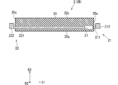
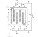
- FIG. 6 is a plan view schematically showing an example of the configuration of the plasma source 2A.
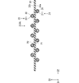
- FIG. 7 is a cross-sectional view schematically showing an example of the configuration of the plasma source 2A, showing the cross section A of FIG.
- Plasma source 2A is an example of plasma source 2 .
- the plasma source 2A is a planar plasma source and includes a first electrode portion 21 and a second electrode portion 22.
- FIG. 6 is a plan view schematically showing an example of the configuration of the plasma source 2A.
- FIG. 7 is a cross-sectional view schematically showing an example of the configuration of the plasma source 2A, showing the cross section A of FIG.
- Plasma source 2A is an example of plasma source 2 .
- the plasma source 2A is a planar plasma source and includes a first electrode portion 21 and a second electrode portion 22.
- the first electrode section 21 includes a plurality of first linear electrodes 211 and a first collective electrode 212
- the second electrode section 22 includes a plurality of second linear electrodes 221 and a second and a collection electrode 222 .
- the first linear electrode 211 is made of a conductive material such as a metal material (eg, tungsten) and has a rod-like shape (eg, a cylindrical shape) extending along the longitudinal direction D1.
- the plurality of first linear electrodes 211 are arranged side by side in an arrangement direction D2 perpendicular to the longitudinal direction D1, and ideally parallel to each other.
- the first collective electrode 212 is made of a conductive material such as a metal material (for example, aluminum), and connects ends (base ends) on one side of the plurality of first linear electrodes 211 in the longitudinal direction D1.
- the first collective electrode 212 has an arcuate flat plate shape that bulges to one side in the longitudinal direction D1.
- a plurality of first linear electrodes 211 extend from the first collective electrode 212 toward the other side in the longitudinal direction D1.
- the second linear electrode 221 is made of a conductive material such as a metal material (eg, tungsten) and has a rod-like shape (eg, a cylindrical shape) extending along the longitudinal direction D1.
- the plurality of second linear electrodes 221 are arranged side by side in the arrangement direction D2 and ideally parallel to each other.
- Each of the second linear electrodes 221 is two of the plurality of first linear electrodes 211 adjacent to each other in a plan view (that is, when viewed along a direction D3 perpendicular to the longitudinal direction D1 and the arrangement direction D2). is set between In the example of FIG. 6, the first linear electrodes 211 and the second linear electrodes 221 are alternately arranged in the arrangement direction D2 in plan view.
- Each of the first linear electrodes 211 does not face the second linear electrodes 221 in the direction D3.
- the second collective electrode 222 is made of a conductive material such as a metal material (for example, aluminum) and connects the ends (basal ends) of the plurality of second linear electrodes 221 on the other side in the longitudinal direction D1.
- the second collective electrode 222 bulges in the opposite direction to the first collective electrode 212 and has an arcuate plate shape with approximately the same diameter as the first collective electrode 212 .
- a plurality of second linear electrodes 221 extend from the second collective electrode 222 toward one side in the longitudinal direction D1.
- each first linear electrode 211 is covered with the first dielectric 31.
- the plurality of first dielectrics 31 are made of a dielectric material such as quartz or ceramics.
- each first dielectric 31 has a tubular shape extending along the longitudinal direction D1, and the first linear electrode 211 is inserted into the first dielectric 31 along the longitudinal direction D1.
- each second linear electrode 221 is covered with the second dielectric 32.
- the plurality of second dielectrics 32 are made of a dielectric material such as quartz or ceramics.
- each second dielectric 32 has a tubular shape extending along the longitudinal direction D1, and the second linear electrode 221 is inserted into the second dielectric 32 along the longitudinal direction D1.
- a partition member 33 is provided in the plasma source 2A.
- the partition member 33 is a dielectric made of a dielectric material such as quartz or ceramics.
- the partition member 33 has a plate-like shape.
- the partition member 33 has a main surface 33a on one side and a main surface 33b on the other side.
- the main surfaces 33 a and 33 b face each other in the thickness direction of the partition member 33 .
- the partition member 33 is provided so that its thickness direction is along the direction D3.
- the main surface 33a and the main surface 33b of the partition member 33 have a circular shape in plan view.
- the thickness of the partition member 33 (the distance between the main surface 33a and the main surface 33b) is set at, for example, several hundred ⁇ m (eg, 300 to 500 ⁇ m).
- the first electrode portion 21 and the first dielectric 31 are provided on the main surface 33a side of the partition member 33, and the second electrode portion 22 and the second dielectric 32 are provided on the main surface 33b side of the partition member 33.
- the first dielectric 31 is provided under the main surface 33 a of the partition member 33
- the second dielectric 32 is provided on the main surface 33 b of the partition member 33 .
- the plasma source 2A is provided in the processing unit 130 in such a posture that the main surface 33a faces the processing target (here, the substrate W). Specifically, the plasma source 2A is provided in such a posture that the direction D3 is along the vertical direction and the main surface 33a faces the upper surface of the substrate W. As shown in FIG. This plasma source 2A faces the substrate W in the vertical direction.
- the first electrode portion 21 and the second electrode portion 22 are electrically connected to the power source 8 for plasma.
- the power supply 8 has a switching power supply circuit (not shown) such as an inverter circuit, and outputs voltage for plasma between the first electrode portion 21 and the second electrode portion 22 .
- the first collective electrode 212 of the first electrode section 21 is electrically connected to the first output terminal 8a of the power source 8 via the wiring 81
- the second collective electrode 222 of the second electrode section 22 is electrically connected to the power source via the wiring 82.
- 8 is electrically connected to the second output end 8b.
- the power supply 8 outputs a voltage for plasma, eg, a high frequency voltage, to the first output end 8a and the second output end 8b.
- the power supply 8 is, for example, a pulse power supply, and may output a high-frequency voltage between the first electrode section 21 and the second electrode section 22 during the ON period in each of a plurality of cycles. As a result, the plasma is lit mainly during the ON period.
- the output of this power supply 8 is controlled by a control section 90 . Therefore, it can be said that the plasma source 2A is controlled by the controller 90 .
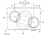
- a plasma electric field is generated between the first linear electrode 211 and the second linear electrode 221 by the power supply 8 outputting a voltage between the first electrode portion 21 and the second electrode portion 22 .
- the gas around the first linear electrode 211 and the second linear electrode 221 turns into plasma according to the electric field.
- the gas between the first linear electrode 211 and the second linear electrode 221 is plasmatized to generate plasma P1 and plasma P2, respectively (see FIG. 6). reference).
- the power source 8 applies a voltage to the extent that the gas becomes plasma between the first electrode portion 21 and the second electrode portion 22 .
- the voltage is, for example, a high frequency voltage of about several tens of kV and several tens of kHz.
- the frequency here is, for example, the reciprocal of the period, and is hereinafter referred to as pulse frequency.
- the first linear electrodes 211 and the second linear electrodes 221 both extending along the horizontal longitudinal direction D1 are arranged alternately in the horizontal arrangement direction D2. be. Therefore, the plasma source 2A can generate plasma over a wide range in plan view.
- the contours of the regions where the plasmas P1 and P2 are generated are schematically indicated by two-dot chain lines.
- the plasma generation region can also be said to be a light emitting region where the plasma emits light.
- the plasma source 2 (the plasma source 2A is an example) receives power and plasma is generated around it, the temperature of the plasma source 2 rises due to the plasma generation. If the temperature of the plasma source 2 rises more than necessary, various problems may occur. For example, problems such as an increase in the manufacturing cost of the plasma source 2 due to improved heat resistance, thermal damage to the substrate W to be processed, or contamination of peripheral members due to boiling of the processing liquid on the main surface of the substrate W. can occur.
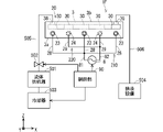
- FIG. 8 is a diagram schematically showing an example of the configuration of the processing unit 130A.
- Processing unit 130A is an example of processing unit 130 described above. Descriptions of elements of the processing unit 130A that have already been described for the processing unit 130 are omitted.
- the processing unit 130A includes the plasma generator 1 and the cooling gas supply unit 5, which were not specifically shown in the processing unit 130.
- a plasma generator 1 includes a plasma source 2 and a cooling member 4 .
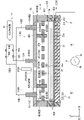
- FIG. 9 is a side sectional view schematically showing an example of the configuration of the plasma generator 1A.
- the plasma generator 1A is a first example of the plasma generator 1.
- FIG. A plasma generator 1A includes a plasma source 2A, a cooling member 4, and a temperature measuring section 6. As shown in FIG. FIG. 9 shows a cross section at a position corresponding to the BB cross section of FIG.
- the cooling member 4 has an air supply port 411 for supplying cooling gas to the plasma source 2A.
- the air supply port 411 faces the plasma source 2A with a gap therebetween.
- the air supply port 411 is provided at the downstream end of the air supply path 412 , and the cooling gas is supplied from the cooling gas supply unit 5 to the air supply path 412 .
- the cooling gas includes at least one of nitrogen gas and air, for example. The cooling gas flows through the air supply path 412 toward the air supply port 411 and flows out from the air supply port 411 .
- the cooling gas flowing out from the air supply port 411 flows toward the plasma source 2A and is supplied to the plasma source 2A.
- the plasma source 2A can be air-cooled. Thereby, the temperature rise of the plasma source 2A can be mitigated.
- the temperature of the plasma source 2A drops too much, the plasma can be extinguished.
- the temperature measurement unit 6 measures the temperature of the plasma source 2A. Temperature measurement unit 6 outputs an electrical signal indicating the measurement result to control unit 90 .
- the control unit 90 controls the flow rate of the cooling gas supplied to the plasma source 2A based on the temperature measured by the temperature measurement unit 6.
- the plasma source 2A can be air-cooled while monitoring the temperature of the plasma source 2A. Therefore, the temperature of the plasma source 2A can be controlled with high precision. Therefore, it is possible to more reliably suppress the above problems due to temperature rise and temperature drop.
- plasma is generated over the entire plasma source 2A while the plasma source 2A is positioned at the second standby position, which is further from the substrate W than the second processing position. Then, the temperature of the plasma source 2A is cooled to a temperature suitable for processing the substrate W. FIG. After that, the plasma source 2A is moved from the second waiting position to the second processing position. By doing so, damage to the substrate W and peripheral members due to high heat caused by plasma generation can be suppressed compared to the case where the plasma is generated at a position near the upper surface of the substrate W. Further, the upper surface of the substrate W can be uniformly processed by moving the plasma source 2A to the second processing position after plasma is generated over the entire plasma source 2A.
- the partition member 33 partitions the first space on the main surface 33a side and the second space on the main surface 33b side.
- the first space will be referred to as a processing space
- the second space on the opposite side of the partition member 33 as the processing space will also be referred to as a cooling space.
- the main surface 33a of the partition member 33 is the surface in contact with the processing space
- the main surface 33b of the partition member 33 is the surface in contact with the cooling space.
- the principal surface 33a is also referred to as the processing surface 33a
- the principal surface 33b is also referred to as the cooling surface 33b.
- a holding member 34 may be provided for the plasma source 2A. 8, the illustration of the holding member 34 is omitted in order to avoid complication of the drawing.
- the holding member 34 is made of, for example, an insulating material such as fluorine-based resin, and holds the first electrode portion 21, the second electrode portion 22, the first dielectric 31, the second dielectric 32, and the partition member 33 integrally.
- the holding member 34 has a ring shape having substantially the same diameter as the first collective electrode 212 and the second collective electrode 222 in plan view, and sandwiches the first collective electrode 212 and the second collective electrode 222 in the direction D3. .
- the tip of the first dielectric 31 is held by the holding member 34. Specifically, the tip of the first dielectric 31 is embedded in the holding member 34 . Therefore, both ends of the portion composed of the first linear electrode 211 and the first dielectric 31 are held by the holding member 34 . This allows the portion to be held from both ends.
- the tip of the second dielectric 32 is also held by the holding member 34 . Therefore, the holding member 34 can also hold the portion composed of the second linear electrode 221 and the second dielectric 32 from both ends thereof.
- cooling member 4 has an air supply port 411 through which cooling gas flows.
- the air supply port 411 is provided in the cooling space. That is, the air supply port 411 is provided on the opposite side of the partition member 33 to the processing target (here, the substrate W).
- the air supply port 411 is provided at a position facing the cooling surface 33b of the partition member 33 in the direction D3.
- the air supply port 411 opens toward the cooling surface 33 b of the partition member 33 . More specifically, the opening direction of the air supply port 411 is the direction along the direction D3 perpendicular to the cooling surface 33b.
- the cooling member 4 includes an air supply pipe 41 provided in the cooling space, and the downstream end of the air supply passage 412 inside the air supply pipe 41 corresponds to the air supply port 411 .
- the cooling gas flowing out from the air supply port 411 of the air supply pipe 41 flows toward the plasma source 2A.
- a cooling gas is supplied from the cooling gas supply unit 5 to the air supply pipe 41 (see also FIG. 8).
- the cooling gas supply section 5 includes an air supply pipe 51 , a valve 52 and a flow rate adjustment section 53 .
- Air supply pipe 51 connects air supply pipe 41 and gas supply source 54 .
- the downstream end of the air supply pipe 51 is connected to the air supply pipe 41 and the upstream end of the air supply pipe 51 is connected to the gas supply source 54 .
- the air supply pipe 41 and the air supply pipe 51 may be different parts of one pipe.
- a gas supply source 54 supplies cooling gas to the air supply pipe 51 .
- the cooling gas is, for example, at least one of nitrogen gas and air.
- a valve 52 and a flow control unit 53 are interposed in the air supply pipe 51 .
- Valve 52 is controlled by controller 90 .
- the cooling gas from the gas supply source 54 is supplied to the air supply pipe 41 through the air supply pipe 51 and flows out from the air supply port 411 .
- the cooling gas flowing out from the air supply port 411 flows toward the plasma source 2A and cools the plasma source 2A.
- the supply of the cooling gas is stopped by closing the valve 52 .
- the flow rate adjusting section 53 is controlled by the control section 90 and adjusts the flow rate of the cooling gas flowing through the air supply pipe 51 .
- the flow rate adjusting unit 53 is, for example, a mass flow controller.
- the cooling member 4 further includes a flow path forming member 42.
- the flow path forming member 42 forms the gas space 40 through which the cooling gas flowing out from the air supply port 411 flows.
- the flow path forming member 42 is provided on the cooling space side with respect to the partition member 33 and is connected to the periphery of the plasma source 2A to form the gas space 40 together with the plasma source 2A.
- the flow path forming member 42 includes a cover portion 421 and side walls 422 .
- the cover part 421 has a plate-like shape, for example, and is provided in a posture in which the thickness direction thereof is along the direction D3.
- the cover part 421 has, for example, a disk shape with substantially the same diameter as the holding member 34, and is provided at a position facing the plasma source 2A in the direction D3.
- a through hole through which the air supply pipe 41 is arranged is formed in the central portion of the cover portion 421 .
- the air supply pipe 41 and the cover portion 421 are connected to each other.
- An air supply port 411 of the air supply pipe 41 opens in the gas space 40 .
- the side wall 422 has a cylindrical shape erected on the peripheral edge of the cover portion 421 and extends toward the holding member 34 side.
- the inner peripheral surface of the side wall 422 is located outside the tip of the first linear electrode 211 and the tip of the second linear electrode 221 in plan view.
- the sidewall 422 overlaps the holding member 34 in the direction D3 and is connected to the holding member 34.
- the flow path forming member 42 may be configured integrally with the holding member 34, or may be configured by combining a plurality of members.
- the gas space 40 surrounded by the cover portion 421, the side wall 422 and the plasma source 2A. Since the holding member 34 is also a part of the member forming the gas space 40 , it can be said that it belongs to the flow path forming member 42 . In other words, it is also possible to grasp the portion composed of the side wall 422 and the holding member 34 as the side wall 423 of the flow path forming member 42 .
- An exhaust path 424 is provided in the flow path forming member 42 .
- the exhaust path 424 is provided in the side wall 423 of the flow path forming member 42 (holding member 34 in the drawing).
- the exhaust path 424 is, for example, a through hole connecting the inner peripheral surface and the outer peripheral surface of the holding member 34 .
- the cooling gas flowing out from the air supply port 411 flows toward the plasma source 2A, collides with the plasma source 2A, flows along the plasma source 2A, and is discharged to the outside through the exhaust path 424.
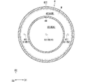
- a plurality of exhaust paths 424 may be provided in the flow path forming member 42 as illustrated in FIG.
- the plurality of exhaust paths 424 are provided at different positions in the circumferential direction of the side wall 423, and as a more specific example, are provided at regular intervals.
- exhaust path 424 does not necessarily have to be formed in the holding member 34 , and may be formed in the side wall 422 or at the boundary between the side wall 422 and the holding member 34 , for example.
- a straightening member 43 is provided between the air supply port 411 of the air supply pipe 41 and the plasma source 2A.
- the straightening member 43 is a member for straightening the cooling gas flowing out from the air supply port 411 and supplying the straightened cooling gas to the plasma source 2A.
- the rectifying member 43 has, for example, a plate-like shape, and is provided in a posture such that its thickness direction is along the direction D3.
- a plurality of through holes 43 a are formed in the rectifying member 43 .
- the through hole 43a penetrates the rectifying member 43 in the direction D3.
- the plurality of through holes 43a are two-dimensionally arranged in plan view, for example, in a matrix.
- the straightening member 43 has a disk shape, and its peripheral edge is fixed to the inner peripheral surface of the side wall 422 of the flow path forming member 42 .
- the cooling gas flowing out from the air supply port 411 is rectified by passing through the plurality of through holes 43a of the rectifying member 43, and the rectified cooling gas flows toward the plasma source 2A. .
- the cooling gas flows toward the surroundings along the plasma source 2A and is discharged to the outside through a plurality of exhaust paths 424.
- FIG. The exhaust path 424 is preferably provided downstream of the straightening member 43 .
- temperature measurement unit 6 measures the temperature of plasma source 2A.
- the temperature measurement unit 6 is a temperature sensor that measures temperature in a non-contact manner, and as a specific example, it is an infrared sensor that detects infrared rays.
- the sensor includes a radiation thermometer.
- the temperature measurement unit 6 is provided on the cooling space side with respect to the plasma source 2A. Specifically, the temperature measurement unit 6 is provided on the opposite side of the flow path forming member 42 from the plasma source 2A.
- a measurement window 425 is formed in the flow path forming member 42 , and the temperature measurement unit 6 measures the temperature of the plasma source 2A through the measurement window 425 .
- the measurement window 425 is formed in the cover portion 421 of the flow path forming member 42 .
- the measurement window 425 penetrates the cover portion 421 along the direction D3 and faces the plasma source 2A in the direction D3.
- the measurement window 425 may be, for example, a translucent member.
- This light-transmitting member is made of a light-transmitting material (for example, glass) having a high infrared transmittance (for example, 60% or more, preferably 90% or more).
- the measurement window 425 is formed at a position facing the through hole 43a of the rectifying member 43 in the direction D3.
- the measurement window 425 may be provided at a position facing the rectifying member 43 .
- the temperature measurement unit 6 detects the infrared rays and outputs an electric signal indicating the detection result to the control unit 90 as a temperature measurement value.
- a plurality of temperature measurement units 6 are provided.
- the plurality of temperature measurement units 6 may be provided, for example, at substantially equal intervals in the circumferential direction around the air supply pipe 41 in a plan view.
- a plurality of measurement windows 425 are formed in the cover portion 421 so as to correspond to the plurality of temperature measurement portions 6 .
- a plurality of temperature measurement units 6 measure the temperature of the plasma source 2A at mutually different positions in plan view.
- the control unit 90 may calculate the measured temperature of the plasma source 2A based on the temperatures measured by the plurality of temperature measurement units 6. FIG. For example, the control unit 90 may calculate an average value of a plurality of measured temperatures as the measured temperature.
- the temperature measuring part 6 and the cooling member 4 should be moved integrally with the plasma source 2A. That is, the plasma moving mechanism 14 may move the plasma source 2A, the cooling member 4 and the temperature measuring section 6 together. According to this, the cooling member 4 can cool the plasma source 2A regardless of the position of the plasma source 2A, and the temperature measuring unit 6 can measure the temperature of the plasma source 2A regardless of the position of the plasma source 2A. can be done.
- the translucent member (measurement window 425) is provided in a portion of the cover portion 421 in the above example, the entire cover portion 421 may be formed of a translucent material.
- the rectifying member 43 is also made of a translucent material, the infrared rays from the plasma source 2A can pass through the rectifying member 43 and the cover portion 421, so that the degree of freedom of the installation position of the temperature measuring portion 6 can be improved.
- FIG. 10 is a flow chart schematically showing an example of the operation of the plasma generator 1A.
- the controller 90 controls the power source 8 to generate plasmas P1 and P2 around the plasma source 2A (step S101). Specifically, the power supply 8 outputs a plasma voltage (for example, a high frequency voltage) to the plasma source 2A under the control of the controller 90 . As a result, an electric field for plasma is generated between the first linear electrode 211 and the second linear electrode 221, and the electric field acts on the gas to generate plasmas P1 and P2.
- the plasma source 2A generates plasmas P1 and P2 until the processing ends.
- the plasma source 2A generates plasmas P1 and P2 at the second processing position, thereby supplying various active species caused by the plasma P1 to the processing liquid on the substrate W. can do. Thereby, as described above, the resist on the substrate W can be removed more quickly.
- control unit 90 opens the valve 52 to supply the cooling gas to the plasma source 2A (step S102).
- the cooling gas is supplied from the gas supply source 54 to the air supply pipe 41 through the air supply pipe 51 and flows out from the air supply port 411 .
- the cooling gas flowing out from the air supply port 411 is rectified through the rectifying member 43 in the gas space 40, and the rectified cooling gas is supplied to the plasma source 2A.
- the cooling gas that has collided with the plasma source 2A flows outward along the plasma source 2A and is exhausted to the outside through the exhaust path 424 .
- the temperature measurement unit 6 measures the temperature of the plasma source 2A (step S103).
- control unit 90 controls the flow rate adjustment unit 53 based on the measured temperature measured by the temperature measurement unit 6 to control the flow rate of the cooling gas supplied to the plasma source 2A (step S104). Therefore, the cooling gas supply unit 5 and the cooling member 4 supply the cooling gas to the plasma source 2A at a flow rate based on the temperature measured by the temperature measurement unit 6 .
- the controller 90 controls the flow rate of the cooling gas when the measured temperature is the first temperature to be higher than the flow rate of the cooling gas when the measured temperature is the second temperature lower than the first temperature. Control the flow rate adjusting unit 53 so as to increase. That is, when the measured temperature is high, the control unit 90 increases the flow rate of the cooling gas to decrease the temperature of the plasma source 2A, and when the measured temperature is low, decreases the flow rate of the cooling gas. Increase the temperature of the plasma source 2A.
- the controller 90 may continuously increase the flow rate of the cooling gas as the measured temperature increases, or may increase it stepwise.
- control unit 90 determines whether or not to end the process (step S105). If the predetermined termination condition is satisfied, the control unit 90 determines to terminate the processing, and if the predetermined termination condition is not satisfied, the control unit 90 determines not to terminate the processing. For example, it may be determined that the end condition is satisfied when a predetermined period of time has passed since the voltage output by the power supply 8 . The predetermined period of time is, for example, sufficient time to remove the resist on the substrate W. As shown in FIG. If the termination condition is not met, step S103 is executed again, and if the termination condition is met, the process is terminated. Specifically, the controller 90 causes the power supply 8 to stop outputting voltage and closes the valve 52 .
- the flow rate of the cooling gas is controlled while monitoring the temperature of the plasma source 2A. Therefore, the temperature of the plasma source 2A can be controlled within a predetermined temperature range with high accuracy.
- the plasma source 2A includes the partition member 33, and the cooling member 4 supplies cooling gas to the plasma source 2A in the cooling space partitioned by the partition member 33. Therefore, the cooling gas is less likely to flow into the processing space, and the plasma P1 between the plasma source 2A and the processing target (here, the substrate W) is less likely to be disturbed. Therefore, the active species caused by the plasma P1 can be supplied to the substrate W more uniformly.
- the air supply port 411 of the cooling member 4 is provided at a position facing the cooling surface 33b of the partition member 33 and opens toward the cooling surface 33b. According to this, the cooling gas flowing out from the air supply port 411 flows toward the partition member 33 along the direction D3, so most of the cooling gas can collide with the plasma source 2A.
- the cooling gas flows along the direction D3 toward the plasma source 2A, so most of it tends to hit the plasma source 2A. Therefore, most of the cooling gas flowing out from the air supply port 411 tends to contribute to the cooling of the plasma source 2A. Therefore, the plasma source 2A can be cooled more effectively.
- the exhaust path 424 is formed in the side wall 423 of the flow path forming member 42 . Therefore, the cooling gas that flows out from the air supply port 411 and collides with the plasma source 2A flows outward along the plasma source 2A and is discharged to the outside through the exhaust path 424 . Since the cooling gas flows along the plasma source 2A after the collision, the plasma source 2A can be cooled more effectively.
- the plurality of exhaust paths 424 are provided on the side wall 423 of the flow path forming member 42 at different positions in the circumferential direction.
- the plurality of exhaust paths 424 are provided at regular intervals. Therefore, the cooling gas more evenly flows radially outward along the plasma source 2 ⁇ /b>A and is discharged to the outside through the plurality of exhaust paths 424 . Therefore, the plasma source 2A can be cooled more uniformly. According to this, the temperature distribution of the plasma source 2A can be made more uniform. Therefore, the distribution of the amount of active species generated by the plasma source 2A can be made more uniform, and the active species can act on the substrate W more uniformly.
- the cooling member 4 includes the straightening member 43 . Therefore, the cooling gas can be more uniformly supplied to the plasma source 2A in plan view. Therefore, the temperature of the plasma source 2A can be controlled more uniformly. In other words, the temperature distribution of the plasma source 2A in plan view can be made more uniform. According to this, the distribution of the amount of active species generated by the plasma source 2A can be made more uniform, and the active species can act on the substrate W more uniformly.
- the temperature measuring section 6 is provided closer to the cooling space than the partition member 33 is.
- the temperature measurement unit 6 is provided on the side opposite to the processing target (here, the substrate W) with respect to the plasma source 2A. According to this, since the temperature measuring part 6 is not provided between the plasma source 2A and the substrate W, movement of the active species toward the substrate W is not hindered.
- the plasma source 2A can be brought closer to the object to be processed. In other words, the second processing position of the plasma generator 1 can be set closer to the substrate W.
- the temperature measuring unit 6 can measure the temperature of the plasma source 2A even when the plasma generator 1 is stopped at the second processing position. Temperature can be controlled with high precision.
- the control unit 90 controls the power source 8 to spread the plasma P1, P1, P1, P1, P1, P1, P1, P1, P1, P1, P1, P1, P1, P1, P1, P1, P1, P1, P1, P1, P1, P1, P1, P1, P1, P1, P1, P1, P1, P1, P1, P1, P1, P1, P1, P1, P1, P1, P1, P1, P1, P1, P1, P1, P1, P1, P1, P1, P1, P1, P1, P1, P1, P1, P1, P1, P1, P1, P1, P1, P1, P1, P1, P1, P1, P1, P1, P1, P1, P1, P1, P1, P1, P1, P1, P1, respectively, respectively, around the plasma source 2A from the plasma source 2A. Generate P2. Then, the plasma source 2A is cooled by the cooling gas so that the temperature of the plasma source 2A reaches a temperature suitable for processing the substrate W. FIG. After that, the plasma source 2A is moved from the second waiting position to the second processing position. By doing so, damage to the substrate
- the temperature measurement unit 6 is provided on the opposite side of the plasma source 2A from the processing target (here, the substrate W) in order to measure the temperature of the plasma source 2A during plasma processing.
- the power source 8 outputs a voltage to the plasma source 2A to generate plasmas P1 and P2. is generated, and the controller 90 controls the flow rate of the cooling gas based on the measured temperature of the plasma source 2A.
- the plasma generator 1 moves to the second processing position and performs plasma processing (supply of active species) on the substrate W. As shown in FIG.
- the temperature measurement unit 6 does not perform temperature measurement, and the cooling gas supply unit 5 supplies the cooling gas at the gas flow rate when the temperature of the plasma source 2A is within a predetermined range at the preparation position. do. This also allows the temperature of the plasma source 2A to be maintained within a predetermined range during plasma processing.
- the temperature measurement unit 6 does not necessarily have to be provided on the side opposite to the substrate W with respect to the plasma source 2A.
- the temperature measurement unit 6 may be provided on the substrate W side with respect to the plasma source 2A.
- the temperature measurement unit 6 may be provided at a position closer to the substrate W than the plasma source 2A and outside the plasma source 2A.
- this temperature measuring section 6 is indicated by a chain double-dashed line. In this case, the temperature measuring section 6 does not need to be moved together with the plasma source 2A, and may be immovably fixed inside the processing unit 130 .
- the temperature measurement unit 6 is an infrared sensor (radiation thermometer) in the above example, it may be a thermo camera, for example.
- Thermo cameras are also called thermography cameras.
- a thermo camera has, for example, a plurality of pixels arranged two-dimensionally. Each pixel receives infrared light and detects its intensity.
- a thermo camera can output an infrared image (so-called thermography).
- the imaging range of the thermo camera may be a part of the plasma source 2A or the whole.
- the control unit 90 can grasp the temperature distribution within the imaging range of the plasma source 2A based on the image captured by the thermo camera.
- the controller 90 may average a plurality of temperatures of the plasma source 2A corresponding to a plurality of pixels to calculate the measured temperature of the plasma source 2A.
- the temperature measurement unit 6 measures the intensity of infrared rays that correlate with temperature, but this is not necessarily the case.
- the temperature measurement unit 6 may measure parameters other than infrared rays that have a positive or negative correlation with temperature.
- the temperature measurement unit 6 may be a sensor that measures the emission intensity of the plasmas P1 and P2. If the type of gas is constant, the higher the temperature, the higher the luminous intensity of the plasma.
- the temperature of the plasma source 2A can be calculated based on the relationship measured in advance.
- the temperature measurement unit 6 may be a camera capable of sensing plasma light (for example, a visible light camera).
- the temperature of the plasma source 2A can be controlled by cooling the plasma source 2A with the cooling gas. Therefore, problems due to temperature rise can be suppressed, and plasma disappearance due to temperature drop can also be suppressed. However, it is difficult to further lower the temperature of the plasma source 2A while maintaining the plasma.
- a first gas and a second gas which is more likely to become plasma than the first gas, are employed.
- the first gas includes at least one of nitrogen gas and air, for example.
- the second gas is, for example, argon gas.
- FIG. 11 is a diagram schematically showing the configuration of a first modification of the plasma generator 1A and the cooling gas supply section 5.
- the air supply pipe 51 of the cooling gas supply unit 5 includes a branch pipe 51a, a branch pipe 51b, and a junction pipe 51c.
- the downstream end of the confluence pipe 51 c corresponds to the downstream end of the air supply pipe 51 and is connected to the air supply pipe 41 .
- the downstream end of the branch pipe 51a is connected to the upstream end of the junction pipe 51c, and the upstream end of the branch pipe 51a is connected to the first gas supply source 54a.
- the first gas supply source 54a supplies the first gas to the branch pipe 51a.
- a valve 52a and a flow rate adjusting portion 53a are interposed in the branch pipe 51a.
- the valve 52a is controlled by the controller 90.
- FIG. By opening the valve 52 a , the first gas from the first gas supply source 54 a is supplied to the air supply pipe 41 through the branch pipe 51 a and the junction pipe 51 c and flows out from the air supply port 411 .
- the first gas flowing out from the air supply port 411 flows toward the plasma source 2A.
- the supply of the first gas is stopped by closing the valve 52a.
- the flow rate adjusting section 53a is controlled by the control section 90 and adjusts the flow rate of the first gas flowing through the branch pipe 51a.
- the flow rate adjusting section 53a is, for example, a
- the downstream end of the branch pipe 51b is connected to the upstream end of the junction pipe 51c, and the upstream end of the branch pipe 51b is connected to the second gas supply source 54b.
- the second gas supply source 54b supplies the second gas to the branch pipe 51b.
- a valve 52b and a flow control portion 53b are interposed in the branch pipe 51b.
- the valve 52b is controlled by the controller 90.
- FIG. By opening the valve 52 b , the second gas from the second gas supply source 54 b is supplied to the air supply pipe 41 through the branch pipe 51 b and the junction pipe 51 c and flows out from the air supply port 411 .
- the second gas flowing out from the air supply port 411 flows toward the plasma source 2A.
- the supply of the second gas is stopped by closing the valve 52b.
- the flow rate adjusting section 53b is controlled by the control section 90 and adjusts the flow rate of the second gas flowing through the branch pipe 51b.
- the flow rate adjusting section 53b is, for example, a mass flow
- the control unit 90 opens the valves 52a and 52b, so that the mixed gas of the first gas and the second gas that is more likely to generate plasma than the first gas is used as the cooling gas. It can be supplied to the plasma source 2A.
- the first gas is mainly used for cooling the plasma source 2A
- the second gas is mainly used for maintaining the plasma P2.
- the control unit 90 controls the flow rate of the cooling gas based on the temperature measured by the temperature measurement unit 6. Specifically, the controller 90 controls the flow rate of the first gas when the measured temperature is the first temperature to be higher than the flow rate of the first gas when the measured temperature is a second temperature lower than the first temperature. Control the flow rate adjusting unit 53a so as to increase. That is, the controller 90 increases the flow rate of the first gas to lower the temperature of the plasma source 2A when the measured temperature is high, and reduces the flow rate of the first gas to lower the temperature of the plasma source 2A when the measured temperature is low. to raise The control unit 90 may continuously increase the flow rate of the first gas as the measured temperature increases, or may increase it stepwise.
- the temperature of the plasma source 2A can be controlled within a predetermined range with high accuracy.
- the plasma source 2A is also supplied with the second gas, which is easily turned into plasma.
- the control unit 90 may control the flow rate adjusting unit 53b so that the flow rate of the second gas becomes a preset constant value.
- the generation of plasmas P1 and P2 can be maintained around the plasma source 2A.
- the second gas is turned into plasma on the cooling space side of the partition member 33, so the plasma P2 can be maintained (see also FIG. 7).
- the applicant confirmed that the plasma P1 is maintained also on the processing space side due to the maintenance of the plasma P2 on the cooling space side.
- the cooling gas As described above, by adopting the mixed gas of the first gas and the second gas, which is more likely to become plasma than the first gas, as the cooling gas, it is possible to both lower the temperature and maintain the plasmas P1 and P2. be able to. In other words, the temperature range in which the plasmas P1 and P2 can be maintained can be widened.
- the flow rate of the second gas does not necessarily have to be controlled constant.
- the control section 90 may also control the flow rate of the second gas based on the measured temperature measured by the temperature measurement section 6 . More specifically, the controller 90 determines that the flow rate of the second gas when the measured temperature is the first temperature is higher than the flow rate of the second gas when the measured temperature is a second temperature lower than the first temperature. You may control the flow volume adjustment part 53b so that it may become small. That is, the controller 90 may decrease the flow rate of the second gas when the measured temperature is high, and increase the flow rate of the second gas when the measured temperature is low.
- the plasmas P1 and P2 can be more reliably maintained by increasing the flow rate of the second gas at low temperatures when the possibility of the plasmas P1 and P2 disappearing is high.
- the consumption of the second gas is reduced at high temperatures when the plasmas P1 and P2 are less likely to disappear. According to this, it is possible to reduce the consumption of the second gas while maintaining the plasmas P1 and P2 at high temperatures.
- the flow rate of the second gas may be zero.
- FIG. 12 is a side sectional view schematically showing a second modification of the plasma generator 1B and the cooling gas supply section 5.
- a plasma generator 1 B is a second example of the plasma generator 1 .
- the plasma generator 1B has the same configuration as the plasma generator 1A described above, except for the configuration of the cooling member 4. As shown in FIG.
- the cooling member 4 has a plurality of air supply ports 411.
- a plurality of air supply ports 411 are provided closer to the cooling space than the partition member 33, and are provided at positions facing the plasma source 2A in the direction D3. Therefore, the plurality of air supply ports 411 face different regions of the plasma source 2A in the direction D3.
- the air supply port 411A is formed at a position facing the central region of the plasma source 2A (specifically, the central region of the partition member 33, corresponding to the second central region) in the direction D3, and the air supply port 411B1 is formed in the plasma source 2A.
- the peripheral region (specifically, the peripheral region of the partition member 33, corresponding to the second peripheral region) is formed at a position facing in the direction D3, and the air supply port 411B2 is opposed to the air supply port 411A. on the opposite side to the peripheral region of the plasma source 2A in the direction D3.
- the cooling member 4 includes three air supply pipes 41A, 41B1, 41B2, and air supply ports 411A, 411B1, 411B2 are formed at the downstream ends of the air supply pipes 41A, 41B1, 41B2, respectively.
- the cooling gas supply unit 5 supplies cooling gas to the air supply pipes 41A, 41B1 and 41B2.
- the air supply pipe 41A is connected to the gas supply source 54 via the air supply pipe 51A.
- a valve 52A and a flow control portion 53a are interposed in the air supply pipe 51A.
- Valve 52A is controlled by controller 90 .
- the cooling gas from the gas supply source 54 is supplied to the air supply pipe 41A through the air supply pipe 51A and flows out from the air supply port 411A.
- the cooling gas flowing out of the air supply port 411A flows toward the central region of the plasma source 2A.
- By closing the valve 52A the supply of the cooling gas from the air supply port 411A is stopped.
- the flow rate adjusting section 53a is controlled by the control section 90 and adjusts the flow rate of the cooling gas flowing through the air supply pipe 51A. In other words, the flow rate adjuster 53a adjusts the flow rate of the cooling gas toward the central region of the plasma source 2A.
- the flow rate adjusting section 53a is, for example, a mass flow controller.
- the air supply pipe 41B1 is connected to the gas supply source 54 via the branch pipe 51B1 and the common pipe 51B3, and the air supply pipe 41B2 is connected to the gas supply source 54 via the branch pipe 51B2 and the common pipe 51B3.
- a valve 52B and a flow rate adjusting section 53B are interposed in the common pipe 51B3.
- Valve 52B is controlled by controller 90 .
- the cooling gas from the gas supply source 54 is supplied to the air supply pipes 41B1 and 41B2, respectively, and flows out from the air supply ports 411B1 and 411B2.
- the cooling gas flowing out from the air supply ports 411B1 and 411B2 flows toward the peripheral region of the plasma source 2A.
- the flow rate adjusting section 53B is controlled by the control section 90 to adjust the flow rate of the cooling gas flowing through the common pipe 51B3. That is, the flow rate adjusting section 53B adjusts the flow rate of the cooling gas directed to the peripheral region of the plasma source 2A.
- the flow rate adjusting section 53B is, for example, a mass flow controller.
- the flow rate of the cooling gas supplied to the central region of the plasma source 2A and the flow rate of the cooling gas supplied to the peripheral region of the plasma source 2A are controlled by the flow rate adjusting units 53a and 53B. They can be controlled independently of each other.
- the cooling member 4 further includes a channel partition member 44.
- FIG. 13 is a cross-sectional view schematically showing an example of the configuration of the cooling member 4, showing a cross section perpendicular to the direction D3.
- the channel partitioning member 44 is a member that partitions the gas space 40 inside the channel forming member 42 into a plurality of gas channels.
- the channel partitioning member 44 has a cylindrical shape erected on the lower surface of the cover portion 421 of the channel forming member 42 . According to this, the gas space 40 of the flow path forming member 42 is divided into the central flow path 40A inside the flow path partitioning member 44 and the peripheral flow path 40B between the flow path partitioning member 44 and the side wall 422. can be done.
- the central channel 40A faces the central region of the plasma source 2A in the direction D3, and the peripheral channel 40B faces the peripheral region of the plasma source 2A in the direction D3.
- the substrate W is indicated by a chain double-dashed line. This two-dot chain line indicates the substrate W in the state where the plasma generator 1 is positioned at the second processing position in the processing unit 130 .
- the central region of the plasma source 2A with the plasma generator 1 positioned at the second processing position, is the central region (corresponding to the first central region) of the upper surface of the substrate W and in the direction D3.
- the peripheral region of the plasma source 2A faces the peripheral region (corresponding to the first peripheral region) of the upper surface of the substrate W in the direction D3 when the plasma generator 1 is positioned at the second processing position.
- the air supply port 411A opens at the central flow path 40A. Therefore, the cooling gas flowing out from the air supply port 411A flows through the central flow path 40A and collides with the central region of the plasma source 2A.
- the flow path partitioning member 44 is not in contact with the plasma source 2A, and the cooling gas that collides with the central region of the plasma source 2A passes between the flow path partitioning member 44 and the plasma source 2A. , is exhausted to the outside through an exhaust path 424 .
- the air supply ports 411B1 and 411B2 open in the peripheral channel 40B. Therefore, the cooling gas flowing out from the air supply ports 411B1 and 411B2 flows through the peripheral channel 40B and collides with the peripheral region of the plasma source 2A. The cooling gas that has collided with the peripheral region of the plasma source 2A is exhausted to the outside through the exhaust path 424 .
- the cooling gas flowing out from the air supply port 411A can be more reliably supplied to the central region of the plasma source 2A.
- the cooling gas flowing out from the ports 411B1 and 411B2 can be more reliably supplied to the peripheral region of the plasma source 2A.
- a straightening member 43A is provided in the central channel 40A, and a straightening member 43B is provided in the peripheral channel 40B.
- the rectifying members 43A and 43B have a plurality of through holes 43a.
- the straightening member 43A has a disk shape, and its side surface is fixed to the inner peripheral surface of the flow path partitioning member 44 .
- the straightening member 43 ⁇ /b>B has a ring-shaped plate shape, the outer peripheral surface thereof is fixed to the inner peripheral surface of the side wall 422 , and the inner peripheral surface thereof is fixed to the outer peripheral surface of the flow path partitioning member 44 .
- the cooling gas flowing out from the air supply port 411A is rectified through the rectifying member 43A and supplied to the central region of the plasma source 2A.
- the cooling gas flowing out from the air supply ports 411B1 and 411B2 is rectified through the rectifying member 43B and supplied to the peripheral region of the plasma source 2A.
- temperature measurement units 6A and 6B are provided as the temperature measurement unit 6.
- the temperature measuring section 6A measures the temperature of the central region of the plasma source 2A
- the temperature measuring section 6B measures the temperature of the peripheral region of the plasma source 2A. That is, the temperature measurement unit 6A measures the temperature of the region to which the cooling gas flowing out from the air supply port 411A is supplied, and the temperature measurement unit 6B measures the temperature of the cooling gas flowing out from the air supply ports 411B1 and 411B2. Measure the temperature of the destination area.
- the control unit 90 controls the flow rate adjustment unit 53a based on the measured temperature measured by the temperature measurement unit 6A to control the flow rate of the cooling gas supplied to the central region of the plasma source 2A.
- the control unit 90 also controls the flow rate adjusting unit 53B based on the measured temperature measured by the temperature measuring unit 6B to control the flow rate of the cooling gas supplied to the peripheral region of the plasma source 2A.
- the temperatures of the central region and the peripheral region of the plasma source 2A can be individually controlled.
- the controller 90 controls the flow controllers 53a and 53B so that the temperature difference between the central region and the peripheral region of the plasma source 2A is reduced.
- the control unit 90 controls the flow rate adjusting units 53a and 53B so that the temperature difference becomes smaller than a predetermined temperature difference reference value. Thereby, the temperature distribution of the plasma source 2A can be made more uniform.
- the liquid film F of the processing liquid formed on the upper surface of the substrate W may rise at the periphery of the substrate W due to various factors such as surface tension.
- 14A and 14B schematically show an example of the configuration of the substrate W.
- FIG. 14 As illustrated in FIG. 14, the thickness of the liquid film F on the peripheral region of the substrate W is greater than the thickness of the liquid film F on the central region of the substrate W. As shown in FIG. When the thickness of the liquid film F is large, it is difficult for active species supplied from the plasma generator 1 to reach the vicinity of the upper surface of the substrate W, so Caro's acid is difficult to reach the upper surface of the substrate W. FIG. Therefore, removal of the resist in the peripheral region of the substrate W may be insufficient.
- the active species supplied to the substrate W are schematically indicated by arrows, and the amount of the active species is indicated by the distance between the arrows.
- the controller 90 adjusts the flow rate so that the temperature of the peripheral region of the plasma source 2A facing the peripheral region of the substrate W is higher than the temperature of the central region of the plasma source 2A facing the central region of the substrate W.
- 53a and 53B may be controlled. Since the higher the temperature, the more plasma is generated, more plasma is generated around the peripheral regions of the plasma source 2A than in the central region of the plasma source 2A. Therefore, more active species are generated around the edge region of the plasma source 2A.
- the flow rates of the cooling gas supplied to the central region and the peripheral region of the plasma source 2A are separately controlled.
- the regions that partition the plasma source 2A are not necessarily limited to the central region and the peripheral region.
- the plasma source 2A may be bisected along the arrangement direction D2.
- the cooling member 4 has a plurality of air supply ports 411 for supplying cooling gas to a plurality of regions of the plasma source 2A, and the controller 90 individually controls the flow rate of the cooling gas supplied to each region.
- the flow rate adjusting section 53 may be provided on a pipe connected to each air supply port 411 and each flow rate adjusting section 53 may be individually controlled by the control section 90 .
- each region of the plasma source 2A can be individually controlled.
- an air supply port 411 is provided corresponding to each region obtained by dividing the plasma source 2A two-dimensionally into a plurality of areas in plan view, and the flow rate of the cooling gas flowing out from each air supply port 411 is individually controlled. good too.
- control unit 90 may adjust the flow rate of each cooling gas so that the temperature difference between the regions of the plasma source 2A is reduced as described above.
- controller 90 may adjust the flow rate of each cooling gas so that the plasma source 2A has a predetermined temperature distribution.
- the density distribution of impurities (ions) implanted into the resist on the upper surface of the substrate W may vary. Since the resist in the region where the impurity dose is high is more difficult to remove than the region where the impurity density is small, it is difficult to remove the resist in the region where the impurity density is high, and it is easy to remove the resist in the region where the impurity density is low. is.
- the easy area for easy resist removal and the difficult area for difficult resist removal are predetermined for each substrate W, and the information is controlled by an operator or an upstream device in a series of processing steps of the substrate W. It is input to section 90 . Therefore, the controller 90 controls the temperature of the region of the plasma source 2A facing the difficult region of the substrate W in the direction D3 to be higher than the temperature of the region of the plasma source 2A facing the easy region of the substrate W in the direction D3. Moreover, the flow rate of the cooling gas flowing out from each air supply port 411 may be individually controlled.
- a mixed gas of the first gas and the second gas may also be used as the cooling gas in the plasma generator 1B.
- the flow rate of the first gas flowing out from the air supply port 411A may be controlled independently of the flow rate of the first gas flowing out from the air supply ports 411B1 and 411B2.
- the flow rate of the second gas flowing out from the air supply port 411A may be controlled independently of the flow rate of the second gas flowing out from the air supply ports 411B1 and 411B2.
- the first gas and the second gas can be supplied to the central region and the peripheral region of the plasma source 2A at flow rates controlled independently of each other.
- FIG. 15 is a side sectional view schematically illustrating the plasma generator 1C and the cooling gas supply section 5.
- a plasma generator 1 ⁇ /b>C is a third example of the plasma generator 1 .
- a plasma generator 1C includes a plasma source 2B, a cooling member 4, and a temperature measuring section 6. As shown in FIG. Although the plasma source 2B generates plasma in the same manner as the plasma source 2A, its specific configuration differs from that of the plasma source 2A.
- FIG. 16 is a plan view schematically showing an example of the configuration of the plasma source 2B
- FIG. 17 is a cross-sectional view schematically showing an example of the configuration of the plasma source 2B.
- FIG. 17 shows a CC section of FIG.
- FIG. 15 shows a cross section at a position corresponding to the DD cross section of FIG.
- the plasma source 2B includes a first electrode portion 21, a second electrode portion 22 and a partition member 35.
- the partition member 35 partitions the cooling space and the processing space like the partition member 33 of the plasma source 2A. covering the In other words, most of the first linear electrodes 211 and the second linear electrodes 221 are arranged inside the partition member 35 .
- the partition member 35 is a dielectric made of dielectric material such as quartz and ceramics.
- the partition member 35 has a plate-like shape and is arranged with its thickness direction along the direction D3.
- the thickness of the partition member 35 is, for example, about 5 mm.
- the partition member 35 has a main surface 35a, a main surface 35b and side surfaces 35c.
- the main surface 35a and the main surface 35b are surfaces facing each other in the direction D3, and are, for example, flat surfaces orthogonal to the direction D3.
- the side surface 35c is a surface that connects the peripheral edge of the main surface 35a and the peripheral edge of the main surface 35b.
- both the main surface 35a and the main surface 35b are circular planes, and the side surface 35c is a cylindrical surface.
- the main surface 35a is a surface in contact with the processing space, and is hereinafter also referred to as "processing surface 35a”.
- the main surface 35b is a surface in contact with the cooling space, and hereinafter also referred to as "cooling surface 35b".
- a plurality of first holes 36 and a plurality of second holes 37 are formed in the partition member 35 .
- Each first hole 36 extends along the longitudinal direction D ⁇ b>1 , and one end thereof opens at a side surface 35 c of the partition member 35 .
- Each first linear electrode 211 is inserted into the first hole 36 along the longitudinal direction D1. Since the partition member 35 covers the first linear electrodes 211 in this way, it is possible to prevent the substrate W from being contaminated due to the plasma sputtering of the first linear electrodes 211 .
- Each second hole 37 extends along the longitudinal direction D ⁇ b>1 , and the end on the other side opens at the side surface 35 c of the partition member 35 .
- Each second linear electrode 221 is inserted into the second hole 37 along the longitudinal direction D1. Since the partition member 35 covers the second linear electrodes 221 in this way, it is possible to prevent the substrate W from being contaminated due to the plasma sputtering of the second linear electrodes 221 .
- the plurality of first linear electrodes 211 and the plurality of second linear electrodes 221 are provided on the same plane. Therefore, the plurality of first holes 36 and the plurality of second holes 37 are also formed on the same plane.
- the distance between the first linear electrode 211 and the processing surface 35a of the partition member 35 is narrower than the distance between the first linear electrode 211 and the cooling surface 35b of the partition member 35.
- the distance between the second linear electrode 221 and the processing surface 35 a of the partition member 35 is narrower than the distance between the second linear electrode 221 and the cooling surface 35 b of the partition member 35 .
- the first linear electrode 211 and the second linear electrode 221 are provided closer to the processing surface 35a than the cooling surface 35b. Therefore, the first hole 36 and the second hole 37 are also formed closer to the processing surface 35a than the cooling surface 35b.
- the plasma generator 1C is arranged with the processing surface 35a facing the processing target (here, the substrate W).
- the gas in the vicinity of the processing surface 35a is turned into plasma by the plasma generator 1C as will be described later, and active species generated by the plasma act on the processing target.
- the first collective electrode 212 and the second collective electrode 222 are provided outside the partition member 35 . Therefore, the base end of the first linear electrode 211 protrudes outward from the side surface 35c of the partition member 35 and is connected to the first collective electrode 212, and the base end of the second linear electrode 221 protrudes outward from the side surface 35c of the partition member 35. are protruded outward from and connected to the second collective electrode 222 .
- the partition member 35 covers the portions of the first linear electrodes 211 other than the base ends and the portions of the second linear electrodes 221 other than the base ends.
- the first collective electrode 212 and the second collective electrode 222 are connected to a power source 8 for plasma, and the voltage output from this power source 8 causes the gap between the first linear electrode 211 and the second linear electrode 221 for plasma.
- An electric field of In the above example since the distance between the first linear electrode 211 and the processing surface 35a and the distance between the second linear electrode 221 and the processing surface 35a are narrow, the electric field tends to act on the gas in the vicinity of the processing surface 35a. Gas can be easily turned into plasma.
- the distance between the first linear electrode 211 and the cooling surface 35b and the distance between the second linear electrode 221 and the cooling surface 35b are large, so the electric field is less likely to act on the gas near the cooling surface 35b. Therefore, generation of unnecessary plasma that does not contribute to the processing of the substrate W can also be suppressed. Moreover, since the thickness between the cooling surface 35b and the processing surface 35a of the partition member 35 can be increased, the strength and rigidity of the partition member 35 can be improved.
- the single partition member 35 covers both the first linear electrodes 211 and the second linear electrodes 221. Therefore, the structure of plasma source 2B is simpler than plasma source 2A including first dielectric 31 and second dielectric 32 covering first linear electrode 211 and second linear electrode 221, respectively.
- the processing surface 35a of the partition member 35 is flat, its shape is simpler than that of the plasma source 2A in which the second dielectric 32 and the partition member 33 form a stepped shape. Therefore, even if the processing liquid on the substrate W to be processed volatilizes and adheres to the plasma source 2B (for example, the processing surface 35a), the plasma source 2B can be washed to easily remove the processing liquid.
- the cooling member 4 of the plasma generator 1C illustrated in FIG. 15 is the same as the cooling member 4 of the plasma generator 1A.
- the flow passage forming member 42 of the cooling member 4 is attached to the peripheral portion of the cooling surface 35b of the partition member 35 and forms the gas space 40 together with the plasma source 2A.
- the side wall 422 of the flow path forming member 42 is attached to the peripheral edge portion of the cooling surface 35b of the partition member 35 by an attachment portion (eg, adhesive or screws) (not shown).
- the air supply port 411 of the cooling member 4 is formed at a position facing the cooling surface 35b of the plasma source 2B in the direction D3, similarly to the plasma generator 1A, and opens toward the cooling surface 35b.
- the exhaust path 424 of the cooling member 4 is formed in the side wall 422 of the flow path forming member 42 .
- a plurality of exhaust passages 424 are arranged at regular intervals along the circumferential direction of the side wall 422 .
- the cooling gas that has flowed into the gas space 40 from the air supply port 411 flows toward the cooling surface 35b of the plasma source 2B, collides with the cooling surface 35b of the plasma source 2B, flows along the cooling surface 35b, and flows through the exhaust path 424. It is discharged outside. Thereby, the plasma source 2B can be air-cooled.
- the temperature measurement unit 6 of the plasma generator 1C is also the same as that of the plasma generator 1A. That is, the temperature measurement unit 6 measures the temperature of the plasma source 2B and outputs an electrical signal indicating the measurement result to the control unit 90.
- FIG. 1A The temperature measurement unit 6 measures the temperature of the plasma source 2B and outputs an electrical signal indicating the measurement result to the control unit 90.
- a plasma generator 1C An operation example of such a plasma generator 1C is the same as that of the plasma generator 1A. Therefore, the plasma generator 1C also has the same effect as the plasma generator 1A.
- the plasma source 2B hardly generates plasma in the cooling space. Even if the plasma source 2B generates plasma in the cooling space, this plasma hardly affects the plasma in the processing space. Therefore, the cooling gas supplied by the cooling gas supply unit 5 is exclusively used for cooling the plasma source 2B.
- FIG. 18 is a cross-sectional view schematically showing the configuration of a second modification of the plasma generator 1D and the cooling gas supply section 5.
- a plasma generator 1 ⁇ /b>D is a fourth example of the plasma generator 1 .
- the plasma generator 1D differs from the plasma generator 1C in the presence or absence of the channel partitioning member 44 .
- the cooling member 4 of the plasma generator 1D further includes a channel partition member 44, like the plasma generator 1B.
- the channel partitioning member 44 is a member that partitions the gas space 40 into a plurality of gas channels, and is erected on the lower surface of the cover portion 421 of the channel forming member 42, for example.
- the lower end of the channel partitioning member 44 is in contact with the cooling surface 35b of the partitioning member 35 of the plasma source 2B.
- the cooling surface 35b is a flat surface
- the lower end surface of the flow path partition member 44 is also a flat surface.
- the channel partition member 44 partitions the gas space 40 into a plurality of gas channels.
- the channel partitioning member 44 has a cylindrical shape and partitions the gas space 40 into a central channel 40A and a peripheral channel 40B.
- the lower end surface of the flow path partitioning member 44 is in contact with the cooling surface 35b, for example, along the entire circumference.
- the flow path forming member 42 is formed with air supply ports 411A, 411B1, and 411B2, an exhaust path 424A for exhausting the gas in the central flow path 40A, and An exhaust path 424B is formed for exhausting the gas of the .
- the exhaust path 424A is provided corresponding to the central flow path 40A.
- the exhaust path 424A is formed in the cover portion 421 of the flow path forming member 42 and passes through the cover portion 421 in the thickness direction.
- An inflow port (that is, an exhaust port) of the exhaust path 424A is formed in a region of the lower surface of the cover portion 421 facing the central flow path 40A. Therefore, the exhaust port of the exhaust path 424A opens toward the cooling surface 35b in the central flow path 40A. More specifically, the opening direction of the exhaust port is the direction along the direction D3.
- a plurality of exhaust passages 424A are provided and, for example, arranged at equal intervals around the air supply port 411A.
- the exhaust path 424B is provided corresponding to the peripheral flow path 40B.
- the exhaust path 424B is formed in the side wall 422 of the flow path forming member 42 similarly to the exhaust path 424.
- a plurality of exhaust passages 424B are provided and arranged at equal intervals along the circumferential direction, for example.
- the cooling member 4 is formed with the dedicated air supply port 411A and the exhaust port of the exhaust path 424A in the central channel 40A, and the dedicated air supply ports 411B1 and 411B2 and the exhaust port 411B1 and 411B2 in the peripheral channel 40B.
- An outlet for channel 424B is formed.
- the cooling gas supplied from the air supply port 411A to the central flow path 40A is discharged to the outside through the exhaust path 424A while cooling the central portion of the plasma source 2B.
- the lower end surface of the flow path partitioning member 44 is in contact with the cooling surface 35b of the partitioning member 35, so that the cooling gas that has flowed into the central flow path 40A hardly flows into the peripheral flow path 40B.
- the cooling gas supplied to the peripheral channel 40B from the air supply ports 411B1 and 411B2 is discharged to the outside through the exhaust channel 424B while cooling the peripheral portion of the plasma source 2B.
- the cooling gas that has flowed into the peripheral channel 40B hardly flows into the central channel 40A.
- the cooling gas hardly moves between the central flow path 40A and the peripheral flow path 40B. It can be adjusted individually and more precisely. As a result, the temperature of the central portion and the peripheral portion of the plasma source 2B can be individually controlled with higher accuracy.
- the flow path partitioning member 44 may be slightly separated from the cooling surface 35b of the partitioning member 35. Also in this structure, since the cooling member 4 is formed with the exhaust path 424A corresponding to the central flow path 40A, the cooling gas in the central flow path 40A can be discharged to the outside through the exhaust path 424A. Therefore, it is possible to suppress the inflow of the cooling gas from the central flow path 40A to the peripheral flow path 40B. Similarly, the exhaust path 424B corresponding to the peripheral channel 40B can suppress the inflow of the cooling gas from the peripheral channel 40B to the central channel 40A. Of course, if the channel partitioning member 44 is in contact with the cooling surface 35b of the partitioning member 35, the movement of the cooling gas between the central channel 40A and the peripheral channel 40B can be further suppressed.
- the cooling surface 35b of the partition member 35 is a flat surface
- the shape of the plasma source 2A is simpler than that of the plasma generator 1 in which the first dielectric 31 and the partition member 33 form a step. is. Therefore, the lower end surface of the flow path partitioning member 44 can be easily brought into close contact with the cooling surface 35b, and the gap between the flow path partitioning member 44 and the cooling surface 35b can be easily reduced. In other words, the lower end surface of the flow path partitioning member 44 does not require a complicated shape. Therefore, the manufacturing cost of the plasma generator 1C can be reduced.
- the controller 90 may control the plasma emission intensity based on the flow rate of the cooling gas.
- the control unit 90 may control the flow rate of the cooling gas so that the emission intensity is within a predetermined intensity range based on the plasma emission intensity measured by the emission intensity measurement unit (for example, a camera). good.
- the plasma emission intensity in each region of the plasma sources 2A and 2B can also be individually controlled.
- FIG. 19 is a diagram schematically showing an example of the configuration of the processing unit 130B.
- Processing unit 130B is an example of processing unit 130 described above. Descriptions of the elements of the processing unit 130B that have already been described for the processing unit 130 are omitted.
- the processing unit 130B includes a plasma generator 1E, which was not specifically shown in the processing unit 130.
- Plasma generator 1E includes plasma source 2 and sensor 7 .
- a sensor 7 is provided for monitoring temperature.
- the sensor 7 measures the emission intensity of the plasma generated by the plasma source 2 and outputs an electrical signal indicating the measurement result to the controller 90 .
- the controller 90 obtains the temperature of the plasma source 2 based on the measurement result of the sensor 7, as will be detailed later.
- FIG. 20 is a side sectional view schematically showing an example of the configuration of the plasma generator 1E.
- a plasma generator 1 ⁇ /b>E is a fifth example of the plasma generator 1 .
- the plasma generator 1E includes a plasma source 2A as the plasma source 2 and a sensor 7.
- FIG. FIG. 20 shows a cross section of the plasma generator 1E at a position corresponding to the BB cross section of FIG.
- the plasma source 2A may be provided with a holding member 34.
- the illustration of the holding member 34 is omitted in order to avoid complication of the drawing.
- the holding member 34 is made of, for example, an insulating material such as fluorine-based resin, and holds the first electrode portion 21, the second electrode portion 22, the first dielectric 31, the second dielectric 32, and the partition member 33 integrally.
- the holding member 34 has a ring member 341 and an upper member 342 .
- the ring member 341 has a ring shape having substantially the same diameter as the first collective electrode 212 and the second collective electrode 222 in plan view, and sandwiches the first collective electrode 212 and the second collective electrode 222 in the direction D3.
- the upper member 342 is connected to the upper surface of the ring member 341 and arranged to face the plasma source 2A in the direction D3.
- the tip of the first dielectric 31 is held by the holding member 34.
- the tip of the first dielectric 31 is embedded in the holding member 34 (specifically, the ring member 341). Therefore, both ends of the portion composed of the first linear electrode 211 and the first dielectric 31 are held by the holding member 34 . This allows the portion to be held from both ends.
- the tip of the second dielectric 32 is also held by the holding member 34 . Therefore, the holding member 34 can also hold both ends of the portion composed of the second linear electrode 221 and the second dielectric 32 .
- the sensor 7 measures the emission intensity of the plasma generated by the plasma source 2 and outputs an electrical signal indicating the measurement result to the controller 90 .
- the sensor 7 is a visible light sensor that receives visible light, and includes, for example, a visible light camera.
- the camera is, for example, a CCD (Charge Coupled Device) camera, and includes an image sensor in which a plurality of light receiving elements (corresponding to pixels) are two-dimensionally arranged, and an optical system for forming an image on the image sensor.
- Wavelengths that can be received by a visible light camera include, for example, wavelengths from about 350 nm to about 800 nm.
- the sensor 7 When the sensor 7 is a camera, the sensor 7 is provided so that the plasma source 2 is included within its imaging range. In the example of FIG. 19, the sensor 7 is provided vertically below the plasma source 2 stopped at the second standby position and radially outside the holding mechanism 11 . Therefore, in the example of FIG. 19, the sensor 7 images the plasma source 2 obliquely downward. The sensor 7 outputs image data IM1 obtained by imaging the plasma source 2 to the control section 90 .
- FIG. 21 is a diagram schematically showing an example of image data IM1.
- the image data IM1 includes the entire plasma generation region P0.
- the plasma generation region P0 is a region where plasma is generated by the plasma source 2, and can also be said to be a plasma emission region.
- the pixel value of each pixel included in the plasma generation region P0 in the image data IM1 indicates the plasma emission intensity at the position corresponding to each pixel. It can be said that this sensor 7 measures the spatial distribution of the emission intensity of the plasma in the plasma generation region P0 by imaging the imaging region including the plasma generation region P0.
- FIG. 22 is a graph showing an example of the spectral distribution of the emission intensity of the plasma source 2A.
- FIG. 22 shows the spectral distribution obtained when the air is turned into plasma.
- FIG. 22 shows a plurality of graphs G1-G3.
- Graph G1 shows the spectral distribution of the emission intensity when the temperature of the plasma source 2A is 218°C
- graph G2 shows the spectral distribution of the emission intensity when the temperature of the plasma source 2A is 407°C
- graph G3. shows the spectral distribution of emission intensity when the temperature of the plasma source 2A is 527 degrees.
- the highest value among the temperatures at each position of the plasma source 2A measured by the thermo camera was adopted.
- the correspondence information RD1 indicating the correspondence between the temperature of the plasma source 2A and the emission intensity of the plasma is stored in advance in the storage section 92 (for example, the storage section 921). This correspondence relationship can be obtained, for example, through experiments or simulations.
- the correspondence information RD1 may contain a lookup table, or may contain a function expression.
- FIG. 23 is a functional block diagram showing an example of the functional internal configuration of the control unit 90 according to the second embodiment.
- the controller 90 includes a temperature calculator 901 .
- the measurement result (here, image data IM1) from the sensor 7 and the correspondence information RD1 from the storage unit 92 are input to the temperature calculation unit 901 .
- the temperature calculation unit 901 obtains the temperature of the plasma source 2 based on the measurement result of the sensor 7 and the correspondence information RD1, and outputs temperature information TD1 indicating the temperature.
- the temperature calculator 901 may obtain the spatial distribution of the temperature of the plasma source 2 based on the measurement result of the sensor 7 .
- the temperature calculator 901 first extracts pixels within the plasma generation region P0 from the image data IM1.
- the position and size of the plasma generation region P0 in the image data IM1 may be preset, for example.
- the temperature calculation unit 901 calculates the brightness value of each pixel based on the pixel value of each pixel within the plasma generation region P0. If the sensor 7 is a grayscale camera, the pixel value indicates the brightness value, so the temperature calculation unit 901 uses the pixel value as it is as the brightness value.
- the sensor 7 is a color camera, the sensor 7 includes multiple types of light-receiving elements that receive light of different colors and output multiple types of color information.
- the pixel value of each pixel in the image data IM1 includes color information corresponding to multiple types of colors. For example, red (R), green (G), and blue (B) color information is used as the multiple types of color information.
- a temperature calculation unit 901 calculates a luminance value (Y) for each pixel based on multiple types of color information using a conversion formula from the RGB color space to the YUV color space.
- the temperature calculator 901 obtains the temperature of the plasma source 2 (for example, the plasma source 2A) for each pixel based on the luminance value and the correspondence information RD1.
- the storage unit 92 preliminarily stores correspondence information RD1 indicating the correspondence between the luminance value of the emission intensity and the temperature of the plasma source 2 .
- the control unit 90 can obtain the temperature by performing interpolation processing (for example, linear interpolation processing).
- the correspondence information RD1 is a functional expression
- the temperature calculator 901 can obtain the temperature by substituting the brightness value into the functional expression.
- the temperature calculator 901 can obtain the temperature of the plasma source 2 for each pixel in the plasma generation region P0. That is, the temperature calculator 901 can obtain the spatial distribution of the temperature of the plasma source 2 .
- the temperature calculator 901 does not need to obtain the temperature at all positions (pixels) within the plasma generation region P0, and may obtain the temperature of the plasma source 2 from the pixels in a partial region within the plasma generation region P0. .
- the temperature calculator 901 may obtain a statistical value of temperature (for example, an average value or a maximum value) as a representative value of the temperature of the plasma source 2 .
- the temperature of the plasma source 2 can be measured using the visible light sensor 7. Since the visible light sensor 7 is less expensive than a thermocamera for measuring temperature, the temperature of the plasma source 2 can be measured with a less expensive configuration.
- the senor 7 is a camera, and is provided so that the entire plasma generation region P0 is included in the imaging region. According to this, even if the plasma source 2 is a planar plasma source like the plasma source 2A, the sensor 7 can easily measure the emission intensity of the entire plasma generation region P0. As a result, the temperature of the entire plasma generation region P0 can be easily measured.
- the temperature calculator 901 calculates the brightness value based on all types of color information, and obtains the temperature based on the brightness value. Therefore, compared to the case where the sensor 7 is a grayscale camera, the brightness value can be calculated from more information, and the accuracy of the desired temperature can be improved. However, it is not necessarily limited to this.
- the temperature calculator 901 may use at least one of a plurality of types of color information. When one type of color information is used, the correspondence relation information RD1 indicating the correspondence relation between the one type of color information and the temperature of the plasma source 2 is pre-stored in the storage unit 92 .
- the temperature calculation unit 901 obtains the temperature of the plasma source 2 based on the one type of color information of each pixel acquired by the sensor 7 and the correspondence information RD1 stored in the storage unit 92 . According to this, the temperature of the plasma source 2 can be obtained with a simpler process than when using a plurality of types of color information.
- the controller 90 may control the temperature of the plasma source 2 based on the temperature of the plasma source 2 obtained using the sensor 7 .
- the controller 90 further includes a temperature controller 902 .
- the temperature information TD1 is input from the temperature calculation unit 901 to the temperature control unit 902 .
- the temperature calculator 901 calculates a temperature statistical value (for example, an average value or a maximum value) as a representative value of the temperature of the plasma source 2, and outputs temperature information TD1 indicating the calculated temperature to the temperature controller 902. .
- the temperature control unit 902 controls the temperature of the plasma source 2 based on the temperature information TD1.
- the temperature of the plasma source 2 is controlled by the output power of the power supply 8, for example.
- the output power of the power supply 8 increases, the density of the plasma generated by the plasma source 2 (for example, electron density) increases, so the emission intensity of the plasma increases and the temperature of the plasma source 2 increases.
- the output power of the power supply 8 is reduced, the emission intensity of the plasma is reduced and the temperature of the plasma source 2 is also reduced.
- the output power of the power supply 8 is controlled by the magnitude (amplitude) of the output voltage of the power supply 8, for example.
- the temperature control section 902 can control the output voltage of the power supply 8 to increase the output power of the power supply 8 .
- the control unit 90 sets a command value (set value) for the magnitude (amplitude) of the output voltage, and controls the power source 8 based on the command value, thereby increasing the output voltage of the power source 8. control the size.
- the temperature control section 902 may control the output power by controlling the duty ratio.
- the duty ratio can be controlled by controlling at least one of the ON period and the pulse frequency.
- the temperature control unit 902 can increase the duty ratio and the output power of the power supply 8 by increasing the pulse frequency while keeping the ON period constant.
- the temperature control unit 902 sets a command value (set value) for the pulse frequency, and controls the power source 8 based on the command value, thereby controlling the pulse frequency of the power source 8 .
- the above command values are collectively referred to as voltage command values, and the temperature obtained by the temperature calculation unit 901 is also referred to as calculated temperature.
- the temperature control unit 902 may control the power supply 8 so that the calculated temperature of the plasma source 2 does not exceed a preset allowable value.
- the temperature control unit 902 sets the voltage command value to a smaller value when the difference between the calculated temperature and the allowable value becomes equal to or less than a preset allowable reference value.
- the output power of the power supply 8 can be reduced when the calculated temperature approaches the allowable value. Therefore, the temperature of the plasma source 2 can be lowered, and the temperature of the plasma source 2 can be suppressed or avoided from exceeding the allowable value.
- the temperature control unit 902 may control the power supply 8 so that the calculated temperature of the plasma source 2 approaches the target temperature.
- the temperature control unit 902 sets the voltage command value to a smaller value when the calculated temperature is higher than the upper limit of the temperature range including the target temperature, and the calculated temperature reaches the lower limit of the temperature range.
- the voltage command value may be set to a larger value when it is lower than .
- the temperature control unit 902 may control the power supply 8 by performing feedback control such as so-called proportional control, integral control, and differential control based on the deviation between the calculated temperature and the target temperature. This allows the temperature of the plasma source 2 to approach the target temperature.
- control unit 90 can control the temperature of the plasma source 2 based on the calculated temperature of the plasma source 2 obtained from the measurement result of the sensor 7. Thereby, the temperature of the plasma source 2 can be controlled with higher accuracy.
- plasma can be generated locally at the beginning. That is, plasma is generated not in the entire plasma generation region P0, but only in a portion thereof. This is considered to be caused by assembly errors such as variations in the pitch between the first linear electrodes 211 and the second linear electrodes 221, or various factors such as individual differences in the electrode rods and collective electrodes.
- the temperature of the plasma source 2 rises and the plasma spreads around. That is, when the temperature rises, the gas becomes more likely to become plasma, so plasma is more likely to be generated in a wider region as the temperature of the plasma source 2 rises. Then, eventually, plasma is generated in the entire plasma generation region P0.
- the control section 90 may include a lighting determination section 903 .
- a measurement result (here, image data IM1) is input from the sensor 7 to the lighting determination unit 903 .
- the lighting determination unit 903 determines whether the plasma source 2 is generating plasma in the entire plasma generation region P0.
- the lighting determination unit 903 first determines whether the luminance value of each pixel in the plasma generation region P0 of the image data IM1 is equal to or higher than the luminance reference value for each pixel.
- the luminance reference value is a reference value for determining whether or not plasma is generated in each pixel, and is set in advance, for example.
- the lighting determination unit 903 determines that plasma is generated at the position corresponding to the pixel when the luminance value is equal to or greater than the luminance reference value, and determines that plasma is generated at the position corresponding to the pixel when the luminance value is less than the luminance reference value. It is determined that no plasma is generated at the corresponding position.
- the lighting determination unit 903 compares the number of pixels determined to generate plasma with the pixel number reference value.
- the pixel count reference value is a reference value for determining whether or not plasma is generated in the entire plasma generation region P0, and is set in advance, for example.
- the pixel number reference value is naturally set to be equal to or less than the total number of pixels in the plasma generation region P0.
- the lighting determination unit 903 determines that plasma is generated in the entire plasma generation region P0 when the pixel count is equal to or greater than the pixel count reference value, and determines that plasma is generated in the entire plasma generation region P0 when the pixel count is less than the pixel count reference value. It is determined that no plasma is generated in the entire plasma generation region P0.
- control unit 90 determines whether or not plasma is generated based on the measurement result of the sensor 7 that measures the emission intensity of the plasma. Therefore, plasma generation can be detected with higher accuracy.
- thermo camera measures the thermal radiation (infrared) of the plasma source 2 and outputs image data (that is, thermographic data). Therefore, when the temperature of the plasma source 2 increases even when no plasma is generated, the pixel values in the thermography data increase. Therefore, when plasma generation is detected using a thermo camera, the detection accuracy is low.
- the sensor 7 measures the emission intensity of plasma, it is possible to detect the generation of plasma with higher accuracy.
- the temperature calculation unit 901 calculates the luminance value based on all types of color information, and detects plasma generation based on the luminance value. ing. Therefore, compared to the case where the sensor 7 is a grayscale camera, it is possible to calculate the luminance value from more information, and to detect plasma generation with higher accuracy.
- the lighting determination unit 903 uses the luminance value of plasma to detect the generation of plasma, but it is not always necessary to use the luminance value.
- the lighting determination unit 903 may use at least one of the plurality of types of color information measured by the sensor 7 . Specifically, for example, the lighting determination unit 903 may determine that plasma is generated at the position corresponding to the pixel when the type of color information is greater than a preset color reference value. According to this, the generation of plasma can be detected with a simpler process.
- FIG. 24 is a flow chart showing an example of the operation of the processing unit 130B.
- the holding mechanism 11 holds the substrate W (step S201: holding step).
- the main transport robot 120 loads the unprocessed substrate W into the processing unit 130B (shown as the processing unit 130 in FIG. 1), and the holding mechanism 11 holds the loaded substrate W.
- a resist is formed on the upper surface of the substrate W here.
- control unit 90 supplies the output power to the plasma source 2 in a state in which the plasma source 2 is positioned at the second standby position (corresponding to the first position) away from the substrate W to generate plasma in the plasma source 2 .
- step S202 plasma lighting step
- FIG. 25 is a flowchart showing a specific example of the plasma lighting process.
- the control unit 90 will be described as the main body of the operations of the temperature calculation unit 901 , the temperature control unit 902 and the lighting determination unit 903 .
- the control unit 90 causes the power supply 8 to start outputting voltage for plasma (step S221: power start step).
- step S221 the controller 90 controls the power supply 8 so that high power is supplied to the plasma source 2.
- FIG. the controller 90 sets the voltage command value to a higher value.
- the control unit 90 controls the power supply 8 based on the voltage command value, so that the power supply 8 supplies greater power to the plasma source 2 .
- the temperature rise of the plasma source 2 becomes large, and the temperature of the plasma source 2 reaches, for example, about 400 degrees or more. Since the higher the temperature of the gas, the easier it is to turn into plasma, the high temperature of the plasma source 2 allows plasma to be generated in the entire plasma generation region P0 in a shorter time.
- the temperature of the plasma source 2 it is not desirable for the temperature of the plasma source 2 to rise too much and exceed an allowable value (for example, about 600 degrees). This is because, for example, when the plasma source 2A is used as the plasma source 2, problems such as thermal deterioration of the plasma source 2A or the holding member 34 may occur. Therefore, temperature monitoring is performed in the plasma lighting process.
- an allowable value for example, about 600 degrees.
- the sensor 7 measures the emission intensity of the plasma (step S222: intensity measurement step).
- the sensor 7 takes an image of the plasma source 2 and outputs image data IM1 obtained by the image pickup to the control unit 90 as a measurement result.
- control unit 90 obtains the calculated temperature of the plasma source 2 as described above based on the image data IM1 acquired by the sensor 7 and the correspondence information RD1 stored in the storage unit 92 (step S223 : temperature calculation step).
- the control unit 90 obtains the average temperature of the central portion of the plasma source 2A as the calculated temperature of the plasma source 2A.
- control unit 90 controls the output power of the power supply 8 so that the calculated temperature does not exceed the allowable value (step S224: temperature limiting step).
- the controller 90 limits the temperature of the plasma source 2 to below the allowable value.
- the controller 90 sets the voltage command value to a smaller value when the difference between the calculated temperature of the plasma source 2 and the allowable value is equal to or less than the allowable reference value. Thereby, it is possible to suppress or avoid the temperature of the plasma source 2 from exceeding the allowable value.
- control unit 90 determines whether or not the plasma source 2 is generating plasma in the entire plasma generation region P0 based on the image data IM1 (step S225: lighting determination step). As a specific example, the control unit 90 generates plasma in the entire plasma generation region P0 when the number of pixels having luminance values equal to or greater than the luminance reference value is equal to or greater than the pixel number reference value in the plasma generation region P0. judge that it is.
- step S222 is performed again.
- plasma is generated in the entire plasma generation region P0, the plasma lighting process is completed.
- control unit 90 decreases or increases the temperature of the plasma source 2 (step S203: temperature adjustment step).
- control unit 90 sets the voltage command value to a smaller value or a larger value to decrease or increase the output power of the power supply 8 . This lowers or raises the temperature of the plasma source 2 .
- Temperature monitoring is also performed in this temperature adjustment process.
- the controller 90 controls the power source 8 so that the calculated temperature of the plasma source 2 becomes a temperature (target temperature) suitable for the plasma process (step S206) described later.
- the target temperature is set to a value less than approximately 400 degrees, for example. With this control, the temperature of the plasma source 2 decreases or increases over time and converges within a temperature range including the target temperature.
- the controller 90 controls the power supply 8 with a voltage command value that makes the temperature of the plasma source 2 within the temperature range.
- FIG. 26 is a diagram schematically showing an example of the state of the processing unit 130B in the liquid supply step.
- the nozzle moving mechanism 15 moves the nozzle 12 from the first standby position to the first processing position.
- the first processing position is a position facing the central portion of the substrate W in the vertical direction.
- the holding mechanism 11 rotates the substrate W around the rotation axis Q1, and the valve 122 is opened.
- the valve 122 is opened, the processing liquid is discharged from the nozzle 12 toward the center of the upper surface of the substrate W.
- the processing liquid lands on the central portion of the upper surface of the substrate W, receives centrifugal force due to the rotation of the substrate W, spreads over the upper surface of the substrate W, and scatters outward from the peripheral edge of the substrate W.
- a liquid film F of the processing liquid is formed on the upper surface of the substrate W.
- the holding mechanism 11 may stop the rotation of the substrate W, or may continue the rotation of the substrate W.
- the holding mechanism 11 preferably rotates the substrate W at a rotation speed lower than the rotation speed in the liquid supply process. As a result, the amount of the processing liquid flowing down from the peripheral edge of the substrate W can be reduced, and the liquid film F can be maintained more reliably. In other words, the holding mechanism 11 should rotate the substrate W at a rotational speed at which the liquid film F can be maintained.
- the holding mechanism 11 rotates the substrate W at such a rotational speed that the processing liquid does not flow down from the periphery of the substrate W.
- FIG. The process of maintaining the liquid film F on the upper surface of the substrate W while stopping the supply of the processing liquid is also called puddle process.
- liquid supply step (step S204) may be executed in parallel with at least one of the plasma lighting step (step S202) and the temperature adjustment step (step S203). As a result, processing throughput can be improved.
- Step S205 moving step
- FIG. 27 is a diagram schematically showing an example of the state of the processing unit 130B in the plasma process.
- the plasma source 2 When the plasma source 2 is positioned at the second processing position, the plasma source 2 converts the surrounding gas into plasma, and active species act on the liquid film F on the upper surface of the substrate W. Specifically, active species generated between the plasma source 2 and the substrate W act on the liquid film F. As shown in FIG. This enhances the processing performance of the processing liquid. As a specific example, there is oxidation removal of the resist by Caro's acid as described above.
- the plasma source 2A can generate plasma over a wide range in plan view, so it is possible to supply active species to the upper surface of the substrate W over a wide range. Therefore, the resist on the upper surface of the substrate W can be removed more uniformly. It is preferable that the plasma source 2 has a size that is approximately the same as the upper surface of the substrate W or that generates plasma over a wider area than the upper surface of the substrate W in a plan view.
- the plasma moving mechanism 14 moves the plasma source 2 from the second processing position to the second standby position, and the power supply 8 stops supplying power to the plasma source 2. do.
- the processing unit 130B performs a rinsing process on the upper surface of the substrate W (step S207: rinsing process). Specifically, the processing unit 130B supplies the rinse liquid to the upper surface of the substrate W, and replaces the processing liquid on the upper surface of the substrate W with the rinse liquid.
- the processing unit 130B performs a drying process on the substrate W (step S208: drying process).
- the holding mechanism 11 rotates the substrate W at a rotation speed higher than that in the liquid supply process, thereby drying the substrate W (so-called spin drying).
- the main transport robot 120 unloads the processed substrate W from the processing unit 130B (shown as the processing unit 130 in FIG. 1).
- the temperature is monitored using the visible light sensor 7 in the plasma lighting process (step S202) and the temperature adjustment process (step S203). Thereby, the temperature of the plasma source 2 can be appropriately controlled in both steps.
- the temperature of the plasma source 2 is controlled to be higher while the plasma source 2 is positioned at the second standby position (corresponding to the first position) farther from the substrate W.
- plasma can be generated in the entire plasma generation region P0 in a shorter time.
- heat transfer from the plasma source 2 to the substrate W can be suppressed, and thermal damage to the substrate W and contamination of surrounding members due to boiling of the processing liquid can also be suppressed.
- the plasma process (step S206) is performed after the temperature adjustment process (step S203) and the movement process (step S205).
- the temperature adjustment process can increase the temperature of the plasma source 2 to a temperature suitable for the process temperature when processing the substrate W, so that the substrate W can be processed more appropriately in the plasma process. be able to.
- control unit 90 uses the measurement result of the sensor 7 for measuring the emission intensity of the plasma to determine whether or not plasma has been generated in the plasma lighting process. According to this, the generation of plasma can be detected more reliably. Therefore, the plasma lighting process can be terminated at an appropriate timing.
- the control unit 90 may detect various states based on the image data IM1 acquired by the sensor 7 .
- the controller 90 can detect non-uniformity in the emission intensity in the plasma generation region P0. Specifically, for example, it is possible to detect localized abnormal heat generation caused by arcing caused by poor contact of the plasma source 2 or breakage of the dielectric covering the linear electrodes.
- the plasma source 2B described in the first embodiment can be adopted instead of the plasma source 2A.
- a CC section of FIG. 16 is shown in FIG.
- FIG. 28 shows a DD section of FIG.
- the plasma generator 1E is arranged with the processing surface 35a facing the processing target (here, the substrate W).
- the gas in the vicinity of the processing surface 35a is turned into plasma by the plasma generator 1E, and active species generated by the plasma act on the processing object.
- the function of the plasma source 2B in the plasma generator 1E is also the same as the function described in the first embodiment, especially the plasma generator 1C.
- the temperature of such a plasma source 2B also has a positive correlation with the plasma emission intensity. Therefore, also in the second embodiment, the correspondence information indicating the correspondence between the temperature of the plasma source 2B and the emission intensity of the plasma is stored in advance in the storage unit 92 (for example, the storage unit 921). This correspondence relationship can be obtained, for example, through experiments or simulations.
- the control unit 90 calculates the temperature of the plasma source 2B based on the plasma emission intensity measured by the inexpensive visible light sensor 7 and the correspondence information in the storage unit 92 .
- the senor 7 is not limited to a camera, and may be a visible light sensor such as a line sensor.
- the plasma source 2 is positioned at the second standby position in the plasma lighting step (step S202).
- the plasma source 2 may be positioned between the second processing position and the second standby position (corresponding to the first position).
- the temperature is not monitored in the plasma process (step S206), but this is not necessarily the case. If the sensor 7 can measure the emission intensity of the plasma even in the plasma process, the temperature may be monitored even in the plasma process. For example, when the sensor 7 is provided vertically above the plasma source 2 and the upper member 342 of the holding member 34 has translucency, the sensor 7 can be detected by the plasma source 2 even in the plasma process. The emission intensity of the plasma can be measured.
- the sensor 7 is a visible light sensor.
- the sensor 7 may be a thermocamera or a radiation thermometer. That is, in the plasma lighting step in which the plasma source 2 is located at the first position farther from the substrate W, the temperature of the plasma source 2 is controlled higher and the plasma source 2 is at the second position closer to the substrate W than the first position.
- the sensor 7 may be a thermo-camera or a radiation thermometer, in the art of controlling the temperature of the plasma source 2 lower in the plasma process located at the location. In this technique, the time required for the plasma lighting process can be shortened, and heat damage to the substrate W and contamination of peripheral members due to boiling of the processing liquid can be suppressed. This is because even a radiation thermometer can be used.
- the partition member 33 is provided in the plasma source 2A in the above example, the partition member 33 may not be provided.
- the first electrode portion 21 and the second electrode portion 22 may be provided on the same plane. At least one of the first electrode portion 21 and the second electrode portion 22 may be provided inside the partition member 33 .
- the first electrode portion 21 and the second electrode portion 22 may be provided at different positions in the direction D3.
- the first linear electrode 211 and the second linear electrode 221 may be provided at different positions in the direction D3.
- FIG. 29 is a diagram schematically showing an example of the configuration of the processing unit 130C.
- Processing unit 130C is an example of processing unit 130 described above. Descriptions of elements of the processing unit 130C that have already been described for the processing unit 130 are omitted.
- the processing unit 130C includes a chamber 10, a holding mechanism 11, a rotating mechanism 113, a processing liquid supply section 126, and a plasma generator 1F.
- the substrate W is held by the holding mechanism 11 and arranged so that the top surface of the substrate W faces the first main surface 3a of the dielectric 3 of the plasma generator 1F.
- the holding mechanism 11 functions as a substrate holding portion that holds the substrate W such that the upper surface of the substrate W faces the first major surface 3 a of the dielectric 3 .
- the processing liquid supply unit 126 supplies the processing liquid to the substrate W held by the holding mechanism 11 .
- the processing liquid supply section 126 includes the nozzle 12, the supply pipe 121 and the valve 125.
- a valve 125 is interposed in the middle of the supply pipe 121 .
- the valve 125 is a valve capable of adjusting the flow rate of the processing liquid flowing inside the supply pipe 121, and is considered to be an integration of the valve 122 and the flow rate adjusting section 123 described in the first embodiment. be able to.
- the nozzle 12 supplies the processing liquid to the rotating substrate W by opening the valve 125 .
- the processing liquid lands on the central portion of the upper surface of the substrate W, receives centrifugal force due to the rotation of the substrate W, spreads over the upper surface of the substrate W, and scatters outward from the peripheral edge of the substrate W.
- the nozzle 12 is moved along the moving direction ⁇ by the nozzle moving mechanism 15 to the first processing position J1 (the meaning of the "first processing position” was explained in the first embodiment). ) and the first standby position J2 (the meaning of the "first standby position” has been explained in the first embodiment).
- the processing liquid supply unit 126 further includes, for example, a rinsing nozzle, a rinsing pipe, and a rinsing valve, all of which are not shown.
- the rinse nozzle ejects the rinse liquid toward the central portion of the substrate W held by the holding mechanism 11 .
- the rinse nozzle is connected to the rinse liquid supply source through the rinse pipe.
- the rinsing valve is installed in the rinsing pipe and switches between opening and closing of the internal channel of the rinsing pipe.
- the rinse valve is controlled by the controller 90 .
- the rinse valve may be a valve capable of adjusting the flow rate of the rinse liquid flowing inside the rinse pipe.
- a rinse nozzle may be coupled with the nozzle 12 . In this case, the rinse nozzle can move integrally with the nozzle 12 .
- the processing liquid supply unit 126 first supplies the chemical liquid to the upper surface of the substrate W during rotation.
- the chemical solution acts on the entire upper surface of the substrate W, and the substrate W is processed.
- a removal process is performed to remove the resist film of the substrate W using a chemical solution.
- paddle processing may be performed.
- the processing liquid supply unit 126 stops supplying the chemical liquid, and the rotation mechanism 113 reduces the rotation speed of the substrate W.
- the rotating mechanism 113 rotates the substrate W at such a rotational speed that the liquid film of the chemical liquid is maintained on the upper surface of the substrate W.
- the substrate W is rotated at such a rotational speed that the chemical solution hardly scatters from the periphery of the substrate W.
- the rotation mechanism 113 increases the rotation speed of the substrate W again to scatter the chemical solution on the upper surface of the substrate W outward from the peripheral edge of the substrate W.
- the processing liquid supply unit 126 supplies the rinsing liquid to the rotating substrate W, thereby washing away the chemical liquid remaining on the upper surface of the substrate W.
- the chemical liquid on the upper surface of the substrate W is replaced with the rinse liquid.
- the rinse liquid receives centrifugal force accompanying the rotation of the substrate W and scatters outward from the peripheral edge of the substrate W. As shown in FIG.
- the chemical contains sulfuric acid.
- Peroxomonosulfuric acid (caro's acid) is generated by irradiating sulfuric acid with plasma from the plasma generator 1F. This method of producing Caro's acid does not require hydrogen peroxide water.
- FIG. 30 is a block diagram showing the connection relationship between the control section 90 (see also FIG. 3) and the processing unit 130C.
- the control unit 90 is connected to the nozzle moving mechanism 15, the valve 125, the plasma moving mechanism 14, the flow rate regulator 502, and the rotating mechanism 113 via the bus 93 and controls them.
- the controller 90 may be connected to the nozzle moving mechanism 15, the plasma moving mechanism 14, and the rotating mechanism 113 via the bus 93.
- FIG. instead of the valve 125 of this embodiment, the valve 122 and the flow rate adjusting section 123 are connected to the control section 90 via the bus 93 .
- the plasma generator 1F is provided at a position facing the upper surface of the substrate W held by the holding mechanism 11. In the example of FIG. The plasma generator 1F is provided above the upper surface of the substrate W in the Z direction. The plasma generator 1F is not in contact with the substrate W and faces the upper surface of the substrate W with a space therebetween.
- the plasma generator 1F is configured to be movable by the plasma moving mechanism 14, for example.
- the plasma moving mechanism 14 moves the plasma generator 1F between the second processing position J3 and the second standby position J4 (arrow ⁇ direction in FIG. 29).
- the second processing position J3 is a position where the plasma generator 1F is close to the upper surface of the substrate W held by the holding mechanism 11.
- the second processing position J3 is a position close to the substrate W to the extent that the plasma generated by the plasma generator 1F can affect the substrate W. As shown in FIG.
- the second standby position J4 is a position where the plasma generator 1F has retreated above the second processing position J3 on the Z axis. At the second standby position J4, the distance between the plasma generator 1F and the upper surface of the substrate W is ensured to such an extent that the movement of the nozzle 12 by the nozzle moving mechanism 15 is not hindered. The plasma generator 1F does not plasma-process the substrate W at the second standby position J4.
- FIG. 31 is a schematic diagram showing the configuration of the plasma generator 1F in XY plan view.
- 32 is a schematic cross-sectional view showing the EE cross section of FIG. 31.
- the plasma generator 1F includes an electrode structure 20 for plasma generation.
- the power supply 8 can also be included in the plasma generator 1F.
- the plasma generating electrode structure 20 comprises a dielectric 3 , a first electrode 210 and a second electrode 220 .
- Dielectric 3 has a first main surface 3a and a second main surface 3b. The dielectric 3 is arranged with the first main surface 3a facing the upper surface of the substrate W. As shown in FIG.
- the first main surface 3a of the dielectric 3 is, for example, large enough to cover the upper surface of the substrate W facing the second processing position J3 with the plasma generated by the plasma generator 1F.
- the shape of the first main surface 3a of the dielectric 3 adopts a substantially square shape in XY plane view, but it can be changed according to the shape of the substrate W as appropriate. If the size of the plasma generated by the plasma generator 1F covers the upper surface of the substrate W, the plasma generator 1F can move the substrate W without rotating or moving the substrate W relative to the plasma generator 1F. Plasma treatment can be performed on the entire upper surface of the .
- the first electrode 210 has a linear first conductor 23 and a wiring 28 connecting the power supply 8 and the first conductor 23 .
- a portion connecting the plurality of first conductors 23 to each other can be regarded as the wiring 28, and the wiring 81 connecting the wiring 28 and the first output end 8a of the power supply 8 can be distinguished from each other.
- wiring 28 and wiring 81 are shown separately.
- This first conductor 23 is at least partly arranged inside the dielectric 3 .
- the second electrode 220 has a linear second conductor 24 and a wiring 29 connecting the power source 8 and the second conductor 24 .
- a portion connecting the plurality of second conductors 24 can be treated as the wiring 29, and can be grasped separately from the wiring 82 connecting the wiring 29 and the second output end 8b of the power source 8.
- FIG. 31 and 32, wiring 29 and wiring 82 are shown separately.
- At least part of the second conductor 24 is arranged inside the dielectric 3 and is arranged inside the dielectric 3 without contacting the first conductor 23 .
- the power supply 8 applies an alternating voltage between the first electrode 210 and the second electrode 220 .
- the plasma generator 1F converts the gas (for example, oxygen) near the dielectric 3 into plasma.
- a flow path 30 , an inlet 38 and an outlet 39 are formed in the dielectric 3 .
- the flow path 30 is positioned closer to the second main surface 3b than the first conductor 23 and the second conductor 24 and allows the cooling fluid to flow therethrough.
- the inlet 38 allows cooling fluid to flow into the flow passage 30 .
- the outflow port 39 allows the cooling fluid to flow out from the flow passage 30 .
- the flow passage 30 contributes to cooling the dielectric 3, the first electrode 210, and the second electrode 220.
- Water for example, can be circulated through the flow path 30 as a cooling fluid.
- a cooling fluid other than water may flow through the flow path 30 .
- cooling fluids other than water include Nybrine (registered trademark) (a cooling medium containing ethylene glycol or propylene glycol as a main component (also referred to as a “low-temperature heat medium”)), Etabrine (registered trademark) (ethyl alcohol (cooling medium mainly composed of ethylene glycol), alcohol-based cooling medium such as ethylene glycol, methanol and ethanol are employed.
- the cooling medium it is preferable to employ a liquid having a higher cooling effect than gas.
- Formation of the flow path 30 in the dielectric 3 contributes to cooling of the dielectric 3, which in turn contributes to heat dissipation of the electrode structure 20 for plasma generation.
- the heat dissipation of the plasma generation electrode structure 20 contributes to reducing the heat applied to the substrate W.
- the dielectric 3 and the plasma generation electrode structure 20 are easily deformed by the application of heat and force.
- the plasma generating apparatus 1F performs plasma processing, the plasma generating electrode structure 20 is close to the substrate W as in the second processing position J3. If the dielectric 3 is deformed in such a state, the dielectric 3 and thus the deformed portion of the electrode structure 20 for plasma generation come into contact with the substrate W, which may cause damage to the substrate W or arcing.
- the thick dielectric 3 is adopted for the plasma generation electrode structure 20, the dielectric 3 and the plasma generation electrode structure 20 are less deformed by the application of heat and force and have high rigidity.
- the high rigidity of the plasma generating electrode structure 20 contributes to making the second processing position J3 closer to the substrate W easily.
- Proximity of the plasma-generating electrode structure 20 to the substrate W to generate plasma contributes to enhancing the efficiency of the plasma processing of the substrate W.
- the first conductor 23 and the second conductor 24 extend along the first direction T (indicated by arrows in FIG. 31).
- the first direction T is not limited to the same direction as the Y-axis direction. It may be a predetermined direction on the XY plane that is different from the Y-axis direction.
- the flow path 30 has a portion extending along the first direction T. As shown in FIG.
- the flow path 30 is preferably arranged directly above the first conductor 23 or the second conductor 24 in the Z direction.
- the flow passage 30 , the inlet 38 and the outlet 39 are preferably watertight with respect to the first conductor 23 and the second conductor 24 . If the cooling fluid passing through the flow path 30 leaks and contacts the first conductor 23 or the second conductor 24, electricity leaks to other members through the cooling fluid, which can cause malfunctions such as abnormal discharge. have a nature.
- the plasma generator 1F has a flow regulator 502, a cooling fluid supply pipe 505, and a cooling fluid discharge pipe 506.
- the cooling fluid supply pipe 505 is flow-connected to the inlet 38 and supplies the cooling fluid to the flow passage 30 .
- the flow rate adjuster 502 is interposed in the cooling fluid supply pipe 505 and adjusts the flow rate of the cooling fluid flowing into the flow path 30 .
- the cooling fluid discharge pipe 506 is flow-connected to the outflow port 39 and discharges from the outflow port 39 the cooling fluid that has flowed through the flow path.
- the cooling fluid supply pipe 505 is flow-connected to the fluid supply source 501 .
- a fluid supply source 501 is communicatively connected to the inlet 38 .
- Fluid source 501 is a source of cooling fluid (eg, water). Fluid supply 501 delivers cooling fluid to inlet 38 through cooling fluid supply tube 505 .
- the cooling fluid discharge pipe 506 is flow-connected to the drainage equipment 504 . Drainage equipment 504 drains the cooling fluid sent through cooling fluid discharge pipe 506 .
- the flow rate regulator 502 is connected to the control section 90 .
- the flow controller 502 can be switched between an open state that permits the cooling fluid to flow into the flow path 30 and a closed state that prevents the cooling fluid from flowing into the flow path 30 by the control unit 90. controlled.
- the flow regulator 502 may control the supply of cooling fluid in the open state.
- the speed at which the dielectric 3, the first electrode 210 and the second electrode 220 are cooled is adjusted. Specifically, the cooling speed of the dielectric 3, the first electrode 210, and the second electrode 220 increases as the amount of cooling fluid supplied increases. If the supply amount of the cooling fluid is reduced, the speed at which the dielectric 3, the first electrode 210 and the second electrode 220 are cooled is reduced.
- the plasma generator 1F may further have a cooler 503 as a fluid temperature adjuster that adjusts the temperature of the cooling fluid.
- Cooler 503 is connected to fluid supply 501, for example.
- a cooler 503 connected to the fluid supply 501 cools the cooling fluid in the fluid supply 501 .
- Cooler 503 is connected to control unit 90 .
- the cooler 503 adjusts the temperature of the cooling fluid of the fluid supply source 501 to a predetermined temperature by the controller 90 .
- FIG. 33 and 34 are diagrams schematically showing the arrangement of the first conductor 23 and the second conductor 24 and the lines of electric force E1.
- FIG. 34 is a diagram schematically showing the arrangement of the first conductor 23 and the second conductor 24 and the lines of electric force E2 as a comparative example of FIG.
- FIG. 33 illustrates a case where the first conductor 23 and the second conductor 24 are arranged on the same plane parallel to the first major surface 3a. 33 and 34, the wiring 28 is not distinguished from the wiring 81, and the wiring 29 is not distinguished from the wiring 82.
- FIG. 34 illustrates a case where the first conductor 23 and the second conductor 24 are not arranged on the same plane parallel to the first main surface 3a.
- the distance between the second conductor 24 and the first principal surface 3a is greater than the distance between the first conductor 23 and the first principal surface 3a.
- fewer lines of electric force pass through the outside of the dielectric 3 than in FIG.
- the gas in the space is less likely to become plasma when a voltage is applied between the first electrode 210 and the second electrode 220, compared to when there are many lines of force. .
- the efficiency of plasma processing on the upper surface of the substrate W is low.
- the efficiency of plasma processing on the upper surface of the substrate W is increased compared to the case shown in FIG.
- the first conductor 23 and the second conductor 24 are preferably arranged on the same plane parallel to the first major surface 3a.
- the first conductor 23 and the second conductor 24 are arranged inside the dielectric 3 , the first conductor 23 and the second conductor 24 are arranged on the first main surface 3 a and the second main surface 3 b of the dielectric 3 .
- 23 and second conductor 24 are absent. Since there are no first conductors 23 and second conductors 24 on the surfaces of the first main surface 3a and the second main surface 3b, maintainability of the first main surface 3a and the second main surface 3b is improved.
- the first conductor 23 and the second conductor 24, which are not in contact with the outside of the dielectric 3, are also not contaminated or damaged from the outside of the dielectric 3. Therefore, the maintainability of the first conductor 23 and the second conductor 24 is also improved.
- FIG. 35 is a flowchart showing the process of processing the substrate W by the processing unit 130C.
- the substrate W is held by the holding mechanism 11 (step S301).
- the nozzle moving mechanism 15 moves the nozzle 12 from the first waiting position J2 to the first processing position J1 (step S302).
- the control unit 90 supplies the chemical liquid from the nozzle 12 (step S303).
- rotation of the substrate W by the rotation mechanism 113 is started so that a liquid film of the chemical solution is formed on the upper surface of the substrate W (step S304).
- step S305 the rotation of the substrate W by the rotation mechanism 113 is stopped, or the substrate W shifts to a paddling state in which the substrate W rotates at a low speed.
- step S305 the nozzle moving mechanism 15 moves the nozzle 12 from the first processing position J1 to the first standby position J2 (step S306).
- the plasma generator 1F After that, the plasma generator 1F generates plasma to turn the gas in the vicinity of the first main surface 3a into plasma (step S307). In this state, the plasma generator 1F moves from the second standby position J4 to the second processing position J3, thereby starting plasma irradiation on the substrate W (step S309).
- the plasma generated by the plasma generator 1F acts on the chemical liquid film on the upper surface of the substrate W.
- the plasma acts on the liquid film of the chemical solution on the substrate W, radicals having strong oxidizing power are generated in this liquid film. Due to this oxidizing power, the processing of the substrate W is efficiently performed. For example, the resist film is removed from the substrate W efficiently.
- the temperature of the dielectric 3, the first electrode 210, and the second electrode 220 rises. If the dielectric 3 is thickened to increase its rigidity, the heat inside the dielectric 3 is less likely to be released to the outside. The more difficult the heat inside the dielectric 3 is to be released, the more likely the temperature of the dielectric 3 , the first electrode 210 and the second electrode 220 is to rise. Such temperature increases of the dielectric 3, the first electrode 210, and the second electrode 220 increase the possibility of adversely affecting the substrate W and adversely affecting other parts of the device.
- the flow path 30 in the present embodiment allows a cooling fluid to flow through the flow path 30 to suppress the temperature rise of the dielectric 3, the first electrode 210, and the second electrode 220.
- the cooling fluid for example, water
- the flow rate and temperature of the cooling fluid may be adjusted as appropriate. These adjustments are made under the control of the control unit 90, for example.
- the first electrode 210 and the second electrode 220 are at a high voltage when plasma is generated. Therefore, when a highly conductive metal is employed as the cooling device, mounting the cooling device around the first electrode 210 and the second electrode 220 itself is avoided in order to reduce the possibility of causing abnormal discharge. be.
- the plasma generator 1F terminates plasma generation (stops plasma irradiation for the substrate W) (step S310).
- the flow of the cooling fluid for example, water
- the plasma generator 1F moves from the second processing position J3 to the second standby position J4 (step S312).
- the plasma generator 1F preferably has a short moving distance between the second processing position J3 and the second standby position J4 because the cooling fluid flows into and out of the plasma generator 1F.
- the movement route between the second processing position J3 and the second standby position J4 is simple, for example, linear movement.
- the nozzle moving mechanism 15 again moves the nozzle 12 from the first standby position J2 to the first processing position J1 (step S313).
- the rinse liquid is supplied from the nozzle 12 by the controller 90 (step S314).
- the nozzle moving mechanism 15 again moves the nozzle 12 from the first processing position J1 to the first waiting position J2 (step S315).
- the substrate W is rotated at high speed by the rotating mechanism 113 to perform so-called shake-off drying (step S316).
- FIG. 36 is a schematic diagram showing the configuration of the plasma generator 1G in XY plan view.
- FIG. 37 is a schematic sectional view showing the FF section of FIG.
- the plasma generator 1G includes a second electrode 223 instead of the second electrode 220 of the plasma generator 1F according to the third embodiment. Except for this second electrode 223, the plasma generator 1G has the same configuration as the plasma generator 1F.
- the second electrode 223 has a linear second conductor 224 and a wiring 229 connecting the power supply 8 and the second conductor 224 .
- a portion connecting the plurality of second conductors 224 can be treated as wiring 229, and can be grasped separately from the wiring 82 connecting the wiring 229 and the second output end 8b of the power source 8.
- FIG. 36 and 37, the wiring 28 and the wiring 81 are shown separately, and the wiring 229 and the wiring 82 are shown separately.
- the second conductor 224 is arranged with the first main surface 3a sandwiched between the first conductor 23 and the second conductor 224 .
- This second conductor 224 is arranged, for example, in contact with the first main surface 3a.
- FIG. 38 is a diagram schematically showing the arrangement of the first conductor 23 and the second conductor 224 and the electric lines of force E3.
- the first conductor 23 and the second conductor 224 are not arranged on the same plane parallel to the first main surface 3a of the dielectric 3.
- a second conductor 224 is arranged on the opposite side of the first conductor 23 with the first main surface 3 a of the dielectric 3 interposed therebetween.
- more lines of electric force pass through the outside of the dielectric 3 than in the cases shown in FIGS. Therefore, compared to the case shown in FIGS. 33 and 34, when a voltage is applied between the first electrode 210 and the second electrode 220, the gas in the space becomes plasma more easily. This increases the efficiency of the plasma treatment of the upper surface of the substrate W compared to the cases shown in FIGS.
- the outflow port 39 is flow-connected to the drainage facility 504 through the cooling fluid discharge pipe 506, but is not limited to this.
- Outlet 39 may be connected to a suction pump.
- a circulation structure of the cooling fluid that flows into the fluid supply source 501 again from the drainage equipment 504 may be employed.
- FIGS. 39 to 42 is a schematic plan view showing an example of the shape of the first main surface 3a of the dielectric 3 in XY plan view.
- 40 to 42 illustrate the shape of the first main surface 3a together with the substrate W in XY plan view.
- the shape of the first main surface 3a of the dielectric 3 in the XY plan view is formed in a substantially square shape, but the shape is not limited to this.
- the shape of the first main surface 3a of the dielectric 3 may be formed in a shape that matches the shape of the substrate W. As shown in FIG. As shown in FIG.
- the first main surface of the dielectric 3 is arranged so that the region where plasma is generated in the XY plan view covers the main surface of the substrate W having a diameter of 300 mm.
- the shape of the first main surface 3a of the dielectric 3 may be different from the shape of the substrate W when viewed in the XY plane.
- the substrate W is plasma-processed by the plasma generator 1F
- the substrate W rotates or moves in the XY plane direction relative to the plasma generator 1F.
- the plasma processing to the substrate W by the plasma generator 1F is performed on the entire main surface of the substrate W.
- a portion of the substrate W that does not face the first main surface 3a is first subjected to the plasma treatment.
- a portion of the substrate W that does not face the first main surface 3a is first subjected to the plasma treatment.
- the processing units 130A, 130B, 130C may be provided with gas supply units (not shown) to adjust the gas inside the chamber 10 .
- the gas supply unit supplies gas (eg, inert gas or oxygen) into the chamber 10 .
- gas eg, inert gas or oxygen
- the gas supply unit may supply, for example, plasma generation gas to the vicinity of the plasma generator 1 .
- plasma generation gas for example, an inert gas or oxygen is used as the gas for plasma generation.
- the processing for the substrate W is not necessarily limited to resist removal processing.
- the processing for the substrate W for example, it can be applied to any processing that can improve the processing capability of the processing liquid by means of active species, such as removal of a metal film.
- processing liquid it is not always necessary to supply the processing liquid to the substrate W.
- plasma or active species may be applied directly to the upper surface of the substrate W as the treatment using plasma.
- surface modification treatment of the substrate W can be mentioned.
- the plasma generator 1 does not necessarily need to be used for processing the substrate W, and may be used for other processing targets.
- the plasma generators 1, 1A, 1B, 1C, 1D, 1E, 1F, 1G, the processing units (substrate processing apparatuses) 130, 130A, 130B, 130C and the substrate processing method have been described above in detail.
- the above description is illustrative in all aspects, and these plasma generators 1, 1A, 1B, 1C, 1D, 1E, 1F, 1G, processing units (substrate processing apparatuses) 130, 130A, 130B, 130C
- the substrate processing method is not limited to the examples.
- Each configuration described in each of the above embodiments and modifications can be appropriately combined or omitted as long as they do not contradict each other.
- One or more may be employed in conjunction with the plasma ignition process in the first embodiment.
Landscapes
- Physics & Mathematics (AREA)
- Engineering & Computer Science (AREA)
- Plasma & Fusion (AREA)
- Spectroscopy & Molecular Physics (AREA)
- Plasma Technology (AREA)
- Chemical Vapour Deposition (AREA)
- Drying Of Semiconductors (AREA)
Abstract
より高い精度でプラズマ源の温度を制御できる技術が提供される。プラズマ発生装置は、プラズマ源と、冷却部材と、温度測定部と、制御部とを備える。プラズマ源はプラズマを発生させる。冷却部材は、プラズマ源に冷却用ガスを供給するための少なくとも一つの給気口を有する。温度測定部はプラズマ源の温度を測定する。制御部は、温度測定部によって測定された測定温度に基づいて冷却用ガスの流量を制御する。
Description
本願は、プラズマ発生装置、プラズマ発生方法、基板処理装置、基板処理方法、およびプラズマ発生用電極構造に関する。
処理対象物の表面を広く処理するために、特許文献1に記載の装置が提案されている。特許文献1に記載のプラズマ発生装置は、一つの主面がプラズマ発生面となる隔離部材と、プラズマ発生面から突設された線状導体を有する第1電極と、隔離部材を介して第1電極と対向する第2電極と、を備える。この装置は、第1電極と第2電極との間に交流電圧が印加されることにより、プラズマ発生面からプラズマを発生させる。
従来から、大気圧下でプラズマを発生させるプラズマ源が提案されている(例えば特許文献1)。特許文献1では、プラズマ源は複数の第1線状導体と複数の第2線状導体と板状の隔離部材とを含んでいる。複数の第1線状導体は隔離部材の一方側において互いに平行に設けられ、複数の第2線状導体は隔離部材の他方側において互いに平行に設けられる。各第1線状導体および各第2線状導体は隔離部材の厚み方向において互いに対向しておらず、厚み方向に沿って見て、第1線状導体および第2線状導体は交互に配列される。このようなプラズマ源において、第1線状導体と第2線状導体との間に交流電圧が印加されることにより、プラズマ源の周囲にプラズマが生成される。
プラズマ源の周囲にプラズマが生成されると、プラズマによって熱が生じるので、プラズマ源の温度が高くなる。
耐熱性の高い部材でプラズマ源を構成すれば、プラズマ源は高温に耐えることができるものの、その製造コストは高くなる。そこでプラズマ源を冷却することが考えられる。しかしプラズマ源を冷却しすぎるとプラズマが消失し得る。本願は、より高い精度でプラズマ源の温度を制御できる技術を提供することを第1の目的とする。
プラズマ源の温度を測定するために、サーモカメラを用いることが考えられる。しかしながら、サーモカメラは高価であるので、プラズマ発生装置の製造コストの増大を招く。本願は、より安価な構成でプラズマ源の温度を測定できる技術を提供することを第2の目的とする。
プラズマを発生させる観点から、第1電極と第2電極との間の距離は電気的に互いに影響し合う程度に近接することが望ましい。プラズマの発生に伴う熱が、処理対象へ与える影響は小さいことが望ましい。特許文献1の隔壁部材に薄型の隔壁部材が採用されることは、プラズマを発生させ、かつ放熱性も高める。このため、特許文献1の隔壁部材に薄型の隔壁部材が採用されると、プラズマの発生に伴う熱が処理対象へ与える影響を小さくすることに寄与する。
しかしながらこのような薄型の隔離部材は、熱や力がかかると変形しやすい。例えば、対象物に近接した状態で隔壁部材が変形してしまうと、第1電極あるいは隔壁部材が対象物に当接する恐れがある。
このため、隔壁部材が熱や力が加わっても変形しないようにするために、隔壁部材を厚くして剛性を高めることが考えられるが、隔壁部材が厚くなると放熱性が悪化してしまう。
本願は、隔壁部材を厚くして剛性を高めても放熱性が悪化しない技術を提供することを第3の目的とする。
プラズマ発生装置の第1の態様は、プラズマを発生させるプラズマ源と、前記プラズマ源に冷却用ガスを供給するための少なくとも一つの給気口を有する冷却部材と、前記プラズマ源の温度を測定する温度測定部と、前記温度測定部によって測定された測定温度に基づいて前記冷却用ガスの流量を制御する制御部とを備える。
プラズマ発生装置の第2の態様は、第1の態様にかかるプラズマ発生装置であって、前記プラズマ源は、処理対象側の処理空間と、前記処理空間と反対側の冷却空間とを仕切る仕切部材を有し、前記少なくとも一つの給気口は前記冷却空間に設けられる。
プラズマ発生装置の第3の態様は、第2の態様にかかるプラズマ発生装置であって、前記プラズマ源は、第1線状電極および第2線状電極を含み、前記仕切部材は、前記第1線状電極が挿入された第1穴と、前記第2線状電極が挿入された第2穴とを有する。
プラズマ発生装置の第4の態様は、第2の態様にかかるプラズマ発生装置であって、前記プラズマ源は、前記仕切部材よりも前記処理対象とは反対側に設けられる第1線状電極と、前記仕切部材よりも前記処理対象側に設けられ、前記仕切部材の厚み方向において前記第1線状電極と対向しない位置に設けられる第2線状電極とをさらに含み、前記冷却用ガスは、第1ガス、および、前記第1ガスよりもプラズマ化しやすい第2ガスを含む。
プラズマ発生装置の第5の態様は、第4の態様にかかるプラズマ発生装置であって、前記制御部は、前記測定温度が第1温度であるときの前記第1ガスの流量を、前記測定温度が前記第1温度よりも低い第2温度であるときの前記第1ガスの流量よりも大きくする。
プラズマ発生装置の第6の態様は、第4または第5の態様にかかるプラズマ発生装置であって、前記制御部は、前記測定温度が第1温度であるときの前記第2ガスの流量を、前記測定温度が前記第1温度よりも低い第2温度であるときの前記第2ガスの流量よりも小さくする。
プラズマ発生装置の第7の態様は、第2から第6のいずれか一つの態様にかかるプラズマ発生装置であって、前記少なくとも一つの給気口は、前記冷却空間に接する前記仕切部材の冷却面に対向する位置に設けられ、前記少なくとも一つの給気口は前記仕切部材の前記冷却面に向かって開口する。
プラズマ発生装置の第8の態様は、第7の態様にかかるプラズマ発生装置であって、前記冷却部材は、前記仕切部材に対して前記処理対象とは反対側に設けられ、前記プラズマ源の周縁に連結されて前記プラズマ源とともにガス空間を形成する流路形成部材をさらに含み、前記少なくとも一つの給気口は前記ガス空間において開口しており、前記流路形成部材の側壁には、前記ガス空間から前記冷却用ガスを排出する少なくとも一つの排気路が形成されている。
プラズマ発生装置の第9の態様は、第8の態様にかかるプラズマ発生装置であって、前記流路形成部材の前記側壁には、複数の前記排気路が形成されており、前記複数の排気路は、前記流路形成部材の前記側壁の周方向において互いに異なる位置に形成される。
プラズマ発生装置の第10の態様は、第1から第7のいずれか一つの態様にかかるプラズマ発生装置であって、前記冷却部材は、複数の前記給気口を含み、前記複数の給気口は、前記プラズマ源のうち互いに異なる複数の領域に向かって前記冷却用ガスを流出させ、前記制御部は、前記複数の領域の各々に供給する前記冷却用ガスの流量を個別に制御する。
プラズマ発生装置の第11の態様は、第10の態様にかかるプラズマ発生装置であって、前記冷却部材は、前記冷却用ガスが前記複数の領域に向かってそれぞれ流れる複数のガス流路を仕切る流路仕切部材をさらに備える。
プラズマ発生装置の第12の態様は、第11の態様にかかるプラズマ発生装置であって、前記冷却部材は、前記複数のガス流路にそれぞれ対応して設けられた複数の排気路をさらに含む。
プラズマ発生装置の第13の態様は、第2の態様にかかるプラズマ発生装置であって、前記冷却部材は、前記プラズマ源のうち互いに異なる複数の領域に向かって前記冷却用ガスを流出させる複数の前記給気口と、前記冷却用ガスが前記複数の領域に向かってそれぞれ流れる複数のガス流路を仕切る流路仕切部材と、前記複数のガス流路にそれぞれ対応して設けられた複数の排気路と、を含み、前記制御部は、前記複数の領域の各々に供給する前記冷却用ガスの流量を個別に制御し、前記流路仕切部材は、前記冷却空間に接する前記仕切部材の冷却面に当接している。
プラズマ発生装置の第14の態様は、第10から第13のいずれか一つの態様にかかるプラズマ発生装置であって、前記制御部は、前記温度測定部によって測定された前記複数の領域の温度の差が低減するように、前記冷却用ガスの流量を個別に制御する。
プラズマ発生装置の第15の態様は、第1から第14のいずれか一つの態様にかかるプラズマ発生装置であって、前記温度測定部は、前記プラズマ源に対して処理対象とは反対側の位置に設けられる。
プラズマ発生装置の第16の態様は、第1から第15のいずれか一つの態様にかかるプラズマ発生装置であって、前記冷却部材は、前記少なくとも一つの給気口から流出した前記冷却用ガスを整流する整流部材を含み、前記整流部材を通じて前記冷却用ガスを前記プラズマ源に供給する。
基板処理装置の第1の態様は、基板を保持する基板保持部と、前記基板保持部によって保持された前記基板の主面に処理液を供給するノズルと、第10から第14のいずれか一つの態様にかかるプラズマ発生装置とを備え、前記プラズマ源は、前記基板保持部によって保持された前記基板の前記主面に対向する位置に設けられ、前記プラズマ源の前記複数の領域は、平面視において、前記基板の前記主面の第1中央領域と対向する第2中央領域と、前記基板の前記主面の第1周縁領域に対応する第2周縁領域とを含み、前記制御部は、前記第2周縁領域の温度が前記第2中央領域の温度よりも高くなるように、前記冷却用ガスの流量を調整する。
プラズマ発生方法の態様は、プラズマ源がプラズマを発生させる工程と、前記プラズマ源の温度を温度測定部によって測定する工程と、前記温度測定部によって測定された温度に基づいた流量で冷却用ガスを前記プラズマ源に供給する工程とを備える。
プラズマ発生装置の第17の態様は、プラズマを発生させるプラズマ源と、前記プラズマの発光強度を測定するセンサと、前記プラズマの発光強度と前記プラズマ源の温度との対応関係を示す対応関係情報を記憶する記憶部と、前記センサによって測定された前記プラズマの発光強度と、前記記憶部に記憶された前記対応関係情報とに基づいて、前記プラズマ源の温度を求める制御部とを備える。
プラズマ発生装置の第18の態様は、第17の態様にかかるプラズマ発生装置であって、前記プラズマ源は、平面型のプラズマ源であり、前記センサは、前記プラズマ源のプラズマ発生領域を含む撮像領域を撮像するカメラを含む。
プラズマ発生装置の第19の態様は、第17または第18の態様にかかるプラズマ発生装置であって、前記制御部は、前記センサによって測定された前記プラズマの発光強度に基づいて、前記プラズマが発生しているか否かを判断する。
プラズマ発生装置の第20の態様は、第17から第19のいずれか一つの態様にかかるプラズマ発生装置であって、前記センサは、互いに異なる色の光を受光して複数種類の色情報をそれぞれ出力する複数種類の受光素子を含む。
プラズマ発生装置の第21の態様は、第17から第20のいずれか一つの態様にかかるプラズマ発生装置であって、前記プラズマ源は、第1線状電極と、第2線状電極と、前記第1線状電極が挿入された第1穴、および、前記第2線状電極が挿入された第2穴を有する誘電体とを含む。
基板処理装置の第2の態様は、第17から第21のいずれか一つの態様にかかるプラズマ発生装置と、基板を保持する基板保持部と、前記プラズマ源を、前記基板保持部によって保持された前記基板に対して相対的に移動させる移動機構とを備え、前記制御部は、前記プラズマ源が前記基板の主面から離れた第1位置に位置する状態において、前記プラズマ源に前記プラズマを発生させ、前記プラズマ源が前記プラズマを発生させた後に、前記プラズマ源への出力電力を低下させて前記プラズマ源の温度を低下させ、又は、前記プラズマ源への出力電力を上昇させて前記プラズマ源の温度を上昇させ、前記プラズマ源の温度を低下又は上昇させた後に、前記移動機構を制御して、前記プラズマ源を前記第1位置よりも前記基板の前記主面に近い第2位置に移動させる。
基板処理方法の態様は、基板保持部が基板を保持する保持工程と、プラズマ源が、前記基板保持部によって保持された前記基板の主面から離れた第1位置に位置する状態で、前記プラズマ源にプラズマを発生させ始めるプラズマ点灯工程と、前記プラズマが発生した後に、前記プラズマ源の温度を低下又は上昇させる温度調整工程と、前記温度調整工程の後に、前記プラズマ源を前記第1位置よりも前記基板に近い第2位置に移動させる移動工程とを備える。
プラズマ発生用電極構造の第1の態様は、第1主面と、前記第1主面に対向する第2主面とを有する誘電体と、前記誘電体の内部に配置される線状の第1導体を有する第1電極と、前記誘電体の内部において前記第1導体と接触せずに配置される線状の第2導体を有する第2電極と、を備え、前記誘電体には、前記第1導体および前記第2導体よりも前記第2主面側に位置して冷却用流体を流通させる流通路と、前記流通路に前記冷却用流体を流入させる流入口と、前記流通路から前記冷却用流体を流出させる流出口と、が形成されていることを特徴とする。
プラズマ発生用電極構造の第2の態様は、第1主面と、前記第1主面に対向する第2主面とを有する誘電体と、前記誘電体の内部に配置される線状の第1導体を有する第1電極と、前記第1主面を挟んで前記第1導体の反対側に配置される線状の第2導体を有する第2電極と、を備え、前記誘電体には、前記第1導体および前記第2導体よりも前記第2主面側に位置して冷却用流体を流通させる流通路と、前記流通路に前記冷却用流体を流入させる流入口と、前記流通路から前記冷却用流体を流出させる流出口と、が形成されていることを特徴とする。
プラズマ発生用電極構造の第3の態様は、第1の態様または第2の態様のプラズマ発生用電極構造において、前記第1導体および前記第2導体は第1方向に沿って延在し、前記流通路は、前記第1方向に沿って延在する部分を有する。
プラズマ発生用電極構造の第4の態様は、第1の態様ないし第3の態様のいずれか一つのプラズマ発生用電極構造において、前記流通路、前記流入口、および前記流出口は、前記第1導体および前記第2導体に対して水密である。
プラズマ発生用電極構造の第5の態様は、第1の態様ないし第4の態様のいずれか一つのプラズマ発生用電極構造において、前記第1導体と前記第2導体とは、前記第1主面と平行な同一平面上に配置される。
プラズマ発生装置の第22の態様は、第1の態様ないし第5の態様のいずれか一つのプラズマ発生用電極構造と、前記第1電極と前記第2電極との間に交流電圧を印加する電源と、前記誘電体に形成された前記流入口に流路接続され、前記流通路に前記冷却用流体を供給する供給管と、前記誘電体に形成された前記流出口に流路接続され、前記流通路内を流れた前記冷却用流体を前記流出口から排出する排出管と、前記供給管に介在され、前記流通路に供給する前記冷却用流体の流量を調整する流量調整器と、を備える。
基板処理装置の第3の態様は、基板を保持する基板保持部と、前記基板の主面に処理液を供給するノズルと、前記誘電体の前記第1主面が前記基板の主面と対向するように配置され、前記基板保持部に保持された前記基板の主面に向けてプラズマを発生させる、第22の態様のプラズマ発生装置と、を備える。
プラズマ発生装置の第1の態様およびプラズマ発生方法の態様によれば、プラズマ源の温度上昇を高い精度で抑制できる。よって、プラズマ源の温度上昇に伴う不具合をより確実に抑制することができる。
プラズマ発生装置の第2の態様によれば、冷却用ガスは処理空間には流入しにくいので、処理空間のプラズマを乱しにくい。よって、プラズマによって生じる活性種をより適切に処理対象へ供給することができる。
プラズマ発生装置の第3の態様によれば、第1線状電極および第2線状電極がスパッタされることによって処理対象が汚染されることを抑制できる。また、仕切部材が第1線状電極および第2線状電極の両方を覆うことになるので、第1線状電極および第2線状電極を個別に覆う別個の部材が設けられる場合に比して、構造が簡易である。
プラズマ発生装置の第4の態様によれば、プラズマ化しやすい第2ガスも供給されるので、プラズマの発生を維持しつつプラズマ源の温度をより低下させることができる。
プラズマ発生装置の第5の態様によれば、適切に温度を制御できる。
プラズマ発生装置の第6の態様によれば、温度が高いときの第2ガスの流量が小さいので、プラズマが消失する可能性の低いときの第2ガスの消費量を低減できる。一方で、温度が低いときの第2ガスの流量が大きいので、プラズマが消失する可能性が高いときに、より確実にプラズマを維持することができる。
プラズマ発生装置の第7の態様によれば、給気口から流出した冷却用ガスは、仕切部材の主面に対して垂直な方向に沿って衝突するので、冷却用ガスを仕切部材に作用させやすい。
プラズマ発生装置の第8の態様によれば、冷却用ガスは仕切部材の冷却面に衝突してからプラズマ源に沿って流れ、流路形成部材の側壁の排気路から外部に排出される。よって、プラズマ源をより効果的に冷却できる。
プラズマ発生装置の第9の態様によれば、冷却用ガスが複数の排気路から排出される。よって、冷却用ガスをプラズマ源に対してより均一に作用させることができる。
プラズマ発生装置の第10の態様によれば、プラズマ源の各領域の温度を互いに独立に制御できる。
プラズマ発生装置の第11の態様によれば、各給気口から流出する冷却用ガスを、対応する領域に対してより確実に供給することができる。
プラズマ発生装置の第12の態様によれば、各ガス流路に供給された冷却用ガスは、対応する排気路を通じて排出される。よって、ガス流路の間で冷却用ガスが流れることを抑制できる。これにより、各ガス流路に流れる冷却用ガスの流量をより正確に個別に調整することができ、各領域の温度をより高い精度で制御できる。
プラズマ発生装置の第13の態様によれば、ガス流路の間で冷却用ガスが流れることをさらに抑制できる。
プラズマ発生装置の第14の態様によれば、プラズマ源の温度をより均一化することができる。
プラズマ発生装置の第15の態様によれば、温度測定部はプラズマ源と処理対象との間に位置しないので、プラズマによる活性種が処理対象に作用することを阻害しない。
プラズマ発生装置の第16の態様によれば、プラズマ源に対してより均一に冷却用ガスを供給することができる。
基板処理装置の第1の態様によれば、プラズマ源の第2周縁領域の温度が第2中央領域の温度よりも高いので、第2周縁領域においてより多くのプラズマが発生し、これに起因してより多くの活性種が発生する。よって、基板の主面の第1周縁領域上の処理液に対して、より多くの活性種を作用させることができる。
ところで、基板の主面の第1周縁領域では処理液が盛り上がる場合がある。つまり、基板の主面上の処理液の液膜が第1中央領域よりも第1周縁領域で厚くなる場合がある。このような場合には、活性種の作用が基板の周縁に近い側に作用しにくい。したがって、基板の第1周縁領域において処理不足が生じる可能性がある。
基板処理装置の第1の態様によれば、より多くの活性種が基板の第1周縁領域に供給される。よって、基板の第1周縁領域における処理不足を抑制または回避することができる。
プラズマ発生装置の第17および第21の態様によれば、赤外線を測定するサーモカメラを採用する場合に比べて、安価な構成でプラズマ源の温度を測定できる。
プラズマ発生装置の第18の態様によれば、平面型のプラズマ源ではプラズマ発生領域が広いものの、カメラによって容易にプラズマ発生領域を撮像できる。カメラはプラズマ発生領域における発光強度の空間分布を測定することができるので、発光強度の空間分布に基づいてプラズマ源の温度分布を得ることができる。
プラズマ発生装置の第19の態様によれば、サーモカメラと違って、センサはプラズマの発光強度を測定するので、プラズマが発生しているか否かをより高い精度で判断することができる。
プラズマ発生装置の第20の態様によれば、より高精度でプラズマ源の温度を求めることができる。また、より簡易な処理でプラズマの発生を検出することもできる。
基板処理装置の第2の態様および基板処理方法の態様によれば、プラズマ源がプラズマを発生させた後に、プラズマ源の温度を低下させる場合、プラズマ源は、プラズマ処理時の温度に比べてより高い温度でプラズマを発生させるので、より短時間でプラズマを発生させることができる。しかも、プラズマ源は基板からより遠い第1位置に位置するので、基板に対する熱ダメージも抑制できる。
そして、プラズマ源の温度を低下させた後に、プラズマ源を基板に近い第2位置に移動させる場合、基板への熱ダメージを抑制しつつも、プラズマによる活性種を基板に作用させることができる。
また、プラズマ源がプラズマを発生させた後に、プラズマ源の温度を上昇させ、その後に、プラズマ源を基板に近い第2位置に移動させる場合には、プラズマ源の温度をプラズマが発生する温度よりも高くしてから、プラズマによる活性種を基板に作用させることができる。
プラズマ発生用電極構造の第1から第5の態様によれば、放熱性が高く、かつ、剛性の高いプラズマ発生用電極構造が提供される。プラズマ発生装置の第22の態様、基板処理装置の第3の態様におけるプラズマ発生用電極構造の放熱性は高く、かつ、剛性が高い。
本願明細書に開示される技術に関連する目的と、特徴と、局面と、利点とは、以下に示される詳細な説明と添付図面とによって、さらに明白となる。
以下、添付の図面を参照しながら、実施の形態について説明する。以下の実施の形態では、技術の説明のために構成要素、詳細な特徴なども示されるが、それらはあくまでも例示であり、実施の形態が実施可能となるためにそれらすべては必ずしも必須の特徴ではなく、本開示の範囲をそれらのみに限定する趣旨のものでもない。
図面は概略的に示され、説明の便宜のため、適宜、構成の省略、または、構成の簡略化が図面においてなされる。例えば図面においては、理解容易のため、必要に応じて各部の寸法または数が誇張または簡略化して図示されている場合がある。また、断面図ではない平面図などの図面においても、実施の形態の内容を理解することを容易にするために、ハッチングが付される場合がある。
以下に示される説明では、同様の構成要素には図面において同じ符号が付され、それらの名称と機能とについても同様のものとする。したがって、それらについての詳細な説明は、重複を避けるために省略される場合がある。異なる図面にそれぞれ示される構成などの大きさおよび位置の相互関係は、必ずしも正確に記載されるものではなく、適宜変更され得るものである。
各図面には、方向を説明するためのXYZ直交座標軸(右手系)が適宜に付されている。該座標軸におけるZ方向は鉛直方向を示し、XY平面は水平面である。以下では、X方向の一方側を+X側と呼び、その反対側を-X側と呼ぶことがある。Y軸およびZ軸についても同様であり、+Z側は鉛直上側を示す。
以下に記載される説明において、ある構成要素を「備える」、「含む」または「有する」などと記載される場合、特に断らない限り、当該記載は他の構成要素の存在を除外する排他的な表現ではない。
相対的または絶対的な位置関係を示す表現(例えば「一方向に」「一方向に沿って」「平行」「直交」「中心」「同心」「同軸」など)は、特に断らない限り、その位置関係を厳密に表すのみならず、公差もしくは同程度の機能が得られる範囲で相対的に角度または距離に関して変位された状態も表すものとする。等しい状態であることを示す表現(例えば「同一」「等しい」「均質」など)は、特に断らない限り、定量的に厳密に等しい状態を表すのみならず、公差もしくは同程度の機能が得られる差が存在する状態も表すものとする。形状を示す表現(例えば、「四角形状」または「円筒形状」など)は、特に断らない限り、幾何学的に厳密にその形状を表すのみならず、同程度の効果が得られる範囲で、例えば凹凸または面取りなどを有する形状も表すものとする。一の構成要素を「備える」「具える」「具備する」「含む」または「有する」という表現は、他の構成要素の存在を除外する排他的表現ではない。「BおよびCの少なくともいずれか一つ」という表現は、Aのみ、Bのみ、Cのみ、BおよびCのうち任意の2つ、ならびに、BおよびCの全てを含む。
以下に記載される説明において、序数、例えば「第1」および「第2」が用いられる場合があっても、これらの用語は、実施の形態の内容を理解することを容易にするために便宜上用いられ、実施の形態において説明される技術はこれらの序数によって生じ得る順序に限定されない。
<基板処理システムの全体構成>
図1は、プラズマ発生装置が適用される基板処理システム100の全体構成の一例を概略的に示す平面図である。基板処理システム100は、処理対象である基板Wを1枚ずつ処理する枚葉式の処理装置である。
図1は、プラズマ発生装置が適用される基板処理システム100の全体構成の一例を概略的に示す平面図である。基板処理システム100は、処理対象である基板Wを1枚ずつ処理する枚葉式の処理装置である。
基板Wは例えばウエハと称される半導体基板であり、円板形状を有する。なお、基板Wには、半導体基板の他、フォトマスク用ガラス基板、液晶表示用ガラス基板、プラズマ表示用ガラス基板、FED(Field Emission Display)用基板、光ディスク用基板、磁気ディスク用基板および光磁気ディスク用基板などの各種基板を適用可能である。また基板の形状も円板形状に限らず、例えば矩形の板状形状など種々の形状を採用できる。
基板処理システム100はロードポート101とインデクサロボット110と主搬送ロボット120と単数または複数の処理ユニット130と制御部90とを含む。処理ユニット130は、基板Wを処理するためのものであり、そのうちの少なくとも1つが、後に詳述される基板処理装置として機能する。
複数のロードポート101は水平な一方向に沿って並んで配置される。各ロードポート101は、基板Wを基板処理システム100に搬出入するためのインターフェース部である。各ロードポート101には、基板Wを収容するキャリアCが外部から搬入される。各ロードポート101は、搬入されたキャリアCを保持する。ロードポート101は、複数のキャリアCを保持する収容器保持機構と捉えられ得る。キャリアCとしては、基板Wを密閉空間に収納するFOUP(Front Opening Unified Pod)、SMIF(Standard Mechanical Inter Face)ポッド、または、基板Wを外気にさらすOC(Open Cassette)が採用されてもよい。
インデクサロボット110は、各ロードポート101(より具体的にはロードポート101に保持されたキャリアC)と、主搬送ロボット120との間で基板Wを搬送する搬送ロボットである。インデクサロボット110はロードポート101が並ぶ方向に沿って移動可能であり、各キャリアCと対面する位置で停止可能である。インデクサロボット110は、各キャリアCから基板Wを取り出す動作と、各キャリアCに基板Wを受け渡す動作とを行うことができる。
主搬送ロボット120は、インデクサロボット110と各処理ユニット130との間で基板Wを搬送する搬送ロボットであり、センターロボットとも称される。主搬送ロボット120はインデクサロボット110から基板Wを受け取る動作と、インデクサロボット110に基板Wを受け渡す動作とを行うことができる。また、主搬送ロボット120は各処理ユニット130に基板Wを搬入する動作と、各処理ユニット130から基板Wを搬出する動作とを行うことができる。
以上の構成により、インデクサロボット110、主搬送ロボット120は、処理ユニット130の各々とロードポート101との間で基板Wを搬送する搬送機構として機能する。インデクサロボット110と主搬送ロボット120との間での基板Wの受け渡しには、基板載置部140が介在してもよい。この場合には基板載置部140を搬送機構の一部と捉えることができる。
基板処理システム100には、例えば12個の処理ユニット130が配置される。具体的には、鉛直方向に積層された3個の処理ユニット130を含むタワーの4つが、主搬送ロボット120の周囲を取り囲むようにして設けられる。主搬送ロボット120は、4つのタワーによって囲まれるように設けられている。図1では、3段に重ねられた処理ユニット130の1つが概略的に示されている。なお、基板処理システム100における処理ユニット130の数は、12個に限定されるものではなく、適宜変更されてもよい。
主搬送ロボット120は、インデクサロボット110から受け取る未処理の基板Wを各処理ユニット130内に搬入する。各処理ユニット130は基板Wを処理する。また、主搬送ロボット120は、各処理ユニット130から処理済みの基板Wを搬出してインデクサロボット110に渡す。
より具体的には未処理の基板Wは、キャリアCからインデクサロボット110によって取り出され、例えば基板載置部140を介して主搬送ロボット120に受け渡される。主搬送ロボット120は、この未処理の基板Wを処理ユニット130に搬入する。処理ユニット130は、基板Wに対して処理を行う。処理済みの基板Wは、主搬送ロボット120によって処理ユニット130から取り出され、必要に応じて他の処理ユニット130を経由した後、例えば基板載置部140を介してインデクサロボット110に受け渡される。インデクサロボット110は処理済みの基板WをキャリアCに搬入する。
制御部90は、基板処理システム100の各構成要素の動作を制御する。図2は、制御部90の内部構成の一例を概略的に示す機能ブロック図である。制御部90は電子回路であって、例えばデータ処理部91および記憶部92を有している。図2の具体例では、データ処理部91と記憶部92とはバス93を介して相互に接続されている。データ処理部91は例えばCPU(Central Processor Unit)などの演算処理装置であってもよい。記憶部92は非一時的な記憶部(例えばROM(Read Only Memory)、書き換え可能なメモリ、またはハードディスク)921および一時的な記憶部(例えばRAM(Random Access Memory))922を有していてもよい。非一時的な記憶部921には、例えば制御部90が実行する処理を規定するプログラムが記憶されていてもよい。データ処理部91がこのプログラムを実行することにより、制御部90が、プログラムに規定された処理を実行することができる。もちろん、制御部90が実行する処理の一部または全部がハードウェアによって実行されてもよい。図2の具体例では、インデクサロボット110、主搬送ロボット120および処理ユニット130がバス93に接続された態様が一例として概略的に示されている。
なお、制御部90は主制御部と複数のローカル制御部とを有していてもよい。主制御部は基板処理システム100の全体を統括し、ローカル制御部は処理ユニット130ごとに設けられる。ローカル制御部は主制御部と通信可能に設けられ、主制御部からの指示に基づいて処理ユニット130を制御する。主制御部およびローカル制御部の各々は、例えば図2と同様に、データ処理部91および記憶部92を有している。
<基板処理装置>
図3は、処理ユニット(基板処理装置に相当)130の構成の一例を概略的に示す図である。なお、基板処理システム100に属する全ての処理ユニット130が図3に示された構成を有している必要はなく、少なくとも一つの処理ユニット130が当該構成を有していればよい。
図3は、処理ユニット(基板処理装置に相当)130の構成の一例を概略的に示す図である。なお、基板処理システム100に属する全ての処理ユニット130が図3に示された構成を有している必要はなく、少なくとも一つの処理ユニット130が当該構成を有していればよい。
図3に例示される処理ユニット130は、プラズマを用いた処理を基板Wに対して行う装置である。「プラズマを用いた処理」は特に制限される必要がないものの、具体的な一例として、有機物除去処理を含む。有機物除去処理とは、基板Wの主面に形成された有機物を除去する処理である。有機物は例えばレジストである。有機物がレジストである場合、有機物除去処理はレジスト除去処理であるともいえる。このレジスト膜は、例えば、イオン注入工程用の注入マスクとして用いられる。
以下では、「プラズマを用いた処理」としてレジスト除去処理を例に採用して説明する。基板Wは例えば半導体基板であり、円板形状を有する。基板Wのサイズは特に制限されないものの、その直径は例えば約300mmである。
図3の例では、処理ユニット130はプラズマ源2と保持機構11とノズル12とガード13とを含んでいる。処理ユニット130は、例えばチャンバ10を有する。チャンバ10はプラズマ源2と保持機構11とノズル12とガード13とを収納する。この場合、チャンバ10内の雰囲気を制御することによって、所望の雰囲気中での基板処理を行うことができる。
保持機構11は基板Wを水平姿勢で保持する。ここでいう水平姿勢とは、基板Wの厚み方向が鉛直方向に沿う姿勢である。基板Wは、裏面が下方を向く姿勢で保持機構11によって保持される。基板Wの「裏面」とは、例えば、基板Wの主面のうち、デバイスが形成されていない面である。
図3の例では、保持機構11はステージ111と複数の支持部112とを含んでいる。ステージ111は円板形状を有し、基板Wよりも鉛直下方に設けられている。ステージ111は、その厚み方向が鉛直方向に沿う姿勢で設けられる。複数の支持部112は例えばチャックピンであり、ステージ111の上面に固定されており、例えば立設される。支持部112は基板Wの周縁を把持する。あるいは複数の支持部112は、基板Wの裏面側から基板Wを支持する。複数の支持部112はXY平面視において例えば円形状に配置される。
保持機構11は必ずしも支持部112を有する必要はない。例えば、保持機構11は基板Wの裏面を吸引して基板Wを吸着してもよい。支持部112に代えて、吸着部材が用いられても良い。吸着部材の吸着面はXY平面視において例えば円形状を有する。吸着部材の直径は基板Wの直径よりも小さく、例えば、基板Wの直径の4分の1以下である。
<回転機構113>
回転機構113はチャンバ10内に設けられている。回転機構113は保持機構11(より具体的には、支持部112を固定するステージ111)を、回転軸線Q1の周りで回転させる。これにより、保持機構11に保持された基板Wも回転軸線Q1の周りで回転する。回転軸線Q1は、基板Wの中央部を通って鉛直方向に沿って延在する仮想的な軸である。保持機構11が回転機構113を含むと捉えてもよい。この場合、保持機構11が回転軸線Q1のまわりで基板Wを回転させる。
回転機構113はチャンバ10内に設けられている。回転機構113は保持機構11(より具体的には、支持部112を固定するステージ111)を、回転軸線Q1の周りで回転させる。これにより、保持機構11に保持された基板Wも回転軸線Q1の周りで回転する。回転軸線Q1は、基板Wの中央部を通って鉛直方向に沿って延在する仮想的な軸である。保持機構11が回転機構113を含むと捉えてもよい。この場合、保持機構11が回転軸線Q1のまわりで基板Wを回転させる。
回転機構113は例えばシャフト114およびモータ115を含む。シャフト114は例えば円筒形状を有する中空シャフトである。図29の例では、モータ115はシャフト114と同軸に設けられている。モータ115は制御部90によって制御される。
シャフト114の上端はステージ111の下面に連結され、ステージ111の下面から回転軸線Q1に沿って延在する。シャフト114はモータ115から上方に延在している。モータ115はシャフト114およびステージ111を介して支持部112に連結される。モータ115はシャフト114を回転軸線Q1のまわりで回転させて、ステージ111を回転させる。これにより、複数の支持部112によって保持された基板Wが回転軸線Q1のまわりで回転する。このような保持機構11はスピンチャックとも呼ばれ得る。
ノズル12は、ノズル12はチャンバ10内に設けられており、保持機構11によって保持された基板Wへの処理液の供給に用いられる。ノズル12は供給管121を介して処理液供給源124に接続される。つまり、供給管121の下流端がノズル12に接続され、供給管121の上流端が処理液供給源124に接続される。処理液供給源124は、例えば、処理液を貯留するタンク(不図示)を含み、供給管121に処理液を供給する。例えば処理液として薬液およびリンス液を採用することができる。リンス液は、基板Wの上の薬液を洗い流すための処理液である。薬液として、例えば、酸性の薬液を採用することができる。より具体的に、薬液は例えば、塩酸、フッ酸、リン酸、硝酸、硫酸、硫酸塩、ペルオキソ硫酸、ペルオキソ硫酸塩、過酸化水素、水酸化テトラメチルアンモニウム、アンモニアと過酸化水素水との混合液(SC1)、塩酸と過酸化水素水との混合液(SC2)の一つ又は複数である。リンス液は、例えば脱イオン水(DIW)、イソプロピルアルコール(IPA)の一つ又は複数である。本実施の形態においては、処理液として硫酸を用いる処理が説明される。ノズル12が処理液の種類に応じて複数設けられてもよい。
図3の例では、供給管121には、バルブ122および流量調整部123が介装されている。バルブ122が開くことにより、処理液供給源124からの処理液が供給管121を通じてノズル12に供給され、ノズル12の吐出口12aから吐出される。流量調整部123は、供給管121を流れる処理液の流量を調整する。流量調整部123は例えばマスフローコントローラである。
図3の例では、ノズル12はノズル移動機構15によって移動可能に設けられる。ノズル移動機構15は、ノズル12を第1処理位置と第1待機位置との間で移動させる。第1処理位置とは、ノズル12が基板Wの主面(例えば上面:基板Wの+Z側の表面)に向けて処理液を吐出する位置である。より具体的には、第1処理位置は、例えば、基板Wよりも鉛直上方であって、基板Wの中心部と鉛直方向において対向する位置である。第1待機位置とは、ノズル12が基板Wの主面に向けて処理液を吐出しない位置であり、第1処理位置よりも基板Wから離れた位置である。第1待機位置は、ノズル12が主搬送ロボット120による基板Wの搬送経路と干渉しない位置でもある。具体的な一例として、第1待機位置は、基板Wの周縁よりも径方向外側(XY平面視において基板Wの周縁よりも外側)の位置である。図3では、第1待機位置で停止するノズル12が示されている。図4も処理ユニット130の構成の一例を概略的に示す図であり、第1処理位置で停止するノズル12が示されている。
ノズル移動機構15は、例えば、ボールねじ機構またはアーム旋回機構を有する。アーム旋回機構は、いずれも不図示のアームと支持柱とモータとを含む。アームは水平に延在する棒状形状を有し、アームの先端にはノズル12が連結され、アームの基端が支持柱に連結される。支持柱は鉛直方向に沿って延びており、その中心軸のまわりで回転可能に設けられる。支持柱の基端はモータに連結され、モータが支持柱を回転させることにより、アームが旋回し、ノズル12が支持柱の中心軸のまわりで周方向に沿って移動する。このノズル12の移動経路上に第1処理位置と第1待機位置とが位置するように、支持柱が設けられる。
ノズル12が第1処理位置に位置する状態で、保持機構11が基板Wを回転させながら、バルブ122が開くと、ノズル12から回転中の基板Wの上面に向かって処理液が吐出される。処理液は基板Wの上面に着液し、基板Wの回転に伴って基板Wの上面を広がって、基板Wの周縁から外側に飛散する。これにより、基板Wの上面には処理液の液膜F(図4参照)が形成される。
ガード13は、保持機構11によって保持された基板Wを取り囲む筒状の形状を有している。基板Wの周縁から飛散した処理液はガード13の内周面にあたり、内周面に沿って鉛直下方に流れる。プラズマを照射する前の基板Wの周縁から飛散した処理液は、例えば、不図示の回収配管を流れて処理液供給源124のタンクに回収される。これによれば、処理液を再利用することができる。
モータ115はガード13に収容されている。ガード13はモータ115を外部の処理雰囲気から保護する。ガード13はモータ115を処理液から保護する。
プラズマ源2はプラズマを発生させる装置であり、プラズマリアクタとも呼ばれ得る。プラズマ源2は、保持機構11によって保持された基板Wの主面(例えば上面)と鉛直方向において対向する位置に設けられる。図3の例では、プラズマ源2は基板Wの上面よりも鉛直上方に設けられる。プラズマ源2は電源8に接続されており、電源8からの電力を受けて周囲のガスをプラズマ化させる。なおここでは一例として、プラズマ源2は大気圧下でプラズマを発生させる。ここでいう大気圧とは、例えば、標準気圧の80%以上、かつ、標準気圧の120%以下である。プラズマ源2の具体的な構成の一例は後に詳述する。
電源8は例えばチャンバ10の外部に配置される。電源8は、制御部90により制御される。
図3および図4に例示するように、プラズマ移動機構14が設けられてもよい。プラズマ移動機構14は、プラズマ源2を、保持機構11によって保持された基板Wに対して相対的に移動させる。具体的には、プラズマ移動機構14はプラズマ源2を第2処理位置と第2待機位置との間で往復移動させる。第2処理位置とは、プラズマ源2によるプラズマを用いて基板Wを処理するときの位置である。第2処理位置において、プラズマ源2と基板Wの上面との間の距離は例えば数mm程度である。図5も処理ユニット130の構成の一例を概略的に示す図であり、第2処理位置で停止するプラズマ源2が示されている。
第2待機位置とは、プラズマを用いた処理を基板Wに対して行わないときの位置であり、第2処理位置よりも基板Wから離れた位置である。第2待機位置は、プラズマ源2が主搬送ロボット120による基板Wの搬送経路と干渉しない位置でもある。具体的な一例として、第2待機位置は第2処理位置よりも鉛直上方の位置である。この場合、プラズマ移動機構14はプラズマ源2を鉛直方向に沿って昇降させる。図3および図4では、第2待機位置で停止するプラズマ源2が示されている。
プラズマ移動機構14は、例えば、ボールねじ機構またはエアシリンダなどの移動機構を有する。プラズマ移動機構14は、例えば、電動リニアモータ、または、ボールネジおよび電動回転式モータを備える。また、プラズマ移動機構14は、例えばZ軸方向に上下に移動する。なお、プラズマ移動機構14は、ノズル移動機構15と同様の構成を有し、XY平面方向に、基板Wの上面と対向する位置と、基板Wの上面と対向しない位置との間で移動してもよい。
プラズマ源2は、例えば、ノズル12が第1待機位置に退避した状態で、第2待機位置から第2処理位置へと移動することができる。例えば、第1処理位置でのノズル12からの処理液の吐出によって基板Wの上面に処理液の液膜Fが形成されると、バルブ122が閉じたうえで、ノズル移動機構15がノズル12を第1処理位置から第1待機位置に移動させる。一方、例えば、プラズマ源2は、第2待機位置に位置する状態で、電源8がプラズマ源2に電圧を出力する。これにより、第2処理位置よりも基板Wから離れた位置でプラズマ源2がプラズマを発生させる。このとき、ノズル12が第1処理位置で基板Wの上面に処理液の液膜Fを供給するのと並行して、プラズマ源2がプラズマを発生させることで、プラズマが発生するまでの待ち時間を削減することができる。その後、プラズマ移動機構14がプラズマ源2を第2待機位置から第2処理位置へと移動させる。これによれば、基板Wの直上にはノズル12が存在しないので、プラズマ源2を基板Wの上面により近づけることができる。言い換えれば、第2処理位置をより基板Wの近くに設定することができる。
また、これにより、基板Wの上面の近傍の位置でプラズマ源2が基板Wの上面の処理液に向かってプラズマを発生させる。このプラズマの発生に伴って種々の活性種が生じる。例えば、空気がプラズマ化することにより、酸素ラジカル、ヒドロキシルラジカルおよびオゾンガス等の種々の活性種が生じ得る。これらの活性種は基板Wの上面に作用する。具体的な一例として、活性種は基板Wの上面の処理液(ここでは硫酸)の液膜Fに作用する。これにより、処理液の処理性能が高まる。具体的には、活性種と硫酸との反応により、処理性能(ここでは酸化力)の高いカロ酸が生成される。カロ酸はペルオキソ一硫酸とも呼ばれる。当該カロ酸が基板Wのレジストに作用することで、レジストを速やかに酸化除去することができる。
以上のように、活性種が基板Wの主面上の処理液に作用することにより、処理液の処理性能を向上させることができる。よって、基板Wに対する処理を速やかに行うことができる。
<プラズマ源>
図6はプラズマ源2Aの構成の一例を概略的に示す平面図である。図7はプラズマ源2Aの構成の一例を概略的に示す断面図であり、図6のA断面を示す。プラズマ源2Aはプラズマ源2の一例である。図6および図7の例では、プラズマ源2Aは平面型のプラズマ源であって、第1電極部21と第2電極部22とを含む。
図6はプラズマ源2Aの構成の一例を概略的に示す平面図である。図7はプラズマ源2Aの構成の一例を概略的に示す断面図であり、図6のA断面を示す。プラズマ源2Aはプラズマ源2の一例である。図6および図7の例では、プラズマ源2Aは平面型のプラズマ源であって、第1電極部21と第2電極部22とを含む。
図6および図7の例では、第1電極部21は複数の第1線状電極211と第1集合電極212とを含み、第2電極部22は複数の第2線状電極221と第2集合電極222とを含む。
第1線状電極211は金属材料(例えばタングステン)等の導電性材料によって形成され、長手方向D1に沿って延在する棒状形状(例えば円柱形状)を有する。複数の第1線状電極211は、長手方向D1に直交する配列方向D2において並んで設けられており、理想的には互いに平行に設けられる。
第1集合電極212は金属材料(例えばアルミニウム)等の導電性材料によって形成され、複数の第1線状電極211の長手方向D1の一方側の端部(基端)どうしを連結する。図6の例では、第1集合電極212は、長手方向D1の一方側に膨らむ円弧状の平板形状を有している。複数の第1線状電極211は第1集合電極212から長手方向D1の他方側に向かって延在する。
第2線状電極221は金属材料(例えばタングステン)等の導電性材料によって形成され、長手方向D1に沿って延在する棒状形状(例えば円柱形状)を有する。複数の第2線状電極221は配列方向D2において並んで設けられており、理想的には互いに平行に設けられる。第2線状電極221の各々は、平面視において(つまり、長手方向D1および配列方向D2に直交する方向D3に沿って見て)、複数の第1線状電極211のうち互いに隣り合う二者の間に設けられている。図6の例では、平面視において、第1線状電極211および第2線状電極221は配列方向D2において交互に配列される。第1線状電極211の各々は第2線状電極221と方向D3において対向していない。
第2集合電極222は金属材料(例えばアルミニウム)等の導電性材料によって形成され、複数の第2線状電極221の長手方向D1の他方側の端部(基端)どうしを連結する。図6の例では、第2集合電極222は、第1集合電極212とは反対側に膨らみ、かつ、第1集合電極212と略同径の円弧状の平板形状を有している。複数の第2線状電極221は第2集合電極222から長手方向D1の一方側に向かって延在する。
図6および図7の例では、各第1線状電極211は第1誘電体31によって覆われる。複数の第1誘電体31は石英またはセラミックス等の誘電体材料によって形成される。例えば、各第1誘電体31は長手方向D1に沿って延在する筒状形状を有しており、第1線状電極211が長手方向D1に沿って第1誘電体31に挿入される。第1誘電体31が第1線状電極211を覆うことにより、第1線状電極211がプラズマにスパッタされることに起因して基板Wが汚染されることを防ぐことができる。
図6および図7の例では、各第2線状電極221は第2誘電体32によって覆われる。複数の第2誘電体32は石英またはセラミックス等の誘電体材料によって形成される。例えば、各第2誘電体32は長手方向D1に沿って延在する筒状形状を有しており、第2線状電極221が長手方向D1に沿って第2誘電体32に挿入される。第2誘電体32が第2線状電極221を覆うことにより、第2線状電極221がプラズマにスパッタされることに起因して基板Wが汚染されることを防ぐことができる。
図6および図7の例では、プラズマ源2Aには仕切部材33が設けられている。仕切部材33は石英またはセラミックス等の誘電体材料によって形成される誘電体である。図示の例では、仕切部材33は板状形状を有している。仕切部材33はその一方側に主面33aを有し、他方側に主面33bを有する。主面33a,33bは仕切部材33の厚み方向において互いに対向する。仕切部材33はその厚み方向が方向D3に沿う姿勢で設けられる。図5の例では、仕切部材33の主面33aおよび主面33bは平面視において円形状を有している。仕切部材33の厚み(主面33aと主面33bとの間の距離)は例えば数百μm(例えば300~500μm)程度に設定される。
第1電極部21および第1誘電体31は仕切部材33の主面33a側に設けられており、第2電極部22および第2誘電体32は仕切部材33の主面33b側に設けられている。具体的には、第1誘電体31は仕切部材33の主面33a下に設けられており、第2誘電体32は仕切部材33の主面33b上に設けられている。
プラズマ源2Aは処理ユニット130において、主面33aが処理対象(ここでは基板W)を向く姿勢で設けられる。具体的には、プラズマ源2Aは、方向D3が鉛直方向に沿い、かつ、主面33aが基板Wの上面を向く姿勢で設けられる。このプラズマ源2Aは基板Wと鉛直方向において対向する。
第1電極部21および第2電極部22はプラズマ用の電源8に電気的に接続される。電源8は例えばインバータ回路等のスイッチング電源回路(不図示)を有しており、第1電極部21と第2電極部22との間にプラズマ用の電圧を出力する。第1電極部21の第1集合電極212が配線81を介して電源8の第1出力端8aに電気的に接続され、第2電極部22の第2集合電極222が配線82を介して電源8の第2出力端8bに電気的に接続される。電源8は第1出力端8aおよび第2出力端8bにプラズマ用の電圧、例えば高周波電圧を出力する。
また、電源8は例えばパルス電源であり、複数の周期の各々におけるオン期間にて高周波電圧を第1電極部21と第2電極部22との間に出力してもよい。これにより、主としてオン期間においてプラズマが点灯する。この電源8の出力は制御部90によって制御される。よって、プラズマ源2Aは制御部90によって制御されるといえる。
電源8が第1電極部21と第2電極部22との間に電圧を出力することにより、第1線状電極211と第2線状電極221との間にプラズマ用の電界が生じる。当該電界に応じて、第1線状電極211および第2線状電極221の周囲のガスがプラズマ化する。
仕切部材33の主面33a側および主面33b側において、第1線状電極211と第2線状電極221との間のガスがプラズマ化し、それぞれプラズマP1およびプラズマP2が発生する(図6を参照)。換言すると、当該ガスがプラズマ化する程度の電圧が電源8によって第1電極部21と第2電極部22との間に印加される。当該電圧は、例えば、数十kVかつ数十kHz程度の高周波電圧である。ここでいう周波数は、例えば、上記周期の逆数であり、以下ではパルス周波数と呼ぶ。
上述の平面型のプラズマ源2Aによれば、いずれも水平な長手方向D1に沿って延在する第1線状電極211および第2線状電極221が、水平な配列方向D2において交互に配列される。したがって、プラズマ源2Aは平面視において広い範囲でプラズマを発生させることができる。
なお、図7の例では、プラズマP1,P2の発生領域の輪郭がそれぞれ二点鎖線で模式的に示されている。プラズマの発生領域は、プラズマが発光する発光領域であるともいえる。
プラズマ源2(プラズマ源2Aはその一例である)が電力を受け、その周囲でプラズマが生じると、プラズマの発生に起因してプラズマ源2の温度が上昇する。プラズマ源2の温度が必要以上に上昇すると、種々の不具合が生じ得る。例えば、耐熱性向上に伴うプラズマ源2の製造コストの増大、処理対象である基板Wへの熱ダメージ、あるいは、基板Wの主面上の処理液の沸騰による周辺部材への汚染、等の不具合が生じ得る。
<第1の実施の形態>
<プラズマ発生装置の概要>
図8は、処理ユニット130Aの構成の一例を概略的に示す図である。処理ユニット130Aは上述の処理ユニット130の一例である。処理ユニット130Aのうち処理ユニット130で説明された要素については説明を省略する。
<プラズマ発生装置の概要>
図8は、処理ユニット130Aの構成の一例を概略的に示す図である。処理ユニット130Aは上述の処理ユニット130の一例である。処理ユニット130Aのうち処理ユニット130で説明された要素については説明を省略する。
処理ユニット130Aは、処理ユニット130では具体的には示されていなかったプラズマ発生装置1と冷却ガス供給部5を備える。プラズマ発生装置1はプラズマ源2と冷却部材4とを含む。
図9はプラズマ発生装置1Aの構成の一例を概略的に示す側断面図である。プラズマ発生装置1Aはプラズマ発生装置1の第1例である。プラズマ発生装置1Aはプラズマ源2Aと冷却部材4と温度測定部6とを含む。図9は図6のB-B断面に対応する位置における断面を示している。
冷却部材4は、プラズマ源2Aに冷却用ガスを供給するための給気口411を有する。図9の例では、給気口411はプラズマ源2Aと間隔を空けて対向している。給気口411は給気路412の下流端に設けられており、給気路412には、冷却ガス供給部5から冷却用ガスが供給される。冷却用ガスは例えば窒素ガスおよび空気の少なくともいずれかを含む。冷却用ガスは給気路412を給気口411に向かって流れ、給気口411から流出する。
給気口411から流出した冷却用ガスはプラズマ源2Aに向かって流れ、プラズマ源2Aに供給される。冷却用ガスがプラズマ源2Aに供給されることにより、プラズマ源2Aを空冷することができる。これにより、プラズマ源2Aの温度上昇を緩和することができる。その一方で、プラズマ源2Aの温度が低下しすぎると、プラズマが消失し得る。
温度測定部6はプラズマ源2Aの温度を測定する。温度測定部6はその測定結果を示す電気信号を制御部90に出力する。
制御部90は、温度測定部6によって測定された温度に基づいて、プラズマ源2Aに供給される冷却用ガスの流量を制御する。
このようなプラズマ発生装置1Aによれば、プラズマ源2Aの温度をモニタしながら、プラズマ源2Aを空冷することができる。よって、プラズマ源2Aの温度を高い精度で制御することができる。したがって、温度上昇および温度低下による上記不具合をより確実に抑制することができる。
なお、上述の例では、プラズマ源2Aが第2処理位置よりも基板Wから離れた第2待機位置に位置する状態で、プラズマ源2Aの全体にわたってプラズマを発生させる。そして、プラズマ源2Aの温度が基板Wの処理に適した温度になるように冷却される。その後、プラズマ源2Aが第2待機位置から第2処理位置へと移動させられる。こうすることで、基板Wの上面の近傍の位置でプラズマを発生させる場合と比較して、プラズマの発生に起因する高熱による基板Wや周辺部材へのダメージを抑制することができる。また、プラズマ源2Aの全体にわたってプラズマが発生した後に、プラズマ源2Aを第2処理位置に移動させることで、基板Wの上面を均一に処理することができる。
<プラズマ発生装置1A>
プラズマ発生装置1Aの各構成のより詳細な一例について述べる。
プラズマ発生装置1Aの各構成のより詳細な一例について述べる。
仕切部材33は主面33a側の第1空間と主面33b側の第2空間とを仕切る。以下では、第1空間を処理空間と呼び、仕切部材33に対して処理空間とは反対側の第2空間を冷却空間とも呼ぶ。つまり、仕切部材33の主面33aは処理空間に接する面であり、仕切部材33の主面33bは冷却空間に接する面である。当該例においては、主面33aを処理面33aとも称し、主面33bを冷却面33bとも称す。
図9に例示されるように、プラズマ源2Aに対して保持部材34が設けられてもよい。なお図8では、図面の煩雑を避けるために、保持部材34の図示が省略されている。保持部材34は例えばフッ素系樹脂等の絶縁材料によって形成され、第1電極部21、第2電極部22、第1誘電体31、第2誘電体32および仕切部材33を一体に保持する。例えば、保持部材34は平面視において第1集合電極212および第2集合電極222と略同径のリング形状を有しており、第1集合電極212および第2集合電極222を方向D3で挟持する。
図9の例では、第1誘電体31の先端部が保持部材34によって保持される。具体的には、第1誘電体31の先端部が保持部材34に埋設される。よって、第1線状電極211および第1誘電体31からなる部分の両端が保持部材34によって保持される。これにより、当該部分をその両端から保持することができる。図9の例では、第2誘電体32の先端部も保持部材34によって保持される。よって、保持部材34は第2線状電極221および第2誘電体32からなる部分もその両端から保持することができる。
<冷却部材>
図9を参照して、冷却部材4は、冷却用ガスを流出する給気口411を有する。図9の例では、給気口411は冷却空間に設けられている。つまり、給気口411は仕切部材33に対して処理対象(ここでは基板W)とは反対側に設けられている。給気口411は仕切部材33の冷却面33bと方向D3において対向する位置に設けられており、より具体的な一例として、給気口411はプラズマ源2Aの中心部と方向D3において対向する位置に設けられる。図9の例では、給気口411は仕切部材33の冷却面33bに向かって開口する。より具体的には、給気口411の開口方向は、冷却面33bに垂直な方向D3に沿う方向である。
図9を参照して、冷却部材4は、冷却用ガスを流出する給気口411を有する。図9の例では、給気口411は冷却空間に設けられている。つまり、給気口411は仕切部材33に対して処理対象(ここでは基板W)とは反対側に設けられている。給気口411は仕切部材33の冷却面33bと方向D3において対向する位置に設けられており、より具体的な一例として、給気口411はプラズマ源2Aの中心部と方向D3において対向する位置に設けられる。図9の例では、給気口411は仕切部材33の冷却面33bに向かって開口する。より具体的には、給気口411の開口方向は、冷却面33bに垂直な方向D3に沿う方向である。
図9の例では、冷却部材4は、冷却空間に設けられた給気管41を含み、その給気管41の内部の給気路412の下流端が給気口411に相当する。給気管41の給気口411から流出した冷却用ガスはプラズマ源2Aに向かって流れる。
給気管41には、冷却ガス供給部5から冷却用ガスが供給される(図8も参照)。冷却ガス供給部5は給気管51とバルブ52と流量調整部53とを含んでいる。給気管51は給気管41とガス供給源54とを接続する。言い換えれば、給気管51の下流端が給気管41に接続され、給気管51の上流端がガス供給源54に接続される。なお、給気管41および給気管51は1本の配管の互いに異なる部分であってもよい。ガス供給源54は給気管51に冷却用ガスを供給する。冷却用ガスは例えば窒素ガスおよび空気の少なくともいずれかである。
給気管51にはバルブ52および流量調整部53が介装されている。バルブ52は制御部90によって制御される。バルブ52が開くことにより、ガス供給源54からの冷却用ガスが給気管51を通じて給気管41に供給され、給気口411から流出する。給気口411から流出した冷却用ガスはプラズマ源2Aに向かって流れ、プラズマ源2Aを冷却する。バルブ52が閉じることにより、冷却用ガスの供給が停止する。流量調整部53は制御部90によって制御され、給気管51を流れる冷却用ガスの流量を調整する。流量調整部53は例えばマスフローコントローラである。
図9の例では、冷却部材4は流路形成部材42をさらに含んでいる。流路形成部材42は、給気口411から流出した冷却用ガスが流れるガス空間40を形成する。流路形成部材42は、仕切部材33に対して冷却空間側に設けられ、プラズマ源2Aの周縁に連結されてプラズマ源2Aとともにガス空間40を形成する。図9の例では、流路形成部材42はカバー部421と側壁422とを含む。カバー部421は例えば板状の形状を有しており、その厚み方向が方向D3に沿う姿勢で設けられる。カバー部421は例えば保持部材34と略同径の円板形状を有し、方向D3においてプラズマ源2Aと対向する位置に設けられている。カバー部421の中心部には、給気管41を貫通配置するための貫通孔が形成されている。給気管41とカバー部421とは互いに連結される。給気管41の給気口411はガス空間40において開口する。
側壁422はカバー部421の周縁に立設された円筒形状を有しており、保持部材34側に向かって延在する。側壁422の内周面は、平面視において、第1線状電極211の先端および第2線状電極221の先端よりも外側に位置する。
図9の例では、側壁422は方向D3において保持部材34と重なり合っており、保持部材34に連結される。流路形成部材42は保持部材34と一体で構成されてもよいし、複数の部材が組み合わされて構成されてもよい。
このような流路形成部材42によれば、カバー部421、側壁422およびプラズマ源2Aによって囲まれるガス空間40を形成することができる。なお、保持部材34はガス空間40を形成する部材の一部でもあるので、流路形成部材42に属しているともいえる。つまり、側壁422および保持部材34からなる部分を、流路形成部材42の側壁423と把握することも可能である。
流路形成部材42には排気路424が設けられる。図9の例では、排気路424は流路形成部材42の側壁423(図では保持部材34)に設けられている。排気路424は例えば保持部材34の内周面と外周面とを繋ぐ貫通孔である。給気口411から流出した冷却用ガスはプラズマ源2Aに向かって流れ、プラズマ源2Aに衝突した後にプラズマ源2Aに沿って流れて、排気路424から外部に排出される。
図9に例示されるように、複数の排気路424が流路形成部材42に設けられてもよい。複数の排気路424は側壁423の周方向において互いに異なる位置に設けられ、より具体的な一例として等間隔に設けられる。
なお、排気路424は必ずしも保持部材34に形成される必要はなく、例えば、側壁422に形成されてもよく、側壁422と保持部材34との境界に形成されてもよい。
図9の例では、給気管41の給気口411とプラズマ源2Aとの間に整流部材43が設けられている。整流部材43は、給気口411から流出した冷却用ガスを整流し、整流後の冷却用ガスをプラズマ源2Aに供給するための部材である。整流部材43は例えば板状の形状を有しており、その厚み方向が方向D3に沿う姿勢で設けられる。整流部材43には、複数の貫通孔43aが形成されている。貫通孔43aは整流部材43を方向D3において貫通する。複数の貫通孔43aは平面視において2次元的に配列され、例えばマトリクス状に配列される。整流部材43は円板形状を有しており、その周縁は流路形成部材42の側壁422の内周面に固定される。
このような冷却部材4において、給気口411から流出した冷却用ガスは整流部材43の複数の貫通孔43aを通過することにより整流され、整流後の冷却用ガスがプラズマ源2Aに向かって流れる。冷却用ガスはプラズマ源2Aに衝突した後にプラズマ源2Aに沿って周囲に向かって流れて、複数の排気路424から外部に排出される。排気路424は整流部材43よりも下流側に設けられるとよい。
<温度測定部>
図9を参照して、温度測定部6はプラズマ源2Aの温度を測定する。図9の例では、温度測定部6は、非接触式で温度を測定する温度センサであり、具体的な一例として、赤外線を検出する赤外線センサである。当該センサは、放射温度計を含む。
図9を参照して、温度測定部6はプラズマ源2Aの温度を測定する。図9の例では、温度測定部6は、非接触式で温度を測定する温度センサであり、具体的な一例として、赤外線を検出する赤外線センサである。当該センサは、放射温度計を含む。
図9の例では、温度測定部6は、プラズマ源2Aに対して冷却空間側に設けられている。具体的には、温度測定部6は流路形成部材42に対してプラズマ源2Aとは反対側に設けられている。流路形成部材42には測定用窓425が形成されており、温度測定部6は測定用窓425を通じてプラズマ源2Aの温度を測定する。図9の例では、測定用窓425は流路形成部材42のカバー部421に形成されている。測定用窓425はカバー部421を方向D3に沿って貫通し、プラズマ源2Aと方向D3において対向する。測定用窓425は例えば透光部材であってもよい。この透光部材は、赤外線について高い透光率(例えば60%以上、好ましくは90%以上)を有する透光性材料(例えばガラス)によって形成される。赤外線にとって不透明な整流部材43が設けられる場合には、測定用窓425は整流部材43の貫通孔43aと方向D3において対向する位置に形成される。整流部材43が透光性材料によって形成される場合には、測定用窓425は整流部材43と対向する位置に設けられてもよい。
プラズマ源2Aから発光された赤外線の一部は貫通孔43a(あるいは、整流部材43)および測定用窓425を透過し、温度測定部6に入射する。温度測定部6は当該赤外線を検出し、その検出結果を示す電気信号を温度測定値として制御部90に出力する。
図9の例では、複数の温度測定部6が設けられている。複数の温度測定部6は平面視において、例えば給気管41の周囲で周方向に略等間隔に設けられてもよい。カバー部421には、当該複数の温度測定部6に対応して複数の測定用窓425が形成されている。複数の温度測定部6は、平面視において互いに異なる位置でプラズマ源2Aの温度を測定する。制御部90は複数の温度測定部6によって測定された温度に基づいて、プラズマ源2Aの測定温度を算出してもよい。例えば、制御部90は、測定された複数の温度の平均値を測定温度として算出してもよい。
温度測定部6および冷却部材4はプラズマ源2Aと一体に移動するとよい。つまり、プラズマ移動機構14はプラズマ源2A、冷却部材4および温度測定部6を一体に移動させてもよい。これによれば、冷却部材4はプラズマ源2Aの位置によらずプラズマ源2Aを冷却することができ、温度測定部6はプラズマ源2Aの位置によらず、プラズマ源2Aの温度を測定することができる。
なお、上述の例では、カバー部421の一部に透光部材(測定用窓425)が設けられているものの、カバー部421の全てが透光性材料によって形成されてもよい。整流部材43も透光性材料によって形成される場合、プラズマ源2Aからの赤外線が整流部材43およびカバー部421を透過できるので、温度測定部6の設置位置の自由度を向上させることができる。
<空冷制御>
図10は、プラズマ発生装置1Aの動作の一例を概略的に示すフローチャートである。制御部90は電源8を制御して、プラズマ源2Aの周囲にプラズマP1,P2を発生させる(ステップS101)。具体的には、電源8は制御部90の制御下でプラズマ用の電圧(例えば高周波電圧)をプラズマ源2Aに出力する。これにより、第1線状電極211と第2線状電極221との間にプラズマ用の電界が生じ、当該電界がガスに作用してプラズマP1,P2を発生させる。プラズマ源2Aは処理が終了するまでプラズマP1,P2を発生させる。
図10は、プラズマ発生装置1Aの動作の一例を概略的に示すフローチャートである。制御部90は電源8を制御して、プラズマ源2Aの周囲にプラズマP1,P2を発生させる(ステップS101)。具体的には、電源8は制御部90の制御下でプラズマ用の電圧(例えば高周波電圧)をプラズマ源2Aに出力する。これにより、第1線状電極211と第2線状電極221との間にプラズマ用の電界が生じ、当該電界がガスに作用してプラズマP1,P2を発生させる。プラズマ源2Aは処理が終了するまでプラズマP1,P2を発生させる。
処理ユニット130Aを例に挙げて説明すると、プラズマ源2Aが第2処理位置においてプラズマP1,P2を発生させることにより、プラズマP1に起因して生じる種々の活性種を基板W上の処理液に供給することができる。これにより、既述のように、基板Wのレジストをより速やかに除去することができる。
また、制御部90はバルブ52を開いて冷却用ガスをプラズマ源2Aに供給する(ステップS102)。具体的には、冷却用ガスがガス供給源54から給気管51を通じて給気管41に供給され、給気口411から流出する。給気口411から流出された冷却用ガスはガス空間40において整流部材43を通じて整流され、整流後の冷却用ガスがプラズマ源2Aに供給される。プラズマ源2Aに衝突した冷却用ガスはプラズマ源2Aに沿って外側に流れ、排気路424を通じて外部に排出される。
次に、温度測定部6がプラズマ源2Aの温度を測定する(ステップS103)。
次に、制御部90は温度測定部6によって測定された測定温度に基づいて流量調整部53を制御して、プラズマ源2Aに供給される冷却用ガスの流量を制御する(ステップS104)。よって、冷却ガス供給部5および冷却部材4は、温度測定部6によって測定された温度に基づいた流量で冷却用ガスをプラズマ源2Aに供給する。
具体的には、制御部90は、測定温度が第1温度であるときの冷却用ガスの流量が、測定温度が第1温度よりも低い第2温度であるときの冷却用ガスの流量よりも大きくなるように、流量調整部53を制御する。つまり、制御部90は、測定温度が高いときに冷却用ガスの流量を増加させることにより、プラズマ源2Aの温度を低下させ、測定温度が低いときには、冷却用ガスの流量を低減させることにより、プラズマ源2Aの温度を上昇させる。制御部90は測定温度の増加に対して冷却用ガスの流量を連続的に増加させてもよく、あるいは、段階的に増加させてもよい。
次に、制御部90は処理を終了するか否かを判断する(ステップS105)。所定の終了条件が成立していれば、制御部90は処理を終了すると判断し、所定の終了条件が成立していなければ、制御部90は処理を終了しないと判断する。例えば電源8による電圧出力から所定期間が経過したときに終了条件が成立したと判断してもよい。当該所定期間は、例えば基板Wのレジストを除去するのに十分な時間である。終了条件が成立していないときには、再びステップS103が実行され、終了条件が成立したときには、処理を終了する。具体的には、制御部90は電源8に電圧の出力を停止させ、バルブ52を閉じる。
以上のように、プラズマ発生装置1によれば、プラズマ源2Aの温度をモニタしながら冷却用ガスの流量を制御する。よって、プラズマ源2Aの温度を高い精度で所定の温度範囲内に制御することができる。
また上述の例では、プラズマ源2Aは仕切部材33を含んでおり、冷却部材4は仕切部材33によって仕切られた冷却空間においてプラズマ源2Aに冷却用ガスを供給する。よって、冷却用ガスは処理空間には流入しにくく、プラズマ源2Aと処理対象(ここでは基板W)との間のプラズマP1の乱れを招きにくい。したがって、プラズマP1に起因して生じる活性種をより均一に基板Wに供給することができる。
また上述の例では、冷却部材4の給気口411は仕切部材33の冷却面33bと対向する位置に設けられており、冷却面33bに向けて開口している。これによれば、給気口411から流出した冷却用ガスは方向D3に沿って仕切部材33に向かって流れるので、冷却用ガスの大部分をプラズマ源2Aに衝突させることができる。
比較のために、冷却用ガスを仕切部材33の冷却面33bに平行な方向に流す構造を考慮する。この場合、冷却用ガスのうちプラズマ源2Aから離れた位置を流れるガスは、プラズマ源2Aには直接に接触しないので、プラズマ源2Aの冷却に寄与しにくい。
これに対して、上述の例では、冷却用ガスが方向D3に沿ってプラズマ源2Aに向かって流れるので、その大部分がプラズマ源2Aに当たりやすい。よって、給気口411から流出した冷却用ガスの大部分がプラズマ源2Aの冷却に寄与しやすい。したがって、プラズマ源2Aをより効果的に冷却することができる。
また上述の例では、流路形成部材42の側壁423に排気路424が形成されている。よって、給気口411から流出してプラズマ源2Aに衝突した冷却用ガスはプラズマ源2Aに沿って外側に流れ、排気路424を通じて外部に排出される。冷却用ガスは衝突後にプラズマ源2Aに沿って流れるので、さらに効果的にプラズマ源2Aを冷却することができる。
また上述の例では、複数の排気路424が周方向において異なる位置で流路形成部材42の側壁423に設けられている。具体的な一例として、複数の排気路424は等間隔に設けられている。よって、冷却用ガスはプラズマ源2Aに沿ってより均等に放射状に外側に流れ、複数の排気路424から外部に排出される。したがって、プラズマ源2Aをより均一に冷却することができる。これによれば、プラズマ源2Aの温度分布をより均一化することができる。よって、プラズマ源2Aによる活性種の発生量の分布をより均一化することができ、基板Wに対してより均一に活性種を作用させることができる。
また上述の例では、冷却部材4は整流部材43を含んでいる。よって、平面視において冷却用ガスをプラズマ源2Aに対してより均一に供給することができる。したがって、プラズマ源2Aの温度をより均一に制御することができる。言い換えれば、平面視におけるプラズマ源2Aの温度分布をより均一化することができる。これによれば、プラズマ源2Aによる活性種の発生量の分布をより均一化することができ、基板Wに対してより均一に活性種を作用させることができる。
また上述の例では、温度測定部6は仕切部材33よりも冷却空間側に設けられている。言い換えれば、温度測定部6はプラズマ源2Aに対して処理対象(ここでは基板W)とは反対側に設けられている。これによれば、温度測定部6はプラズマ源2Aと基板Wとの間には設けられないので、基板Wに向かう活性種の移動を阻害しない。また、プラズマ源2Aを処理対象により近づけることができる。言い換えれば、プラズマ発生装置1の第2処理位置を基板Wのより近くに設定することができる。そして、温度測定部6はプラズマ発生装置1が第2処理位置で停止している場合でもプラズマ源2Aの温度を測定することができるので、基板Wに対する処理中であっても、プラズマ源2Aの温度を高い精度で制御することができる。
また上述の例では、プラズマ源2Aが第2処理位置よりも基板Wから離れた第2待機位置に位置する状態で、制御部90が電源8を制御してプラズマ源2Aの周囲にプラズマP1,P2を発生させる。そして、プラズマ源2Aの温度が基板Wの処理に適した温度になるように、冷却用ガスによりプラズマ源2Aが冷却される。その後、プラズマ源2Aが第2待機位置から第2処理位置へと移動させられる。こうすることで、基板Wの上面の近傍の位置でプラズマを発生させる場合と比較して、プラズマの発生に起因する高熱による基板Wや周辺部材へのダメージを抑制することができる。
<空冷制御のタイミング>
制御部90は、プラズマ発生装置1が第2待機位置に位置するときにも、第2処理位置に位置するときにも、第2処理位置と第2待機位置との間の移動中でも、行うことができる。
制御部90は、プラズマ発生装置1が第2待機位置に位置するときにも、第2処理位置に位置するときにも、第2処理位置と第2待機位置との間の移動中でも、行うことができる。
なお、上述の例では、プラズマ処理中のプラズマ源2Aの温度を測定するために、温度測定部6がプラズマ源2Aに対して処理対象(ここでは基板W)とは反対側に設けられる。しかしながら、必ずしもプラズマ処理中のプラズマ源2Aの温度を測定しなくてもよい。例えば、プラズマ発生装置1が第2処理位置よりも鉛直上方の準備位置(第2待機位置を含む)で停止しているときに、電源8がプラズマ源2Aに電圧を出力してプラズマP1,P2を発生させ、制御部90がプラズマ源2Aの測定温度に基づいて冷却用ガスの流量を制御する。続いて、プラズマ発生装置1が第2処理位置へと移動し、基板Wに対するプラズマ処理(活性種の供給)を行う。プラズマ処理中では、温度測定部6による温度測定を行わず、冷却ガス供給部5は、準備位置においてプラズマ源2Aの温度が所定範囲内となったときのガスの流量で、冷却用ガスを供給する。これによっても、プラズマ処理中において、プラズマ源2Aの温度を所定範囲内に維持することができる。
この場合、温度測定部6は必ずしもプラズマ源2Aに対して基板Wとは反対側に設けられていなくてもよい。温度測定部6はプラズマ源2Aに対して基板W側に設けられていてもよい。例えば、温度測定部6は、プラズマ源2Aよりも基板W側かつプラズマ源2Aよりも外側の位置に設けられてもよい。図9においては、この温度測定部6が二点鎖線で示されている。この場合、温度測定部6はプラズマ源2Aと一体に移動する必要はなく、処理ユニット130内に移動不能に固定されていてもよい。
<温度測定部の種類>
上述の例では、温度測定部6は赤外線センサ(放射温度計)であるものの、例えば、サーモカメラであってもよい。サーモカメラはサーモグラフィーカメラとも呼ばれる。サーモカメラは例えば2次元配置された複数の画素を有する。各画素は赤外線を受光し、その強度を検出する。サーモカメラは赤外線による画像(いわゆるサーモグラフィ)を出力することができる。
上述の例では、温度測定部6は赤外線センサ(放射温度計)であるものの、例えば、サーモカメラであってもよい。サーモカメラはサーモグラフィーカメラとも呼ばれる。サーモカメラは例えば2次元配置された複数の画素を有する。各画素は赤外線を受光し、その強度を検出する。サーモカメラは赤外線による画像(いわゆるサーモグラフィ)を出力することができる。
サーモカメラの撮像範囲はプラズマ源2Aの一部であってもよく、全部であってもよい。制御部90はサーモカメラによって撮像された画像に基づいて、プラズマ源2Aのうち撮像範囲内の温度分布を把握することができる。制御部90は複数の画素に対応するプラズマ源2Aの複数の温度を平均化して、プラズマ源2Aの測定温度を算出してもよい。
また上述の例では、温度測定部6は、温度と相関する赤外線の強度を測定しているものの、必ずしもこれに限らない。温度測定部6は、温度と正または負の相関関係を有する赤外線以外のパラメータを測定してもよい。具体的な一例として、温度測定部6はプラズマP1,P2の発光強度を測定するセンサであってもよい。ガスの種類が一定であれば、プラズマの発光強度は温度が高いほど高くなるので、発光強度と温度との関係を予め測定しておくことにより、温度測定部6によって測定された発光強度と、予め測定した上記関係とに基づいて、プラズマ源2Aの温度を算出することができる。温度測定部6は、プラズマの光をセンシング可能なカメラ(例えば可視光カメラ)であってもよい。
<複数種のガス>
上述したように、プラズマ発生装置1Aにおいては、冷却用ガスによってプラズマ源2Aを冷却することで、プラズマ源2Aの温度を制御することができる。よって、温度上昇による不具合を抑制できるとともに、温度低下によるプラズマの消失も抑制することができる。しかしながら、プラズマを維持しつつ、プラズマ源2Aの温度をさらに低下させることは困難である。
上述したように、プラズマ発生装置1Aにおいては、冷却用ガスによってプラズマ源2Aを冷却することで、プラズマ源2Aの温度を制御することができる。よって、温度上昇による不具合を抑制できるとともに、温度低下によるプラズマの消失も抑制することができる。しかしながら、プラズマを維持しつつ、プラズマ源2Aの温度をさらに低下させることは困難である。
そこでここでは、温度低下とプラズマP1の発生を両立することを企図する。具体的には、冷却用ガスとして、第1ガスと、第1ガスよりもプラズマ化しやすい第2ガスとを採用する。第1ガスは例えば窒素ガスおよび空気の少なくともいずれかを含む。第2ガスは例えばアルゴンガスである。
図11は、プラズマ発生装置1Aおよび冷却ガス供給部5の第1変形の構成を概略的に示す図である。図11の例では、冷却ガス供給部5の給気管51は分岐管51aと分岐管51bと合流管51cとを含む。合流管51cの下流端は給気管51の下流端に相当し、給気管41に接続される。
分岐管51aの下流端は合流管51cの上流端に接続され、分岐管51aの上流端は第1ガス供給源54aに接続される。第1ガス供給源54aは第1ガスを分岐管51aに供給する。分岐管51aにはバルブ52aおよび流量調整部53aが介装されている。バルブ52aは制御部90によって制御される。バルブ52aが開くことにより、第1ガス供給源54aからの第1ガスが分岐管51aおよび合流管51cを通じて給気管41に供給され、給気口411から流出する。給気口411から流出した第1ガスはプラズマ源2Aに向かって流れる。バルブ52aが閉じることにより、第1ガスの供給が停止する。流量調整部53aは制御部90によって制御され、分岐管51aを流れる第1ガスの流量を調整する。流量調整部53aは例えばマスフローコントローラである。
分岐管51bの下流端は合流管51cの上流端に接続され、分岐管51bの上流端は第2ガス供給源54bに接続される。第2ガス供給源54bは第2ガスを分岐管51bに供給する。分岐管51bにはバルブ52bおよび流量調整部53bが介装されている。バルブ52bは制御部90によって制御される。バルブ52bが開くことにより、第2ガス供給源54bからの第2ガスが分岐管51bおよび合流管51cを通じて給気管41に供給され、給気口411から流出する。給気口411から流出した第2ガスはプラズマ源2Aに向かって流れる。バルブ52bが閉じることにより、第2ガスの供給が停止する。流量調整部53bは制御部90によって制御され、分岐管51bを流れる第2ガスの流量を調整する。流量調整部53bは例えばマスフローコントローラである。
このような冷却ガス供給部5によれば、制御部90がバルブ52a,52bを開くことにより、第1ガスと、第1ガスよりもプラズマしやすい第2ガスとの混合ガスを冷却用ガスとしてプラズマ源2Aに供給することができる。後述のように、第1ガスは主としてプラズマ源2Aの冷却に用いられ、第2ガスは主としてプラズマP2の維持に用いられる。
制御部90は温度測定部6によって測定された測定温度に基づいて、冷却用ガスの流量を制御する。具体的には、制御部90は、測定温度が第1温度であるときの第1ガスの流量が、測定温度が第1温度よりも低い第2温度であるときの第1ガスの流量よりも大きくなるように、流量調整部53aを制御する。つまり、制御部90は測定温度が高いときに第1ガスの流量を増加させてプラズマ源2Aの温度を低下させ、測定温度が低いときに第1ガスの流量を低減させてプラズマ源2Aの温度を上昇させる。制御部90は測定温度の増加に対して第1ガスの流量を連続的に増加させてもよく、あるいは、段階的に増加させてもよい。
以上のように、第1ガスの流量を測定温度に基づいて制御しているので、プラズマ源2Aの温度を高い精度で所定範囲内に制御できる。
しかも、プラズマ源2Aには、プラズマ化しやすい第2ガスも供給される。例えば、制御部90は第2ガスの流量が予め設定された一定値となるように流量調整部53bを制御してもよい。この第2ガスの供給により、プラズマ源2Aの周囲においてプラズマP1,P2の発生を維持することができる。具体的には、プラズマ源2Aの温度が低下しても、第2ガスが仕切部材33よりも冷却空間側においてプラズマ化するので、プラズマP2を維持することができる(図7も参照)。また、出願人は、この冷却空間側のプラズマP2の維持に起因して、処理空間側においてもプラズマP1が維持されることを確認した。
以上のように、冷却用ガスとして、第1ガスと、第1ガスよりもプラズマ化しやすい第2ガスとの混合ガスを採用することにより、温度の低下とプラズマP1,P2の維持とを両立させることができる。言い換えれば、プラズマP1,P2を維持可能な温度範囲を広げることができる。
<第2ガスの流量制御>
第2ガスの流量は必ずしも一定に制御される必要はない。制御部90は、温度測定部6によって測定された測定温度に基づいて、第2ガスの流量も制御してもよい。より具体的には、制御部90は測定温度が第1温度であるときの第2ガスの流量が、測定温度が第1温度よりも低い第2温度であるときの第2ガスの流量よりも小さくなるように、流量調整部53bを制御してもよい。つまり、制御部90は、測定温度が高いときに第2ガスの流量を低下させ、測定温度が低いときに第2ガスの流量を増加させてもよい。
第2ガスの流量は必ずしも一定に制御される必要はない。制御部90は、温度測定部6によって測定された測定温度に基づいて、第2ガスの流量も制御してもよい。より具体的には、制御部90は測定温度が第1温度であるときの第2ガスの流量が、測定温度が第1温度よりも低い第2温度であるときの第2ガスの流量よりも小さくなるように、流量調整部53bを制御してもよい。つまり、制御部90は、測定温度が高いときに第2ガスの流量を低下させ、測定温度が低いときに第2ガスの流量を増加させてもよい。
これによれば、プラズマP1,P2が消失する可能性が高い低温時において第2ガスの流量を増加させることにより、プラズマP1,P2をより確実に維持することができる。一方で、プラズマP1,P2が消失する可能性が低い高温時での第2ガスの消費量を低減させる。これによれば、高温時ではプラズマP1,P2を維持しつつ第2ガスの消費量を低減させることができる。第2ガスの流量はゼロであってもよい。
<領域ごとの空冷制御>
図12は、プラズマ発生装置1Bおよび冷却ガス供給部5の第2変形を概略的に示す側断面図である。プラズマ発生装置1Bはプラズマ発生装置1の第2例である。プラズマ発生装置1Bは、冷却部材4の構成を除いて、既述のプラズマ発生装置1Aと同様の構成を有している。
図12は、プラズマ発生装置1Bおよび冷却ガス供給部5の第2変形を概略的に示す側断面図である。プラズマ発生装置1Bはプラズマ発生装置1の第2例である。プラズマ発生装置1Bは、冷却部材4の構成を除いて、既述のプラズマ発生装置1Aと同様の構成を有している。
プラズマ発生装置1Bにおいては、冷却部材4は複数の給気口411を有している。複数の給気口411は仕切部材33よりも冷却空間側に設けられており、いずれもプラズマ源2Aと方向D3において対向する位置に設けられている。よって、複数の給気口411はプラズマ源2Aのうち互いに異なる領域と方向D3において対向する。
図12の例では、複数の給気口411として、3つの給気口411A,411B1,411B2が示されている。給気口411Aはプラズマ源2Aの中央領域(具体的には仕切部材33の中央領域、第2中央領域に相当)と方向D3において対向する位置に形成され、給気口411B1はプラズマ源2Aの周縁領域(具体的には仕切部材33の周縁領域、第2周縁領域に相当)と方向D3において対向する位置に形成されており、給気口411B2は給気口411Aに対して給気口411B1と反対側において、プラズマ源2Aの周縁領域と方向D3において対向する位置に形成されている。図9の例では、冷却部材4は3つの給気管41A,41B1,41B2を含み、給気管41A,41B1,41B2の下流端にそれぞれ給気口411A,411B1,411B2が形成される。
冷却ガス供給部5は給気管41A,41B1,41B2に冷却用ガスを供給する。図12の例では、給気管41Aは給気管51Aを介してガス供給源54に接続される。給気管51Aにはバルブ52Aおよび流量調整部53aが介装されている。バルブ52Aは制御部90によって制御される。バルブ52Aが開くことにより、ガス供給源54からの冷却用ガスが給気管51Aを通じて給気管41Aに供給され、給気口411Aから流出する。給気口411Aから流出した冷却用ガスはプラズマ源2Aの中央領域に向かって流れる。バルブ52Aが閉じることにより、給気口411Aからの冷却用ガスの供給が停止する。流量調整部53aは制御部90によって制御され、給気管51Aを流れる冷却用ガスの流量を調整する。つまり、流量調整部53aはプラズマ源2Aの中央領域へ向かう冷却用ガスの流量を調整する。流量調整部53aは例えばマスフローコントローラである。
図12の例では、給気管41B1は分岐管51B1および共通管51B3を介してガス供給源54に接続され、給気管41B2は分岐管51B2および共通管51B3を介してガス供給源54に接続される。共通管51B3にはバルブ52Bおよび流量調整部53Bが介装されている。バルブ52Bは制御部90によって制御される。バルブ52Bが開くことにより、ガス供給源54からの冷却用ガスがそれぞれ給気管41B1,41B2に供給され、給気口411B1,411B2から流出する。給気口411B1,411B2から流出した冷却用ガスはプラズマ源2Aの周縁領域に向かって流れる。バルブ52Bが閉じることにより、給気口411B1,411B2からの冷却用ガスの供給が停止する。流量調整部53Bは制御部90によって制御され、共通管51B3を流れる冷却用ガスの流量を調整する。つまり、流量調整部53Bはプラズマ源2Aの周縁領域へ向かう冷却用ガスの流量を調整する。流量調整部53Bは例えばマスフローコントローラである。
このような冷却部材4によれば、流量調整部53a,53Bによって、プラズマ源2Aの中央領域に供給する冷却用ガスの流量と、プラズマ源2Aの周縁領域に供給する冷却用ガスの流量とを互いに独立に制御することができる。
図12の例では、冷却部材4は流路仕切部材44をさらに含んでいる。図13は、冷却部材4の構成の一例を概略的に示す断面図であり、方向D3に垂直な断面を示している。流路仕切部材44は、流路形成部材42の内部のガス空間40を複数のガス流路に仕切る部材である。図12および図13の例では、流路仕切部材44は流路形成部材42のカバー部421の下面に立設された円筒形状を有している。これによれば、流路形成部材42のガス空間40を、流路仕切部材44の内側の中央流路40Aと、流路仕切部材44と側壁422との間の周縁流路40Bとに仕切ることができる。
中央流路40Aはプラズマ源2Aの中央領域と方向D3において対向しており、周縁流路40Bはプラズマ源2Aの周縁領域と方向D3において対向する。図13の例では、基板Wが二点鎖線で示されている。この二点鎖線は、処理ユニット130においてプラズマ発生装置1が第2処理位置に位置する状態での基板Wを示している。図13から理解できるように、プラズマ源2Aの中央領域は、プラズマ発生装置1が第2処理位置に位置する状態で、基板Wの上面の中央領域(第1中央領域に相当)と方向D3において対向する。プラズマ源2Aの周縁領域は、プラズマ発生装置1が第2処理位置に位置する状態で、基板Wの上面の周縁領域(第1周縁領域に相当)と方向D3において対向する。
給気口411Aは中央流路40Aにおいて開口する。よって、給気口411Aから流出した冷却用ガスは、中央流路40Aを流れてプラズマ源2Aの中央領域に衝突する。図12の例では、流路仕切部材44はプラズマ源2Aに当接しておらず、プラズマ源2Aの中央領域に衝突した冷却用ガスは流路仕切部材44とプラズマ源2Aとの間を通過し、排気路424から外部に排気される。
給気口411B1,411B2は周縁流路40Bにおいて開口する。よって、給気口411B1,411B2から流出した冷却用ガスは、周縁流路40Bを流れてプラズマ源2Aの周縁領域に衝突する。プラズマ源2Aの周縁領域に衝突した冷却用ガスは排気路424から外部に排気される。
図12および図13の例では、流路仕切部材44が設けられているので、給気口411Aから流出した冷却用ガスをより確実にプラズマ源2Aの中央領域に供給することができ、給気口411B1,411B2から流出した冷却用ガスをより確実にプラズマ源2Aの周縁領域に供給することができる。
図12の例では、中央流路40Aには整流部材43Aが設けられ、周縁流路40Bには整流部材43Bが設けられている。整流部材43A,43Bは整流部材43と同様に複数の貫通孔43aを有している。整流部材43Aは円板形状を有しており、その側面が流路仕切部材44の内周面に固定される。整流部材43Bはリング状の板状形状を有し、その外周面が側壁422の内周面に固定され、その内周面が流路仕切部材44の外周面に固定される。
給気口411Aから流出した冷却用ガスは整流部材43Aを通じて整流され、プラズマ源2Aの中央領域に供給される。給気口411B1,411B2から流出した冷却用ガスは整流部材43Bを通じて整流され、プラズマ源2Aの周縁領域に供給される。
図12の例では、温度測定部6として温度測定部6A,6Bが設けられている。温度測定部6Aはプラズマ源2Aの中央領域の温度を測定し、温度測定部6Bはプラズマ源2Aの周縁領域の温度を測定する。つまり、温度測定部6Aは、給気口411Aから流出される冷却用ガスの供給先の領域の温度を測定し、温度測定部6Bは、給気口411B1,411B2から流出される冷却用ガスの供給先の領域の温度を測定する。
制御部90は、温度測定部6Aによって測定された測定温度に基づいて流量調整部53aを制御して、プラズマ源2Aの中央領域に供給する冷却用ガスの流量を制御する。また、制御部90は、温度測定部6Bによって測定された測定温度に基づいて流量調整部53Bを制御して、プラズマ源2Aの周縁領域に供給する冷却用ガスの流量を制御する。
これによれば、プラズマ源2Aの中央領域および周縁領域の温度を個別に制御することができる。例えば、制御部90は、プラズマ源2Aの中央領域の温度と周縁領域の温度との差が低減するように、流量調整部53a,53Bを制御する。具体的には、制御部90は温度差が所定の温度差基準値よりも小さくなるように、流量調整部53a,53Bを制御する。これにより、プラズマ源2Aの温度分布をさらに均一化することができる。
ところで、基板Wの上面に形成される処理液の液膜Fは、表面張力等の諸要因に起因して、基板Wの周縁で盛り上がる場合がある。図14は、基板Wの構成の一例を概略的に示す図である。図14に例示するように、基板Wの周縁領域上の液膜Fの厚みは、基板Wの中央領域上の液膜Fの厚みよりも大きい。液膜Fの厚みが大きい場合、プラズマ発生装置1から供給された活性種が基板Wの上面の近傍に到達しにくいため、カロ酸が基板Wの上面に到達しにくい。よって、基板Wの周縁領域でのレジストの除去が不足する場合もある。このような基板Wの周縁領域の処理不足を抑制するためには、より多くの活性種を基板Wの周縁領域に供給することが望ましい。つまり、液膜Fが基板Wの周縁領域で盛り上がる場合には、基板Wの中央領域に供給される活性種よりも多くの活性種を周縁領域に供給することが望ましい。図14の例では、基板Wに供給される活性種を模式的に矢印で示しており、その活性種の多寡を矢印の間隔で示している。
そこで、制御部90は基板Wの周縁領域に対向するプラズマ源2Aの周縁領域の温度が、基板Wの中央領域に対向するプラズマ源2Aの中央領域の温度よりも高くなるように、流量調整部53a,53Bを制御してもよい。温度が高いほど、より多くのプラズマが発生するので、プラズマ源2Aの周縁領域の周辺では、プラズマ源2Aの中央領域よりもプラズマが多く発生する。よって、プラズマ源2Aの周縁領域の周辺では活性種がより多く発生する。
これによれば、基板Wの周縁領域上の処理液の液膜Fに対して、基板Wの中央領域上の液膜Fよりも多くの活性種を供給することができる。よって、厚みの大きい基板Wの周縁領域上の液膜F中でよりカロ酸を多く発生させることができ、たとえ、液膜Fの厚みが大きくても、カロ酸が基板Wの上面に十分に作用することができる。したがって、基板Wの周縁領域における処理不足(レジストの除去不足)を抑制または回避することができる。
なお、上述の例では、プラズマ源2Aの中央領域および周縁領域にそれぞれ供給する冷却用ガスの流量を個別に制御した。しかしながら、プラズマ源2Aを区画する領域は必ずしも中央領域および周縁領域に限らない。例えば、平面視において、プラズマ源2Aを配列方向D2に沿って二等分してもよい。要するに、冷却部材4が、プラズマ源2Aのうち複数の領域にそれぞれ冷却用ガスを供給する複数の給気口411を有し、制御部90が各領域に供給される冷却用ガスの流量を個別に制御すればよい。つまり、各給気口411に繋がる配管上に流量調整部53が設けられ、各流量調整部53が制御部90によって個別に制御されればよい。これにより、プラズマ源2Aの各領域の温度を個別に制御することができる。例えば、平面視においてプラズマ源2Aを2次元的に複数に分割した各領域に対応して、給気口411を設け、各給気口411から流出する冷却用ガスの流量を個別に制御してもよい。
また制御部90は既述のようにプラズマ源2Aの各領域の温度の差が小さくなるように、各冷却用ガスの流量を調整してもよい。あるいは、制御部90はプラズマ源2Aの温度分布が所定の温度分布となるように、各冷却用ガスの流量を調整してもよい。例えば、基板Wの上面のレジストに注入された不純物(イオン)の密度分布にばらつきがある場合がある。不純物の注入量の大きい領域のレジストは、小さい領域に比べて除去されにくいので、不純物の密度が高い領域は、レジストの除去が困難であり、不純物の密度が低い領域は、レジストの除去が容易である。このようなレジスト除去が容易な容易領域およびレジスト除去が困難な困難領域は、基板Wごとに予め決まっており、その情報は、作業員または基板Wの一連の処理工程における上流側の装置によって制御部90に入力される。そこで、制御部90は、基板Wの困難領域と方向D3において対向するプラズマ源2Aの領域の温度が、基板Wの容易領域と方向D3において対向するプラズマ源2Aの領域の温度よりも高くなるように、各給気口411から流出される冷却用ガスの流量を個別に制御してもよい。
なお図12の例では、1つのガス供給源54のみが図示されているものの、プラズマ発生装置1Bにおいても、冷却用ガスとして第1ガスと第2ガスとの混合ガスを採用してもよい。この場合、給気口411Aから流出される第1ガスの流量を、給気口411B1,411B2から流出される第1ガスの流量と独立して制御すればよい。また、給気口411Aから流出される第2ガスの流量を、給気口411B1,411B2から流出される第2ガスの流量と独立して制御してもよい。
これによれば、プラズマ源2Aの中央領域および周縁領域に対して、互いに独立して制御された流量で第1ガスおよび第2ガスを供給することができる。
<プラズマ発生装置1C>
図15は、プラズマ発生装置1Cおよび冷却ガス供給部5を概略的に例示する側断面図である。プラズマ発生装置1Cはプラズマ発生装置1の第3例である。プラズマ発生装置1Cはプラズマ源2Bと冷却部材4と温度測定部6とを含んでいる。プラズマ源2Bはプラズマ源2Aと同様にプラズマを発生させるものの、その具体的な構成がプラズマ源2Aと相違する。
図15は、プラズマ発生装置1Cおよび冷却ガス供給部5を概略的に例示する側断面図である。プラズマ発生装置1Cはプラズマ発生装置1の第3例である。プラズマ発生装置1Cはプラズマ源2Bと冷却部材4と温度測定部6とを含んでいる。プラズマ源2Bはプラズマ源2Aと同様にプラズマを発生させるものの、その具体的な構成がプラズマ源2Aと相違する。
<プラズマ源>
図16は、プラズマ源2Bの構成の一例を概略的に示す平面図であり、図17は、プラズマ源2Bの構成の一例を概略的に示す断面図である。図17は、図16のC-C断面を示している。図15は、図16のD-D断面に対応する位置の断面を示す。図15から図17に示されるように、プラズマ源2Bは第1電極部21と第2電極部22と仕切部材35とを含む。
図16は、プラズマ源2Bの構成の一例を概略的に示す平面図であり、図17は、プラズマ源2Bの構成の一例を概略的に示す断面図である。図17は、図16のC-C断面を示している。図15は、図16のD-D断面に対応する位置の断面を示す。図15から図17に示されるように、プラズマ源2Bは第1電極部21と第2電極部22と仕切部材35とを含む。
仕切部材35は、プラズマ源2Aの仕切部材33と同様に冷却空間と処理空間とを仕切るものの、仕切部材33とは異なって、各第1線状電極211および各第2線状電極221の両方を覆っている。言い換えれば、第1線状電極211および第2線状電極221の大部分は仕切部材35の内部に配置されている。
仕切部材35は例えば石英およびセラミックス等の誘電体材料によって形成される誘電体である。図示の例では、仕切部材35は板状形状を有しており、その厚み方向が方向D3に沿う姿勢で配置される。仕切部材35の厚みは例えば5mm程度である。
仕切部材35は主面35a、主面35bおよび側面35cを有する。主面35aおよび主面35bは、方向D3において互いに向かい合う面であり、例えば、方向D3に直交する平坦面である。側面35cは主面35aの周縁および主面35bの周縁を繋ぐ面である。図13の例では、仕切部材35は円板形状を有しているので、主面35aおよび主面35bはいずれも円状の平面であり、側面35cは円筒面である。主面35aは処理空間に接する面であり、以下「処理面35a」とも称される。主面35bは冷却空間に接する面であり、以下「冷却面35b」とも称される。
仕切部材35には複数の第1穴36および複数の第2穴37が形成される。各第1穴36は長手方向D1に沿って延在しており、その一方側の端が仕切部材35の側面35cにおいて開口する。各第1線状電極211は長手方向D1に沿って第1穴36に挿入される。このように仕切部材35が各第1線状電極211を覆うので、各第1線状電極211がプラズマにスパッタされることに起因して基板Wが汚染されることを防ぐことができる。
各第2穴37は長手方向D1に沿って延在しており、その他方側の端が仕切部材35の側面35cにおいて開口する。各第2線状電極221は長手方向D1に沿って第2穴37に挿入される。このように仕切部材35が各第2線状電極221を覆うので、各第2線状電極221がプラズマにスパッタされることに起因して基板Wが汚染されることを防ぐことができる。
図15の例では、複数の第1線状電極211および複数の第2線状電極221は同一平面上に設けられている。よって、複数の第1穴36および複数の第2穴37も同一平面上に形成されている。
図15の例では、第1線状電極211と仕切部材35の処理面35aとの間隔は、第1線状電極211と仕切部材35の冷却面35bとの間隔よりも狭い。同様に、第2線状電極221と仕切部材35の処理面35aとの間隔は、第2線状電極221と仕切部材35の冷却面35bとの間隔よりも狭い。つまり、第1線状電極211および第2線状電極221は冷却面35bよりも処理面35aに近い位置に設けられている。よって、第1穴36および第2穴37も冷却面35bより処理面35aに近い位置に形成される。
プラズマ発生装置1Cは、処理面35aが処理対象(ここでは基板W)を向く姿勢で配置される。処理面35a近傍のガスは後述のようにプラズマ発生装置1Cによってプラズマ化し、該プラズマによる活性種が処理対象に作用する。
図16の例では、第1集合電極212および第2集合電極222は仕切部材35よりも外側に設けられている。よって、第1線状電極211の基端部は仕切部材35の側面35cから外側に突出して第1集合電極212に接続され、第2線状電極221の基端部は仕切部材35の側面35cから外側に突出して第2集合電極222に接続される。つまり、図示の例では、仕切部材35は各第1線状電極211のうち基端部以外の部分および各第2線状電極221のうち基端部以外の部分を覆う。
第1集合電極212および第2集合電極222はプラズマ用の電源8に接続されており、この電源8の電圧出力により、第1線状電極211と第2線状電極221との間にプラズマ用の電界が生じる。上述の例では、第1線状電極211と処理面35aとの間隔および第2線状電極221と処理面35aとの間隔は狭いので、電界は処理面35a近傍のガスに作用しやすく、該ガスを容易にプラズマ化させることができる。
上述の例では、第1線状電極211と冷却面35bとの間隔および第2線状電極221と冷却面35bとの間隔は広いので、電界は冷却面35b近傍のガスには作用しにくい。よって、基板Wの処理に寄与しない不要なプラズマの発生も抑制することができる。しかも、仕切部材35の冷却面35bと処理面35aとの間の厚みを大きくすることもできるので、仕切部材35の強度および剛性を向上させることができる。
上述の例では、単一の仕切部材35が第1線状電極211および第2線状電極221の両方を覆う。よって、プラズマ源2Bの構造は、第1線状電極211および第2線状電極221をそれぞれ覆う第1誘電体31および第2誘電体32を含むプラズマ源2Aに比して簡易である。
上述の例では、仕切部材35の処理面35aは平坦であるので、第2誘電体32と仕切部材33とで段差形状を形成するプラズマ源2Aに比して、その形状がより簡易である。よって、処理対象である基板W上の処理液が揮発してプラズマ源2B(例えば処理面35a)に付着しても、プラズマ源2Bを洗浄して該処理液を除去することが容易である。
<冷却部材>
図15に例示されたプラズマ発生装置1Cの冷却部材4は、プラズマ発生装置1Aの冷却部材4と同様である。ただし図15の例では、冷却部材4の流路形成部材42は仕切部材35の冷却面35bの周縁部に取り付けられ、プラズマ源2Aとともにガス空間40を形成している。より具体的な一例として、流路形成部材42の側壁422が仕切部材35の冷却面35bの周縁部に対して不図示の取付部(例えば接着剤またはねじ止めなど)によって取り付けられる。
図15に例示されたプラズマ発生装置1Cの冷却部材4は、プラズマ発生装置1Aの冷却部材4と同様である。ただし図15の例では、冷却部材4の流路形成部材42は仕切部材35の冷却面35bの周縁部に取り付けられ、プラズマ源2Aとともにガス空間40を形成している。より具体的な一例として、流路形成部材42の側壁422が仕切部材35の冷却面35bの周縁部に対して不図示の取付部(例えば接着剤またはねじ止めなど)によって取り付けられる。
冷却部材4の給気口411は、プラズマ発生装置1Aと同様にプラズマ源2Bの冷却面35bと方向D3において対向する位置に形成されており、冷却面35bに向かって開口している。図15の例では、冷却部材4の排気路424は流路形成部材42の側壁422に形成されている。例えば、複数の排気路424が側壁422の周方向に沿って等間隔に配列される。給気口411からガス空間40に流入した冷却用ガスはプラズマ源2Bの冷却面35bに向かって流れ、プラズマ源2Bの冷却面35bに衝突した後に冷却面35bに沿って流れ、排気路424を通じて外部に排出される。これにより、プラズマ源2Bを空冷することができる。
<温度測定部>
プラズマ発生装置1Cの温度測定部6もプラズマ発生装置1Aと同様である。すなわち、温度測定部6はプラズマ源2Bの温度を測定し、測定結果を示す電気信号を制御部90に出力する。
プラズマ発生装置1Cの温度測定部6もプラズマ発生装置1Aと同様である。すなわち、温度測定部6はプラズマ源2Bの温度を測定し、測定結果を示す電気信号を制御部90に出力する。
このようなプラズマ発生装置1Cの動作例は、プラズマ発生装置1Aと同様である。よって、プラズマ発生装置1Cにおいてもプラズマ発生装置1Aと同様の効果を奏する。ただし、プラズマ源2Bは冷却空間においてほとんどプラズマを発生させない。もしプラズマ源2Bが冷却空間にプラズマを発生させたとしても、このプラズマは処理空間側のプラズマにほとんど影響を与えない。このため、冷却ガス供給部5が供給する冷却用ガスは専らプラズマ源2Bの冷却に利用される。
<プラズマ発生装置1D>
図18は、プラズマ発生装置1Dおよび冷却ガス供給部5の第2変形の構成を概略的に示す断面図である。プラズマ発生装置1Dはプラズマ発生装置1の第4例である。プラズマ発生装置1Dは、流路仕切部材44の有無という点でプラズマ発生装置1Cと相違する。プラズマ発生装置1Dの冷却部材4はプラズマ発生装置1Bと同様に、流路仕切部材44をさらに含んでいる。
図18は、プラズマ発生装置1Dおよび冷却ガス供給部5の第2変形の構成を概略的に示す断面図である。プラズマ発生装置1Dはプラズマ発生装置1の第4例である。プラズマ発生装置1Dは、流路仕切部材44の有無という点でプラズマ発生装置1Cと相違する。プラズマ発生装置1Dの冷却部材4はプラズマ発生装置1Bと同様に、流路仕切部材44をさらに含んでいる。
流路仕切部材44は、ガス空間40を複数のガス流路に仕切る部材であり、例えば、流路形成部材42のカバー部421の下面に立設される。図15の例では、流路仕切部材44の下端はプラズマ源2Bの仕切部材35の冷却面35bに当接している。ここでは、冷却面35bは平坦面であるので、流路仕切部材44の下端面も平坦面である。流路仕切部材44はガス空間40を複数のガス流路に仕切る。具体的な一例として、流路仕切部材44は円筒形状を有しており、ガス空間40を中央流路40Aと周縁流路40Bとに仕切る。流路仕切部材44の下端面は例えば全周において冷却面35bに接する。
図18の例では、流路形成部材42には、給気口411A,411B1,411B2が形成されるとともに、中央流路40A内のガスを排気するための排気路424Aと、周縁流路40B内のガスを排気するための排気路424Bが形成されている。
排気路424Aは中央流路40Aに対応して設けられる。図18の例では、排気路424Aは流路形成部材42のカバー部421に形成され、カバー部421を厚み方向に貫通する。排気路424Aの流入口(つまり、排気口)は、カバー部421の下面のうち中央流路40Aに面する領域に形成されている。よって、排気路424Aの排気口は中央流路40Aにおいて冷却面35bに向かって開口する。より具体的には、排気口の開口方向は、方向D3に沿う方向である。図15の例では、複数の排気路424Aが設けられており、例えば、給気口411Aのまわりで等間隔に配列される。
排気路424Bは周縁流路40Bに対応して設けられる。図18の例では、排気路424Bは排気路424と同様に、流路形成部材42の側壁422に形成されている。図18の例では、複数の排気路424Bが設けられており、例えば、周方向に沿って等間隔に配列される。
以上のように、冷却部材4には、中央流路40Aに専用の給気口411Aおよび排気路424Aの排気口が形成され、また、周縁流路40Bに専用の給気口411B1,411B2および排気路424Bの排気口が形成される。
このようなプラズマ発生装置1Dによれば、給気口411Aから中央流路40Aに供給された冷却用ガスはプラズマ源2Bの中央部を冷却しつつ、排気路424Aを通じて外部に排出される。上述の例では、流路仕切部材44の下端面は仕切部材35の冷却面35bに接触しているので、中央流路40Aに流入した冷却用ガスは周縁流路40Bにはほとんど流入しない。また、給気口411B1,411B2から周縁流路40Bに供給された冷却用ガスはプラズマ源2Bの周縁部を冷却しつつ、排気路424Bを通じて外部に排出される。同様に、周縁流路40Bに流入した冷却用ガスは中央流路40Aにはほとんど流入しない。
このように冷却用ガスは中央流路40Aと周縁流路40Bとの間ではほとんど移動しないので、中央流路40Aを流れる冷却用ガスの流量と、周縁流路40Bを流れる冷却用ガスの流量を個別により正確に調整することができる。ひいては、プラズマ源2Bの中央部と周縁部との温度を個別により高い精度で制御することができる。
なお、流路仕切部材44は仕切部材35の冷却面35bから若干離れていてもよい。この構造でも、冷却部材4には中央流路40Aに対応した排気路424Aが形成されているので、中央流路40A内の冷却用ガスを排気路424Aを通じて外部に排出できる。よって、中央流路40Aから周縁流路40Bへの冷却用ガスの流入を抑制できる。同様に、周縁流路40Bに対応した排気路424Bによって、周縁流路40Bから中央流路40Aへの冷却用ガスの流入を抑制することができる。もちろん、流路仕切部材44が仕切部材35の冷却面35bと当接していれば、中央流路40Aと周縁流路40Bとの間の冷却用ガスの移動をさらに抑制することができる。
また、仕切部材35の冷却面35bが平坦面であれば、プラズマ発生装置1のように第1誘電体31と仕切部材33とで段差を形成するプラズマ源2Aに比して、その形状が簡易である。よって、流路仕切部材44の下端面を冷却面35bに密着させやすく、流路仕切部材44と冷却面35bとの間の隙間を容易に低減させることができる。換言すれば、流路仕切部材44の下端面に複雑な形状を必要としない。よって、プラズマ発生装置1Cの製造コストを低減させることができる。
<第1の実施の形態の変形例>
プラズマの発光強度はプラズマ源2A,2Bの温度に依存するので、制御部90は冷却用ガスの流量に基づいてプラズマの発光強度を制御してもよい。例えば、制御部90は、発光強度測定部(例えばカメラ)によって測定されたプラズマの発光強度に基づいて、発光強度が所定の強度範囲内となるように、冷却用ガスの流量を制御してもよい。プラズマ源2A,2Bのうち複数の領域に対して個別に冷却用ガスの流量を制御すれば、プラズマ源2A,2Bの各領域におけるプラズマの発光強度を個別に制御することもできる。
プラズマの発光強度はプラズマ源2A,2Bの温度に依存するので、制御部90は冷却用ガスの流量に基づいてプラズマの発光強度を制御してもよい。例えば、制御部90は、発光強度測定部(例えばカメラ)によって測定されたプラズマの発光強度に基づいて、発光強度が所定の強度範囲内となるように、冷却用ガスの流量を制御してもよい。プラズマ源2A,2Bのうち複数の領域に対して個別に冷却用ガスの流量を制御すれば、プラズマ源2A,2Bの各領域におけるプラズマの発光強度を個別に制御することもできる。
<第2の実施の形態>
<プラズマ発生装置の概要>
図19は、処理ユニット130Bの構成の一例を概略的に示す図である。処理ユニット130Bは上述の処理ユニット130の一例である。処理ユニット130Bのうち処理ユニット130で説明された要素については説明を省略する。
<プラズマ発生装置の概要>
図19は、処理ユニット130Bの構成の一例を概略的に示す図である。処理ユニット130Bは上述の処理ユニット130の一例である。処理ユニット130Bのうち処理ユニット130で説明された要素については説明を省略する。
処理ユニット130Bは、処理ユニット130では具体的には示されていなかったプラズマ発生装置1Eを備える。プラズマ発生装置1Eはプラズマ源2とセンサ7とを含む。
第2の実施の形態では、温度を監視するためのセンサ7が設けられる。センサ7は、プラズマ源2が発生させたプラズマの発光強度を測定し、その測定結果を示す電気信号を制御部90に出力する。制御部90は、後に詳述するように、センサ7の測定結果に基づいてプラズマ源2の温度を求める。
<プラズマ発生装置1E>
次に、プラズマ発生装置1Eの各構成のより詳細な一例について述べる。
次に、プラズマ発生装置1Eの各構成のより詳細な一例について述べる。
図20はプラズマ発生装置1Eの構成の一例を概略的に示す側断面図である。プラズマ発生装置1Eはプラズマ発生装置1の第5例である。プラズマ発生装置1Eはプラズマ源2としてのプラズマ源2Aと、センサ7とを含む。図20は図6のB-B断面に対応する位置におけるプラズマ発生装置1Eの断面を示している。
図20に例示されるように、プラズマ源2Aには保持部材34が設けられてもよい。なお図19では、図面の煩雑を避けるために、保持部材34の図示が省略されている。保持部材34は例えばフッ素系樹脂等の絶縁材料によって形成され、第1電極部21、第2電極部22、第1誘電体31、第2誘電体32および仕切部材33を一体に保持する。
例えば、保持部材34はリング部材341と上部材342とを有する。リング部材341は平面視において第1集合電極212および第2集合電極222と略同径のリング形状を有しており、第1集合電極212および第2集合電極222を方向D3で挟持する。上部材342はリング部材341の上面に連結されており、プラズマ源2Aと方向D3において向かい合うように配置される。
図20の例では、第1誘電体31の先端部が保持部材34によって保持される。具体的には、第1誘電体31の先端部が保持部材34(具体的にはリング部材341)に埋設される。よって、第1線状電極211および第1誘電体31からなる部分の両端が保持部材34によって保持される。これにより、当該部分をその両端から保持することができる。図20の例では、第2誘電体32の先端部も保持部材34によって保持される。よって、保持部材34は第2線状電極221および第2誘電体32からなる部分も両端保持することができる。
<センサ>
センサ7は、プラズマ源2が発生させたプラズマの発光強度を測定し、その測定結果を示す電気信号を制御部90に出力する。センサ7は、可視光を受光する可視光センサであり、例えば可視光カメラを含む。カメラは例えばCCD(Charge Coupled Device)カメラであり、複数の受光素子(画素に相当)が2次元に配置されたイメージセンサと、イメージセンサに像を結像させる光学系とを含んでいる。可視光カメラによって受光可能な波長には、例えば350nm程度以上800nm程度以下の波長が含まれる。
センサ7は、プラズマ源2が発生させたプラズマの発光強度を測定し、その測定結果を示す電気信号を制御部90に出力する。センサ7は、可視光を受光する可視光センサであり、例えば可視光カメラを含む。カメラは例えばCCD(Charge Coupled Device)カメラであり、複数の受光素子(画素に相当)が2次元に配置されたイメージセンサと、イメージセンサに像を結像させる光学系とを含んでいる。可視光カメラによって受光可能な波長には、例えば350nm程度以上800nm程度以下の波長が含まれる。
センサ7がカメラである場合、センサ7はその撮像範囲内にプラズマ源2が含まれるように設けられる。図19の例では、センサ7は、第2待機位置で停止したプラズマ源2よりも鉛直下方かつ保持機構11よりも径方向外側に設けられている。よって、図19の例では、センサ7は斜め下方向からプラズマ源2を撮像する。センサ7は、プラズマ源2を撮像して得られた画像データIM1を制御部90に出力する。
図21は、画像データIM1の一例を模式的に示す図である。図21の例では、プラズマ源2としてプラズマ源2Aが採用された場合が例示されている。画像データIM1には、プラズマ発生領域P0の全体が含まれている。プラズマ発生領域P0とは、プラズマ源2によってプラズマが発生する領域であり、プラズマの発光領域であるともいえる。画像データIM1においてプラズマ発生領域P0に含まれる各画素の画素値は、各画素に対応する位置でのプラズマの発光強度を示す。このセンサ7はプラズマ発生領域P0を含む撮像領域を撮像することにより、プラズマ発生領域P0内のプラズマの発光強度の空間分布を測定しているといえる。
<プラズマの発光強度とプラズマ源2Aの温度との関係>
次に、プラズマの発光強度とプラズマ源2Aの温度との関係の一例について述べる。図22は、プラズマ源2Aの発光強度の分光分布の一例を示すグラフである。図22は、大気をプラズマ化させたときに得られた分光分布を示している。図22には、複数のグラフG1~G3が示されている。グラフG1は、プラズマ源2Aの温度が218度であるときの発光強度の分光分布を示し、グラフG2は、プラズマ源2Aの温度が407度であるときの発光強度の分光分布を示し、グラフG3は、プラズマ源2Aの温度が527度であるときの発光強度の分光分布を示している。なお、温度には、サーモカメラで測定したプラズマ源2Aの各位置の温度のうち最も大きい値を採用した。
次に、プラズマの発光強度とプラズマ源2Aの温度との関係の一例について述べる。図22は、プラズマ源2Aの発光強度の分光分布の一例を示すグラフである。図22は、大気をプラズマ化させたときに得られた分光分布を示している。図22には、複数のグラフG1~G3が示されている。グラフG1は、プラズマ源2Aの温度が218度であるときの発光強度の分光分布を示し、グラフG2は、プラズマ源2Aの温度が407度であるときの発光強度の分光分布を示し、グラフG3は、プラズマ源2Aの温度が527度であるときの発光強度の分光分布を示している。なお、温度には、サーモカメラで測定したプラズマ源2Aの各位置の温度のうち最も大きい値を採用した。
図22から理解できるように、プラズマ源2Aの温度が高いほどプラズマの発光強度は高くなる。つまり、プラズマ源2Aの温度はプラズマの発光強度に対して正の相関関係を有している。
<温度算出>
そこで、プラズマ源2Aの温度とプラズマの発光強度との対応関係を示す対応関係情報RD1を予め記憶部92(例えば記憶部921)に記憶しておく。この対応関係は、例えば実験またはシミュレーションにより得ることができる。対応関係情報RD1はルックアップテーブルを含んでいてもよく、あるいは、関数式を含んでいてもよい。
そこで、プラズマ源2Aの温度とプラズマの発光強度との対応関係を示す対応関係情報RD1を予め記憶部92(例えば記憶部921)に記憶しておく。この対応関係は、例えば実験またはシミュレーションにより得ることができる。対応関係情報RD1はルックアップテーブルを含んでいてもよく、あるいは、関数式を含んでいてもよい。
図23は、第2の実施の形態における制御部90の機能的な内部構成の一例を示す機能ブロック図である。図23に示されるように、制御部90は温度算出部901を含んでいる。温度算出部901には、センサ7からの測定結果(ここでは画像データIM1)と、記憶部92からの対応関係情報RD1とが入力される。
温度算出部901はセンサ7の測定結果と対応関係情報RD1とに基づいて、プラズマ源2の温度を求め、当該温度を示す温度情報TD1を出力する。
センサ7がカメラである場合には、既述のように、センサ7はプラズマ発生領域P0の発光強度の空間分布を測定する。よって、温度算出部901はセンサ7の測定結果に基づいてプラズマ源2の温度の空間分布を求めてもよい。具体的な一例として、まず、温度算出部901は画像データIM1からプラズマ発生領域P0内の画素を抽出する。画像データIM1内のプラズマ発生領域P0の位置および大きさは例えば予め設定されていてもよい。
次に、温度算出部901はプラズマ発生領域P0内の各画素の画素値に基づいて、各画素の輝度値を算出する。センサ7がグレースケール用のカメラである場合、画素値は輝度値を示すので、温度算出部901は画素値をそのまま輝度値として用いる。センサ7がカラー用のカメラである場合、センサ7は、互いに異なる色の光を受光して複数種類の色情報をそれぞれ出力する複数種類の受光素子を含む。この場合、画像データIM1内の各画素の画素値は、複数種類の色に対応した色情報を含む。複数種類の色情報としては、例えば、赤色(R)、緑色(G)および青色(B)の色情報が採用される。温度算出部901はRGB色空間からYUV色空間への変換式を用いて、複数種類の色情報に基づいて輝度値(Y)を画素ごとに算出する。
次に、温度算出部901は輝度値と対応関係情報RD1とに基づいて、プラズマ源2(例えばプラズマ源2A)の温度を画素ごとに求める。この場合、記憶部92には、発光強度の輝度値とプラズマ源2の温度との対応関係を示す対応関係情報RD1が予め記憶される。対応関係情報RD1がルックアップテーブルである場合には、制御部90は補間処理(例えば線形補間処理)を行って温度を求めることができる。対応関係情報RD1が関数式である場合には、温度算出部901は当該関数式に輝度値を代入して温度を求めることができる。
以上のように、温度算出部901はプラズマ源2の温度をプラズマ発生領域P0内の画素ごとに求めることができる。つまり、温度算出部901はプラズマ源2の温度の空間分布を求めることができる。
なお、温度算出部901はプラズマ発生領域P0内の全ての位置(画素)で温度を求める必要はなく、プラズマ発生領域P0内の一部の領域の画素からプラズマ源2の温度を求めてもよい。例えば、プラズマ源2Aの周縁部は、中央部と比較して、極端に温度が低いことがあるので、プラズマ発生領域P0の中央部の輝度値から算出した温度をプラズマ源2Aの温度の代表値とすることが好ましい。また、温度算出部901はプラズマ源2の温度の代表的な値として温度の統計値(例えば平均値あるいは最大値)を求めてもよい。
以上のように、プラズマ発生装置1Eによれば、可視光のセンサ7を用いて、プラズマ源2の温度を測定することができる。可視光のセンサ7は、温度を測定するサーモカメラに比べて安価であるので、より安価な構成でプラズマ源2の温度を測定することができる。
また上述の例では、センサ7はカメラであり、そのプラズマ発生領域P0の全体が撮像領域に含まれるように設けられる。これによれば、プラズマ源2がプラズマ源2Aのように平面型のプラズマ源であっても、センサ7はプラズマ発生領域P0の全体の発光強度を容易に測定することができる。ひいては、プラズマ発生領域P0の全体の温度を容易に測定することができる。
<色情報>
上述の例では、センサ7がカラー用のカメラである場合には、温度算出部901は全種類の色情報に基づいて輝度値を算出し、当該輝度値に基づいて温度を求めた。このため、センサ7がグレースケール用のカメラである場合と比較して、より多くの情報から輝度値を算出することができ、求める温度の精度を高めることができる。しかしながら、必ずしもこれに限らない。温度算出部901は複数種類の色情報の少なくとも一つを用いればよい。1種類の色情報を用いる場合、当該1種類の色情報とプラズマ源2の温度との対応関係を示す対応関係情報RD1が記憶部92に予め記憶される。温度算出部901は、センサ7によって取得された各画素の当該1種類の色情報と、記憶部92に記憶された対応関係情報RD1とに基づいて、プラズマ源2の温度を求める。これによれば、複数種類の色情報を用いる場合に比して、より簡易な処理でプラズマ源2の温度を求めることができる。
上述の例では、センサ7がカラー用のカメラである場合には、温度算出部901は全種類の色情報に基づいて輝度値を算出し、当該輝度値に基づいて温度を求めた。このため、センサ7がグレースケール用のカメラである場合と比較して、より多くの情報から輝度値を算出することができ、求める温度の精度を高めることができる。しかしながら、必ずしもこれに限らない。温度算出部901は複数種類の色情報の少なくとも一つを用いればよい。1種類の色情報を用いる場合、当該1種類の色情報とプラズマ源2の温度との対応関係を示す対応関係情報RD1が記憶部92に予め記憶される。温度算出部901は、センサ7によって取得された各画素の当該1種類の色情報と、記憶部92に記憶された対応関係情報RD1とに基づいて、プラズマ源2の温度を求める。これによれば、複数種類の色情報を用いる場合に比して、より簡易な処理でプラズマ源2の温度を求めることができる。
<温度制御>
制御部90は、センサ7を用いて求めたプラズマ源2の温度に基づいて、プラズマ源2の温度を制御してもよい。図23の例では、制御部90は温度制御部902をさらに含んでいる。温度制御部902には、温度算出部901から温度情報TD1が入力される。ここでは、温度算出部901はプラズマ源2の温度の代表値として温度の統計値(例えば平均値あるいは最大値など)を算出し、その算出温度を示す温度情報TD1を温度制御部902に出力する。
制御部90は、センサ7を用いて求めたプラズマ源2の温度に基づいて、プラズマ源2の温度を制御してもよい。図23の例では、制御部90は温度制御部902をさらに含んでいる。温度制御部902には、温度算出部901から温度情報TD1が入力される。ここでは、温度算出部901はプラズマ源2の温度の代表値として温度の統計値(例えば平均値あるいは最大値など)を算出し、その算出温度を示す温度情報TD1を温度制御部902に出力する。
温度制御部902は温度情報TD1に基づいてプラズマ源2の温度を制御する。プラズマ源2の温度は例えば電源8の出力電力により制御される。電源8の出力電力が大きくなると、プラズマ源2が発生させるプラズマの密度(例えば電子密度)が大きくなるので、プラズマの発光強度が高くなり、プラズマ源2の温度が高くなる。逆に、電源8の出力電力が小さくなると、プラズマの発光強度が低くなり、プラズマ源2の温度も低くなる。
電源8の出力電力は例えば電源8の出力電圧の大きさ(振幅)によって制御される。例えば温度制御部902が電源8の出力電圧を制御して、電源8の出力電力を大きくすることができる。具体的な一例として、制御部90は出力電圧の大きさ(振幅)についての指令値(設定値)を設定し、当該指令値に基づいて電源8を制御することにより、電源8の出力電圧の大きさを制御する。
また、電源8がパルス電源である場合には、温度制御部902はデューティ比を制御することにより、出力電力を制御してもよい。ここでいうデューティ比とは、周期(=パルス周波数の逆数)に対するオン期間の比である。デューティ比が高いほど、プラズマ源2に供給される電力の時間平均は大きくなる。オン期間およびパルス周波数の少なくともいずれか一方を制御することにより、デューティ比を制御することができる。例えば温度制御部902は、オン期間を一定としてパルス周波数を高くすることにより、デューティ比を高くすることができ、電源8の出力電力を大きくすることができる。より具体的な一例として、温度制御部902はパルス周波数についての指令値(設定値)を設定し、当該指令値に基づいて電源8を制御することにより、電源8のパルス周波数を制御する。
次に、プラズマ源2の温度制御の例についてより具体的に述べる。なお、以下では上述の指令値をまとめて電圧指令値とも呼び、温度算出部901が求めた温度を算出温度とも呼ぶ。
例えば温度制御部902は、プラズマ源2の算出温度が予め設定された許容値を超えないように、電源8を制御してもよい。より具体的な一例として、温度制御部902は算出温度と許容値との差が予め設定された許容基準値以下となると、電圧指令値をより小さい値に設定する。これにより、算出温度が許容値に近づくと、電源8の出力電力を低下させることができる。よって、プラズマ源2の温度を低下させることができ、プラズマ源2の温度が許容値を超えることを抑制または回避することができる。
あるいは、温度制御部902はプラズマ源2の算出温度が目標温度に近づくように電源8を制御してもよい。より具体的な一例として、温度制御部902は、算出温度が、目標温度を含む温度範囲の上限値よりも高いときに電圧指令値をより小さい値に設定し、算出温度が温度範囲の下限値よりも低いときに電圧指令値をより大きい値に設定してもよい。あるいは、温度制御部902は算出温度と目標温度との偏差に基づいて、いわゆる比例制御、積分制御および微分制御等のフィードバック制御を行って電源8を制御してもよい。これにより、プラズマ源2の温度を目標温度に近づけることができる。
以上のように、制御部90はセンサ7の測定結果から求めたプラズマ源2の算出温度に基づいて、プラズマ源2の温度を制御することができる。これにより、より高い精度でプラズマ源2の温度を制御することができる。
<点灯判断>
ところで、電源8がプラズマ源2に電力を供給し始めると、その初期においては、局所的にプラズマが発生し得る。つまり、プラズマ発生領域P0の全体ではなく、一部のみでプラズマが発生する。これは、第1線状電極211と第2線状電極221との間のピッチのばらつき等の組立誤差、あるいは電極棒や集合電極の個体差等の諸要因に起因すると考えられる。
ところで、電源8がプラズマ源2に電力を供給し始めると、その初期においては、局所的にプラズマが発生し得る。つまり、プラズマ発生領域P0の全体ではなく、一部のみでプラズマが発生する。これは、第1線状電極211と第2線状電極221との間のピッチのばらつき等の組立誤差、あるいは電極棒や集合電極の個体差等の諸要因に起因すると考えられる。
そして、時間の経過とともに、プラズマ源2の温度が上昇しつつ、プラズマが周囲に広がる。つまり、温度が高くなるとガスがプラズマ化しやすくなるので、プラズマ源2の温度上昇に伴ってプラズマがより広い領域で発生しやすくなる。そして、いずれ、プラズマ発生領域P0の全体でプラズマが発生する。
センサ7は既述のようにプラズマの発光強度を測定する。そこで、図8に例示するように、制御部90は点灯判断部903を含んでいてもよい。点灯判断部903には、センサ7から測定結果(ここでは画像データIM1)が入力される。点灯判断部903はセンサ7の測定結果に基づいて、プラズマ源2がプラズマ発生領域P0の全体においてプラズマを発生させているか否かを判断する。
より具体的な一例として、まず、点灯判断部903は、画像データIM1のプラズマ発生領域P0内の各画素の輝度値が輝度基準値以上であるか否かを、画素ごとに判断する。輝度基準値は、各画素においてプラズマが発生しているか否かを判断するための基準値であり、例えば予め設定される。点灯判断部903は、輝度値が輝度基準値以上であるときに、当該画素に対応する位置においてプラズマが発生していると判断し、輝度値が輝度基準値未満であるときに、当該画素に対応する位置においてプラズマが発生していないと判断する。
次に、点灯判断部903は、プラズマが発生していると判断された画素の数と画素数基準値とを比較する。画素数基準値は、プラズマ発生領域P0の全体でプラズマが発生しているか否かを判断するための基準値であり、例えば予め設定される。画素数基準値は当然にプラズマ発生領域P0内の画素の総数以下に設定される。点灯判断部903は、画素数が画素数基準値以上であるときに、プラズマ発生領域P0の全体でプラズマが発生していると判断し、画素数が画素数基準値未満であるときに、未だプラズマ発生領域P0の全体ではプラズマが発生していないと判断する。
以上のように、制御部90は、プラズマの発光強度を測定するセンサ7の測定結果に基づいて、プラズマが発生しているか否かを判断する。したがって、より高い精度でプラズマの発生を検出することができる。
比較のために、センサ7の替わりにサーモカメラが用いられる場合を考察する。このサーモカメラはプラズマ源2の熱放射(赤外線)を測定して、画像データ(つまり、サーモグラフィーデータ)を出力する。よって、プラズマが発生していなくてもプラズマ源2の温度が高くなると、サーモグラフィーデータ内の画素値は高くなる。よって、サーモカメラを用いてプラズマの発生を検出すると、その検出精度が低くなる。
これに対して、センサ7はプラズマの発光強度を測定するので、より高い精度でプラズマの発生を検出することができる。
<色情報>
なお上述の例では、センサ7がカラー用のカメラである場合には、温度算出部901は全種類の色情報に基づいて輝度値を算出し、当該輝度値に基づいてプラズマの発生を検出している。このため、センサ7がグレースケール用のカメラである場合と比較して、より多くの情報から輝度値を算出することができ、プラズマの発生をより高い精度で検出することができる。また、上述の例では、点灯判断部903はプラズマの輝度値を用いてプラズマの発生を検出しているものの、必ずしも輝度値を用いる必要はない。点灯判断部903は、センサ7によって測定された複数種類の色情報の少なくともいずれか一つを用いればよい。例えば、具体的には、点灯判断部903は当該種類の色情報が予め設定された色基準値よりも大きいときに、その画素に対応する位置においてプラズマが発生していると判断すればよい。これによれば、より簡易な処理でプラズマの発生を検出することができる。
なお上述の例では、センサ7がカラー用のカメラである場合には、温度算出部901は全種類の色情報に基づいて輝度値を算出し、当該輝度値に基づいてプラズマの発生を検出している。このため、センサ7がグレースケール用のカメラである場合と比較して、より多くの情報から輝度値を算出することができ、プラズマの発生をより高い精度で検出することができる。また、上述の例では、点灯判断部903はプラズマの輝度値を用いてプラズマの発生を検出しているものの、必ずしも輝度値を用いる必要はない。点灯判断部903は、センサ7によって測定された複数種類の色情報の少なくともいずれか一つを用いればよい。例えば、具体的には、点灯判断部903は当該種類の色情報が予め設定された色基準値よりも大きいときに、その画素に対応する位置においてプラズマが発生していると判断すればよい。これによれば、より簡易な処理でプラズマの発生を検出することができる。
<処理ユニットの動作例>
次に、処理ユニット130Bの動作の一例について説明する。図24は、処理ユニット130Bの動作の一例を示すフローチャートである。まず、保持機構11が基板Wを保持する(ステップS201:保持工程)。具体的には、主搬送ロボット120が未処理の基板Wを処理ユニット130B(図1において処理ユニット130として表示される)に搬入し、保持機構11は、搬入された基板Wを保持する。ここでは、基板Wの上面にレジストが形成されている。
次に、処理ユニット130Bの動作の一例について説明する。図24は、処理ユニット130Bの動作の一例を示すフローチャートである。まず、保持機構11が基板Wを保持する(ステップS201:保持工程)。具体的には、主搬送ロボット120が未処理の基板Wを処理ユニット130B(図1において処理ユニット130として表示される)に搬入し、保持機構11は、搬入された基板Wを保持する。ここでは、基板Wの上面にレジストが形成されている。
次に、制御部90は、プラズマ源2が基板Wから離れた第2待機位置(第1位置に相当)に位置する状態において、プラズマ源2への出力電力を供給してプラズマ源2にプラズマを発生させ始める(ステップS202:プラズマ点灯工程)。
図25は、プラズマ点灯工程の具体的な一例を示すフローチャートである。なお以下では、温度算出部901、温度制御部902および点灯判断部903の動作の主体を、制御部90として説明する。
まず、制御部90は電源8にプラズマ用の電圧を出力させ始める(ステップS221:電力開始工程)。このステップS221では、制御部90は高い電力がプラズマ源2に供給されるように、電源8を制御する。例えば制御部90は電圧指令値をより高い値に設定する。制御部90が当該電圧指令値に基づいて電源8を制御することにより、電源8はより大きな電力をプラズマ源2に供給する。
電力が大きいと、プラズマ源2の温度上昇幅が大きくなり、プラズマ源2の温度は例えば400度程度以上となる。ガスは温度が高いほどプラズマ化しやすいので、プラズマ源2の高温により、プラズマをより短時間でプラズマ発生領域P0の全体に発生させることができる。
その一方で、プラズマ源2の温度が上昇しすぎて許容値(例えば600度程度)を超えることは望ましくない。例えばプラズマ源2としてプラズマ源2Aを用いたとき、プラズマ源2Aまたは保持部材34の熱劣化等の不具合を招き得るからである。そこで、プラズマ点灯工程において、温度監視が行われる。
具体的には、まず、センサ7はプラズマの発光強度を測定する(ステップS222:強度測定工程)。センサ7がカメラである場合、センサ7はプラズマ源2を撮像し、当該撮像により取得された画像データIM1を測定結果として制御部90に出力する。
次に、制御部90は、センサ7によって取得された画像データIM1と、記憶部92に記憶された対応関係情報RD1とに基づいて、上述のようにプラズマ源2の算出温度を求める(ステップS223:温度算出工程)。ここでは一例として、制御部90は、プラズマ源2Aの中央部の温度の平均値をプラズマ源2Aの算出温度として求める。
次に、制御部90は算出温度が許容値を超えないように電源8の出力電力を制御する(ステップS224:温度制限工程)。言い換えれば、制御部90はプラズマ源2の温度を許容値以下に制限する。例えば、制御部90はプラズマ源2の算出温度と許容値との差が許容基準値以下であるときに、電圧指令値をより小さい値に設定する。これにより、プラズマ源2の温度が許容値を超えることを抑制または回避できる。
次に、制御部90はプラズマ源2がプラズマ発生領域P0の全体においてプラズマを発生させているか否かを、画像データIM1に基づいて判断する(ステップS225:点灯判断工程)。具体的な一例として、制御部90は、プラズマ発生領域P0において、輝度基準値以上の輝度値を有する画素の数が画素数基準値以上であるときに、プラズマ発生領域P0の全体でプラズマが発生していると判断する。
未だプラズマ発生領域P0の全体にプラズマが発生していないときには、再びステップS222が行われる。プラズマ発生領域P0の全体にプラズマが発生しているときには、プラズマ点灯工程が完了する。
プラズマ源2がプラズマ発生領域P0の全体にプラズマを発生させた後に、制御部90はプラズマ源2の温度を低下又は上昇させる(ステップS203:温度調整工程)。より具体的な一例として、制御部90は電圧指令値をより小さい値又は大きい値に設定して電源8の出力電力を低下又は上昇させる。これにより、プラズマ源2の温度を低下又は上昇させる。
この温度調整工程においても、温度監視が行われる。例えば、制御部90はプラズマ源2の算出温度が、後述のプラズマ工程(ステップS206)に適した温度(目標温度)となるように、電源8を制御する。目標温度は例えば400度程度未満の値に設定される。この制御により、プラズマ源2の温度が時間の経過とともに低下又は上昇し、目標温度を含む温度範囲内に収束する。以後、制御部90は、プラズマ源2の温度が当該温度範囲内となる電圧指令値で、電源8を制御する。
次に、基板Wの上面に処理液(例えば硫酸)を供給する(ステップS204:液供給工程)。図26は、液供給工程における処理ユニット130Bの様子の一例を概略的に示す図である。
液供給工程において、まず、ノズル移動機構15がノズル12を第1待機位置から第1処理位置に移動させる。ここでは、第1処理位置は基板Wの中央部と鉛直方向において対向する位置である。そして、保持機構11が基板Wを回転軸線Q1まわりで回転させ、バルブ122が開く。バルブ122が開くと、ノズル12から処理液が基板Wの上面の中心部に向けて吐出される。処理液は基板Wの上面の中央部に着液し、基板Wの回転に伴う遠心力を受けて基板Wの上面を広がり、基板Wの周縁から外側に飛散する。これにより、基板Wの上面に処理液の液膜Fが形成される。
基板W上に液膜Fが形成されると、バルブ122が閉じて、処理液の供給が停止する。そして、ノズル移動機構15がノズル12を第1処理位置から第1待機位置へと移動させる。液膜Fの形成後には、保持機構11は基板Wの回転を停止させてもよく、あるいは、基板Wの回転を継続してもよい。基板Wの回転を継続する場合、保持機構11は液供給工程における回転速度より低い回転速度で基板Wを回転させるとよい。これにより、基板Wの周縁から流れ落ちる処理液の量を低減させることができ、液膜Fをより確実に維持することができる。言い換えれば、保持機構11は液膜Fを維持できる程度の回転速度で基板Wを回転させればよい。より具体的な一例として、保持機構11は基板Wの周縁から処理液が流れ落ちない程度の回転速度で基板Wを回転させる。このように処理液の供給を停止しつつ基板Wの上面に液膜Fを維持する処理は、パドル処理とも呼ばれる。
なお、液供給工程(ステップS204)は、プラズマ点灯工程(ステップS202)および温度調整工程(ステップS203)の少なくともいずれか一方と並行して実行されてもよい。これにより、処理のスループットを向上させることができる。
プラズマ点灯工程、温度調整工程および液供給工程の実行後に、制御部90はプラズマ移動機構14を制御して、プラズマ源2を基板Wにより近い第2処理位置(第2位置に相当)に移動させる(ステップS205:移動工程)。
プラズマ源2が第2処理位置に位置する状態においては、プラズマ源2の直下で発生した活性種は基板Wの上面の液膜Fに供給される(ステップS206:プラズマ工程)。図27は、プラズマ工程における処理ユニット130Bの様子の一例を概略的に示す図である。
プラズマ源2が第2処理位置に位置する状態でプラズマ源2が周囲のガスをプラズマ化させることにより、活性種が基板Wの上面の液膜Fに作用する。具体的には、プラズマ源2と基板Wとの間で生じた活性種が液膜Fに作用する。これにより、処理液の処理性能が高まる。具体的な一例として、上述された、カロ酸によるレジストの酸化除去がある。
上述の例では、プラズマ源2Aは平面視において広い範囲でプラズマを発生させることができるので、基板Wの上面に対して広い範囲で活性種を供給することができる。したがって、基板Wの上面のレジストをより均一に除去することができる。プラズマ源2は平面視において、基板Wの上面と同程度、もしくは、基板Wの上面よりも広い範囲でプラズマを発生させる程度のサイズを有しているとよい。
基板Wの上面のレジストが十分に除去されると、プラズマ移動機構14はプラズマ源2を第2処理位置から第2待機位置に移動させ、また、電源8がプラズマ源2への電力供給を停止する。
次に、処理ユニット130Bは基板Wの上面に対するリンス処理を行う(ステップS207:リンス工程)。具体的には、処理ユニット130Bはリンス液を基板Wの上面に供給し、基板Wの上面の処理液をリンス液に置換する。
次に、処理ユニット130Bは基板Wに対する乾燥処理を行う(ステップS208:乾燥工程)。例えば保持機構11が液供給工程よりも高い回転速度で基板Wを回転させることにより、基板Wを乾燥させる(いわゆるスピンドライ)。次に、主搬送ロボット120が処理済みの基板Wを処理ユニット130B(図1において処理ユニット130として表示される)から搬出する。
<処理ユニットの効果>
以上のように、処理ユニット130Bによれば、プラズマ点灯工程(ステップS202)および温度調整工程(ステップS203)において、可視光のセンサ7を用いた温度監視が行われる。これにより、両工程において、プラズマ源2の温度を適切に制御することができる。
以上のように、処理ユニット130Bによれば、プラズマ点灯工程(ステップS202)および温度調整工程(ステップS203)において、可視光のセンサ7を用いた温度監視が行われる。これにより、両工程において、プラズマ源2の温度を適切に制御することができる。
また上述の例では、プラズマ点灯工程において、プラズマ源2が基板Wからより遠い第2待機位置(第1位置に相当)に位置した状態で、プラズマ源2の温度をより高く制御する。これにより、より短時間でプラズマ発生領域P0の全体にプラズマを発生させることができる。また、プラズマ源2から基板Wへの熱伝達を抑制でき、基板Wへの熱ダメージおよび処理液の沸騰による周辺部材への汚染を抑制することもできる。
また上述の例では、温度調整工程(ステップS203)および移動工程(ステップS205)の後にプラズマ工程(ステップS206)が行われる。例えば、温度調整工程によってプラズマ源2の温度が低くなると、プラズマ工程において、プラズマ源2が基板Wに近い第2処理位置(第2位置に相当)に位置していても、基板Wへの熱ダメージおよび処理液の沸騰による周辺部材への汚染を抑制することができる。また、例えば、温度調整工程によって、基板Wを処理するときのプロセス温度に適した温度までプラズマ源2の温度が高くすることもでき、よって、プラズマ工程において、より適切に基板Wに対する処理を行うことができる。
また上述の例では、制御部90はプラズマ点灯工程においてプラズマが発生したか否かの判断を、プラズマの発光強度を測定するセンサ7の測定結果を用いて行っている。これによれば、より確実にプラズマの発生を検出することができる。よって、プラズマ点灯工程を適切なタイミングで終了させることができる。
<異常検出>
制御部90は、センサ7によって取得された画像データIM1に基づいて、各種の状態を検出してもよい。例えば、制御部90は、プラズマ発生領域P0における発光強度の不均一を検出することができる。具体的には、例えば、プラズマ源2の接点不良または線状電極を覆う誘電体の破損によって発生したアーキングに起因する局所的な異常発熱を検出することができる。
制御部90は、センサ7によって取得された画像データIM1に基づいて、各種の状態を検出してもよい。例えば、制御部90は、プラズマ発生領域P0における発光強度の不均一を検出することができる。具体的には、例えば、プラズマ源2の接点不良または線状電極を覆う誘電体の破損によって発生したアーキングに起因する局所的な異常発熱を検出することができる。
第2の実施の形態においてもプラズマ源2Aに代えて、第1の実施の形態で説明されたプラズマ源2Bを採用することができる。図16のC-C断面は図17で示される。図28は、図16のD-D断面を示している。
プラズマ発生装置1Eは、処理面35aが処理対象(ここでは基板W)を向く姿勢で配置される。処理面35a近傍のガスはプラズマ発生装置1Eによってプラズマ化し、該プラズマによる活性種が処理対象に作用する。
プラズマ発生装置1Eにおけるプラズマ源2Bの機能も、第1の実施の形態、特にプラズマ発生装置1Cにおいて説明された機能と同様である。
このようなプラズマ源2Bの温度も、プラズマの発光強度に対して正の相関関係を有する。そこで、第2の実施の形態においても、プラズマ源2Bの温度とプラズマの発光強度との対応関係を示す対応関係情報を予め記憶部92(例えば記憶部921)に記憶しておく。この対応関係は、例えば実験またはシミュレーションにより得ることができる。
プラズマ源2Bが採用された場合においても、上述のセンサ7および制御部90が採用できる。例えば制御部90は、安価な可視光のセンサ7によって測定されたプラズマの発光強度と、記憶部92の対応関係情報とに基づいて、プラズマ源2Bの温度を算出する。
<第2の実施の形態の変形例>
例えばセンサ7はカメラに限らず、ラインセンサ等の可視光センサであってもよい。
例えばセンサ7はカメラに限らず、ラインセンサ等の可視光センサであってもよい。
また上述の例では、プラズマ点灯工程(ステップS202)においてプラズマ源2は第2待機位置に位置している。しかしながら、プラズマ点灯工程において、プラズマ源2は第2処理位置と第2待機位置との間の位置(第1位置に相当)に位置していてもよい。
また上述の例では、プラズマ工程(ステップS206)において温度監視を行っていないが、必ずしもこれに限らない。センサ7がプラズマ工程においてもプラズマの発光強度を測定可能であれば、プラズマ工程でも温度監視を行ってもよい。例えば、センサ7がプラズマ源2よりも鉛直上方に設けられ、かつ、保持部材34の上部材342が透光性を有している場合には、プラズマ工程においても、センサ7がプラズマ源2によるプラズマの発光強度を測定することができる。
また上述の例ではセンサ7は可視光センサである。しかしながら、次に説明する技術において、センサ7はサーモカメラまたは放射温度計であってもよい。すなわち、プラズマ源2が基板Wからより遠い第1位置に位置するプラズマ点灯工程において、プラズマ源2の温度をより高く制御し、かつ、プラズマ源2が第1位置よりも基板Wに近い第2位置に位置するプラズマ工程において、プラズマ源2の温度をより低く制御する技術において、センサ7はサーモカメラまたは放射温度計であってもよい。この技術では、プラズマ点灯工程に要する時間を短縮できるとともに基板Wへの熱ダメージおよび処理液の沸騰による周辺部材への汚染を抑制できるという効果を招来するところ、この効果はセンサ7がサーモカメラまたは放射温度計であっても招来することができるからである。
<その他の変形>
上述の例では、プラズマ源2Aには仕切部材33が設けられているものの、仕切部材33は設けられていなくてもよい。第1電極部21および第2電極部22は同一平面に設けられてもよい。第1電極部21および第2電極部22の少なくとも一方が、仕切部材33の内部に設けられてもよい。
上述の例では、プラズマ源2Aには仕切部材33が設けられているものの、仕切部材33は設けられていなくてもよい。第1電極部21および第2電極部22は同一平面に設けられてもよい。第1電極部21および第2電極部22の少なくとも一方が、仕切部材33の内部に設けられてもよい。
また、例えば、プラズマ源2Bにおいて、第1電極部21および第2電極部22は方向D3において互いに異なる位置に設けられてもよい。具体的には、第1線状電極211および第2線状電極221は方向D3において互いに異なる位置に設けられてもよい。
<第3の実施の形態>
<プラズマ発生装置の概要>
図29は、処理ユニット130Cの構成の一例を概略的に示す図である。処理ユニット130Cは上述の処理ユニット130の一例である。処理ユニット130Cのうち処理ユニット130で説明された要素については説明を省略する。
<プラズマ発生装置の概要>
図29は、処理ユニット130Cの構成の一例を概略的に示す図である。処理ユニット130Cは上述の処理ユニット130の一例である。処理ユニット130Cのうち処理ユニット130で説明された要素については説明を省略する。
処理ユニット130Cは、チャンバ10と、保持機構11と、回転機構113と、処理液供給部126と、プラズマ発生装置1Fとを含んでいる。
基板Wは保持機構11により保持され、基板Wの上面が、プラズマ発生装置1Fの誘電体3の第1主面3aと対向するように配置される。保持機構11は、基板Wの上面が誘電体3の第1主面3aと対向するように基板Wを保持する基板保持部として機能する。
<処理液供給部126>
処理液供給部126は、保持機構11によって保持された基板Wに対して処理液の供給を行う。図29の例では、処理液供給部126はノズル12と供給管121とバルブ125とを含んでいる。供給管121の途中には、バルブ125が介装されている。バルブ125はバルブ125は供給管121の内部を流れる処理液の流量を調整可能なバルブであり、第1の実施の形態で説明されたバルブ122および流量調整部123を統合したものであると捉えることができる。
処理液供給部126は、保持機構11によって保持された基板Wに対して処理液の供給を行う。図29の例では、処理液供給部126はノズル12と供給管121とバルブ125とを含んでいる。供給管121の途中には、バルブ125が介装されている。バルブ125はバルブ125は供給管121の内部を流れる処理液の流量を調整可能なバルブであり、第1の実施の形態で説明されたバルブ122および流量調整部123を統合したものであると捉えることができる。
回転機構113が保持機構11および基板Wを回転させた状態で、バルブ125が開くことにより、ノズル12は回転中の基板Wに処理液を供給する。これにより、処理液は基板Wの上面の中央部に着液し、基板Wの回転に伴う遠心力を受けて基板Wの上面を広がり、基板Wの周縁から外側に飛散する。
図29の例では、ノズル12は、ノズル移動機構15によって移動方向αに沿って移動し、第1処理位置J1(「第1処理位置」の意味については第1の実施の形態で説明された)および第1待機位置J2(「第1待機位置」の意味については第1の実施の形態で説明された)のいずれの位置も取り得る。
本実施の形態では、ノズル12の他にリンス用ノズルが設けられる態様について述べる。具体的には、処理液供給部126は例えばいずれも不図示のリンス用ノズル、リンス用配管およびリンス用バルブをさらに含む。リンス用ノズルは、保持機構11によって保持された基板Wの中央部に向かってリンス液を吐出する。
リンス用ノズルはリンス用配管を介してリンス液供給源に接続される。リンス用バルブはリンス用配管に介装されており、リンス用配管の内部流路の開閉を切り替える。リンス用バルブは制御部90によって制御される。リンス用バルブは、リンス用配管の内部を流れるリンス液の流量を調整可能なバルブであってもよい。リンス用ノズルはノズル12と連結されてもよい。この場合、リンス用ノズルはノズル12と一体に移動可能である。
処理液供給部126はまず、回転中の基板Wの上面に薬液を供給する。これにより、薬液が基板Wの上面の全面に作用し、基板Wに対する処理が行われる。例えば、薬液により基板Wのレジスト膜を除去する除去処理が行われる。
この処理において、パドル処理が行われてもよい。パドル処理では、処理液供給部126が薬液の供給を停止し、回転機構113が基板Wの回転速度を低下させる。回転機構113は、基板Wの上面において薬液の液膜が維持される程度の回転速度で基板Wを回転させる。つまり、薬液が基板Wの周縁からほとんど飛散しない程度の回転速度で基板Wを回転させる。パドル処理では、薬液が供給されないので、薬液の消費量を低減できる。レジスト膜が十分に除去されると、回転機構113は再び基板Wの回転速度を高くし、基板Wの上面の薬液を基板Wの周縁から外側に飛散させる。
次に、処理液供給部126は回転中の基板Wにリンス液を供給することにより、基板Wの上面に残留した薬液を洗い流す。言い換えれば、基板Wの上面の薬液をリンス液に置換する。リンス液は、基板Wの回転に伴う遠心力を受けて基板Wの周縁から外側に飛散する。
薬液は硫酸を含んでいることが好ましい。プラズマ発生装置1Fによる硫酸へのプラズマ照射によって、ペルオキソ一硫酸(カロ酸)が生成される。このカロ酸の生成方法は、過酸化水素水を必要としない。
<制御部90>
図30は、制御部90(図3も参照)と処理ユニット130Cとの接続の関係を示すブロック図である。制御部90はバス93を介して、ノズル移動機構15、バルブ125、プラズマ移動機構14、流量調整器502、回転機構113に接続され、これらを制御する。第1の実施の形態および第2の実施の形態においても制御部90はバス93を介してノズル移動機構15、プラズマ移動機構14、回転機構113に接続されてもよい。この場合、本実施の形態のバルブ125に代えて、バルブ122および流量調整部123がバス93を介して制御部90へ接続される。
図30は、制御部90(図3も参照)と処理ユニット130Cとの接続の関係を示すブロック図である。制御部90はバス93を介して、ノズル移動機構15、バルブ125、プラズマ移動機構14、流量調整器502、回転機構113に接続され、これらを制御する。第1の実施の形態および第2の実施の形態においても制御部90はバス93を介してノズル移動機構15、プラズマ移動機構14、回転機構113に接続されてもよい。この場合、本実施の形態のバルブ125に代えて、バルブ122および流量調整部123がバス93を介して制御部90へ接続される。
<プラズマ発生装置1F>
図29の例では、プラズマ発生装置1Fが、保持機構11によって保持された基板Wの上面と向かい合う位置に設けられている。プラズマ発生装置1Fは、Z方向において、基板Wの上面よりも上方に設けられている。プラズマ発生装置1Fは、基板Wと接触しておらず、間隔を空けて基板Wの上面と対向する。
図29の例では、プラズマ発生装置1Fが、保持機構11によって保持された基板Wの上面と向かい合う位置に設けられている。プラズマ発生装置1Fは、Z方向において、基板Wの上面よりも上方に設けられている。プラズマ発生装置1Fは、基板Wと接触しておらず、間隔を空けて基板Wの上面と対向する。
プラズマ発生装置1Fは例えばプラズマ移動機構14によって移動可能に構成される。プラズマ移動機構14はプラズマ発生装置1Fを第2処理位置J3と第2待機位置J4との間(図29中、矢印β方向)で移動させる。
第2処理位置J3は、プラズマ発生装置1Fが保持機構11に保持された基板Wの上面に近接した位置である。この第2処理位置J3は、プラズマ発生装置1Fにより発生したプラズマが基板Wに影響を及ぼすことのできる程度に基板Wに近接した位置である。
第2待機位置J4は、第2処理位置J3よりもZ軸上方にプラズマ発生装置1Fが退避した位置である。第2待機位置J4では、ノズル移動機構15によるノズル12の移動を妨げない程度に、プラズマ発生装置1Fと基板Wの上面との距離が確保される。この第2待機位置J4では、プラズマ発生装置1Fは基板Wに対してプラズマ処理を行わない。
図31は、XY平面視におけるプラズマ発生装置1Fの構成を示す概略図である。図32は、図31のE-E断面を示す概略断面図である。
プラズマ発生装置1Fは、プラズマ発生用電極構造20を備える。電源8もプラズマ発生装置1Fに含めて捉えることもできる。プラズマ発生用電極構造20は、誘電体3と、第1電極210と、第2電極220とを備える。誘電体3は、第1主面3aと、第2主面3bとを有する。誘電体3は、第1主面3aが基板Wの上面を向く姿勢で配置される。
誘電体3の第1主面3aは、例えば、第2処理位置J3において対向する基板Wの上面をプラズマ発生装置1Fにより発生したプラズマが覆う程度の大きさである。図31において、誘電体3の第1主面3aの形状は、XY平面視において略正方形の形状が採用されているが、基板Wの形状に合わせて適宜変更可能である。基板Wの上面をプラズマ発生装置1Fにより発生したプラズマが覆う程度の大きさであれば、基板Wをプラズマ発生装置1Fに対して相対的に回転または移動させることなく、プラズマ発生装置1Fが基板Wの上面全域に対してプラズマ処理を行うことができる。
第1電極210は、線状の第1導体23と、電源8と第1導体23とを結ぶ配線28とを有する。複数の第1導体23同士を接続する部分を配線28として捉え、配線28と電源8の第1出力端8aとを結ぶ配線81とは区別して把握することもできる。図31および図32では配線28と配線81とが区別して示される。この第1導体23は、少なくともその一部が誘電体3の内部に配置される。
第2電極220は、線状の第2導体24と、電源8と第2導体24とを結ぶ配線29とを有する。複数の第2導体24同士を接続する部分を配線29として捉え、配線29と電源8の第2出力端8bとを結ぶ配線82とは区別して把握することもできる。図31および図32では配線29と配線82とが区別して示される。この第2導体24は、少なくともその一部が誘電体3の内部に配置され、誘電体3の内部において第1導体23と接触せずに配置される。
電源8は第1電極210と第2電極220との間に交流電圧を印加する。電源8が第1電極210と第2電極220とに電圧を印加すると、プラズマ発生装置1Fは誘電体3近傍の気体(例えば酸素)をプラズマ化させる。
誘電体3には、流通路30と、流入口38と、流出口39とが形成される。流通路30は、第1導体23および第2導体24よりも第2主面3b側に位置して冷却用流体を流通させる。流入口38は、流通路30に冷却用流体を流入させる。流出口39は、流通路30から冷却用流体を流出させる。
流通路30は、誘電体3、第1電極210、および第2電極220の冷却に寄与する。流通路30には、冷却用流体として、例えば水を流通させることができる。水以外の冷却用流体が流通路30に流通しても良い。水以外の冷却用流体として、例えば、ナイブライン(登録商標)(エチレングリコールやプロピレングリコールを主成分とする冷却用媒体(「低温用熱媒体」ともいう。))、エタブライン(登録商標)(エチルアルコールを主成分とする冷却用媒体)、エチレングリコール、メタノールやエタノールなどのアルコール系冷却用媒体、が採用される。また、冷却用媒体として、気体に比べて冷却効果の高い液体が採用されることが好ましい。
誘電体3に流通路30が形成されることは、誘電体3の冷却に寄与し、ひいてはプラズマ発生用電極構造20の放熱に寄与する。プラズマ発生用電極構造20の放熱は、基板Wに与えられる熱を小さくすることに寄与する。また、誘電体3の放熱性が高められると、厚めの剛性が高い誘電体3をプラズマ発生用電極構造20に採用することができる。
薄型の誘電体3がプラズマ発生用電極構造20に採用されると、誘電体3ひいてはプラズマ発生用電極構造20は熱や力の印加によって変形しやすい。プラズマ発生装置1Fがプラズマ処理を行うときには、プラズマ発生用電極構造20は第2処理位置J3のように基板Wに近接している。このような状態で誘電体3が変形してしまうと、誘電体3ひいてはプラズマ発生用電極構造20の変形部分が基板Wに接触し、基板Wの損傷、あるいはアーキングの原因になり得る。プラズマ発生用電極構造20に厚い誘電体3が採用されると、誘電体3ひいてはプラズマ発生用電極構造20は、熱や力の印加による変形が小さく、高い剛性を有する。プラズマ発生用電極構造20の剛性が高いことは、第2処理位置J3を基板Wに近づけ易いことに寄与する。プラズマ発生用電極構造20が基板Wに対して近接してプラズマを発生させることは、基板Wに対するプラズマ処理の効率を高めることに寄与する。
第1導体23および第2導体24は第1方向T(図31において矢印を用いて示される)に沿って延在する。なお、第1方向Tは、Y軸方向と同じ方向に限定されない。Y軸方向とは異なるXY平面上の所定方向であっても良い。流通路30は、第1方向Tに沿って延在する部分を有する。流通路30は、第1導体23または第2導体24の、Z方向における直上に配置されることが好ましい。また、流通路30、流入口38、および流出口39は、第1導体23および第2導体24に対して水密であることが好ましい。流通路30を通過する冷却用流体が漏洩して第1導体23や第2導体24に接触すると、冷却用流体を通じて電気が他の部材に漏洩することで、異常放電などの動作不良を引き起こす可能性がある。
プラズマ発生装置1Fは、流量調整器502と、冷却用流体供給管505と、冷却用流体排出管506と、を有する。冷却用流体供給管505は、流入口38に流路接続され、流通路30に冷却用流体を供給する。流量調整器502は、冷却用流体供給管505に介在され、流通路30に流入する冷却用流体の流量を調整する。冷却用流体排出管506は、流出口39に流路接続され、流通路内を流れた冷却用流体を流出口39から排出する。
冷却用流体供給管505は、流体供給源501に流路接続される。流体供給源501は、流入口38に連通接続される。流体供給源501は、冷却用流体(例えば水)の供給源である。流体供給源501は、冷却用流体供給管505を通じて冷却用流体を流入口38に送る。
冷却用流体排出管506は、排液設備504に流路接続される。排液設備504は、冷却用流体排出管506を通じて送られてきた冷却用流体を排出する。
流量調整器502は、制御部90に接続される。流量調整器502は、制御部90により、流通路30への冷却用流体の流入を許可する開状態と、流通路30への冷却用流体の流入を阻止する閉状態との間で切り替え可能に制御される。流量調整器502は、開状態において、冷却用流体の供給量を制御してもよい。冷却用流体の供給量の調整により、誘電体3、第1電極210、および第2電極220が冷却される速度が調整される。具体的には、冷却用流体の供給量が多量になれば、誘電体3、第1電極210、および第2電極220が冷却される速度は向上する。冷却用流体の供給量が少量になれば、誘電体3、第1電極210、および第2電極220が冷却される速度は低下する。
プラズマ発生装置1Fは、さらに、冷却用流体の温度を調整する流体温度調整器として、冷却器503を有してもよい。冷却器503は、例えば流体供給源501に接続される。流体供給源501に接続された冷却器503は、流体供給源501内の冷却用流体を冷却する。冷却器503は、制御部90に接続される。冷却器503は、制御部90により、流体供給源501の冷却用流体の温度を所定温度に調整する。
図33および図34は、第1導体23と第2導体24との配置と電気力線E1とを模式的に示す図である。図34は、図33の比較例としての第1導体23と第2導体24との配置と電気力線E2とを模式的に示す図である。図33は、第1導体23と第2導体24とが第1主面3aと平行な同一平面上に配置される場合を例示する。図33および図34では配線28は配線81と区別されず、配線29は配線82と区別されない。
図34は、第1導体23と第2導体24とが第1主面3aと平行な同一平面上に配置されない場合を例示する。図34に示された例示では、第2導体24と第1主面3aとの距離が、第1導体23と第1主面3aとの距離よりも離間している。さらに、図34では、図33と比較して、誘電体3の外部を通る電気力線が少ない。誘電体3の外部を通る電気力線が少ないと、多い場合と比較して、第1電極210と第2電極220との間に電圧が印加されたときに空間中のガスがプラズマ化し難くなる。そのため、このような場合には、基板Wの上面に対するプラズマ処理の効率が低い。図33に示される場合には、図34に示される場合と比較して、基板Wの上面に対するプラズマ処理の効率が高まる。プラズマ処理の効率の観点から、第1導体23と第2導体24とは、第1主面3aと平行な同一平面上に配置されることが好ましい。
本実施の形態においては、第1導体23および第2導体24が誘電体3の内部に配置されているので、誘電体3の第1主面3a上および第2主面3b上に第1導体23や第2導体24が存在しない。第1主面3aおよび第2主面3bの表面に第1導体23や第2導体24がないため、第1主面3aや第2主面3bのメンテナンス性が向上する。誘電体3の外部と接触のない第1導体23および第2導体24も、誘電体3の外部からの汚れや損傷を受けることもない。このため、第1導体23および第2導体24のメンテナンス性も向上する。
<処理ユニット130Cによる処理工程>
図35は、処理ユニット130Cによる基板Wの処理工程を示すフロー図である。このような処理ユニット130Cにより基板Wを処理する場合には、まず、保持機構11により基板Wが保持される(ステップS301)。そして、ノズル移動機構15によりノズル12が第1待機位置J2から第1処理位置J1に移動する(ステップS302)。ノズル12が第1処理位置J1に移動すると、制御部90によりノズル12から薬液が供給される(ステップS303)。次に、基板Wの上面に薬液の液膜が形成されるように、回転機構113による基板Wの回転が開始する(ステップS304)。それから、回転機構113による基板Wの回転が停止するか、又は、基板Wが低速回転するパドリング状態に移行する(ステップS305)。そして、ノズル移動機構15によりノズル12が第1処理位置J1から第1待機位置J2に移動する(ステップS306)。
図35は、処理ユニット130Cによる基板Wの処理工程を示すフロー図である。このような処理ユニット130Cにより基板Wを処理する場合には、まず、保持機構11により基板Wが保持される(ステップS301)。そして、ノズル移動機構15によりノズル12が第1待機位置J2から第1処理位置J1に移動する(ステップS302)。ノズル12が第1処理位置J1に移動すると、制御部90によりノズル12から薬液が供給される(ステップS303)。次に、基板Wの上面に薬液の液膜が形成されるように、回転機構113による基板Wの回転が開始する(ステップS304)。それから、回転機構113による基板Wの回転が停止するか、又は、基板Wが低速回転するパドリング状態に移行する(ステップS305)。そして、ノズル移動機構15によりノズル12が第1処理位置J1から第1待機位置J2に移動する(ステップS306)。
その後、プラズマ発生装置1Fはプラズマを発生させて、第1主面3aの近傍の気体をプラズマ化する(ステップS307)。この状態で、プラズマ発生装置1Fが第2待機位置J4から第2処理位置J3に移動することで、基板Wに対してプラズマ照射を開始する(ステップS309)。
プラズマ発生装置1Fにより発生したプラズマは基板Wの上面の薬液の液膜に作用する。プラズマが基板W上の薬液の液膜に作用することにより、この液膜中に強い酸化力を有するラジカルが発生する。この酸化力により、基板Wの処理が効率的に行われる。例えば、基板Wからレジスト膜が効率的に除去される。
プラズマが発生すると、誘電体3、第1電極210、および第2電極220の温度が上昇する。誘電体3を厚くして剛性が高められていると、誘電体3の内部の熱が外部に放出されにくくなる。誘電体3の内部の熱が放出されにくいほど、誘電体3、第1電極210、および第2電極220の温度が上昇しやすい。このような、誘電体3、第1電極210、および第2電極220の温度の上昇は、基板Wに悪い影響を与えたり、装置の他の部品に悪い影響を与えたりする可能性を高める。
本実施の形態における流通路30は、誘電体3、第1電極210、および第2電極220の温度の上昇を抑制する冷却用流体をその流通路30内に流す。ステップS307のプラズマの発生の開始とともに、流通路30への冷却用流体(例えば水)の流通が開始する(ステップS308)。ステップS308においては、冷却用流体の流量の調整や温度の調整が適宜行われてもよい。これらの調整は、例えば制御部90の制御により行われる。
第1電極210および第2電極220はプラズマ発生時には高電圧となる。よって冷却装置として導電性の高い金属が採用される場合には、異常な放電を引き起こす可能性を低減するため、第1電極210および第2電極220自体の周囲への冷却装置の取り付けは回避される。
基板Wに対するプラズマ処理が終了すると、プラズマ発生装置1Fはプラズマの発生を終了する(基板Wに対してプラズマ照射を停止する)(ステップS310)。プラズマ照射が停止すると、誘電体3の内部の流通路30への冷却用流体(例えば水)の流通が停止する(ステップS311)。そして、プラズマ発生装置1Fが第2処理位置J3から第2待機位置J4に移動する(ステップS312)。プラズマ発生装置1Fは、この装置の内部への冷却用流体の流入および排出があることから、第2処理位置J3と第2待機位置J4との間の移動距離が短いことが好ましい。また、同様の理由で、第2処理位置J3と第2待機位置J4との間の移動経路が単純であること、例えば直線的な移動であることが好ましい。
そして、再びノズル移動機構15によりノズル12が第1待機位置J2から第1処理位置J1に移動する(ステップS313)。ノズル12が第1処理位置J1に移動すると、制御部90によりノズル12からリンス液が供給される(ステップS314)。その後、再びノズル移動機構15によりノズル12が第1処理位置J1から第1待機位置J2に移動する(ステップS315)。最後に、回転機構113により基板Wが高速回転されることで、いわゆる振り切り乾燥が行われる(ステップS316)。
<第4の実施の形態>
以下、第4の実施の形態に係るプラズマ発生装置1Gについて説明する。図36は、XY平面視におけるプラズマ発生装置1Gの構成を示す概略図である。図37は、図36のF-F断面を示す概略断面図である。プラズマ発生装置1Gは、第3の実施の形態に係るプラズマ発生装置1Fの第2電極220の代わりに第2電極223を備える。この第2電極223以外については、プラズマ発生装置1Gは、プラズマ発生装置1Fと同様の構成である。
以下、第4の実施の形態に係るプラズマ発生装置1Gについて説明する。図36は、XY平面視におけるプラズマ発生装置1Gの構成を示す概略図である。図37は、図36のF-F断面を示す概略断面図である。プラズマ発生装置1Gは、第3の実施の形態に係るプラズマ発生装置1Fの第2電極220の代わりに第2電極223を備える。この第2電極223以外については、プラズマ発生装置1Gは、プラズマ発生装置1Fと同様の構成である。
第2電極223は、線状の第2導体224と、電源8と第2導体224とを結ぶ配線229とを有する。複数の第2導体224同士を接続する部分を配線229として捉え、配線229と電源8の第2出力端8bとを結ぶ配線82とは区別して把握することもできる。図36および図37では配線28と配線81とが区別して示され、配線229と配線82とが区別して示される。
第2導体224は、第1導体23との間に第1主面3aを挟んで配置される。この第2導体224は、例えば、第1主面3aに接して配置される。図38は、第1導体23と第2導体224との配置と電気力線E3とを模式的に示す図である。
図38に示すように、第1導体23と第2導体224とは、誘電体3の第1主面3aと平行な同一平面上に配置されない。第2導体224が誘電体3の第1主面3aを挟んで第1導体23の反対側に配置される。このような配置の場合には、図33と図34とに示される場合と比較して、誘電体3の外部を通る電気力線が多くなる。そのため、図33と図34とに示される場合と比較して、第1電極210と第2電極220との間に電圧が印加されたときに空間中のガスがプラズマ化し易くなる。これにより、図33と図34に示される場合と比較して、基板Wの上面に対するプラズマ処理の効率が高まる。
第3の実施の形態および第4の実施の形態においては、流出口39が冷却用流体排出管506を通じて排液設備504に流路接続されているが、これに限定されない。流出口39は、吸引ポンプに接続されてもよい。また、排液設備504から再び流体供給源501に流入する冷却用流体の循環構造が採用されてもよい。
図39ないし図42のそれぞれは、XY平面視における誘電体3の第1主面3aの形状の一例を示す概略平面図である。図40ないし図42は、XY平面視において第1主面3aの形状を基板Wとともに図示している。上述した実施の形態において、図31に示すように、XY平面視での誘電体3の第1主面3aの形状は略正方形に形成されるが、これに限定されない。誘電体3の第1主面3aの形状は、基板Wの形状に合わせた形状に形成されてもよい。図39に示すように、例えば直径300mmの基板Wが処理される場合、XY平面視でのプラズマが発生する領域が直径300mmの基板Wの主面を覆うように誘電体3の第1主面3aが直径Φ=300mm以上の円形状に形成されてもよい。
あるいは、図40ないし図42に示すように、XY平面視での誘電体3の第1主面3aの形状は基板Wの形状と異なる形状であってもよい。このような場合には、プラズマ発生装置1Fにより基板Wがプラズマ処理される間、基板Wがプラズマ発生装置1Fに対して相対的に回転またはXY平面方向に移動する。これにより、プラズマ発生装置1Fによる基板Wへのプラズマ処理が、基板Wの主面全域に行われる。
図40に示すような形状の第1主面3aを有する場合には、誘電体3の第1主面3aの一部のみが基板Wに対向する。具体的には、直径300mmの円形状の基板Wに対して、半径Φ/2=150mm以上で角度θ=270°の扇形形状の第1主面3aを有する誘電体3がプラズマ処理を行う。この場合、例えば基板Wが回転することにより、基板Wにおいて初めに第1主面3aと対向しない部分にもプラズマ処理が施される。こうして、プラズマ発生装置1Fによる基板Wへのプラズマ処理が、基板Wの主面全域に行われる。
図41に示すような形状の第1主面3aを有する場合にも、誘電体3の第1主面3aの一部のみが基板Wに対向する。具体的には、直径300mmの円形状の基板Wに対して、半径Φ/2=150mm以上で角度θ=180°の扇形形状の第1主面3aを有する誘電体3がプラズマ処理を行う。この場合、図40の例の場合と同様に、例えば基板Wが回転することにより、基板Wにおいて初めに第1主面3aと対向しない部分にもプラズマ処理が施される。
図42に示すような形状の第1主面3aを有する場合にも、誘電体3の第1主面3aの一部のみが基板Wに対向する。具体的には、直径300mmの円形状の基板Wに対して、半径Φ/2=150mm以上で角度θ=90°の扇形形状の第1主面3aを有する誘電体3がプラズマ処理を行う。この場合、図40および図41の例の場合と同様に、例えば基板Wが回転することにより、基板Wにおいて初めに第1主面3aと対向しない部分にもプラズマ処理が施される。
<その他>
処理ユニット130A,130B,130Cには、チャンバ10内の気体を調整するために、気体供給部(不図示)が設けられてもよい。気体供給部はチャンバ10内に気体(例えば不活性ガスあるいは酸素)を供給する。これにより、チャンバ10内の雰囲気が所望の雰囲気に近づく。
処理ユニット130A,130B,130Cには、チャンバ10内の気体を調整するために、気体供給部(不図示)が設けられてもよい。気体供給部はチャンバ10内に気体(例えば不活性ガスあるいは酸素)を供給する。これにより、チャンバ10内の雰囲気が所望の雰囲気に近づく。
気体供給部は、プラズマ発生装置1の近傍に対して、例えば、プラズマ発生用の気体を供給してもよい。プラズマ発生用の気体として、例えば、不活性ガスや酸素が採用される。
基板Wに対する処理は必ずしもレジスト除去処理に限らない。基板Wに対する処理として例えば、金属膜の除去等、活性種により処理液の処理能力を向上させることができる全ての処理に適用可能である。
必ずしも基板Wに処理液を供給する必要もない。例えば、プラズマを用いた処理として、基板Wの上面に対して直接にプラズマもしくは活性種を作用させてもよい。このような処理の一例として、基板Wの表面改質処理を挙げることができる。
プラズマ発生装置1は必ずしも基板Wの処理に用いられる必要はなく、他の処理対象に用いられてもよい。
以上のように、プラズマ発生装置1,1A,1B,1C,1D,1E,1F,1G、処理ユニット(基板処理装置)130,130A,130B,130Cおよび基板処理方法は詳細に説明されたが、上記の説明は、すべての局面において、例示であって、これらのプラズマ発生装置1,1A,1B,1C,1D,1E,1F,1G、処理ユニット(基板処理装置)130,130A,130B,130Cおよび基板処理方法が当該例示に限定されるものではない。上記各実施形態及び各変形例で説明した各構成は、相互に矛盾しない限り適宜組み合わせたり、省略したりすることができる。
例えば第2の実施の形態において説明された保持工程(ステップS201)、液供給工程(ステップS204)、移動工程(ステップS205)、リンス工程(ステップS207)、乾燥工程(ステップS208)のいずれか一つもしくは複数が、第1の実施の形態におけるプラズマ点灯工程と併せて採用され得る。
また、例示されていない無数の変形例が、この開示の範囲から外れることなく想定され得るものと解される。
1,1A、1B,1C,1D,1E,1F,1G プラズマ発生装置
10 チャンバ
101 ロードポート
11 保持機構
110 インデクサロボット
111 ステージ
112 支持部
113 回転機構
114 シャフト
115 モータ
12 ノズル
120 主搬送ロボット
121 供給管
124 処理液供給源
125 バルブ
126 処理液供給部
13 ガード
130,130A、130B,130C 処理ユニット
14 プラズマ移動機構
140 基板載置部
15 ノズル移動機構
2,2B プラズマ源
20 プラズマ発生用電極構造
210 第1電極
23 第1導体
24,224 第2導体
211 第1線状電極
221 第2線状電極
223 第2電極
3 誘電体
3a 第1主面
3b 第2主面
30 流通路
33,35 仕切部材
33b,35b 冷却面
36 第1穴
37 第2穴
38 流入口
39 流出口
4 冷却部材
40 ガス空間
411,411A,411B1,411B2 給気口
42 流路形成部材
422 側壁
424,424A,424B 排気路
43 整流部材
44 流路仕切部材
501 流体供給源
502 流量調整器
503 冷却器
504 排液設備
505 冷却用流体供給管
506 冷却用流体排出管
6 温度測定部
7 センサ
81,82 配線
90 制御部
92 記憶部
93 バス
C キャリア
E1,E2,E3 電気力線
J1 第1処理位置
J2 第1待機位置
J3 第2処理位置
J4 第2待機位置
Q1 回転軸線
S101,S103,S104 ステップ
S201 ステップ(保持工程)
S202 ステップ(プラズマ点灯工程)
S203 ステップ(温度調整工程)
S205 ステップ(移動工程)
T 第1方向
10 チャンバ
101 ロードポート
11 保持機構
110 インデクサロボット
111 ステージ
112 支持部
113 回転機構
114 シャフト
115 モータ
12 ノズル
120 主搬送ロボット
121 供給管
124 処理液供給源
125 バルブ
126 処理液供給部
13 ガード
130,130A、130B,130C 処理ユニット
14 プラズマ移動機構
140 基板載置部
15 ノズル移動機構
2,2B プラズマ源
20 プラズマ発生用電極構造
210 第1電極
23 第1導体
24,224 第2導体
211 第1線状電極
221 第2線状電極
223 第2電極
3 誘電体
3a 第1主面
3b 第2主面
30 流通路
33,35 仕切部材
33b,35b 冷却面
36 第1穴
37 第2穴
38 流入口
39 流出口
4 冷却部材
40 ガス空間
411,411A,411B1,411B2 給気口
42 流路形成部材
422 側壁
424,424A,424B 排気路
43 整流部材
44 流路仕切部材
501 流体供給源
502 流量調整器
503 冷却器
504 排液設備
505 冷却用流体供給管
506 冷却用流体排出管
6 温度測定部
7 センサ
81,82 配線
90 制御部
92 記憶部
93 バス
C キャリア
E1,E2,E3 電気力線
J1 第1処理位置
J2 第1待機位置
J3 第2処理位置
J4 第2待機位置
Q1 回転軸線
S101,S103,S104 ステップ
S201 ステップ(保持工程)
S202 ステップ(プラズマ点灯工程)
S203 ステップ(温度調整工程)
S205 ステップ(移動工程)
T 第1方向
Claims (32)
- プラズマを発生させるプラズマ源と、
前記プラズマ源に冷却用ガスを供給するための少なくとも一つの給気口を有する冷却部材と、
前記プラズマ源の温度を測定する温度測定部と、
前記温度測定部によって測定された測定温度に基づいて前記冷却用ガスの流量を制御する制御部と
を備える、プラズマ発生装置。 - 請求項1に記載のプラズマ発生装置であって、
前記プラズマ源は、処理対象側の処理空間と、前記処理空間と反対側の冷却空間とを仕切る仕切部材を有し、
前記少なくとも一つの給気口は前記冷却空間に設けられる、プラズマ発生装置。 - 請求項2に記載のプラズマ発生装置であって、
前記プラズマ源は、第1線状電極および第2線状電極を含み、
前記仕切部材は、
前記第1線状電極が挿入された第1穴と、
前記第2線状電極が挿入された第2穴と
を有する、プラズマ発生装置。 - 請求項2に記載のプラズマ発生装置であって、
前記プラズマ源は、
前記仕切部材よりも前記処理対象とは反対側に設けられる第1線状電極と、
前記仕切部材よりも前記処理対象側に設けられ、前記仕切部材の厚み方向において前記第1線状電極と対向しない位置に設けられる第2線状電極と
をさらに含み、
前記冷却用ガスは、第1ガス、および、前記第1ガスよりもプラズマ化しやすい第2ガスを含む、プラズマ発生装置。 - 請求項4に記載のプラズマ発生装置であって、
前記制御部は、前記測定温度が第1温度であるときの前記第1ガスの流量を、前記測定温度が前記第1温度よりも低い第2温度であるときの前記第1ガスの流量よりも大きくする、プラズマ発生装置。 - 請求項4または請求項5に記載のプラズマ発生装置であって、
前記制御部は、前記測定温度が第1温度であるときの前記第2ガスの流量を、前記測定温度が前記第1温度よりも低い第2温度であるときの前記第2ガスの流量よりも小さくする、プラズマ発生装置。 - 請求項2から請求項6のいずれか一つに記載のプラズマ発生装置であって、
前記少なくとも一つの給気口は、前記冷却空間に接する前記仕切部材の冷却面に対向する位置に設けられ、前記少なくとも一つの給気口は前記仕切部材の前記冷却面に向かって開口する、プラズマ発生装置。 - 請求項7に記載のプラズマ発生装置であって、
前記冷却部材は、
前記仕切部材に対して前記処理対象とは反対側に設けられ、前記プラズマ源の周縁に連結されて前記プラズマ源とともにガス空間を形成する流路形成部材をさらに含み、
前記少なくとも一つの給気口は前記ガス空間において開口しており、
前記流路形成部材の側壁には、前記ガス空間から前記冷却用ガスを排出する少なくとも一つの排気路が形成されている、プラズマ発生装置。 - 請求項8に記載のプラズマ発生装置であって、
前記流路形成部材の前記側壁には、複数の前記排気路が形成されており、
前記複数の排気路は、前記流路形成部材の前記側壁の周方向において互いに異なる位置に形成される、プラズマ発生装置。 - 請求項1から請求項7のいずれか一つに記載のプラズマ発生装置であって、
前記冷却部材は、複数の前記給気口を含み、
前記複数の給気口は、前記プラズマ源のうち互いに異なる複数の領域に向かって前記冷却用ガスを流出させ、
前記制御部は、前記複数の領域の各々に供給する前記冷却用ガスの流量を個別に制御する、プラズマ発生装置。 - 請求項10に記載のプラズマ発生装置であって、
前記冷却部材は、前記冷却用ガスが前記複数の領域に向かってそれぞれ流れる複数のガス流路を仕切る流路仕切部材をさらに備える、プラズマ発生装置。 - 請求項11に記載のプラズマ発生装置であって、
前記冷却部材は、前記複数のガス流路にそれぞれ対応して設けられた複数の排気路をさらに含む、プラズマ発生装置。 - 請求項2に記載のプラズマ発生装置であって、
前記冷却部材は、
前記プラズマ源のうち互いに異なる複数の領域に向かって前記冷却用ガスを流出させる複数の前記給気口と、
前記冷却用ガスが前記複数の領域に向かってそれぞれ流れる複数のガス流路を仕切る流路仕切部材と、
前記複数のガス流路にそれぞれ対応して設けられた複数の排気路と、
を含み、
前記制御部は、前記複数の領域の各々に供給する前記冷却用ガスの流量を個別に制御し、
前記流路仕切部材は、前記冷却空間に接する前記仕切部材の冷却面に当接している、プラズマ発生装置。 - 請求項10から請求項13のいずれか一つに記載のプラズマ発生装置であって、
前記制御部は、前記温度測定部によって測定された前記複数の領域の温度の差が低減するように、前記冷却用ガスの流量を個別に制御する、プラズマ発生装置。 - 請求項1から請求項14のいずれか一つに記載のプラズマ発生装置であって、
前記温度測定部は、前記プラズマ源に対して処理対象とは反対側の位置に設けられる、プラズマ発生装置。 - 請求項1から請求項15のいずれか一つに記載のプラズマ発生装置であって、
前記冷却部材は、前記少なくとも一つの給気口から流出した前記冷却用ガスを整流する整流部材を含み、前記整流部材を通じて前記冷却用ガスを前記プラズマ源に供給する、プラズマ発生装置。 - 基板を保持する基板保持部と、
前記基板保持部によって保持された前記基板の主面に処理液を供給するノズルと、
請求項10から請求項14のいずれか一つに記載のプラズマ発生装置と
を備え、
前記プラズマ源は、前記基板保持部によって保持された前記基板の前記主面に対向する位置に設けられ、
前記プラズマ源の前記複数の領域は、平面視において、前記基板の前記主面の第1中央領域と対向する第2中央領域と、前記基板の前記主面の第1周縁領域に対応する第2周縁領域とを含み、
前記制御部は、前記第2周縁領域の温度が前記第2中央領域の温度よりも高くなるように、前記冷却用ガスの流量を調整する、基板処理装置。 - プラズマ源がプラズマを発生させる工程と、
前記プラズマ源の温度を温度測定部によって測定する工程と、
前記温度測定部によって測定された温度に基づいた流量で冷却用ガスを前記プラズマ源に供給する工程と
を備える、プラズマ発生方法。 - プラズマを発生させるプラズマ源と、
前記プラズマの発光強度を測定するセンサと、
前記プラズマの発光強度と前記プラズマ源の温度との対応関係を示す対応関係情報を記憶する記憶部と、
前記センサによって測定された前記プラズマの発光強度と、前記記憶部に記憶された前記対応関係情報とに基づいて、前記プラズマ源の温度を求める制御部と
を備える、プラズマ発生装置。 - 請求項19に記載のプラズマ発生装置であって、
前記プラズマ源は、平面型のプラズマ源であり、
前記センサは、前記プラズマ源のプラズマ発生領域を含む撮像領域を撮像するカメラを含む、プラズマ発生装置。 - 請求項19または請求項20に記載のプラズマ発生装置であって、
前記制御部は、前記センサによって測定された前記プラズマの発光強度に基づいて、前記プラズマが発生しているか否かを判断する、プラズマ発生装置。 - 請求項19から請求項21のいずれか一つに記載のプラズマ発生装置であって、
前記センサは、互いに異なる色の光を受光して複数種類の色情報をそれぞれ出力する複数種類の受光素子を含む、プラズマ発生装置。 - 請求項19から請求項22のいずれか一つに記載のプラズマ発生装置であって、
前記プラズマ源は、
第1線状電極と、
第2線状電極と、
前記第1線状電極が挿入された第1穴、および、前記第2線状電極が挿入された第2穴を有する誘電体と
を含む、プラズマ発生装置。 - 請求項19から請求項23のいずれか一つに記載のプラズマ発生装置と、
基板を保持する基板保持部と、
前記プラズマ源を、前記基板保持部によって保持された前記基板に対して相対的に移動させる移動機構と
を備え、
前記制御部は、
前記プラズマ源が前記基板の主面から離れた第1位置に位置する状態において、前記プラズマ源に前記プラズマを発生させ、
前記プラズマ源が前記プラズマを発生させた後に、前記プラズマ源への出力電力を低下させて前記プラズマ源の温度を低下させ、又は、前記プラズマ源への出力電力を上昇させて前記プラズマ源の温度を上昇させ、
前記プラズマ源の温度を低下又は上昇させた後に、前記移動機構を制御して、前記プラズマ源を前記第1位置よりも前記基板の前記主面に近い第2位置に移動させる、基板処理装置。 - 基板保持部が基板を保持する保持工程と、
プラズマ源が、前記基板保持部によって保持された前記基板の主面から離れた第1位置に位置する状態で、前記プラズマ源にプラズマを発生させ始めるプラズマ点灯工程と、
前記プラズマが発生した後に、前記プラズマ源の温度を低下又は上昇させる温度調整工程と、
前記温度調整工程の後に、前記プラズマ源を前記第1位置よりも前記基板に近い第2位置に移動させる移動工程と
を備える、基板処理方法。 - 第1主面と、前記第1主面に対向する第2主面とを有する誘電体と、
前記誘電体の内部に配置される線状の第1導体を有する第1電極と、
前記誘電体の内部において前記第1導体と接触せずに配置される線状の第2導体を有する第2電極と、
を備え、
前記誘電体には、前記第1導体および前記第2導体よりも前記第2主面側に位置して冷却用流体を流通させる流通路と、前記流通路に前記冷却用流体を流入させる流入口と、前記流通路から前記冷却用流体を流出させる流出口と、が形成されていることを特徴とするプラズマ発生用電極構造。 - 第1主面と、前記第1主面に対向する第2主面とを有する誘電体と、
前記誘電体の内部に配置される線状の第1導体を有する第1電極と、
前記第1主面を挟んで前記第1導体の反対側に配置される線状の第2導体を有する第2電極と、
を備え、
前記誘電体には、前記第1導体および前記第2導体よりも前記第2主面側に位置して冷却用流体を流通させる流通路と、前記流通路に前記冷却用流体を流入させる流入口と、前記流通路から前記冷却用流体を流出させる流出口と、が形成されていることを特徴とするプラズマ発生用電極構造。 - 請求項26または請求項27に記載のプラズマ発生用電極構造において、
前記第1導体および前記第2導体は第1方向に沿って延在し、
前記流通路は、前記第1方向に沿って延在する部分を有する、プラズマ発生用電極構造。 - 請求項26ないし請求項28のいずれか一項に記載のプラズマ発生用電極構造において、
前記流通路、前記流入口、および前記流出口は、前記第1導体および前記第2導体に対して水密である、プラズマ発生用電極構造。 - 請求項26ないし請求項29のいずれか一項に記載のプラズマ発生用電極構造において、
前記第1導体と前記第2導体とは、前記第1主面と平行な同一平面上に配置される、プラズマ発生用電極構造。 - 請求項26ないし請求項30のいずれか一項に記載のプラズマ発生用電極構造と、
前記第1電極と前記第2電極との間に交流電圧を印加する電源と、
前記誘電体に形成された前記流入口に流路接続され、前記流通路に前記冷却用流体を供給する供給管と、
前記誘電体に形成された前記流出口に流路接続され、前記流通路内を流れた前記冷却用流体を前記流出口から排出する排出管と、
前記供給管に介在され、前記流通路に供給する前記冷却用流体の流量を調整する流量調整器と、
を備える、プラズマ発生装置。 - 基板を保持する基板保持部と、
前記基板の主面に処理液を供給するノズルと、
前記誘電体の前記第1主面が前記基板の主面と対向するように配置され、前記基板保持部に保持された前記基板の主面に向けてプラズマを発生させる、請求項31に記載のプラズマ発生装置と、
を備える、基板処理装置。
Applications Claiming Priority (10)
| Application Number | Priority Date | Filing Date | Title |
|---|---|---|---|
| JP2021047405 | 2021-03-22 | ||
| JP2021047406 | 2021-03-22 | ||
| JP2021-047405 | 2021-03-22 | ||
| JP2021-047406 | 2021-03-22 | ||
| JP2021050142A JP2022148456A (ja) | 2021-03-24 | 2021-03-24 | プラズマ発生用電極構造、プラズマ発生装置、および基板処理装置 |
| JP2021-050142 | 2021-03-24 | ||
| JP2021-151917 | 2021-09-17 | ||
| JP2021151917A JP2022146850A (ja) | 2021-03-22 | 2021-09-17 | プラズマ発生装置、プラズマ発生方法および基板処理装置 |
| JP2021151918A JP2022146851A (ja) | 2021-03-22 | 2021-09-17 | プラズマ発生装置、基板処理装置および基板処理方法 |
| JP2021-151918 | 2021-09-17 |
Publications (1)
| Publication Number | Publication Date |
|---|---|
| WO2022201879A1 true WO2022201879A1 (ja) | 2022-09-29 |
Family
ID=83396795
Family Applications (1)
| Application Number | Title | Priority Date | Filing Date |
|---|---|---|---|
| PCT/JP2022/003830 Ceased WO2022201879A1 (ja) | 2021-03-22 | 2022-02-01 | プラズマ発生装置、プラズマ発生方法、基板処理装置、基板処理方法、およびプラズマ発生用電極構造 |
Country Status (2)
| Country | Link |
|---|---|
| TW (1) | TW202303670A (ja) |
| WO (1) | WO2022201879A1 (ja) |
Cited By (1)
| Publication number | Priority date | Publication date | Assignee | Title |
|---|---|---|---|---|
| US20250157800A1 (en) * | 2023-11-09 | 2025-05-15 | Applied Materials, Inc. | Oxidation-Reduction Adjustable Plasma |
Citations (12)
| Publication number | Priority date | Publication date | Assignee | Title |
|---|---|---|---|---|
| WO2006118161A1 (ja) * | 2005-04-28 | 2006-11-09 | Hitachi Kokusai Electric Inc. | 基板処理装置および電極部材 |
| JP2008059838A (ja) * | 2006-08-30 | 2008-03-13 | Noritsu Koki Co Ltd | プラズマ発生装置およびそれを用いるワーク処理装置 |
| JP2008059839A (ja) * | 2006-08-30 | 2008-03-13 | Noritsu Koki Co Ltd | プラズマ発生装置およびそれを用いるワーク処理装置 |
| JP2008117533A (ja) * | 2006-10-31 | 2008-05-22 | Kyocera Corp | プラズマ発生体、反応装置及び光源装置 |
| KR20090095787A (ko) * | 2008-03-06 | 2009-09-10 | 주식회사 에이디피엔지니어링 | 상압 플라즈마 처리 장치 |
| WO2010001938A1 (ja) * | 2008-07-04 | 2010-01-07 | 東京エレクトロン株式会社 | プラズマ処理装置、プラズマ処理方法および誘電体窓の温度調節機構 |
| JP2013089515A (ja) * | 2011-10-20 | 2013-05-13 | Hitachi Ltd | プラズマ処理装置 |
| US20130228283A1 (en) * | 2011-10-07 | 2013-09-05 | Jon McChesney | Temperature Control in RF Chamber with Heater and Air Amplifier |
| JP2013222910A (ja) * | 2012-04-19 | 2013-10-28 | Hitachi High-Technologies Corp | プラズマ処理方法およびプラズマ処理装置 |
| WO2015145663A1 (ja) * | 2014-03-27 | 2015-10-01 | 株式会社日立国際電気 | 半導体装置の製造方法および基板処理装置 |
| JP2019061759A (ja) * | 2017-09-25 | 2019-04-18 | 株式会社Screenホールディングス | プラズマ発生装置およびプラズマ発生用電極体 |
| JP2020004561A (ja) * | 2018-06-27 | 2020-01-09 | 株式会社Screenホールディングス | 基板処理装置および基板処理方法 |
-
2022
- 2022-02-01 WO PCT/JP2022/003830 patent/WO2022201879A1/ja not_active Ceased
- 2022-02-09 TW TW111104721A patent/TW202303670A/zh unknown
Patent Citations (12)
| Publication number | Priority date | Publication date | Assignee | Title |
|---|---|---|---|---|
| WO2006118161A1 (ja) * | 2005-04-28 | 2006-11-09 | Hitachi Kokusai Electric Inc. | 基板処理装置および電極部材 |
| JP2008059838A (ja) * | 2006-08-30 | 2008-03-13 | Noritsu Koki Co Ltd | プラズマ発生装置およびそれを用いるワーク処理装置 |
| JP2008059839A (ja) * | 2006-08-30 | 2008-03-13 | Noritsu Koki Co Ltd | プラズマ発生装置およびそれを用いるワーク処理装置 |
| JP2008117533A (ja) * | 2006-10-31 | 2008-05-22 | Kyocera Corp | プラズマ発生体、反応装置及び光源装置 |
| KR20090095787A (ko) * | 2008-03-06 | 2009-09-10 | 주식회사 에이디피엔지니어링 | 상압 플라즈마 처리 장치 |
| WO2010001938A1 (ja) * | 2008-07-04 | 2010-01-07 | 東京エレクトロン株式会社 | プラズマ処理装置、プラズマ処理方法および誘電体窓の温度調節機構 |
| US20130228283A1 (en) * | 2011-10-07 | 2013-09-05 | Jon McChesney | Temperature Control in RF Chamber with Heater and Air Amplifier |
| JP2013089515A (ja) * | 2011-10-20 | 2013-05-13 | Hitachi Ltd | プラズマ処理装置 |
| JP2013222910A (ja) * | 2012-04-19 | 2013-10-28 | Hitachi High-Technologies Corp | プラズマ処理方法およびプラズマ処理装置 |
| WO2015145663A1 (ja) * | 2014-03-27 | 2015-10-01 | 株式会社日立国際電気 | 半導体装置の製造方法および基板処理装置 |
| JP2019061759A (ja) * | 2017-09-25 | 2019-04-18 | 株式会社Screenホールディングス | プラズマ発生装置およびプラズマ発生用電極体 |
| JP2020004561A (ja) * | 2018-06-27 | 2020-01-09 | 株式会社Screenホールディングス | 基板処理装置および基板処理方法 |
Cited By (1)
| Publication number | Priority date | Publication date | Assignee | Title |
|---|---|---|---|---|
| US20250157800A1 (en) * | 2023-11-09 | 2025-05-15 | Applied Materials, Inc. | Oxidation-Reduction Adjustable Plasma |
Also Published As
| Publication number | Publication date |
|---|---|
| TW202303670A (zh) | 2023-01-16 |
Similar Documents
| Publication | Publication Date | Title |
|---|---|---|
| US20140054280A1 (en) | Method and apparatus for liquid treatment of wafer shaped articles | |
| TW202303670A (zh) | 電漿產生裝置、電漿產生方法、基板處理裝置、基板處理方法及電漿產生用電極構造 | |
| JP2022146850A (ja) | プラズマ発生装置、プラズマ発生方法および基板処理装置 | |
| JP2022146851A (ja) | プラズマ発生装置、基板処理装置および基板処理方法 | |
| TWI843112B (zh) | 基板處理方法以及基板處理裝置 | |
| TWI826900B (zh) | 電漿產生裝置及基板處理裝置 | |
| JP7709367B2 (ja) | 基板処理装置および基板処理方法 | |
| JP7742781B2 (ja) | 基板処理方法 | |
| WO2023042487A1 (ja) | 基板処理装置および基板処理方法 | |
| JP7768782B2 (ja) | プラズマ発生装置の設計方法 | |
| JP2023095119A (ja) | 基板処理装置およびプラズマ発生装置 | |
| JP7709329B2 (ja) | 基板処理装置および基板処理方法 | |
| TWI847105B (zh) | 基板處理方法 | |
| TWI816223B (zh) | 電漿產生裝置、使用其之基板處理裝置及電漿產生方法 | |
| WO2022181604A1 (ja) | 基板処理方法および基板処理装置 | |
| US20250329005A1 (en) | State detection method and state detection device | |
| US12518953B2 (en) | Plasma processing apparatus and method of manufacture | |
| US12622219B2 (en) | Substrate processing apparatus | |
| JP7594386B2 (ja) | 基板処理装置 | |
| TWI922923B (zh) | 基板處理設備 | |
| TW202443690A (zh) | 基板處理設備 | |
| JP2022148456A (ja) | プラズマ発生用電極構造、プラズマ発生装置、および基板処理装置 | |
| JP7520665B2 (ja) | 基板処理方法 | |
| JP2022135887A (ja) | プラズマ発生装置および基板処理装置 | |
| TW202331824A (zh) | 基板處理方法及基板處理裝置 |
Legal Events
| Date | Code | Title | Description |
|---|---|---|---|
| 121 | Ep: the epo has been informed by wipo that ep was designated in this application |
Ref document number: 22774681 Country of ref document: EP Kind code of ref document: A1 |
|
| NENP | Non-entry into the national phase |
Ref country code: DE |
|
| 122 | Ep: pct application non-entry in european phase |
Ref document number: 22774681 Country of ref document: EP Kind code of ref document: A1 |