WO2022201755A1 - 固体電解質、全固体電池、固体電解質の製造方法、および全固体電池の製造方法 - Google Patents
固体電解質、全固体電池、固体電解質の製造方法、および全固体電池の製造方法 Download PDFInfo
- Publication number
- WO2022201755A1 WO2022201755A1 PCT/JP2022/000842 JP2022000842W WO2022201755A1 WO 2022201755 A1 WO2022201755 A1 WO 2022201755A1 JP 2022000842 W JP2022000842 W JP 2022000842W WO 2022201755 A1 WO2022201755 A1 WO 2022201755A1
- Authority
- WO
- WIPO (PCT)
- Prior art keywords
- solid electrolyte
- solid
- electrode
- mol
- state battery
- Prior art date
- Legal status (The legal status is an assumption and is not a legal conclusion. Google has not performed a legal analysis and makes no representation as to the accuracy of the status listed.)
- Ceased
Links
Images


Classifications
-
- C—CHEMISTRY; METALLURGY
- C04—CEMENTS; CONCRETE; ARTIFICIAL STONE; CERAMICS; REFRACTORIES
- C04B—LIME, MAGNESIA; SLAG; CEMENTS; COMPOSITIONS THEREOF, e.g. MORTARS, CONCRETE OR LIKE BUILDING MATERIALS; ARTIFICIAL STONE; CERAMICS; REFRACTORIES; TREATMENT OF NATURAL STONE
- C04B35/00—Shaped ceramic products characterised by their composition; Ceramics compositions; Processing powders of inorganic compounds preparatory to the manufacturing of ceramic products
- C04B35/01—Shaped ceramic products characterised by their composition; Ceramics compositions; Processing powders of inorganic compounds preparatory to the manufacturing of ceramic products based on oxide ceramics
- C04B35/447—Shaped ceramic products characterised by their composition; Ceramics compositions; Processing powders of inorganic compounds preparatory to the manufacturing of ceramic products based on oxide ceramics based on phosphates, e.g. hydroxyapatite
-
- H—ELECTRICITY
- H01—ELECTRIC ELEMENTS
- H01B—CABLES; CONDUCTORS; INSULATORS; SELECTION OF MATERIALS FOR THEIR CONDUCTIVE, INSULATING OR DIELECTRIC PROPERTIES
- H01B1/00—Conductors or conductive bodies characterised by the conductive materials; Selection of materials as conductors
- H01B1/06—Conductors or conductive bodies characterised by the conductive materials; Selection of materials as conductors mainly consisting of other non-metallic substances
-
- H—ELECTRICITY
- H01—ELECTRIC ELEMENTS
- H01B—CABLES; CONDUCTORS; INSULATORS; SELECTION OF MATERIALS FOR THEIR CONDUCTIVE, INSULATING OR DIELECTRIC PROPERTIES
- H01B1/00—Conductors or conductive bodies characterised by the conductive materials; Selection of materials as conductors
- H01B1/06—Conductors or conductive bodies characterised by the conductive materials; Selection of materials as conductors mainly consisting of other non-metallic substances
- H01B1/08—Conductors or conductive bodies characterised by the conductive materials; Selection of materials as conductors mainly consisting of other non-metallic substances oxides
-
- H—ELECTRICITY
- H01—ELECTRIC ELEMENTS
- H01B—CABLES; CONDUCTORS; INSULATORS; SELECTION OF MATERIALS FOR THEIR CONDUCTIVE, INSULATING OR DIELECTRIC PROPERTIES
- H01B13/00—Apparatus or processes specially adapted for manufacturing conductors or cables
-
- H—ELECTRICITY
- H01—ELECTRIC ELEMENTS
- H01M—PROCESSES OR MEANS, e.g. BATTERIES, FOR THE DIRECT CONVERSION OF CHEMICAL ENERGY INTO ELECTRICAL ENERGY
- H01M10/00—Secondary cells; Manufacture thereof
- H01M10/05—Accumulators with non-aqueous electrolyte
- H01M10/052—Li-accumulators
-
- H—ELECTRICITY
- H01—ELECTRIC ELEMENTS
- H01M—PROCESSES OR MEANS, e.g. BATTERIES, FOR THE DIRECT CONVERSION OF CHEMICAL ENERGY INTO ELECTRICAL ENERGY
- H01M10/00—Secondary cells; Manufacture thereof
- H01M10/05—Accumulators with non-aqueous electrolyte
- H01M10/056—Accumulators with non-aqueous electrolyte characterised by the materials used as electrolytes, e.g. mixed inorganic/organic electrolytes
- H01M10/0561—Accumulators with non-aqueous electrolyte characterised by the materials used as electrolytes, e.g. mixed inorganic/organic electrolytes the electrolyte being constituted of inorganic materials only
- H01M10/0562—Solid materials
-
- H—ELECTRICITY
- H01—ELECTRIC ELEMENTS
- H01M—PROCESSES OR MEANS, e.g. BATTERIES, FOR THE DIRECT CONVERSION OF CHEMICAL ENERGY INTO ELECTRICAL ENERGY
- H01M10/00—Secondary cells; Manufacture thereof
- H01M10/05—Accumulators with non-aqueous electrolyte
- H01M10/058—Construction or manufacture
- H01M10/0585—Construction or manufacture of accumulators having only flat construction elements, i.e. flat positive electrodes, flat negative electrodes and flat separators
-
- Y—GENERAL TAGGING OF NEW TECHNOLOGICAL DEVELOPMENTS; GENERAL TAGGING OF CROSS-SECTIONAL TECHNOLOGIES SPANNING OVER SEVERAL SECTIONS OF THE IPC; TECHNICAL SUBJECTS COVERED BY FORMER USPC CROSS-REFERENCE ART COLLECTIONS [XRACs] AND DIGESTS
- Y02—TECHNOLOGIES OR APPLICATIONS FOR MITIGATION OR ADAPTATION AGAINST CLIMATE CHANGE
- Y02E—REDUCTION OF GREENHOUSE GAS [GHG] EMISSIONS, RELATED TO ENERGY GENERATION, TRANSMISSION OR DISTRIBUTION
- Y02E60/00—Enabling technologies; Technologies with a potential or indirect contribution to GHG emissions mitigation
- Y02E60/10—Energy storage using batteries
-
- Y—GENERAL TAGGING OF NEW TECHNOLOGICAL DEVELOPMENTS; GENERAL TAGGING OF CROSS-SECTIONAL TECHNOLOGIES SPANNING OVER SEVERAL SECTIONS OF THE IPC; TECHNICAL SUBJECTS COVERED BY FORMER USPC CROSS-REFERENCE ART COLLECTIONS [XRACs] AND DIGESTS
- Y02—TECHNOLOGIES OR APPLICATIONS FOR MITIGATION OR ADAPTATION AGAINST CLIMATE CHANGE
- Y02P—CLIMATE CHANGE MITIGATION TECHNOLOGIES IN THE PRODUCTION OR PROCESSING OF GOODS
- Y02P70/00—Climate change mitigation technologies in the production process for final industrial or consumer products
- Y02P70/50—Manufacturing or production processes characterised by the final manufactured product
Definitions
- the present invention relates to a solid electrolyte, an all-solid battery, a method for producing a solid electrolyte, and a method for producing an all-solid battery.
- oxide-based solid electrolyte that is stable in the atmosphere rather than a sulfide-based solid electrolyte that generates toxic gas even when exposed to the atmosphere.
- oxide-based solid electrolytes are required to be sintered at a high temperature in order to develop ionic conduction and form a good interface with the electrode active material. In high-temperature sintering, interdiffusion reaction between the solid electrolyte and the electrode active material poses a problem.
- a Li--La--Zr--O-based compound having a garnet-type structure or an element-substituted product thereof, a Li--Al--Ti--P--O system having a NASICON-type crystal structure, or a Li--Al--Ge-- PO-based compounds, Li-La-Ti-O-based compounds having a perovskite crystal structure, and the like are known.
- Li-Ta-P-O-based compounds have also been reported, but all of them require heat treatment (firing) at relatively high temperatures, and there is concern about interdiffusion reactions when forming interfaces with electrode active materials. .
- Patent Document 1 an oxide crystal is used as a first lithium ion conductor and mixed with a second lithium ion conductor, which is a glass material that can be sintered at 600 ° C. or lower, to obtain a lithium ion conductor of 600 ° C. or lower. High lithium ion conductivity is obtained at the sintering temperature of .
- Patent Document 1 it is proposed that a solid electrolyte having high lithium ion conductivity can be obtained by heat-treating a first lithium ion conductor and a second lithium ion conductor at 600° C. or lower.
- the heat treatment is performed at a relatively low temperature of 600° C. or less, and if it is desired to further densify the electrolyte layer and the solid electrolyte layer or reduce the interfacial resistance between both layers, heat treatment at a higher temperature is required. Therefore, the reaction due to the diffusion of both components is a matter of concern.
- interdiffusion reaction of lithium is particularly likely to occur, and there are concerns about changes in the crystal structure of the solid electrolyte with high crystallinity and high ion conductivity and a decrease in ion conductivity.
- the present invention has been made in view of the above problems, and an object of the present invention is to provide a solid electrolyte that exhibits high ion conductivity and that can be fired at a low temperature, an all-solid battery, a method for producing a solid electrolyte, and a method for producing an all-solid battery.
- the solid electrolyte according to the present invention is an oxide-type solid electrolyte containing Li, Ta, and P, the ratio of Li content to 1 mol of P is 0.5 mol or more and 0.95 mol or less, and the result of XRD measurement It is characterized by being confirmed to have a crystal structure belonging to a monoclinic system.
- the Ta/P molar ratio may be 1.7 or more and 2.3 or less.
- An all-solid-state battery according to the present invention includes any one of the solid electrolytes according to the present invention as a first solid electrolyte, and a lithium-containing material having a sintering initiation temperature lower than that of the first solid electrolyte as a second solid electrolyte.
- a first electrode including a solid electrolyte layer and an electrode active material and formed on a first main surface of the solid electrolyte layer; and a first electrode including an electrode active material and facing the first main surface of the solid electrolyte layer. and second electrodes formed on the two main surfaces.
- a plurality of units may be stacked, with the solid electrolyte layer, the first electrode, and the second electrode forming one unit.
- one of the first electrode and the second electrode may contain a positive electrode active material, and the other may contain a negative electrode active material.
- the average crystal grain size of the first solid electrolyte in the solid electrolyte layer may be 1 ⁇ m or more and 20 ⁇ m or less.
- the lithium-containing material includes Li—Ge—P—O based compounds, Li—Zr—P—O based compounds, Li—P—O based compounds, Li—B—O based compounds, Li— Si—O based compound, Li—Ge—Zr—P—O based compound, Li—Si—B—O based compound, Li—Al—Ge—P—O based compound, Li—La—Zr—P—O based It may be at least one of compounds and Li--Al--P--O based compounds.
- a solid electrolyte according to the present invention from a raw material containing Li, Ta, and P, and having a Li content of 0.5 mol or more and 0.95 mol or less per 1 mol of P, at a temperature of 950 ° C. or more and 1300 ° C. or less, It is characterized by synthesizing an oxide-type solid electrolyte that is confirmed to have a crystal structure attributed to a monoclinic crystal by XRD measurement results.
- the method for producing an all-solid-state battery according to the present invention contains Li, Ta, and P, the Li content relative to 1 mol of P is 0.5 mol or more and 0.95 mol or less, and the result of XRD measurement is that it is a monoclinic crystal.
- a powder of a lithium-containing material having a sintering start temperature lower than that of the first solid electrolyte powder is used as a second solid electrolyte powder.
- the firing temperature in the firing step may be 500°C or higher and 900°C or lower.
- the present invention it is possible to provide a solid electrolyte that exhibits high ion conductivity and that can be fired at a low temperature, an all-solid battery, a method for producing a solid electrolyte, and a method for producing an all-solid battery.
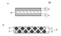
- FIG. 1 is a schematic cross-sectional view of an all-solid-state battery according to an embodiment
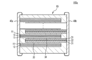
- FIG. 4 is a schematic cross-sectional view of another all-solid-state battery
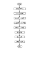
- It is a figure which illustrates the flow of the manufacturing method of an all-solid-state battery.
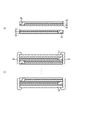
- It is a figure which illustrates a lamination process.
- FIG. 10 is a diagram illustrating the flow of another method for manufacturing an all-solid-state battery;
- FIG. 1(a) is a schematic cross-sectional view showing the basic structure of an all-solid-state battery 100.
- the all-solid battery 100 has a structure in which a solid electrolyte layer 30 is sandwiched between a first electrode 10 and a second electrode 20 .
- the first electrode 10 is formed on the first main surface of the solid electrolyte layer 30 and has a structure in which the first electrode layer 11 and the first current collector layer 12 are laminated.
- a first electrode layer 11 is provided.
- the second electrode 20 is formed on the second main surface of the solid electrolyte layer 30, has a structure in which a second electrode layer 21 and a second current collector layer 22 are laminated, and is provided on the solid electrolyte layer 30 side. A second electrode layer 21 is provided.
- one of the first electrode 10 and the second electrode 20 is used as a positive electrode, and the other is used as a negative electrode.
- the first electrode 10 is used as a positive electrode
- the second electrode 20 is used as a negative electrode.
- the solid electrolyte layer 30 is mainly composed of a solid electrolyte having ionic conductivity. As illustrated in FIG. 1B, the solid electrolyte of the solid electrolyte layer 30 has a structure in which a plurality of first solid electrolyte particles 31 and a plurality of second solid electrolyte particles 32 are mixed.
- the first solid electrolyte particles 31 are oxide crystals containing Li, Ta, and P, such as Li--Ta--P--O compounds.
- XRD X-ray diffraction
- the first solid electrolyte particles 31 are confirmed to have a monoclinic crystal structure.
- the first solid electrolyte particles 31 are LiTa 2 PO 8 based compounds.
- the second solid electrolyte particles 32 are a lithium-containing material and have a sintering initiation temperature lower than that of the first solid electrolyte particles 31 .
- the first solid electrolyte particles 31 have a Li-poor structure instead of having a Li:Ta:P molar ratio of 1:2:1. That is, in the first solid electrolyte particles 31, the ratio of the Li content to 1 mol of P is less than 1 mol. Since the first solid electrolyte particles 31 have the Li-poor structure, the monoclinic crystal structure is easily stabilized. Therefore, even if it is mixed with a lithium-containing material that can be sintered at a low temperature and fired, the reaction between the two components is suppressed, and a heterogeneous phase that can become a high-resistance component is less likely to be formed at the interface between the two, resulting in high ionic conductivity. As described above, the solid electrolyte layer 30 exhibits high ion conductivity and can be fired at a low temperature.
- the ratio of the Li content to 1 mol of P is 0.5 mol or more, preferably 0.6 or more, and more preferably 0.7 or more.
- the ratio of the Li content to 1 mol of P in the first solid electrolyte particles 31 is 0.95 or less, preferably 0.9 or less, and more preferably 0.8 or less.
- the Ta/P molar ratio is preferably 1.7 or more, more preferably 1.8 or more, and even more preferably 1.9 or more.
- the Ta/P molar ratio is preferably 2.3 or less, more preferably 2.2 or less, and even more preferably 2.1 or less.
- the average crystal grain size of the first solid electrolyte particles 31 is small, the densification of the solid electrolyte layer is hindered, and the filling rate of the first solid electrolyte cannot be increased. It may not be possible to fully demonstrate it. Therefore, it is preferable to set a lower limit for the average crystal grain size of the first solid electrolyte particles 31 .
- the average crystal grain size of the first solid electrolyte particles 31 is preferably 1 ⁇ m or more, more preferably 2 ⁇ m or more, and even more preferably 3 ⁇ m or more.
- the average crystal grain size of the first solid electrolyte particles 31 is preferably 20 ⁇ m or less, more preferably 10 ⁇ m or less, and even more preferably 7 ⁇ m or less.
- the average crystal grain size of the first solid electrolyte particles 31 is, for example, the horizontal or vertical Ferret diameter of 50 first solid electrolyte particles 31 specified by EDS mapping in the cross section of the solid electrolyte layer 30. It can be measured by measuring the length and calculating the average value.
- the ratio of the first solid electrolyte particles 31 in the solid electrolyte layer 30 is high, it may become difficult to bake the solid electrolyte layer 30 at a sufficiently low temperature. Therefore, it is preferable to set an upper limit for the ratio of the first solid electrolyte particles 31 in the solid electrolyte layer 30 .
- the area ratio of the first solid electrolyte particles 31 is preferably 70% or less, more preferably 60% or less, and even more preferably 50% or less.
- the ratio of the second solid electrolyte particles 32 in the solid electrolyte layer 30 is high, there is a risk that sufficiently high ion conduction cannot be obtained. Therefore, it is preferable to set an upper limit for the ratio of the second solid electrolyte particles 32 in the solid electrolyte layer 30 .
- the area ratio of the second solid electrolyte particles 32 is preferably 80% or less, more preferably 70% or less, and 60% or less. More preferred.
- the area ratio between the first solid electrolyte particles 31 and the second solid electrolyte particles 32 is preferably 20:80 to 70:30, more preferably 30:70 to 60:40. is more preferred, and 40:60 to 50:50 is even more preferred.
- the area ratio between the first solid electrolyte particles 31 and the second solid electrolyte particles 32 in the cross section of the solid electrolyte layer 30 can be measured, for example, by observing the cross section with an SEM and performing EDS elemental mapping analysis.
- the second solid electrolyte particles 32 are not particularly limited as long as they contain lithium and have a sintering start temperature lower than that of the first solid electrolyte particles 31 .
- the second solid electrolyte particles 32 are Li—Ge—P—O based compounds, Li—Zr—P—O based compounds, Li—P—O based compounds, Li—BO based compounds, Li—Si—
- One or a plurality of O-based compounds may be used, or these elements may be combined, and these may contain Al, Y, La, and the like.
- Li—Ge—Zr—P—O based compounds Li—Si—B—O based compounds, Li—Al—Ge—P—O based compounds, Li—La—Zr—P—O based compounds, Li—Al A —PO-based compound or the like may be used.
- Li--Al--Ge--P--O compounds are preferably used as the second solid electrolyte particles 32 from the viewpoint of ion conductivity.
- the thickness of the solid electrolyte layer 30 is, for example, in the range of 2 ⁇ m to 25 ⁇ m, in the range of 4 ⁇ m to 20 ⁇ m, and in the range of 6 ⁇ m to 15 ⁇ m.
- the positive electrode active material of the first electrode 10 is not particularly limited. 7 ) 4 etc. are mentioned.
- the negative electrode active material of the second electrode 20 prior art in secondary batteries can be referred to as appropriate. compounds such as
- a solid electrolyte having ionic conductivity, a conductive material (conductive aid) such as carbon or metal, and the like are further added.
- a conductive material such as carbon or metal, and the like.
- an electrode layer paste can be obtained by uniformly dispersing a binder and a plasticizer in water or an organic solvent.
- the metal of the conductive aid include Pd, Ni, Cu, Fe, and alloys containing these.
- the first current collector layer 12 and the second current collector layer 22 are mainly composed of a conductive material.
- a conductive material for example, metal, carbon, or the like can be used as the conductive material of the first current collector layer 12 and the second current collector layer 22 .
- FIG. 2 is a schematic cross-sectional view of a stacked all-solid-state battery 100a in which a plurality of battery units are stacked.
- the all-solid-state battery 100a includes a laminated chip 60 having a substantially rectangular parallelepiped shape.
- the first external electrode 40a and the second external electrode 40b are provided so as to be in contact with two side surfaces of the four surfaces other than the top surface and the bottom surface of the stacking direction end.
- the two side surfaces may be two adjacent side surfaces or two side surfaces facing each other.
- the first external electrode 40a and the second external electrode 40b are provided so as to be in contact with two side surfaces (hereinafter referred to as two end surfaces) facing each other.
- a plurality of first collector layers 12 and a plurality of second collector layers 22 are alternately laminated. Edges of the plurality of first current collector layers 12 are exposed on the first end face of the laminated chip 60 and are not exposed on the second end face. Edges of the plurality of second current collector layers 22 are exposed on the second end surface of the laminated chip 60 and are not exposed on the first end surface. Thereby, the first current collector layer 12 and the second current collector layer 22 are alternately connected to the first external electrode 40a and the second external electrode 40b.
- a first electrode layer 11 is laminated on the first collector layer 12 .
- a solid electrolyte layer 30 is laminated on the first electrode layer 11 .
- the solid electrolyte layer 30 extends from the first external electrode 40a to the second external electrode 40b.
- a second electrode layer 21 is laminated on the solid electrolyte layer 30 .
- a second collector layer 22 is laminated on the second electrode layer 21 .
- Another second electrode layer 21 is laminated on the second collector layer 22 .
- Another solid electrolyte layer 30 is laminated on the second electrode layer 21 .
- the solid electrolyte layer 30 extends from the first external electrode 40a to the second external electrode 40b.
- a first electrode layer 11 is laminated on the solid electrolyte layer 30 .
- the first current collector layer 12 and the two first electrode layers 11 sandwiching it are regarded as one electrode
- the second current collector layer 22 and the two second electrode layers 21 sandwiching it are regarded as one electrode.
- the laminated chip 60 can be said to have a structure in which a plurality of internal electrodes and a plurality of solid electrolyte layers are alternately laminated.
- the all-solid-state battery 100a does not have to have a collector layer.
- the first current collector layer 12 and the second current collector layer 22 may not be provided.
- only the first electrode layer 11 constitutes the first electrode 10
- only the second electrode layer 21 constitutes the second electrode 20 .
- FIG. 4 is a diagram illustrating the flow of the method for manufacturing the all-solid-state battery 100a.
- powder of the solid electrolyte that constitutes the solid electrolyte layer 30 is prepared.
- the raw material powder of the first solid electrolyte particles 31 is synthesized, for example, by a solid-phase synthesis method.
- Li 3 PO 4 , Ta 2 O 5 and NH 4 H 2 PO 4 are mixed in a molar ratio of 0.4:1.4:1 and heat-treated at about 900° C. in air.
- LiOH.H 2 O is added to the reactant so that Li is in excess and mixed, and the main heat treatment is performed at 950 ° C. to 1300 ° C. to obtain an XRD measurement.
- a Li--Ta--P--O-based compound is synthesized so that the results confirm that it has a crystal structure belonging to the monoclinic system.
- the ratio of Li content to 1 mol of P in the synthesized Li--Ta--P--O compound is set to 0.50 mol or more and 0.95 mol or less.
- the Li--Ta--P--O compound is pulverized to a desired particle size with a wet ball mill.
- a vitreous precursor which is a lithium-containing material and has a sintering initiation temperature lower than that of the first solid electrolyte particles 31 is obtained by a conventional melting and quenching method.
- a conventional melting and quenching method Li 2 CO 3 , Al 2 O 3 , GeO 2 and P 2 O 5 as raw materials are mixed to form a glass melt at 1400° C., and the glass is produced by casting, and the desired particles are obtained by a dry ball mill. Grind to diameter.
- Solid electrolyte green sheet manufacturing process Next, the obtained powder is uniformly dispersed in an aqueous solvent or an organic solvent together with a binder, a dispersant, a plasticizer, etc., and wet pulverized to obtain a solid electrolyte slurry having a desired average particle size.
- a bead mill, a wet jet mill, various kneaders, a high-pressure homogenizer, or the like can be used, and it is preferable to use a bead mill from the viewpoint of being able to simultaneously adjust the particle size distribution and disperse.
- a binder is added to the obtained solid electrolyte slurry to obtain a solid electrolyte paste.
- a solid electrolyte green sheet By applying the obtained solid electrolyte paste, a solid electrolyte green sheet can be produced.
- the coating method is not particularly limited, and a slot die method, a reverse coating method, a gravure coating method, a bar coating method, a doctor blade method, or the like can be used.
- the particle size distribution after wet pulverization can be measured, for example, using a laser diffraction measurement device using a laser diffraction scattering method.
- an internal electrode paste for producing the above-described first electrode layer 11 and second electrode layer 21 is produced.
- an internal electrode paste can be obtained by uniformly dispersing a conductive aid, an electrode active material, a solid electrolyte material, a binder, a plasticizer, and the like in water or an organic solvent.
- the solid electrolyte material the solid electrolyte paste described above may be used.
- Pd, Ni, Cu, Fe, alloys containing these, various carbon materials, and the like may further be used as conductive aids.
- each internal electrode paste may be prepared separately.
- a current collector paste for manufacturing the above-described first current collector layer 12 and second current collector layer 22 is prepared.
- a current collector paste can be obtained by uniformly dispersing Pd powder, carbon black, plate-like graphite carbon, a binder, a dispersant, a plasticizer, and the like in water or an organic solvent.
- an external electrode paste for producing the first external electrode 40a and the second external electrode 40b is prepared.
- an external electrode paste can be obtained by uniformly dispersing a conductive material, an electrode active material, a solid electrolyte, a binder, a plasticizer, and the like in water or an organic solvent.
- a laminate process As illustrated in FIG. 5A, on one surface of a solid electrolyte green sheet 51, an internal electrode paste 52, a current collector paste 53, and an internal electrode paste 52 are printed.
- a reverse pattern 54 is printed on a region of the solid electrolyte green sheet 51 where the internal electrode paste 52 and the current collector paste 53 are not printed. As the reverse pattern 54, the same one as the solid electrolyte green sheet 51 can be used.
- a laminate is obtained by stacking a plurality of solid electrolyte green sheets 51 alternately after printing, and crimping a cover sheet 55 in which a plurality of solid electrolyte green sheets are bonded together from above and below in the stacking direction.
- a substantially rectangular parallelepiped laminate is obtained so that pairs of the internal electrode paste 52 and the current collector paste 53 are alternately exposed on the two end surfaces of the laminate.
- an external electrode paste 56 is applied to each of the two end faces by a dipping method or the like and dried. Thereby, a molding for forming the all-solid-state battery 100a is obtained.
- the firing conditions include, without particular limitation, an oxidizing atmosphere or a non-oxidizing atmosphere and a maximum temperature of preferably 500°C to 900°C, more preferably 600°C to 800°C.
- a step of holding below the maximum temperature in an oxidizing atmosphere may be provided to sufficiently remove the binder until the maximum temperature is reached.
- reoxidation treatment may be performed.
- the step of applying the current collector paste 53 in the step of FIG. 5(a) may be omitted.
- FIG. 6 is a flowchart illustrating the manufacturing method in this case.
- the external electrode paste 56 is not applied in the stacking process, and the external electrode paste 56 is applied to the two end faces of the laminated chip 60 obtained in the firing process and baked. Thereby, the first external electrode 40a and the second external electrode 40b can be formed.
- Li-poor powder is used as the raw material powder synthesized for the first solid electrolyte particles 31 .
- the monoclinic crystal structure is easily stabilized. Therefore, even if it is mixed with a lithium-containing material that can be sintered at a low temperature and fired, the reaction between the two components is suppressed, and a heterogeneous phase that can become a high-resistance component is less likely to be formed at the interface between the two, resulting in high ionic conductivity.
- the solid electrolyte layer 30 exhibiting high ionic conductivity can be fired at a low temperature.
- a Li—Ta—P—O compound and a Li—Al—Ge—P—O glass precursor having a non-stoichiometric composition were ground and mixed in a weight ratio of 30:70. It was pelletized with a uniaxial press so as to have a thickness of 0.5 mm, and fired at a top temperature of 650°C.
- the ion conductivity of the sintered body was 6.0 ⁇ 10 ⁇ 5 S/cm.
- the cross section was observed by SEM, and EDS elemental mapping analysis was performed, the area ratio of the Li—Ta—P—O compound and the Li—Al—Ge—P—O compound was approximately It was 20:80. No reaction product was observed at the particle interface between these compounds.
- a Li—Ta—P—O compound and a Li—Al—Ge—P—O glass precursor having a non-stoichiometric composition were ground and mixed in a weight ratio of 30:70. It was pelletized with a uniaxial press so as to have a thickness of 0.5 mm, and fired at a top temperature of 650°C.
- the ion conductivity of the sintered body was 8.0 ⁇ 10 ⁇ 5 S/cm.
- the cross section was observed by SEM, and EDS elemental mapping analysis was performed, the area ratio of the Li—Ta—P—O compound and the Li—Al—Ge—P—O compound was approximately It was 20:80. No reaction product was observed at the particle interface between these compounds.
- Example 3 a crystalline Li--Ta--P--O compound was synthesized and pulverized in the same manner as in Example 1.
- a Li—Ta—P—O compound and a Li—Al—Ge—P—O glass precursor having a non-stoichiometric composition were ground and mixed in a weight ratio of 30:70. It was pelletized with a uniaxial press so as to have a thickness of 0.5 mm, and fired at a top temperature of 650°C.
- the ion conductivity of the sintered body was 2.0 ⁇ 10 ⁇ 5 S/cm.
- the cross section was observed by SEM, and EDS elemental mapping analysis was performed, the area ratio of LiTa 2 PO 8 and the Li—Al—Ge—P—O compound was approximately 20:80. rice field. No reaction product was observed at the particle interface between these compounds.
- a Li—Ta—P—O compound and a Li—Al—Ge—P—O glass precursor having a non-stoichiometric composition were ground and mixed in a weight ratio of 30:70. It was pelletized with a uniaxial press so as to have a thickness of 0.5 mm, and fired at a top temperature of 650°C.
- the ion conductivity of the sintered body was 8.5 ⁇ 10 ⁇ 5 S/cm.
- the cross section was observed by SEM, and EDS elemental mapping analysis was performed, the area ratio of LiTa 2 PO 8 and the Li—Al—Ge—P—O compound was approximately 20:80. rice field. No reaction product was observed at the particle interface between these compounds.
- Example 5 a crystalline Li--Ta--P--O compound was synthesized and pulverized in the same manner as in Example 4.
- a Li—Ta—P—O compound and a Li—Al—Ge—P—O glass precursor having a non-stoichiometric composition were ground and mixed in a weight ratio of 30:70. It was pelletized with a uniaxial press so as to have a thickness of 0.5 mm, and fired at a top temperature of 650°C.
- the ion conductivity of the sintered body was 5.3 ⁇ 10 ⁇ 5 S/cm.
- the cross section was observed by SEM, and EDS elemental mapping analysis was performed, the area ratio of LiTa 2 PO 8 and the Li—Al—Ge—P—O compound was approximately 20:80. rice field. No reaction product was observed at the particle interface between these compounds.
- a Li—Ta—P—O compound and a Li—Al—Ge—P—O glass precursor having a non-stoichiometric composition were ground and mixed in a weight ratio of 30:70. It was pelletized with a uniaxial press so as to have a thickness of 0.5 mm, and fired at a top temperature of 650°C.
- the ion conductivity of the sintered body was 9.1 ⁇ 10 ⁇ 5 S/cm.
- the cross section was observed by SEM, and EDS elemental mapping analysis was performed, the area ratio of LiTa 2 PO 8 and the Li—Al—Ge—P—O compound was approximately 20:80. rice field. No reaction product was observed at the particle interface between these compounds.
- Example 7 a crystalline Li--Ta--P--O compound was synthesized and pulverized in the same manner as in Example 1.
- Li--Ta--P--O compound and the non-stoichiometric Li--Al--Ge--P--O-based glassy precursor material are ground and mixed in a weight ratio of 30:70, 2 wt % of Li 3 PO 4 was added to the Li—Al—Ge—P—O based glassy precursor (LAGP-g).
- LAGP-g Li—Al—Ge—P—O based glassy precursor
- the ion conductivity of the sintered body was 9.2 ⁇ 10 ⁇ 5 S/cm.
- the cross section was observed by SEM, and EDS elemental mapping analysis was performed, the area ratio of LiTa 2 PO 8 and the Li—Al—Ge—P—O compound was approximately 20:80. rice field. No reaction product was observed at the particle interface between these compounds.
- a Li—Ta—P—O compound and a Li—Al—Ge—P—O glass precursor having a non-stoichiometric composition were ground and mixed in a weight ratio of 30:70. It was pelletized with a uniaxial press so as to have a thickness of 0.5 mm, and fired at a top temperature of 650°C.
- the ionic conductivity of the sintered body was 5.0 ⁇ 10 ⁇ 6 S/cm.
- the cross section was observed by SEM, and EDS elemental mapping analysis was performed, the area ratio of LiTa 2 PO 8 and the Li—Al—Ge—P—O compound was approximately 20:80. rice field. A reaction product was formed at the particle interface between these compounds.
- a Li—Ta—P—O compound and a Li—Al—Ge—P—O glass precursor having a non-stoichiometric composition were ground and mixed in a weight ratio of 30:70. It was pelletized with a uniaxial press so as to have a thickness of 0.5 mm, and fired at a top temperature of 650°C.
- the ionic conductivity of the sintered body was 8.0 ⁇ 10 ⁇ 6 S/cm.
- the cross section was observed by SEM, and EDS elemental mapping analysis was performed, the area ratio of LiTa 2 PO 8 and the Li—Al—Ge—P—O compound was approximately 20:80. rice field. A reaction product was formed at the particle interface between these compounds.
- Table 1 shows the results of Examples 1 to 7 and Comparative Examples 1 and 2.
Landscapes
- Engineering & Computer Science (AREA)
- Chemical & Material Sciences (AREA)
- Manufacturing & Machinery (AREA)
- Chemical Kinetics & Catalysis (AREA)
- Electrochemistry (AREA)
- General Chemical & Material Sciences (AREA)
- Ceramic Engineering (AREA)
- General Physics & Mathematics (AREA)
- Condensed Matter Physics & Semiconductors (AREA)
- Inorganic Chemistry (AREA)
- Physics & Mathematics (AREA)
- Materials Engineering (AREA)
- Structural Engineering (AREA)
- Organic Chemistry (AREA)
- Secondary Cells (AREA)
- Conductive Materials (AREA)
Abstract
固体電解質は、LiとTaとPを含む酸化物型の固体電解質であって、1molのPに対するLi含有量の比率が0.5mol以上0.95mol以下であり、XRD測定の結果で、単斜晶に帰属する結晶構造を有することが確認されることを特徴とする。
Description
本発明は、固体電解質、全固体電池、固体電解質の製造方法、および全固体電池の製造方法に関する。
近年、二次電池の需要が急速に拡大しており、電解質に有機電解液を使用したリチウムイオン二次電池が実用化されている。しかしながら、電解液の液漏れなどの点から、より安全性の高い固体電解質への期待が高まり、固体電解質を用いた全固体電池の開発が盛んに進められている(例えば、特許文献1参照)。
安全性を考慮すると、大気に暴露されても有毒なガスを発生する硫化物系固体電解質よりも、大気中で安定な酸化物系固体電解質を用いることが望ましい。一方、酸化物系固体電解質は、イオン伝導発現や電極活物質との良好な界面形成のために、高温での焼結が求められている。高温焼結では、固体電解質と電極活物質との間の相互拡散反応が課題となる。
酸化物系固体電解質としては、ガーネット型構造を有するLi-La-Zr-O系化合物やその元素置換体、NASICON型結晶構造のLi-Al-Ti-P-O系やLi-Al-Ge-P-O系の化合物、ペロブスカイト型結晶構造を有するLi-La-Ti-O系の化合物などが知られている。近年、Li-Ta-P-O系化合物も報告されているが、いずれも比較的高い温度での熱処理(焼成)が求められ、電極活物質との界面形成時の相互拡散反応が懸念される。
このような課題から、酸化物系固体電解質の焼結温度を低温化させるためにガラス材料と混合させる手法が検討されている。例えば、特許文献1では、酸化物結晶を第一のリチウムイオン伝導体とし、600℃以下での焼結が可能なガラス材料である第二のリチウムイオン伝導体と混合することで、600℃以下の焼結温度において高いリチウムイオン伝導性を得ている。
特許文献1によると、第一のリチウムイオン伝導体と第二のリチウムイオン伝導体を用いて600℃以下で熱処理することで、高いリチウムイオン伝導性を有する固体電解質を得られることが提案されている。しかしながら、600℃以下と比較的低い温度での熱処理であり、電解質層および固体電解質層をさらに緻密化させたり、両層の界面抵抗を低減させたりしたい場合、より高温での熱処理が必要となるため、両者の成分拡散による反応が懸念事項として挙げられる。600℃以上の熱処理では、とりわけリチウムの相互拡散反応が起きやすく、高結晶高イオン伝導の固体電解質の結晶構造変化、イオン伝導低下が懸念される。
本発明は、上記課題に鑑みなされたものであり、高いイオン伝導を発現するとともに低温焼成可能な固体電解質、全固体電池、固体電解質の製造方法および全固体電池の製造方法を提供することを目的とする。
本発明に係る固体電解質は、LiとTaとPを含む酸化物型の固体電解質であって、1molのPに対するLi含有量の比率が0.5mol以上0.95mol以下であり、XRD測定の結果で、単斜晶に帰属する結晶構造を有することが確認されることを特徴とする。
上記固体電解質において、Ta/Pのモル比が1.7以上2.3以下であってもよい。
本発明に係る全固体電池は、本発明に係る上記いずれかの固体電解質を第1固体電解質として含み、前記第1固体電解質よりも焼結開始温度が低いリチウム含有材料を第2固体電解質として含む固体電解質層と、電極活物質を含み、前記固体電解質層の第1主面上に形成された第1電極と、電極活物質を含み、前記固体電解質層の前記第1主面に対向する第2主面上に形成された第2電極と、を備えることを特徴とする。
上記全固体電池において、前記固体電解質層、前記第1電極および前記第2電極を一つの単位として、前記単位が複数積み重ねられていてもよい。
上記全固体電池において、前記第1電極および前記第2電極のうち、一方は正極活物質を含み、他方は負極活物質を含んでいてもよい。
上記全固体電池において、前記固体電解質層における前記第1固体電解質の平均結晶粒径は、1μm以上20μm以下であってもよい。
上記全固体電池において、前記リチウム含有材料は、Li-Ge-P-O系化合物、Li-Zr-P-O系化合物、Li-P-O系化合物、Li-B-O系化合物、Li-Si-O系化合物、Li-Ge-Zr-P-O系化合物、Li-Si-B-O系化合物、Li-Al-Ge-P-O系化合物、Li-La-Zr-P-O系化合物、Li-Al-P-O系化合物の少なくとも1つであってもよい。
本発明に係る固体電解質の製造方法は、LiとTaとPを含み、1molのPに対するLi含有量が0.5mol以上0.95mol以下である原料から、950℃以上1300℃以下の温度で、XRD測定の結果で単斜晶に帰属する結晶構造を有することが確認される酸化物型の固体電解質を合成することを特徴とする。
本発明に係る全固体電池の製造方法は、LiとTaとPを含み、1molのPに対するLi含有量が0.5mol以上0.95mol以下であり、XRD測定の結果で、単斜晶に帰属する結晶構造を有することが確認される酸化物型の固体電解質の粉末を第1固体電解質粉末として含み、前記第1固体電解質粉末よりも焼結開始温度が低いリチウム含有材料の粉末を第2固体電解質粉末として含むグリーンシートと、前記グリーンシートの第1主面上に形成された第1電極層用ペースト塗布物と、前記グリーンシートの第2主面上に形成された第2電極層用ペースト塗布物と、を有する積層体を用意する工程と、前記積層体を焼成する焼成工程と、を含むことを特徴とする。
上記全固体電池の製造方法において、前記焼成工程における焼成温度を、500℃以上900℃以下にしてもよい。
本発明によれば、高いイオン伝導を発現するとともに低温焼成可能な固体電解質、全固体電池、固体電解質の製造方法、および全固体電池の製造方法を提供することができる。
以下、図面を参照しつつ、実施形態について説明する。
(実施形態)
図1(a)は、全固体電池100の基本構造を示す模式的断面図である。図1(a)で例示するように、全固体電池100は、第1電極10と第2電極20とによって、固体電解質層30が挟持された構造を有する。第1電極10は、固体電解質層30の第1主面上に形成されており、第1電極層11および第1集電体層12が積層された構造を有し、固体電解質層30側に第1電極層11を備える。第2電極20は、固体電解質層30の第2主面上に形成されており、第2電極層21および第2集電体層22が積層された構造を有し、固体電解質層30側に第2電極層21を備える。
図1(a)は、全固体電池100の基本構造を示す模式的断面図である。図1(a)で例示するように、全固体電池100は、第1電極10と第2電極20とによって、固体電解質層30が挟持された構造を有する。第1電極10は、固体電解質層30の第1主面上に形成されており、第1電極層11および第1集電体層12が積層された構造を有し、固体電解質層30側に第1電極層11を備える。第2電極20は、固体電解質層30の第2主面上に形成されており、第2電極層21および第2集電体層22が積層された構造を有し、固体電解質層30側に第2電極層21を備える。
全固体電池100を二次電池として用いる場合には、第1電極10および第2電極20の一方を正極として用い、他方を負極として用いる。本実施形態においては、一例として、第1電極10を正極として用い、第2電極20を負極として用いるものとする。
固体電解質層30は、イオン伝導性を有する固体電解質を主成分とする。図1(b)で例示するように、固体電解質層30の固体電解質は、複数の第1固体電解質粒子31と、複数の第2固体電解質粒子32とが混在する構造を有している。第1固体電解質粒子31は、LiとTaとPとを含む酸化物系結晶であって、例えばLi-Ta-P-O系化合物である。第1固体電解質粒子31は、XRD(X線回折)測定の結果として、単斜晶の結晶構造に帰属することが確認される。例えば、第1固体電解質粒子31は、LiTa2PO8系化合物である。第2固体電解質粒子32は、リチウム含有材料であって、第1固体電解質粒子31よりも低い焼結開始温度を有している。
なお、「XRD測定で単斜晶の結晶構造に帰属することが確認される」とは、Cu Kαを線源とするXRD測定で少なくとも25.2°~25.7°にメインピークが観測され、さらに20.2°~20.7°と24.6°~25.1°と34.6°~35.1°の三範囲にメインピーク強度の30%~70%の回折ピーク強度のサブピークが観測されるというような結果が得られることを意味している。
第1固体電解質粒子31は、Li:Ta:Pのモル比を1:2:1とするのではなく、Liプアの構造を有している。すなわち、第1固体電解質粒子31において、1molのPに対して、Li含有量の比率が1mol未満となっている。第1固体電解質粒子31がLiプアの構造を有していることで、単斜晶の結晶構造が安定化しやすくなる。したがって、低温焼結可能なリチウム含有材料と混合して焼成しても両者の成分の反応が抑制され、高抵抗成分となり得る異相が両者の界面に形成されにくく、高いイオン伝導性が得られる。以上のことから、固体電解質層30は、高いイオン伝導を発現するとともに低温焼成可能である。
なお、第1固体電解質粒子31において、1molのPに対して、Li含有量の比率が小さすぎると、イオン伝導性低下のおそれがある。そこで、1molのPに対するLi含有量の比率に下限を設ける。本実施形態においては、1molのPに対して、Li含有量の比率は、0.5mol以上であり、0.6以上であることが好ましく、0.7以上であることがより好ましい。
一方、第1固体電解質粒子31において、1molのPに対して、Li含有量の比率が大きすぎると、単斜晶の結晶構造が十分に安定化しないおそれがある。そこで、そこで、1molのPに対するLi含有量の比率に上限を設ける。本実施形態においては、1molのPに対して、Li含有量の比率は、0.95以下であり、0.9以下であることが好ましく、0.8以下であることがより好ましい。
第1固体電解質粒子31において、Ta/Pのモル比が小さいと、二次相生成のおそれがある。そこで、第1固体電解質粒子31において、Ta/Pのモル比に下限を設けることが好ましい。例えば、Ta/Pのモル比は、1.7以上であることが好ましく、1.8以上であることがより好ましく、1.9以上であることがさらに好ましい。
第1固体電解質粒子31において、Ta/Pのモル比が大きいと、二次相生成とイオン伝導性低下のおそれがある。そこで、第1固体電解質粒子31において、Ta/Pのモル比に上限を設けることが好ましい。例えば、Ta/Pのモル比は、2.3以下であることが好ましく、2.2以下であることがより好ましく、2.1以下であることがさらに好ましい。
固体電解質層30において、第1固体電解質粒子31の平均結晶粒径が小さいと、固体電解質層の緻密化が阻害され、第1固体電解質の充填率を高くすることができないため、イオン伝導性を十分に発揮できないおそれがある。そこで、第1固体電解質粒子31の平均結晶粒径に下限を設けることが好ましい。例えば、第1固体電解質粒子31の平均結晶粒径は、1μm以上であることが好ましく、2μm以上であることがより好ましく、3μm以上であることがさらに好ましい。
固体電解質層30において、第1固体電解質粒子31の平均結晶粒径が大きいと、固体電解質層30の層厚を薄くすることができないため、十分なエネルギー密度や応答性を確保することが難しくなるおそれがある。そこで、第1固体電解質粒子31の平均結晶粒径に上限を設けることが好ましい。例えば、第1固体電解質粒子31の平均結晶粒径は、20μm以下であることが好ましく、10μm以下であることがより好ましく、7μm以下であることがさらに好ましい。
第1固体電解質粒子31の平均結晶粒径は、例えば、固体電解質層30の断面におけるEDSマッピングで特定される第1固体電解質粒子31の50個について、水平あるいは垂直フェレ―径(Ferret Diameter)を測長し、平均値を出すというように測定することができる。
固体電解質層30における第1固体電解質粒子31の比率が高いと、十分に低い温度での固体電解質層30の焼成が困難となるおそれがある。そこで、固体電解質層30における第1固体電解質粒子31の比率に上限を設けることが好ましい。例えば、固体電解質層30の断面において、第1固体電解質粒子31の面積比率は、70%以下であることが好ましく、60%以下であることがより好ましく、50%以下であることがさらに好ましい。
一方、固体電解質層30における第2固体電解質粒子32の比率が高いと、十分高いイオン伝導が得られないおそれがある。そこで、固体電解質層30における第2固体電解質粒子32の比率に上限を設けることが好ましい。本実施形態においては、固体電解質層30の断面において、第2固体電解質粒子32の面積比率は80%以下であることが好ましく、70%以下であることがより好ましく、60%以下であることがさらに好ましい。
固体電解質層30の断面において、第1固体電解質粒子31と第2固体電解質粒子32との面積比は、20:80~70:30であることが好ましく、30:70~60:40であることがより好ましく、40:60~50:50であることがさらに好ましい。
固体電解質層30の断面における第1固体電解質粒子31と第2固体電解質粒子32との面積比は、例えば、断面についてSEM観察を行い、EDS元素マッピング分析を行うことによって測定することができる。
第2固体電解質粒子32は、リチウムを含み、第1固体電解質粒子31よりも焼結開始温度の低い材料であれば特に限定されるものではない。例えば、第2固体電解質粒子32は、Li-Ge-P-O系化合物、Li-Zr-P-O系化合物、Li-P-O系化合物、Li-B-O系化合物、Li-Si-O系化合物などのうちの1つあるいは複数使用してもよく、また、これらの元素を組み合わせてもよく、さらに、これらにAl、Y、Laなどを含んでもよい。例えばLi-Ge-Zr-P-O系化合物、Li-Si-B-O系化合物、Li-Al-Ge-P-O系化合物、Li-La-Zr-P-O系化合物、Li-Al-P-O系化合物などとしてもよい。これらの中で、イオン伝導性の観点から、Li-Al-Ge-P-O系化合物を第2固体電解質粒子32として用いることが好ましい。
なお、固体電解質層30の厚みは、例えば、2μm~25μmの範囲であり、4μm~20μmの範囲であり、6μm~15μmの範囲である。
第1電極10の正極活物質は、特に限定されないが、第2固体電解質粒子32にリン酸塩系化合物を用いる場合は、LiCoPO4やLi2CoP2O7やLi6Co5(P2O7)4等が挙げられる。第2電極20の負極活物質については、二次電池における従来技術を適宜参照することができ、例えば、チタン酸化物、リチウムチタン複合酸化物、リチウムチタン複合リン酸塩、カーボン、リン酸バナジウムリチウムなどの化合物が挙げられる。
第1電極層11および第2電極層21の作製においては、これら電極活物質に加えて、イオン伝導性を有する固体電解質や、カーボンや金属といった導電性材料(導電助剤)などをさらに添加してもよい。これらの部材については、バインダと可塑剤を水あるいは有機溶剤に均一分散させることで電極層用ペーストを得ることができる。導電助剤の金属としては、Pd、Ni、Cu、Fe、これらを含む合金などが挙げられる。
第1集電体層12および第2集電体層22は、導電性材料を主成分とする。例えば、第1集電体層12および第2集電体層22の導電性材料として、金属、カーボンなどを用いることができる。
図2は、複数の電池単位が積層された積層型の全固体電池100aの模式的断面図である。全固体電池100aは、略直方体形状を有する積層チップ60を備える。積層チップ60において、積層方向端の上面および下面以外の4面のうちの2面である2側面に接するように、第1外部電極40aおよび第2外部電極40bが設けられている。当該2側面は、隣接する2側面であってもよく、互いに対向する2側面であってもよい。本実施形態においては、互いに対向する2側面(以下、2端面と称する)に接するように第1外部電極40aおよび第2外部電極40bが設けられているものとする。
以下の説明において、全固体電池100と同一の組成範囲、同一の厚み範囲、および同一の粒度分布範囲を有するものについては、同一符号を付すことで詳細な説明を省略する。
全固体電池100aにおいては、複数の第1集電体層12と複数の第2集電体層22とが、交互に積層されている。複数の第1集電体層12の端縁は、積層チップ60の第1端面に露出し、第2端面には露出していない。複数の第2集電体層22の端縁は、積層チップ60の第2端面に露出し、第1端面には露出していない。それにより、第1集電体層12および第2集電体層22は、第1外部電極40aと第2外部電極40bとに、交互に導通している。
第1集電体層12上には、第1電極層11が積層されている。第1電極層11上には、固体電解質層30が積層されている。固体電解質層30は、第1外部電極40aから第2外部電極40bにかけて延在している。固体電解質層30上には、第2電極層21が積層されている。第2電極層21上には、第2集電体層22が積層されている。第2集電体層22上には、別の第2電極層21が積層されている。当該第2電極層21上には、別の固体電解質層30が積層されている。当該固体電解質層30は、第1外部電極40aから第2外部電極40bにかけて延在している。当該固体電解質層30上には、第1電極層11が積層されている。全固体電池100aにおいては、これらの積層単位が繰り返されている。それにより、全固体電池100aは、複数の電池単位が積層された構造を有している。
なお、第1集電体層12と、それを挟む2層の第1電極層11を1つの電極と捉え、第2集電体層22と、それを挟む2層の第2電極層21を1つの電極と捉えると、積層チップ60は、複数の内部電極と複数の固体電解質層とが、交互に積層された構造を有していると言える。
全固体電池100aは、集電体層を備えていなくてもよい。例えば、図3で例示するように、第1集電体層12および第2集電体層22は設けられていなくてもよい。この場合、第1電極層11だけで第1電極10が構成され、第2電極層21だけで第2電極20が構成される。
続いて、図2で例示した全固体電池100aの製造方法について説明する。図4は、全固体電池100aの製造方法のフローを例示する図である。
(セラミック原料粉末作製工程)
まず、上述の固体電解質層30を構成する固体電解質の粉末を作製する。第1固体電解質粒子31の原料粉末は、例えば、固相合成法にて合成する。例えば、Li3PO4とTa2O5とNH4H2PO4とを0.4:1.4:1のモル比で混合し、大気中900℃程度で熱処理する。得られた反応物を擂潰混合後、反応物に対してLiOH・H2OをLiが過剰になるように添加して混合し、950℃~1300℃で本熱処理することにより、XRD測定の結果で、単斜晶に帰属する結晶構造を有することが確認されるようにLi-Ta-P-O系化合物を合成する。合成されるLi-Ta-P-O系化合物において1molのPに対するLi含有量の比率を、0.50mol以上0.95mol以下とする。Li-Ta-P-O系化合物は、湿式ボールミルで所望の粒子径まで粉砕処理する。
まず、上述の固体電解質層30を構成する固体電解質の粉末を作製する。第1固体電解質粒子31の原料粉末は、例えば、固相合成法にて合成する。例えば、Li3PO4とTa2O5とNH4H2PO4とを0.4:1.4:1のモル比で混合し、大気中900℃程度で熱処理する。得られた反応物を擂潰混合後、反応物に対してLiOH・H2OをLiが過剰になるように添加して混合し、950℃~1300℃で本熱処理することにより、XRD測定の結果で、単斜晶に帰属する結晶構造を有することが確認されるようにLi-Ta-P-O系化合物を合成する。合成されるLi-Ta-P-O系化合物において1molのPに対するLi含有量の比率を、0.50mol以上0.95mol以下とする。Li-Ta-P-O系化合物は、湿式ボールミルで所望の粒子径まで粉砕処理する。
第2固体電解質粒子32の原料粉末として、リチウム含有材料であって第1固体電解質粒子31よりも低い焼結開始温度を有しているガラス状前駆物質を、従来公知の溶融急冷法により得る。例えば、原料のLi2CO3、Al2O3、GeO2、P2O5を混合し、1400℃でガラス融液とした後、キャストすることでガラスを作製し、乾式ボールミルで所望の粒子径まで粉砕処理する。
(固体電解質グリーンシート作製工程)
次に、得られた粉末を、結着材、分散剤、可塑剤などとともに、水性溶媒あるいは有機溶媒に均一に分散させて、湿式粉砕を行うことで、所望の平均粒径を有する固体電解質スラリを得る。このとき、ビーズミル、湿式ジェットミル、各種混錬機、高圧ホモジナイザーなどを用いることができ、粒度分布の調整と分散とを同時に行うことができる観点からビーズミルを用いることが好ましい。得られた固体電解質スラリにバインダを添加して固体電解質ペーストを得る。得られた固体電解質ペーストを塗工することで、固体電解質グリーンシートを作製することができる。塗工方法は、特に限定されるものではなく、スロットダイ方式、リバースコート方式、グラビアコート方式、バーコート方式、ドクターブレード方式などを用いることができる。湿式粉砕後の粒度分布は、例えば、レーザ回折散乱法を用いたレーザ回折測定装置を用いて測定することができる。
次に、得られた粉末を、結着材、分散剤、可塑剤などとともに、水性溶媒あるいは有機溶媒に均一に分散させて、湿式粉砕を行うことで、所望の平均粒径を有する固体電解質スラリを得る。このとき、ビーズミル、湿式ジェットミル、各種混錬機、高圧ホモジナイザーなどを用いることができ、粒度分布の調整と分散とを同時に行うことができる観点からビーズミルを用いることが好ましい。得られた固体電解質スラリにバインダを添加して固体電解質ペーストを得る。得られた固体電解質ペーストを塗工することで、固体電解質グリーンシートを作製することができる。塗工方法は、特に限定されるものではなく、スロットダイ方式、リバースコート方式、グラビアコート方式、バーコート方式、ドクターブレード方式などを用いることができる。湿式粉砕後の粒度分布は、例えば、レーザ回折散乱法を用いたレーザ回折測定装置を用いて測定することができる。
(内部電極用ペースト作製工程)
次に、上述の第1電極層11および第2電極層21の作製用の内部電極用ペーストを作製する。例えば、導電助剤、電極活物質、固体電解質材料、バインダ、可塑剤などを水あるいは有機溶剤に均一分散させることで内部電極用ペーストを得ることができる。固体電解質材料として、上述した固体電解質ペーストを用いてもよい。導電助剤として、Pd、Ni、Cu、Fe、これらを含む合金や各種カーボン材料などをさらに用いてもよい。第1電極層11と第2電極層21とで組成が異なる場合には、それぞれの内部電極用ペーストを個別に作製すればよい。
次に、上述の第1電極層11および第2電極層21の作製用の内部電極用ペーストを作製する。例えば、導電助剤、電極活物質、固体電解質材料、バインダ、可塑剤などを水あるいは有機溶剤に均一分散させることで内部電極用ペーストを得ることができる。固体電解質材料として、上述した固体電解質ペーストを用いてもよい。導電助剤として、Pd、Ni、Cu、Fe、これらを含む合金や各種カーボン材料などをさらに用いてもよい。第1電極層11と第2電極層21とで組成が異なる場合には、それぞれの内部電極用ペーストを個別に作製すればよい。
(集電体用ペースト作製工程)
次に、上述の第1集電体層12および第2集電体層22の作製用の集電体用ペーストを作製する。例えば、Pdの粉末、カーボンブラック、板状グラファイトカーボン、バインダ、分散剤、可塑剤などを水あるいは有機溶剤に均一分散させることで、集電体用ペーストを得ることができる。
次に、上述の第1集電体層12および第2集電体層22の作製用の集電体用ペーストを作製する。例えば、Pdの粉末、カーボンブラック、板状グラファイトカーボン、バインダ、分散剤、可塑剤などを水あるいは有機溶剤に均一分散させることで、集電体用ペーストを得ることができる。
(外部電極用ペースト作製工程)
次に、上述の第1外部電極40aおよび第2外部電極40bの作製用の外部電極用ペーストを作製する。例えば、導電性材料、電極活物質、固体電解質、バインダ、可塑剤などを水あるいは有機溶剤に均一分散させることで外部電極用ペーストを得ることができる。
次に、上述の第1外部電極40aおよび第2外部電極40bの作製用の外部電極用ペーストを作製する。例えば、導電性材料、電極活物質、固体電解質、バインダ、可塑剤などを水あるいは有機溶剤に均一分散させることで外部電極用ペーストを得ることができる。
(積層工程)
図5(a)で例示するように、固体電解質グリーンシート51の一面に、内部電極用ペースト52を印刷し、さらに集電体用ペースト53を印刷し、さらに内部電極用ペースト52を印刷する。固体電解質グリーンシート51上で内部電極用ペースト52および集電体用ペースト53が印刷されていない領域には、逆パターン54を印刷する。逆パターン54として、固体電解質グリーンシート51と同様のものを用いることができる。印刷後の複数の固体電解質グリーンシート51を、交互にずらして積層し、積層方向の上下から、複数枚の固体電解質グリーンシートを貼り合わせたカバーシート55を圧着することで、積層体を得る。この場合、当該積層体において、2端面に交互に、内部電極用ペースト52および集電体用ペースト53のペアが露出するように、略直方体形状の積層体を得る。次に、図5(b)で例示するように、2端面のそれぞれに、ディップ法等で外部電極用ペースト56を塗布して乾燥させる。これにより、全固体電池100aを形成するための成型体が得られる。
図5(a)で例示するように、固体電解質グリーンシート51の一面に、内部電極用ペースト52を印刷し、さらに集電体用ペースト53を印刷し、さらに内部電極用ペースト52を印刷する。固体電解質グリーンシート51上で内部電極用ペースト52および集電体用ペースト53が印刷されていない領域には、逆パターン54を印刷する。逆パターン54として、固体電解質グリーンシート51と同様のものを用いることができる。印刷後の複数の固体電解質グリーンシート51を、交互にずらして積層し、積層方向の上下から、複数枚の固体電解質グリーンシートを貼り合わせたカバーシート55を圧着することで、積層体を得る。この場合、当該積層体において、2端面に交互に、内部電極用ペースト52および集電体用ペースト53のペアが露出するように、略直方体形状の積層体を得る。次に、図5(b)で例示するように、2端面のそれぞれに、ディップ法等で外部電極用ペースト56を塗布して乾燥させる。これにより、全固体電池100aを形成するための成型体が得られる。
(焼成工程)
次に、得られた積層体を焼成する。焼成の条件は酸化性雰囲気下あるいは非酸化性雰囲気下で、最高温度を好ましくは500℃~900℃、より好ましくは600℃~800℃などとすることが特に限定なく挙げられる。最高温度に達するまでにバインダを十分に除去するために酸化性雰囲気において最高温度より低い温度で保持する工程を設けてもよい。プロセスコストを低減するためにはできるだけ低温で焼成することが望ましい。焼成後に、再酸化処理を施してもよい。以上の工程により、全固体電池100aが生成される。
次に、得られた積層体を焼成する。焼成の条件は酸化性雰囲気下あるいは非酸化性雰囲気下で、最高温度を好ましくは500℃~900℃、より好ましくは600℃~800℃などとすることが特に限定なく挙げられる。最高温度に達するまでにバインダを十分に除去するために酸化性雰囲気において最高温度より低い温度で保持する工程を設けてもよい。プロセスコストを低減するためにはできるだけ低温で焼成することが望ましい。焼成後に、再酸化処理を施してもよい。以上の工程により、全固体電池100aが生成される。
図2で例示した全固体電池100aについては、図5(a)の工程において集電体用ペースト53を塗布する工程を省略すればよい。
なお、第1外部電極40aおよび第2外部電極40bは、焼成工程後に焼き付けてもよい。図6は、この場合の製造方法を例示するフロー図である。例えば、積層工程で外部電極用ペースト56を塗布せず、焼成工程で得られた積層チップ60の2端面に外部電極用ペースト56を塗布し、焼き付ける。それにより、第1外部電極40aおよび第2外部電極40bを形成することができる。
本実施形態によれば、第1固体電解質粒子31用に合成された原料粉末に、Liプアのものを用いる。この場合、単斜晶の結晶構造が安定化しやすくなる。したがって、低温焼結可能なリチウム含有材料と混合して焼成しても両者の成分の反応が抑制され、高抵抗成分となり得る異相が両者の界面に形成されにくく、高いイオン伝導性が得られる。以上のことから、高いイオン電導を発現する固体電解質層30を低温焼成することができる。
以下、実施形態に従って全固体電池を作製し、特性について調べた。
(実施例1)
実施例1では、結晶性のLi-Ta-P-O系化合物を固相合成法にて合成した。具体的には、Li3PO4とTa2O5とNH4H2PO4とを0.4:1.4:1のモル比で混合し、大気中900℃で熱処理した。得られた反応物を擂潰混合後、反応物に対してLiOH・H2OをLiが10mol%過剰になるように添加して混合し、1100℃で本熱処理することにより合成した。合成粉は、XRD測定の結果、単斜晶の単相であることを確認した。また、合成粉をICP分析したところ、1molのPに対するLi含有量の比率は0.88molであった。合成粉は、湿式ボールミルでD50=4μmまで粉砕処理した。
実施例1では、結晶性のLi-Ta-P-O系化合物を固相合成法にて合成した。具体的には、Li3PO4とTa2O5とNH4H2PO4とを0.4:1.4:1のモル比で混合し、大気中900℃で熱処理した。得られた反応物を擂潰混合後、反応物に対してLiOH・H2OをLiが10mol%過剰になるように添加して混合し、1100℃で本熱処理することにより合成した。合成粉は、XRD測定の結果、単斜晶の単相であることを確認した。また、合成粉をICP分析したところ、1molのPに対するLi含有量の比率は0.88molであった。合成粉は、湿式ボールミルでD50=4μmまで粉砕処理した。
次に、非化学量論組成のLi-Al-Ge-P-O系ガラス状前駆物質を、従来公知の溶融急冷法により得た。具体的には、原料のLi2CO3、Al2O3、GeO2、P2O5を混合し、1400℃でガラス融液とした後、キャストすることでガラスを作製し、乾式ボールミルでD50=2μmまで粉砕処理した。このとき、ガラス状物質でのPに対するLiのモル比は、0.63であった。
Li-Ta-P-O系化合物と非化学量論組成のLi-Al-Ge-P-O系ガラス状前駆物質とを、重量比で30:70となるように擂潰混合し、Φ15mm、厚み0.5mmとなるように一軸プレス機でペレット化し、トップ温度650℃で焼成した。
焼結体のイオン伝導は、6.0×10⁻⁵S/cmであった。焼結体を破断し、断面のSEM観察を行い、EDS元素マッピング分析を行ったところ、Li-Ta-P-O系化合物とLi-Al-Ge-P-O系化合物の面積比率は、凡そ20:80であった。これらの化合物同士の粒子界面には、反応生成物は認められなかった。
(実施例2)
実施例2では、結晶性のLi-Ta-P-O系化合物を固相合成法にて合成した。具体的には、Li3PO4とTa2O5とNH4H2PO4とを0.35:1.35:1のモル比で混合し、大気中900℃で熱処理した。得られた反応物を擂潰混合後、反応物に対してLiOH・H2OをLiが15mol%過剰になるように添加して混合し、1300℃で本熱処理することにより合成した。合成粉は、XRD測定の結果、単斜晶の単相であることを確認した。また、合成粉をICP分析したところ、1molのPに対するLi含有量の比率は0.79molであった。合成粉は、湿式ボールミルでD50=4μmまで粉砕処理した。
実施例2では、結晶性のLi-Ta-P-O系化合物を固相合成法にて合成した。具体的には、Li3PO4とTa2O5とNH4H2PO4とを0.35:1.35:1のモル比で混合し、大気中900℃で熱処理した。得られた反応物を擂潰混合後、反応物に対してLiOH・H2OをLiが15mol%過剰になるように添加して混合し、1300℃で本熱処理することにより合成した。合成粉は、XRD測定の結果、単斜晶の単相であることを確認した。また、合成粉をICP分析したところ、1molのPに対するLi含有量の比率は0.79molであった。合成粉は、湿式ボールミルでD50=4μmまで粉砕処理した。
次に、非化学量論組成のLi-Al-Ge-P-O系ガラス状前駆物質を、従来公知の溶融急冷法により得た。具体的には、原料のLi2CO3、Al2O3、GeO2、P2O5を混合し、1400℃でガラス融液とした後、キャストすることでガラスを作製し、乾式ボールミルでD50=2μmまで粉砕処理した。このとき、ガラス状物質でのPに対するLiのモル比は、0.5であった。
Li-Ta-P-O系化合物と非化学量論組成のLi-Al-Ge-P-O系ガラス状前駆物質とを、重量比で30:70となるように擂潰混合し、Φ15mm、厚み0.5mmとなるように一軸プレス機でペレット化し、トップ温度650℃で焼成した。
焼結体のイオン伝導は、8.0×10⁻⁵S/cmであった。焼結体を破断し、断面のSEM観察を行い、EDS元素マッピング分析を行ったところ、Li-Ta-P-O系化合物とLi-Al-Ge-P-O系化合物の面積比率は、凡そ20:80であった。これらの化合物同士の粒子界面には、反応生成物は認められなかった。
(実施例3)
実施例3では、結晶性のLi-Ta-P-O系化合物を実施例1と同様に合成・粉砕処理した。
実施例3では、結晶性のLi-Ta-P-O系化合物を実施例1と同様に合成・粉砕処理した。
次に、非化学量論組成のLi-Al-Ge-P-O系ガラス状前駆物質を、従来公知の溶融急冷法により得た。具体的には、原料のLi2CO3、Al2O3、GeO2、P2O5を混合し、1400℃でガラス融液とした後、キャストすることでガラスを作製し、乾式ボールミルでD50=2μmまで粉砕処理した。このとき、ガラス状物質でのPに対するLiのモル比は、0.4であった。
Li-Ta-P-O系化合物と非化学量論組成のLi-Al-Ge-P-O系ガラス状前駆物質とを、重量比で30:70となるように擂潰混合し、Φ15mm、厚み0.5mmとなるように一軸プレス機でペレット化し、トップ温度650℃で焼成した。
焼結体のイオン伝導は、2.0×10⁻⁵S/cmであった。焼結体を破断し、断面のSEM観察を行い、EDS元素マッピング分析を行ったところ、LiTa2PO8とLi-Al-Ge-P-O系化合物の面積比率は、凡そ20:80であった。これらの化合物同士の粒子界面には、反応生成物は認められなかった。
(実施例4)
実施例4では、結晶性のLi-Ta-P-O系化合物を固相合成法にて合成した。具体的には、Li3PO4とTa2O5とNH4H2PO4とを0.32:1.32:1のモル比で混合し、大気中900℃で熱処理した。得られた反応物を擂潰混合後、反応物に対してLiOH・H2OをLiが10mol%過剰になるように添加して混合し、1300℃で本熱処理することにより合成した。合成粉は、XRD測定の結果、単斜晶の単相であることを確認した。また、合成粉をICP分析したところ、1molのPに対するLi含有量の比率は0.70molであった。合成粉は、湿式ボールミルでD50=4μmまで粉砕処理した。
実施例4では、結晶性のLi-Ta-P-O系化合物を固相合成法にて合成した。具体的には、Li3PO4とTa2O5とNH4H2PO4とを0.32:1.32:1のモル比で混合し、大気中900℃で熱処理した。得られた反応物を擂潰混合後、反応物に対してLiOH・H2OをLiが10mol%過剰になるように添加して混合し、1300℃で本熱処理することにより合成した。合成粉は、XRD測定の結果、単斜晶の単相であることを確認した。また、合成粉をICP分析したところ、1molのPに対するLi含有量の比率は0.70molであった。合成粉は、湿式ボールミルでD50=4μmまで粉砕処理した。
次に、非化学量論組成のLi-Al-Ge-P-O系ガラス状前駆物質を、実施例1と同様の方法で得た。
Li-Ta-P-O系化合物と非化学量論組成のLi-Al-Ge-P-O系ガラス状前駆物質とを、重量比で30:70となるように擂潰混合し、Φ15mm、厚み0.5mmとなるように一軸プレス機でペレット化し、トップ温度650℃で焼成した。
焼結体のイオン伝導は、8.5×10⁻⁵S/cmであった。焼結体を破断し、断面のSEM観察を行い、EDS元素マッピング分析を行ったところ、LiTa2PO8とLi-Al-Ge-P-O系化合物の面積比率は、凡そ20:80であった。これらの化合物同士の粒子界面には、反応生成物は認められなかった。
(実施例5)
実施例5では、結晶性のLi-Ta-P-O系化合物を実施例4と同様に合成・粉砕処理した。
実施例5では、結晶性のLi-Ta-P-O系化合物を実施例4と同様に合成・粉砕処理した。
次に、非化学量論組成のLi-Al-Ge-P-O系ガラス状前駆物質を、実施例2と同様の方法で得た。
Li-Ta-P-O系化合物と非化学量論組成のLi-Al-Ge-P-O系ガラス状前駆物質とを、重量比で30:70となるように擂潰混合し、Φ15mm、厚み0.5mmとなるように一軸プレス機でペレット化し、トップ温度650℃で焼成した。
焼結体のイオン伝導は、5.3×10⁻⁵S/cmであった。焼結体を破断し、断面のSEM観察を行い、EDS元素マッピング分析を行ったところ、LiTa2PO8とLi-Al-Ge-P-O系化合物の面積比率は、凡そ20:80であった。これらの化合物同士の粒子界面には、反応生成物は認められなかった。
(実施例6)
実施例6では、結晶性のLi-Ta-P-O系化合物を実施例1と同様に合成・粉砕処理した。合成粉に対して、さらにLiOH・H2OをLiが7mol%過剰になるように添加して混合し、700℃で熱処理して結晶構造を保持した状態でLiプア分を結晶構造内に含有させた。合成粉は、湿式ボールミルでD50=4μmまで粉砕処理した。
実施例6では、結晶性のLi-Ta-P-O系化合物を実施例1と同様に合成・粉砕処理した。合成粉に対して、さらにLiOH・H2OをLiが7mol%過剰になるように添加して混合し、700℃で熱処理して結晶構造を保持した状態でLiプア分を結晶構造内に含有させた。合成粉は、湿式ボールミルでD50=4μmまで粉砕処理した。
次に、非化学量論組成のLi-Al-Ge-P-O系ガラス状前駆物質を、実施例1と同様の方法で得た。
Li-Ta-P-O系化合物と非化学量論組成のLi-Al-Ge-P-O系ガラス状前駆物質とを、重量比で30:70となるように擂潰混合し、Φ15mm、厚み0.5mmとなるように一軸プレス機でペレット化し、トップ温度650℃で焼成した。
焼結体のイオン伝導は、9.1×10⁻⁵S/cmであった。焼結体を破断し、断面のSEM観察を行い、EDS元素マッピング分析を行ったところ、LiTa2PO8とLi-Al-Ge-P-O系化合物の面積比率は、凡そ20:80であった。これらの化合物同士の粒子界面には、反応生成物は認められなかった。
(実施例7)
実施例7では、結晶性のLi-Ta-P-O系化合物を実施例1と同様に合成・粉砕処理した。
実施例7では、結晶性のLi-Ta-P-O系化合物を実施例1と同様に合成・粉砕処理した。
次に、非化学量論組成のLi-Al-Ge-P-O系ガラス状前駆物質を、実施例1と同様の方法で得た。
Li-Ta-P-O系化合物と非化学量論組成のLi-Al-Ge-P-O系ガラス状前駆物質とを、重量比で30:70となるように擂潰混合する際に、Li3PO4をLi-Al-Ge-P-O系ガラス状前駆物質(LAGP-g)に対して2wt%加えた。得られた混合粉末を、Φ15mm、厚み0.5mmとなるように一軸プレス機でペレット化し、トップ温度650℃で焼成した。
焼結体のイオン伝導は、9.2×10⁻⁵S/cmであった。焼結体を破断し、断面のSEM観察を行い、EDS元素マッピング分析を行ったところ、LiTa2PO8とLi-Al-Ge-P-O系化合物の面積比率は、凡そ20:80であった。これらの化合物同士の粒子界面には、反応生成物は認められなかった。
(比較例1)
比較例1では、結晶性のLi-Ta-P-O系化合物を固相合成法にて合成した。具体的には、Li3PO4とTa2O5とNH4H2PO4とを0.5:1.5:1のモル比で混合し、大気中900℃で熱処理した。得られた反応物を擂潰混合後、反応物に対してLiOH・H2OをLiが20mol%過剰になるように添加して混合し、1300℃で本熱処理することにより合成した。合成粉は、XRD測定の結果、合成粉LiTa2PO8に加えて、Ta2O5が形成されていることを確認した。また、合成粉をICP分析したところ、1molのPに対するLi含有量の比率は1.05molであった。得られた粉末は、湿式ボールミルでD50=4μmまで粉砕処理した。
比較例1では、結晶性のLi-Ta-P-O系化合物を固相合成法にて合成した。具体的には、Li3PO4とTa2O5とNH4H2PO4とを0.5:1.5:1のモル比で混合し、大気中900℃で熱処理した。得られた反応物を擂潰混合後、反応物に対してLiOH・H2OをLiが20mol%過剰になるように添加して混合し、1300℃で本熱処理することにより合成した。合成粉は、XRD測定の結果、合成粉LiTa2PO8に加えて、Ta2O5が形成されていることを確認した。また、合成粉をICP分析したところ、1molのPに対するLi含有量の比率は1.05molであった。得られた粉末は、湿式ボールミルでD50=4μmまで粉砕処理した。
次に、非化学量論組成のLi-Al-Ge-P-O系ガラス状前駆物質を、従来公知の溶融急冷法により得た。具体的には、原料のLi2CO3、Al2O3、GeO2、P2O5を混合し、1400℃でガラス融液とした後、キャストすることでガラスを作製し、乾式ボールミルでD50=2μmまで粉砕処理した。このとき、ガラス状物質でのPに対するLiのモル比は、0.63であった。
Li-Ta-P-O系化合物と非化学量論組成のLi-Al-Ge-P-O系ガラス状前駆物質とを、重量比で30:70となるように擂潰混合し、Φ15mm、厚み0.5mmとなるように一軸プレス機でペレット化し、トップ温度650℃で焼成した。
焼結体のイオン伝導は、5.0×10⁻⁶S/cmであった。焼結体を破断し、断面のSEM観察を行い、EDS元素マッピング分析を行ったところ、LiTa2PO8とLi-Al-Ge-P-O系化合物の面積比率は、凡そ20:80であった。これらの化合物同士の粒子界面には、反応生成物が形成されていた。
(比較例2)
比較例2では、結晶性のLi-Ta-P-O系化合物を固相合成法にて合成した。具体的には、Li3PO4とTa2O5とNH4H2PO4とを0.46:1.46:1のモル比で混合し、大気中900℃で熱処理した。得られた反応物を擂潰混合後、反応物に対してLiOH・H2OをLiが10mol%過剰になるように添加して混合し、1000℃で本熱処理することにより合成した。合成粉は、XRD測定の結果、合成粉LiTa2PO8に加えて、Li(PO4)が形成されていることを確認した。1molのPに対するLi含有量の比率は1.04molであった。得られた粉末は、湿式ボールミルでD50=4μmまで粉砕処理した。
比較例2では、結晶性のLi-Ta-P-O系化合物を固相合成法にて合成した。具体的には、Li3PO4とTa2O5とNH4H2PO4とを0.46:1.46:1のモル比で混合し、大気中900℃で熱処理した。得られた反応物を擂潰混合後、反応物に対してLiOH・H2OをLiが10mol%過剰になるように添加して混合し、1000℃で本熱処理することにより合成した。合成粉は、XRD測定の結果、合成粉LiTa2PO8に加えて、Li(PO4)が形成されていることを確認した。1molのPに対するLi含有量の比率は1.04molであった。得られた粉末は、湿式ボールミルでD50=4μmまで粉砕処理した。
次に、非化学量論組成のLi-Al-Ge-P-O系ガラス状前駆物質を、従来公知の溶融急冷法により得た。具体的には、原料のLi2CO3、Al2O3、GeO2、P2O5を混合し、1400℃でガラス融液とした後、キャストすることでガラスを作製し、乾式ボールミルでD50=2μmまで粉砕処理した。このとき、ガラス状物質でのPに対するLiのモル比は、0.63であった。
Li-Ta-P-O系化合物と非化学量論組成のLi-Al-Ge-P-O系ガラス状前駆物質とを、重量比で30:70となるように擂潰混合し、Φ15mm、厚み0.5mmとなるように一軸プレス機でペレット化し、トップ温度650℃で焼成した。
焼結体のイオン伝導は、8.0×10⁻⁶S/cmであった。焼結体を破断し、断面のSEM観察を行い、EDS元素マッピング分析を行ったところ、LiTa2PO8とLi-Al-Ge-P-O系化合物の面積比率は、凡そ20:80であった。これらの化合物同士の粒子界面には、反応生成物が形成されていた。
実施例1~実施例7および比較例1,2の結果を表1に示す。

以上の結果から、実施例1~実施例7では、高いイオン伝導率が得られた。これは、LiTa2PO8粒子界面に低温焼結可能なLi-Al-Ge-P-O系化合物との反応生成物が形成されなかったからであると考えられる。反応生成物が形成されなかったのは、Li-Ta-P-O系化合物をLiTa2PO8に対してリチウムプアとしたことで単斜晶の結晶構造が安定化したからであると考えられる。
比較例1,2では、高いイオン伝導率が得られなかった。これは、Li-Ta-P-O系化合物をLiTa2PO8に対してリチウムリッチとしたことで単斜晶の結晶構造が安定化せず、これらの化合物同士の粒子界面に反応生成物が形成されたからであると考えられる。
以上、本発明の実施例について詳述したが、本発明は係る特定の実施例に限定されるものではなく、特許請求の範囲に記載された本発明の要旨の範囲内において、種々の変形・変更が可能である。
Claims (10)
- LiとTaとPを含む酸化物型の固体電解質であって、
1molのPに対するLi含有量の比率が0.5mol以上0.95mol以下であり、
XRD測定の結果で、単斜晶に帰属する結晶構造を有することが確認されることを特徴とする固体電解質。 - Ta/Pのモル比が1.7以上2.3以下であることを特徴とする請求項1に記載の固体電解質。
- 請求項1または請求項2に記載の固体電解質を第1固体電解質として含み、前記第1固体電解質よりも焼結開始温度が低いリチウム含有材料を第2固体電解質として含む固体電解質層と、
電極活物質を含み、前記固体電解質層の第1主面上に形成された第1電極と、
電極活物質を含み、前記固体電解質層の前記第1主面に対向する第2主面上に形成された第2電極と、を備えることを特徴とする全固体電池。 - 前記固体電解質層、前記第1電極および前記第2電極を一つの単位として、前記単位が複数積み重ねられたことを特徴とする請求項3に記載の全固体電池。
- 前記第1電極および前記第2電極のうち、一方は正極活物質を含み、他方は負極活物質を含むことを特徴とする請求項3または請求項4に記載の全固体電池。
- 前記固体電解質層において、前記第1固体電解質の平均結晶粒径は、1μm以上20μm以下であることを特徴とする請求項3から請求項5のいずれか一項に記載の全固体電池。
- 前記リチウム含有材料は、Li-Ge-P-O系化合物、Li-Zr-P-O系化合物、Li-P-O系化合物、Li-B-O系化合物、Li-Si-O系化合物、Li-Ge-Zr-P-O系化合物、Li-Si-B-O系化合物、Li-Al-Ge-P-O系化合物、Li-La-Zr-P-O系化合物、Li-Al-P-O系化合物の少なくとも1つであることを特徴とする請求項3から請求項6のいずれか一項に記載の全固体電池。
- LiとTaとPを含み、1molのPに対するLi含有量が0.5mol以上0.95mol以下である原料から、950℃以上1300℃以下の温度で、XRD測定の結果で単斜晶に帰属する結晶構造を有することが確認される酸化物型の固体電解質を合成することを特徴とする固体電解質の製造方法。
- LiとTaとPを含み、1molのPに対するLi含有量が0.5mol以上0.95mol以下であり、XRD測定の結果で、単斜晶に帰属する結晶構造を有することが確認される酸化物型の固体電解質の粉末を第1固体電解質粉末として含み、前記第1固体電解質粉末よりも焼結開始温度が低いリチウム含有材料の粉末を第2固体電解質粉末として含むグリーンシートと、前記グリーンシートの第1主面上に形成された第1電極層用ペースト塗布物と、前記グリーンシートの第2主面上に形成された第2電極層用ペースト塗布物と、を有する積層体を用意する工程と、
前記積層体を焼成する焼成工程と、を含むことを特徴とする全固体電池の製造方法。 - 前記焼成工程における焼成温度を、500℃以上900℃以下にすることを特徴とする請求項9に記載の全固体電池の製造方法。
Applications Claiming Priority (2)
| Application Number | Priority Date | Filing Date | Title |
|---|---|---|---|
| JP2021054188A JP7746022B2 (ja) | 2021-03-26 | 2021-03-26 | 固体電解質、全固体電池、固体電解質の製造方法、および全固体電池の製造方法 |
| JP2021-054188 | 2021-03-26 |
Publications (1)
| Publication Number | Publication Date |
|---|---|
| WO2022201755A1 true WO2022201755A1 (ja) | 2022-09-29 |
Family
ID=83396835
Family Applications (1)
| Application Number | Title | Priority Date | Filing Date |
|---|---|---|---|
| PCT/JP2022/000842 Ceased WO2022201755A1 (ja) | 2021-03-26 | 2022-01-13 | 固体電解質、全固体電池、固体電解質の製造方法、および全固体電池の製造方法 |
Country Status (2)
| Country | Link |
|---|---|
| JP (1) | JP7746022B2 (ja) |
| WO (1) | WO2022201755A1 (ja) |
Cited By (2)
| Publication number | Priority date | Publication date | Assignee | Title |
|---|---|---|---|---|
| WO2023243327A1 (ja) * | 2022-06-15 | 2023-12-21 | 国立研究開発法人産業技術総合研究所 | 酸化物焼結体および酸化物焼結体の製造方法 |
| CN118610560A (zh) * | 2024-06-21 | 2024-09-06 | 北京当升材料科技股份有限公司 | 固态电解质材料及其制备方法、正极活性材料及其制备方法、正极极片、电池及用电设备 |
Families Citing this family (2)
| Publication number | Priority date | Publication date | Assignee | Title |
|---|---|---|---|---|
| WO2025094636A1 (ja) * | 2023-10-31 | 2025-05-08 | 株式会社デンソー | 電極構造体および二次電池 |
| JPWO2025094637A1 (ja) * | 2023-10-31 | 2025-05-08 |
Citations (3)
| Publication number | Priority date | Publication date | Assignee | Title |
|---|---|---|---|---|
| WO2016157751A1 (ja) * | 2015-03-31 | 2016-10-06 | ソニー株式会社 | リチウムイオン伝導体、固体電解質層、電極、電池および電子機器 |
| JP2020140963A (ja) * | 2019-02-22 | 2020-09-03 | Tdk株式会社 | 固体電解質、並びに全固体二次電池及びその製造方法 |
| JP2020194773A (ja) * | 2019-05-24 | 2020-12-03 | 三星電子株式会社Samsung Electronics Co.,Ltd. | 固体伝導体、その製造方法、それを含む固体電解質、及び電気化学素子 |
-
2021
- 2021-03-26 JP JP2021054188A patent/JP7746022B2/ja active Active
-
2022
- 2022-01-13 WO PCT/JP2022/000842 patent/WO2022201755A1/ja not_active Ceased
Patent Citations (3)
| Publication number | Priority date | Publication date | Assignee | Title |
|---|---|---|---|---|
| WO2016157751A1 (ja) * | 2015-03-31 | 2016-10-06 | ソニー株式会社 | リチウムイオン伝導体、固体電解質層、電極、電池および電子機器 |
| JP2020140963A (ja) * | 2019-02-22 | 2020-09-03 | Tdk株式会社 | 固体電解質、並びに全固体二次電池及びその製造方法 |
| JP2020194773A (ja) * | 2019-05-24 | 2020-12-03 | 三星電子株式会社Samsung Electronics Co.,Ltd. | 固体伝導体、その製造方法、それを含む固体電解質、及び電気化学素子 |
Cited By (4)
| Publication number | Priority date | Publication date | Assignee | Title |
|---|---|---|---|---|
| WO2023243327A1 (ja) * | 2022-06-15 | 2023-12-21 | 国立研究開発法人産業技術総合研究所 | 酸化物焼結体および酸化物焼結体の製造方法 |
| JPWO2023243327A1 (ja) * | 2022-06-15 | 2023-12-21 | ||
| JP7706199B2 (ja) | 2022-06-15 | 2025-07-11 | 国立研究開発法人産業技術総合研究所 | 酸化物焼結体および酸化物焼結体の製造方法 |
| CN118610560A (zh) * | 2024-06-21 | 2024-09-06 | 北京当升材料科技股份有限公司 | 固态电解质材料及其制备方法、正极活性材料及其制备方法、正极极片、电池及用电设备 |
Also Published As
| Publication number | Publication date |
|---|---|
| JP7746022B2 (ja) | 2025-09-30 |
| JP2022151220A (ja) | 2022-10-07 |
Similar Documents
| Publication | Publication Date | Title |
|---|---|---|
| WO2022201755A1 (ja) | 固体電解質、全固体電池、固体電解質の製造方法、および全固体電池の製造方法 | |
| JP6109672B2 (ja) | セラミック正極−固体電解質複合体 | |
| WO2019044902A1 (ja) | 共焼成型全固体電池 | |
| JP6669268B2 (ja) | 固体電解質及び全固体電池 | |
| JP2015041573A (ja) | ガーネット型イオン伝導性酸化物、複合体、リチウム二次電池、ガーネット型イオン伝導性酸化物の製造方法及び複合体の製造方法 | |
| JP7290978B2 (ja) | 全固体電池 | |
| JP6109673B2 (ja) | セラミック正極−固体電解質複合体 | |
| CN110890589B (zh) | 全固体电池、全固体电池的制造方法以及固体电解质膏 | |
| JP6801778B2 (ja) | 全固体電池 | |
| JP2020113376A (ja) | 全固体電池用正極材料、全固体電池、および全固体電池用正極活物質の製造方法 | |
| JP6168690B2 (ja) | セラミック正極−固体電解質複合体 | |
| WO2018181577A1 (ja) | 全固体電池 | |
| CN113745649B (zh) | 固体电解质及其制造方法、以及全固体电池及其制造方法 | |
| CN113363593B (zh) | 全固态电池及其制造方法 | |
| JP7328790B2 (ja) | セラミック原料粉末、全固体電池の製造方法、および全固体電池 | |
| WO2022185710A1 (ja) | 全固体電池及びその製造方法 | |
| WO2023032294A1 (ja) | 固体電解質、全固体電池、固体電解質の製造方法、および全固体電池の製造方法 | |
| US20230299285A1 (en) | Positive electrode active material and lithium-ion secondary battery | |
| WO2021214946A1 (ja) | リチウムイオン二次電池及びその製造方法 | |
| JP7205809B2 (ja) | 電極付き固体電解質シート | |
| JP7738959B2 (ja) | 全固体電池 | |
| WO2023210188A1 (ja) | 全固体電池およびその製造方法 | |
| JP6705145B2 (ja) | 複合体及び複合体の製造方法 | |
| US20260045497A1 (en) | Positive electrode active material and all solid battery | |
| JP2024050182A (ja) | 負極活物質および全固体電池 |
Legal Events
| Date | Code | Title | Description |
|---|---|---|---|
| 121 | Ep: the epo has been informed by wipo that ep was designated in this application |
Ref document number: 22774560 Country of ref document: EP Kind code of ref document: A1 |
|
| NENP | Non-entry into the national phase |
Ref country code: DE |
|
| 122 | Ep: pct application non-entry in european phase |
Ref document number: 22774560 Country of ref document: EP Kind code of ref document: A1 |