WO2022196282A1 - ビードガイド及びカーブベルトコンベヤ - Google Patents
ビードガイド及びカーブベルトコンベヤ Download PDFInfo
- Publication number
- WO2022196282A1 WO2022196282A1 PCT/JP2022/007689 JP2022007689W WO2022196282A1 WO 2022196282 A1 WO2022196282 A1 WO 2022196282A1 JP 2022007689 W JP2022007689 W JP 2022007689W WO 2022196282 A1 WO2022196282 A1 WO 2022196282A1
- Authority
- WO
- WIPO (PCT)
- Prior art keywords
- bead
- rod
- bead guide
- belt
- shaped portion
- Prior art date
- Legal status (The legal status is an assumption and is not a legal conclusion. Google has not performed a legal analysis and makes no representation as to the accuracy of the status listed.)
- Ceased
Links
Images








Classifications
-
- B—PERFORMING OPERATIONS; TRANSPORTING
- B65—CONVEYING; PACKING; STORING; HANDLING THIN OR FILAMENTARY MATERIAL
- B65G—TRANSPORT OR STORAGE DEVICES, e.g. CONVEYORS FOR LOADING OR TIPPING, SHOP CONVEYOR SYSTEMS OR PNEUMATIC TUBE CONVEYORS
- B65G15/00—Conveyors having endless load-conveying surfaces, i.e. belts and like continuous members, to which tractive effort is transmitted by means other than endless driving elements of similar configuration
- B65G15/60—Arrangements for supporting or guiding belts, e.g. by fluid jets
-
- B—PERFORMING OPERATIONS; TRANSPORTING
- B65—CONVEYING; PACKING; STORING; HANDLING THIN OR FILAMENTARY MATERIAL
- B65G—TRANSPORT OR STORAGE DEVICES, e.g. CONVEYORS FOR LOADING OR TIPPING, SHOP CONVEYOR SYSTEMS OR PNEUMATIC TUBE CONVEYORS
- B65G15/00—Conveyors having endless load-conveying surfaces, i.e. belts and like continuous members, to which tractive effort is transmitted by means other than endless driving elements of similar configuration
- B65G15/02—Conveyors having endless load-conveying surfaces, i.e. belts and like continuous members, to which tractive effort is transmitted by means other than endless driving elements of similar configuration for conveying in a circular arc
-
- B—PERFORMING OPERATIONS; TRANSPORTING
- B65—CONVEYING; PACKING; STORING; HANDLING THIN OR FILAMENTARY MATERIAL
- B65G—TRANSPORT OR STORAGE DEVICES, e.g. CONVEYORS FOR LOADING OR TIPPING, SHOP CONVEYOR SYSTEMS OR PNEUMATIC TUBE CONVEYORS
- B65G21/00—Supporting or protective framework or housings for endless load-carriers or traction elements of belt or chain conveyors
- B65G21/16—Supporting or protective framework or housings for endless load-carriers or traction elements of belt or chain conveyors for conveyors having endless load-carriers movable in curved paths
-
- B—PERFORMING OPERATIONS; TRANSPORTING
- B65—CONVEYING; PACKING; STORING; HANDLING THIN OR FILAMENTARY MATERIAL
- B65G—TRANSPORT OR STORAGE DEVICES, e.g. CONVEYORS FOR LOADING OR TIPPING, SHOP CONVEYOR SYSTEMS OR PNEUMATIC TUBE CONVEYORS
- B65G21/00—Supporting or protective framework or housings for endless load-carriers or traction elements of belt or chain conveyors
- B65G21/20—Means incorporated in, or attached to, framework or housings for guiding load-carriers, traction elements or loads supported on moving surfaces
- B65G21/22—Rails or the like engaging sliding elements or rollers attached to load-carriers or traction elements
-
- B—PERFORMING OPERATIONS; TRANSPORTING
- B65—CONVEYING; PACKING; STORING; HANDLING THIN OR FILAMENTARY MATERIAL
- B65G—TRANSPORT OR STORAGE DEVICES, e.g. CONVEYORS FOR LOADING OR TIPPING, SHOP CONVEYOR SYSTEMS OR PNEUMATIC TUBE CONVEYORS
- B65G2207/00—Indexing codes relating to constructional details, configuration and additional features of a handling device, e.g. Conveyors
- B65G2207/48—Wear protection or indication features
Definitions
- the present invention relates to bead guides and curved belt conveyors.
- a curved belt conveyor is often interposed between the conveyors in order to transfer to the front and back conveyors with different conveying directions.
- the objects to be conveyed are food products such as small grains of chocolate, or small electronic parts
- small-diameter end rollers are often used at both ends of the curved belt conveyor for smooth delivery. That is, these end rollers are arranged so that their axes intersect at a predetermined angle, and an endless conveying belt is stretched between the end rollers to form a plane fan-shaped conveying surface.
- Patent Document 1 discloses a conveyor main body, a beaded conveyor belt stretched on the conveyor main body, a movement prevention member that prevents the beaded conveyor belt from moving inward, and a drive unit that rotates the beaded conveyor belt. , a motor with a speed reducer in the driving part, a cover covering the inner and outer peripheral parts of the conveyor belt with a movement blocking member on the upper surface side and a bead, and a leg for arranging the main body of the conveyor at an appropriate height. It is
- Patent Document 2 discloses two end rollers whose axes intersect at a predetermined angle, an endless conveying belt that is stretched between the end rollers and has a plane fan shape, and two end rollers.
- a drive roller and a tail roller which are provided on the outer side in the axial direction and whose axes are in the same direction as those of the two end rollers, and a drive roller and a tail roller which are stretched between the drive roller and the tail roller and extend radially outward with respect to the conveying belt.
- An endless driving flat belt positioned apart from a conveying belt and a plurality of elastic bodies connecting the flat belt and the conveying belt are provided.
- a curved belt conveyor is disclosed with beads attached continuously along the perimeter.
- the bead and the bead guide provided on the outer circumference of the conveyor belt are configured so as to be in constant contact with each other.
- the bead and the bead guide are in constant contact with each other in this manner, there is a risk that the bead and the bead guide will rub against each other during the conveyor operation, generating abrasion powder.
- the friction between the bead and the bead guide increases sliding resistance during conveyor operation. It gets bigger.
- An object of the present invention is to provide a bead guide and a curved belt conveyor that can reduce the generation of abrasion powder and sliding resistance during conveyor operation more than before.
- the bead guide of the present invention is provided on a frame, and includes two end rollers whose axes intersect at a predetermined angle, and a fan-shaped plane extending between the two end rollers to position the belt at the outer peripheral edge.
- a curved belt conveyor having an endless conveying belt to which a bead is attached, at least a part contacts the bead to position the conveying belt and suppress the movement of the conveying belt
- a bead guide which is made of a support fixed to the pedestal and a resin, is supported by the support, and extends from the support in a direction along the outer peripheral edge, and a rod-like portion, at least a portion of which is provided so as to contact the bead.
- the curved belt conveyor of the present invention is provided on a frame, and has two end rollers whose axes intersect at a predetermined angle.
- Contact with the bead positions the conveying belt and suppresses the movement of the conveying belt.
- FIG. 1 is a perspective view of a curved belt conveyor according to an embodiment of the invention
- FIG. 1 is a perspective view of a bead guide according to an embodiment of the invention
- FIG. FIG. 3 is a perspective view of the bead guide of FIG. 2 from a direction different from that of FIG. 2
- FIG. 2 is a sectional view across the vicinity of a bead guide of the curved belt conveyor of FIG. 1
- FIG. 2 is a side view of a bead guide of the curved belt conveyor of FIG. 1
- FIG. 2 is a plan view of a bead guide of the curved belt conveyor of FIG. 1
- 4 is a graph showing dynamic friction coefficients according to Examples. It is a graph which shows the cumulative wear amount which concerns on an Example.
- FIG. 11 is a perspective view of a bead guide according to another embodiment
- FIG. 11 is a perspective view of a support portion of a bead guide according to another embodiment
- FIG. 11 is a perspective view of a rod-shaped portion of a bead guide according to another embodiment
- FIG. 11 is a perspective view of a height adjusting portion of a bead guide according to another embodiment
- FIG. 1 is a perspective view of a curved belt conveyor 1 according to this embodiment.
- the curved belt conveyor 1 according to this embodiment includes a pedestal 10, two end rollers 11, 11, a conveyor belt 12, and a bead guide 30.
- the curved belt conveyor 1 is installed between an upstream conveyor and a downstream conveyor (not shown), conveys an article from the upstream conveyor onto a conveying belt 12, and conveys the article to the downstream conveyor. and pass smoothly.
- the pedestal 10 is a stand on which members constituting the curved belt conveyor 1 such as the two end rollers 11, 11, the conveying belt 12, and the bead guide 30 are mounted.
- the two end rollers 11, 11 are arranged so that the axes extending along the longitudinal direction intersect at a predetermined angle, and are installed on the frame 10 while being rotatably held by bearings (not shown).
- the two end rollers 11, 11 are small diameter rollers each having a diameter in the range of 6 to 20 mm, for example.
- the end rollers 11, 11 are, for example, of a divided type composed of a plurality of rollers divided in the circumferential direction.
- a peripheral speed difference which is a difference in peripheral speed, is absorbed, and the peripheral speed difference can be mitigated.
- the angle at which the axes of the end rollers 11, 11 intersect is not particularly limited, the angle at which the axes of the end rollers 11, 11 intersect is about 90° in the curved belt conveyor 1 shown in FIG.
- the conveying belt 12 is an endless belt, and is stretched between two end rollers 11 and 11 while being properly tensioned by a tension adjusting unit (not shown). It is arranged so as to be supported by a fixed conveyor base 14 (FIG. 4), which will be described later, and has a planar fan shape.
- the transport belt 12 is provided with a drive unit such as a drive roller to which a motor is connected. The drive unit allows the transport belt 12 to move in the circumferential direction of the plane sector shape.
- the conveying belt 12 has a bead 12b (FIG. 4) attached to the surface of the conveying belt 12 along its outer peripheral edge, as will be described later.
- At least a portion of the bead guide 30 contacts the bead 12b to position the transport belt 12 and suppress the movement of the transport belt 12 toward the inner periphery.
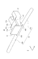
- FIG. 2 is a perspective view of the bead guide 30 according to this embodiment, showing the bead guide 30 shown in FIG. 1 in detail.
- FIG. 3 is a perspective view of the bead guide 30 of FIG. 2 from a direction different from that of FIG.
- the bead guide 30 of this embodiment includes a support portion 31 , a rod portion 32 and a height adjustment portion 33 .
- the support portion 31 is made of the same resin as the rod-shaped portion 32, and the support portion 31 and the rod-shaped portion 32 are integrally formed. Furthermore, the height adjusting portion 33 is also made of the same resin as the supporting portion 31 and the rod-shaped portion 32 and is formed integrally with the supporting portion 31 and the rod-shaped portion 32 .
- Z in FIGS. 2 and 3 indicates the height direction of the bead guide 30.
- X indicates the width direction of the support portion 31 of the bead guide 30 .
- Y is a direction orthogonal to the height direction Z and the width direction X, and is the radial direction of the conveying belt 12 when the bead guide 30 is installed on the conveyor base 14 .
- the support part 31 is fixed to the conveyor base 14 .
- the support portion 31 has a fixing portion 31a fixed to the conveyor base 14 on one end side, and a frame portion 31c integrally formed with the fixing portion 31a on the other end side.
- the frame portion 31c is provided with a pair of side plate portions 31e and 31f whose ends are formed integrally with the fixed portion 31a and opposed to each other, and a tip plate portion 31g that connects the tips of the side plate portions 31e and 31f.
- the side plate portions 31e and 31f and the tip plate portion 31g are arranged in a U shape in a plan view, and the region surrounded by the fixing portion 31a, the side plate portions 31e and 31f, and the tip plate portion 31g has a thickness. is provided with an opening 31b passing through.
- the fixed portion 31 a of the support portion 31 fixed to the conveyor base 14 may be provided with a concave portion or the like for fixing to the conveyor base 14 .
- the supporting portion 31 extends from a fixing portion 31a fixed to the conveyor base 14 to a frame portion 31c extending from the outer peripheral edge portion of the conveying belt 12 to the inner peripheral side.
- the frame portion 31c is configured to extend.
- the entire supporting portion 31 is integrally molded with resin and is provided with the opening portion 31b, for example, an external force applied to the rod-shaped portion 32 causes the rod-shaped portion 32 to move.
- an external force applied to the rod-shaped portion 32 causes the rod-shaped portion 32 to move.
- the shapes of the frame portion 31c and the opening portion 31b can be appropriately deformed, and the rod-like portion 32 can be brought into uniform contact with the bead 12b of the conveying belt 12. As shown in FIG.
- the height adjustment portion 33 is formed in a plate shape from the same resin as the support portion 31 and the rod-shaped portion 32, and is integrally formed with the tip plate portion 31g of the support portion 31 and the rod-shaped portion 32.
- the height adjusting portion 33 is provided to support the outer cover.
- the height adjusting portion 33 according to the present embodiment has a planar wall surface 33a including the height direction Z and the width direction X, and from the wall surface 33a to the peripheral surface of the bar-shaped portion 32 is formed flat through the connecting portion 33b.
- the connecting portion 33b is provided between the wall surface 33a and the peripheral surface of the rod-shaped portion 32, and eliminates a step between the wall surface 33a and the peripheral surface of the rod-shaped portion 32 to separate the wall surface 33a and the peripheral surface of the rod-shaped portion 32. flattening.
- the bar-shaped part 32 is formed in a round bar shape, is integrally formed with the support part 30 , and is supported by the support part 31 .
- the bar-shaped portion 32 extends from the side (frame portion 31c) of the support portion 31 farther from the fixed portion 31a fixed to the conveyor base 14 along the outer peripheral portion of the conveyor belt 12 in one direction of the outer peripheral portion. and a second rod-shaped portion 32b formed to extend in the other direction opposite to the one direction along the outer peripheral edge of the conveying belt 12.
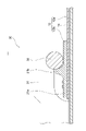
- FIG. 4 is a sectional view across the vicinity of the bead guide 30 of the curved belt conveyor 1 of FIG.
- a conveyor belt 12 is supported on a conveyor base 14 .
- the conveying belt 12 includes a belt body 12a and beads 12b.
- the belt main body 12a is formed by processing a sheet made of canvas such as polyester as a core and a conveying surface made of thermoplastic polyurethane or the like into an endless belt.
- the bead 12b has a plate-like portion 21a and a wall-like thick portion 21b.
- the bead 12b is made of a synthetic resin material such as polyamide resin.
- the bead 12b is attached by sewing along the outer peripheral edge of the conveying belt 12 or the like.
- FIG. 5 is a side view of the bead guide 30 of the curved belt conveyor 1 of FIG.
- FIG. 5 is a side view of the bead guide 30 attached to the conveying belt 12 provided parallel to the XY plane as seen from the Y direction.
- the direction perpendicular to the upper surface of the conveying belt 12 is the Z direction.
- the position (height) in the Z direction of the root portion 32aA supported by the support portion 31 of the first rod-shaped portion 32a is H1 with respect to the position (height) in the Z direction of the upper surface of the conveyor belt 12.
- the position (height) in the Z direction of the tip portion 32aB of the first rod-shaped portion 32a is indicated by H2.
- the first bar-shaped part 32a is arranged such that the height of the tip part 32aB is higher than the height of the root part 32aA, and the height of the transport belt 12 increases as it goes from the base part 32aA to the tip part 32aB. gradually tilts away from That is, it is preferable that the first rod-shaped portion is inclined so that the distance from the conveying belt 12 to the tip portion 32aB is greater than the distance from the conveying belt 12 to the root portion 32aA. Thereby, the stability of the circumferential movement of the transport belt 12 can be enhanced.
- FIG. 5 shows the first rod-shaped portion 32a, the same applies to the second rod-shaped portion 32b.
- FIG. 6 is a plan view of the bead guide 30 of the curved belt conveyor 1 of FIG.
- FIG. 6 is a plan view of the bead guide 30 attached to the conveying belt 12 provided parallel to the XY plane as viewed from the Z direction.
- the bar-shaped portion 32 is, for example, curved along the outer peripheral edge of the conveying belt 12 (curved with a curvature along the outer peripheral edge).
- the curvature 32R of the rod-shaped portion 32 is larger than the curvature 12R of the outer peripheral edge of the conveying belt 12. It is preferably smaller than the radius of curvature of the peripheral portion. Thereby, the stability of the circumferential movement of the transport belt 12 can be enhanced.
- the rod-shaped portion 32 is provided so that at least a portion of it contacts the inner peripheral side surface of the bead 12b.
- the bar-shaped portion 32 has, for example, a shape of a round bar in which only a short range of the end portion is tapered, and is formed in an arc shape with a radius of curvature that abuts on the inclined surface on the inner peripheral side of the thick portion 21b. .
- the supporting portion 31, the height adjusting portion 33 and the rod-shaped portion 32 are made of resin.
- the resin constituting the support portion 31, the height adjustment portion 33 and the rod-shaped portion 32 includes fluorine-containing polyacetal (polyoxymethylene: POM), silicon-containing POM, polyphenylene sulfide, polyamide made of hexamethylenediamine and adipic acid, and the like. Polyamide or the like can be used, and fluorine-containing POM is particularly preferably used from the viewpoint of abrasion resistance.
- bead guide 30 can be manufactured by, for example, injection molding, there is no need to assemble the parts. .
- the rod-shaped portion 32 contacting the bead 12b is made of resin. Since the rod-shaped portion 32 can move more flexibly than before according to the applied external force, the load applied from the bead 12b can be reduced at the rod-shaped portion 32, and abrasion powder is generated at the contact point with the bead 12b. sliding resistance can be reduced.
- the rod-shaped portion 32 made of resin of the bead guide 30 is flexibly movable in response to the external force applied from the bead 12b, the rod-shaped portion 32 can be brought into uniform contact with the bead 12b. Inward movement can be reliably prevented.
- a rod-shaped base body made of a metal such as stainless steel is coated with Teflon (registered trademark) on the surface of the rod-shaped base body, and a resin layer is formed on the surface of the rod-shaped base body.
- Teflon registered trademark
- Bead guides having portions have been considered.
- the resin layer of the rod-shaped portion coated with grease is brought into contact with the bead 12b and slid, thereby suppressing the inward movement of the conveying belt 12 during operation of the conveyor.
- a rod-shaped portion, a metal plate height adjustment portion, and a resin support portion are separately configured. work was required to assemble the
- the bead guide 30 since the entire inside of the rod-shaped portion 32 is made of resin, it is more flexible than the conventional rod-shaped portion provided with a metal rod-shaped base body inside.
- the rod-like portion 32 moves in response to the external force applied from the bead 12b during conveyor operation, thereby reducing the load applied from the bead 12b.
- the bead guide 30 according to the present embodiment can further reduce the generation of abrasion powder and the sliding resistance at the contact portion with the bead 12b as compared with the conventional one.
- the load on the motor for driving the conveying belt 12 can be reduced by the amount of the sliding resistance when the bar-shaped portion 32 slides on the bead 12b during the conveyor operation. Power consumption can be reduced.
- the frame portion 31c made of resin can be deformed according to the external force applied from the bead 12b via the rod-like portion 32, thereby Since the applied load can be further reduced, it is possible to correspondingly reduce the generation of abrasion powder and the sliding resistance at the contact portion with the bead 12b.
- the support portion 31, the rod-shaped portion 32, and the height adjustment portion 33 are integrally molded with resin, thereby eliminating the conventional assembly work. It is possible to reduce the burden on the worker during installation.
- the support portion 31, the rod-shaped portion 32, and the height adjustment portion 33 are integrally molded with resin, so that the number of parts can be reduced, and the cost can be reduced accordingly. can be planned.
- Example 1 a test plate material (50 mm long, 50 mm wide, 50 mm thick) made of polyphenylene sulfide resin (PPS: Poly Phenylene Sulfide Resin) (manufactured by DIC Corporation, product name: FZL-4033) was prepared.
- PPS Poly Phenylene Sulfide Resin
- Example 2 a test plate material (50 mm long, 50 mm wide, 50 mm thick) made of fluorine-containing POM (polyacetal) (manufactured by Mitsubishi Engineering-Plastics Co., Ltd., product name FL2020) was prepared.
- Example 3 a test plate material (50 mm long, 50 mm wide, 50 mm thick) made of POM containing silicon (manufactured by Mitsubishi Engineering-Plastics Corporation, product name: FL2022) was prepared.
- a rod-shaped portion of a conventional bead guide was prepared by coating a rod-shaped stainless steel rod-shaped portion base having a diameter of ⁇ of 8 mm with polytetrafluoroethylene.
- Examples 1 to 3 and Comparative Example 1 were slid on nylon (manufactured by Toray Industries, Inc., product name CM3003G1000) at a sliding speed of 5 mm/s and a load of 4.9 N using a Haydon surface property measuring instrument. Each dynamic friction coefficient at that time was measured.
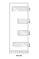
- FIG. 7 is a graph showing the measurement results of the dynamic friction coefficient obtained as a result. As shown in FIG. 7, the dynamic friction coefficient of Example 1 was 0.15, the dynamic friction coefficient of Example 2 was 0.10, and the dynamic friction coefficient of Example 3 was 0.10. On the other hand, the dynamic friction coefficient of Comparative Example 1 was 0.16. The dynamic friction coefficients of Examples 1 to 3 were smaller than that of Comparative Example 1, and in particular, Examples 2 and 3 were the smallest.
- each cumulative wear amount was measured when the cutting edge of the tester was applied to Examples 1 to 3 and rotated.
- a load of 44 N is applied and the number of rotations is 60 rpm, and the blades of the testing machine are applied to Examples 1 to 3 to rotate 20 rotations in the forward and reverse directions alternately, for a total of 80 rotations.
- a total amount of wear was measured when 3 sets of tests were conducted.
- FIG. 8 is a graph showing the measurement results of the cumulative wear amount obtained as a result. As shown in FIG. 8, the cumulative wear amount of Example 1 is 18.8 mg, the cumulative wear amount of Example 2 is 8.8 mg, and the cumulative wear amount of Example 3 is 18.1 mg. there were. Among Examples 1 to 3, the cumulative wear amount of Example 2 was the smallest.
- Example 4 a bead guide (Example 4) was prepared in which a rod-like portion, a support portion, and a height adjusting portion were integrally molded with the same fluorine-containing POM as in Example 2 above.
- a conventional bead guide comparativative Example 2 was prepared. Then, the bead guides of Example 4 and Comparative Example 2 were set in a curved belt conveyor for testing, and changes over time in the wear amount of the sliding portions of the beads and the bead guides during long-term operation were measured.
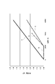
- FIG. 9 is a graph showing the change in wear amount over time, which is the measurement result.
- the vertical axis indicates the amount of wear (gf), and the horizontal axis indicates the operating time (h).
- the results of Example 4 are shown by straight lines ac.
- the results of Comparative Example 2 are indicated by straight line x.
- Example 4 as indicated by straight line a, the amount of wear was almost 0 during operation from 0 to 2,000 hours, and as indicated by straight line b, the amount of wear was 0.7 gf during operation from 2,000 to 4,000 hours, which is indicated by straight line c.
- the wear amount was 1.0 gf after 2000 to 6000 hours of operation.
- Comparative Example 2 as indicated by the straight line x, the wear amount was 1.8 gf during operation from 0 to 6000 hours. It was confirmed that the wear amount of Example 4 was smaller than that of Comparative Example 2.
- FIG. 10 is a graph showing the measurement results of changes in current value over time, where the vertical axis indicates current value (A) and the horizontal axis indicates operating time (h).
- the results of Example 4 are shown in graphs ac.
- the results of Comparative Example 2 are shown by graph x.
- the current values in all of graphs a to c were smaller than graph x in Comparative Example 2.
- the bead guide 30 is formed flat without a step between the peripheral surface of the rod-shaped portion 32 and the wall surface 33a of the height adjusting portion 33. is applied, the present invention is not limited to this.
- a bead guide according to another embodiment for example, as shown in FIG. good too.
- the bead guide 30X has a configuration in which a support portion 31X, a rod-shaped portion 32X, and a height adjustment portion 33X are integrally molded with resin.
- this support portion 31X also has a fixed portion 31Xa fixed to the conveyor base 14 and a frame portion 31Xc integrally formed with the fixed portion 31Xa, as in the above-described embodiment.
- the frame portion 31Xc is provided with a pair of side plate portions 31Xe and 31Xf whose ends are integrally formed with the fixed portion 31Xa and opposed to each other, and a tip plate portion 31Xg that connects the tips of the side plate portions 31Xe and 31Xf.
- the side plate portions X31e and 31Xf and the tip plate portion 31Xg are arranged in a U shape in plan view, and the region surrounded by the fixing portion 31Xa, the side plate portions 31Xe and 31Xf, and the tip plate portion 31Xg has a thickness An opening 31Xb penetrating through is provided.
- the rod-shaped portion 32X is integrally molded with the support portion 31X configured as described above, and is supported by the support portion 31X.
- the rod-shaped portion 32X has a first rod-shaped portion 32Xa extending in one direction along the outer peripheral edge of the conveyor belt 12 from one side plate portion 31Xf of the frame portion 31Xc, and the other side plate portion of the frame portion 31Xc. From 31Xe, it also has a second rod-shaped portion 32Xb extending along the outer peripheral edge of the conveying belt 12 in the other direction opposite to the one direction.
- the rod-shaped portion 32 extends from the end of the support portion 31 in one direction and the other direction along the outer peripheral edge of the conveyor belt 12.
- a rod-shaped portion 32X is formed at a predetermined distance from a height adjustment portion 33X integrally formed with the tip plate portion 31Xg of the support portion 31X.
- a step is provided between the wall surface 33Xa of the .
- the rod-shaped portion 32X in contact with the bead 12b is made of resin, thereby reducing wear powder during conveyor operation. and the sliding resistance can be reduced more than before.
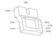
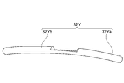
- rod-shaped portion is a bead guide made of resin, for example, as shown in FIGS. may be
- the support portion 31Y, the rod-shaped portion 32Y, and the height adjustment portion 33Y may all be made of resin. may be made of resin.
- the support portion 31Y, the rod-shaped portion 32Y, and the height adjustment portion 33Y may be made of the same resin, or may be made of different resins.
- the support portion 31Y and the height adjustment portion 33Y do not have to be made of resin.
- the support portion 31Y has a fixed portion 31Ya fixed to the conveyor base 14 and a frame portion 31Yc integrally formed with the fixed portion 31Ya.
- the frame portion 31Yc is provided with a pair of side plate portions 31Ye and 31Yf that are integrally formed with the fixed portion 31Ya and oppositely arranged at the ends thereof, and a tip plate portion 31Yg that connects the tips of the side plate portions 31Ye and 31Yf.
- the side plate portions Y31e and 31Yf and the tip plate portion 31Yg are arranged in a U shape in a plan view, and the region surrounded by the fixing portion 31Ya, the side plate portions 31Ye and 31Yf, and the tip plate portion 31Yg has a thickness.
- An opening 31Yb penetrating through is provided.
- the rod-shaped portion 32Y is attached to the attachment portion 31Yd of the support portion 31Y configured as described above.
- the support portion 31Y, the rod-shaped portion 32Y, and the height adjustment portion 33Y may be fixed to each other using screws or the like, or may be fixed using an adhesive or the like.
- At least the rod-shaped portions 32X and 32Y that contact the bead 12b are made of resin.
- the rod-shaped portions 32X and 32Y can move more flexibly than before according to the external force applied from the bead 12b, as in the above-described embodiment. can be reduced at the rod-shaped portions 32X and 32Y, and the generation of abrasion powder and the sliding resistance at the contact points with the beads 12b can be reduced accordingly.
- the case where the support portions 31, 31X, and 31Y provided with the frame portions 31c, 31Xc, and 31Yc forming the openings 31b, 31Xb, and 31Yb are applied as the support portions has been described.
- the invention is not limited to this, and for example, a supporting portion in which the insides of the openings 31b, 31Xb, and 31Yb are formed solid without providing the openings 31b, 31Xb, and 31Yb may be applied.
- the rod-shaped portion 32 in which the first rod-shaped portion 32a and the second rod-shaped portion 32b are formed symmetrically with respect to the support portion 31 was described, but the present invention is not limited to this.
- the rod-shaped portion may be such that the first rod-shaped portion and the second rod-shaped portion are formed asymmetrically with respect to 31 .
- the first rod-shaped portion 32Xa and the second rod-shaped portion 32Xb may be formed asymmetrically with respect to the support portion 31X.
- the two rod-shaped portions 32Yb may be formed asymmetrically with respect to the support portion 31Y.
- the present invention is not limited to this, and the support is provided without providing the height adjustment portion 33.
- a bead guide consisting of the portion 31 and the rod-shaped portion 32 may be applied.
- the bar-shaped portion 32 is integrally formed with the tip plate portion 31g of the support portion 31. As shown in FIG.
Landscapes
- Engineering & Computer Science (AREA)
- Mechanical Engineering (AREA)
- Framework For Endless Conveyors (AREA)
- Structure Of Belt Conveyors (AREA)
- Belt Conveyors (AREA)
Abstract
Description
(カーブベルトコンベヤ及びビードガイドの構成)
図1は、本実施形態に係るカーブベルトコンベヤ1の斜視図である。図1に示すように、本実施形態に係るカーブベルトコンベヤ1は、架台10と、2本のエンドローラ11,11と、搬送用ベルト12と、ビードガイド30とを含んで構成されている。カーブベルトコンベヤ1は、図示しない上流側のコンベヤと下流側のコンベヤとの間に設置され、上流側のコンベヤから搬送用ベルト12上に搬送物が送られ、当該搬送物を下流側のコンベヤへと円滑に受け渡す。
本実施形態のビードガイド30は、ビード12bに接触する棒状部32を樹脂で形成したことによって、コンベヤ運転時、棒状部32がビード12bに接触して摺動している際に、ビード12bから与えられた外力に応じて棒状部32が従来よりも一段と柔軟に可動できることから、ビード12bから与えられる負荷を棒状部32において低減でき、その分、ビード12bとの接触箇所における摩耗粉の発生と摺動抵抗とを低減することができる。
(動摩擦係数)
次に、ビードガイド30に用いる樹脂に関して動摩擦係数を測定した。ここでは、ビードガイド30の棒状部32に相当する試験用板材を、樹脂の種類等を変えて製造し、各試験用板材の動摩擦係数について測定した。
次に、ピコ摩耗試験機を使用して、上記の実施例1~3に試験機の刃物を当てて回転させたときの各累計摩耗量を測定した。ここでは、44Nの荷重を印加して60rpmの回転数で、実施例1~3を試験機の刃物を当てて回転させ、正方向及び逆方向に交互に20回転ずつ、総計で80回転を1セットとし、3セット試験を行ったときの累計の摩耗量を測定した。
次に、上記の実施例2と同じフッ素入りPOMにより棒状部と支持部と高さ調整部とを一体成形したビードガイド(実施例4)を用意した。また、金属製の棒状部基体をポリテトラフルオロエチレンで被覆した棒状部と、樹脂製の支持部と、金属製の高さ調整部とを別体とし、これらを組み立てた従来のビードガイド(比較例2)を用意した。そして、試験用のカーブベルトコンベヤに実施例4及び比較例2のビードガイドを設定し、長時間運転したときのビード及びビードガイドの摺動部分の摩耗量の時間変化を測定した。
次に、上述した実施例4及び比較例2のビードガイドについて、上記の摩耗量の時間変化の測定において、同時に電流値の時間変化についても測定したところ、図10に示すような結果が得られた。
なお、上述した実施形態においては、図2及び図3に示すように、棒状部32の周面と高さ調整部33の壁面33aとの間に段差がなく平面状に形成されたビードガイド30を適用した場合について述べたが、本発明はこれに限らない。他の実施形態に係るビードガイドとして、例えば、図11に示すように、棒状部32の周面と高さ調整部33の壁面33aとの間に段差が形成されたビードガイド30Xを適用してもよい。
上述した実施形態においては、ビードガイドとして、支持部31と棒状部32と高さ調整部33とが樹脂により一体成形されたビードガイド30を適用した場合について述べたが、本発明はこれに限らず、棒状部が樹脂からなるビードガイドであれば、種々の形状及び構成を有したビードガイドを適用してもよい。
10 架台
11 エンドローラ
12 搬送用ベルト
12a ベルト本体
12b ビード
14 コンベヤ基台
21a 板状部
21b 肉厚部
30 ビードガイド
31 支持部
31a 支持部本体
31b 開口部
32 棒状部
32a 第1棒状部
32b 第2棒状部
33 高さ調整部
Claims (8)
- 架台に設けられ、軸線が所定の角度で交差する2本のエンドローラと、前記2本のエンドローラの間に架け渡されて平面扇形となり、外周縁部にベルト位置決め用のビードが取り付けられた無端状の搬送用ベルトとを有するカーブベルトコンベヤにおいて、少なくとも一部が前記ビードに接触することで前記搬送用ベルトの位置決めをして前記搬送用ベルトの移動を抑制するビードガイドであって、
前記架台に対して固定される支持部と、
樹脂から形成されており、かつ、前記支持部に支持され、前記支持部から前記外周縁部に沿った方向に延伸し、少なくとも一部が前記ビードに接触するように設けられている棒状部と、
を備えた、ビードガイド。 - 前記支持部が前記棒状部と同一の樹脂で形成されており、前記支持部と前記棒状部とが一体に成形されている
請求項1に記載のビードガイド。 - 前記棒状部は、前記支持部に支持される根本部を有し、前記搬送用ベルトから先端部までの距離が、前記搬送用ベルトから前記根本部までの距離よりも大きくなるように傾いて構成されている
請求項1又は2に記載のビードガイド。 - 前記棒状部が前記外周縁部に沿って湾曲している
請求項1~3のいずれか1項に記載のビードガイド。 - 前記棒状部の湾曲の曲率が、前記搬送用ベルトの前記外周縁部の曲率よりも大きく構成されている
請求項4に記載のビードガイド。 - 架台に設けられ、軸線が所定の角度で交差する2本のエンドローラと、
前記2本のエンドローラの間に架け渡されて平面扇形となり、外周縁部にベルト位置決め用のビードが取り付けられた無端状の搬送用ベルトと、
ビードガイドと、を備え、
前記ビードガイドは、
前記架台に対して固定された支持部と、
樹脂から形成されており、かつ、前記支持部に支持され、前記支持部から前記外周縁部に沿った方向に延伸し、少なくとも一部が前記ビードに接触するように設けられている棒状部と、を有し、
少なくとも一部が前記ビードに接触することで前記搬送用ベルトの位置決めをして前記搬送用ベルトの移動を抑制する、
カーブベルトコンベヤ。 - 前記支持部が前記棒状部と同一の樹脂で形成されており、前記支持部と前記棒状部とが一体に成形されている
請求項6に記載のカーブベルトコンベヤ。 - 前記ビードは、板状部及び肉厚部を有しており、
前記棒状部が少なくとも前記肉厚部の側面に接触するように、前記ビードガイドが設けられている
請求項6又は7に記載のカーブベルトコンベヤ。
Priority Applications (2)
| Application Number | Priority Date | Filing Date | Title |
|---|---|---|---|
| KR1020237034853A KR20230156395A (ko) | 2021-03-17 | 2022-02-24 | 비드 가이드 및 커브 벨트 컨베이어 |
| CN202280018068.5A CN116940511A (zh) | 2021-03-17 | 2022-02-24 | 补强件导向器及弯道带式输送机 |
Applications Claiming Priority (2)
| Application Number | Priority Date | Filing Date | Title |
|---|---|---|---|
| JP2021044074A JP7839619B2 (ja) | 2021-03-17 | 2021-03-17 | ビードガイド及びカーブベルトコンベヤ |
| JP2021-044074 | 2021-03-17 |
Publications (1)
| Publication Number | Publication Date |
|---|---|
| WO2022196282A1 true WO2022196282A1 (ja) | 2022-09-22 |
Family
ID=83321295
Family Applications (1)
| Application Number | Title | Priority Date | Filing Date |
|---|---|---|---|
| PCT/JP2022/007689 Ceased WO2022196282A1 (ja) | 2021-03-17 | 2022-02-24 | ビードガイド及びカーブベルトコンベヤ |
Country Status (4)
| Country | Link |
|---|---|
| JP (1) | JP7839619B2 (ja) |
| KR (1) | KR20230156395A (ja) |
| CN (1) | CN116940511A (ja) |
| WO (1) | WO2022196282A1 (ja) |
Citations (3)
| Publication number | Priority date | Publication date | Assignee | Title |
|---|---|---|---|---|
| JP2002338023A (ja) * | 2001-05-11 | 2002-11-27 | Nitta Ind Corp | ビード付きコンベアベルト |
| JP2003128219A (ja) * | 2001-10-29 | 2003-05-08 | Nitta Ind Corp | 直線状ベルトコンベヤ |
| JP2007297154A (ja) * | 2006-04-28 | 2007-11-15 | Nitta Ind Corp | ベルト保持機構 |
Family Cites Families (7)
| Publication number | Priority date | Publication date | Assignee | Title |
|---|---|---|---|---|
| JP3752312B2 (ja) * | 1996-05-30 | 2006-03-08 | 日本コンベヤ株式会社 | ベルトコンベヤ用のトラフ形ローラ |
| JP3994374B2 (ja) | 2001-05-11 | 2007-10-17 | ニッタ株式会社 | カーブコンベア |
| JP5352105B2 (ja) | 2008-03-28 | 2013-11-27 | ニッタ株式会社 | カーブベルトコンベヤ |
| DE102008064641A1 (de) * | 2008-05-21 | 2010-01-21 | Interroll Holding Ag | Bandförderer |
| JP5670101B2 (ja) | 2010-05-31 | 2015-02-18 | 三ツ星ベルト株式会社 | カーブベルトコンベヤ |
| CN203047983U (zh) * | 2012-12-28 | 2013-07-10 | 河南科隆集团有限公司 | 一种气垫带式输送机上的变向转弯装置 |
| CN210619242U (zh) * | 2019-09-27 | 2020-05-26 | 上海尼尔机械制造有限公司 | 一种生产流水线用转弯输送机 |
-
2021
- 2021-03-17 JP JP2021044074A patent/JP7839619B2/ja active Active
-
2022
- 2022-02-24 WO PCT/JP2022/007689 patent/WO2022196282A1/ja not_active Ceased
- 2022-02-24 CN CN202280018068.5A patent/CN116940511A/zh active Pending
- 2022-02-24 KR KR1020237034853A patent/KR20230156395A/ko active Pending
Patent Citations (3)
| Publication number | Priority date | Publication date | Assignee | Title |
|---|---|---|---|---|
| JP2002338023A (ja) * | 2001-05-11 | 2002-11-27 | Nitta Ind Corp | ビード付きコンベアベルト |
| JP2003128219A (ja) * | 2001-10-29 | 2003-05-08 | Nitta Ind Corp | 直線状ベルトコンベヤ |
| JP2007297154A (ja) * | 2006-04-28 | 2007-11-15 | Nitta Ind Corp | ベルト保持機構 |
Also Published As
| Publication number | Publication date |
|---|---|
| JP7839619B2 (ja) | 2026-04-02 |
| JP2022143522A (ja) | 2022-10-03 |
| CN116940511A (zh) | 2023-10-24 |
| KR20230156395A (ko) | 2023-11-14 |
Similar Documents
| Publication | Publication Date | Title |
|---|---|---|
| CN1093491C (zh) | 带装置 | |
| US8317014B2 (en) | Belt conveyor | |
| WO2022196282A1 (ja) | ビードガイド及びカーブベルトコンベヤ | |
| NL2014655B1 (en) | Deflection roller, use of said deflection roller and tire building machines comprising said deflection roller. | |
| US7591206B2 (en) | Stopper apparatus and robot | |
| JP7281292B2 (ja) | 搬送装置 | |
| CA1115232A (en) | Belt conveyor | |
| JP6785147B2 (ja) | 搬送装置 | |
| JP2017173749A (ja) | ベルト搬送装置、定着装置及び画像形成装置 | |
| JP7514925B2 (ja) | 複数の可撓性長尺物の搬送装置およびその作動方法 | |
| EP3358219A1 (en) | Sliding contact-type wave generator, strain wave gearing device, and wave-generating method | |
| JP2019059567A (ja) | ゴムストリップ搬送装置 | |
| JP2938544B2 (ja) | ベルトコンベヤのベルト案内装置 | |
| JP7401720B1 (ja) | カーブコンベア用ローラ、カーブコンベア及びカーブベルト | |
| JP2538837B2 (ja) | コンベアベルト保持機構 | |
| JP3227125B2 (ja) | カーブベルトコンベア | |
| EP1215327A2 (en) | Spreading roller for fabrics or the like | |
| US20070102864A1 (en) | Paper sheet take-out apparatus | |
| JP6704605B2 (ja) | しわ伸ばし装置 | |
| JP7050880B2 (ja) | 搬送装置 | |
| JP2534808Y2 (ja) | ベルト駆動装置 | |
| JP6403110B2 (ja) | 自動調芯プーリを備えたベルトコンベア | |
| US857771A (en) | Belt conveyer. | |
| NL2017855B1 (en) | Positioning and conveying device | |
| JPH04148746A (ja) | ベルト駆動装置 |
Legal Events
| Date | Code | Title | Description |
|---|---|---|---|
| 121 | Ep: the epo has been informed by wipo that ep was designated in this application |
Ref document number: 22771038 Country of ref document: EP Kind code of ref document: A1 |
|
| DPE1 | Request for preliminary examination filed after expiration of 19th month from priority date (pct application filed from 20040101) | ||
| WWE | Wipo information: entry into national phase |
Ref document number: 202280018068.5 Country of ref document: CN |
|
| ENP | Entry into the national phase |
Ref document number: 20237034853 Country of ref document: KR Kind code of ref document: A |
|
| WWE | Wipo information: entry into national phase |
Ref document number: 1020237034853 Country of ref document: KR |
|
| NENP | Non-entry into the national phase |
Ref country code: DE |
|
| 122 | Ep: pct application non-entry in european phase |
Ref document number: 22771038 Country of ref document: EP Kind code of ref document: A1 |