WO2022196007A1 - 電力変換装置、制御方法、およびこれを用いた電力システム - Google Patents
電力変換装置、制御方法、およびこれを用いた電力システム Download PDFInfo
- Publication number
- WO2022196007A1 WO2022196007A1 PCT/JP2021/047110 JP2021047110W WO2022196007A1 WO 2022196007 A1 WO2022196007 A1 WO 2022196007A1 JP 2021047110 W JP2021047110 W JP 2021047110W WO 2022196007 A1 WO2022196007 A1 WO 2022196007A1
- Authority
- WO
- WIPO (PCT)
- Prior art keywords
- power
- alternator
- braking
- circuit
- terminal
- Prior art date
- Legal status (The legal status is an assumption and is not a legal conclusion. Google has not performed a legal analysis and makes no representation as to the accuracy of the status listed.)
- Ceased
Links
Images



Classifications
-
- H—ELECTRICITY
- H02—GENERATION; CONVERSION OR DISTRIBUTION OF ELECTRIC POWER
- H02P—CONTROL OR REGULATION OF ELECTRIC MOTORS, ELECTRIC GENERATORS OR DYNAMO-ELECTRIC CONVERTERS; CONTROLLING TRANSFORMERS, REACTORS OR CHOKE COILS
- H02P23/00—Arrangements or methods for the control of AC motors characterised by a control method other than vector control
- H02P23/20—Controlling the acceleration or deceleration
-
- H—ELECTRICITY
- H02—GENERATION; CONVERSION OR DISTRIBUTION OF ELECTRIC POWER
- H02P—CONTROL OR REGULATION OF ELECTRIC MOTORS, ELECTRIC GENERATORS OR DYNAMO-ELECTRIC CONVERTERS; CONTROLLING TRANSFORMERS, REACTORS OR CHOKE COILS
- H02P27/00—Arrangements or methods for the control of AC motors characterised by the kind of supply voltage
- H02P27/04—Arrangements or methods for the control of AC motors characterised by the kind of supply voltage using variable-frequency supply voltage, e.g. inverter or converter supply voltage
- H02P27/06—Arrangements or methods for the control of AC motors characterised by the kind of supply voltage using variable-frequency supply voltage, e.g. inverter or converter supply voltage using DC to AC converters or inverters
-
- H—ELECTRICITY
- H02—GENERATION; CONVERSION OR DISTRIBUTION OF ELECTRIC POWER
- H02P—CONTROL OR REGULATION OF ELECTRIC MOTORS, ELECTRIC GENERATORS OR DYNAMO-ELECTRIC CONVERTERS; CONTROLLING TRANSFORMERS, REACTORS OR CHOKE COILS
- H02P3/00—Arrangements for stopping or slowing electric motors, generators, or dynamo-electric converters
- H02P3/06—Arrangements for stopping or slowing electric motors, generators, or dynamo-electric converters for stopping or slowing an individual dynamo-electric motor or dynamo-electric converter
- H02P3/18—Arrangements for stopping or slowing electric motors, generators, or dynamo-electric converters for stopping or slowing an individual dynamo-electric motor or dynamo-electric converter for stopping or slowing an AC motor
- H02P3/22—Arrangements for stopping or slowing electric motors, generators, or dynamo-electric converters for stopping or slowing an individual dynamo-electric motor or dynamo-electric converter for stopping or slowing an AC motor by short-circuit or resistive braking
Definitions
- the present invention relates to power converters, control methods, and power systems.
- a dynamic brake circuit is used in an AC motor such as an AC motor to brake the rotational motion of its rotor.
- it is also proposed to monitor the voltage on the DC side of the power conversion device, and when the voltage reaches a preset level, input a failure signal and consume the regenerated power as heat by the semiconductor switch and the braking resistor. (Patent Document 1 below).
- Such a circuit that consumes regenerated power as heat on the DC side is also called a regenerative brake circuit.
- the dynamic brake circuit has a switch for short-circuiting or grounding the AC terminals of the AC machine with a resistor.
- Dynamic braking circuits often use relays as switches in preparation for large currents. However, because the relay has mechanical contacts, it usually takes a long time to switch on, which often results in a long time to stop the alternator.
- the regenerative braking circuit since the regenerative braking circuit uses a semiconductor switch, it operates at high speed, but it does not reach the relay in terms of capacity. Also, frequent operation of the regenerative braking circuit poses a problem in terms of energy saving.
- the object of the present invention is to provide a technology that can quickly consume regenerative power, shorten the stop time of the AC machine, and achieve energy saving when an abnormality occurs in the AC machine.
- this power conversion device includes: an inverter circuit capable of converting DC power supplied to a DC terminal into AC power and supplying the AC power to an AC machine, and converting regenerative power generated by the AC machine into DC power and supplying the DC power to the DC terminal; a dynamic brake circuit capable of braking the alternator by short-circuiting an alternating current terminal connected to the alternator of the inverter circuit with a first resistor; a regenerative brake circuit capable of braking the alternator by short-circuiting the DC terminal of the inverter circuit with a second resistor; a control unit; When the dynamic brake circuit brakes the alternator, the controller further brakes the alternator by the regenerative brake circuit when a predetermined first condition is satisfied.
- the dynamic brake circuit is operated by, for example, a mechanical relay.
- the regenerative braking circuit is operated by, for example, a semiconductor switch.
- the control unit of this power converter applies braking to the alternator using the dynamic braking circuit, and further applies braking using the regenerative braking circuit. Therefore, the present power converter can apply braking to the alternator earlier than the dynamic brake circuit alone, and can stop the alternator in a short time.
- the control unit applies braking by the regenerative braking circuit when a predetermined first condition is satisfied when applying braking to the alternator by the dynamic braking circuit. Therefore, the control unit can operate the regenerative braking circuit as much as necessary to save energy.
- the first condition is, for example, the occurrence of an abnormality.
- the control unit can detect the occurrence of an abnormality by, for example, a signal from an abnormal stop button. Also, the control unit can detect the occurrence of an abnormality from, for example, sensors that measure the physical quantities of each unit, such as temperature, current, voltage, and number of rotations.
- the control unit causes the regenerative brake circuit to operate the AC machine when the terminal voltage of the DC terminal of the inverter circuit exceeds a first reference value in a state in which the AC machine is normal. Executes a process that applies braking to The first condition is that an abnormality occurs and the terminal voltage of the DC terminal of the inverter circuit exceeds a second reference value that is smaller than the first reference value. That is, when an abnormality occurs, the control unit activates the regenerative braking circuit when the terminal voltage of the DC terminal reaches the second reference value, which is lower than normal. Therefore, in the event of an abnormality, the control section can operate the regenerative braking circuit earlier.
- the first reference value is determined according to the rated withstand voltage of the capacitor C1, the voltage from the AC power supply input to the converter CV1, and the like.
- the second reference value should basically be set to a value higher than the instantaneous peak value of the input voltage from the AC power supply.
- the second reference value may be set to a value higher than the input voltage within the assumed usage range.
- the control unit may acquire the peak value of the input voltage of the AC power supply detected by the voltage sensor and actively set the second reference value.
- the control unit calculates an operating time corresponding to an amount of energy to be consumed by the regenerative brake circuit based on kinetic energy possessed by the alternator when an abnormality occurs in the alternator, The regenerative braking circuit is operated for the calculated operating time. Therefore, the control unit can operate the regenerative braking circuit within a necessary limit determined from the kinetic energy of the alternator when an abnormality occurs. As a result, the controller can save energy.
- the dynamic braking circuit comprises: a first dynamic brake circuit capable of braking the alternator with a resistor having a first resistance value; a second dynamic brake circuit capable of braking the alternator with a resistor having a second resistance value smaller than the first resistance value;
- the control unit further controls the alternator by a second dynamic brake circuit when a predetermined second condition is satisfied during execution of the process of braking the alternator by the first dynamic brake circuit.
- the first resistance value is determined according to the specifications of the dynamic brake circuit required for normal operation.
- the second resistance value is determined according to the specifications required for the dynamic brake circuit DB2 when the regenerated electric power from the AC machine is reduced. The specification is, for example, a time constant when regenerative energy is consumed.
- the control unit can stop the alternator in a short time by adding braking by the second dynamic brake circuit. Also, the control unit operates the second dynamic brake circuit only when the second condition is satisfied. Therefore, the control unit can operate the second dynamic brake circuit under more limited circumstances.
- the second condition is that a predetermined time has passed since the first dynamic brake circuit started braking, or that the rotation speed of the rotor of the alternator is equal to or less than a predetermined reference value.
- the control unit can operate the second dynamic brake circuit after a predetermined period of time has elapsed since the first dynamic brake circuit started braking, and the regenerated electric power from the AC machine has decreased. Further, when the rotation speed of the rotor of the AC machine becomes equal to or less than the predetermined reference value, the control unit can wait for the regenerative electric power from the AC machine to decrease before activating the second dynamic brake circuit.
- the predetermined time may be determined experimentally or empirically according to parameters such as the type of the AC machine, the type of abnormality, and the rotational energy accumulated in the rotor of the AC machine when the abnormality occurred.
- the reference value may also be determined experimentally or empirically according to parameters such as the type of AC machine, the type of abnormality, and the energy of rotational motion accumulated in the rotor of the AC machine when the abnormality occurs.
- the power converter is an inverter circuit capable of converting DC power supplied to a DC terminal into AC power and supplying the AC power to an AC machine, and converting regenerative power generated by the AC machine into DC power and supplying the DC power to the DC terminal; a first dynamic brake circuit capable of braking the alternator by short-circuiting an AC terminal connected to the alternator of the inverter circuit with a resistor having a first resistance value; a second dynamic brake circuit capable of braking the AC terminal of the inverter circuit connected to the AC machine by a resistor having a second resistance value smaller than the first resistance value, and a control unit; The control unit further controls the alternator by a second dynamic brake circuit when a predetermined second condition is satisfied during execution of the process of braking the alternator by the first dynamic brake circuit. Add braking.
- the controller can stop the alternator in a short period of time.
- the present embodiment is exemplified as a control method for a power converter.
- braking is applied to the alternator by a dynamic brake circuit;
- the regenerative braking circuit further brakes the alternator if the predetermined first condition is satisfied.
- the present embodiment is exemplified by a power system having a power converter and an alternator supplied with AC power from the power converter.
- the regenerative power when an abnormality occurs in the AC machine, the regenerative power can be consumed early, the stop time of the AC machine can be shortened, and energy saving can be achieved.
- FIG. 1 is a diagram illustrating a power converter to which a control circuit according to one embodiment is applied.
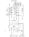
- FIG. 2 is a diagram illustrating the power conversion device of the first embodiment.
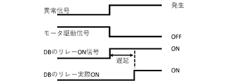
- FIG. 3 is a diagram illustrating a state of time delay due to relays.
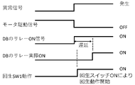
- FIG. 4 is a diagram illustrating processing of the control circuit of the first embodiment.
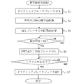
- FIG. 5 is a flowchart illustrating processing of the control circuit.
- FIG. 6 is a diagram illustrating the power conversion device of the second embodiment.
- FIG. 7 is a diagram illustrating processing of the control circuit of the second embodiment.
- FIG. 8 is a flowchart illustrating processing of the control circuit.
- this embodiment An embodiment (hereinafter also referred to as "this embodiment") according to one aspect of the present invention will be described below with reference to the drawings.
- this embodiment described below is merely an example of the present invention in every respect. It goes without saying that various modifications and variations can be made without departing from the scope of the invention. That is, in carrying out the present invention, a specific configuration according to the present embodiment may be employed as appropriate.
- FIG. 1 illustrates a power system including a power converter 1A according to this embodiment.
- This power system includes an AC power supply, a power converter 1A, and a load that receives power from the power converter 1A.
- the power conversion device 1A includes, for example, a control circuit 10, a converter CV1 that mutually converts AC power and DC power from an AC power supply, and a converter CV1 that converts the DC power output from the converter CV1 into AC power to power an AC motor or the like. It has inverters IV1 to IV6 that supply power to the AC machine and input regenerated power generated by the AC machine to the converter CV1.
- the control circuit 10 controls each part of the power converter 1A. Note that an AC power supply and an AC machine are omitted in FIG. In FIG. 1, a plurality of inverters IV1 and the like are connected in parallel to the DC side terminals (P, N) of the converter CV1.
- the number of inverters IV1 and the like and the number of AC machines fed from the inverter IV1 and the like are not limited to six. Each of these numbers may be one, or may be seven or more.
- an AC motor refers to a motor that inputs and outputs AC power to terminals, and includes, for example, a synchronous motor and an induction motor.
- FIG. 2 is a diagram illustrating the power conversion device 1 of the first embodiment.
- the power conversion device 1 has a converter CV1.
- Converter CV1 has a connector CNA with terminals L1, L2, L3 connected to a three-phase AC power supply.
- a filter F for removing high-frequency noise may be provided at the terminals L1, L2, and L3.
- the converter CV1 may have, for example, a bridge circuit that full-wave rectifies each phase of the three-phase AC circuit and a power factor correction circuit that improves the power factor of each phase of the three-phase AC circuit.
- Converter CV1 may also be a bridgeless power factor correction circuit.
- a smoothing capacitor C1 is provided between the terminals on the output side of the converter CV1 (the side opposite to the connector CNA).
- the terminal voltage on the output side of converter CV1 (the terminal voltage of capacitor C1) is also referred to as a DC output voltage.
- the DC output voltage is also called PN voltage or DC bus voltage.
- the converter CV1 converts the AC voltage from the AC power supply connected to the connector CNA side into a DC output voltage, converts the DC output voltage into a three-phase AC voltage, and can send it back to the AC power supply. good.
- a fuse is provided at the terminal on the output side of the converter CV1.
- the input terminal of the inverter IV1 is connected to the output side of the converter CV1.
- a regenerative brake circuit RB is connected in parallel to the capacitor C1 between the input terminals of the inverter IV1, with a configuration in which a regenerative resistor R1 and a switch SW1 are connected in series.
- the converter CV1 is a semiconductor switch, such as a transistor.
- Regenerative resistor R1 is an example of a second resistor. That is, it can be said that the regenerative brake circuit RB short-circuits the DC terminals of the inverter circuit by the second resistor.
- a bridge circuit BC is formed by six switch elements Q1 to Q6 between the input terminals of the inverter IV1.
- the six switch elements Q1, etc. have diodes in parallel with the path between the collector-emitter of the bipolar transistor and in the direction opposite to the direction from the collector to the emitter.
- MOSFETs may be used as the six switch elements Q1 and the like instead of the bipolar transistors.
- parasitic diodes of MOSFETs may be used as the diodes of the six switching elements Q1 and the like.
- a connection point between the emitter of the switch element Q1 and the collector of the switch element Q2 supplies the U-phase voltage of the three-phase AC circuit. That is, the switch element Q1 serves as a high-side switch of the upper arm of the inverter circuit that generates the U-phase voltage. Also, the switch element Q2 serves as a low-side switch for the lower arm of the inverter circuit that generates the U-phase voltage.
- connection point between the emitter of the switching element Q3 and the collector of the switching element Q4 supplies the V-phase voltage of the three-phase AC circuit. That is, the switch element Q3 serves as a high-side switch of the upper arm of the inverter circuit that generates the V-phase voltage. Also, the switch element Q4 serves as a low-side switch for the lower arm of the inverter circuit that generates the V-phase voltage.
- connection point between the emitter of the switching element Q5 and the collector of the switching element Q6 supplies the W-phase voltage of the three-phase AC circuit. That is, the switch element Q5 serves as a high-side switch of the upper arm of the inverter circuit that generates the W-phase voltage. Also, the switch element Q6 serves as a low-side switch for the lower arm of the inverter circuit that generates the W-phase voltage.
- the U-phase, V-phase, and W-phase on the output side of the inverter IV1 supply three-phase AC power to the load AC machine via the U-phase, V-phase, and W-phase terminals of the connector CNC. supply.
- a dynamic brake circuit DB is provided on each power path from each phase on the output side of the inverter IV1 to the U-phase terminal, V-phase terminal, and W-phase terminal of the connector CNC. That is, resistors RU, RV, and RW and relays SU, SV, and SW are connected in series in parallel with the load of each phase. As a result, the U-phase, V-phase, and W-phase circuits of the dynamic brake circuit DB are formed. That is, the circuits of the respective phases of the dynamic brake circuit DB are connected in parallel to the load connected to the connector CNC and the resistors RU, RV, RW are connected. is an example of the first resistor. That is, it can be said that the dynamic brake circuit DB short-circuits the AC terminals by the first resistors (resistors RU, RV, RW).
- the control circuit 10 controls the converter CV1 and the inverter IV1. That is, during power running operation, the control circuit 10 converts the three-phase AC power into DC power by the converter CV1, converts the DC power into three-phase AC power by the inverter IV1, and supplies the power to the AC machine connected to the connector CNC. supply power.
- control circuit 10 may be provided by a central processing unit (CPU) and a main storage device such as memory. That is, one or a plurality of CPUs may execute the processing of the control circuit 10 by a computer program developed on a memory so as to be executable.
- CPU central processing unit
- main storage device such as memory. That is, one or a plurality of CPUs may execute the processing of the control circuit 10 by a computer program developed on a memory so as to be executable.
- a CPU is also called a processor.
- the CPU is not limited to a single processor, and may have a multiprocessor configuration. Also, a single CPU may have a multi-core configuration.
- the main memory stores computer programs executed by the CPU, data processed by the CPU, and the like.
- the control circuit 10 may include a Digital Signal Processor (DSP), a Graphics Processing Unit (GPU), etc., and the CPU may cooperate with these processors.
- the main memory is Dynamic Random Access Memory (DRAM), Static Random Access Memory (SRAM), Read Only Memory (ROM), or the like.
- control circuit 10 may include an Analog-to-Digital (AD) converter, a Digital-to-Analog (DA) converter, other digital circuits, and analog circuits.
- AD Analog-to-Digital
- DA Digital-to-Analog
- control circuit 10 When an abnormality occurs in the AC machine, control circuit 10 cuts off power supply from converter CV1 and inverter IV1. However, at this time, the rotor of the AC machine continues to rotate, and the energy of this rotation generates regenerated electric power.
- the control circuit 10 turns on the relays SU, SV, and SW of each phase of the dynamic brake circuit DB in order to consume the regenerated electric power in a short period of time and stop the rotational motion.
- the U-phase terminal, V-phase terminal, and W-phase terminal of connector CNC are short-circuited by resistors RU, RV, and RW of dynamic brake circuit DB.
- the regenerated power from the alternator supplied to the U-phase terminal, V-phase terminal, and W-phase terminal is consumed as heat.
- Fig. 3 shows an example of the time delay situation due to the relay.
- the control circuit 10 cuts off the motor drive signal and operates the dynamic brake circuit DB in order to stop the rotation of an AC machine such as an AC motor in a short period of time.
- the control circuit 10 causes the resistors RU, RV, and RW of the dynamic brake circuit DB to absorb the regenerated electric power via the relays SU, SV, and SW, thereby starting the motor in as short a time as possible. try to stop.
- the relays SU, SV, and SW there is a delay from when the drive signal is received until the switch contacts are turned on.
- the time until the AC motor or the like stops is sufficiently short.
- the opening/closing time until the open contact closes is several 10 ms to 100 ms.
- the control circuit 10 turns on the switch SW1 of the regenerative brake circuit RB to short-circuit the output DC voltage through the regenerative resistor R1.
- the control unit 10 can detect the occurrence of an abnormality, for example, by a signal from an abnormality stop button provided on the power conversion device 1 or the alternator.
- the control unit 10 can detect the occurrence of an abnormality from, for example, sensors that measure the physical quantities of each unit, such as temperature, current, voltage, and number of revolutions.
- FIG. 4 illustrates the processing of the control circuit 10 of this embodiment.
- the control circuit 10 cuts off the drive signal for the alternator, and operates the regenerative braking circuit RB after issuing an operation command for the dynamic braking circuit DB. More specifically, the control circuit 10 turns on the switch SW1 of the regenerative brake circuit RB for system protection when the terminal voltage of the capacitor C1, that is, the DC output voltage reaches the operating threshold (regeneration ON threshold). . Then, the regenerative braking circuit RB is activated first before the relays SU, SV, and SW are actually turned on due to the time delay. Furthermore, in the present embodiment, the operating threshold (regeneration ON threshold) of the regenerative brake circuit RB is set lower than usual.
- the control circuit 10 operates the regenerative braking circuit RB earlier.
- the operating threshold of the regenerative brake circuit RB is usually set as high as possible so as to approach the breakdown voltage rating of the smoothing capacitor C1.
- the regenerative braking circuit RB is turned on before the contact of the relay of the dynamic braking circuit DB is turned on.
- the switch SW1 of the regenerative brake circuit RB is a semiconductor switch such as a bipolar transistor or a MOSFET (unipolar transistor), and has a shorter operation delay time than the relays SU, SV, and SW. With such processing, the regenerative energy of the AC machine is absorbed early, and the stop time of the AC motor and the like is shortened.
- control circuit 10 may calculate the motor power immediately before stopping and determine the maximum ON time of the regenerative braking circuit RB. This is to shorten the operation time of the regenerative braking circuit RB as much as possible.
- control circuit 10 may send part of the power charged in capacitor C1 back to the AC power supply side through converter CV1.
- FIG. 5 is a flowchart illustrating the processing of the control circuit 10.
- FIG. This process is executed when an abnormality occurs in either the load alternator or the power converter 1 and the power supply to the alternator is interrupted. This processing is referred to as post-abnormality detection processing.
- the control circuit 10 first transmits a control signal for turning on the dynamic brake circuit DB to the relay SU of the dynamic brake circuit DB (S1).
- the control circuit 10 acquires the operating threshold value E0 of the regenerative braking circuit RB at the time of abnormality detection from a predetermined address of the main storage device (S2).
- the operating threshold E0 is a value lower than the operating threshold of the regenerative braking circuit RB in the normal state.
- the operating threshold E0 is determined with a view to early shutdown of the alternator of the load and is set to a predetermined address in the main memory.
- the operating threshold E0 is set to be higher than the input voltage within the expected usage range, and is stored at a predetermined address in the main memory.
- the control circuit 10 can also detect the peak value of the input voltage of the AC power source detected by the voltage sensor, actively set the operating threshold value E0, and store it at a predetermined address in the main memory device. .
- the term "experimental" naturally includes computer simulation.
- the operating threshold E0 is an example of a second reference value smaller than the first reference value.
- the operating threshold value of the regenerative braking circuit RB in the normal state is an example of the first reference value.
- the control circuit 10 calculates the ON time DT of the regenerative brake circuit RB (S3).
- the ON time DT of the regenerative braking circuit RB is composed of the regenerative electric power predicted to be generated from the kinetic energy calculated from the current rotation speed of the AC machine, for example, the AC motor, the operation delay time TX of the relay SU and the like, and the It is determined based on the relationship between the regenerative power to be consumed during the period of the operation delay time and the like. For example, if the regenerative braking circuit RB needs to operate for a period shorter than the operation delay time TX of the relay SU or the like, the ON time DT of the regenerative braking circuit RB is set shorter than the operation delay time TX.
- the ON time DT of the regenerative braking circuit RB should match the operation delay time TX of the relay SU or the like. good. That is, when the dynamic braking circuit DB is turned on, the regenerative braking circuit RB may be turned off.
- the ON time DT can be said to be an example of an operating time corresponding to the amount of energy to be consumed by the regenerative braking circuit. It can be said that the kinetic energy calculated from the current rotation speed of the AC motor is an example of the kinetic energy possessed by the AC machine.
- the control circuit 10 determines whether or not the DC voltage (the terminal voltage of the capacitor C1) charged by the regenerative power exceeds the operating threshold E0 (S4).
- the control circuit 10 turns on the regenerative brake circuit RB for the ON time DT (S5).
- the switch SW1 is turned on, and the DC power is consumed by the regenerative resistor R1 for the time DT.
- the condition under which S4 is determined to be affirmative can be said to be the first condition.
- the process of S5 is executed when an abnormality occurs in either the load alternator or the power conversion device 1 . Therefore, it can be said that the first condition is when an abnormality occurs and the terminal voltage of the DC terminal of the inverter circuit exceeds a second reference value (operation threshold value E0) that is lower than the first reference value.
- the control circuit 10 determines whether or not the system has been stopped (S6). Stopping the system means stopping the rotation of the load alternator. When the system stop is completed (YES in S6), the control circuit 10 transmits a control signal to turn off the dynamic brake circuit DB to the relay SU of the dynamic brake circuit DB, etc., and terminates the process.
- the control circuit 10 turns on the regenerative braking circuit RB together with the command to turn on the dynamic braking circuit DB. Therefore, even if an operation delay time occurs in the relay SU of the dynamic brake circuit DB, the power conversion device 1 quickly consumes the regenerative energy of the load AC machine, for example, the AC motor, and the AC machine can be stopped.
- the control circuit 10 monitors the DC output voltage (PN voltage) across the capacitor C1 of the DC circuit charged by the regenerative power, and when the DC output voltage exceeds the operating threshold E0, the regenerative braking circuit RB to turn on. Therefore, the regenerative braking circuit RB does not operate during the period when the DC output voltage does not exceed the operating threshold value E0, so that the power converter 1 can avoid wasteful power consumption.
- the operating threshold E0 is set to a value lower than the operating threshold of the regenerative braking circuit RB in the normal state. Therefore, the control circuit 10 can control the operation of the regenerative braking circuit RB to be suppressed in a normal state and to operate the regenerative braking circuit RB when an abnormality occurs. As a result, the control circuit 10 can suppress wasteful power consumption when no abnormality occurs, and can effectively operate the regenerative braking circuit RB only when an abnormality occurs.
- control circuit 10 determines the ON time DT of the regenerative braking circuit RB based on the kinetic energy of the alternator when the power is cut off. Therefore, the control circuit 10 can operate the regenerative braking circuit RB to the extent necessary to quickly stop the load alternator.
- FIG. 6 is a diagram illustrating the power conversion device 1B of this embodiment.
- the power conversion device 1B is the same as the power conversion device 1 of FIG. 2 except that it has two dynamic brake circuits DB1 and DB2.
- the power conversion device 1B has a control circuit 10B.
- the control circuit 10B is the same as the control circuit 10 of the first embodiment except that it controls two dynamic brake circuits DB1 and DB2.
- the dynamic brake circuit DB1 is an example of a first dynamic brake circuit
- the dynamic brake circuit DB2 is an example of a second dynamic brake circuit.
- the dynamic brake circuit DB1 has the same configuration as the dynamic brake circuit DB in FIG. That is, the dynamic brake circuit DB1 connects resistors RU, RV, and RW and relays SU, SV, and SW in series to form U-phase, V-phase, and W-phase circuits, respectively. Each phase circuit of the dynamic brake circuit DB is connected in parallel to a load connected to the connector CNC.
- the configuration of the dynamic brake circuit DB2 is also similar to that of the dynamic brake circuit DB1. That is, the dynamic brake circuit DB2 has relays SU2, SV2, and SW2 for the U-phase, V-phase, and W-phase, respectively. However, the dynamic braking circuit DB2 has a resistance in each phase that is smaller than the resistances RU, RV, and RW in each phase of the dynamic braking circuit DB1. Therefore, in FIG. 6, the resistor of the dynamic braking circuit DB2 is omitted. Therefore, the dynamic braking circuit DB2 can consume regenerative power in a short time with a small time constant.
- the resistor of the dynamic brake circuit DB2 can be said to have a second resistance value smaller than the first resistance value.
- the first resistance value is determined according to the specifications of the dynamic brake circuit DB1 required for normal operation.
- the first resistance value may be determined experimentally or empirically.
- the second resistance value is determined according to the specifications required for the dynamic brake circuit DB2 when the regenerated electric power from the alternator is reduced. The specification is, for example, a time constant when regenerative energy is consumed.
- the second resistance value may be determined experimentally or empirically.
- FIG. 7 illustrates the processing of the control circuit 10B of this embodiment.
- the control circuit 10B When the alternator, which is the load, stops abnormally, the control circuit 10B first turns on the dynamic brake circuit DB1 and then turns on the dynamic brake circuit DB2.
- the control circuit 10B turns on the dynamic brake circuit DB1 after a predetermined period of time has passed after turning on the dynamic brake circuit DB1.
- the control circuit 10B turns on the dynamic brake circuit DB2 when the rotation speed of the alternator becomes equal to or less than a predetermined rotation speed.
- FIG. 8 is a flowchart illustrating the processing of the control circuit 10B.
- this processing processing after abnormality detection
- the control circuit 10B first transmits a control signal for turning on the dynamic brake circuit DB1 to the relay SU of the dynamic brake circuit DB1 (S11).
- the control circuit 10B determines whether or not a predetermined condition is satisfied (S12).
- the predetermined condition is an example of the second condition, and is that a predetermined time has elapsed after the dynamic brake circuit DB1 is controlled to be turned on. That is, it can be said that the predetermined condition is that a predetermined period of time has elapsed since the first dynamic braking circuit was instructed to start braking.
- the predetermined time may be determined experimentally or empirically according to parameters such as the type of the AC machine, the type of abnormality, and the rotational energy accumulated in the rotor of the AC machine when the abnormality occurred. Further, the predetermined condition may be that the rotation speed of the AC machine has become equal to or less than a predetermined rotation speed.
- the predetermined condition is that the rotation speed of the rotor of the AC machine is equal to or less than a predetermined reference value.
- This reference value may also be determined experimentally or empirically according to parameters such as the type of AC machine, the type of abnormality, and the energy of rotational motion accumulated in the rotor of the AC machine when the abnormality occurs.
- the control circuit 10B transmits a control signal for turning on the dynamic brake circuit DB2 to the relay SU2 of the dynamic brake circuit DB2 and the like (S13). Then, the control circuit 10B determines whether or not the system stop has been completed (S14). When the system is completely stopped (YES in S14), the control circuit 10 transmits a control signal for turning off the dynamic brake circuits DB1 and DB2 to the dynamic brake circuits DB1 and DB2, and ends the process (S15).
- the control circuit 10B can consume regenerative power by using a resistor with a high resistance value to suppress the current value in a region where regenerative energy is large. Then, in a region where the regenerative energy is small, the control circuit 10B uses a resistor with a low resistance value to reduce the time constant, thereby consuming the regenerative power in a short period of time. That is, the power conversion device 1B can consume regenerative power in a short period of time by using the two dynamic brake circuits DB1 and DB2 each having two types of large and small resistances.
- the regenerative braking circuit RB may be used together with the dynamic braking circuits DB1 and DB2 of the second embodiment. Further, in the first embodiment and the second embodiment, the power converters 1, 1A, 1B, etc. in the three-phase AC circuit are illustrated. However, practice of the present invention is not limited to three-phase AC circuits. That is, the control of the regenerative brake circuit RB, the dynamic brake circuits DB, DB1, DB2, etc. by the control circuits 10, 10B, etc., can also be performed in a single-phase AC circuit.
- ⁇ Appendix> 1. an inverter circuit (IV1) capable of converting DC power supplied to a DC terminal into AC power and supplying the AC power to an AC machine, and converting regenerative power generated by the AC machine into DC power and supplying the DC power to the DC terminal; , A dynamic brake circuit capable of braking the AC machine by short-circuiting the AC terminals (U, V, W) connected to the AC machine of the inverter circuit (IV1) by means of first resistors (RU, RV, RW).
- DB, DB1, DB2 a regenerative brake circuit capable of braking the alternator by short-circuiting the DC terminal of the inverter circuit (IV1) with a second resistor (R1);
- a control unit (10, 10B) The control unit (10, 10B) further controls the regenerative braking circuit (RB) when a predetermined first condition is satisfied when braking the alternator by the dynamic braking circuit (DB, DB1).
Landscapes
- Engineering & Computer Science (AREA)
- Power Engineering (AREA)
- Stopping Of Electric Motors (AREA)
- Control Of Ac Motors In General (AREA)
- Inverter Devices (AREA)
Abstract
電力変換装置は、直流端子に供給される直流電力を交流電力に変換して交流機に供給するとともに、交流機で発生した回生電力を直流電力に変換して直流端子へ供給可能なインバータ回路と、インバータ回路の交流機に接続される交流端子を第1の抵抗により短絡することで交流機を制動可能なダイナミックブレーキ回路と、インバータ回路の直流端子を第2の抵抗により短絡することで交流機を制動可能な回生ブレーキ回路と、制御部と、を備え、ダイナミックブレーキ回路により交流機に制動を加えるときに、所定の第1条件が充足されている場合にさらに回生ブレーキ回路により交流機に制動を加える。
Description
本発明は、電力変換装置、制御方法、および電力システムに関するものである。
交流電動機等の交流機には、その回転子の回転運動の制動のため、ダイナミックブレーキ回路が用いられる。また、例えば、電力変換装置の直流側の電圧を監視し、電圧が予め設定されたレベルに到達した時点で、故障信号の入力により半導体スイッチと制動抵抗により回生電力を熱として消費することも提案されている(下記特許文献1)。このような直流側で回生電力を熱として消費する回路は、回生ブレーキ回路とも呼ばれる。
ダイナミックブレーキ回路は、交流機の交流端子を抵抗で短絡または接地するためのスイッチを有する。ダイナミックブレーキ回路では、大電流に備え、スイッチとしてリレーを用いることが多い。しかし、リレーは機械式接点を有するため、通常はスイッチオンの時間を要し、結果として交流機の停止に要する時間が長くなることが多い。
一方、回生ブレーキ回路は半導体スイッチを用いるため、高速に動作するが、容量の観点ではリレーに及ばない。また、回生ブレーキ回路を頻繁に動作させると省エネルギーの点で問題が生じる。
そこで、本発明の目的は、交流機で異常が発生した場合に、早期に回生電力を消費し、交流機の停止時間を短縮でき、かつ、省エネルギーを達成できる技術を提供することにある。
本発明による実施形態は以下の電力変換装置によって例示される。第1の側面では、この電力変換装置は、
直流端子に供給される直流電力を交流電力に変換して交流機に供給するとともに、前記交流機で発生した回生電力を直流電力に変換して前記直流端子へ供給可能なインバータ回路と、
前記インバータ回路の前記交流機に接続される交流端子を第1の抵抗により短絡することで前記交流機を制動可能なダイナミックブレーキ回路と、
前記インバータ回路の前記直流端子を第2の抵抗により短絡することで前記交流機を制動可能な回生ブレーキ回路と、
制御部と、を備え、
前記制御部は、前記ダイナミックブレーキ回路により前記交流機に制動を加えるときに、所定の第1条件が充足されている場合にさらに前記回生ブレーキ回路により前記交流機に制動を加える。
直流端子に供給される直流電力を交流電力に変換して交流機に供給するとともに、前記交流機で発生した回生電力を直流電力に変換して前記直流端子へ供給可能なインバータ回路と、
前記インバータ回路の前記交流機に接続される交流端子を第1の抵抗により短絡することで前記交流機を制動可能なダイナミックブレーキ回路と、
前記インバータ回路の前記直流端子を第2の抵抗により短絡することで前記交流機を制動可能な回生ブレーキ回路と、
制御部と、を備え、
前記制御部は、前記ダイナミックブレーキ回路により前記交流機に制動を加えるときに、所定の第1条件が充足されている場合にさらに前記回生ブレーキ回路により前記交流機に制動を加える。
ダイナミックブレーキ回路は、例えば、機械式のリレーにより作動する。一方、回生ブレーキ回路は、例えば、半導体スイッチにより作動する。本電力変換装置の制御部は、ダイナミックブレーキ回路により交流機に制動を加えるときに、さらに回生ブレーキ回路により制動を加える。そのため、本電力変換装置は、ダイナミックブレーキ回路単体よりも、早期に交流機に制動を加え、短時間で停止させることが可能となる。ここで、制御部は、ダイナミックブレーキ回路により交流機に制動を加えるときに、所定の第1条件が充足されている場合に、回生ブレーキ回路により制動を加える。したがって、制御部は、必要な限度で回生ブレーキ回路を作動させ、省エネルギーを図ることができる。
第2の側面では、前記第1条件は、例えば、異常の発生である。制御部は、異常の発生を例えば、異常停止ボタンからの信号で検知できる。また、制御部は、異常の発生を例えば、各部の物理量を測定するセンサ、例えば、温度、電流、電圧、回転数等から検知できる。
第3の側面では、前記制御部は、前記交流機に異常がない状態では、前記インバータ回路の前記直流端子の端子電圧が第1の基準値を超えたときに前記回生ブレーキ回路により前記交流機に制動を加える処理を実行し、
前記第1条件は、異常発生時であって、かつ、前記インバータ回路の前記直流端子の端子電圧が第1の基準値より小さい第2の基準値を超えることである。すなわち、制御部は異常発生時には、直流端子の端子電圧が通常よりも小さい第2の基準値に達すると回生ブレーキ回路を作動させる。このため、異常時には、制御部はより早期に回生ブレーキ回路を作動させることができる。第1の基準値は、コンデンサC1の定格耐圧と、コンバータCV1に入力される交流電源からの電圧等に応じて決定される。第2の基準値は、基本的に交流電源からの入力電圧の瞬時ピーク値より高い値に設定する必要がある。例えば、第2の基準値は、予め想定される使用範囲内の入力電圧より高い値に設定されれば良い。また、制御部は、電圧センサ―にて検出された交流電源の入力電圧のピーク値を取得し、アクティブに第2の基準値を設定しても良い。
前記第1条件は、異常発生時であって、かつ、前記インバータ回路の前記直流端子の端子電圧が第1の基準値より小さい第2の基準値を超えることである。すなわち、制御部は異常発生時には、直流端子の端子電圧が通常よりも小さい第2の基準値に達すると回生ブレーキ回路を作動させる。このため、異常時には、制御部はより早期に回生ブレーキ回路を作動させることができる。第1の基準値は、コンデンサC1の定格耐圧と、コンバータCV1に入力される交流電源からの電圧等に応じて決定される。第2の基準値は、基本的に交流電源からの入力電圧の瞬時ピーク値より高い値に設定する必要がある。例えば、第2の基準値は、予め想定される使用範囲内の入力電圧より高い値に設定されれば良い。また、制御部は、電圧センサ―にて検出された交流電源の入力電圧のピーク値を取得し、アクティブに第2の基準値を設定しても良い。
第4の側面では、前記制御部は、前記交流機に異常が発生したときに前記交流機が有する運動エネルギーを基に前記回生ブレーキ回路で消費すべきエネルギー量に対応する動作時間を計算し、前記計算された動作時間だけ前記回生ブレーキ回路を動作させる。したがって、制御部は、異常が発生したときに交流機が有する運動エネルギーから判断される必要限度で回生ブレーキ回路を作動させることができる。その結果、制御部は、省エネルギーを図ることができる。
第5の側面では、前記ダイナミックブレーキ回路は、
第1の抵抗値の抵抗よって前記交流機を制動可能な第1のダイナミックブレーキ回路と、
前記第1の抵抗値よりも小さい第2の抵抗値の抵抗よって前記交流機を制動可能な第2のダイナミックブレーキ回路と、を有し、
前記制御部は、前記第1のダイナミックブレーキ回路によって前記交流機に制動を加える処理を実行中に、所定の第2条件が充足されている場合にさらに第2のダイナミックブレーキ回路によって前記交流機に制動を追加する。ここで、第1の抵抗値は、通常状態で運転する場合に求められるダイナミックブレーキ回路の仕様等にしたがって決定される。また、第2の抵抗値は、交流機からの回生電力が低下した状態でダイナミックブレーキ回路DB2に求められる仕様にしたがって決定される。仕様とは、例えば、回生エネルギーを消費するときの時定数等である。
第1の抵抗値の抵抗よって前記交流機を制動可能な第1のダイナミックブレーキ回路と、
前記第1の抵抗値よりも小さい第2の抵抗値の抵抗よって前記交流機を制動可能な第2のダイナミックブレーキ回路と、を有し、
前記制御部は、前記第1のダイナミックブレーキ回路によって前記交流機に制動を加える処理を実行中に、所定の第2条件が充足されている場合にさらに第2のダイナミックブレーキ回路によって前記交流機に制動を追加する。ここで、第1の抵抗値は、通常状態で運転する場合に求められるダイナミックブレーキ回路の仕様等にしたがって決定される。また、第2の抵抗値は、交流機からの回生電力が低下した状態でダイナミックブレーキ回路DB2に求められる仕様にしたがって決定される。仕様とは、例えば、回生エネルギーを消費するときの時定数等である。
第2のダイナミックブレーキ回路は第1の抵抗値よりも小さい第2の抵抗値の抵抗を用いるので、電力を放電するときの時定数が小さい。そのため、制御部は、第2のダイナミックブレーキ回路による制動の追加によって、短時間で交流機を停止できる。また、制御部は、第2条件が充足されている場合に限定して第2のダイナミックブレーキ回路を作動させる。したがって、制御部は、より限定した状況で第2のダイナミックブレーキ回路を作動させることができる。
第6の側面では、前記第2条件は、前記第1のダイナミックブレーキ回路による制動開始から所定時間が経過すること、または前記交流機の回転子の回転数が所定の基準値以下となることである。すなわち、制御部は、第1のダイナミックブレーキ回路による制動開始から所定時間が経過することで、交流機からの回生電力の低下を待って第2のダイナミックブレーキ回路を作動させることができる。また、交流機の回転子の回転数が所定の基準値以下になることで、制御部は、交流機からの回生電力の低下を待って第2のダイナミックブレーキ回路を作動させることができる。ここで、所定時間は、交流機の種類、異常の種別、異常発生時の交流機の回転子に蓄積された回転運動のエネルギー等のパラメータに応じて実験的または経験的に決定すればよい。また、上記基準値も、交流機の種類、異常の種別、異常発生時の交流機の回転子に蓄積された回転運動のエネルギー等のパラメータに応じて実験的または経験的に決定すればよい。
第7の側面では、本電力変換装置は、
直流端子に供給される直流電力を交流電力に変換して交流機に供給するとともに、前記交流機で発生した回生電力を直流電力に変換して前記直流端子へ供給可能なインバータ回路と、
前記インバータ回路の前記交流機に接続される交流端子を第1の抵抗値の抵抗により短絡することで前記交流機を制動可能な第1のダイナミックブレーキ回路と、
前記インバータ回路の前記交流機に接続される交流端子を前記第1の抵抗値よりも小さい第2の抵抗値の抵抗よって前記交流機を制動可能な第2のダイナミックブレーキ回路と、
制御部と、を備え、
前記制御部は、前記第1のダイナミックブレーキ回路によって前記交流機に制動を加える処理を実行中に、所定の第2条件が充足されている場合にさらに第2のダイナミックブレーキ回路によって前記交流機に制動を追加する。
直流端子に供給される直流電力を交流電力に変換して交流機に供給するとともに、前記交流機で発生した回生電力を直流電力に変換して前記直流端子へ供給可能なインバータ回路と、
前記インバータ回路の前記交流機に接続される交流端子を第1の抵抗値の抵抗により短絡することで前記交流機を制動可能な第1のダイナミックブレーキ回路と、
前記インバータ回路の前記交流機に接続される交流端子を前記第1の抵抗値よりも小さい第2の抵抗値の抵抗よって前記交流機を制動可能な第2のダイナミックブレーキ回路と、
制御部と、を備え、
前記制御部は、前記第1のダイナミックブレーキ回路によって前記交流機に制動を加える処理を実行中に、所定の第2条件が充足されている場合にさらに第2のダイナミックブレーキ回路によって前記交流機に制動を追加する。
第7の側面では、第5の側面と同様、制御部は、短時間で交流機を停止できる。
第8の側面では、本実施形態は、電力変換装置の制御方法として例示される。本制御方法では、ダイナミックブレーキ回路により前記交流機に制動を加えることと、
前記交流機に制動を加えるときに、上記の所定の第1条件が充足されている場合にさらに前記回生ブレーキ回路により前記交流機に制動を加えることが実行される。
前記交流機に制動を加えるときに、上記の所定の第1条件が充足されている場合にさらに前記回生ブレーキ回路により前記交流機に制動を加えることが実行される。
第9の側面では、本実施形態は、電力変換装置と前記電力変換装置から交流電力を供給される交流機とを有する電力システムによって例示される。
本実施形態の少なくとも1つの側面では、交流機で異常が発生した場合に、早期に回生電力を消費し、交流機の停止時間を短縮でき、かつ、省エネルギーを達成できる。
以下、本発明の一側面に係る実施の形態(以下、「本実施形態」とも表記する)を図面に基づいて説明する。ただし、以下で説明する本実施形態は、あらゆる点において本発明の例示に過ぎない。本発明の範囲を逸脱することなく種々の改良や変形を行うことができることは言うまでもない。つまり、本発明の実施にあたって、本実施形態に応じた具体的構成が適宜採用されてもよい。
<適用例>
まず、図1を用いて、本発明が適用される場面の一例として、電力システムについて説明する。図1は、本実施形態に係る電力変換装置1Aを含む電力システムを例示する。この電力システムは、交流電源と、電力変換装置1Aと、電力変換装置1Aによって電力供給を受ける負荷を含む。電力変換装置1Aは、例えば、制御回路10と、交流電源からの交流電力と直流電力と相互に変換するコンバータCV1と、コンバータCV1から出力される直流電力を交流電力に変換して交流電動機等の交流機に供給するとともに、交流機で発生する回生電力をコンバータCV1に入力するインバータIV1乃至IV6を有する。制御回路10は、電力変換装置1Aの各部を制御する。なお、図1では、交流電源と、交流機は省略されている。図1では、コンバータCV1の直流側端子(P、N)に複数のインバータIV1等が並列に接続されている。なお、インバータIV1等の数およびインバータIV1等から給電される交流機の数は、6個に限定される訳ではない。これらの数は、それぞれ1個でもよいし、7個以上であってもよい。
まず、図1を用いて、本発明が適用される場面の一例として、電力システムについて説明する。図1は、本実施形態に係る電力変換装置1Aを含む電力システムを例示する。この電力システムは、交流電源と、電力変換装置1Aと、電力変換装置1Aによって電力供給を受ける負荷を含む。電力変換装置1Aは、例えば、制御回路10と、交流電源からの交流電力と直流電力と相互に変換するコンバータCV1と、コンバータCV1から出力される直流電力を交流電力に変換して交流電動機等の交流機に供給するとともに、交流機で発生する回生電力をコンバータCV1に入力するインバータIV1乃至IV6を有する。制御回路10は、電力変換装置1Aの各部を制御する。なお、図1では、交流電源と、交流機は省略されている。図1では、コンバータCV1の直流側端子(P、N)に複数のインバータIV1等が並列に接続されている。なお、インバータIV1等の数およびインバータIV1等から給電される交流機の数は、6個に限定される訳ではない。これらの数は、それぞれ1個でもよいし、7個以上であってもよい。
ここで、交流機とは、電動機等のうち、端子に交流電力を入出力するものをいい、例えば、同期電動機、誘導電動機を含む。
<第1の実施形態>
以下、図2乃至図5により、本発明の一実施形態(第1の実施形態)の電力変換装置1を説明する。図2は、第1の実施形態の電力変換装置1を例示する図である。電力変換装置1は、コンバータCV1を有する。コンバータCV1は、三相交流電源に接続される端子L1、L2、L3を有するコネクタCNAを有する。端子L1、L2、L3には、高周波ノイズを除去するフィルタFが設けられてもよい。
以下、図2乃至図5により、本発明の一実施形態(第1の実施形態)の電力変換装置1を説明する。図2は、第1の実施形態の電力変換装置1を例示する図である。電力変換装置1は、コンバータCV1を有する。コンバータCV1は、三相交流電源に接続される端子L1、L2、L3を有するコネクタCNAを有する。端子L1、L2、L3には、高周波ノイズを除去するフィルタFが設けられてもよい。
コンバータCV1は、例えば、三相交流回路の各相を全波整流するブリッジ回路と、三相交流回路の各相の力率を改善する力率改善回路を有するものでもよい。また、コンバータCV1は、ブリッジレスの力率改善回路であってもよい。
コンバータCV1の出力側(コネクタCNAと逆側)の端子間には、平滑化のためのコンデンサC1が設けられる。本実施形態および以降で説明する他の実施形態において、コンバータCV1の出力側の端子電圧(コンデンサC1の端子電圧)を直流出力電圧ともいう。直流出力電圧は、PN電圧、直流母線電圧ともいう。コンバータCV1は、コネクタCNA側に接続される交流電源からの交流電圧を直流出力電圧に変換するとともに、直流出力電圧を三相交流電圧に変換し、交流電源に送り返すことができるものであってもよい。コンバータCV1の出力側の端子にはフューズが設けられている。
さらに、コンバータCV1の出力側には、インバータIV1の入力端子が接続される。インバータIV1の入力端子間には、回生抵抗R1とスイッチSW1とを直列に接続した構成で、コンデンサC1に並列に回生ブレーキ回路RBが接続される。コンバータCV1は、半導体スイッチであり、例えば、トランジスタ等である。回生抵抗R1は、第2の抵抗の一例である。すなわち、回生ブレーキ回路RBは、インバータ回路の直流端子を第2の抵抗により短絡すると言える。
また、インバータIV1の入力端子間には、6個のスイッチ素子Q1乃至Q6によりブリッジ回路BCが形成されている。6個のスイッチ素子Q1等は、バイポーラトランジスタとバイポーラトランジスタのコレクタエミッタ間の経路と並列に、かつ、コレクタからエミッタに向かう向きとは逆向きにダイオードを有している。ただし、6個のスイッチ素子Q1等として、バイポーラトランジスタの代わりにMOSFETを用いてもよい。その場合には、6個のスイッチ素子Q1等のダイオードとして、MOSFETの寄生ダイオードを用いてもよい。
スイッチ素子Q1のエミッタとスイッチ素子Q2のコレクタとの接続点は、三相交流回路のU相の電圧を供給する。すなわち、スイッチ素子Q1はU相の電圧を生成するインバータ回路の上側アームのハイサイドスイッチとなる。また、スイッチ素子Q2はU相の電圧を生成するインバータ回路の下側アームのローサイドスイッチとなる。
同様に、スイッチ素子Q3のエミッタとスイッチ素子Q4のコレクタとの接続点は、三相交流回路のV相の電圧を供給する。すなわち、スイッチ素子Q3はV相の電圧を生成するインバータ回路の上側アームのハイサイドスイッチとなる。また、スイッチ素子Q4はV相の電圧を生成するインバータ回路の下側アームのローサイドスイッチとなる。
同様に、スイッチ素子Q5のエミッタとスイッチ素子Q6のコレクタとの接続点は、三相交流回路のW相の電圧を供給する。すなわち、スイッチ素子Q5はW相の電圧を生成するインバータ回路の上側アームのハイサイドスイッチとなる。また、スイッチ素子Q6はW相の電圧を生成するインバータ回路の下側アームのローサイドスイッチとなる。
インバータIV1の出力側のU相、V相、およびW相の各相は、コネクタCNCのU相端子、V相端子、およびW相端子を介して、負荷となる交流機に三相交流電力を供給する。
インバータIV1の出力側の各相からコネクタCNCのU相端子、V相端子、およびW相端子に至る電力経路には、それぞれダイナミックブレーキ回路DBが設けられている。すなわち、各相の負荷に並列に、抵抗RU、RV、RWと、リレーSU、SV、SWと、が直列に接続されている。これにより、それぞれダイナミックブレーキ回路DBのU相、V相、W相の回路が形成される。すなわち、ダイナミックブレーキ回路DBの各相の回路は、コネクタCNCに接続される負荷に並列に接続さ抵抗RU、RV、RWれる。は第1の抵抗の一例である。すなわち、ダイナミックブレーキ回路DBは、交流端子を第1の抵抗(抵抗RU、RV、RW)により短絡すると言える。
制御回路10は、コンバータCV1、インバータIV1の制御を実行する。すなわち、力行動作時には、制御回路10は、コンバータCV1により、三相交流電力を直流電力に変換し、インバータIV1により、直流電力を三相交流電力に変換し、コネクタCNCに接続される交流機に電力を供給する。
ここで、制御回路10の少なくとも一部は、Central processing Unit(CPU)およびメモリ等の主記憶装置によって提供されるものでもよい。すなわち、1または複数のCPUがメモリ上に実行可能に展開されたコンピュータプログラムにより、制御回路10の処理を実行してもよい。
CPUはプロセッサとも呼ばれる。CPUは、単一のプロセッサに限定される訳ではなく、マルチプロセッサ構成であってもよい。また、単一のCPUがマルチコア構成を有していても良い。主記憶装置は、CPUが実行するコンピュータプログラム、CPUが処理するデータ等を記憶する。また、制御回路10は、Digital Signal Processor(DSP)、Graphics Processing Unit(GPU)等を含み、CPUがこれらのプロセッサと連携するものでもよい。主記憶装置は、は、Dynamic Random Access Memory(DRAM)、Static Random Access Memory(SRAM)、Read Only Memory(ROM)等である。
また、制御回路10は、Analog-to-Digital(AD)コンバータ、Digital-to- Analog(DA)コンバータ、その他のデジタル回路、アナログ回路を含むものでもよい。
(制御回路の具体的な動作)
交流機に異常が発生した場合、制御回路10は、コンバータCV1およびインバータIV1による電力供給を遮断する。しかし、このとき、交流機の回転子では回転運動が継続し、この回転運動のエネルギーにより、回生電力が発生する。制御回路10は、回生電力を短期間で消費し、回転運動を停止させるため、ダイナミックブレーキ回路DBの各相のリレーSU、SV、SWをオンに駆動する。これにより、コネクタCNCのU相端子、V相端子、およびW相端子は、ダイナミックブレーキ回路DBの抵抗RU、RV、RWにより短絡される。その結果、U相端子、V相端子、およびW相端子に供給される交流機からの回生電力は熱として消費される。
交流機に異常が発生した場合、制御回路10は、コンバータCV1およびインバータIV1による電力供給を遮断する。しかし、このとき、交流機の回転子では回転運動が継続し、この回転運動のエネルギーにより、回生電力が発生する。制御回路10は、回生電力を短期間で消費し、回転運動を停止させるため、ダイナミックブレーキ回路DBの各相のリレーSU、SV、SWをオンに駆動する。これにより、コネクタCNCのU相端子、V相端子、およびW相端子は、ダイナミックブレーキ回路DBの抵抗RU、RV、RWにより短絡される。その結果、U相端子、V相端子、およびW相端子に供給される交流機からの回生電力は熱として消費される。
このとき、回生電力の少なくとも一部はインバータIV1の全波整流回路を通じてコンデンサC1を充電する。リレーSU、SV、SWは機械式動作のため、制御回路10からの指令を受けてオンになるまで、所定の時間を要するからである。
図3に、リレーによる時間遅れの状況を例示する。例えば、異常発生時、交流モータ等の交流機の回転を短時間で停止させるため、制御回路10は、モータ駆動信号を遮断するとともにダイナミックブレーキ回路DBを動作させる。このように、制御回路10は、モータ急停止時、リレーSU、SV、SWを介して、回生電力をダイナミックブレーキ回路DBの抵抗RU、RV、RWに吸収させることで、極力短時間でモータを停止させようとする。しかしながら、リレーSU、SV、SWでは、駆動信号を受けてから、スイッチ接点がオンとなるまでの遅延が発生する。このため、交流モータ等が停止するまでの時間が十分に短いと言えない場合がある。たとえば、一般的未なリレーにおいて、開状態の接点が閉じるまでの開閉時間は経験的には、数10ms乃至100msである。
したがって、異常発生時等において、短期間に負荷側の交流機を停止しなければならない場合、リレーSU、SV、SWによる応答の時間遅れが許容できない場合も生じ得る。そこで、制御回路10は、回生ブレーキ回路RBのスイッチSW1をオンすることで、回生抵抗R1により、出力直流電圧を短絡する。なお、制御部10は、異常の発生を例えば、電力変換装置1または交流機に設けられた異常停止ボタンからの信号で検知できる。また、制御部10は、異常の発生を例えば、各部の物理量を測定するセンサ、例えば、温度、電流、電圧、回転数等から検知できる。
図4に、本実施形態の制御回路10の処理を例示する。本実施形態では、異常発生時、制御回路10は、交流機の駆動信号を遮断し、ダイナミックブレーキ回路DBの動作指令後、回生ブレーキ回路RBを動作させる。より具体的には、制御回路10は、コンデンサC1の端子電圧、すなわち、直流出力電圧が動作閾値(回生オン閾値)に達すると、システム保護のため、回生ブレーキ回路RBのスイッチSW1をオンにする。すると、上記時間遅れによってリレーSU、SV、SWが実際にオンになる前に、回生ブレーキ回路RBが先に作動する。さらに、本実施形態では、回生ブレーキ回路RBの動作閾値(回生ON閾値)を通常よりも低く設定する。この設定により、制御回路10は、より早期に、回生ブレーキ回路RBを作動させる。なお、通常、回生抵抗R1を小型化すること、及び省エネルギー実現のため、回生ブレーキ回路RBの動作閾値はできるだけ、平滑用のコンデンサC1の耐圧定格に近付くように高く設定されている。
このような異常時に対応した動作閾値(回生ON閾値)の設定により、本電力変換装置1では、ダイナミックブレーキ回路DBのリレーの接点がオンするまでに、回生ブレーキ回路RBがオンする。回生ブレーキ回路RBのスイッチSW1は、バイポーラトランジスタ、MOSFET(ユニポーラトランジスタ)等の半導体スイッチであり、リレーSU、SV、SWよりも動作遅れ時間が短いからである。このような処理により、交流機の回生エネルギーが早期に吸収され、交流モータ等の停止時間が短くなる。
なお、制御回路10は、停止直前のモータ電力を計算し、回生ブレーキ回路RBの最大オン時間を決定してもよい。極力回生ブレーキ回路RBの動作時間を短くするためである。
図4の処理により、インバータIV1によって直流電力に変換された回生電力が回生抵抗R1によって熱として消費される。なお、制御回路10は、コンデンサC1に充電された電力の一部をコンバータCV1によって、さらに、交流電源側に送り返してもよい。
図5は、制御回路10の処理を例示するフローチャートである。この処理は、負荷の交流機および電力変換装置1のいずれかで異常が発生し、交流機への電力供給が遮断されるときに実行される。この処理を異常検知後の処理という。異常検知後の処理では、制御回路10は、まず、ダイナミックブレーキ回路DBをオンにする制御信号をダイナミックブレーキ回路DBのリレーSU等に送信する(S1)。
次に、制御回路10は、異常検知時における回生ブレーキ回路RBの動作閾値E0を主記憶装置の所定アドレスから取得する(S2)。上述のように、動作閾値E0は、通常状態での回生ブレーキ回路RBの動作閾値よりも低い値である。動作閾値E0は、負荷の交流器を早期に停止する観点から決定され、主記憶装置の所定アドレスにされる。なお、動作閾値E0は、予め想定される使用範囲内の入力電圧より高く設定され、主記憶装置の所定アドレスに格納される。また、制御回路10は、電圧センサ―にて検出された交流電源の入力電圧のピーク値を検出し、アクティブに動作閾値E0を設定し、主記憶装置の所定アドレスに格納することも可能である。なお、本実施形態および以下に説明する他の実施形態において、実験的という場合、この用語はコンピュータシミュレーションを含むことは当然である。動作閾値E0は、第1の基準値より小さい第2の基準値の一例である。また、通常状態での回生ブレーキ回路RBの動作閾値は、第1の基準値の一例である。
次に、制御回路10は、回生ブレーキ回路RBのオン時間DTを計算する(S3)。回生ブレーキ回路RBのオン時間DTは、交流機、例えば、交流モータの現在の回転数からら計算される運動エネルギーから発生すると予測される回生電力と、リレーSU等の動作遅れ時間TXと、当該動作遅れ時間の期間で消費すべき回生電力等の関係から決定される。例えば、リレーSU等の動作遅れ時間TXよりも短い期間、回生ブレーキ回路RBが動作すれば済む場合には、回生ブレーキ回路RBのオン時間DTは、動作遅れ時間TXよりも短く設定される。なお、リレーSU等の動作遅れ時間TX一杯まで、回生ブレーキ回路RBが動作する必要がある場合には、回生ブレーキ回路RBのオン時間DTは、リレーSU等の動作遅れ時間TXに一致させればよい。すなわち、ダイナミックブレーキ回路DBがオンになると、回生ブレーキ回路RBはオフなってもよい。オン時間DTは、回生ブレーキ回路で消費すべきエネルギー量に対応する動作時間の一例と言える。交流モータの現在の回転数からら計算される運動エネルギーは、交流機が有する運動エネルギーの一例と言える。
次に、制御回路10は、回生電力により充電された直流電圧(コンデンサC1の端子電圧)が動作閾値E0を超えたから否かを判定する(S4)。直流電圧が動作閾値E0を超えると(S4でYES)、制御回路10は、オン時間DTだけ、回生ブレーキ回路RBをオンにする(S5)。これにより、スイッチSW1がオンとなり、回生抵抗R1で直流電力がDT時間消費される。S4が肯定判定される条件は、第1条件といえる。また、S5の処理が実行されるのは、負荷の交流機および電力変換装置1のいずれかで異常が発生した場合である。したがって、第1条件は、異常発生時であって、かつ、インバータ回路の直流端子の端子電圧が第1の基準値より小さい第2の基準値(動作閾値E0)を超えることであると言える。
次に、制御回路10は、システムの停止が完了したか否かを判定する(S6)。システムの停止とは、負荷の交流機の回転が停止すること等をいう。システムの停止が完了すると(S6でYES)、制御回路10は、ダイナミックブレーキ回路DBをオフにする制御信号をダイナミックブレーキ回路DBのリレーSU等に送信し、処理を終了する。
(第1の実施形態の効果)
以上述べたように、本実施形態によれば、制御回路10はダイナミックブレーキ回路DBのオンへの指令とともに、回生ブレーキ回路RBをオンにする。このため、電力変換装置1は、ダイナミックブレーキ回路DBのリレーSU等の動作遅れ時間が生じる場合でも、早期に、負荷の交流機、例えば、交流モータの回生エネルギーを消費し、短時間で交流機を停止できる。
以上述べたように、本実施形態によれば、制御回路10はダイナミックブレーキ回路DBのオンへの指令とともに、回生ブレーキ回路RBをオンにする。このため、電力変換装置1は、ダイナミックブレーキ回路DBのリレーSU等の動作遅れ時間が生じる場合でも、早期に、負荷の交流機、例えば、交流モータの回生エネルギーを消費し、短時間で交流機を停止できる。
この場合、制御回路10は、回生電力によって充電される直流回路のコンデンサC1の両端の直流出力電圧(PN電圧)を監視し、直流出力電圧が動作閾値E0を超えた場合に、回生ブレーキ回路RBをオンにする。このため、直流出力電圧が動作閾値E0超えない期間は、回生ブレーキ回路RBは動作しないので、電力変換装置1は無駄な電力消費を回避できる。また、動作閾値E0は、通常状態での回生ブレーキ回路RBの動作閾値よりも低い値に設定される。このため、制御回路10は、通常状態では、回生ブレーキ回路RBの動作が抑制され、異常発生時において回生ブレーキ回路RBが動作するように制御できる。この結果、制御回路10は、異常発生のない場合の無駄な電力消費を抑制でき、異常発生時においてのみ回生ブレーキ回路RBを有効に動作させることができる。
また、制御回路10は、電源遮断時の交流機の運動エネルギーを基に、回生ブレーキ回路RBのオン時間DTを決定する。したがって、制御回路10は、早期に負荷の交流機を停止させるために必要な限度で回生ブレーキ回路RBを動作させることができる。
<変形例>
上記実施形態では、図5の処理で、異常発生時に、回生電力により充電された直流電圧(コンデンサC1の端子電圧)が動作閾値E0を超えた場合に、制御回路10は、回生ブレーキ回路RBをオンにした。しかし、このような処理に代えて、制御回路10は、異常発生時には、例えば、異常のレベルに応じて、回生ブレーキ回路RBを直ちにオンにしてもよい。この場合には、第1条件は、異常が発生することであると言える。
上記実施形態では、図5の処理で、異常発生時に、回生電力により充電された直流電圧(コンデンサC1の端子電圧)が動作閾値E0を超えた場合に、制御回路10は、回生ブレーキ回路RBをオンにした。しかし、このような処理に代えて、制御回路10は、異常発生時には、例えば、異常のレベルに応じて、回生ブレーキ回路RBを直ちにオンにしてもよい。この場合には、第1条件は、異常が発生することであると言える。
<第2の実施形態>
以下、図6乃至図8を参照して、第2の実施形態の電力変換装置1Bを説明する。
以下、図6乃至図8を参照して、第2の実施形態の電力変換装置1Bを説明する。
(構成)
図6は、本実施形態の電力変換装置1Bを例示する図である。図6のように、電力変換装置1Bは、2つのダイナミックブレーキ回路DB1、DB2を有する点以外は、図2の電力変換装置1と同様である。なお、電力変換装置1Bは制御回路10Bを有する。制御回路10Bは、2つのダイナミックブレーキ回路DB1、DB2を制御する点以外は、第1の実施形態の制御回路10と同様である。ダイナミックブレーキ回路DB1は第1のダイナミックブレーキ回路の一例であり、ダイナミックブレーキ回路DB2は第2のダイナミックブレーキ回路の一例である。
図6は、本実施形態の電力変換装置1Bを例示する図である。図6のように、電力変換装置1Bは、2つのダイナミックブレーキ回路DB1、DB2を有する点以外は、図2の電力変換装置1と同様である。なお、電力変換装置1Bは制御回路10Bを有する。制御回路10Bは、2つのダイナミックブレーキ回路DB1、DB2を制御する点以外は、第1の実施形態の制御回路10と同様である。ダイナミックブレーキ回路DB1は第1のダイナミックブレーキ回路の一例であり、ダイナミックブレーキ回路DB2は第2のダイナミックブレーキ回路の一例である。
ダイナミックブレーキ回路DB1は、図2のダイナミックブレーキ回路DBと同様の構成である。すなわち、ダイナミックブレーキ回路DB1は、抵抗RU、RV、RWと、リレーSU、SV、SWをそれぞれ直列に接続し、それぞれU相、V相、W相の回路を構成する。ダイナミックブレーキ回路DBの各相の回路は、コネクタCNCに接続される負荷に並列に接続される。
ダイナミックブレーキ回路DB2の構成もダイナミックブレーキ回路DB1と同様である。すなわち、ダイナミックブレーキ回路DB2は、U相、V相、W相に、それぞれ、リレーSU2、SV2、SW2を有する。ただし、ダイナミックブレーキ回路DB2は、各相で、ダイナミックブレーキ回路DB1の各相の抵抗RU、RV、RWよりも小さな抵抗しか有していない。そこで、図6では、ダイナミックブレーキ回路DB2の抵抗は省略されている。このため、ダイナミックブレーキ回路DB2は、小さな時定数で、短時間で、回生電力を消費できる。なお、ダイナミックブレーキ回路DB1の抵抗RU、RV、RWは第1の抵抗値の一例とすると、ダイナミックブレーキ回路DB2の抵抗は、第1の抵抗値よりも小さい第2の抵抗値の抵抗と言える。第1の抵抗値は、通常状態で運転する場合に求められるダイナミックブレーキ回路DB1の仕様にしたがって決定される。第1の抵抗値は、実験的または経験的に決定されてもよい。第2の抵抗値は、交流機からの回生電力が低下した状態でダイナミックブレーキ回路DB2に求められる仕様にしたがって決定される。仕様とは、例えば、回生エネルギーを消費するときの時定数等である。第2の抵抗値は、実験的または経験的に決定されてもよい。
図7に、本実施形態の制御回路10Bの処理を例示する。負荷となる交流機が異常停止時、制御回路10Bは、まずダイナミックブレーキ回路DB1をオンに制御し、その後ダイナミックブレーキ回路DB2をオンに制御する。この場合の第1の制御方法として、制御回路10Bは、ダイナミックブレーキ回路DB1をオンに制御した後、所定時間が経過後、ダイナミックブレーキ回路DB2をオンに制御する。第2の制御方法として、制御回路10Bは、交流機の回転数が所定の回転数以下となった場合に、ダイナミックブレーキ回路DB2をオンに制御する。
図8は、制御回路10Bの処理を例示するフローチャートである。この処理(異常検知後の処理)も、第1の実施形態と同様、負荷の交流機および電力変換装置1のいずれかで異常が発生し、交流機への電力供給が遮断されるときに実行される。この異常検知後の処理では、制御回路10Bは、まず、ダイナミックブレーキ回路DB1をオンにする制御信号をダイナミックブレーキ回路DB1のリレーSU等に送信する(S11)。
次に、制御回路10Bは、所定条件が充足されたか否かを判定する(S12)。ここで、所定条件は、第2条件の一例であり、ダイナミックブレーキ回路DB1をオンに制御した後、所定時間が経過したことである。すなわち、所定条件は第1のダイナミックブレーキ回路に対する制動開始の指示から所定時間が経過することと言える。ここで、所定時間は、交流機の種類、異常の種別、異常発生時の交流機の回転子に蓄積された回転運動のエネルギー等のパラメータに応じて実験的または経験的に決定すればよい。また、所定条件は、交流機の回転数が所定の回転数以下となったことであってもよい。すなわち、所定条件は交流機の回転子の回転数が所定の基準値以下となることと言える。この基準値も、交流機の種類、異常の種別、異常発生時の交流機の回転子に蓄積された回転運動のエネルギー等のパラメータに応じて実験的または経験的に決定すればよい。
所定条件が充足されると(S12でYES)、制御回路10Bは、ダイナミックブレーキ回路DB2をオンにする制御信号をダイナミックブレーキ回路DB2のリレーSU2等に送信する(S13)。そして、制御回路10Bは、システムの停止が完了したか否かを判定する(S14)。システムの停止が完了すると(S14でYES)、制御回路10は、ダイナミックブレーキ回路DB1、DB2をオフにする制御信号をダイナミックブレーキ回路DB1、DB2に送信し、処理を終了する(S15)。
(第2の実施形態の効果)
本実施形態によれば、制御回路10Bは、回生エネルギーが大きい領域では、抵抗値が高い抵抗を用いて、電流値を抑制して、回生電力を消費できる。そして、回生エネルギーが小さい領域では、制御回路10Bは、抵抗値が低い抵抗を用いて時定数を小さくし、短時間で回生電力を消費できる。すなわち、電力変換装置1Bは、それぞれ大小2種類の抵抗を有する2つのダイナミックブレーキ回路DB1、DB2により、短期に回生電力を消費できる。
本実施形態によれば、制御回路10Bは、回生エネルギーが大きい領域では、抵抗値が高い抵抗を用いて、電流値を抑制して、回生電力を消費できる。そして、回生エネルギーが小さい領域では、制御回路10Bは、抵抗値が低い抵抗を用いて時定数を小さくし、短時間で回生電力を消費できる。すなわち、電力変換装置1Bは、それぞれ大小2種類の抵抗を有する2つのダイナミックブレーキ回路DB1、DB2により、短期に回生電力を消費できる。
<その他の変形例>
上記第2の実施形態のダイナミックブレーキ回路DB1、DB2とともに、回生ブレーキ回路RBを併用してよいことは当然である。また、上記第1の実施形態および第2の実施形態では、いずれも、三相交流回路における電力変換装置1、1A、1B等を例示した。しかし、本発明の実施が三相交流回路に限定される訳ではない。すなわち、上記制御回路10、10B等による回生ブレーキ回路RB、ダイナミックブレーキ回路DB、DB1、DB2等に対する制御は、単相交流回路でも実施できる。
上記第2の実施形態のダイナミックブレーキ回路DB1、DB2とともに、回生ブレーキ回路RBを併用してよいことは当然である。また、上記第1の実施形態および第2の実施形態では、いずれも、三相交流回路における電力変換装置1、1A、1B等を例示した。しかし、本発明の実施が三相交流回路に限定される訳ではない。すなわち、上記制御回路10、10B等による回生ブレーキ回路RB、ダイナミックブレーキ回路DB、DB1、DB2等に対する制御は、単相交流回路でも実施できる。
<付記>
1. 直流端子に供給される直流電力を交流電力に変換して交流機に供給するとともに、前記交流機で発生した回生電力を直流電力に変換して前記直流端子へ供給可能なインバータ回路(IV1)と、
前記インバータ回路(IV1)の前記交流機に接続される交流端子(U、V、W)を第1の抵抗(RU、RV、RW)により短絡することで前記交流機を制動可能なダイナミックブレーキ回路(DB、DB1、DB2)と、
前記インバータ回路(IV1)の前記直流端子を第2の抵抗(R1)により短絡することで前記交流機を制動可能な回生ブレーキ回路(RB)と、
制御部(10、10B)と、を備え、
前記制御部(10、10B)は、前記ダイナミックブレーキ回路(DB、DB1)により前記交流機に制動を加えるときに、所定の第1条件が充足されている場合にさらに前記回生ブレーキ回路(RB)により前記交流機に制動を加える、電力変換装置(1)。
1. 直流端子に供給される直流電力を交流電力に変換して交流機に供給するとともに、前記交流機で発生した回生電力を直流電力に変換して前記直流端子へ供給可能なインバータ回路(IV1)と、
前記インバータ回路(IV1)の前記交流機に接続される交流端子(U、V、W)を第1の抵抗(RU、RV、RW)により短絡することで前記交流機を制動可能なダイナミックブレーキ回路(DB、DB1、DB2)と、
前記インバータ回路(IV1)の前記直流端子を第2の抵抗(R1)により短絡することで前記交流機を制動可能な回生ブレーキ回路(RB)と、
制御部(10、10B)と、を備え、
前記制御部(10、10B)は、前記ダイナミックブレーキ回路(DB、DB1)により前記交流機に制動を加えるときに、所定の第1条件が充足されている場合にさらに前記回生ブレーキ回路(RB)により前記交流機に制動を加える、電力変換装置(1)。
1、1A、1B 電力変換装置
10、10A、10B 制御回路
DB、DB1、DB2 ダイナミックブレーキ回路
RB 回生ブレーキ回路
R1 回生ブレーキ抵抗
RU、RV、RW 抵抗
SU、SV、SW リレー
10、10A、10B 制御回路
DB、DB1、DB2 ダイナミックブレーキ回路
RB 回生ブレーキ回路
R1 回生ブレーキ抵抗
RU、RV、RW 抵抗
SU、SV、SW リレー
Claims (9)
- 直流端子に供給される直流電力を交流電力に変換して交流機に供給するとともに、前記交流機で発生した回生電力を直流電力に変換して前記直流端子へ供給可能なインバータ回路と、
前記インバータ回路の前記交流機に接続される交流端子を第1の抵抗により短絡することで前記交流機を制動可能なダイナミックブレーキ回路と、
前記インバータ回路の前記直流端子を第2の抵抗により短絡することで前記交流機を制動可能な回生ブレーキ回路と、
制御部と、を備え、
前記制御部は、前記ダイナミックブレーキ回路により前記交流機に制動を加えるときに、所定の第1条件が充足されている場合にさらに前記回生ブレーキ回路により前記交流機に制動を加える、電力変換装置。 - 前記第1条件は、異常の発生である請求項1に記載の電力変換装置。
- 前記制御部は、前記交流機に異常がない状態では、前記インバータ回路の前記直流端子の端子電圧が第1の基準値を超えたときに前記回生ブレーキ回路により前記交流機に制動を加える処理を実行し、
前記第1条件は、異常発生時であって、かつ、前記インバータ回路の前記直流端子の端子電圧が前記第1の基準値より小さい第2の基準値を超えることである請求項1に記載の電力変換装置。 - 前記制御部は、前記交流機に異常が発生したときに前記交流機が有する運動エネルギーを基に前記回生ブレーキ回路で消費すべきエネルギー量に対応する動作時間を計算し、前記計算された動作時間だけ前記回生ブレーキ回路を動作させる請求項1乃至3のいずれか1項に記載の電力変換装置。
- 前記ダイナミックブレーキ回路は、
第1の抵抗値の抵抗よって前記交流機を制動可能な第1のダイナミックブレーキ回路と、
前記第1の抵抗値よりも小さい第2の抵抗値の抵抗よって前記交流機を制動可能な第2のダイナミックブレーキ回路と、を有し、
前記制御部は、前記第1のダイナミックブレーキ回路によって前記交流機に制動を加える処理を実行中に、所定の第2条件が充足されている場合にさらに第2のダイナミックブレーキ回路によって前記交流機に制動を追加する請求項1乃至4のいずれか1項に記載の電力変換装置。 - 前記第2条件は、前記第1のダイナミックブレーキ回路による制動開始から所定時間が経過すること、または前記交流機の回転子の回転数が所定の基準値以下となることである請求項5に記載の電力変換装置。
- 直流端子に供給される直流電力を交流電力に変換して交流機に供給するとともに、前記交流機で発生した回生電力を直流電力に変換して前記直流端子へ供給可能なインバータ回路と、
前記インバータ回路の前記交流機に接続される交流端子を第1の抵抗値の抵抗により短絡することで前記交流機を制動可能な第1のダイナミックブレーキ回路と、
前記インバータ回路の前記交流機に接続される交流端子を前記第1の抵抗値よりも小さい第2の抵抗値の抵抗よって前記交流機を制動可能な第2のダイナミックブレーキ回路と、
制御部と、を備え、
前記制御部は、前記第1のダイナミックブレーキ回路によって前記交流機に制動を加える処理を実行中に、所定の第2条件が充足されている場合にさらに第2のダイナミックブレーキ回路によって前記交流機に制動を追加する電力変換装置。 - 直流端子に供給される直流電力を交流電力に変換して交流機に供給するとともに、前記交流機で発生した回生電力を直流電力に変換して前記直流端子へ供給可能なインバータ回路と、
前記インバータ回路の前記交流機に接続される交流端子を第1の抵抗により短絡することで前記交流機を制動可能なダイナミックブレーキ回路と、
前記インバータ回路の前記直流端子を第2の抵抗により短絡することで前記交流機を制動可能な回生ブレーキ回路と、を備える電力変換装置の制御方法であって、
前記ダイナミックブレーキ回路により前記交流機に制動を加えることと、
前記交流機に制動を加えるときに、所定の第1条件が充足されている場合にさらに前記回生ブレーキ回路により前記交流機に制動を加える、電力変換装置の制御方法。 - 電力変換装置と前記電力変換装置から交流電力を供給される交流機とを有する電力システムであって、
前記電力変換装置は、
直流端子に供給される直流電力を交流電力に変換して交流機に供給するとともに、前記交流機で発生した回生電力を直流電力に変換して前記直流端子へ供給可能なインバータ回路と、
前記インバータ回路の前記交流機に接続される交流端子を第1の抵抗により短絡することで前記交流機を制動可能なダイナミックブレーキ回路と、
前記インバータ回路の前記直流端子を第2の抵抗により短絡することで前記交流機を制動可能な回生ブレーキ回路と、
制御部と、を備え、
前記制御部は、前記ダイナミックブレーキ回路により前記交流機に制動を加えるときに、所定の第1条件が充足されている場合にさらに前記回生ブレーキ回路により前記交流機に制動を加える、電力システム。
Applications Claiming Priority (2)
| Application Number | Priority Date | Filing Date | Title |
|---|---|---|---|
| JP2021-041886 | 2021-03-15 | ||
| JP2021041886A JP7721934B2 (ja) | 2021-03-15 | 2021-03-15 | 電力変換装置、制御方法、およびこれを用いた電力システム |
Publications (1)
| Publication Number | Publication Date |
|---|---|
| WO2022196007A1 true WO2022196007A1 (ja) | 2022-09-22 |
Family
ID=83320083
Family Applications (1)
| Application Number | Title | Priority Date | Filing Date |
|---|---|---|---|
| PCT/JP2021/047110 Ceased WO2022196007A1 (ja) | 2021-03-15 | 2021-12-20 | 電力変換装置、制御方法、およびこれを用いた電力システム |
Country Status (2)
| Country | Link |
|---|---|
| JP (1) | JP7721934B2 (ja) |
| WO (1) | WO2022196007A1 (ja) |
Citations (3)
| Publication number | Priority date | Publication date | Assignee | Title |
|---|---|---|---|---|
| JP2009164422A (ja) * | 2008-01-08 | 2009-07-23 | Canon Inc | ステージ装置及びそれを有する露光装置 |
| JP2012196143A (ja) * | 2012-07-20 | 2012-10-11 | Yaskawa Electric Corp | モータ制御装置 |
| JP2021016224A (ja) * | 2019-07-10 | 2021-02-12 | ファナック株式会社 | 回生ブレーキ回路及びダイナミックブレーキ回路を有するモータ駆動装置 |
-
2021
- 2021-03-15 JP JP2021041886A patent/JP7721934B2/ja active Active
- 2021-12-20 WO PCT/JP2021/047110 patent/WO2022196007A1/ja not_active Ceased
Patent Citations (3)
| Publication number | Priority date | Publication date | Assignee | Title |
|---|---|---|---|---|
| JP2009164422A (ja) * | 2008-01-08 | 2009-07-23 | Canon Inc | ステージ装置及びそれを有する露光装置 |
| JP2012196143A (ja) * | 2012-07-20 | 2012-10-11 | Yaskawa Electric Corp | モータ制御装置 |
| JP2021016224A (ja) * | 2019-07-10 | 2021-02-12 | ファナック株式会社 | 回生ブレーキ回路及びダイナミックブレーキ回路を有するモータ駆動装置 |
Also Published As
| Publication number | Publication date |
|---|---|
| JP2022141530A (ja) | 2022-09-29 |
| JP7721934B2 (ja) | 2025-08-13 |
Similar Documents
| Publication | Publication Date | Title |
|---|---|---|
| JP5043915B2 (ja) | モータ駆動用電源装置 | |
| CN107134952A (zh) | 电动机驱动装置 | |
| JP2017158259A (ja) | トルク指令制限部を有するモータ制御装置 | |
| JP7578701B2 (ja) | Pwmコンバータに接続されるフィルタ及びコンバータシステム | |
| CN100367663C (zh) | 用于驱动感应电机的换流器系统 | |
| EP4387078A1 (en) | Motor driving device and braking control method performed by the same | |
| CN103095196A (zh) | 电动机控制装置及电动机控制方法 | |
| JP2004023809A (ja) | Pwmインバータ制御装置および制御方法 | |
| JP5630236B2 (ja) | 蓄電装置 | |
| JP7721934B2 (ja) | 電力変換装置、制御方法、およびこれを用いた電力システム | |
| CN114421427B (zh) | 一种控制方法、电机控制器、存储介质和设备 | |
| US10291157B2 (en) | Controller for electric rotating machine that interrupts a current flow to an inverter | |
| JP2020174500A (ja) | 保護装置 | |
| JPH1118464A (ja) | モータ制御装置 | |
| JP3473924B2 (ja) | 無停電電源装置 | |
| JP4560953B2 (ja) | 可変速装置 | |
| JP3581858B2 (ja) | インバータ装置 | |
| JP2017051516A (ja) | 洗濯機 | |
| JP3591476B2 (ja) | モータ制御システム | |
| JP5517064B2 (ja) | モータ回転判定方法 | |
| JP2561679Y2 (ja) | 負荷投入装置 | |
| JP4139951B2 (ja) | 電力変換装置および電力変換方法 | |
| JPH04261372A (ja) | 電力回生装置 | |
| US20180351486A1 (en) | Synchromous machine control device and method of controlling the synchronous machine control device | |
| JP7463213B2 (ja) | インバータ装置 |
Legal Events
| Date | Code | Title | Description |
|---|---|---|---|
| 121 | Ep: the epo has been informed by wipo that ep was designated in this application |
Ref document number: 21931749 Country of ref document: EP Kind code of ref document: A1 |
|
| NENP | Non-entry into the national phase |
Ref country code: DE |
|
| 122 | Ep: pct application non-entry in european phase |
Ref document number: 21931749 Country of ref document: EP Kind code of ref document: A1 |