WO2022195970A1 - 警告装置及び警告方法 - Google Patents
警告装置及び警告方法 Download PDFInfo
- Publication number
- WO2022195970A1 WO2022195970A1 PCT/JP2021/044063 JP2021044063W WO2022195970A1 WO 2022195970 A1 WO2022195970 A1 WO 2022195970A1 JP 2021044063 W JP2021044063 W JP 2021044063W WO 2022195970 A1 WO2022195970 A1 WO 2022195970A1
- Authority
- WO
- WIPO (PCT)
- Prior art keywords
- image
- range
- vehicle
- unit
- display
- Prior art date
- Legal status (The legal status is an assumption and is not a legal conclusion. Google has not performed a legal analysis and makes no representation as to the accuracy of the status listed.)
- Ceased
Links
Images



Classifications
-
- G—PHYSICS
- G06—COMPUTING OR CALCULATING; COUNTING
- G06T—IMAGE DATA PROCESSING OR GENERATION, IN GENERAL
- G06T7/00—Image analysis
- G06T7/70—Determining position or orientation of objects or cameras
-
- B—PERFORMING OPERATIONS; TRANSPORTING
- B60—VEHICLES IN GENERAL
- B60K—ARRANGEMENT OR MOUNTING OF PROPULSION UNITS OR OF TRANSMISSIONS IN VEHICLES; ARRANGEMENT OR MOUNTING OF PLURAL DIVERSE PRIME-MOVERS IN VEHICLES; AUXILIARY DRIVES FOR VEHICLES; INSTRUMENTATION OR DASHBOARDS FOR VEHICLES; ARRANGEMENTS IN CONNECTION WITH COOLING, AIR INTAKE, GAS EXHAUST OR FUEL SUPPLY OF PROPULSION UNITS IN VEHICLES
- B60K35/00—Instruments specially adapted for vehicles; Arrangement of instruments in or on vehicles
- B60K35/10—Input arrangements, i.e. from user to vehicle, associated with vehicle functions or specially adapted therefor
-
- B—PERFORMING OPERATIONS; TRANSPORTING
- B60—VEHICLES IN GENERAL
- B60K—ARRANGEMENT OR MOUNTING OF PROPULSION UNITS OR OF TRANSMISSIONS IN VEHICLES; ARRANGEMENT OR MOUNTING OF PLURAL DIVERSE PRIME-MOVERS IN VEHICLES; AUXILIARY DRIVES FOR VEHICLES; INSTRUMENTATION OR DASHBOARDS FOR VEHICLES; ARRANGEMENTS IN CONNECTION WITH COOLING, AIR INTAKE, GAS EXHAUST OR FUEL SUPPLY OF PROPULSION UNITS IN VEHICLES
- B60K35/00—Instruments specially adapted for vehicles; Arrangement of instruments in or on vehicles
- B60K35/20—Output arrangements, i.e. from vehicle to user, associated with vehicle functions or specially adapted therefor
- B60K35/21—Output arrangements, i.e. from vehicle to user, associated with vehicle functions or specially adapted therefor using visual output, e.g. blinking lights or matrix displays
- B60K35/22—Display screens
-
- B—PERFORMING OPERATIONS; TRANSPORTING
- B60—VEHICLES IN GENERAL
- B60K—ARRANGEMENT OR MOUNTING OF PROPULSION UNITS OR OF TRANSMISSIONS IN VEHICLES; ARRANGEMENT OR MOUNTING OF PLURAL DIVERSE PRIME-MOVERS IN VEHICLES; AUXILIARY DRIVES FOR VEHICLES; INSTRUMENTATION OR DASHBOARDS FOR VEHICLES; ARRANGEMENTS IN CONNECTION WITH COOLING, AIR INTAKE, GAS EXHAUST OR FUEL SUPPLY OF PROPULSION UNITS IN VEHICLES
- B60K35/00—Instruments specially adapted for vehicles; Arrangement of instruments in or on vehicles
- B60K35/20—Output arrangements, i.e. from vehicle to user, associated with vehicle functions or specially adapted therefor
- B60K35/28—Output arrangements, i.e. from vehicle to user, associated with vehicle functions or specially adapted therefor characterised by the type of the output information, e.g. video entertainment or vehicle dynamics information; characterised by the purpose of the output information, e.g. for attracting the attention of the driver
-
- B—PERFORMING OPERATIONS; TRANSPORTING
- B60—VEHICLES IN GENERAL
- B60K—ARRANGEMENT OR MOUNTING OF PROPULSION UNITS OR OF TRANSMISSIONS IN VEHICLES; ARRANGEMENT OR MOUNTING OF PLURAL DIVERSE PRIME-MOVERS IN VEHICLES; AUXILIARY DRIVES FOR VEHICLES; INSTRUMENTATION OR DASHBOARDS FOR VEHICLES; ARRANGEMENTS IN CONNECTION WITH COOLING, AIR INTAKE, GAS EXHAUST OR FUEL SUPPLY OF PROPULSION UNITS IN VEHICLES
- B60K35/00—Instruments specially adapted for vehicles; Arrangement of instruments in or on vehicles
- B60K35/80—Arrangements for controlling instruments
- B60K35/81—Arrangements for controlling instruments for controlling displays
-
- B—PERFORMING OPERATIONS; TRANSPORTING
- B60—VEHICLES IN GENERAL
- B60R—VEHICLES, VEHICLE FITTINGS, OR VEHICLE PARTS, NOT OTHERWISE PROVIDED FOR
- B60R1/00—Optical viewing arrangements; Real-time viewing arrangements for drivers or passengers using optical image capturing systems, e.g. cameras or video systems specially adapted for use in or on vehicles
- B60R1/20—Real-time viewing arrangements for drivers or passengers using optical image capturing systems, e.g. cameras or video systems specially adapted for use in or on vehicles
- B60R1/22—Real-time viewing arrangements for drivers or passengers using optical image capturing systems, e.g. cameras or video systems specially adapted for use in or on vehicles for viewing an area outside the vehicle, e.g. the exterior of the vehicle
-
- G—PHYSICS
- G06—COMPUTING OR CALCULATING; COUNTING
- G06T—IMAGE DATA PROCESSING OR GENERATION, IN GENERAL
- G06T11/00—Two-dimensional [2D] image generation
- G06T11/20—Drawing from basic elements
- G06T11/23—Drawing from basic elements using straight lines or curves
-
- G—PHYSICS
- G06—COMPUTING OR CALCULATING; COUNTING
- G06T—IMAGE DATA PROCESSING OR GENERATION, IN GENERAL
- G06T7/00—Image analysis
- G06T7/50—Depth or shape recovery
- G06T7/55—Depth or shape recovery from multiple images
-
- G—PHYSICS
- G06—COMPUTING OR CALCULATING; COUNTING
- G06V—IMAGE OR VIDEO RECOGNITION OR UNDERSTANDING
- G06V10/00—Arrangements for image or video recognition or understanding
- G06V10/10—Image acquisition
- G06V10/12—Details of acquisition arrangements; Constructional details thereof
- G06V10/14—Optical characteristics of the device performing the acquisition or on the illumination arrangements
- G06V10/143—Sensing or illuminating at different wavelengths
-
- G—PHYSICS
- G06—COMPUTING OR CALCULATING; COUNTING
- G06V—IMAGE OR VIDEO RECOGNITION OR UNDERSTANDING
- G06V10/00—Arrangements for image or video recognition or understanding
- G06V10/10—Image acquisition
- G06V10/16—Image acquisition using multiple overlapping images; Image stitching
-
- G—PHYSICS
- G06—COMPUTING OR CALCULATING; COUNTING
- G06V—IMAGE OR VIDEO RECOGNITION OR UNDERSTANDING
- G06V20/00—Scenes; Scene-specific elements
- G06V20/50—Context or environment of the image
- G06V20/56—Context or environment of the image exterior to a vehicle by using sensors mounted on the vehicle
- G06V20/58—Recognition of moving objects or obstacles, e.g. vehicles or pedestrians; Recognition of traffic objects, e.g. traffic signs, traffic lights or roads
-
- G—PHYSICS
- G06—COMPUTING OR CALCULATING; COUNTING
- G06V—IMAGE OR VIDEO RECOGNITION OR UNDERSTANDING
- G06V20/00—Scenes; Scene-specific elements
- G06V20/50—Context or environment of the image
- G06V20/59—Context or environment of the image inside of a vehicle, e.g. relating to seat occupancy, driver state or inner lighting conditions
- G06V20/597—Recognising the driver's state or behaviour, e.g. attention or drowsiness
-
- G—PHYSICS
- G06—COMPUTING OR CALCULATING; COUNTING
- G06V—IMAGE OR VIDEO RECOGNITION OR UNDERSTANDING
- G06V40/00—Recognition of biometric, human-related or animal-related patterns in image or video data
- G06V40/10—Human or animal bodies, e.g. vehicle occupants or pedestrians; Body parts, e.g. hands
-
- G—PHYSICS
- G06—COMPUTING OR CALCULATING; COUNTING
- G06V—IMAGE OR VIDEO RECOGNITION OR UNDERSTANDING
- G06V40/00—Recognition of biometric, human-related or animal-related patterns in image or video data
- G06V40/10—Human or animal bodies, e.g. vehicle occupants or pedestrians; Body parts, e.g. hands
- G06V40/18—Eye characteristics, e.g. of the iris
-
- G—PHYSICS
- G08—SIGNALLING
- G08G—TRAFFIC CONTROL SYSTEMS
- G08G1/00—Traffic control systems for road vehicles
- G08G1/16—Anti-collision systems
- G08G1/166—Anti-collision systems for active traffic, e.g. moving vehicles, pedestrians, bikes
-
- G—PHYSICS
- G08—SIGNALLING
- G08G—TRAFFIC CONTROL SYSTEMS
- G08G1/00—Traffic control systems for road vehicles
- G08G1/16—Anti-collision systems
- G08G1/167—Driving aids for lane monitoring, lane changing, e.g. blind spot detection
-
- H—ELECTRICITY
- H04—ELECTRIC COMMUNICATION TECHNIQUE
- H04N—PICTORIAL COMMUNICATION, e.g. TELEVISION
- H04N23/00—Cameras or camera modules comprising electronic image sensors; Control thereof
- H04N23/60—Control of cameras or camera modules
-
- H—ELECTRICITY
- H04—ELECTRIC COMMUNICATION TECHNIQUE
- H04N—PICTORIAL COMMUNICATION, e.g. TELEVISION
- H04N23/00—Cameras or camera modules comprising electronic image sensors; Control thereof
- H04N23/90—Arrangement of cameras or camera modules, e.g. multiple cameras in TV studios or sports stadiums
-
- H—ELECTRICITY
- H04—ELECTRIC COMMUNICATION TECHNIQUE
- H04N—PICTORIAL COMMUNICATION, e.g. TELEVISION
- H04N7/00—Television systems
- H04N7/18—Closed-circuit television [CCTV] systems, i.e. systems in which the video signal is not broadcast
- H04N7/181—Closed-circuit television [CCTV] systems, i.e. systems in which the video signal is not broadcast for receiving images from a plurality of remote sources
-
- B—PERFORMING OPERATIONS; TRANSPORTING
- B60—VEHICLES IN GENERAL
- B60K—ARRANGEMENT OR MOUNTING OF PROPULSION UNITS OR OF TRANSMISSIONS IN VEHICLES; ARRANGEMENT OR MOUNTING OF PLURAL DIVERSE PRIME-MOVERS IN VEHICLES; AUXILIARY DRIVES FOR VEHICLES; INSTRUMENTATION OR DASHBOARDS FOR VEHICLES; ARRANGEMENTS IN CONNECTION WITH COOLING, AIR INTAKE, GAS EXHAUST OR FUEL SUPPLY OF PROPULSION UNITS IN VEHICLES
- B60K2360/00—Indexing scheme associated with groups B60K35/00 or B60K37/00 relating to details of instruments or dashboards
- B60K2360/16—Type of output information
- B60K2360/178—Warnings
-
- B—PERFORMING OPERATIONS; TRANSPORTING
- B60—VEHICLES IN GENERAL
- B60K—ARRANGEMENT OR MOUNTING OF PROPULSION UNITS OR OF TRANSMISSIONS IN VEHICLES; ARRANGEMENT OR MOUNTING OF PLURAL DIVERSE PRIME-MOVERS IN VEHICLES; AUXILIARY DRIVES FOR VEHICLES; INSTRUMENTATION OR DASHBOARDS FOR VEHICLES; ARRANGEMENTS IN CONNECTION WITH COOLING, AIR INTAKE, GAS EXHAUST OR FUEL SUPPLY OF PROPULSION UNITS IN VEHICLES
- B60K2360/00—Indexing scheme associated with groups B60K35/00 or B60K37/00 relating to details of instruments or dashboards
- B60K2360/20—Optical features of instruments
- B60K2360/21—Optical features of instruments using cameras
-
- B—PERFORMING OPERATIONS; TRANSPORTING
- B60—VEHICLES IN GENERAL
- B60R—VEHICLES, VEHICLE FITTINGS, OR VEHICLE PARTS, NOT OTHERWISE PROVIDED FOR
- B60R2300/00—Details of viewing arrangements using cameras and displays, specially adapted for use in a vehicle
- B60R2300/10—Details of viewing arrangements using cameras and displays, specially adapted for use in a vehicle characterised by the type of camera system used
- B60R2300/105—Details of viewing arrangements using cameras and displays, specially adapted for use in a vehicle characterised by the type of camera system used using multiple cameras
-
- B—PERFORMING OPERATIONS; TRANSPORTING
- B60—VEHICLES IN GENERAL
- B60R—VEHICLES, VEHICLE FITTINGS, OR VEHICLE PARTS, NOT OTHERWISE PROVIDED FOR
- B60R2300/00—Details of viewing arrangements using cameras and displays, specially adapted for use in a vehicle
- B60R2300/30—Details of viewing arrangements using cameras and displays, specially adapted for use in a vehicle characterised by the type of image processing
- B60R2300/307—Details of viewing arrangements using cameras and displays, specially adapted for use in a vehicle characterised by the type of image processing virtually distinguishing relevant parts of a scene from the background of the scene
-
- G—PHYSICS
- G06—COMPUTING OR CALCULATING; COUNTING
- G06T—IMAGE DATA PROCESSING OR GENERATION, IN GENERAL
- G06T2207/00—Indexing scheme for image analysis or image enhancement
- G06T2207/10—Image acquisition modality
- G06T2207/10048—Infrared image
-
- G—PHYSICS
- G06—COMPUTING OR CALCULATING; COUNTING
- G06T—IMAGE DATA PROCESSING OR GENERATION, IN GENERAL
- G06T2207/00—Indexing scheme for image analysis or image enhancement
- G06T2207/30—Subject of image; Context of image processing
- G06T2207/30196—Human being; Person
- G06T2207/30201—Face
-
- G—PHYSICS
- G06—COMPUTING OR CALCULATING; COUNTING
- G06T—IMAGE DATA PROCESSING OR GENERATION, IN GENERAL
- G06T2207/00—Indexing scheme for image analysis or image enhancement
- G06T2207/30—Subject of image; Context of image processing
- G06T2207/30248—Vehicle exterior or interior
- G06T2207/30252—Vehicle exterior; Vicinity of vehicle
-
- G—PHYSICS
- G06—COMPUTING OR CALCULATING; COUNTING
- G06T—IMAGE DATA PROCESSING OR GENERATION, IN GENERAL
- G06T2207/00—Indexing scheme for image analysis or image enhancement
- G06T2207/30—Subject of image; Context of image processing
- G06T2207/30248—Vehicle exterior or interior
- G06T2207/30252—Vehicle exterior; Vicinity of vehicle
- G06T2207/30261—Obstacle
-
- G—PHYSICS
- G06—COMPUTING OR CALCULATING; COUNTING
- G06T—IMAGE DATA PROCESSING OR GENERATION, IN GENERAL
- G06T2207/00—Indexing scheme for image analysis or image enhancement
- G06T2207/30—Subject of image; Context of image processing
- G06T2207/30248—Vehicle exterior or interior
- G06T2207/30268—Vehicle interior
-
- H—ELECTRICITY
- H04—ELECTRIC COMMUNICATION TECHNIQUE
- H04N—PICTORIAL COMMUNICATION, e.g. TELEVISION
- H04N23/00—Cameras or camera modules comprising electronic image sensors; Control thereof
- H04N23/10—Cameras or camera modules comprising electronic image sensors; Control thereof for generating image signals from different wavelengths
- H04N23/11—Cameras or camera modules comprising electronic image sensors; Control thereof for generating image signals from different wavelengths for generating image signals from visible and infrared light wavelengths
-
- H—ELECTRICITY
- H04—ELECTRIC COMMUNICATION TECHNIQUE
- H04N—PICTORIAL COMMUNICATION, e.g. TELEVISION
- H04N23/00—Cameras or camera modules comprising electronic image sensors; Control thereof
- H04N23/10—Cameras or camera modules comprising electronic image sensors; Control thereof for generating image signals from different wavelengths
- H04N23/13—Cameras or camera modules comprising electronic image sensors; Control thereof for generating image signals from different wavelengths with multiple sensors
Definitions
- the present invention relates to a warning device and a warning method for detecting pedestrians and the like existing in the direction of travel of a vehicle using, for example, a far-infrared camera, and warning the driver of the vehicle.
- the recognition processing device described in Patent Document 1 includes a video acquisition unit that acquires first captured data obtained by capturing the surroundings of the own vehicle by a far-infrared camera, and detects other vehicles that are parked or stopped around the own vehicle. a vehicle detection unit, a heat detection unit that detects heat radiation based on the motion of another vehicle from the heat distribution of the area corresponding to the other vehicle in the first photographed data, and a heat detection unit that detects the heat radiation, and gives priority to the vicinity of the other vehicle when the heat radiation is detected. and a person detection unit that detects a person by performing person recognition.
- the driver of the vehicle may not be able to visually confirm the pedestrians, etc. detected by the far-infrared camera outside the vehicle. In such a situation, even though pedestrians are detected by the infrared camera, the driver of the vehicle cannot visually confirm the position of the pedestrians outside the vehicle. It may increase and hinder the safety confirmation of the direction of travel by visual inspection.
- one aspect of the present embodiment includes a first image acquisition unit that acquires a first image captured by a far-infrared camera that captures the traveling direction of the vehicle, and a visible light camera that captures a direction that matches the direction of the far-infrared camera.
- a second image acquisition unit that acquires a second image captured by the first image acquisition unit;
- a detection unit that detects an object to be warned to the driver of the vehicle from the first image acquired by the first image acquisition unit;
- the warning device includes a range specifying unit that specifies a range, and a display control unit that displays a second image that draws the second object range on a display that is visible to the driver of the vehicle.
- Another aspect of the present embodiment includes a first image acquisition step of acquiring a first image captured by a far-infrared camera that captures the traveling direction of the vehicle; a second image acquisition step of acquiring a second image captured by a camera; a detection step of detecting an object to be warned to the driver of the vehicle from the acquired first image; a range specifying step of specifying a first object range, which is a range indicating the detected object in the first image if detected, and specifying a second object range in the second image corresponding to the first object range; and a display step of displaying a second image that depicts a second object range on a display section visible to a driver of the vehicle.
- FIG. 1 is a block diagram of a warning device according to a first embodiment
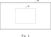
- FIG. FIG. 5 is a diagram for explaining the difference between the photographing range of the visible light camera and the photographing range of the far-infrared camera in the warning device according to the first embodiment
- FIG. 4 is a diagram for explaining warning display in the warning device according to the first embodiment
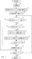
- FIG. 4A and 4B are diagrams for explaining the operation of the warning device according to the first embodiment
- FIG. FIG. 7 is a diagram illustrating another mode of operation of the warning device according to the first embodiment
- FIG. 10 is a block diagram of a warning device according to a second embodiment
- FIG. It is a figure explaining operation
- each configuration of the functional blocks described below is configured by hardware or software, or both, and may be configured from one piece of hardware or software, or may be configured from multiple pieces of hardware or software. good.
- Each function (each process) may be realized by an arithmetic unit (for example, a computer) having a CPU, a memory, and the like.
- a storage device may store a program for performing the creation method in the embodiment, and each function may be realized by executing the program stored in the storage device with a CPU.
- Non-transitory computer readable media include various types of tangible storage media. Examples of non-transitory computer-readable media include magnetic recording media (e.g. hard disk drives), CD-ROMs (Read Only Memory), CD-Rs, CD-R/Ws, semiconductor memories (e.g. mask ROMs, PROMs (Programmable ROM), EPROM (Erasable PROM), Flash ROM, RAM (random access memory)).
- the program may also be delivered to the computer on various types of transitory computer readable medium. Examples of transitory computer-readable media include electrical signals, optical signals, and electromagnetic waves. Transitory computer-readable media can deliver the program to the computer via wired channels, such as wires and optical fibers, or wireless channels.
- Embodiment 1 In the warning device 1 according to the first embodiment, when a pedestrian or the like is detected from the image taken by the far-infrared camera, the image taken by the far-infrared camera and the frame line indicating the detected pedestrian or the like are displayed on the display screen. and the like to warn the driver of the vehicle.
- FIG. 1 shows a block diagram of the warning device 1 according to the first embodiment.
- the warning device 1 according to the first embodiment has a warning control device 10, a far-infrared camera 11, a visible light camera 12, a recognition dictionary storage section 13, and a display section .
- the alarm control device 10 is realized by, for example, an arithmetic device such as a microcontroller unit (MCU) or a CPU capable of executing a program.
- the microcontroller unit may include a plurality of calculation units, and the plurality of calculation units may perform various processes in the program in parallel. Details of the processing blocks implemented within the alarm control device 10 will be described later.
- the far-infrared camera 11 is a camera for photographing the front of the vehicle, that is, the main traveling direction of the vehicle. , a so-called thermal image.
- the visible light camera 12 is a camera that photographs in the same direction as the far infrared camera 11, and outputs an image of the photographing range photographed with visible light. Matching of the photographing directions of the far-infrared camera 11 and the visible light camera 12 means that both cameras photograph the front of the vehicle.
- the imaging angle of view of the far-infrared camera 11 is often narrower than the imaging angle of view of the visible light camera 12, in such a case, the far-infrared camera 11 is located within the range of the imaging angle of view of the visible light camera 12. Includes the range of shooting angles.
- the recognition dictionary storage unit 13 stores a recognition dictionary obtained by machine-learning features such as the shape of an object to be detected by the detection unit 23, which will be described later.
- the recognition dictionary storage unit 13 is configured by, for example, a non-volatile storage device such as a flash memory.
- the display unit 14 displays an image captured by at least one of the far-infrared camera 11 and the visible light camera 12 to the driver of the vehicle.
- the display unit 14 may be, for example, a display installed on the dashboard of the vehicle.
- the alarm control device 10 has a first video acquisition unit 21 , a second video acquisition unit 22 , a detection unit 23 , a range identification unit 24 and a display control unit 25 .
- the processing blocks in the alarm control device 10 are processing blocks realized by programs or processing blocks implemented as dedicated hardware.
- the first image acquisition unit 21, the second image acquisition unit 22, the detection unit 23, the range identification unit 24, and the display control unit 25 can mutually link information by processing in the alarm control device 10 or by a bus. configured as
- the first image acquisition unit 21 acquires the first image captured by the far-infrared camera 11 that captures the traveling direction of the vehicle.
- the second image acquisition unit 22 acquires the second image captured by the visible light camera 12 .
- the detection unit 23 detects an object to warn the driver of the vehicle from the first image acquired by the first image acquisition unit.
- Objects to be warned to the driver of the vehicle are, for example, persons such as pedestrians, bicycles ridden by persons, animals, and other objects that are detected by differences in temperature distribution from the ambient temperature.
- the object to be warned to the driver of the vehicle may be an object that exists in front of the vehicle in the traveling direction and that exists in a position that requires attention while the vehicle is running, among the objects described above. good.
- the range specifying unit 24 specifies a first object range that is a range indicating the detected object in the first image, and also specifies a second object range corresponding to the first object range.
- a second object range in the image is identified.
- the first object range specified by the range specifying unit 24 is a range surrounding the object detected in the first image, and is indicated by, for example, a rectangular frame line.
- a rectangular frame line is a frame line that surrounds the entire outer shape of the detected object, and can indicate the position and size of the object on the display screen in addition to the presence of the object on the display screen.
- the first object range is indicated by a rectangular frame with an aspect ratio of 2:1 surrounding the detected person.
- the second object range specified by the range specifying unit 24 is a range indicating the same position in the second image as the first object range specified in the first image.
- a frame indicating the first object range It is indicated by a frame line having the same shape as the line.
- the first object range and the second object range are not limited to the forms described above, and various forms are possible.
- the display control unit 25 causes the display unit 14 to display the second image, in which the frame line or the like indicating the second object range is drawn, on the display unit 14 that can be viewed by the driver of the vehicle.
- the display control unit 25 preferably causes the display unit 14 to draw the second object range in the second image with reduced saturation or contrast. By lowering the saturation or contrast of the second image in this way, the frame line or the like indicating the range of the second object stands out against the display of the second image. can be verified.
- FIG. 2 shows a diagram for explaining the difference between the photographing range of the visible light camera and the photographing range of the far-infrared camera in the warning device 1 according to the first embodiment.
- the shooting ranges of the far-infrared camera 11 and the visible light camera 12 are the traveling direction of the vehicle, and shoot in the same direction.
- the far-infrared camera photographing range IR photographed by the far-infrared camera 11 is narrower than the visible light camera photographing range OP photographed by the visible light camera 12.
- FIG. In the example shown in FIG.
- the center of the visible light camera imaging range OP and the center of the far infrared camera imaging range IR are set to match.
- the visible light camera imaging range OP may be the imaging angle of view of the visible light camera 12
- the far infrared camera imaging range IR may be the imaging angle of view of the far infrared camera 11 .
- the coordinates of the visible light camera imaging range OP are associated with the coordinates of the far infrared camera imaging range IR in a range that matches the far infrared camera imaging range IR. Therefore, it is possible to specify the second object range in the second video based on the first object range specified in the first video.
- FIG. 3 shows a diagram for explaining warning display in the warning device 1 according to the first embodiment.
- the warning device 1 according to the first embodiment specifies a first object range OBJ_R1 when an object OBJ to be detected is detected in the far-infrared camera imaging range IR, and the visible light camera imaging range Identify a second object range OBJ_R2 at a position corresponding to the first object range OBJ_R1 in the OP. Then, the presence of the object OBJ is warned to the driver of the vehicle by clearly displaying the second object range OBJ_R2 in the second image, which is the image of the visible light camera imaging range OP.
- FIG. 4 shows a diagram for explaining the operation of the warning device 1 according to the first embodiment.
- the far-infrared camera 11 and the visible light camera 12 start photographing (step S1).
- the operation of step S1 is started when, for example, the engine of the vehicle in which the warning device 1 is mounted is turned on.
- object detection by the far-infrared camera 11 is performed when the illuminance around the vehicle is low, such as at night or in a tunnel
- the object detection is started when the illuminance becomes low enough to indicate nighttime or the inside of the tunnel.
- the warning device 1 After or simultaneously with the start of step S1, the warning device 1 causes the detector 23 to detect the object OBJ within the far-infrared camera shooting range IR from the first image acquired by the far-infrared camera 11 and the first image acquisition unit 21. is started (step S2). In addition, the warning device 1 starts displaying the second image (for example, the image of the visible light camera imaging range OP) acquired by the visible light camera 12 and the second image acquisition unit 22 by the display control unit 25 on the display unit 14. (step S3). The second image displayed on the display unit 14 may display a portion corresponding to the far-infrared camera imaging range IR from the visible light camera imaging range OP.
- the second image for example, the image of the visible light camera imaging range OP
- the range specifying unit 24 determines the position of the second object range OBJ_R2 corresponding to the first object range OBJ_R1. Identify (step S5). Then, the warning device 1 causes the display control unit 25 to display the second image showing the second object range OBJ_R2 on the display unit 14 (step S6). The second image showing the second object range OBJ_R2 is continued until the warning termination condition is satisfied, such as when the object OBJ disappears from the far-infrared camera imaging range IR, and the warning-required state is resolved (step S7). . Then, after the warning end condition is satisfied, the display control unit 25 displays the second image that does not include the second object range OBJ_R2 on the display unit 14 (step S8).
- the warning device 1 repeats the processing of steps S4 to S8 until the operation such as the engine is stopped. Note that, if the object OBJ is not detected in the far-infrared camera imaging range IR in step S4, the warning device 1 according to the first embodiment performs steps S5 to S8 until the object OBJ is detected in the far-infrared camera imaging range IR. is not executed, and the object OBJ detection process is continued (NO in step S4, NO in step S9).
- FIG. 5 shows a diagram for explaining another mode of operation of the warning device 1 according to the first embodiment.
- FIG. 5 shows a diagram for explaining another mode of operation of the warning device 1 according to the first embodiment.
- the first image is displayed on the display unit 14 in the non-detection state of the object OBJ.
- it is possible to select whether to display the first image or the second image on the display unit 14 during the period in which the object OBJ is not detected, depending on the specifications. can.
- the second object range indicating the existence position of the object OBJ is displayed in the second image.
- OBJ_R2 By displaying OBJ_R2 in an overlapping manner, a warning that should be given to the driver is presented to the driver in an easy-to-understand manner. Even if the driver of the vehicle cannot visually confirm the object to be warned outside the vehicle, the second object range OBJ_R2 is drawn in the second image similar to the scenery outside the vehicle, so that the driver can issue an appropriate warning. It is possible to grasp the position of the target object. In addition, by allowing the driver to appropriately grasp the position of the object to be warned, the time and frequency of viewing the display image can be reduced, and the driver's attention can be more focused on viewing the direction of travel.
- Embodiment 2 In a second embodiment, a warning device 2 that is another form of the warning device 1 according to the first embodiment will be described.
- the same reference numerals as those of the first embodiment are given to the constituent elements that are the same as those of the first embodiment, and the description thereof is omitted.
- FIG. 6 shows a block diagram of the warning device 2 according to the second embodiment.
- the warning device 2 according to the second embodiment is obtained by adding a vehicle interior photographing camera 15 to the warning device 1 according to the first embodiment, and replacing the alarm control device 10 with an alarm control device 30.
- the alarm control device 30 is obtained by adding a third image acquisition section 26 and a line-of-sight detection section 27 to the alarm control device 10 .
- the vehicle interior photographing camera 15 photographs the driver in the vehicle interior.
- the vehicle interior photographing camera 15 is installed so as to photograph the driver so that the driver's line of sight toward the display unit 14 can be seen.
- the third image acquisition unit 26 acquires the image captured by the vehicle interior camera 15 and transmits the image to the line-of-sight detection unit 27 .
- the line-of-sight detection unit 27 detects the line-of-sight direction of the driver of the vehicle.
- the display control unit 25 causes the display unit to display the first image in which the first object range is drawn.
- a second image in which the second object range is drawn is displayed.
- the predetermined time is, for example, 3 seconds.
- the case of looking back means, for example, within 3 seconds after the driver of the vehicle looks at the front of the vehicle after looking at the display unit 14 displaying the first image in which the first object range is drawn. For example, when the user looks at the display unit 14 displaying the first image in which the first object range is drawn again.
- the first image displayed on the display unit 14 Even though the first object range indicating the object to be warned is displayed, the object to be warned cannot be visually confirmed outside the vehicle. The same is true when the driver of the vehicle looks back at the display unit 14 displaying the first image in which the first object range is drawn.
- FIG. 7 shows a diagram for explaining the operation of the warning device 2 according to the second embodiment.
- FIG. 7 explains the operation of the warning device 2 when displaying the second image in which the second object range is drawn only when the driver looks back at the display unit 14 .
- the operation of the warning device 2 according to the second embodiment is obtained by adding the operation of step S21 to the operation of the warning device 1 according to the first embodiment shown in FIG. Step S21 is performed after the detection unit 23 detects the object OBJ in step S4.
- the first image captured by the far-infrared camera 11 is displayed on the display unit 14 when the object OBJ is not detected. can be recognized, the display of the first image is continued without displaying the second image including the second object range OBJ_R2 (the processing of steps S5 to S7 is performed) (step S21).
- the warning device 2 draws the second object range when it is determined that the driver needs to confirm the object OBJ using the second image.
- a second image can be displayed.
- Reference Signs List 1 2 warning device 10, 30 alarm control device 11 far-infrared camera 12 visible light camera 13 recognition dictionary storage unit 14 display unit 15 vehicle interior photography camera 21 first image acquisition unit 22 second image acquisition unit 23 detection unit 24 range specification Unit 25 Display control unit 26 Third image acquisition unit 27 Line of sight detection unit OP Visible light camera imaging range IR Far infrared camera imaging range OBJ Object OBJ_R1 First object range OBJ_R2 Second object range
Landscapes
- Engineering & Computer Science (AREA)
- General Physics & Mathematics (AREA)
- Physics & Mathematics (AREA)
- Multimedia (AREA)
- Theoretical Computer Science (AREA)
- Mechanical Engineering (AREA)
- Chemical & Material Sciences (AREA)
- Combustion & Propulsion (AREA)
- Transportation (AREA)
- Signal Processing (AREA)
- Computer Vision & Pattern Recognition (AREA)
- Human Computer Interaction (AREA)
- Health & Medical Sciences (AREA)
- General Health & Medical Sciences (AREA)
- Ophthalmology & Optometry (AREA)
- Traffic Control Systems (AREA)
- Image Analysis (AREA)
- Closed-Circuit Television Systems (AREA)
- Studio Devices (AREA)
Priority Applications (3)
| Application Number | Priority Date | Filing Date | Title |
|---|---|---|---|
| EP21931713.8A EP4310814A4 (en) | 2021-03-19 | 2021-12-01 | Warning device and warning method |
| CN202180088960.6A CN116762097A (zh) | 2021-03-19 | 2021-12-01 | 警告装置和警告方法 |
| US18/235,491 US20230391192A1 (en) | 2021-03-19 | 2023-08-18 | Warning apparatus and warning method |
Applications Claiming Priority (2)
| Application Number | Priority Date | Filing Date | Title |
|---|---|---|---|
| JP2021045681A JP7585909B2 (ja) | 2021-03-19 | 2021-03-19 | 警告装置及び警告方法 |
| JP2021-045681 | 2021-03-19 |
Related Child Applications (1)
| Application Number | Title | Priority Date | Filing Date |
|---|---|---|---|
| US18/235,491 Continuation US20230391192A1 (en) | 2021-03-19 | 2023-08-18 | Warning apparatus and warning method |
Publications (1)
| Publication Number | Publication Date |
|---|---|
| WO2022195970A1 true WO2022195970A1 (ja) | 2022-09-22 |
Family
ID=83320099
Family Applications (1)
| Application Number | Title | Priority Date | Filing Date |
|---|---|---|---|
| PCT/JP2021/044063 Ceased WO2022195970A1 (ja) | 2021-03-19 | 2021-12-01 | 警告装置及び警告方法 |
Country Status (5)
| Country | Link |
|---|---|
| US (1) | US20230391192A1 (enExample) |
| EP (1) | EP4310814A4 (enExample) |
| JP (1) | JP7585909B2 (enExample) |
| CN (1) | CN116762097A (enExample) |
| WO (1) | WO2022195970A1 (enExample) |
Cited By (1)
| Publication number | Priority date | Publication date | Assignee | Title |
|---|---|---|---|---|
| WO2025052343A1 (en) * | 2023-09-08 | 2025-03-13 | Gentex Corporation | Imaging and display system for modifying color video stream by detecting objects in ir video stream |
Citations (7)
| Publication number | Priority date | Publication date | Assignee | Title |
|---|---|---|---|---|
| JPH10206787A (ja) * | 1997-01-20 | 1998-08-07 | Honda Motor Co Ltd | 車両用ヘッドマウントディスプレイ装置 |
| WO2012073722A1 (ja) * | 2010-12-01 | 2012-06-07 | コニカミノルタホールディングス株式会社 | 画像合成装置 |
| JP2012131491A (ja) * | 2006-11-10 | 2012-07-12 | Autoliv Development Ab | 物体検知システム |
| JP2014197727A (ja) * | 2013-03-29 | 2014-10-16 | マツダ株式会社 | 車両用撮像装置 |
| JP2020027380A (ja) | 2018-08-10 | 2020-02-20 | 株式会社Jvcケンウッド | 認識処理装置、認識処理方法及び認識処理プログラム |
| JP2020043400A (ja) * | 2018-09-06 | 2020-03-19 | アイシン精機株式会社 | 周辺監視装置 |
| JP2021045681A (ja) | 2020-12-28 | 2021-03-25 | 株式会社三洋物産 | 遊技機 |
Family Cites Families (3)
| Publication number | Priority date | Publication date | Assignee | Title |
|---|---|---|---|---|
| CN106028913B (zh) * | 2014-02-19 | 2018-03-30 | 三菱电机株式会社 | 显示控制装置、显示控制装置的显示控制方法 |
| KR102118066B1 (ko) * | 2014-08-20 | 2020-06-03 | 현대모비스 주식회사 | 주행 안전을 위한 차량 제어방법 |
| JP2018148530A (ja) * | 2017-03-09 | 2018-09-20 | 株式会社Jvcケンウッド | 車両用表示制御装置、車両用表示システム、車両用表示制御方法およびプログラム |
-
2021
- 2021-03-19 JP JP2021045681A patent/JP7585909B2/ja active Active
- 2021-12-01 EP EP21931713.8A patent/EP4310814A4/en active Pending
- 2021-12-01 CN CN202180088960.6A patent/CN116762097A/zh active Pending
- 2021-12-01 WO PCT/JP2021/044063 patent/WO2022195970A1/ja not_active Ceased
-
2023
- 2023-08-18 US US18/235,491 patent/US20230391192A1/en active Pending
Patent Citations (7)
| Publication number | Priority date | Publication date | Assignee | Title |
|---|---|---|---|---|
| JPH10206787A (ja) * | 1997-01-20 | 1998-08-07 | Honda Motor Co Ltd | 車両用ヘッドマウントディスプレイ装置 |
| JP2012131491A (ja) * | 2006-11-10 | 2012-07-12 | Autoliv Development Ab | 物体検知システム |
| WO2012073722A1 (ja) * | 2010-12-01 | 2012-06-07 | コニカミノルタホールディングス株式会社 | 画像合成装置 |
| JP2014197727A (ja) * | 2013-03-29 | 2014-10-16 | マツダ株式会社 | 車両用撮像装置 |
| JP2020027380A (ja) | 2018-08-10 | 2020-02-20 | 株式会社Jvcケンウッド | 認識処理装置、認識処理方法及び認識処理プログラム |
| JP2020043400A (ja) * | 2018-09-06 | 2020-03-19 | アイシン精機株式会社 | 周辺監視装置 |
| JP2021045681A (ja) | 2020-12-28 | 2021-03-25 | 株式会社三洋物産 | 遊技機 |
Non-Patent Citations (1)
| Title |
|---|
| See also references of EP4310814A4 |
Cited By (1)
| Publication number | Priority date | Publication date | Assignee | Title |
|---|---|---|---|---|
| WO2025052343A1 (en) * | 2023-09-08 | 2025-03-13 | Gentex Corporation | Imaging and display system for modifying color video stream by detecting objects in ir video stream |
Also Published As
| Publication number | Publication date |
|---|---|
| EP4310814A4 (en) | 2024-06-19 |
| US20230391192A1 (en) | 2023-12-07 |
| JP7585909B2 (ja) | 2024-11-19 |
| CN116762097A (zh) | 2023-09-15 |
| EP4310814A1 (en) | 2024-01-24 |
| JP2022144606A (ja) | 2022-10-03 |
Similar Documents
| Publication | Publication Date | Title |
|---|---|---|
| CN107336669B (zh) | 车辆安全防护系统及其方法 | |
| US7362215B2 (en) | System and method for monitoring the surroundings of a vehicle | |
| US9098928B2 (en) | Image-processing system and image-processing method | |
| JP6137081B2 (ja) | 車載機器 | |
| JP5277974B2 (ja) | 運転支援装置 | |
| JP5093611B2 (ja) | 車両周辺確認装置 | |
| US11465629B2 (en) | Recognition processing apparatus, recognition processing method, and recognition processing program | |
| US11708032B2 (en) | Driving support device | |
| KR101729486B1 (ko) | Avm 시스템에서의 사각 지대 감시 방법 및 그 avm 시스템 | |
| WO2020006792A1 (zh) | 一种图像处理方法、机构及后视镜 | |
| WO2018047393A1 (ja) | 映像出力システム | |
| JP2022144606A (ja) | 警告装置及び警告方法 | |
| JP2018148530A (ja) | 車両用表示制御装置、車両用表示システム、車両用表示制御方法およびプログラム | |
| JP2005182305A (ja) | 車両走行支援装置 | |
| KR102010407B1 (ko) | 스마트 리어뷰 시스템 | |
| JP6690312B2 (ja) | 車両用表示制御装置、車両用表示システム、車両用表示制御方法およびプログラム | |
| JP5617678B2 (ja) | 車両用表示装置 | |
| JP2010056975A (ja) | リアカメラによる物体検知方式 | |
| CN112470465B (zh) | 俯瞰图像生成装置以及计算机可读存储介质 | |
| JP2007139564A (ja) | 障害物検出システム、障害物検出方法及びコンピュータプログラム | |
| JP2018107574A (ja) | 車両用視認装置 | |
| JP2009104442A (ja) | 駐車場管理システム | |
| JP2020057981A (ja) | 画像作成システム、画像作成装置、及び画像作成装置の制御方法 | |
| KR101750161B1 (ko) | 관심영역 이미지 패치 관리 시스템 및 방법 | |
| JP2008244906A (ja) | 車両用表示装置 |
Legal Events
| Date | Code | Title | Description |
|---|---|---|---|
| 121 | Ep: the epo has been informed by wipo that ep was designated in this application |
Ref document number: 21931713 Country of ref document: EP Kind code of ref document: A1 |
|
| WWE | Wipo information: entry into national phase |
Ref document number: 202180088960.6 Country of ref document: CN |
|
| WWE | Wipo information: entry into national phase |
Ref document number: 2021931713 Country of ref document: EP |
|
| NENP | Non-entry into the national phase |
Ref country code: DE |
|
| ENP | Entry into the national phase |
Ref document number: 2021931713 Country of ref document: EP Effective date: 20231019 |