WO2022195804A1 - 電動機 - Google Patents
電動機 Download PDFInfo
- Publication number
- WO2022195804A1 WO2022195804A1 PCT/JP2021/011095 JP2021011095W WO2022195804A1 WO 2022195804 A1 WO2022195804 A1 WO 2022195804A1 JP 2021011095 W JP2021011095 W JP 2021011095W WO 2022195804 A1 WO2022195804 A1 WO 2022195804A1
- Authority
- WO
- WIPO (PCT)
- Prior art keywords
- magnetic flux
- electric motor
- stator
- motor according
- stator core
- Prior art date
- Legal status (The legal status is an assumption and is not a legal conclusion. Google has not performed a legal analysis and makes no representation as to the accuracy of the status listed.)
- Ceased
Links
Images




Classifications
-
- H—ELECTRICITY
- H02—GENERATION; CONVERSION OR DISTRIBUTION OF ELECTRIC POWER
- H02K—DYNAMO-ELECTRIC MACHINES
- H02K1/00—Details of the magnetic circuit
- H02K1/06—Details of the magnetic circuit characterised by the shape, form or construction
- H02K1/12—Stationary parts of the magnetic circuit
- H02K1/14—Stator cores with salient poles
- H02K1/146—Stator cores with salient poles consisting of a generally annular yoke with salient poles
- H02K1/148—Sectional cores
-
- H—ELECTRICITY
- H02—GENERATION; CONVERSION OR DISTRIBUTION OF ELECTRIC POWER
- H02K—DYNAMO-ELECTRIC MACHINES
- H02K1/00—Details of the magnetic circuit
- H02K1/06—Details of the magnetic circuit characterised by the shape, form or construction
- H02K1/12—Stationary parts of the magnetic circuit
-
- H—ELECTRICITY
- H02—GENERATION; CONVERSION OR DISTRIBUTION OF ELECTRIC POWER
- H02K—DYNAMO-ELECTRIC MACHINES
- H02K5/00—Casings; Enclosures; Supports
- H02K5/04—Casings or enclosures characterised by the shape, form or construction thereof
- H02K5/08—Insulating casings
Definitions
- This disclosure relates to electric motors.
- a motor is known in which the axial length of the stator and the axial length of the permanent magnets of the rotor are approximately the same. See, for example, US Pat.
- An object of the present disclosure is to facilitate positioning of the magnetic flux capturing member.
- An electric motor includes a rotor main body supported by a rotating shaft and a stator, and the stator includes a first end face that is one end face in the axial direction of the rotating shaft.
- a stator core having a second end face that is the other end face, and a stator core that is arranged on the core end face that is at least one end face of the first end face and the second end face, and takes in the magnetic flux of the rotor body.
- a magnetic flux take-in member made of a magnetic material, the magnetic flux take-in member comprising at least a bent portion projecting in a direction away from the rotor body and a curved portion having a concave surface facing inward in the radial direction of the stator. have one.
- positioning of the magnetic flux capturing member can be facilitated.
- FIG. 1 is a cross-sectional view schematically showing the configuration of an electric motor according to Embodiment 1;
- FIG. FIG. 2 is a perspective view showing part of the configuration of a stator core of the stator shown in FIG. 1;
- FIG. 3 is a plan view showing part of the configuration of the stator core shown in FIGS. 1 and 2;
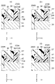
- FIG. (a) is an enlarged cross-sectional view schematically showing the structure of B1 part of FIG. (b) to (d) are enlarged cross-sectional views schematically showing other examples of the structure of the B1 portion of FIG. 3A is an enlarged cross-sectional view schematically showing a part of the configuration of the stator of the electric motor according to Modification 1 of Embodiment 1;
- FIG. 7(b) to 7(d) are enlarged cross-sectional views schematically showing other examples of part of the configuration of the stator of the electric motor according to Modification 1 of Embodiment 1.
- FIG. 8A is an enlarged cross-sectional view schematically showing a part of the configuration of the stator of the electric motor according to Modification 2 of Embodiment 1;
- FIG. 7(b) to (d) are enlarged cross-sectional views schematically showing other examples of part of the configuration of the stator of the electric motor according to Modification 2 of Embodiment 1.
- FIG. 8A is an enlarged cross-sectional view schematically showing a part of the configuration of the stator of the electric motor according to Modification 1 of Embodiment 2
- FIG. 9(b) to 9(d) are enlarged cross-sectional views schematically showing other examples of part of the configuration of the stator of the electric motor according to Modification 1 of Embodiment 2.
- FIG. 8A is an enlarged cross-sectional view schematically showing a part of the configuration of the stator of the electric motor according to Modification 2 of Embodiment 2;
- FIG. 9(b) to 9(d) are enlarged cross-sectional views schematically showing other examples of part of the configuration of the stator of the electric motor according to Modification 2 of Embodiment 2.
- FIG. FIG. 11 is a perspective view showing the configuration of a stator of an electric motor according to Embodiment 3;
- FIG. 12 is an enlarged perspective view showing part of the configuration of the stator shown in FIG. 11;
- 13(a) is an enlarged plan view showing a part of the configuration of the stator shown in FIGS. 11 and 12;
- FIG. 13(b) is a cross-sectional view of part of the structure of the stator shown in FIG. 13(a) taken along line A13-A13.
- FIG. 13 is a perspective view showing the configuration of the stator core and insulator shown in FIGS. 11 and 12;
- FIG. 15 is an enlarged perspective view showing a part of the configuration of the stator core and insulator shown in FIG. 14;
- FIG. 13(a) is a plan view schematically showing the configuration of the magnetic flux take-in member shown in FIG. 13(a);
- FIG. (b) to (d) are plan views schematically showing other examples of the configuration of the magnetic flux taking-in member according to the third embodiment.
- 12A is a plan view schematically showing a configuration of a magnetic flux taking-in member according to Modification 1 of Embodiment 3;
- FIG. 12B is a plan view schematically showing another example of the configuration of the magnetic flux take-in member according to Modification 1 of Embodiment 3;
- FIG. 11 is a plan view schematically showing the configuration of a magnetic flux take-in member according to Modification 2 of Embodiment 3;
- the z-axis is the coordinate axis parallel to the rotor axis of the motor.
- the x-axis is a coordinate axis orthogonal to the z-axis.
- the y-axis is a coordinate axis orthogonal to both the x-axis and the z-axis.
- FIG. 1 is a cross-sectional view showing the configuration of electric motor 100 according to Embodiment 1.
- the electric motor 100 has a rotor 1 , bearings 2 and 3 and a stator 5 .
- the rotor 1 has a shaft 11 as a rotating shaft and permanent magnets 12 as a rotor main body.
- the rotor 1 is rotatable around the axis A of the shaft 11 .
- the shaft 11 protrudes from the stator 5 to the +z-axis side.
- the direction along the circumference of the circle centered on the axis A of the shaft 11 is called “circumferential direction C”.
- the z-axis direction is also called “axial direction”
- the direction perpendicular to the axial direction is called “radial direction”.
- the projecting side of the shaft 11 that is, the +z-axis side
- the side opposite to the load side of the shaft 11 that is, the -z-axis side
- anti-load side the projecting side of the shaft 11
- the permanent magnet 12 is attached to the shaft 11.
- the permanent magnet 12 is a cylindrical magnet elongated in the z-axis direction.
- N poles and S poles are alternately formed on the outer peripheral surface of the permanent magnet 12 .
- the rotor main body of the rotor 1 may be composed of a rotor core fixed to the shaft 11 and permanent magnets attached to the rotor core.
- a bearing 2 is a bearing that supports the load side of the shaft 11
- a bearing 3 is a bearing that supports the non-load side of the shaft 11 .
- the stator 5 has a stator core 20 and windings 30 wound around the stator core 20 .
- the stator core 20 has a first end face (specifically, the +z-axis side end face) 20a that is one end face in the axial direction, and a second end face (specifically, the -z shaft-side end face) 20b.
- the permanent magnet 12 described above has a third end face (specifically, the +z-axis side end face) 12a that is one end face in the axial direction, and a fourth end face (specifically, the other end face) 12a that is the other end face. , -z-axis side end face) 12b.
- L 1 is the first length (hereinafter also referred to as “axial length”) that is the length of the stator core 20 in the z-axis direction, and the second length that is the length of the permanent magnet 12 in the z-axis direction is Length L 1 is shorter than length L 2 when L 2 is used. That is, the length L1 and the length L2 satisfy the following formula ( 1 ).
- the stator core 20 has a plurality of electromagnetic steel sheets (not shown) laminated in the z-axis direction. Since the length L1 is shorter than the length L2, the number of magnetic steel sheets provided in the stator core 20 is reduced, so the cost of the stator core 20 can be reduced. Therefore, the cost of electric motor 100 can be reduced.
- the +z-axis side end face 20a and the ⁇ z-axis side end face 20b of the stator core 20 are arranged between the +z-axis side end face 12a and the ⁇ z-axis side end face 12b of the permanent magnet 12. It is One of the +z-axis side end surface 20a and the ⁇ z-axis side end surface 20b of the electric motor 100 is located between the +z-axis side end surface 12a and the ⁇ z-axis side end surface 12b of the permanent magnet 12. It can be realized even if it is not arranged.
- the ⁇ z-axis side end surface 20b of the stator core 20 may be located axially outside the ⁇ z-axis side end surface 12b of the permanent magnet 12 .
- the end faces 20a and 20b of the stator core 20 in the z-axis direction are also called “core end faces”.
- FIG. 2 is a perspective view showing part of the configuration of the stator core 20 shown in FIG.
- FIG. 3 is a plan view showing part of the configuration of the stator core 20 shown in FIGS. 1 and 2.
- the stator core 20 has a yoke 21 extending in the circumferential direction C and multiple teeth 22 .
- a plurality of teeth 22 are arranged in the circumferential direction C at predetermined intervals.
- the plurality of teeth 22 are radially opposed to the rotor 1 (see FIG. 1).
- Each tooth 22 of the plurality of teeth 22 has a tooth body portion 22a and a tooth tip portion 22b.
- the tooth main body portion 22 a extends radially inward from the yoke 21 .
- the tooth tip portion 22b is arranged radially inward of the tooth body portion 22a and is wider in the circumferential direction C than the tooth body portion 22a.
- the axial length of the stator core 20 in the z-axis direction is shorter than the axial length of the permanent magnets 12 in the z-axis direction, as shown in FIG. It is conceivable that the magnetic flux generated at the end in the z-axis direction (hereinafter referred to as “overhang portion 12 c ”) that does not face the stator core 20 and the windings 30 becomes difficult.
- overhang portion 12 c the magnetic flux generated at the end in the z-axis direction
- the efficiency of the electric motor 100 may decrease.
- the stator 5 has magnetic flux take-in members 40 arranged on the end faces 20a and 20b of the stator core 20 in the z-axis direction.
- the magnetic flux take-in member 40 is made of a magnetic material that takes in the magnetic flux of the permanent magnet 12 .
- the magnetic flux generated at the overhang portion 12c of the permanent magnet 12 can easily flow to the stator core 20 and the windings 30 via the magnetic flux intake member 40. As shown in FIG. Therefore, it is possible to prevent the efficiency of the electric motor 100 from being lowered.
- Embodiment 1 for example, even when a magnet with a low magnetic force (for example, a ferrite magnet) is used as the permanent magnet 12, a decrease in the efficiency of the electric motor 100 is suppressed, and the Cost can be reduced.
- a magnet with a low magnetic force for example, a ferrite magnet
- the magnetic flux take-in member 40 is, for example, a metal piece made of metal. Specifically, the magnetic flux taking-in member 40 is an iron piece made of iron.
- the magnetic flux taking-in members 40 are arranged on the end faces 20a and 20b of the stator core 20 on both sides in the z-axis direction. As a result, the magnetic flux generated by the overhang portions 12c on both sides of the permanent magnet 12 in the z-axis direction can be taken in, so that the efficiency of the electric motor 100 can be further prevented from being lowered.
- the stator 5 may have a magnetic flux taking-in member disposed on one of the +z-axis side end surface 20a and the ⁇ z-axis side end surface 20b of the stator core 20 . In this case, since the number of parts in electric motor 100 is reduced, the manufacturing process of electric motor 100 can be simplified. In other words, the magnetic flux take-in member 40 may be arranged on at least one of the +z-axis side end surface 20a and the ⁇ z-axis side end surface 20b of the stator core 20. FIG.
- the magnetic flux take-in member 40 is arranged at the tooth tip 22b of the tooth 22. As shown in FIG. As a result, the magnetic flux capturing member 40 is arranged close to the permanent magnet 12 , so that the magnetic flux of the permanent magnet 12 is easily captured by the magnetic flux capturing member 40 .
- the shape of the magnetic flux taking-in member 40 when viewed in the z-axis direction is, for example, a rectangular shape.
- the shape of the magnetic flux capturing member 340 when viewed in the z-axis direction is a curved shape (for example, an arc shape) having a radially inward concave surface 341a. ).
- FIG. 4(a) is an enlarged sectional view schematically showing the structure of the B1 part shown in FIG.
- the magnetic flux capturing member 40 has a bent portion 41 that protrudes away from the permanent magnet 12 (specifically, radially outward). This facilitates positioning of magnetic flux capturing member 40 when fixing magnetic flux capturing member 40 to a fixing member (insulator 50 in the first embodiment) described later.
- the bent portion 41 is provided at the end on the stator core 20 side among the ends of the magnetic flux taking-in member 40 in the z-axis direction.
- the contact area between the magnetic flux capturing member 40 and the end surface 20a of the stator core 20 in the z-axis direction is increased, so that the fixing strength of the magnetic flux capturing member 40 can be improved.
- the magnetic flux density of the magnetic flux may increase as it approaches the stator core.
- the contact area between the magnetic flux capturing member 40 and the end face 20a of the stator core 20 in the z-axis direction increases, the magnetic flux flows to the stator core 20 via the magnetic flux capturing member 40. An increase in the magnetic flux density of the magnetic flux can be mitigated.
- the bent portion 41 is a portion of the magnetic flux take-in member 40 in which the end portion on the stator core 20 side is bent radially outward at right angles.
- the bent portion 41 may be provided at the end portion opposite to the stator core 20 .
- the bent portion 41 may have a shape that is inclined radially outward as it moves away from the end surface 20a of the stator core 20 in the z-axis direction.
- the stator 5 further has an insulator 50 as an insulating member for insulating the windings 30 and the stator core 20 from each other.
- the insulator 50 is made of thermoplastic resin such as PPS (Poly Phenylene Sulfide) and PBT (Poly Butylene Terephthalate).
- the insulator 50 includes a first wall portion 71 provided radially outside the winding 30 to cover the yoke 21, and a first wall portion 71 radially inside the winding 30. and a second wall portion 72 that is provided at the end and covers the teeth 22 (for example, the tooth tip portions 22b).
- the insulator 50 is a fixing member that fixes the magnetic flux capturing member 40 by coming into contact with the radially outer surface 43 of the magnetic flux capturing member 40. It also has a function as Thereby, the stator 5 does not need to have another member for fixing the magnetic flux taking-in member 40 . Therefore, the number of parts in electric motor 100 can be reduced.
- the insulator 50 is in contact with the entire radially outer surface 43 of the magnetic flux take-in member 40 .
- the insulator 50 is in contact with the surface of the magnetic flux take-in member 40 opposite to the permanent magnet 12 (see FIG. 1). This prevents the insulator 50 from interfering with the flow of the magnetic flux of the permanent magnet 12 .
- the insulator 50 does not extend beyond the radially outer surface 43 of the magnetic flux capturing member 40, as shown in FIG. may be in contact with a part of the That is, the insulator 50 only needs to be in contact with at least a portion of the radially outer surface 43 of the magnetic flux take-in member 40 .
- the second wall portion 72 of the insulator 50 has a radially inward surface 51 and an engaging portion 52 provided on the radially inward surface 51 .
- the engaging portion 52 is engaged with the bent portion 41 of the magnetic flux taking-in member 40 . This facilitates positioning of the magnetic flux capturing member 40 when fixing the magnetic flux capturing member 40 to the insulator 50 . Moreover, since the contact area between the magnetic flux capturing member 40 and the insulator 50 increases, the fixing strength of the magnetic flux capturing member 40 can be further improved.
- the engaging portion 52 is, for example, a stepped portion (hereinafter also referred to as a “recess”) provided by notching the end portion of the radially inward surface 51 on the stator core 20 side. ), and the bent portion 41 is fitted into the recessed portion.
- winding stress when the winding is wound around the tooth 22 via the insulator 50, stress (hereinafter also referred to as “winding stress") is generated due to the tension of the winding acting on the insulator 50.
- the height H of the coil end portion of the winding 30 decreases radially inward from the tip of the coil end portion.
- the winding stress generated in second wall portion 72 supporting magnetic flux taking-in member 40 is smaller than the winding stress generated in first wall portion 71 . Therefore, deformation of the radially inner portion of the insulator 50 due to winding stress can be prevented.
- the height H of the coil end portion decreases from the outside to the inside in the radial direction of the winding 30 .
- the height H is the height of the coils stacked on the z-axis direction end surfaces of the teeth 22 by winding the coils around the teeth 22 .
- the height H of the coil end portions of the windings 30 may be highest at the center in the radial direction of the windings 30 and may become lower toward the radially inner side or the radially outer side from the center.
- bent portion 41 does not necessarily have to have a structure in which the end portion of the magnetic flux taking-in member 40 on the stator core 20 side is bent.
- the magnetic flux capturing member 40 has a bent portion 41 formed by bending the end opposite to the stator core 20 (that is, the end on the +z-axis side).
- the insulator 50 has an engaging portion 53 provided at the +z-axis side end portion of the radially inward surface 51 .
- the engaging portion 53 is engaged with the bent portion 41 .
- the magnetic flux taking-in member 40 can be engaged with the insulator 50 after the insulator 50 is molded, so the productivity of the stator 5 can be improved.
- the fixing strength of the magnetic flux capturing member 40 can be improved.
- the magnetic flux take-in member 40 may have a plurality of bent portions 41 formed by bending both ends in the z-axis direction. As a result, the contact area between the magnetic flux capturing member 40 and the insulator 50 is further increased, so that the fixing strength of the magnetic flux capturing member 40 can be further improved.
- the bent portion 41 extends in a direction away from the permanent magnet 12 (see FIG. 1) (that is, in a radial outside).
- the +z-axis side end portion 54 of the radially inward surface 51 of the insulator 50 is an inclined surface that is radially outwardly inclined with increasing distance from the z-axis direction end surface 20 a of the stator core 20 .
- the height H of the coil end portion of the winding 30 increases from the inner side to the outer side in the radial direction. Since the shape of the bent portion 41 when viewed in the zx cross section is the above-described inclined shape, the distance between the winding 30 and the bent portion 41 can be made uniform. Therefore, the magnetic flux captured by the bent portion 41 of the magnetic flux capturing member 40 can easily flow through the winding 30 .
- the magnetic flux take-in member 40 may have a structure in which the structures shown in FIGS. 4(a) and 4(d) are combined.
- electric motor 100 has rotor 1 having permanent magnets 12 and stator 5 having stator core 20 .
- the length L1 of the stator core 20 in the z - axis direction is shorter than the length L2 of the permanent magnets 12 in the z-axis direction.
- the stator 5 includes the magnetic flux capturing members 40 which are arranged on the end faces 20a and 20b of the stator core 20 in the z-axis direction and which are made of a magnetic material and capture the magnetic flux of the permanent magnets 12. have.
- the magnetic flux generated at the overhang portion 12 c of the permanent magnet 12 flows through the stator core 20 and the windings 30 via the magnetic flux intake member 40 . Therefore, a decrease in the amount of magnetic flux flowing from the permanent magnets 12 to the stator 5 can be suppressed. Therefore, in the electric motor 100, it is possible to suppress a decrease in the amount of magnetic flux flowing from the permanent magnets 12 to the stator 5 while suppressing costs.
- the magnetic flux take-in member 40 has the bent portion 41 projecting in the direction away from the permanent magnet 12 . This facilitates positioning of the magnetic flux capturing member 40 when fixing the magnetic flux capturing member 40 to the insulator 50 .
- the bent portion 41 is a portion of the magnetic flux capturing member 40 in which the end portion of the magnetic flux capturing member 40 on the stator core 20 side is bent.
- the contact area between the magnetic flux capturing member 40 and the stator core 20 is increased, so that the fixing strength of the magnetic flux capturing member 40 can be improved.
- the increase in the magnetic flux density of the magnetic flux flowing through the stator core 20 via the magnetic flux taking-in member 40 can be mitigated.
- the stator 5 has the insulator 50 that insulates the windings 30 and the stator core 20, and the insulator 50 also functions as a fixing member that fixes the magnetic flux taking-in member 40. do. Thereby, the stator 5 does not need to have another member for fixing the magnetic flux taking-in member 40 . Therefore, the number of parts in electric motor 100 can be reduced.
- the insulator 50 has the engaging portion 52 that engages the bent portion 41 . This facilitates positioning of the magnetic flux taking-in member 40 . Moreover, since the contact area between the magnetic flux capturing member 40 and the insulator 50 increases, the fixing strength of the magnetic flux capturing member 40 can be improved.
- FIG. 5(a) is an enlarged sectional view schematically showing the configuration of the stator 5A of the electric motor according to Modification 1 of Embodiment 1.
- FIG. 5(a) the same reference numerals as those shown in FIG. 4(a) are attached to the constituent elements that are the same as or correspond to the constituent elements shown in FIG. 4(a).
- the electric motor according to Modification 1 of Embodiment 1 differs from electric motor 100 according to Embodiment 1 in the shape of insulator 50A of stator 5A. Except for this point, the electric motor according to Modification 1 of Embodiment 1 is the same as electric motor 100 according to Embodiment 1.
- FIG. 1 and 2 will therefore be referred to in the following description.
- the stator 5A of the electric motor has a stator core 20, windings 30, a magnetic flux take-in member 40, and an insulator 50A.
- the insulator 50A includes a first wall portion 71A provided radially outside the winding 30 (see FIG. 1) to cover the yoke 21 (see FIG. 2), and a first wall portion 71A provided radially inside the winding 30. 2nd wall part 72A which covers the teeth 22 (refer FIG. 2).
- insulator 50A is in contact with a portion of radially outer surface 43 of magnetic flux capturing member 40 (specifically, the end on the ⁇ z axis side).
- the length L 6 is the length Shorter than L5 .
- FIGS. 5(b) to 5(d) are enlarged cross-sectional views schematically showing another example of a part of the configuration of the stator 5A of the electric motor according to Modification 1 of Embodiment 1.
- FIG. The shape of the insulator 50A is not limited to the shape shown in FIG.
- the shape of the magnetic flux capturing member 40 shown in FIGS. 5(b) to (d) is the same as the shape of the magnetic flux capturing member 40 shown in FIGS. 4(b) to (d).
- the insulator 50A is in contact with the ⁇ z-axis side end portion of the radially outer surface 43 of the magnetic flux take-in member 40 as well.
- insulator 50A is in contact with a portion of radially outer surface 43 of magnetic flux take-in member 40 .
- the amount of thermoplastic resin that is the raw material of the insulator 50A is reduced, so the cost of the electric motor can be reduced.
- FIG. 6(a) is an enlarged sectional view schematically showing a part of the configuration of the stator 5B of the electric motor according to Modification 2 of Embodiment 1.
- FIG. 6(a) the same or corresponding components as those shown in FIG. 4(a) are given the same reference numerals as those shown in FIG. 4(a).
- the electric motor according to Modification 2 of Embodiment 1 differs from the electric motor according to Embodiment 1 in the shape of insulator 50B of stator 5B. Except for this point, the electric motor according to Modification 2 of Embodiment 1 is the same as electric motor 100 according to Embodiment 1.
- FIG. 1 and 2 will therefore be referred to in the following description.
- the stator 5B of the electric motor has a stator core 20, windings 30, a magnetic flux take-in member 40, and an insulator 50B.
- the insulator 50B includes a first wall portion 71B provided radially outside the winding 30 (see FIG. 1) to cover the yoke 21 (see FIG. 2), and a first wall portion 71B radially inside the winding 30. and a second wall portion 72B covering the teeth 22 (see FIG. 2).
- the second wall portion 72B of the insulator 50B is in contact with the entire radially outer surface 43 of the magnetic flux take-in member 40 . Further, the second wall portion 72B of the insulator 50B is in contact with the end portion 44 of the magnetic flux taking-in member 40 in the z-axis direction, which is on the side opposite to the stator core 20 . As a result, the contact area between the magnetic flux capturing member 40 and the insulator 50B is further increased, so that the fixing strength of the magnetic flux capturing member 40 can be further improved.
- FIGS. 6(b) to 6(d) are enlarged cross-sectional views schematically showing other examples of part of the configuration of the stator 5B of the electric motor according to Modification 2 of Embodiment 1.
- FIG. The shape of the insulator 50B is not limited to the shape shown in FIG.
- the shape of the magnetic flux receiving member 40 shown in FIGS. 6(b) to (d) is the same as the shape of the magnetic flux receiving member 40 shown in FIGS. 4(b) to (d).
- the insulator 50B is also in contact with the end 44 of the magnetic flux take-in member 40 in the z-axis direction opposite to the stator core 20.
- the second wall portion 72B of the insulator 50B is also in contact with the radially inner surface 45 of the bent portion 41.
- the bent portion 41 is covered with the insulator 50B.
- the insulator 50B is interposed between the bent portion 41 and the permanent magnet 12 (see FIG. 1) in the radial direction. Therefore, even if a magnetic attraction force is generated between the bent portion 41 and the permanent magnet 12 during rotation, the magnetic flux taking-in member 40 is more unlikely to come off from the stator core 20 .
- FIG. 7 is a cross-sectional view schematically showing the configuration of electric motor 200 according to the second embodiment. 7, the same or corresponding components as those shown in FIG. 1 are given the same reference numerals as those shown in FIG. Electric motor 200 according to Embodiment 2 is different from electric motor 100 according to Embodiment 1 in that the stator has molded resin portion 60 . Electric motor 200 according to the second embodiment is the same as electric motor 100 according to the first embodiment except for this point.
- the electric motor 200 has a rotor 1 having bearings 2 and 3, a metal bracket 4 as a bearing holding member, and a molded stator 205 as a stator.
- the metal bracket 4 holds the bearing 2 on the load side.
- the metal bracket 4 is made of, for example, a steel plate.
- the molded stator 205 has a stator core 20 , windings 30 , magnetic flux take-in members 40 , insulators 50 and molded resin portion 60 .
- the mold resin portion 60 is made of, for example, thermosetting resin.
- the mold resin portion 60 is molded by injection molding, for example. Also, the molded resin portion 60 is integrated with the stator core 20, the windings 30, the magnetic flux taking-in member 40, and the insulator 50 by integral molding.
- the mold resin portion 60 has an opening portion 61 and a bearing holding portion 62 .
- a metal bracket 4 is fixed to the opening 61 .
- the bearing holding portion 62 is a concave portion in which the bearing 3 on the anti-load side of the mold resin portion 60 is held.
- FIG. 8(a) is an enlarged sectional view schematically showing the structure of the B2 portion shown in FIG.
- the mold resin portion 60 is in contact with the end portion 44 of the magnetic flux taking-in member 40 in the z-axis direction.
- the mold resin portion 60 covers the end face of the magnetic flux taking-in member 40 in the z-axis direction.
- fixing strength of the magnetic flux taking-in member 40 to the stator core 20 can be further improved.
- fixing member 270 that fixes magnetic flux capturing member 40 is configured by insulator 50 and molded resin portion 60 .
- the fixing member 270 can be realized even if it is configured only by the mold resin portion 60 .
- the fixing member 270 should have at least one of the insulator 50 and the mold resin portion 60 .
- the mold resin portion 60 covers the end surface of the magnetic flux receiving member 40 in the z-axis direction, the magnetic attraction generated between the permanent magnet 12 (see FIG. 7) and the magnetic flux receiving member 40 during rotation is reduced. The force can suppress the vibration of the magnetic flux capturing member 40 . Therefore, the occurrence of vibration and noise in the electric motor 200 can be prevented.
- the mold resin portion 60 is made of a thermosetting resin.
- insulator 50 is made of thermoplastic resin.
- Thermosetting resins are resins that are harder than thermoplastic resins. As a result, even if stress is generated in the mold resin portion 60 , deformation of the mold resin portion 60 is suppressed, so that the magnetic flux taking-in member 40 is less likely to come off from the stator core 20 .
- thermosetting resin is cheaper than thermoplastic resin, the cost of fixing member 270 can be reduced.
- FIGS. 8(b) to (d) are enlarged cross-sectional views schematically showing another example of the structure of the B2 portion shown in FIG.
- the molded resin portion 60 is not limited to the magnetic flux receiving member 40 shown in FIG. 8(a), and may be fixed to the magnetic flux receiving member 40 shown in FIGS. 8(b) to (d).
- the shape of the magnetic flux capturing member 40 shown in FIGS. 8(b) to (d) is the same as the shape of the magnetic flux capturing member 40 of Embodiment 1 shown in FIGS. 4(b) to (d).
- the mold resin portion 60 is in contact with the end portion 44 of the magnetic flux taking-in member 40 in the z-axis direction, which is opposite to the stator core 20.
- FIG. 8B to 8D the mold resin portion 60 is in contact with the end portion 44 of the magnetic flux taking-in member 40 in the z-axis direction, which is opposite to the stator core 20.
- the mold resin portion 60 is also in contact with the radially inner surface 45 of the bent portion 41 .
- the bent portion 41 is covered with the mold resin portion 60 .
- the insulator 50B is interposed between the bent portion 41 and the permanent magnet 12 (see FIG. 1) in the radial direction. Therefore, even if a magnetic attraction force is generated between the bent portion 41 and the permanent magnet 12 during rotation, the magnetic flux taking-in member 40 is more unlikely to come off from the stator core 20 .
- fixing member 270 that fixes magnetic flux capturing member 40 is configured by insulator 50 and mold resin portion 60 .
- the mold resin portion 60 is in contact with the end portion 44 of the magnetic flux taking-in member 40 in the z-axis direction.
- the fixing strength of the magnetic flux taking-in member 40 to the stator core 20 can be further improved.
- the mold resin portion 60 is made of thermosetting resin.
- the thermosetting resin is harder than the thermoplastic resin that is the raw material of the insulator 50 .
- thermosetting resin is cheaper than thermoplastic resin, the cost of fixing member 270 can be reduced.
- FIG. 9(a) is an enlarged cross-sectional view schematically showing a part of the configuration of the molded stator 205A of the electric motor according to Modification 1 of Embodiment 2.
- FIG. 9(a) the same or corresponding components as those shown in FIGS. 5(a) and 8(a) have the same reference numerals as those shown in FIGS. 5(a) and 8(a) A sign is attached.
- the electric motor according to Modification 1 of Embodiment 2 differs from electric motor 200 according to Embodiment 2 in the shape of insulator 50A of molded stator 205A.
- the electric motor according to Modification 1 of Embodiment 2 is different from electric motor 200 according to Embodiment 2 in the point of contact between mold resin portion 60A and magnetic flux taking-in member 40 . Except for this point, the electric motor according to the first modification of the second embodiment is the same as the electric motor 200 according to the second embodiment.
- the molded stator 205A has a stator core 20, windings 30, a magnetic flux take-in member 40, an insulator 50A, and a molded resin portion 60A.
- the molded resin portion 60A is in contact with the end portion 44 of the magnetic flux taking-in member 40 in the z-axis direction. Thereby, the fixing strength of the magnetic flux taking-in member 40 to the stator core 20 can be improved.
- the mold resin portion 60A is different from the portion of the radially outer surface 43 of the magnetic flux taking-in member 40 that is in contact with the first wall portion 71 of the insulator 50A. abutting the part. As a result, it is possible to improve the fixing strength of the magnetic flux taking member 40 while reducing the amount of the thermoplastic resin that is the raw material of the insulator 50A.
- FIGS. 9(b) to 9(d) are enlarged cross-sectional views schematically showing other examples of part of the configuration of the molded stator 205A of the electric motor according to Modification 1 of Embodiment 2.
- FIG. The molded resin portion 60A is not limited to the magnetic flux receiving member 40 shown in FIG. 9(a), and may fix the magnetic flux receiving member 40 shown in FIGS. 9(b) to (d).
- the shape of the magnetic flux capturing member 40 shown in FIGS. 9(b) to (d) is the same as the shape of the magnetic flux capturing member 40 of Embodiment 1 shown in FIGS. 4(b) to (d).
- the shape of the insulator 50A shown in FIGS. 9B to 9D is the same as the shape of the insulator 50A of Modification 1 of Embodiment 1 shown in FIGS. 5B to 5D. .
- the molded resin portion 60A is in contact with the end portion 44 of the magnetic flux taking-in member 40 in the z-axis direction, which is opposite to the stator core 20. As shown in FIG. Further, the molded resin portion 60A is in contact with a portion of the radially outer surface 43 of the magnetic flux take-in member 40 that is different from the portion with which the first wall portion 71 of the insulator 50A is in contact.
- mold resin portion 60A is in contact with first wall portion 71 of insulator 50A of radially outer surface 43 of magnetic flux take-in member 40. It abuts on a different part than the part.
- the fixing strength of the magnetic flux taking-in member 40 can be improved while reducing the usage amount of the thermoplastic resin which is the raw material of the insulator 50A.
- FIG. 10(a) is an enlarged cross-sectional view schematically showing a part of the configuration of a molded stator 205B of an electric motor according to Modification 2 of Embodiment 2.
- FIG. 10(a) the same or corresponding components as those shown in FIGS. 6(a) and 8(a) have the same reference numerals as those shown in FIGS. A sign is attached.
- the electric motor according to Modification 2 of Embodiment 2 differs from electric motor 200 according to Embodiment 2 in that mold resin portion 60B covers insulator 50B. Except for this point, the electric motor according to the second modification of the second embodiment is the same as the electric motor 200 according to the second embodiment.
- the molded stator 205B has a stator core 20, windings 30, a magnetic flux take-in member 40, an insulator 50B, and a molded resin portion 60B.
- the molded resin portion 60B covers the z-axis direction end surface 57 and the radially outward surface 58 of the second wall portion 72B of the insulator 50B.
- the fixing strength of the insulator 50B is improved, so that the fixing strength of the magnetic flux taking-in member 40 fixed to the insulator 50B can also be improved.
- FIGS. 10(b) to 10(d) are enlarged cross-sectional views schematically showing other examples of part of the configuration of the molded stator 205B of the electric motor according to Modification 2 of Embodiment 2.
- FIG. The molded resin portion 60B may cover not only the insulator 50B shown in FIG. 10(a) but also the insulators 50B shown in FIGS. 10(b) to 10(d).
- the shape of the insulator 50B shown in FIGS. 10(b) to (d) is the same as the shape of the insulator 50B of Modification 2 of Embodiment 1 shown in FIGS. 6(b) to (d).
- the mold resin portion 60B also covers the z-axis direction end surface 57 and the radially outward surface 58 of the second wall portion 72B of the insulator 50B.
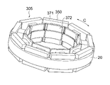
- FIG. 11 is a perspective view showing the configuration of the stator 305 of the electric motor according to Embodiment 3.
- FIG. 12 is an enlarged perspective view showing part of the configuration of stator 305 shown in FIG. 11 and 12, the same or corresponding components as those shown in FIG. 1 are given the same reference numerals as those shown in FIG.
- the electric motor according to Embodiment 3 differs from electric motor 100 according to Embodiment 1 in the shapes of magnetic flux taking-in member 340 and insulator 350 of stator 305 . Except for this point, the electric motor according to the third embodiment is the same as the electric motor 100 according to the first embodiment. Therefore, FIG. 1 will be referred to in the following description.
- the stator 305 has a stator core 20, windings 30 (see FIG. 1), magnetic flux take-in members 340, and insulators 350.
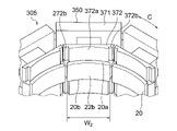
- FIG. 13(a) is an enlarged plan view showing part of the configuration of the stator 305 shown in FIGS. 11 and 12.
- FIG. FIG. 13(b) is a cross-sectional view of part of the structure of the stator 305 shown in FIG. 13(a) taken along line A13-A13.
- the magnetic flux taking-in members 340 are arranged on the end faces 20a and 20b of the stator core 20 in the z-axis direction. As a result, the magnetic flux flowing to the stator 305 can be taken in from the overhang portion 12c (see FIG. 1) of the permanent magnet 12, thereby further preventing the efficiency of the electric motor from being lowered.
- the magnetic flux take-in member 340 has a curved portion 341 having a radially inward concave surface 341a.
- the shape of the curved portion 341 when viewed in the z-axis direction is, for example, an arc shape. This increases the contact area between the stator core 20 and the magnetic flux capturing member 340 compared to a configuration in which the magnetic flux capturing member has a rectangular shape when viewed in the z-axis direction.
- the fixing strength of the member 340 can be improved.
- the curved portion 341 is in contact with the insulator 350 (specifically, the second wall portion 372 described later). This facilitates positioning of the magnetic flux take-in member 340 .
- the magnetic flux take-in member 340 may have a structure in which the curved portion 341 and the bent portion 41 shown in FIGS. 4(a) to 4(d) are combined.
- the protruding portion 342 has a protruding portion 342 which is another bent portion that protrudes from the end portion of the curved portion 341 in the circumferential direction C in a direction away from the permanent magnet 12 (see FIG. 1).
- the projecting portions 342 are provided on both sides of the curved portion 341 in the circumferential direction C.
- the protruding portion 342 protrudes radially outward so that the magnetic flux taking-in member 340 becomes wider in the circumferential direction C. As shown in FIG. As a result, even if magnetic attraction is generated between the permanent magnet 12 and the magnetic flux receiving member 340 during rotation, the magnetic flux receiving member 340 is less likely to come off. Therefore, the reliability of the electric motor can be improved.
- FIG. 14 is a perspective view showing the configuration of the stator core 20 and the insulator 350 shown in FIGS. 11 and 12.
- FIG. FIG. 15 is an enlarged perspective view showing a part of the configuration of stator core 20 and insulator 350 shown in FIG.
- the insulator 350 includes a first wall portion 371 provided radially outside the windings 30 and covering the yoke 21, and a radial wall portion 371 radially extending from the windings 30 (see FIG. 1). and a second wall portion 372 that is provided inside and covers the teeth 22 .
- the second wall portion 372 has a first portion 372a and a second portion 372b.
- the first portion 372a is in contact with the center of the magnetic flux taking-in member 340 in the circumferential direction C (here, the curved portion 341).
- the second portion 372b is provided radially with the end portion (here, the projecting portion 342) of the magnetic flux capturing member 340 in the circumferential direction C with a first gap G1 interposed therebetween.
- the radial position of the magnetic flux capturing member 340 is determined by the contact between the center of the magnetic flux capturing member 340 in the circumferential direction C and the first portion 372a. Therefore, the second portion 372b is provided in the radial direction with respect to the projecting portion 342 with the first gap G1 interposed therebetween. Interference between the wall portion 372 and the projecting portion 342 can be prevented.
- the second wall portion 372 of the insulator 350 is axially provided with the magnetic flux take-in member 340 via the second gap G2.
- the axial position of the magnetic flux capturing member 340 is determined by the contact between the magnetic flux capturing member 340 and the stator core 20 .
- Insulator 350 is provided axially with magnetic flux capturing member 340 with second gap G2 interposed therebetween. interference can be prevented.
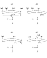
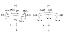
- FIG. 16(a) is a plan view showing the configuration of the magnetic flux taking-in member 340 according to the third embodiment.
- the width W 1 is the width Narrower than W2. That is, the width W1 and the width W2 satisfy the following formula ( 2 ). W1 ⁇ W2 ( 2 ) Thereby, interference between two magnetic flux taking-in members 340 adjacent in the circumferential direction C can be prevented.
- the width W1 and width W are lengths in a direction orthogonal to straight line S.
- FIG. 16(b) to (d) are plan views schematically showing other examples of the configuration of the magnetic flux taking-in member 340 according to the third embodiment.
- the protrusions 342 do not necessarily have a structure that protrudes radially outward from both sides in the circumferential direction C of the magnetic flux capturing member 40 .
- the magnetic flux capturing member 40 may have a projecting portion 342 projecting radially outward from one end in the circumferential direction C.
- FIG. 16(c) the magnetic flux taking-in member 340 does not have a projecting portion 342, and has only a curved portion 341 having a uniform radial thickness t in the circumferential direction C. may This minimizes the size of the magnetic flux receiving member 340 required to capture the magnetic flux of the permanent magnet 12 (see FIG. 1), while facilitating the positioning of the magnetic flux receiving member 340 when it is fixed to the insulator 350. can do.
- the projecting portion 342 may be provided at the center of the magnetic flux taking-in member 340 in the circumferential direction C. Thereby, interference between the projecting portion 342 and another magnetic flux taking-in member 340 adjacent in the circumferential direction C can be prevented.
- the magnetic flux capturing member 340 has the curved portion 341 having the radially inward concave surface 341a.
- the shape of the curved portion 341 when viewed in the z-axis direction is, for example, an arc shape. This increases the contact area between the stator core 20 and the magnetic flux capturing member 340 compared to a configuration in which the magnetic flux capturing member has a rectangular shape when viewed in the z-axis direction.
- the fixing strength of the member 340 can be improved. Further, the positioning of the magnetic flux capturing member 340 when fixing the magnetic flux capturing member 340 to the insulator 350 can be facilitated.
- the protruding portion 342 protrudes radially outward so that the magnetic flux capturing member 340 becomes wider in the circumferential direction C. As a result, even if magnetic attraction is generated between the permanent magnet 12 and the magnetic flux receiving member 340 during rotation, the magnetic flux receiving member 340 is less likely to come off.
- the width W1 in the circumferential direction C of the curved portion 341 is narrower than the width W2 in the circumferential direction C of the tooth tip portion 22b. Therefore, interference between two magnetic flux taking-in members 340 adjacent in the circumferential direction C can be prevented.
- the insulator 350 includes the first portion 372a that abuts on the center of the magnetic flux capturing member 340 in the circumferential direction C, and the radial end of the magnetic flux capturing member 340 in the circumferential direction C. portion (eg, protrusion 342) and a second portion 372b provided across a first gap G1.
- portion eg, protrusion 342
- second portion 372b provided across a first gap G1.
- the insulator 350 is provided axially with the magnetic flux take-in member 340 with the second gap G2 interposed therebetween. Thereby, interference between the insulator 350 and the magnetic flux capturing member 340 can be prevented when the magnetic flux capturing member 340 is positioned in the axial direction.
- FIG. 17(a) is an enlarged cross-sectional view schematically showing a part of the configuration of a magnetic flux take-in member 340A according to Modification 1 of Embodiment 3.
- FIG. 17(a) the same reference numerals as those shown in FIG. 16(a) are attached to the constituent elements that are the same as or correspond to the constituent elements shown in FIG. 16(a).
- the electric motor according to Modification 1 of Embodiment 3 differs from the electric motor according to Embodiment 3 in the shape of magnetic flux intake member 340A of the stator. Except for this point, the electric motor according to the first modification of the third embodiment is the same as the electric motor according to the third embodiment. Therefore, FIG. 14 and the like will be referred to in the following description.
- the magnetic flux take-in member 340A has a curved portion 341 and a projecting portion 342A.
- the protruding portion 342A is a portion of the magnetic flux taking-in member 340A that protrudes by bending the end portion of the curved portion 341 in the circumferential direction C in a direction away from the permanent magnet 12 (see FIG. 1).
- the first direction which is the direction in which the projecting portion 342A protrudes, is not limited to the direction away from the permanent magnet 12, and may be the direction approaching the permanent magnet 12 (for example, see FIG. 17B described later). .
- protrusion 342 protrudes so that width W3 in circumferential direction C of magnetic flux take-in member 340A is constant in the direction away from permanent magnet 12 .
- the side surface 345 of the magnetic flux take-in member 340A extends parallel to the straight line S shown in FIG. 13(a).
- the width W3 in the circumferential direction of the magnetic flux taking - in member 340 can be increased to the width W2 in the circumferential direction C of the tooth tip portion 22b of the tooth 22 . This makes it easier for the magnetic flux taking-in member 340A to take in the magnetic flux generated at the overhang portion 12c of the permanent magnet 12 .
- FIG. 17(b) is a plan view schematically showing another example of the configuration of the magnetic flux take-in member 340A according to Modification 1 of Embodiment 3.
- FIG. 17(b) the protruding portion 342A of the magnetic flux capturing member 340A may protrude toward the permanent magnet 12 (see FIG. 1).
- a fixing member such as an insulator or a molded resin portion is brought into contact with the concave surface 341a of the curved portion 341, thereby preventing the magnetic flux taking-in member 340A from coming off due to the magnetic attraction force. .
- protrusion 342A is arranged in a direction away from permanent magnet 12 or in a direction away from permanent magnet 12 so that width W3 of magnetic flux taking-in member 340A in circumferential direction C is constant. It protrudes in the direction approaching 12. Thereby, interference between two magnetic flux taking-in members 340 adjacent in the circumferential direction C can be prevented. Therefore, the width W3 in the circumferential direction C of the magnetic flux take - in member 340 can be widened to the width W2 in the circumferential direction C of the tooth tip portion 22b of the tooth 22 . This makes it easier for the magnetic flux taking-in member 340A to take in the magnetic flux generated at the overhang portion 12c of the permanent magnet 12 .
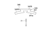
- FIG. 18 is a plan view schematically showing the configuration of a magnetic flux take-in member 340B according to Modification 2 of Embodiment 3.
- the same reference numerals as those shown in FIG. 16(a) are attached to the constituent elements that are the same as or correspond to the constituent elements shown in FIG. 16(a).
- the electric motor according to Modification 2 of Embodiment 3 differs from the electric motor according to Embodiment 3 in the shape of magnetic flux intake member 340B of the stator. Except for this point, the electric motor according to the second modification of the third embodiment is the same as the electric motor according to the third embodiment. Therefore, FIG. 14 will be referred to in the following description.
- the magnetic flux take-in member 340B has a curved portion 341 and a projecting portion 342B.
- the projecting portion 342B is provided at the center of the curved portion 341 in the circumferential direction C.
- the protruding portion 342B becomes wider as the distance from the curved portion 341 increases. Specifically, a side surface 346 of the protruding portion 342B facing the circumferential direction C is inclined such that the protruding portion 342B becomes wider the further away it is from the curved portion 341 .
- the fixing member such as the insulator or the molded resin portion abuts against the side surface 346, thereby improving the fixing strength of the magnetic flux capturing member 340 to the fixing member, thereby preventing the magnetic flux capturing member 340B from falling off due to the magnetic attraction force. can.
Landscapes
- Engineering & Computer Science (AREA)
- Power Engineering (AREA)
- Iron Core Of Rotating Electric Machines (AREA)
Priority Applications (4)
| Application Number | Priority Date | Filing Date | Title |
|---|---|---|---|
| CN202180095596.6A CN116964900A (zh) | 2021-03-18 | 2021-03-18 | 电动机 |
| JP2023506626A JP7515690B2 (ja) | 2021-03-18 | 2021-03-18 | 電動機 |
| US18/262,750 US20240322617A1 (en) | 2021-03-18 | 2021-03-18 | Electric motor |
| PCT/JP2021/011095 WO2022195804A1 (ja) | 2021-03-18 | 2021-03-18 | 電動機 |
Applications Claiming Priority (1)
| Application Number | Priority Date | Filing Date | Title |
|---|---|---|---|
| PCT/JP2021/011095 WO2022195804A1 (ja) | 2021-03-18 | 2021-03-18 | 電動機 |
Publications (1)
| Publication Number | Publication Date |
|---|---|
| WO2022195804A1 true WO2022195804A1 (ja) | 2022-09-22 |
Family
ID=83321996
Family Applications (1)
| Application Number | Title | Priority Date | Filing Date |
|---|---|---|---|
| PCT/JP2021/011095 Ceased WO2022195804A1 (ja) | 2021-03-18 | 2021-03-18 | 電動機 |
Country Status (4)
| Country | Link |
|---|---|
| US (1) | US20240322617A1 (https=) |
| JP (1) | JP7515690B2 (https=) |
| CN (1) | CN116964900A (https=) |
| WO (1) | WO2022195804A1 (https=) |
Families Citing this family (1)
| Publication number | Priority date | Publication date | Assignee | Title |
|---|---|---|---|---|
| JP7483150B2 (ja) * | 2021-08-30 | 2024-05-14 | 三菱電機株式会社 | 電動機 |
Citations (2)
| Publication number | Priority date | Publication date | Assignee | Title |
|---|---|---|---|---|
| JP2010220271A (ja) * | 2009-03-12 | 2010-09-30 | Denso Corp | 電動モータ |
| JP2015119516A (ja) * | 2013-12-16 | 2015-06-25 | アスモ株式会社 | ステータコア、ステータ、及びモータ |
Family Cites Families (3)
| Publication number | Priority date | Publication date | Assignee | Title |
|---|---|---|---|---|
| WO2016208629A1 (ja) * | 2015-06-24 | 2016-12-29 | 三菱電機株式会社 | 回転電機の固定子、回転電機、回転電機の固定子の製造方法 |
| DE112019001951T5 (de) * | 2018-04-13 | 2021-01-21 | Mitsubishi Electric Corporation | Stator für elektrische rotationsmaschine, elektrische rotationsmaschine sowie herstellungsverfahren für stator für elektrische rotationsmaschine |
| EP4300794A4 (en) * | 2021-02-25 | 2024-04-24 | Mitsubishi Electric Corporation | ELECTRIC MOTOR |
-
2021
- 2021-03-18 JP JP2023506626A patent/JP7515690B2/ja active Active
- 2021-03-18 WO PCT/JP2021/011095 patent/WO2022195804A1/ja not_active Ceased
- 2021-03-18 CN CN202180095596.6A patent/CN116964900A/zh not_active Withdrawn
- 2021-03-18 US US18/262,750 patent/US20240322617A1/en not_active Abandoned
Patent Citations (2)
| Publication number | Priority date | Publication date | Assignee | Title |
|---|---|---|---|---|
| JP2010220271A (ja) * | 2009-03-12 | 2010-09-30 | Denso Corp | 電動モータ |
| JP2015119516A (ja) * | 2013-12-16 | 2015-06-25 | アスモ株式会社 | ステータコア、ステータ、及びモータ |
Also Published As
| Publication number | Publication date |
|---|---|
| JPWO2022195804A1 (https=) | 2022-09-22 |
| CN116964900A (zh) | 2023-10-27 |
| US20240322617A1 (en) | 2024-09-26 |
| JP7515690B2 (ja) | 2024-07-12 |
Similar Documents
| Publication | Publication Date | Title |
|---|---|---|
| JP6328319B2 (ja) | 電機子および回転電機 | |
| CN104106199B (zh) | 旋转电机 | |
| JP6461381B2 (ja) | 回転電機の固定子、回転電機、および、回転電機の固定子の製造方法 | |
| EP3687043B1 (en) | Insulator, and stator and motor comprising same | |
| KR101384417B1 (ko) | 회전 전기기계 | |
| US7474028B2 (en) | Motor | |
| US10855123B2 (en) | Rotating electrical machine and producing method of rotating electrical machine | |
| JP7422931B2 (ja) | 電動機 | |
| JPH11122855A (ja) | ステータ用コイルボビンと電動機 | |
| WO2022195804A1 (ja) | 電動機 | |
| JP7166207B2 (ja) | 回転電機およびその製造方法 | |
| JP6416417B2 (ja) | 回転電機の固定子、回転電機、および回転電機の固定子の製造方法 | |
| JP2020010539A (ja) | ロータ、及びブラシレスモータ | |
| WO2023203633A1 (ja) | 固定子、電動機及び送風機 | |
| JP7780305B2 (ja) | モータ | |
| JP2021164273A (ja) | モータ | |
| WO2019064747A1 (ja) | ロータ及びそのロータを備えたモータ | |
| US20230155431A1 (en) | Motor | |
| KR20190055530A (ko) | 로터 및 이를 포함하는 모터 | |
| JPWO2022264787A5 (https=) | ||
| CN119675303A (zh) | 绝缘体结构 | |
| WO2021210249A1 (ja) | 回転子及び電動機 | |
| JPWO2021210249A5 (https=) | ||
| JPWO2019146451A1 (ja) | インシュレータ及びそれを備えたステータ、モータ |
Legal Events
| Date | Code | Title | Description |
|---|---|---|---|
| 121 | Ep: the epo has been informed by wipo that ep was designated in this application |
Ref document number: 21931554 Country of ref document: EP Kind code of ref document: A1 |
|
| ENP | Entry into the national phase |
Ref document number: 2023506626 Country of ref document: JP Kind code of ref document: A |
|
| WWE | Wipo information: entry into national phase |
Ref document number: 18262750 Country of ref document: US |
|
| WWE | Wipo information: entry into national phase |
Ref document number: 202180095596.6 Country of ref document: CN |
|
| NENP | Non-entry into the national phase |
Ref country code: DE |
|
| 122 | Ep: pct application non-entry in european phase |
Ref document number: 21931554 Country of ref document: EP Kind code of ref document: A1 |