WO2023203633A1 - 固定子、電動機及び送風機 - Google Patents
固定子、電動機及び送風機 Download PDFInfo
- Publication number
- WO2023203633A1 WO2023203633A1 PCT/JP2022/018128 JP2022018128W WO2023203633A1 WO 2023203633 A1 WO2023203633 A1 WO 2023203633A1 JP 2022018128 W JP2022018128 W JP 2022018128W WO 2023203633 A1 WO2023203633 A1 WO 2023203633A1
- Authority
- WO
- WIPO (PCT)
- Prior art keywords
- stator
- magnetic flux
- winding
- electric motor
- stator core
- Prior art date
Links
- 230000004907 flux Effects 0.000 claims abstract description 149
- 238000004804 winding Methods 0.000 claims abstract description 128
- 238000013459 approach Methods 0.000 claims description 12
- 229910000831 Steel Inorganic materials 0.000 claims description 8
- 239000010959 steel Substances 0.000 claims description 8
- 230000007423 decrease Effects 0.000 abstract description 12
- 239000012212 insulator Substances 0.000 description 102
- 230000004048 modification Effects 0.000 description 31
- 238000012986 modification Methods 0.000 description 31
- 239000011347 resin Substances 0.000 description 20
- 229920005989 resin Polymers 0.000 description 20
- 230000000694 effects Effects 0.000 description 11
- 229910052782 aluminium Inorganic materials 0.000 description 7
- XAGFODPZIPBFFR-UHFFFAOYSA-N aluminium Chemical compound [Al] XAGFODPZIPBFFR-UHFFFAOYSA-N 0.000 description 7
- 230000004323 axial length Effects 0.000 description 5
- XEEYBQQBJWHFJM-UHFFFAOYSA-N Iron Chemical compound [Fe] XEEYBQQBJWHFJM-UHFFFAOYSA-N 0.000 description 4
- 229910052751 metal Inorganic materials 0.000 description 4
- 239000002184 metal Substances 0.000 description 4
- RYGMFSIKBFXOCR-UHFFFAOYSA-N Copper Chemical compound [Cu] RYGMFSIKBFXOCR-UHFFFAOYSA-N 0.000 description 3
- 239000000696 magnetic material Substances 0.000 description 3
- 238000005096 rolling process Methods 0.000 description 3
- 230000008859 change Effects 0.000 description 2
- 229910052742 iron Inorganic materials 0.000 description 2
- 238000000034 method Methods 0.000 description 2
- 230000002093 peripheral effect Effects 0.000 description 2
- 230000008569 process Effects 0.000 description 2
- 230000009467 reduction Effects 0.000 description 2
- 229910000859 α-Fe Inorganic materials 0.000 description 2
- 229910000838 Al alloy Inorganic materials 0.000 description 1
- 230000003247 decreasing effect Effects 0.000 description 1
- 238000001746 injection moulding Methods 0.000 description 1
- 238000003780 insertion Methods 0.000 description 1
- 230000037431 insertion Effects 0.000 description 1
- 238000009413 insulation Methods 0.000 description 1
- WABPQHHGFIMREM-UHFFFAOYSA-N lead(0) Chemical compound [Pb] WABPQHHGFIMREM-UHFFFAOYSA-N 0.000 description 1
- 239000000463 material Substances 0.000 description 1
- 239000007769 metal material Substances 0.000 description 1
- 238000000465 moulding Methods 0.000 description 1
- 229920001187 thermosetting polymer Polymers 0.000 description 1
Images


Classifications
-
- H—ELECTRICITY
- H02—GENERATION; CONVERSION OR DISTRIBUTION OF ELECTRIC POWER
- H02K—DYNAMO-ELECTRIC MACHINES
- H02K3/00—Details of windings
- H02K3/32—Windings characterised by the shape, form or construction of the insulation
- H02K3/34—Windings characterised by the shape, form or construction of the insulation between conductors or between conductor and core, e.g. slot insulation
Definitions
- the present disclosure relates to a stator, a motor, and a blower.
- Patent Document 1 has a problem in that the insulating part is deformed due to stress generated in the insulating part when the winding is wound. When the deformed insulation presses on the extension and the extension comes into contact with the rotor, noise is generated.
- the present disclosure aims to suppress deformation of an insulating member in a stator.
- a stator includes a stator main body including a stator core and a magnetic flux intake member provided at an axial end of the stator core, and a winding wound around the stator core. and a first insulating member that insulates the stator main body and the winding, and the first insulating member includes a first insulating member provided between the magnetic flux intake member and the winding. The thickness of the first portion in the radial direction of the stator core becomes thinner toward the end of the first insulating member in the axial direction.
- An electric motor includes the stator and rotor described above.
- a blower according to another aspect of the present disclosure includes the above-described electric motor and an impeller driven by the electric motor.
- deformation of the insulating member in the stator can be suppressed.
- FIG. 1 is a partial side view schematically showing a part of the configuration of an electric motor according to Embodiment 1.
- FIG. FIG. 2 is a cross-sectional view of the stator shown in FIG. 1 taken along line A2-A2.
- FIG. 3 is a perspective view showing a part of the structure of the stator main body shown in FIGS. 1 and 2.
- FIG. 3 is a cross-sectional view schematically showing a part of the structure of the stator shown in FIGS. 1 and 2.
- FIG. FIG. 5 is an enlarged sectional view showing the configuration around the magnetic flux intake member shown in FIG. 4.
- FIG. FIG. 3 is a cross-sectional view schematically showing a part of the configuration of a stator according to Modification 1 of Embodiment 1.
- FIG. 7 is a cross-sectional view schematically showing a part of the structure of a stator according to a second modification of the first embodiment.
- FIG. FIG. 3 is a cross-sectional view schematically showing a part of the structure of a stator according to a second embodiment.
- FIG. 7 is a cross-sectional view schematically showing a part of the structure of a stator according to a modification of the second embodiment.
- FIG. 7 is a cross-sectional view schematically showing a part of the configuration of an electric motor according to a third embodiment.
- FIG. 7 is a cross-sectional view schematically showing a part of the structure of a stator according to a fourth embodiment.
- FIG. 7 is a cross-sectional view schematically showing a part of the structure of a stator according to a modification of the fourth embodiment.
- FIG. 7 is a partial cross-sectional view schematically showing the configuration of a blower according to a fifth embodiment.
- the z-axis is a coordinate axis parallel to the axis of the motor rotor shaft.
- the x-axis is a coordinate axis perpendicular to the z-axis.
- the y-axis is a coordinate axis perpendicular to both the x-axis and the z-axis.
- FIG. 1 is a partial side view schematically showing a part of the configuration of electric motor 100 according to the first embodiment.
- electric motor 100 includes a stator 1 and a rotor 5.
- the rotor 5 is arranged inside the stator 1. That is, the electric motor 100 is an inner rotor type electric motor.
- the rotor 5 has a shaft 51 as a rotating shaft and a permanent magnet 52 as a rotor body.
- the rotor 5 is rotatable around the axis A of the shaft 51.
- a direction along the circumference of a circle centered on the axis A of the shaft 51 will be referred to as a "circumferential direction C.”
- the z-axis direction is also called the "axial direction”
- the direction orthogonal to the axial direction is also called the "radial direction”.
- the permanent magnet 52 is attached to the shaft 51.
- the permanent magnet 52 is a cylindrical magnet that is long in the z-axis direction.
- N poles and S poles are alternately formed.
- the rotor body of the rotor 5 may include a rotor core fixed to the shaft 51 and a permanent magnet attached to the rotor core.
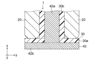
- FIG. 2 is a cross-sectional view of the stator 1 shown in FIG. 1 taken along the line A2-A2.
- the stator 1 includes a stator main body 10, a winding 20, and an insulator 30 as a first insulating member.
- FIG. 3 is a perspective view showing a part of the structure of the stator main body 10 shown in FIGS. 1 and 2. As shown in FIG. 3, the stator main body 10 includes a stator core 40 and magnetic flux intake members 61 and 62.
- the stator core 40 has a yoke 41 extending in the circumferential direction C and a plurality of teeth 42.
- the plurality of teeth 42 are arranged at predetermined intervals in the circumferential direction C.
- a slot 43 which is a space in which the winding 20 and the insulator 30 (see FIGS. 1 and 2) are accommodated, is provided between two teeth 42 adjacent to each other in the circumferential direction C among the plurality of teeth 42.
- the plurality of teeth 42 face the rotor 5 (see FIG. 1) in the radial direction.
- Each tooth 42 of the plurality of teeth 42 has a tooth main body portion 42a and a tooth tip portion 42b.
- the teeth main body portion 42a extends radially inward from the yoke 41.
- the winding 20 (see FIG. 2) is wound around the tooth body portion 42a via the insulator 30.
- the tooth tip portion 42b is disposed radially inside the tooth body portion 42a, and is wider in the circumferential direction C than the tooth body portion 42a.
- the tooth tip portion 42b has an end face 42c facing the +z-axis direction and an end face 42d facing the ⁇ z-axis direction. End surfaces 42c and 42d on both sides in the z-axis direction of the tooth tip portion 42b constitute ends of the stator core 40 in the z-axis direction.
- the stator core 40 has an end face 40a facing the +z-axis direction, which is one end face in the axial direction, and an end face 40b facing the ⁇ z-axis direction, which is the other end face in the axial direction.
- the above-mentioned permanent magnet 52 has an end face 52a that is one end face in the axial direction, which faces the +z-axis direction, and an end face 52b, which is the other end face, that faces the ⁇ z-axis direction.
- the first length (hereinafter also referred to as "axial length") of the stator core 40 in the z-axis direction is L1
- the second length of the permanent magnet 52 in the z-axis direction is L2.
- the length L1 is shorter than the length L2. That is, the length L1 and the length L2 satisfy the following formula (1). L1 ⁇ L2 (1)
- FIG. 4 is a cross-sectional view schematically showing a part of the structure of the stator 1 shown in FIGS. 1 and 2.
- the stator core 40 has a plurality of electromagnetic steel plates 45 stacked in the z-axis direction. Since the length L1 of the stator core 40 in the z-axis direction is shorter than the length L2 of the permanent magnet 52 in the z-axis direction, the number of electromagnetic steel plates 45 is reduced, so that the cost of the stator core 40 can be reduced. can. Therefore, the cost of electric motor 100 can be reduced. Furthermore, since the length (circumferential length) of the winding 20 is also shortened, the resistance value of the winding 20 can be reduced. Therefore, reduction in loss in the electric motor 100 can be prevented. That is, the efficiency of electric motor 100 can be improved.
- the end face 40a facing the +z-axis direction and the end face 40b facing the ⁇ z-axis direction of the stator core 40 are the same as the end face 52a facing the +z-axis direction and the end face 52b facing the ⁇ z-axis direction of the permanent magnet 52. is located between.
- at least one end surface of the end surface 40a facing the +z-axis direction and the end surface 40b facing the ⁇ z-axis direction of the stator core 40 faces the ⁇ z-axis direction with the end surface 52a of the permanent magnet 52 facing the +z-axis direction. It suffices if it is disposed between the end surface 52b and the end surface 52b.
- the end surface 40b of the stator core 40 facing the -z-axis direction may be located axially outside the end surface 52b of the permanent magnet 52 facing the -z-axis direction.
- the length L1 of the stator core 40 in the z-axis direction is shorter than the length L2 of the permanent magnet 52 in the z-axis direction.
- the axial length of the stator core and the rotor body are the same.
- permanent magnets with high magnetic force are expensive.
- an inexpensive permanent magnet with low magnetic force for example, a ferrite magnet
- the volume of the motor becomes large in order to compensate for the decrease in magnetic force. Therefore, the cost of the electromagnetic steel plate 45 (see FIG. 4) and the winding increases.
- the length L1 of the stator core 40 in the z-axis direction is shorter than the length L2 of the permanent magnet 52 in the z-axis direction. Since the number of electromagnetic steel plates 45 provided in the stator core 40 is reduced, the cost of the stator core 40 can be reduced. Therefore, the cost of electric motor 100 can be reduced.
- the length of the stator core in the z-axis direction is made shorter than the length of the rotor main body (permanent magnet 52 in the first embodiment) in the z-axis direction, the magnetic flux of the permanent magnets taken into the stator core Since the amount decreases, the efficiency of the electric motor decreases.
- the magnetic flux generated at the end of the rotor body in the z-axis direction that does not face the stator core in the radial direction (hereinafter also referred to as an "overhang") becomes difficult to flow to the stator core. In this way, when the amount of magnetic flux flowing from the rotor body to the stator core decreases, the output and efficiency of the motor may decrease.
- the stator main body 10 has magnetic flux capturing members 61 and 62 made of a magnetic material that captures the magnetic flux of the permanent magnet 52. This makes it easier for the magnetic flux generated in the overhang portion of the permanent magnet 52 to flow to the stator core 40 and the winding 20 via the magnetic flux intake members 61 and 62. Therefore, according to the first embodiment, it is possible to reduce the cost of electric motor 100 while preventing a decrease in the output and efficiency of electric motor 100. Therefore, even if an inexpensive low-magnetic-force magnet (for example, a ferrite magnet) is used as the permanent magnet 52 in the rotor 5 of the electric motor 100, the magnetic flux intake members 61 and 62 will not absorb the magnetic flux of the permanent magnet.
- an inexpensive low-magnetic-force magnet for example, a ferrite magnet
- the magnetic flux intake members 61 and 62 are, for example, metal pieces made of a metal material. Specifically, the magnetic flux intake members 61 and 62 are iron pieces made of iron.
- the plurality of magnetic flux intake members 61 and 62 are arranged at intervals in the circumferential direction C. Specifically, the magnetic flux intake member 61 is arranged on the end face 42c of the tooth tip 42b facing the +z-axis direction, and the magnetic flux intake member 62 is arranged on the end face 42d of the tooth tip 42b facing the ⁇ z-axis direction. has been done.
- the magnetic flux intake members 61 and 62 are arranged at the tooth tip portions 42b of the teeth 42.
- the magnetic flux capturing members 61, 62 are arranged closer to the permanent magnet 52 (see FIG. 1).
- the magnetic flux of the permanent magnet 52 is easily captured by the magnetic flux capture members 61 and 62.
- the magnetic flux intake members 61 and 62 will be collectively referred to as the "magnetic flux intake member 60.” Note that, as shown in FIG.
- the stator main body 10 can be realized without having the magnetic flux intake member 62.
- the magnetic flux intake member 60 may be disposed on at least one of the end surfaces 42c facing the +z-axis direction and the end surface 42d facing the ⁇ z-axis direction of the tooth tip 42b.
- the configuration of the insulator 30 will be explained using FIGS. 2, 4, and 5.
- the insulator 30 is provided between the stator main body 10 and the winding 20. Insulator 30 insulates stator main body 10 and winding 20.
- the insulator 30 has a first insulating part 30a and a second insulating part 30b.
- the first insulating portion 30 a is a portion of the insulator 30 that insulates the tooth tip portion 42 b and the winding 20 and insulates the magnetic flux intake member 60 and the winding 20 .
- the second insulating portion 30b is a portion of the insulator 30 that insulates the tooth body portion 42a and the winding 20.
- stator main body 10 includes the magnetic flux intake member 60, it is possible to reduce the cost of the stator 1 and prevent a decrease in the efficiency and output of the electric motor 100.
- stress from the winding 20 acts on the surface of the first insulating portion 30a of the insulator 30 that faces the winding 20 (that is, the radially outward facing surface 31). Stress (hereinafter also referred to as “winding stress F 1 , F 2 ”) generated on the radially outward surface 31 of the insulator 30 occurs when the winding 20 is wound around the teeth 42 .
- the insulator 30 may be deformed due to winding stress. Specifically, the radially outward surface 31 of the insulator 30 may fall toward the magnetic flux intake member 61 due to winding stress. In this case, when the insulator 30 contacts the magnetic flux intake member 61 and presses the magnetic flux intake member 60, the magnetic flux intake member 61 also deforms toward the rotor 5, and the magnetic flux intake member 61 and the rotor 5 may come into contact.
- the teeth 42 are difficult to deform. This is because the teeth 42 have a T-shape when viewed in the z-axis direction and have a large moment of inertia. Therefore, the portion of the insulator 30 that is supported by the teeth 42 (specifically, the teeth tips 42b) is unlikely to be deformed by the winding stress F2 .
- the shape of the magnetic flux intake member 61 when viewed in the z-axis direction is rectangular, the moment of inertia of the magnetic flux intake member 61 is smaller than the moment of inertia of the tooth 42 . Therefore, a portion of the insulator 30 that overlaps with the magnetic flux intake member 61 in the z-axis direction is easily deformed.
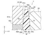
- FIG. 5 is an enlarged sectional view showing the configuration around the magnetic flux intake member 61 shown in FIG. 4.
- the thickness in the radial direction of the first portion 33 which is the portion of the insulator 30 provided between the magnetic flux intake member 61 and the winding 20
- the thickness t1 becomes thinner toward the end portion 30e of the insulator 30 in the z-axis direction (that is, the end portion facing outward in the axial direction).
- the thickness t1 becomes thinner toward the end 30e of the insulator 30 in the z-axis direction.
- the winding stress F1 acting on the insulator 30 can be reduced.
- the thickness t1 is thinner than the thickness t2.
- the radially outward surface 31 of the insulator 30 has a first inclined portion 31a.
- the first inclined portion 31a is inclined such that the closer it gets to the end 30e of the insulator 30 in the z-axis direction, the closer the radial position is to the magnetic flux intake member 60 (that is, the farther away from the winding 20).
- the first inclined portion 31a is inclined such that the closer it gets to the end 30e of the insulator 30 in the z-axis direction, the shorter the radial distance from the axis A (FIG. 1). .
- the first inclined portion 31a is provided in a portion of the radially outward surface 31 of the insulator 30 that overlaps with the magnetic flux intake member 61 in the z-axis direction.
- the winding stress F1 acting on the first inclined portion 31a is lower than the winding stress F2 acting on the portion of the radially outward facing surface 31 where the position in the z-axis direction overlaps with the teeth 42 . be able to. Therefore, since the insulator 30 is less likely to be deformed by the winding stress F1 , the magnetic flux intake member 61 and the rotor 5 are less likely to come into contact with each other. Therefore, generation of noise in electric motor 100 can be suppressed.
- the surface 32 of the insulator 30 facing the magnetic flux intake member 61 (that is, the surface facing inward in the radial direction) has the second inclined portion 32a.
- the second inclined portion 32a is inclined so that the closer the second inclined portion 32a is to the end 30e of the insulator 30 in the z-axis direction, the closer the radial position is to the winding 20 (that is, the farther away from the magnetic flux intake member 60).
- the second inclined portion 32a is inclined such that the radial distance from the axis A (FIG. 1) increases as it approaches the end 30e of the insulator 30 in the z-axis direction. .
- the second inclined portion 32a is provided at a portion of the radially inward surface 32 of the insulator 30 that overlaps with the magnetic flux intake member 61 in the z-axis direction. This makes it difficult for the insulator 30 and the magnetic flux intake member 61 to come into contact with each other. Therefore, the generation of noise in the electric motor 100 can be further suppressed.
- the insulator 30 has the first slope portion 61a and the second slope portion 62a.
- the radial thickness t1 of the first portion 33 of the insulator 30 provided between the magnetic flux intake member 61 and the winding 20 increases as it approaches the end 30e of the insulator 30 in the z-axis direction. , is thinner.
- the insulator 30 can be realized even if it has one of the first slope portion 61a and the second slope portion 62a.
- the insulator 30 has a first portion 33 that insulates the magnetic flux intake member 60 and the winding 20, and a second portion 34 that insulates the stator core 40 and the winding 20, which are separate bodies. Good too.
- the thickness t1 becomes thinner as it approaches the end of the insulator 30 in the z-axis direction. You can leave it there.
- the winding 20 is wound around the teeth 42 of the stator core 40.
- the winding 20 is, for example, aluminum wire, which is cheaper than copper wire. Therefore, the cost of electric motor 100 can be reduced.
- the axial length of stator core 40 ie, length L1
- the axial length of permanent magnet 52 ie, length L2
- the resistance value of the winding 20 also becomes smaller.
- the length L1 of the stator core 40 in the z-axis direction is shorter than the length L2 of the permanent magnet 52 in the z-axis direction. This reduces the number of electromagnetic steel sheets 45 used in the stator core 40, so the cost of the stator 1 can be reduced. Therefore, the cost of electric motor 100 can be reduced.
- the stator 1 includes a magnetic flux capturing member 60 made of a magnetic material that captures the magnetic flux of the permanent magnet 52.
- the magnetic flux generated at the overhang portion of the permanent magnet 52 flows to the stator core 40 and the winding 20 via the magnetic flux intake member 60. Therefore, a decrease in the amount of magnetic flux flowing from the permanent magnet 52 to the stator 1 can be suppressed. Therefore, a decrease in the output and efficiency of electric motor 100 can be suppressed.
- the insulator 30 has the first portion 33 provided between the magnetic flux intake member 60 and the winding 20, and the thickness of the first portion 33 in the radial direction is t1 becomes thinner toward the end 30e of the insulator 30 in the z-axis direction.
- the winding stress F1 acting on the insulator 30 can be reduced. Therefore, deformation of the insulator 30 due to the winding stress F 1 (that is, falling toward the magnetic flux intake member 60 side) can be suppressed. Therefore, since the magnetic flux intake member 60 also becomes difficult to deform, it becomes difficult for the magnetic flux intake member 60 and the rotor 5 to come into contact with each other, so that the generation of noise in the electric motor 100 can be suppressed.
- the radially outward surface 31 of the insulator 30, which is the surface facing the winding 20, has the first inclined portion 31a.
- the first inclined portion 31a is inclined so that its radial position approaches the magnetic flux intake member 60 (that is, moves away from the winding 20) as it approaches the end 30e of the insulator 30 in the +z-axis direction. This makes it difficult for the insulator 30 to be deformed by the winding stress F1 , making it difficult for the magnetic flux intake member 60 and the rotor 5 to come into contact with each other. Therefore, the generation of noise in the electric motor 100 can be suppressed.
- the radially inward surface 32 of the insulator 30, which is the surface facing the magnetic flux intake member 60, has the second inclined portion 32a.
- the second inclined portion 32a is inclined so that the closer it is to the end 30e of the insulator 30 in the +z-axis direction, the closer the radial position is to the winding 20 (that is, the farther away from the magnetic flux intake member 60). This makes it difficult for the insulator 30 and the magnetic flux intake member 60 to come into contact with each other. Therefore, the generation of noise in the electric motor 100 can be further suppressed.
- the electric motor 100 is an inner rotor type electric motor is explained as an example, but even if it is an outer rotor type electric motor in which the rotor 5 is disposed outside the stator 1, The above effects can be achieved.
- FIG. 6 is a cross-sectional view schematically showing a part of the configuration of a stator 1A according to a first modification of the first embodiment.
- components that are the same as or correspond to those shown in FIG. 4 are given the same reference numerals as those shown in FIG.
- Stator 1A according to Modification 1 of Embodiment 1 differs from stator 1 according to Embodiment 1 in the shape of magnetic flux intake member 60A.
- the stator 1A according to the first modification of the first embodiment is the same as the stator 1 according to the first embodiment. Therefore, in the following description, reference will be made to FIG.
- the stator 1A includes a stator main body 10A, a winding 20, and an insulator 30.
- the stator main body 10A includes a stator core 40 including teeth 42, and a magnetic flux intake member 60A disposed on an end surface 42c of the tooth tip 42b facing the +z-axis direction.
- the radially outward facing surface 60c of the magnetic flux intake member 60A is in contact with the second inclined portion 32a of the insulator 30. This makes it difficult for the magnetic flux intake member 60A to come into contact with the rotor 5 (see FIG. 1). Therefore, the generation of noise in the stator 1A can be further suppressed.
- the radially inward surface 60d of the magnetic flux intake member 60A is inclined so that the radial position approaches the winding 20 as it approaches the end 60e of the magnetic flux intake member 60A in the +z-axis direction.
- the radially inward surface 60d is located closer to the insulator 30 than the cylindrical surface S including the radially inward surface 42e of the tooth tip 42b. This makes it difficult for the magnetic flux intake member 60A to come into contact with the rotor 5 (see FIG. 1). Therefore, the generation of noise in the stator 1A can be further suppressed.
- FIG. 7 is a sectional view schematically showing a part of the configuration of a stator 1B according to a second modification of the first embodiment.
- components that are the same as or correspond to those shown in FIG. 4 are given the same reference numerals as those shown in FIG.
- the stator 1B according to the second modification of the first embodiment differs from the stator 1 according to the first embodiment in that it further includes a molded resin part 70.
- the stator 1B according to the second modification of the first embodiment is the same as the stator 1 according to the first embodiment.
- the stator 1B includes a stator main body 10, a winding 20, an insulator 30, and a molded resin part 70 as a second insulating member.
- the mold resin part 70 is made of, for example, a thermosetting resin.
- the mold resin part 70 is molded, for example, by injection molding. Moreover, the molded resin part 70 is integrated with the stator main body 10, the winding 20, and the insulator 30 by integral molding.
- the molded resin part 70 fixes the magnetic flux intake member 60 to the stator core 40. This improves the rigidity of the stator main body 10, so that vibration of the magnetic flux intake member 60 due to electromagnetic force can be suppressed. Therefore, it is possible to realize a reduction in noise of the electric motor having the stator 1B.
- the molded resin part 70 fixes the insulator 30 to the stator core 40. Thereby, deformation of the insulator 30 due to winding stress can be further suppressed.
- the molded resin part 70 fixes the winding 20 to the stator core 40. This prevents the winding 20 from vibrating due to magnetic force or Lorentz force when energized, so it is possible to further suppress the generation of noise in the stator 1B.
- the winding wire 20 is an aluminum wire
- the tensile strength of the aluminum wire is lower than the tensile strength of the copper wire. Therefore, the tensile strength during the winding operation of the winding 20 around the stator core 40 is reduced, and the force for fixing the winding 20 to the stator core 40 is reduced.
- the winding 20 tends to vibrate.
- the molded resin part 70 covers the winding 20. Thereby, even if a current is applied to the winding 20 made of aluminum wire, vibration of the winding 20 can be suppressed.
- the winding 20 is an aluminum wire and the winding 20 is covered with the molded resin part 70, the cost of the stator 1B can be further reduced, and the generation of noise in the stator 1B can be further suppressed. can do.
- the winding 20 may be an aluminum alloy wire having a tensile strength greater than that of the aluminum wire.
- the stator 1B further includes a molded resin portion 70 that fixes the magnetic flux intake member 60 to the stator core 40. This improves the rigidity of the stator main body 10, so that vibration of the magnetic flux intake member 60 due to electromagnetic force can be suppressed.
- the molded resin portion 70 fixes the insulator 30 to the stator core 40. Thereby, deformation of the insulator 30 due to winding stress can be further suppressed.
- the molded resin portion 70 fixes the winding 20 to the stator core 40. This prevents the winding 20 from vibrating due to magnetic force or Lorentz force when energized, so that the generation of noise in the stator 1B can be further suppressed.
- FIG. 8 is a cross-sectional view schematically showing a part of the structure of the stator 2 according to the second embodiment.
- components that are the same as or correspond to those shown in FIG. 4 are given the same reference numerals as those shown in FIG.
- the stator 2 according to the second embodiment differs from the stator 1 according to the first embodiment in the shape of the insulator 230.
- the stator 2 according to the second embodiment is the same as the stator 1 according to the first embodiment. Therefore, in the following description, reference will be made to FIG.
- the stator 2 includes a stator main body 10, a winding 20, and an insulator 230.
- the radial position of the entire radially outward facing surface 231 of the insulator 230 (that is, the surface facing the winding 20) approaches the magnetic flux intake member 60 as it approaches the end 30e of the insulator 230 in the +z-axis direction. (i.e., away from winding 20).
- the radially outward surface 231 of the insulator 230 is arranged such that the closer it gets to the +z-axis end 30e of the insulator 230, the shorter the radial distance from the axis A (FIG. 1). It is sloping.
- the winding stresses F 11 , F 12 , F 13 acting on the radially outward facing surface 231 become smaller as they get closer to the end 30e in the +z-axis direction. Therefore, compared to the configuration shown in FIG. 4, the stress acting on the portion of the radially outward facing surface 231 where the boundary between the magnetic flux intake member 60 and the stator core 40 overlaps in the z-axis direction can be reduced. can be reduced. Therefore, since the insulator 230 becomes difficult to deform due to winding stress, it becomes difficult for the magnetic flux intake member 60 and the rotor 5 (see FIG. 1) to come into contact with each other. Therefore, generation of noise in the stator 2 can be suppressed.
- the winding 20 has a protrusion (that is, a coil end) 21 that covers an end surface 230c of the insulator 230 facing in the +z-axis direction.
- the axial height H2 of the radially inner portion of the protrusion 21 from the end surface 230c is the axial height H2 of the radially central portion of the protrusion 21 from the end surface 230c. Lower than H 1 .
- the axial height of the protrusion 21 of the winding 20 from the end surface 230c decreases as it approaches the radially outward surface 231 of the insulator 230.
- the winding 20 has the protrusion 21 that protrudes in the axial direction from the end face 230c of the insulator 230 facing the +z-axis direction, and the height of the radially inner portion of the protrusion 21 is increased.
- the height H 2 is lower than the height H 1 of the radially central portion of the protrusion 21 .
- FIG. 9 is a cross-sectional view schematically showing a part of the configuration of a stator 2A according to a modification of the second embodiment.
- components that are the same as or correspond to those shown in FIG. 8 are given the same reference numerals as those shown in FIG.
- the stator 2A according to the modification of the second embodiment differs from the stator 2 according to the second embodiment in that a gap d is provided between the insulator 230 and the winding 20.
- the stator 2A according to the modification of the second embodiment is the same as the stator 2 according to the second embodiment.
- a gap d is provided between the insulator 230 and the winding 20 in the radial direction. Specifically, a gap d is created between the winding 20 and a portion of the radially outward facing surface 231 of the insulator 230 where the +z-axis facing end surface 42c of the tooth tip 42b overlaps in the z-axis direction. is provided. This makes it difficult for winding stress to act on the insulator 230. Therefore, deformation of the insulator 230 due to winding stress can be further suppressed.
- a gap d is provided between the insulator 230 and the winding 20.
- deformation of the insulator 230 due to winding stress can be further suppressed. Therefore, since the magnetic flux intake member 60 also becomes difficult to deform, it becomes difficult for the magnetic flux intake member 60 and the rotor 5 to come into contact with each other, so that it is possible to suppress the generation of noise in the electric motor.
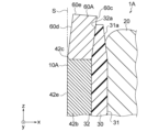
- FIG. 10 is a cross-sectional view schematically showing a part of the configuration of electric motor 300 according to the third embodiment.
- the electric motor 300 according to the third embodiment is different from the electric motor 100 according to the first embodiment in that the stator 3 does not have the magnetic flux intake member 62.
- electric motor 300 according to the third embodiment is the same as electric motor 100 according to the first embodiment. Therefore, in the following description, reference is made to FIGS. 1 and 2.
- the electric motor 300 has a stator 3 and a rotor 5.
- the stator 3 includes a stator main body 310, a winding 20, and an insulator 30.
- the stator main body 310 has a stator core 40 and a magnetic flux intake member 61.
- the stator 3 only has the magnetic flux intake member 61 disposed on the end surface 42c of the tooth tip 42b facing the +z-axis direction. Thereby, the number of parts in the electric motor 300 can be reduced, and the assembly process of the electric motor 300 can be simplified.
- a portion 32c of the radially inward surface 32 of the insulator 30 facing the magnetic flux intake member 61 and a portion 32c opposite to the radially inward surface 32b of the tooth tip 42b is arranged closer to the winding 20 than the surface 42e. This increases the distance between the outer circumferential surface 52c of the permanent magnet 52 and the radially inward surface 32 of the insulator 30. Therefore, even if the insulator 30 is deformed by winding stress, contact between the radially inward surface 32 of the insulator 30 and the rotor 5 can be prevented.
- the magnetic flux intake member 61 is the only magnetic flux intake member provided in the stator 3 of the electric motor 300. As a result, the number of parts in the electric motor 300 can be reduced, and the assembly process for the electric motor 300 can be simplified.
- the center position P3 of the rotor 5 in the z-axis direction is shifted toward the magnetic flux intake member 61 with respect to the center position P3 of the stator 3 in the z-axis direction. This makes it easier for the magnetic flux capturing member 61 to capture the magnetic flux of the permanent magnet 52. Therefore, a decrease in efficiency and output of electric motor 300 can be prevented.
- the radially inward surface 32 of the insulator 30 is arranged closer to the winding 20 than the radially inward surface 42e of the tooth tip 42b. This increases the distance between the outer circumferential surface 52c of the permanent magnet 52 and the radially inward surface 32 of the insulator 30. Therefore, even if the insulator 30 is deformed by winding stress, contact between the radially inward surface 32 of the insulator 30 and the rotor 5 can be prevented.
- FIG. 11 is a cross-sectional view schematically showing a part of the structure of the stator 4 according to the fourth embodiment.
- components that are the same as or correspond to those shown in FIG. 4 are given the same reference numerals as those shown in FIG.
- the stator 4 according to the fourth embodiment differs from the stator 1 according to the first embodiment in the configuration of the magnetic flux intake member 460. In other respects, the stator 4 according to the fourth embodiment is the same as the stator 1 according to the first embodiment.
- the stator 4 includes a stator main body 410, a winding 20, and an insulator 30.
- the stator main body 410 has a stator core 40 and a magnetic flux intake member 460.
- the magnetic flux intake member 460 includes a plurality of magnetic bodies 465 stacked in the z-axis direction. Thereby, eddy current loss in the magnetic flux intake member 460 can be reduced compared to a configuration in which the magnetic flux intake member 60 is formed from one magnetic body.
- the magnetic flux intake member 460 includes a plurality of magnetic bodies 465 stacked in the z-axis direction. Thereby, eddy current loss in the magnetic flux intake member 460 can be reduced compared to a configuration in which the magnetic flux intake member 60 is formed from one magnetic body.
- FIG. 12 is a cross-sectional view schematically showing a part of the configuration of a stator 4A according to a modification of the fourth embodiment.
- components that are the same as or correspond to those shown in FIG. 11 are given the same reference numerals as those shown in FIG.
- a stator 4A according to a modification of the fourth embodiment is different from the stator 4 according to the fourth embodiment in the stacking direction of the plurality of magnetic bodies 465A.
- the stator 4A according to the modification of the fourth embodiment is the same as the stator 4 according to the fourth embodiment. Therefore, in the following description, reference is made to FIGS. 1 and 4.
- the stator 4A includes a stator main body 410A, a winding 20, and an insulator 30.
- the stator main body 410A includes a stator core 40 and a magnetic flux intake member 460A.
- the magnetic flux intake member 460A includes a plurality of magnetic bodies 465A.
- the plurality of magnetic bodies 465A are stacked in a radial direction perpendicular to the axial direction (z-axis direction).
- the stacking direction of the plurality of magnetic bodies 465A is perpendicular to the stacking direction of the electromagnetic steel plates 45 (see FIG. 4) of the stator core 40.
- This makes it easier for the magnetic flux of the permanent magnet 52 (see FIG. 1) taken into the plurality of magnetic bodies 465A to flow toward the stator core 40.
- the magnetic flux of the permanent magnet 52 passes between adjacent magnetic bodies 465A. It is possible to suppress magnetic flux loss when
- the plurality of magnetic bodies 465A are stacked in the radial direction, which is the direction perpendicular to the axial direction. This makes it easier for the magnetic flux of the permanent magnets 52 taken in from the rotor 5 to flow toward the stator core 40. Further, it is possible to suppress magnetic flux loss when the magnetic flux of the permanent magnet 52 passes between the adjacent magnetic bodies 465A.
- FIG. 13 is a partial cross-sectional view schematically showing the configuration of a blower 500 according to the fifth embodiment.
- the blower 500 includes an electric motor 100 and an impeller (also referred to as "blade” or "fan") 501.
- the impeller 501 is driven by the electric motor 100 to generate airflow.
- the rotor 5 includes a shaft 51, a permanent magnet 52, a first bearing 53, and a second bearing 54.
- the shaft 51 protrudes from the stator 1 toward the +z-axis side.
- the protruding side of the shaft 51 ie, the +z-axis side
- the side of the shaft 51 opposite to the load side ie, the -z-axis side
- anti-load side the side of the shaft 51 opposite to the load side
- the first bearing 53 is a bearing that supports the load side of the shaft 51.
- the first bearing 53 is held by a metal bracket 6.
- the second bearing 54 is a bearing that supports the anti-load side of the shaft 51.
- the second bearing 54 is held by a bearing holding part 72 provided in the stator 1 and described later.
- the first bearing 53 and the second bearing 54 are each rolling bearings.
- first bearing 53 and the second bearing 54 are sliding bearings, a gap is created between the sliding bearings and the outer peripheral surface of the shaft 51. Therefore, while the electric motor 100 is rotating, the shaft 51 tends to move in the radial direction, and the air gap between the permanent magnet 52 and the stator 1 tends to change. Therefore, when the first bearing 53 and the second bearing 54 are sliding bearings, the size of the air gap between the permanent magnet 52 and the stator 1 becomes unbalanced in the axial direction when the electric motor 100 rotates. Therefore, vibrations of the magnetic flux intake members 61 and 62 are likely to occur.
- the first bearing 53 and the second bearing 54 are rolling bearings.
- the first bearing 53 and the second bearing 54 have an inner ring press-fitted into the shaft 51, an outer ring fixed to the bearing holding part, and rolling elements arranged between the inner ring and the outer ring. .
- the stator 1 includes a stator main body 10, a winding 20, an insulator 30, and a molded resin part 70.
- the molded resin part 70 has an opening 71, a bearing holding part 72, and a fixing part 73.
- a metal bracket 6 that supports the first bearing 53 on the load side is fixed to the opening 71 .
- the metal bracket 6 is fixed to the opening 71 by, for example, press fitting.
- the bearing holding portion 72 is a recessed portion in which the second bearing 54 in the molded resin portion 70 is held.
- a circuit board 8 is embedded in a portion of the molded resin portion 70 that is closer to the ⁇ z axis than the bearing holding portion 72 .
- a power lead wire (not shown) for supplying power to the winding 20 is connected to the circuit board 8 .
- the circuit board 8 is fixed to the insulator 30 via the winding terminal 7 connected to the winding 20.
- the fixing part 73 is a part of the electric motor 100 that is attached to a support part of an object to be attached (for example, a motor support part provided in an outdoor unit).
- the fixing portion 73 extends radially outward from the end of the molded resin portion 70 on the anti-load side.
- the fixing part 73 has an insertion hole 73a into which a fastening member (for example, a bolt) is inserted.
- the bearing pitch L3 may be longer than the length L2.
- the bearing pitch L3 may be the same as the length L2. That is, the bearing pitch L3 and the length L2 should just satisfy the following formula (2). L3 ⁇ L2 (2)
- the bearing wear refers to the wear of the inner ring and outer ring of the first bearing 53.
- the gap between the inner and outer rings increases. This makes it easier for at least one of the load side portion and the anti-load side portion of the shaft 51 to move in the radial direction during rotation.
- a magnetic imbalance occurs between the magnetic flux flowing from the rotor 5 to the magnetic flux intake member 61 on the +z-axis side and the magnetic flux flowing from the rotor 5 to the magnetic flux intake member 62 on the -z-axis side.
- the balance may cause vibrations.
- the outer diameter D2 of the blade of the impeller 501 attached to the tip 51a of the shaft 51 is larger than the outer diameter D1 of the stator core 40. .
- the impeller 501 since the impeller 501 has a large inertia, the protrusion of the shaft 51 is likely to be twisted. There is also a concern that vibration may occur due to the shaft 51 being bent due to the weight of the shaft 51 and the impeller 501, respectively.
- the vibration component caused by the twisting and deflection of the shaft 51 resonates with the vibration component caused by the magnetic force of the permanent magnet 52, etc., a large noise is generated in the electric motor 100.
- the bearing pitch L3 between the first bearing 53 on the load side and the second bearing 54 on the anti-load side is equal to the z-axis of the permanent magnet 52.
- the length in the direction is greater than or equal to L2. This reduces the force acting on the first bearing 53 and the second bearing 54 during rotation of the electric motor 100. Therefore, since wear of the first bearing 53 and the second bearing 54 is suppressed, the shaft 51 becomes difficult to move in the radial direction while the electric motor 100 is rotating.
- the magnetic imbalance between the magnetic flux flowing from the rotor 5 to the magnetic flux intake member 61 on the +z-axis side and the magnetic flux flowing from the rotor 5 to the magnetic flux intake member 62 on the -z-axis side can be reduced. , it is possible to suppress vibrations caused by the magnetic imbalance. Therefore, even if the impeller 501 whose blade portion has a large outer diameter D2 is attached to the electric motor 100, the generation of noise can be suppressed.
- the blower 500 includes the electric motor 100 according to the first embodiment.
- the electric motor 100 of the first embodiment since contact between the magnetic flux intake members 61 and 62 and the rotor 5 is prevented, quietness can be improved. Therefore, when the blower 500 includes the electric motor 100, the quietness of the blower 500 can be improved.
- the bearing pitch L3 between the first bearing 53 on the load side and the second bearing 54 on the anti-load side is equal to or larger than the length L2 of the permanent magnet 52 in the z-axis direction. be.
Landscapes
- Engineering & Computer Science (AREA)
- Power Engineering (AREA)
- Iron Core Of Rotating Electric Machines (AREA)
Abstract
固定子(1)は、固定子鉄心(40)と固定子鉄心(40)の軸方向の端部(42c、42d)に備えられた磁束取込部材(61、62)とを有する固定子本体(10)と、固定子鉄心(40)に巻き付けられた巻線(20)と、固定子本体(10)と巻線(20)とを絶縁する第1の絶縁部材(30)とを有する。第1の絶縁部材(30)は、磁束取込部材(61、62)と巻線(20)との間に設けられた第1の部分(33)を有し、第1の部分(33)の固定子鉄心(40)の径方向における厚さ(t1)は、第1の絶縁部材(30)の軸方向の端部(30e)に向けて薄くなる。
Description
本開示は、固定子、電動機及び送風機に関する。
電動機の固定子において、固定子鉄心のティースの軸方向の端面上に、複数枚の板材からなる延長部を配置する構成が知られている。例えば、特許文献1を参照。特許文献1の固定子では、延長部と巻線(コイル)とを絶縁する絶縁部が設けられている。
しかしながら、特許文献1の構成では、巻線の巻き付け時に絶縁部に生じる応力によって絶縁部が変形するという課題がある。変形した絶縁部が延長部を押圧し、当該延長部が回転子に接触した場合、騒音が発生する。
本開示は、固定子における絶縁部材の変形を抑制することを目的としている。
本開示の一態様に係る固定子は、固定子鉄心と前記固定子鉄心の軸方向の端部に備えられた磁束取込部材とを有する固定子本体と、前記固定子鉄心に巻き付けられた巻線と、前記固定子本体と前記巻線とを絶縁する第1の絶縁部材とを有し、前記第1の絶縁部材は、前記磁束取込部材と前記巻線との間に設けられた第1の部分を有し、前記第1の部分の前記固定子鉄心の径方向における厚さは、前記第1の絶縁部材の前記軸方向の端部に向けて薄くなる。
本開示の他の態様に係る電動機は、上述した固定子と、回転子とを有する。
本開示の他の態様に係る送風機は、上述した電動機と、前記電動機によって駆動する羽根車とを有する。
本開示によれば、固定子における絶縁部材の変形を抑制することができる。
以下に、本開示の実施の形態に係る固定子、電動機及び送風機を、図面を参照しながら説明する。以下の実施の形態は、例にすぎず、実施の形態を適宜組み合わせること及び各実施の形態を適宜変更することが可能である。
図面相互の関係を理解し易くするために、各図には、xyz直交座標系が示されている。z軸は、電動機の回転子のシャフトの軸線に平行な座標軸である。x軸は、z軸に直交する座標軸である。y軸は、x軸及びz軸の両方に直交する座標軸である。
《実施の形態1》
〈電動機100の構成〉
図1は、実施の形態1に係る電動機100の構成の一部を概略的に示す部分側面図である。図1に示されるように、電動機100は、固定子1と、回転子5とを有する。回転子5は、固定子1より内側に配置されている。すなわち、電動機100は、インナーロータ型の電動機である。
〈電動機100の構成〉
図1は、実施の形態1に係る電動機100の構成の一部を概略的に示す部分側面図である。図1に示されるように、電動機100は、固定子1と、回転子5とを有する。回転子5は、固定子1より内側に配置されている。すなわち、電動機100は、インナーロータ型の電動機である。
回転子5は、回転軸としてのシャフト51と、回転子本体としての永久磁石52とを有する。回転子5は、シャフト51の軸線Aを中心に回転可能である。なお、以下の説明では、シャフト51の軸線Aを中心とする円の円周に沿った方向を「周方向C」と呼ぶ。また、z軸方向を「軸方向」、軸方向に直交する方向を「径方向」とも呼ぶ。
永久磁石52は、シャフト51に取り付けられている。図1に示す例では、永久磁石52は、z軸方向に長い円筒状の磁石である。永久磁石52の外周面52cには、N極とS極とが交互に形成されている。なお、回転子5の回転子本体は、シャフト51に固定された回転子鉄心と、回転子鉄心に取り付けられた永久磁石とによって構成されていてもよい。
〈固定子1の構成〉
次に、固定子1の構成について説明する。図2は、図1に示される固定子1をA2-A2線で切断した断面図である。図1及び2に示されるように、固定子1は、固定子本体10と、巻線20と、第1の絶縁部材としてのインシュレータ30とを有する。
次に、固定子1の構成について説明する。図2は、図1に示される固定子1をA2-A2線で切断した断面図である。図1及び2に示されるように、固定子1は、固定子本体10と、巻線20と、第1の絶縁部材としてのインシュレータ30とを有する。
図3は、図1及び2に示される固定子本体10の構成の一部を示す斜視図である。図3に示されるように、固定子本体10は、固定子鉄心40と、磁束取込部材61、62とを有する。
〈固定子鉄心40〉
固定子鉄心40は、周方向Cに延びるヨーク41と、複数のティース42とを有する。複数のティース42は、周方向Cに予め決められた間隔で配置されている。複数のティース42のうちの周方向Cに隣接する2つのティース42の間には、巻線20及びインシュレータ30(図1及び2参照)が収容される空間であるスロット43が設けられている。
固定子鉄心40は、周方向Cに延びるヨーク41と、複数のティース42とを有する。複数のティース42は、周方向Cに予め決められた間隔で配置されている。複数のティース42のうちの周方向Cに隣接する2つのティース42の間には、巻線20及びインシュレータ30(図1及び2参照)が収容される空間であるスロット43が設けられている。
複数のティース42は、回転子5(図1参照)と径方向に対向している。複数のティース42の各ティース42は、ティース本体部42aと、ティース先端部42bとを有する。ティース本体部42aは、ヨーク41から径方向の内側に延びている。ティース本体部42aには、インシュレータ30を介して巻線20(図2参照)が巻き付けられる。ティース先端部42bは、ティース本体部42aより径方向の内側に配置されていて、且つティース本体部42aより周方向Cに幅広である。ティース先端部42bは、+z軸方向を向く端面42cと、-z軸方向を向く端面42dとを有する。ティース先端部42bのz軸方向両側の端面42c、42dは、固定子鉄心40のz軸方向の端部を構成する。
図1に戻って、固定子鉄心40のz軸方向の長さと永久磁石52のz軸方向の長さとの関係について説明する。固定子鉄心40は、軸方向の一方の端面である+z軸方向を向く端面40aと、軸方向の他方の端面である-z軸方向を向く端面40bとを有する。また、上述した永久磁石52は、軸方向の一方の端面である+z軸方向を向く端面52aと、他方の端面である-z軸方向を向く端面52bとを有する。
固定子鉄心40のz軸方向の長さである第1の長さ(以下、「軸長」とも呼ぶ)をL1、永久磁石52のz軸方向の長さである第2の長さをL2としたとき、長さL1は長さL2より短い。すなわち、長さL1及び長さL2は、以下の式(1)を満たす。
L1<L2 (1)
L1<L2 (1)
図4は、図1及び2に示される固定子1の構成の一部を概略的に示す断面図である。図4に示されるように、固定子鉄心40は、z軸方向に積層された複数の電磁鋼板45を有する。固定子鉄心40のz軸方向の長さL1が永久磁石52のz軸方向の長さL2より短いことによって、電磁鋼板45の枚数が少なくなるため、固定子鉄心40のコストを低減することができる。よって、電動機100のコストを低減することができる。また、巻線20の長さ(周長)も短くなるため、巻線20の抵抗値を低減することができる。よって、電動機100における損失の低下を防止できる。すなわち、電動機100の効率を向上させることができる。
図1に示す例では、固定子鉄心40の+z軸方向を向く端面40a及び-z軸方向を向く端面40bは、永久磁石52の+z軸方向を向く端面52aと-z軸方向を向く端面52bとの間に配置されている。なお、固定子鉄心40の+z軸方向を向く端面40a及び-z軸方向を向く端面40bのうちの少なくとも一方の端面が、永久磁石52の+z軸方向を向く端面52aと-z軸方向を向く端面52bとの間に配置されていればよい。例えば、固定子鉄心40の-z軸方向を向く端面40bが、永久磁石52の-z軸方向を向く端面52bより軸方向の外側に位置していてもよい。
上述したように、電動機100では、固定子鉄心40のz軸方向の長さL1は、永久磁石52のz軸方向の長さL2より短い。一般的に、電動機では、固定子鉄心の軸長と回転子本体の軸長とが同じである。電動機の効率を向上させるために、回転子の磁力を高めることが有効であるが、高磁力の永久磁石は高価である。また、コストが安価な低磁力の永久磁石(例えば、フェライト系の磁石)が用いられた場合、磁力の低下を補うためには、モータ体積が大きくなる。そのため、電磁鋼板45(図4参照)及び巻線のコストが増大する。実施の形態1では、固定子鉄心40のz軸方向の長さL1は、永久磁石52のz軸方向の長さL2より短い。固定子鉄心40に備えられる電磁鋼板45の数が少なくなるため、固定子鉄心40のコストを低減することができる。よって、電動機100のコストを低減することができる。
しかしながら、固定子鉄心のz軸方向の長さを回転子本体(実施の形態1では、永久磁石52)のz軸方向の長さより短くした場合、固定子鉄心に取り込まれる永久磁石の磁束の磁束量が低下するため、電動機の効率が低下する。特に、回転子本体のうち固定子鉄心と径方向に対向していないz軸方向の端部(以下、「オーバハング部」とも呼ぶ。)で発生する磁束が固定子鉄心に流れ難くなる。このように、回転子本体から固定子鉄心に流れる磁束の磁束量が低下した場合、電動機の出力及び効率が低下するおそれがある。
実施の形態1では、固定子本体10は、永久磁石52の磁束を取り込む磁性体からなる磁束取込部材61、62を有する。これにより、永久磁石52のオーバハング部で発生する磁束が磁束取込部材61、62を介して固定子鉄心40及び巻線20に流れ易くなる。よって、実施の形態1によれば、電動機100のコストを低減しつつ、電動機100の出力及び効率の低下を防止することができる。そのため、電動機100の回転子5において、永久磁石52として、安価な低磁力の磁石(例えば、フェライト磁石)が用いられた場合であっても、磁束取込部材61、62が当該永久磁石の磁束を取り込むため、固定子鉄心40の軸長及び巻線20のz軸方向の高さを大きくする必要が無い。よって、電動機100では、コストを低減しつつ、電動機100の出力及び効率の低下を防止することができる。
〈磁束取込部材61、62〉
次に、図3及び4を用いて、磁束取込部材61、62の構成について説明する。磁束取込部材61、62は、例えば、金属材料から形成された金属片である。具体的には、磁束取込部材61、62は、鉄から形成された鉄片である。
次に、図3及び4を用いて、磁束取込部材61、62の構成について説明する。磁束取込部材61、62は、例えば、金属材料から形成された金属片である。具体的には、磁束取込部材61、62は、鉄から形成された鉄片である。
複数の磁束取込部材61、62は、周方向Cに互いに間隔を開けて配置されている。具体的には、磁束取込部材61は、ティース先端部42bの+z軸方向を向く端面42cに配置され、磁束取込部材62は、ティース先端部42bの-z軸方向を向く端面42dに配置されている。
このように、磁束取込部材61、62は、ティース42のティース先端部42bに配置されている。これにより、磁束取込部材61、62がティース本体部42aに配置される構成と比較して、磁束取込部材61、62が永久磁石52(図1参照)に近接して配置されるため、永久磁石52の磁束が磁束取込部材61、62に取り込まれ易くなる。なお、以下の説明において、磁束取込部材61、62を区別する必要がない場合には、磁束取込部材61、62をまとめて、「磁束取込部材60」と呼ぶ。なお、後述する図10に示されるように、固定子本体10は、磁束取込部材62を有していなくても実現することができる。言い換えれば、磁束取込部材60は、ティース先端部42bの+z軸方向を向く端面42c及び-z軸方向を向く端面42dのうち少なくとも一方の鉄心端面に配置されていればよい。
〈インシュレータ30〉
次に、図2、4及び5を用いて、インシュレータ30の構成について説明する。図2に示されるように、インシュレータ30は、固定子本体10と巻線20との間に設けられている。インシュレータ30は、固定子本体10と巻線20とを絶縁する。
次に、図2、4及び5を用いて、インシュレータ30の構成について説明する。図2に示されるように、インシュレータ30は、固定子本体10と巻線20との間に設けられている。インシュレータ30は、固定子本体10と巻線20とを絶縁する。
インシュレータ30は、第1の絶縁部30aと、第2の絶縁部30bとを有する。第1の絶縁部30aは、インシュレータ30のうち、ティース先端部42bと巻線20とを絶縁して且つ磁束取込部材60と巻線20とを絶縁する部分である。第2の絶縁部30bは、インシュレータ30のうち、ティース本体部42aと巻線20とを絶縁する部分である。
上述したように、固定子本体10が磁束取込部材60を有することにより、固定子1のコストを低減しつつ、電動機100の効率及び出力の低下を防止することができる。しかしながら、インシュレータ30の第1の絶縁部30aのうち、巻線20を向く面(すなわち、径方向外向きの面31)には、巻線20からの応力が作用する。インシュレータ30の径方向外向きの面31に生じる応力(以下、「巻線応力F1、F2」とも呼ぶ。)は、巻線20がティース42に巻き付けられたときに生じる。
インシュレータ30は、巻線応力によって変形するおそれがある。具体的には、インシュレータ30の径方向外向きの面31が、巻線応力によって磁束取込部材61側に倒れる場合がある。この場合、インシュレータ30が磁束取込部材61に接触して、磁束取込部材60を押圧すると、磁束取込部材61も回転子5側に変形して、磁束取込部材61と回転子5とが接触する可能性がある。
なお、ティース42にも、巻線応力F2がインシュレータ30を介して作用するが、ティース42は変形し難い。これは、z軸方向に見たときのティース42の形状はT字状であり、断面二次モーメントが大きいためである。よって、インシュレータ30のうちティース42(具体的には、ティース先端部42b)に支持されている部分は、巻線応力F2によって変形し難い。一方、z軸方向に見たときの磁束取込部材61の形状は長方形であるため、磁束取込部材61の断面二次モーメントは、ティース42の断面二次モーメントより小さい。そのため、インシュレータ30のうち磁束取込部材61とz軸方向の位置が重なる部分は、変形し易い。
図5は、図4に示される磁束取込部材61周辺の構成を示す拡大断面図である。図5に示されるように、インシュレータ30のうち磁束取込部材61と巻線20との間に設けられた部分である第1の部分33の径方向における厚さをt1、としたとき、厚さt1は、インシュレータ30のz軸方向の端部(すなわち、軸方向外向きの端部)30eに向けて薄くなる。言い換えれば、厚さt1は、インシュレータ30のz軸方向の端部30eに向けて薄くなる。これにより、インシュレータ30に作用する巻線応力F1を低減することができる。よって、巻線応力F1によるインシュレータ30の変形(すなわち、磁束取込部材60側への倒れ)を抑制することができる。したがって、磁束取込部材62も変形し難くなることで、当該磁束取込部材62と回転子5(図1参照)とが接触し難くなるため、電動機100における騒音の発生を抑制することができる。
インシュレータ30のうち固定子鉄心40と巻線20との間に設けられた部分である第2の部分34の径方向における厚さをt2としたとき、厚さt1は、厚さt2より薄い。これにより、上述した効果、すなわち、巻線応力F1によるインシュレータ30の変形(すなわち、磁束取込部材60側への倒れ)を抑制することができる。
実施の形態1では、インシュレータ30の径方向外向きの面31は、第1の傾斜部31aを有する。第1の傾斜部31aは、インシュレータ30のz軸方向の端部30eに近づくほど、径方向位置が磁束取込部材60に近づくように(すなわち巻線20にから離れるように)傾斜している。図5に示した例では、第1の傾斜部31aは、インシュレータ30のz軸方向の端部30eに近づくほど、軸線A(図1)からの径方向距離が短くなるように傾斜している。
第1の傾斜部31aは、インシュレータ30の径方向外向きの面31のうち、磁束取込部材61とz軸方向の位置が重なる部分に設けられている。これにより、第1の傾斜部31aに作用する巻線応力F1は、径方向外向きの面31のうちティース42とz軸方向の位置が重なる部分に作用する巻線応力F2より低減することができる。よって、インシュレータ30が巻線応力F1によって変形し難くなるため、磁束取込部材61と回転子5とが接触し難くなる。したがって、電動機100における騒音の発生を抑制することができる。
また、実施の形態1では、インシュレータ30の磁束取込部材61を向く面(すなわち、径方向内向きの面)32は、第2の傾斜部32aを有する。第2の傾斜部32aは、インシュレータ30のz軸方向の端部30eに近づくほど、径方向位置が巻線20に近づくように(すなわち磁束取込部材60から離れるように)傾斜している。図5に示した例では、第2の傾斜部32aは、インシュレータ30のz軸方向の端部30eに近づくほど、軸線A(図1)からの径方向距離が長くなるように傾斜している。
第2の傾斜部32aは、インシュレータ30の径方向内向きの面32のうち、磁束取込部材61とz軸方向の位置が重なる部分に設けられている。これにより、インシュレータ30と磁束取込部材61とが接触し難くなる。したがって、電動機100における騒音の発生を一層抑制することができる。
このように、実施の形態1では、インシュレータ30が第1の傾斜部61aと第2の傾斜部62aとを有する。これにより、インシュレータ30のうち磁束取込部材61と巻線20との間に設けられた第1の部分33の径方向の厚さt1は、インシュレータ30のz軸方向の端部30eに近づくほど、薄くなっている。なお、インシュレータ30は、第1の傾斜部61a及び第2の傾斜部62aの一方を有していても実現することができる。また、インシュレータ30は、磁束取込部材60と巻線20とを絶縁する第1の部分33と、固定子鉄心40と巻線20とを絶縁する第2の部分34とが別体であってもよい。更に、インシュレータ30の径方向外向きの面31及び径方向内向きの面32の少なくとも一方が段差部を有することで、厚さt1がインシュレータ30のz軸方向の端部に近づくほど、薄くなっていてもよい。
〈巻線20〉
次に、図1に戻って、巻線20の構成について説明する。巻線20は、固定子鉄心40のティース42に巻き付けられている。巻線20は、例えば、銅線より安価なアルミ線である。よって、電動機100のコストを低減することができる。上述した通り、電動機100では、固定子鉄心40の軸長(すなわち、長さL1)は、永久磁石52の軸長(すなわち、長さL2)より短い。この場合、巻線20の周長も短くなるため、巻線20の抵抗値も小さくなる。これにより、銅線より導電率の低いアルミ線が巻線20に適用された場合であっても、抵抗値の上昇を抑制しつつ、電動機100のコストを低減することができる。
次に、図1に戻って、巻線20の構成について説明する。巻線20は、固定子鉄心40のティース42に巻き付けられている。巻線20は、例えば、銅線より安価なアルミ線である。よって、電動機100のコストを低減することができる。上述した通り、電動機100では、固定子鉄心40の軸長(すなわち、長さL1)は、永久磁石52の軸長(すなわち、長さL2)より短い。この場合、巻線20の周長も短くなるため、巻線20の抵抗値も小さくなる。これにより、銅線より導電率の低いアルミ線が巻線20に適用された場合であっても、抵抗値の上昇を抑制しつつ、電動機100のコストを低減することができる。
〈実施の形態1の効果〉
以上に説明した実施の形態1によれば、固定子鉄心40のz軸方向の長さL1は、永久磁石52のz軸方向の長さL2より短い。これにより、固定子鉄心40に用いられる電磁鋼板45の数が少なくなるため、固定子1のコストを低減することができる。よって、電動機100のコストを低減することができる。
以上に説明した実施の形態1によれば、固定子鉄心40のz軸方向の長さL1は、永久磁石52のz軸方向の長さL2より短い。これにより、固定子鉄心40に用いられる電磁鋼板45の数が少なくなるため、固定子1のコストを低減することができる。よって、電動機100のコストを低減することができる。
また、実施の形態1によれば、固定子1は、永久磁石52の磁束を取り込む磁性体からなる磁束取込部材60を有する。これにより、永久磁石52のオーバハング部で発生する磁束が、磁束取込部材60を介して固定子鉄心40及び巻線20に流れる。よって、永久磁石52から固定子1に流れる磁束の磁束量の低下を抑制することができる。したがって、電動機100の出力及び効率の低下を抑制することができる。
また、実施の形態1によれば、インシュレータ30は、磁束取込部材60と巻線20との間に設けられた第1の部分33を有し、第1の部分33の径方向における厚さt1は、インシュレータ30のz軸方向の端部30eに向かうにつれて薄くなる。これにより、インシュレータ30に作用する巻線応力F1を低減することができる。よって、巻線応力F1によるインシュレータ30の変形(すなわち、磁束取込部材60側への倒れ)を抑制することができる。したがって、磁束取込部材60も変形し難くなることで、当該磁束取込部材60と回転子5とが接触し難くなるため、電動機100における騒音の発生を抑制することができる。
また、実施の形態1によれば、インシュレータ30の巻線20を向く面である径方向外向きの面31は第1の傾斜部31aを有している。第1の傾斜部31aは、インシュレータ30の+z軸方向の端部30eに近づくほど、径方向位置が磁束取込部材60に近づくように(すなわち巻線20から離れるように)傾斜している。これにより、インシュレータ30が巻線応力F1によって変形し難くなるため、磁束取込部材60と回転子5とが接触し難くなる。よって、電動機100における騒音の発生を抑制することができる。
また、実施の形態1によれば、インシュレータ30の磁束取込部材60を向く面である径方向内向きの面32は第2の傾斜部32aを有している。第2の傾斜部32aは、インシュレータ30の+z軸方向の端部30eに近づくほど、径方向位置が巻線20に近づくように(すなわち磁束取込部材60から離れるように)傾斜している。これにより、インシュレータ30と磁束取込部材60とが接触し難くなる。よって、電動機100における騒音の発生を一層抑制することができる。
なお、実施の形態1では、電動機100がインナーロータ型の電動機である場合を例にして説明したが、回転子5が固定子1より外側に配置されたアウターロータ型の電動機であっても、上記効果を奏することができる。
《実施の形態1の変形例1》
図6は、実施の形態1の変形例1に係る固定子1Aの構成の一部を概略的に示す断面図である。図6において、図4に示される構成要素と同一又は対応する構成要素には、図4に示される符号と同じ符号が付される。実施の形態1の変形例1に係る固定子1Aは、磁束取込部材60Aの形状の点で、実施の形態1に係る固定子1と相違する。これ以外の点については、実施の形態1の変形例1に係る固定子1Aは、実施の形態1に係る固定子1と同じである。そのため、以下の説明では、図1を参照する。
図6は、実施の形態1の変形例1に係る固定子1Aの構成の一部を概略的に示す断面図である。図6において、図4に示される構成要素と同一又は対応する構成要素には、図4に示される符号と同じ符号が付される。実施の形態1の変形例1に係る固定子1Aは、磁束取込部材60Aの形状の点で、実施の形態1に係る固定子1と相違する。これ以外の点については、実施の形態1の変形例1に係る固定子1Aは、実施の形態1に係る固定子1と同じである。そのため、以下の説明では、図1を参照する。
図6に示されるように、固定子1Aは、固定子本体10Aと、巻線20と、インシュレータ30とを有する。固定子本体10Aは、ティース42を含む固定子鉄心40と、ティース先端部42bの+z軸方向を向く端面42cに配置された磁束取込部材60Aとを有する。
磁束取込部材60Aの径方向外向きの面60cは、インシュレータ30の第2の傾斜部32aに接触している。これにより、磁束取込部材60Aと回転子5(図1参照)とが接触し難くなる。よって、固定子1Aにおける騒音の発生を一層抑制することができる。
また、磁束取込部材60Aの径方向内向きの面60dは、磁束取込部材60Aの+z軸方向の端部60eに近づくほど、径方向位置が巻線20に近づくように傾斜している。これにより、径方向内向きの面60dは、ティース先端部42bの径方向内向きの面42eを含む円筒面Sよりインシュレータ30側に位置している。これにより、磁束取込部材60Aと回転子5(図1参照)とが接触し難くなる。よって、固定子1Aにおける騒音の発生を一層抑制することができる。
〈実施の形態1の変形例1の効果〉
以上に説明した実施の形態1の変形例1によれば、磁束取込部材60Aの径方向外向きの面60cは、インシュレータ30の第2の傾斜部32aに接触している。これにより、磁束取込部材60Aと回転子5(図1参照)とが接触し難くなる。よって、固定子1Aにおける騒音の発生を一層抑制することができる。
以上に説明した実施の形態1の変形例1によれば、磁束取込部材60Aの径方向外向きの面60cは、インシュレータ30の第2の傾斜部32aに接触している。これにより、磁束取込部材60Aと回転子5(図1参照)とが接触し難くなる。よって、固定子1Aにおける騒音の発生を一層抑制することができる。
《実施の形態1の変形例2》
図7は、実施の形態1の変形例2に係る固定子1Bの構成の一部を概略的に示す断面図である。図7において、図4に示される構成要素と同一又は対応する構成要素には、図4に示される符号と同じ符号が付される。実施の形態1の変形例2に係る固定子1Bは、モールド樹脂部70を更に有する点で、実施の形態1に係る固定子1と相違する。これ以外の点については、実施の形態1の変形例2に係る固定子1Bは、実施の形態1に係る固定子1と同じである。
図7は、実施の形態1の変形例2に係る固定子1Bの構成の一部を概略的に示す断面図である。図7において、図4に示される構成要素と同一又は対応する構成要素には、図4に示される符号と同じ符号が付される。実施の形態1の変形例2に係る固定子1Bは、モールド樹脂部70を更に有する点で、実施の形態1に係る固定子1と相違する。これ以外の点については、実施の形態1の変形例2に係る固定子1Bは、実施の形態1に係る固定子1と同じである。
図7に示されるように、固定子1Bは、固定子本体10と、巻線20と、インシュレータ30と、第2の絶縁部材としてのモールド樹脂部70とを有する。
モールド樹脂部70は、例えば、熱硬化性樹脂から形成されている。モールド樹脂部70は、例えば、射出成形により成形される。また、モールド樹脂部70は、一体成形によって、固定子本体10、巻線20及びインシュレータ30と一体化されている。
モールド樹脂部70は、磁束取込部材60を固定子鉄心40に固定している。これにより、固定子本体10の剛性が向上するため、電磁力による磁束取込部材60の振動を抑制することができる。よって、固定子1Bを有する電動機の低騒音化を実現することができる。
また、図7に示す例では、モールド樹脂部70は、インシュレータ30を固定子鉄心40に固定している。これにより、巻線応力によるインシュレータ30の変形を一層抑制することができる。
更に、図7に示す例では、モールド樹脂部70は、巻線20を固定子鉄心40に固定している。これにより、通電時に巻線20が、磁気的な力又はローレンツ力によって振動することが抑制されるため、固定子1Bにおける騒音の発生を一層抑制することができる。
また、巻線20がアルミ線である場合、アルミ線の引張強度は、銅線の引張強度より低い。そのため、固定子鉄心40に対する巻線20の巻き付け作業時における引張強度が低くなり、固定子鉄心40に対する巻線20の固定力が小さくなる。この場合、巻線20に電流が印加されたとき、巻線20が振動し易くなる。実施の形態1の変形例2では、モールド樹脂部70が巻線20を覆っている。これにより、アルミ線からなる巻線20に電流が印加された場合であっても、巻線20の振動を抑制することができる。よって、巻線20がアルミ線であって、当該巻線20がモールド樹脂部70で覆われていることによって、固定子1Bのコストを一層低減しつつ、固定子1Bにおける騒音の発生を一層抑制することができる。なお、騒音を更に低減するために、巻線20は、アルミ線より大きい引張強度を持つアルミ合金線であってもよい。
〈実施の形態1の変形例2の効果〉
以上に説明した実施の形態1の変形例2によれば、固定子1Bは、磁束取込部材60を固定子鉄心40に固定するモールド樹脂部70を更に有する。これにより、固定子本体10の剛性が向上するため、電磁力による磁束取込部材60の振動を抑制することができる。
以上に説明した実施の形態1の変形例2によれば、固定子1Bは、磁束取込部材60を固定子鉄心40に固定するモールド樹脂部70を更に有する。これにより、固定子本体10の剛性が向上するため、電磁力による磁束取込部材60の振動を抑制することができる。
また、実施の形態1の変形例2によれば、モールド樹脂部70は、インシュレータ30を固定子鉄心40に固定している。これにより、巻線応力によるインシュレータ30の変形を一層抑制することができる。
また、実施の形態1の変形例2によれば、モールド樹脂部70は、巻線20を固定子鉄心40に固定している。これにより、通電時に巻線20が磁気的な力又はローレンツ力によって振動することが抑制されるため、固定子1Bにおける騒音の発生を一層抑制することができる。
《実施の形態2》
図8は、実施の形態2に係る固定子2の構成の一部を概略的に示す断面図である。図8において、図4に示される構成要素と同一又は対応する構成要素には、図4に示される符号と同じ符号が付される。実施の形態2に係る固定子2は、インシュレータ230の形状の点で、実施の形態1に係る固定子1と相違する。これ以外の点については、実施の形態2に係る固定子2は、実施の形態1に係る固定子1と同じである。そのため、以下の説明では、図1を参照する。
図8は、実施の形態2に係る固定子2の構成の一部を概略的に示す断面図である。図8において、図4に示される構成要素と同一又は対応する構成要素には、図4に示される符号と同じ符号が付される。実施の形態2に係る固定子2は、インシュレータ230の形状の点で、実施の形態1に係る固定子1と相違する。これ以外の点については、実施の形態2に係る固定子2は、実施の形態1に係る固定子1と同じである。そのため、以下の説明では、図1を参照する。
図8に示されるように、固定子2は、固定子本体10と、巻線20と、インシュレータ230とを有する。
インシュレータ230の径方向外向きの面(すなわち、巻線20を向く面)231の全体が、インシュレータ230の+z軸方向の端部30eに近づくほど、径方向位置が磁束取込部材60に近づくように(すなわち巻線20から離れるように)傾斜している。図8に示した例では、インシュレータ230の径方向外向きの面231は、インシュレータ230の+z軸方向の端部30eに近づくほど、軸線A(図1)からの径方向距離が短くなるように傾斜している。
これにより、径方向外向きの面231に作用する巻線応力F11、F12、F13は、+z軸方向の端部30eに近づく程、小さくなる。よって、図4に示される構成と比較して、径方向外向きの面231のうち磁束取込部材60と固定子鉄心40との境界部とz軸方向の位置が重なる部分に作用する応力を低減することができる。よって、インシュレータ230が巻線応力によって変形し難くなるため、磁束取込部材60と回転子5(図1参照)とが接触し難くなる。したがって、固定子2における騒音の発生を抑制することができる。
巻線20は、インシュレータ230の+z軸方向を向く端面230cを覆う突出部(すなわち、コイルエンド部)21を有する。図8に示す例では、突出部21のうち径方向内側の部分の端面230cからの軸方向の高さH2は、突出部21のうち径方向中央の部分の端面230cからの軸方向の高さH1より低い。言い換えると、巻線20の突出部21の端面230cからの軸方向の高さは、インシュレータ230の径方向外向きの面231に近づくほど減少する。これにより、巻線20とインシュレータ230の径方向外向きの面231との接触面積が小さくなるため、インシュレータ230に作用する巻線応力を低減することができる。よって、インシュレータ230が巻線応力によって変形し難くなるため、磁束取込部材60と回転子5(図1参照)とが一層接触し難くなる。
〈実施の形態2の効果〉
以上に説明した実施の形態2によれば、インシュレータ230の径方向外向きの面231の全体が、インシュレータ230の+z軸方向の端部30eに近づくほど、径方向位置が磁束取込部材60に近づくように(すなわち巻線20から離れるように)傾斜している。これにより、巻線応力によるインシュレータ230の変形を抑制することができる。よって、磁束取込部材60も変形し難くなることで、当該磁束取込部材60と回転子5とが接触し難くなるため、電動機における騒音の発生を抑制することができる。
以上に説明した実施の形態2によれば、インシュレータ230の径方向外向きの面231の全体が、インシュレータ230の+z軸方向の端部30eに近づくほど、径方向位置が磁束取込部材60に近づくように(すなわち巻線20から離れるように)傾斜している。これにより、巻線応力によるインシュレータ230の変形を抑制することができる。よって、磁束取込部材60も変形し難くなることで、当該磁束取込部材60と回転子5とが接触し難くなるため、電動機における騒音の発生を抑制することができる。
また、実施の形態2によれば、巻線20は、インシュレータ230の+z軸方向を向く端面230cより軸方向に突出する突出部21を有し、突出部21のうち径方向内側の部分の高さH2は、突出部21のうち径方向中央の部分の高さH1より低い。これにより、巻線20とインシュレータ230の径方向外向きの面231との接触面積が小さくなるため、インシュレータ230に作用する巻線応力を低減することができる。よって、巻線応力によるインシュレータ230の変形を一層抑制することができる。
《実施の形態2の変形例》
図9は、実施の形態2の変形例に係る固定子2Aの構成の一部を概略的に示す断面図である。図9において、図8に示される構成要素と同一又は対応する構成要素には、図8に示される符号と同じ符号が付される。実施の形態2の変形例に係る固定子2Aは、インシュレータ230と巻線20との間に隙間dが設けられている点で、実施の形態2に係る固定子2と相違する。これ以外の点については、実施の形態2の変形例に係る固定子2Aは、実施の形態2に係る固定子2と同じである。
図9は、実施の形態2の変形例に係る固定子2Aの構成の一部を概略的に示す断面図である。図9において、図8に示される構成要素と同一又は対応する構成要素には、図8に示される符号と同じ符号が付される。実施の形態2の変形例に係る固定子2Aは、インシュレータ230と巻線20との間に隙間dが設けられている点で、実施の形態2に係る固定子2と相違する。これ以外の点については、実施の形態2の変形例に係る固定子2Aは、実施の形態2に係る固定子2と同じである。
図9に示す例では、径方向において、インシュレータ230と巻線20との間に、隙間dが設けられている。具体的には、インシュレータ230の径方向外向きの面231のうちのティース先端部42bの+z軸方向を向く端面42cとz軸方向の位置が重なる部分と巻線20との間に、隙間dが設けられている。これにより、巻線応力が、インシュレータ230に作用し難くなる。よって、巻線応力によるインシュレータ230の変形を一層抑制することができる。
〈実施の形態2の変形例の効果〉
以上に説明した実施の形態2の変形例によれば、インシュレータ230と巻線20との間には、隙間dが設けられている。これにより、巻線応力によるインシュレータ230の変形を一層抑制することができる。よって、磁束取込部材60も変形し難くなることで、当該磁束取込部材60と回転子5とが接触し難くなるため、電動機における騒音の発生を抑制することができる。
以上に説明した実施の形態2の変形例によれば、インシュレータ230と巻線20との間には、隙間dが設けられている。これにより、巻線応力によるインシュレータ230の変形を一層抑制することができる。よって、磁束取込部材60も変形し難くなることで、当該磁束取込部材60と回転子5とが接触し難くなるため、電動機における騒音の発生を抑制することができる。
《実施の形態3》
図10は、実施の形態3に係る電動機300の構成の一部を概略的に示す断面図である。図10において、図1に示される構成要素と同一又は対応する構成要素には、図1に示される符号と同じ符号が付される。実施の形態3に係る電動機300は、固定子3が磁束取込部材62を有していない点等で、実施の形態1に係る電動機100と相違する。これ以外の点については、実施の形態3に係る電動機300は、実施の形態1に係る電動機100と同じである。そのため、以下の説明では、図1及び2を参照する。
図10は、実施の形態3に係る電動機300の構成の一部を概略的に示す断面図である。図10において、図1に示される構成要素と同一又は対応する構成要素には、図1に示される符号と同じ符号が付される。実施の形態3に係る電動機300は、固定子3が磁束取込部材62を有していない点等で、実施の形態1に係る電動機100と相違する。これ以外の点については、実施の形態3に係る電動機300は、実施の形態1に係る電動機100と同じである。そのため、以下の説明では、図1及び2を参照する。
図10に示されるように、電動機300は、固定子3と、回転子5とを有する。固定子3は、固定子本体310と、巻線20と、インシュレータ30とを有する。
固定子本体310は、固定子鉄心40と、磁束取込部材61とを有する。実施の形態3では、固定子3は、ティース先端部42bの+z軸方向を向く端面42cに配置された磁束取込部材61のみを有する。これにより、電動機300における部品点数が削減され、且つ電動機300の組立工程を簡易化することができる。
また、図10において、固定子3のz軸方向の中心の位置を中心位置P3、回転子5のz軸方向の中心の位置を中心位置P5としたとき、中心位置P3は、中心位置P5に対して磁束取込部材61と反対側(すなわち、-z軸側)にずれている。これにより、磁束取込部材61が、永久磁石52の磁束を取り込み易くなる。
また、図10に示す例では、インシュレータ30の径方向内向きの面32のうちの磁束取込部材61と対向する部分32bと反対側の部分32cは、ティース先端部42bの径方向の内向きの面42eより巻線20側に配置されている。これにより、永久磁石52の外周面52cとインシュレータ30の径方向内向きの面32との間の間隔が広くなる。そのため、インシュレータ30が巻線応力によって変形しても、当該インシュレータ30の径方向内向きの面32と回転子5との接触を防止することができる。
〈実施の形態3の効果〉
以上に説明した実施の形態3によれば、電動機300の固定子3に備えられる磁束取込部材は、磁束取込部材61のみである。これにより、電動機300における部品点数が削減され、且つ電動機300における組立工程を簡易化することができる。
以上に説明した実施の形態3によれば、電動機300の固定子3に備えられる磁束取込部材は、磁束取込部材61のみである。これにより、電動機300における部品点数が削減され、且つ電動機300における組立工程を簡易化することができる。
また、実施の形態3によれば、回転子5のz軸方向の中心位置P3は、固定子3のz軸方向の中心位置P3に対して磁束取込部材61側にずれている。これにより、磁束取込部材61が、永久磁石52の磁束を取り込み易くなる。よって、電動機300における効率及び出力の低下を防止することができる。
また、実施の形態3によれば、インシュレータ30の径方向内向きの面32は、ティース先端部42bの径方向の内向きの面42eより巻線20側に配置されている。これにより、永久磁石52の外周面52cとインシュレータ30の径方向内向きの面32との間の間隔が広くなる。そのため、インシュレータ30が巻線応力によって変形しても、当該インシュレータ30の径方向内向きの面32と回転子5との接触を防止することができる。
《実施の形態4》
図11は、実施の形態4に係る固定子4の構成の一部を概略的に示す断面図である。図11において、図4に示される構成要素と同一又は対応する構成要素には、図4に示される符号と同じ符号が付される。実施の形態4に係る固定子4は、磁束取込部材460の構成の点で、実施の形態1に係る固定子1と相違する。これ以外の点については、実施の形態4に係る固定子4は、実施の形態1に係る固定子1と同じである。
図11は、実施の形態4に係る固定子4の構成の一部を概略的に示す断面図である。図11において、図4に示される構成要素と同一又は対応する構成要素には、図4に示される符号と同じ符号が付される。実施の形態4に係る固定子4は、磁束取込部材460の構成の点で、実施の形態1に係る固定子1と相違する。これ以外の点については、実施の形態4に係る固定子4は、実施の形態1に係る固定子1と同じである。
図11に示されるように、固定子4は、固定子本体410と、巻線20と、インシュレータ30とを有する。
固定子本体410は、固定子鉄心40と、磁束取込部材460とを有する。磁束取込部材460は、z軸方向に積層された複数の磁性体465を有する。これにより、磁束取込部材60が1つの磁性体から形成されている構成と比較して、磁束取込部材460における渦電流損を低減することができる。
〈実施の形態4の効果〉
以上に説明した実施の形態4によれば、磁束取込部材460は、z軸方向に積層された複数の磁性体465を有する。これにより、磁束取込部材60が1つの磁性体から形成されている構成と比較して、磁束取込部材460における渦電流損を低減することができる。
以上に説明した実施の形態4によれば、磁束取込部材460は、z軸方向に積層された複数の磁性体465を有する。これにより、磁束取込部材60が1つの磁性体から形成されている構成と比較して、磁束取込部材460における渦電流損を低減することができる。
《実施の形態4の変形例》
図12は、実施の形態4の変形例に係る固定子4Aの構成の一部を概略的に示す断面図である。図12において、図11に示される構成要素と同一又は対応する構成要素には、図11に示される符号と同じ符号が付される。実施の形態4の変形例に係る固定子4Aは、複数の磁性体465Aの積層方向が、実施の形態4に係る固定子4と相違する。これ以外の点については、実施の形態4の変形例に係る固定子4Aは、実施の形態4に係る固定子4と同じである。そのため、以下の説明では、図1及び4を参照する。
図12は、実施の形態4の変形例に係る固定子4Aの構成の一部を概略的に示す断面図である。図12において、図11に示される構成要素と同一又は対応する構成要素には、図11に示される符号と同じ符号が付される。実施の形態4の変形例に係る固定子4Aは、複数の磁性体465Aの積層方向が、実施の形態4に係る固定子4と相違する。これ以外の点については、実施の形態4の変形例に係る固定子4Aは、実施の形態4に係る固定子4と同じである。そのため、以下の説明では、図1及び4を参照する。
図12に示されるように、固定子4Aは、固定子本体410Aと、巻線20と、インシュレータ30とを有する。
固定子本体410Aは、固定子鉄心40と、磁束取込部材460Aとを有する。磁束取込部材460Aは、複数の磁性体465Aを有する。複数の磁性体465Aは、軸方向(z軸方向)に直交する径方向に積層されている。言い換えれば、図12に示す例では、複数の磁性体465Aの積層方向は、固定子鉄心40の電磁鋼板45(図4参照)の積層方向と直交する。これにより、複数の磁性体465Aに取り込まれた永久磁石52(図1参照)の磁束が、固定子鉄心40に向けて流れ易くなる。また、図12に示す例では、複数の磁性体465がz軸方向に積層されている構成(図11参照)と比較して、隣り合う磁性体465Aの間を、永久磁石52の磁束が通過する際の磁束ロスを抑制することができる。
〈実施の形態4の変形例の効果〉
以上に説明した実施の形態4の変形例によれば、複数の磁性体465Aは、軸方向に直交する方向である径方向に積層されている。これにより、回転子5から取り込んだ永久磁石52の磁束が固定子鉄心40に向けて流れ易くなる。また、隣り合う磁性体465Aの間を、永久磁石52の磁束が通過する際の磁束ロスを抑制することができる。
以上に説明した実施の形態4の変形例によれば、複数の磁性体465Aは、軸方向に直交する方向である径方向に積層されている。これにより、回転子5から取り込んだ永久磁石52の磁束が固定子鉄心40に向けて流れ易くなる。また、隣り合う磁性体465Aの間を、永久磁石52の磁束が通過する際の磁束ロスを抑制することができる。
《実施の形態5》
次に、実施の形態5に係る送風機500について説明する。図13は、実施の形態5に係る送風機500の構成を概略的に示す部分断面図である。図13に示されるように、送風機500は、電動機100と、羽根車(「翼」又は「ファン」とも呼ぶ。)501とを有する。羽根車501は、電動機100によって駆動されることにより、気流を生成する。
次に、実施の形態5に係る送風機500について説明する。図13は、実施の形態5に係る送風機500の構成を概略的に示す部分断面図である。図13に示されるように、送風機500は、電動機100と、羽根車(「翼」又は「ファン」とも呼ぶ。)501とを有する。羽根車501は、電動機100によって駆動されることにより、気流を生成する。
回転子5は、シャフト51と、永久磁石52と、第1の軸受53と、第2の軸受54とを有する。図13に示す例では、シャフト51は、固定子1から+z軸側に突出している。以下の説明において、シャフト51の突出側(すなわち、+z軸側)を「負荷側」、シャフト51の負荷側に対する反対側(すなわち、-z軸側)を「反負荷側」と呼ぶ。
第1の軸受53は、シャフト51の負荷側を支持する軸受である。第1の軸受53は、金属ブラケット6によって、保持されている。第2の軸受54は、シャフト51の反負荷側を支持する軸受である。第2の軸受54は、固定子1に備えられた後述する軸受保持部72に保持されている。第1の軸受53及び第2の軸受54はそれぞれ、転がり軸受である。
仮に、第1の軸受53及び第2の軸受54が滑り軸受である場合、当該滑り軸受とシャフト51の外周面との間には隙間が生じている。そのため、電動機100の回転中において、シャフト51が径方向に動き易く、永久磁石52と固定子1との間のエアギャップが変化し易い。よって、第1の軸受53及び第2の軸受54が滑り軸受である場合、電動機100の回転時に、永久磁石52と固定子1との間のエアギャップの大きさが軸方向においてアンバランスになり易く、磁束取込部材61、62の振動が発生し易くなる。
実施の形態5では、第1の軸受53及び第2の軸受54は、転がり軸受である。この場合、第1の軸受53及び第2の軸受54は、シャフト51に圧入される内輪と、軸受保持部に固定される外輪と、内輪と外輪との間に配置された転動体とを有する。これにより、電動機100の回転中において、シャフト51は径方向に動き難い。そのため、永久磁石52と固定子1との間のエアギャップが変化し難い。
固定子1は、固定子本体10と、巻線20と、インシュレータ30と、モールド樹脂部70とを有する。
モールド樹脂部70は、開口部71と、軸受保持部72と、固定部73とを有する。開口部71には、負荷側の第1の軸受53を支持する金属ブラケット6が固定されている。金属ブラケット6は、例えば、圧入によって開口部71に固定されている。
軸受保持部72は、モールド樹脂部70における第2の軸受54が保持される凹部である。モールド樹脂部70のうち軸受保持部72より-z軸側の部分には、回路基板8が埋め込まれている。回路基板8には、巻線20に電力を供給するための電源リード線(図示せず)が接続されている。回路基板8は、巻線20に接続された巻線用端子7を介してインシュレータ30に固定されている。固定部73は、電動機100のうち、取付対象物の支持部(例えば、室外機に備えられたモータサポート部)に取り付けられる部分である。固定部73は、モールド樹脂部70の反負荷側の端部から径方向の外側に延びている。固定部73は、締結部材(例えば、ボルト)が挿通される挿通孔73aを有する。
図13において、永久磁石52のz軸方向の長さをL2、第1の軸受53の中心と第2の軸受54の中心との間の距離であるベアリングピッチをL3としたとき、ベアリングピッチL3は、長さL2より長くてもよい。なお、ベアリングピッチL3は、長さL2と同じであってもよい。すなわち、ベアリングピッチL3及び長さL2は、以下の式(2)を満たしていればよい。
L3≧L2 (2)
L3≧L2 (2)
仮に、第1の軸受53と第2の軸受54との間のベアリングピッチL3が、長さL2より短い場合、電動機100の回転中に負荷側の第1の軸受53に作用する力が大きくなるため、当該第1の軸受53が摩耗し易くなる。ここで、軸受の摩耗とは、当該第1の軸受53の内輪と外輪の摩耗である。内輪及び外輪に摩耗が発生すると、内輪と外輪との間の隙間が大きくなる。これにより、回転中に、シャフト51の負荷側の部分及び反負荷側の部分の少なくとも一方が径方向に動き易くなる。よって、回転子5から+z軸側の磁束取込部材61に流れる磁束と、回転子5から-z軸側の磁束取込部材62に流れる磁束との間に磁気アンバランスが生じ、当該磁気アンバランスによって、振動が発生する可能性がある。
また、シャフト51の負荷側に、例えば、図13に示される羽根車501が取り付けられた場合、回転中にシャフト51が撓むことによる振動及び騒音が発生する。このシャフト51の撓みに基づく振動成分と上述した磁気アンバランスに基づく振動成分とが共振すると、更に大きな騒音が発生することが懸念される。
また、実施の形態5では、風量を十分に確保するために、シャフト51の先端部51aに取り付けられている羽根車501の翼部の外径D2は、固定子鉄心40の外径D1より大きい。この場合、羽根車501が持つイナーシャが大きいため、シャフト51の突出部がねじれやすい。また、シャフト51及び羽根車501のそれぞれ自重によって、シャフト51が撓むことによる振動の発生も懸念される。このようなシャフト51のねじれと撓みによる振動成分が、上述した永久磁石52の磁力等による振動成分と共振した場合、電動機100において、大きな騒音が発生する。
実施の形態5では、上述した式(2)に示される通り、負荷側の第1の軸受53と反負荷側の第2の軸受54との間のベアリングピッチL3は、永久磁石52のz軸方向の長さL2以上である。これにより、電動機100の回転中に第1の軸受53及び第2の軸受54に作用する力が低減される。よって、第1の軸受53及び第2の軸受54の摩耗が抑制されるため、電動機100の回転中にシャフト51が径方向に動き難くなる。したがって、回転子5から+z軸側の磁束取込部材61に流れる磁束と、回転子5から-z軸側の磁束取込部材62に流れる磁束との間の磁気アンバランスを低減することができ、当該磁気アンバランスによる振動を抑制することができる。よって、翼部の外径D2が大きい羽根車501が電動機100に取り付けられた場合であっても、騒音の発生を抑制することができる。
〈実施の形態5の効果〉
以上に説明した実施の形態5によれば、送風機500は、実施の形態1に係る電動機100を有する。実施の形態1の電動機100では、上述した通り、磁束取込部材61、62と回転子5との接触が防止されるため、静音性を高めることができる。よって、送風機500が当該電動機100を有することにより、送風機500の静音性を高めることができる。
以上に説明した実施の形態5によれば、送風機500は、実施の形態1に係る電動機100を有する。実施の形態1の電動機100では、上述した通り、磁束取込部材61、62と回転子5との接触が防止されるため、静音性を高めることができる。よって、送風機500が当該電動機100を有することにより、送風機500の静音性を高めることができる。
また、実施の形態5によれば、負荷側の第1の軸受53と反負荷側の第2の軸受54との間のベアリングピッチL3は、永久磁石52のz軸方向の長さL2以上である。これにより、電動機100の回転中に第1の軸受53及び第2の軸受54に作用する力が低減され、シャフト51が径方向に動き難くなる。よって、回転子5から+z軸側の磁束取込部材61に流れる磁束と、回転子5から-z軸側の磁束取込部材62に流れる磁束との間の磁気アンバランスを低減することができ、当該磁気アンバランスによる振動を抑制することができる。したがって、翼部の外径D2が大きい羽根車501が電動機100に取り付けられた場合であっても、騒音の発生を抑制することができる。
1~4、1A、1B、2A、4A 固定子、 5 回転子、 10、310、410、410A 固定子本体、 20 巻線、 21 突出部、 30、230 インシュレータ(第1の絶縁部材)、 30e 端部、 31、60c 径方向外向きの面、 31a 第1の傾斜部、 32、60d 径方向内向きの面、 32a 第2の傾斜部、 33 第1の部分、 34 第2の部分、 40 固定子鉄心、 42 ティース、 42a ティース本体部、 42b ティース先端部、 42c、42d 端面(端部)、 45 電磁鋼板、 51 シャフト、 52 永久磁石、 53、54 軸受、 60、60A、61、62、460、460A 磁束取込部材、 80 モールド樹脂部(第2の絶縁部材)、 100、300 電動機、 465、465A 磁性体、 500 送風機、 501 羽根車、 d 隙間、 F1、F2、F11、F12、F13 巻線応力、 H1、H2 高さ、 L1、L2 長さ、 L3 ベアリングピッチ、 P3、P5 中心位置、 S 平面、 t1、t2 厚さ。
Claims (20)
- 固定子鉄心と前記固定子鉄心の軸方向の端部に備えられた磁束取込部材とを有する固定子本体と、
前記固定子鉄心に巻き付けられた巻線と、
前記固定子本体と前記巻線とを絶縁する第1の絶縁部材と
を有し、
前記第1の絶縁部材は、前記磁束取込部材と前記巻線との間に設けられた第1の部分を有し、
前記第1の部分の前記固定子鉄心の径方向における厚さは、前記第1の絶縁部材の前記軸方向の端部に向けて薄くなる
固定子。 - 前記第1の絶縁部材は、前記固定子鉄心と前記巻線との間に設けられた第2の部分を更に有し、
前記第1の部分の前記径方向における厚さは、前記第2の部分の前記径方向における厚さより薄い
請求項1に記載の固定子。 - 前記第1の絶縁部材の前記巻線を向く面は、前記径方向において前記磁束取込部材と前記巻線との間に位置し、
前記第1の絶縁部材の前記巻線を向く前記面は、第1の傾斜部を有し、
前記第1の傾斜部は、前記第1の絶縁部材の前記軸方向の端部に近づくほど、前記径方向における位置が前記磁束取込部材に近づくように傾斜している
請求項1又は2に記載の固定子。 - 前記第1の傾斜部と前記巻線との間には、隙間が設けられている
請求項3に記載の固定子。 - 前記第1の絶縁部材の前記磁束取込部材を向く面は、前記径方向において前記磁束取込部材と前記巻線との間に位置し、
前記第1の絶縁部材の前記磁束取込部材を向く前記面は、第2の傾斜部を有し、
前記第2の傾斜部は、前記第1の絶縁部材の前記軸方向の端部に近づくほど、前記径方向における位置が前記巻線に近づくように傾斜している
請求項1から4のいずれか1項に記載の固定子。 - 前記磁束取込部材の前記第1の絶縁部材を向く面は、前記第2の傾斜部に接触している
請求項5に記載の固定子。 - 前記巻線は、前記第1の絶縁部材の前記軸方向の端面を覆う突出部を有し、
前記突出部の前記端面からの前記軸方向の高さは、前記突出部の前記径方向の中央よりも前記径方向の内側の部分の方が低い
請求項1から6のいずれか1項に記載の固定子。 - 前記第1の絶縁部材を前記固定子本体に固定する第2の絶縁部材を更に有する
請求項1から7のいずれか1項に記載の固定子。 - 前記第2の絶縁部材は、前記巻線を前記固定子鉄心に固定している
請求項8に記載の固定子。 - 前記磁束取込部材は、複数の磁性体を有する
請求項1から9のいずれか1項に記載の固定子。 - 前記固定子鉄心は、前記軸方向に積層された複数の電磁鋼板を有し、
前記複数の磁性体は、前記径方向に積層されている
請求項10に記載の固定子。 - 請求項1から11のいずれか1項に記載の前記固定子と、
前記固定子より前記径方向の内側に配置された回転子と
を有する
電動機。 - 前記回転子は、回転軸と、前記回転軸に支持された回転子本体とを有し、
前記固定子鉄心の前記軸方向の長さである第1の長さは、前記回転子本体の前記軸方向の長さである第2の長さより短い
請求項12に記載の電動機。 - 前記回転子は、前記回転軸の負荷側を支持する第1の軸受と、前記回転軸の反負荷側を支持する第2の軸受とを更に有し、
前記軸方向における前記第1の軸受と前記第2の軸受との間の距離は、前記第2の長さ以上である
請求項13に記載の電動機。 - 前記固定子鉄心は、ヨークとティースとを有し、
前記磁束取込部材の前記回転子を向く面は、前記ティースの前記径方向の内向きの面を含む平面より前記巻線側に位置している
請求項12から14のいずれか1項に記載の電動機。 - 前記磁束取込部材は、前記固定子鉄心の前記軸方向の一方の端部のみに配置されている
請求項12から15のいずれか1項に記載の電動機。 - 前記第1の絶縁部材の前記径方向の内向きの面のうち前記磁束取込部材と前記径方向に対向する部分と反対側の部分は、前記固定子鉄心の前記径方向の内向きの面より前記径方向の外側に位置している
請求項16に記載の電動機。 - 前記回転子の前記軸方向の中心位置は、前記固定子の前記軸方向の中心位置に対して前記磁束取込部材側にずれている
請求項16又は17に記載の電動機。 - 請求項12から18のいずれか1項に記載の前記電動機と、
前記電動機によって駆動する羽根車と
を有する
送風機。 - 前記羽根車の外径は、前記固定子鉄心の外径より大きい
請求項19に記載の送風機。
Priority Applications (1)
| Application Number | Priority Date | Filing Date | Title |
|---|---|---|---|
| PCT/JP2022/018128 WO2023203633A1 (ja) | 2022-04-19 | 2022-04-19 | 固定子、電動機及び送風機 |
Applications Claiming Priority (1)
| Application Number | Priority Date | Filing Date | Title |
|---|---|---|---|
| PCT/JP2022/018128 WO2023203633A1 (ja) | 2022-04-19 | 2022-04-19 | 固定子、電動機及び送風機 |
Publications (1)
| Publication Number | Publication Date |
|---|---|
| WO2023203633A1 true WO2023203633A1 (ja) | 2023-10-26 |
Family
ID=88419426
Family Applications (1)
| Application Number | Title | Priority Date | Filing Date |
|---|---|---|---|
| PCT/JP2022/018128 WO2023203633A1 (ja) | 2022-04-19 | 2022-04-19 | 固定子、電動機及び送風機 |
Country Status (1)
| Country | Link |
|---|---|
| WO (1) | WO2023203633A1 (ja) |
Citations (6)
| Publication number | Priority date | Publication date | Assignee | Title |
|---|---|---|---|---|
| JP2001157390A (ja) * | 1999-11-22 | 2001-06-08 | Shinko Electric Co Ltd | 高耐熱回転電機 |
| JP2007325331A (ja) * | 2006-05-30 | 2007-12-13 | Aichi Elec Co | 電動機 |
| JP2011147302A (ja) * | 2010-01-18 | 2011-07-28 | Panasonic Corp | モータとそれを用いた電子機器 |
| JP2011188661A (ja) * | 2010-03-10 | 2011-09-22 | Panasonic Corp | モータ及びそれを用いた送風装置 |
| JP2020010452A (ja) * | 2018-07-04 | 2020-01-16 | 日本電産株式会社 | ロータ、モータ |
| WO2022019074A1 (ja) * | 2020-07-22 | 2022-01-27 | パナソニックIpマネジメント株式会社 | 電動機 |
-
2022
- 2022-04-19 WO PCT/JP2022/018128 patent/WO2023203633A1/ja unknown
Patent Citations (6)
| Publication number | Priority date | Publication date | Assignee | Title |
|---|---|---|---|---|
| JP2001157390A (ja) * | 1999-11-22 | 2001-06-08 | Shinko Electric Co Ltd | 高耐熱回転電機 |
| JP2007325331A (ja) * | 2006-05-30 | 2007-12-13 | Aichi Elec Co | 電動機 |
| JP2011147302A (ja) * | 2010-01-18 | 2011-07-28 | Panasonic Corp | モータとそれを用いた電子機器 |
| JP2011188661A (ja) * | 2010-03-10 | 2011-09-22 | Panasonic Corp | モータ及びそれを用いた送風装置 |
| JP2020010452A (ja) * | 2018-07-04 | 2020-01-16 | 日本電産株式会社 | ロータ、モータ |
| WO2022019074A1 (ja) * | 2020-07-22 | 2022-01-27 | パナソニックIpマネジメント株式会社 | 電動機 |
Similar Documents
| Publication | Publication Date | Title |
|---|---|---|
| US7474028B2 (en) | Motor | |
| US7990010B2 (en) | Small motor of polygonal external shape | |
| EP1643613A2 (en) | Electric motor in which the stator laminations are of different thickness and/or material to the rotor laminations | |
| US10763712B2 (en) | Consequent-pole-type rotor, electric motor, and air conditioner | |
| US11101708B2 (en) | Rotor, motor, air conditioning apparatus, and manufacturing method of rotor | |
| JPH0586142B2 (ja) | ||
| JP2016129473A (ja) | モータ | |
| JP4655646B2 (ja) | 永久磁石埋込型電動機 | |
| WO2023203633A1 (ja) | 固定子、電動機及び送風機 | |
| CN111749985B (zh) | 气体动压轴承、马达以及风扇马达 | |
| JP7422931B2 (ja) | 電動機 | |
| WO2023032188A1 (ja) | 固定子、電動機及び送風機 | |
| JP2865091B2 (ja) | 交流発電機およびその製造方法 | |
| JPWO2021079508A1 (ja) | 電動機 | |
| JP7301972B2 (ja) | 電動機、送風機、空気調和装置および電動機の製造方法 | |
| WO2023148953A1 (ja) | ロータ、電動機、送風機、空気調和装置および電動機の製造方法 | |
| US9853520B2 (en) | Molded motor and air-conditioning outdoor unit | |
| JP7483150B2 (ja) | 電動機 | |
| AU2020430965B2 (en) | Electric motor, fan, and air conditioner | |
| WO2022195804A1 (ja) | 電動機 | |
| WO2022070408A1 (ja) | 電動機 | |
| CN110582926A (zh) | 永磁型马达 | |
| JP6127266B2 (ja) | 電動送風機 | |
| JP2020129890A (ja) | 回転電機、及びエレベーター用巻上げ機システム | |
| CN115336140A (zh) | 马达 |
Legal Events
| Date | Code | Title | Description |
|---|---|---|---|
| 121 | Ep: the epo has been informed by wipo that ep was designated in this application |
Ref document number: 22938436 Country of ref document: EP Kind code of ref document: A1 |