WO2023032188A1 - 固定子、電動機及び送風機 - Google Patents
固定子、電動機及び送風機 Download PDFInfo
- Publication number
- WO2023032188A1 WO2023032188A1 PCT/JP2021/032612 JP2021032612W WO2023032188A1 WO 2023032188 A1 WO2023032188 A1 WO 2023032188A1 JP 2021032612 W JP2021032612 W JP 2021032612W WO 2023032188 A1 WO2023032188 A1 WO 2023032188A1
- Authority
- WO
- WIPO (PCT)
- Prior art keywords
- magnetic flux
- stator
- electric motor
- stator core
- resin portion
- Prior art date
Links
- 230000004907 flux Effects 0.000 claims abstract description 250
- 229920005989 resin Polymers 0.000 claims abstract description 70
- 239000011347 resin Substances 0.000 claims abstract description 70
- 238000004804 winding Methods 0.000 claims description 56
- 239000012212 insulator Substances 0.000 claims description 41
- 229910052782 aluminium Inorganic materials 0.000 claims description 8
- XAGFODPZIPBFFR-UHFFFAOYSA-N aluminium Chemical compound [Al] XAGFODPZIPBFFR-UHFFFAOYSA-N 0.000 claims description 8
- 230000004323 axial length Effects 0.000 claims description 7
- 230000004048 modification Effects 0.000 description 25
- 238000012986 modification Methods 0.000 description 25
- 230000000694 effects Effects 0.000 description 9
- 230000002093 peripheral effect Effects 0.000 description 9
- XEEYBQQBJWHFJM-UHFFFAOYSA-N Iron Chemical group [Fe] XEEYBQQBJWHFJM-UHFFFAOYSA-N 0.000 description 5
- 229910052751 metal Inorganic materials 0.000 description 5
- 239000002184 metal Substances 0.000 description 5
- 238000005452 bending Methods 0.000 description 4
- 230000000052 comparative effect Effects 0.000 description 4
- 239000000470 constituent Substances 0.000 description 4
- 238000005096 rolling process Methods 0.000 description 4
- RYGMFSIKBFXOCR-UHFFFAOYSA-N Copper Chemical compound [Cu] RYGMFSIKBFXOCR-UHFFFAOYSA-N 0.000 description 3
- 229910000831 Steel Inorganic materials 0.000 description 3
- 239000010959 steel Substances 0.000 description 3
- 229920005992 thermoplastic resin Polymers 0.000 description 3
- 239000004734 Polyphenylene sulfide Substances 0.000 description 2
- 229910052742 iron Inorganic materials 0.000 description 2
- 239000000696 magnetic material Substances 0.000 description 2
- 238000000034 method Methods 0.000 description 2
- 229920001707 polybutylene terephthalate Polymers 0.000 description 2
- 229920000069 polyphenylene sulfide Polymers 0.000 description 2
- 229920001187 thermosetting polymer Polymers 0.000 description 2
- 229910000838 Al alloy Inorganic materials 0.000 description 1
- -1 Poly Butylene Terephthalate Polymers 0.000 description 1
- 230000005540 biological transmission Effects 0.000 description 1
- 229910052802 copper Inorganic materials 0.000 description 1
- 239000010949 copper Substances 0.000 description 1
- 230000003247 decreasing effect Effects 0.000 description 1
- 238000001746 injection moulding Methods 0.000 description 1
- 238000003780 insertion Methods 0.000 description 1
- 230000037431 insertion Effects 0.000 description 1
- 230000002452 interceptive effect Effects 0.000 description 1
- 239000000463 material Substances 0.000 description 1
- 238000000465 moulding Methods 0.000 description 1
- 238000002834 transmittance Methods 0.000 description 1
- 229910000859 α-Fe Inorganic materials 0.000 description 1
Images


Classifications
-
- H—ELECTRICITY
- H02—GENERATION; CONVERSION OR DISTRIBUTION OF ELECTRIC POWER
- H02K—DYNAMO-ELECTRIC MACHINES
- H02K1/00—Details of the magnetic circuit
- H02K1/04—Details of the magnetic circuit characterised by the material used for insulating the magnetic circuit or parts thereof
Definitions
- the present disclosure relates to stators, electric motors and blowers.
- JP 2014-124007 A (see, for example, FIG. 1)
- the extension may vibrate during rotation of the electric motor.
- the extension may vibrate due to the magnetic force of the rotor.
- the extension vibrates. Therefore, it is necessary to reduce the noise in the stator generated by the vibration.
- the present disclosure aims to reduce noise in the stator.
- a stator includes a stator core having a plurality of teeth, a plurality of magnetic flux acquisition members, and the plurality of magnetic flux acquisition members arranged in an axial direction of the stator core with the plurality of teeth. of the plurality of magnetic flux capturing members, the magnetic flux capturing members adjacent to each other in the circumferential direction of the stator core are separated from each other by a first interval in the circumferential direction. and the resin portion fills the first space.
- noise in the stator can be reduced.
- FIG. 2 is a partial cross-sectional view schematically showing the configuration of the blower according to Embodiment 1;
- FIG. 2 is a perspective view showing a part of the configuration of the stator of the electric motor according to Embodiment 1;
- FIG. 3 is a cross-sectional view of a portion of the stator of the electric motor shown in FIGS. 1 and 2 cut along a curved surface extending circumferentially around the axis of the shaft;
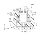
- 2 is an enlarged cross-sectional view showing a part of the configuration of the stator of the electric motor shown in FIG. 1;
- FIG. 4A to 4C are cross-sectional views showing other examples of the configuration of the stator according to Embodiment 1;
- FIG. 8A and 8B are cross-sectional views showing still another example of the configuration of the stator according to Embodiment 1;
- FIG. 5A is a cross-sectional view showing another example of the configuration of the resin portion shown in FIG. 4;
- FIG. 5(B) to (E) are cross-sectional views showing still another example of the configuration of the resin portion shown in FIG. 4.
- FIG. FIG. 4 is a cross-sectional view schematically showing a configuration of an electric motor according to a modification of Embodiment 1;
- FIG. 6 is a cross-sectional view schematically showing a part of the configuration of an electric motor according to Embodiment 2; 8A is a partial cross-sectional view schematically showing the configuration of a rotor of an electric motor according to Embodiment 3; FIG. (B) is a partial cross-sectional view schematically showing the configuration of the rotor of the electric motor according to the comparative example.
- FIG. 11 is a perspective view showing the configuration of a stator according to Embodiment 4;
- FIG. 12 is a perspective view showing the configuration of the stator core and insulator shown in FIG. 11; 12A is a plan view showing the configuration of the magnetic flux take-in member shown in FIG. 11;
- FIG. 11 is a perspective view showing the configuration of a stator according to Embodiment 4;
- FIG. 10B to 11D are plan views showing other examples of the configuration of the magnetic flux take-in member of the fourth embodiment
- FIG. 14A is a plan view showing a configuration of a magnetic flux take-in member of a stator according to Modification 1 of Embodiment 4
- FIG. 12B is a plan view showing another example of the configuration of the magnetic flux taking-in member of Modification 1 of Embodiment 4
- FIG. 11 is a plan view showing the configuration of a magnetic flux taking-in member of a stator according to Modification 2 of Embodiment 4;
- the z-axis is the coordinate axis parallel to the axis of the rotor shaft of the motor.
- the x-axis is a coordinate axis orthogonal to the z-axis.
- the y-axis is a coordinate axis orthogonal to both the x-axis and the z-axis.
- FIG. 1 is a partial cross-sectional view schematically showing the configuration of blower 150 according to Embodiment 1.
- blower 150 has electric motor 100 and impeller (also called “blade” or “fan”) 110 .
- Impeller 110 is driven by electric motor 100 to generate airflow.
- the electric motor 100 has a stator 1 and a rotor 2 . Note that the configuration of the stator 1 will be described later.
- the rotor 2 has a shaft 21 as a rotating shaft, a permanent magnet 22 as a rotor body, a first bearing 23 and a second bearing 24 .
- the rotor 2 is rotatable around the axis A of the shaft 21 .
- the shaft 21 protrudes from the stator 1 toward the +z-axis.
- the direction along the circumference of the circle centered on the axis A of the shaft 21 is called “circumferential direction C”.
- the z-axis direction is also called “axial direction”
- the direction perpendicular to the axial direction is called “radial direction”.
- the protruding side of the shaft 21 ie +z-axis side
- the side opposite to the load side of the shaft 21 ie -z-axis side
- anti-load side the protruding side of the shaft 21
- the permanent magnets 22 are arranged inside the stator 1 .
- a permanent magnet 22 is attached to the shaft 21 .
- the permanent magnet 22 is a cylindrical magnet elongated in the z-axis direction.
- N poles and S poles are alternately formed on the outer peripheral surface 22 a of the permanent magnet 22 .
- the rotor main body of the rotor 2 may be composed of a rotor core fixed to the shaft 21 and permanent magnets attached to the rotor core.
- the first bearing 23 is a bearing that supports the load side of the shaft 21.
- a first bearing 23 is held by the metal bracket 3 .
- the second bearing 24 is a bearing that supports the non-load side of the shaft 21 .
- the second bearing 24 is held by a later-described bearing holding portion 72 provided in the stator 1 .
- Each of the first bearing 23 and the second bearing 24 is a rolling bearing.
- the stator 1 has a stator core 10 , windings 20 , magnetic flux taking-in members 31 and 32 and a resin portion 50 .
- FIG. 2 is a perspective view showing part of the configuration of the stator 1 of the electric motor 100 shown in FIG.
- stator core 10 has yoke 11 extending in circumferential direction C and a plurality of teeth 12 .
- a plurality of teeth 12 are arranged in the circumferential direction C at predetermined intervals.
- the plurality of teeth 12 are radially opposed to the rotor 2 (see FIG. 1).
- Each tooth 12 of the plurality of teeth 12 has a tooth body portion 12a and a tooth tip portion 12b.
- the tooth body portion 12 a extends radially inward from the yoke 11 .
- the tooth tip portion 12b is arranged radially inward of the tooth body portion 12a and is wider in the circumferential direction C than the tooth body portion 12a.
- the stator core 10 has a first end face (specifically, an end face facing the +z-axis direction) 10a that is one end face in the axial direction, and a second end face that is the other end face. and an end face (specifically, an end face facing the -z-axis direction) 10b.
- the permanent magnet 22 described above has a third end face (specifically, an end face facing the +z-axis direction) 22a that is one end face in the axial direction, and a fourth end face (specifically, has an end surface 22b facing the -z-axis direction.
- L1 is the first length (hereinafter also referred to as “axial length”) that is the length of the stator core 10 in the z-axis direction
- L2 is the second length that is the length of the permanent magnet 22 in the z-axis direction.
- the length L1 is shorter than the length L2. That is, the length L1 and the length L2 satisfy the following formula (1).
- the stator core 10 has a plurality of electromagnetic steel sheets (not shown) laminated in the z-axis direction. Since the length L1 is shorter than the length L2, the number of magnetic steel sheets provided in the stator core 10 is reduced, so the cost of the stator core 10 can be reduced. Therefore, the cost of electric motor 100 can be reduced.
- the first end face 10a and the second end face 10b of the stator core 10 are arranged between the third end face 22c and the fourth end face 22d of the permanent magnet 22. At least one of the first end face 10a and the second end face 10b may be arranged between the third end face 22c and the fourth end face 22d of the permanent magnet 22.
- the second end face 10b of the stator core 10 may be located axially outside the fourth end face 22d of the permanent magnet 22 .
- the length L1 of the stator core 10 in the z-axis direction is shorter than the length L2 of the permanent magnets 22 in the z-axis direction.
- the length of the stator core in the z-axis direction is shorter than the length of the rotor body (permanent magnets 22 in the first embodiment) in the z-axis direction, It becomes difficult for the magnetic flux generated at the ends in the z-axis direction (hereinafter also referred to as “overhang portions”) not facing to the stator core and the windings.
- the output and efficiency of the motor may be reduced.
- the stator 1 has the magnetic flux taking-in members 31 and 32 made of magnetic material for taking in the magnetic flux of the permanent magnets 22 . This makes it easier for the magnetic flux generated at the overhanging portion of the permanent magnet 22 to flow through the stator core 10 and the windings 20 via the magnetic flux taking-in members 31 and 32 . Therefore, according to Embodiment 1, it is possible to reduce the cost of the electric motor 100 and prevent a decrease in the output and efficiency of the electric motor 100 . Therefore, in the rotor 2 of the electric motor 100, even if an inexpensive magnet with a low magnetic force (for example, a ferrite magnet) is used as the permanent magnet 22, the magnetic flux capturing members 31 and 32 absorb the magnetic flux of the magnet.
- an inexpensive magnet with a low magnetic force for example, a ferrite magnet
- the magnetic flux taking-in members 31 and 32 are, for example, metal pieces made of metal. Specifically, the magnetic flux taking-in members 31 and 32 are iron pieces made of iron.
- the plurality of magnetic flux taking-in members 31 and 32 are spaced apart from each other in the circumferential direction C. Specifically, the magnetic flux taking member 31 is arranged on the end face 12c of the tooth 12 facing the +z-axis direction, and the magnetic flux taking member 32 is arranged on the end face 12d of the tooth 12 facing the -z-axis direction. Note that the stator 1 can be realized without the magnetic flux taking-in member 32, as shown in FIG. 8, which will be described later.
- the magnetic flux taking-in members 31 and 32 are arranged at the tooth tip portions 12 b of the teeth 12 .
- the magnetic flux capturing members 31 and 32 are arranged closer to the permanent magnet 22 (see FIG. 1) than the configuration in which the magnetic flux capturing members 31 and 32 are disposed on the teeth main body 12a.
- the magnetic flux of the permanent magnet 22 is easily captured by the magnetic flux capturing members 31 and 32 .
- each of the magnetic flux taking-in members 31 and 32 when viewed in the z-axis direction is, for example, a curved shape (for example, an arc shape) having radially inward concave surfaces 31a and 32a.
- the shape of each of the magnetic flux taking-in members 31 and 32 when viewed in the z-axis direction may be rectangular.
- the magnetic flux taking-in members 31 and 32 may vibrate due to the magnetic force of the permanent magnet 22.
- the magnetic flux taking-in members 31 and 32 may vibrate in the circumferential direction C due to the magnetic force of the permanent magnet 22 while the electric motor 100 is rotating.
- a current is applied to the windings 20 (see FIG. 1) to generate magnetic attraction and repulsion between the rotor 2 and the stator 1, thereby rotating the electric motor 100.
- FIG. 1 The magnetic attraction force and repulsion force generated by such energization of the winding 20 also serve as a vibration source for the magnetic flux taking-in members 31 and 32 which are one of the constituent parts of the electric motor 100 . Therefore, it is necessary to suppress vibration of the magnetic flux receiving members 31 and 32 due to the magnetic force of the permanent magnet 22 or the magnetic force generated when the winding 20 is energized.
- the shaft 21 protrudes from the stator 1 in the +z-axis direction in order to transmit the rotational driving force of the electric motor 100 .
- the portion of the shaft 21 that protrudes from the permanent magnet 22 toward the load side (that is, the +z axis side), that is, the portion that includes the tip portion 21a that is the power transmission portion may be twisted to generate noise. be.
- the outer diameter D2 of the blade portion of the impeller 110 attached to the tip portion 21a of the shaft 21 is larger than the outer diameter D1 of the stator core 10.
- the impeller 110 since the impeller 110 has a large inertia, the projecting portion of the shaft 21 is likely to be twisted.
- the vibration component due to the torsion and bending of the shaft 21 resonates with the vibration component due to the magnetic force of the permanent magnet 22 and the like, the electric motor 100 generates a large noise.
- FIG. 3 is a cross-sectional view of a portion of the stator 1 shown in FIG. 1 cut along a curved surface extending in the circumferential direction C.
- the plurality of magnetic flux intake members 31 are denoted by 31u and 31v
- the plurality of magnetic flux acquisition members 32 by 32u and 32v
- the teeth 12 by 12u and 12v.
- the interval between the magnetic flux capturing members 31u and 31v adjacent in the circumferential direction C and the interval between the magnetic flux capturing members 32u and 32v adjacent in the circumferential direction C are collectively referred to as "first spacing. W1", and the interval between the teeth 12u, 12v adjacent to each other in the circumferential direction C is denoted as "second interval W2".
- the resin portion 50 fixes the plurality of magnetic flux taking-in members 31u, 31v, 32u, 32v to the plurality of teeth 12u, 12v, respectively.
- vibrations in the circumferential direction C of the magnetic flux intake members 31u, 31v, 32u, and 32v due to magnetic force such as the magnetic force of the permanent magnet 22 can be suppressed.
- the resin portion 50 surrounds the plurality of magnetic flux capturing members 30 so as to be fixed to the end surfaces 12c and 12d of the plurality of teeth 12 in the z-axis direction.
- the resin portion 50 fills the first gap W1. This makes it difficult for the magnetic flux taking-in members 31u, 31v, 32u, and 32v to move in the circumferential direction C. Vibration of the magnetic flux receiving members 31u, 31v, 32u, and 32v can be suppressed even when magnetic flux receiving members 31u, 31v, 32u, and 32v are acted on by magnetic flux receiving members 31u, 31v, 32u and 32v. Therefore, noise in the stator 1, in other words, noise in the electric motor 100 can be reduced.
- the resin portion 50 fills not only the first space W1, but also the second space W2 between the teeth 12u and 12v adjacent in the circumferential direction C. As a result, vibration of teeth 12u and 12v during rotation of electric motor 100 can be suppressed.
- the first spacing W1 is larger than the second spacing W2. That is, the first interval W1 and the second interval W2 satisfy the following formula (2). W1>W2 (2) Since the first gap W1 and the second gap W2 satisfy the expression (2), the amount of the resin portion 50 filling the first gap W1 increases. It is possible to more firmly fix to the end faces 12c and 12d of the z-axis direction of 12u and 12v. Therefore, it is possible to further suppress the magnetic flux taking-in members 31u, 31v, 32u, and 32v from vibrating due to the magnetic force generated between the rotor 2 and the stator 1. FIG. Therefore, noise in the stator 1 can be further reduced.
- the first spacing W1 should be larger than the second spacing W2 as shown in Equation (2). is preferred. Note that the first interval W1 may be the same as the second interval W2. That is, it is sufficient that the first interval W1 is equal to or greater than the second interval W2.
- the width in the circumferential direction C of the magnetic flux taking-in members 31 and 32 is narrower than the width in the circumferential direction C of the tooth tip portion 12b.
- the surface area (in other words, volume) of the magnetic flux receiving members 31 and 32 is reduced, so the amount of magnetic flux passing through the magnetic flux receiving members 31 and 32 is reduced. Therefore, since the magnetic force in the magnetic flux receiving members 31 and 32 is reduced, the vibration of the magnetic flux receiving members 31 and 32 can be further suppressed.
- the magnetic flux receiving members 31 and 32 are collectively referred to as the "magnetic flux receiving member 30".
- FIG. 4 is an enlarged sectional view showing a part of the configuration of stator 1 of electric motor 100 shown in FIG.
- the radial thickness of the magnetic flux take-in member 30 is a first thickness t1
- the radial thickness of the teeth 12 is a second thickness t2
- the first thickness t1 is the second thickness. 2 thickness t2. That is, the first thickness t1 and the second thickness t2 satisfy the following formula (3). t1 ⁇ t2 (3)
- the volume of the magnetic flux capturing member 30 is reduced, so the amount of magnetic flux passing through the magnetic flux capturing member 30 is reduced. Therefore, since the magnetic force acting on the magnetic flux capturing member 30 is reduced, vibration in the magnetic flux capturing member 30 can be suppressed. Therefore, noise generation in the stator 1 can be further reduced.
- the resin portion 50 has an insulator 60 and a molded resin portion 70. As shown in FIGS. 1, 3 and 4, the resin portion 50 has an insulator 60 and a molded resin portion 70. As shown in FIGS. 1, 3 and 4, the resin portion 50 has an insulator 60 and a molded resin portion 70. As shown in FIGS. 1, 3 and 4, the resin portion 50 has an insulator 60 and a molded resin portion 70. As shown in FIGS.
- the insulator 60 is an insulating member that insulates the windings 20 and the stator core 10 from each other.
- the insulator 60 is made of thermoplastic resin such as PPS (Poly Phenylene Sulfide) and PBT (Poly Butylene Terephthalate).
- the insulator 60 has a first insulating portion 61, a second insulating portion 62, and an extension portion 63 as a third insulating portion.
- the first insulating portion 61 is a portion of the insulator 60 that is provided radially inward of the windings 20 and covers the teeth 12 .
- the first insulating portion 61 covers the end surface 30a facing the +z-axis direction and the radially outward surface 30b of the magnetic flux capturing member 30 .
- the second insulating portion 62 is a portion of the insulator 60 that is provided radially outside the winding 20 and covers the yoke 11 .
- the extending portion 63 is a portion of the insulator 60 that connects the first insulating portion 61 and the second insulating portion 62 .
- the extending portion 63 extends radially outward from the ⁇ z-axis side end of the first insulating portion 61 . It should be noted that the insulator 60 can be realized without the second insulating portion 62, as shown in FIG. 7B, which will be described later.
- the third thickness t3 is thicker than the first thickness t1. That is, the first thickness t1 and the third thickness t3 satisfy the following formula (4). t3>t1 (4)
- the sound transmittance varies depending on the thickness of the sound-transmitting material. Therefore, the radial thickness (that is, the third thickness t3) of the resin portion 50 (for example, the insulator 60) filling the first space W1 shown in FIG. (that is, the first thickness t1), the vibration of the magnetic flux take-in member 30 can be further suppressed.
- the mold resin portion 70 is made of, for example, thermosetting resin.
- the mold resin portion 70 is molded by injection molding, for example. Also, the molded resin portion 70 is integrated with the stator core 10, the windings 20, the magnetic flux take-in member 30, and the insulator 60 by integral molding.
- the mold resin portion 70 covers the windings 20 .
- the molded resin portion 70 fixes the windings 20 to the stator core 10 . This suppresses the windings 20 from vibrating due to magnetic force or Lorentz force when energized, so noise in the stator 1 can be further reduced.
- the mold resin portion 70 has an opening portion 71, a bearing holding portion 72, and a fixing portion 73.
- a metal bracket 3 that supports the first bearing 23 on the load side is fixed to the opening 71 .
- the metal bracket 3 is fixed to the opening 71 by, for example, press fitting.
- the bearing holding portion 72 is a recess in which the second bearing 24 in the mold resin portion 70 is held.
- the circuit board 5 is embedded in the portion of the mold resin portion 70 on the ⁇ z-axis side of the bearing holding portion 72 .
- a power supply lead (not shown) for supplying power to the winding 20 is connected to the circuit board 5 .
- the circuit board 5 is fixed to the insulator 60 via the winding terminals 4 connected to the windings 20 .
- the fixed portion 73 is a portion of the electric motor 100 that is attached to a support portion of an object to be attached (for example, a motor support portion provided in an outdoor unit).
- the fixed portion 73 extends radially outward from the end portion of the mold resin portion 70 on the opposite side of the load.
- the fixed portion 73 has an insertion hole 73a through which a fastening member (for example, a bolt) is inserted.
- FIG. 5A the first center position, which is the center position of the magnetic flux taking-in members 31u and 31v in the circumferential direction C, is P1, and the second center position, which is the center position of the teeth 12u and 12v in the circumferential direction C. Let the position be P2. As shown in FIGS. 5A to 5C, the first center position P1 may be displaced from the second center position P2 in the circumferential direction C (see FIG. 2). As a result, the torque fluctuation of the electric motor 100 is suppressed by the skew effect, so noise can be further reduced.
- FIG. 6A and (B) are cross-sectional views showing still another example of the configuration of the stator 1 according to the first embodiment.
- the insulator 60 covers part of the side surface 30c of the magnetic flux capturing member 30 facing the circumferential direction C (see FIG. 2), and the molded resin portion 70 covers the magnetic flux capturing member 30. may cover the end face 30a facing the +z-axis direction and part of the side face 30c. That is, the insulator 60 can be realized without covering the end face 30a of the magnetic flux taking-in member 30 facing the +z-axis direction.
- insulator 60 can be miniaturized as compared with the configuration shown in FIG. Therefore, since the amount of thermoplastic resin, which is more expensive than thermosetting resin, is reduced, the cost of electric motor 100 can be further reduced.
- the insulator 60 partially covers the end surface 30a of the magnetic flux capturing member 30 facing the +z-axis direction, and the molded resin portion 70 covers the end surface 30a and the magnetic flux capturing member 30. It covers the side surface 30c facing the circumferential direction C (see FIG. 2). That is, the insulator 60 can be realized without covering the side surface 30c of the magnetic flux taking-in member 30 facing the circumferential direction C. As a result, the amount of expensive thermoplastic resin is reduced compared to the configuration shown in FIG. 3, so the cost of electric motor 100 can be further reduced.
- FIGS. 7(A) to 7(E) Next, another example of the shape of the insulator 60 of the resin portion 50 will be described with reference to FIGS. 7(A) to 7(E). Note that the windings 20 are omitted from FIGS. 7A to 7E.
- FIG. 7(A) is a cross-sectional view showing another example of the configuration of the resin portion 50 shown in FIG.
- the insulator 60 partially covers the radially outward surface 30b of the magnetic flux capturing member 30, and the mold resin portion 70 extends along the +z-axis direction of the magnetic flux capturing member 30. It covers the facing end face 30a. That is, the insulator 60 can be realized without covering the end surface 30a of the magnetic flux taking-in member 30 facing the +z-axis direction.
- the insulator 60 includes a first insulating portion 61 and an extending portion 63 extending radially outward from the end of the first insulating portion 61 on the stator core 10 side. have. That is, the insulator 60 can be realized without the second insulating portion 62 shown in FIG.
- both the insulator 60 and the mold resin portion 70 may cover the end face 30a of the magnetic flux take-in member 30 facing the +z-axis direction.
- the mold resin portion 70 may cover the radially outward surface 30b of the magnetic flux intake member 30 and the end surface 30a facing the +z-axis direction.
- the insulator 60 is arranged radially with a gap from the radially outward surface 30b of the magnetic flux take-in member 30, and the mold resin portion 70 fills the gap. It is Thereby, insulator 60 can be miniaturized.
- the magnetic flux taking-in member 30 may be arranged on the end surface of the stator core 10 facing the +z-axis direction with the resin portion 50 (here, the insulator 60) sandwiched therebetween.
- the windings 20 are wound around the teeth 12 of the stator core 10 .
- the windings 20 are, for example, aluminum wires that are cheaper than copper wires. Therefore, the cost of electric motor 100 can be reduced.
- the axial length of stator core 10 ie, length L1
- the axial length of permanent magnet 22 ie, length L2
- the resistance of the winding 20 is also reduced.
- the tensile strength of aluminum wire is lower than that of copper wire. Therefore, when the windings 20 are made of aluminum wire, the tensile strength of the windings 20 during the work of winding the windings 20 around the stator core 10 is low, and the fixing force of the windings 20 to the stator core 10 is small. In this case, the winding 20 tends to vibrate when a current is applied to the winding 20 .
- resin portion 50 specifically, molded resin portion 70 covers winding 20. As shown in FIG. As a result, even when a current is applied to the winding 20 made of aluminum wire, the vibration of the winding 20 can be suppressed.
- the windings 20 are aluminum wires and the windings 20 are covered with the molded resin portion 70, thereby further reducing the cost of the stator 1 and further reducing the noise in the stator 1. can be done.
- the winding 20 may be an aluminum alloy wire having a higher tensile strength than the aluminum wire.
- first bearing 23 and the second bearing 24 are slide bearings, there is a gap between the slide bearings and the outer peripheral surface of the shaft 21 . Therefore, while the electric motor 100 is rotating, the shaft 21 is likely to move in the radial direction, and the air gap between the permanent magnet 22 and the stator 1 is likely to change. Therefore, when the first bearing 23 and the second bearing 24 are slide bearings, the size of the air gap between the permanent magnet 22 and the stator 1 becomes unbalanced in the axial direction when the electric motor 100 rotates. This makes it easier for the magnetic flux taking-in member 30 to vibrate.
- the first bearing 23 and the second bearing 24 that support the shaft 21 are rolling bearings.
- the first bearing 23 and the second bearing 24 have an inner ring press-fitted onto the shaft 21, an outer ring fixed to the bearing holder, and rolling elements arranged between the inner ring and the outer ring. .
- the length L1 of the stator core 10 in the z-axis direction is shorter than the length L2 of the permanent magnets 22 in the z-axis direction.
- the number of magnetic steel sheets used for the stator core 10 is reduced, so the cost of the stator 1 can be reduced. Therefore, the cost of electric motor 100 can be reduced.
- the stator 1 has the magnetic flux take-in member 30 made of a magnetic material that takes in the magnetic flux of the permanent magnets 22 .
- the magnetic flux generated at the overhang portion of the permanent magnet 22 flows through the stator core 10 and the windings 20 via the magnetic flux taking-in member 30 . Therefore, a decrease in the amount of magnetic flux flowing from the permanent magnets 22 to the stator 1 can be suppressed. Therefore, a decrease in the output and efficiency of the electric motor 100 can be suppressed.
- the resin portion 50 fills the first space W1 between the magnetic flux capturing members 30 adjacent in the circumferential direction C among the plurality of magnetic flux capturing members 30.
- This makes it difficult for the magnetic flux taking-in member 30 to move in the circumferential direction C.
- the magnetic force described above for example, the magnetic force of the permanent magnet 22 and the magnetic force generated when the winding 20 is energized
- the magnetic flux capturing Vibration of the member 30 can be suppressed. Therefore, noise in the stator 1 can be reduced.
- the electric motor 100 it is possible to reduce noise while reducing cost and suppressing a decrease in output and efficiency.
- the first spacing W1 between the magnetic flux taking-in members 30 adjacent in the circumferential direction C is longer than the second spacing W2 between the teeth 12 adjacent in the circumferential direction C. Accordingly, it is possible to suppress vibration of the magnetic flux capturing members 30 due to the magnetic force acting between the magnetic flux capturing members 30 adjacent in the circumferential direction C. Therefore, noise in the stator 1 can be further reduced.
- the radial thickness of the magnetic flux taking-in member 30 is thinner than the radial thickness of the teeth 12 .
- the volume of the magnetic flux capturing member 30 is reduced, so the amount of magnetic flux passing through the magnetic flux capturing member 30 is reduced. Therefore, since the magnetic force acting on the magnetic flux capturing member 30 is reduced, vibration in the magnetic flux capturing member 30 can be suppressed. Therefore, noise in the stator 1 can be further reduced.
- the radial thickness of the resin portion 50 filling the first gap W1 is greater than the radial thickness of the magnetic flux taking member 30 .
- the width in the circumferential direction C of the magnetic flux taking-in member 30 is narrower than the width in the circumferential direction C of the teeth 12 .
- the surface area (in other words, volume) of the magnetic flux capturing member 30 is reduced, so the amount of magnetic flux passing through the magnetic flux capturing member 30 is reduced. Therefore, since the magnetic force in the magnetic flux receiving member 30 is reduced, the vibration of the magnetic flux receiving member 30 is further suppressed, and the noise in the stator 1 can be further reduced.
- the resin portion 50 covers the end surface 30a of the magnetic flux taking member 30 facing the +z-axis direction and the radially outward surface 30b.
- the magnetic flux taking-in member 30 can be fixed to the teeth 12 more firmly. Therefore, vibration of the magnetic flux taking-in member 30 due to magnetic force is suppressed, and noise in the stator 1 can be further reduced.
- the first bearing 23 and the second bearing 24 that support the shaft 21 are rolling bearings.
- the air gap between the rotor 2 and the stator 1 is less likely to change during the rotation of the electric motor 100 compared to a structure in which the first bearing 23 and the second bearing 24 are sliding bearings. Therefore, the vibration of the magnetic flux taking-in member 30 is further suppressed, and the noise in the stator 1 can be further reduced.
- FIG. 8 is a cross-sectional view showing a schematic configuration of an electric motor 100A according to a modification of the first embodiment. 8, the same or corresponding components as those shown in FIG. 1 are given the same reference numerals as those shown in FIG.
- the stator 1A of the electric motor 100A according to the modification of the first embodiment differs from the stator 1 of the electric motor 100 according to the first embodiment in that the magnetic flux intake member 32 is not provided.
- Electric motor 100A according to the modification of Embodiment 1 is the same as electric motor 100 according to Embodiment 1 except for this point. 1 and 2 are therefore referred to in the following description.
- the electric motor 100A has a stator 1A and a rotor 2.
- the stator 1A has a stator core 10, windings 20, a magnetic flux take-in member 31A, and a resin portion 50.
- the magnetic flux receiving member 31A is the only magnetic flux receiving member provided in the stator 1A. This reduces the number of parts in the electric motor 100A and simplifies the assembly process of the electric motor 100A.
- the stator core 10 is arranged on the anti-load side (that is, the second bearing 24 side) of the central portion of the permanent magnet 22 in the z-axis direction.
- the length of the magnetic flux taking-in member 31A in the z-axis direction is longer than the length L1 of the stator core 10 in the z-axis direction (see FIG. 1).
- the magnetic flux receiving member 31A is the only magnetic flux receiving member provided in the stator 1A of the electric motor 100A. As a result, the number of parts constituting the electric motor 100A can be reduced, and the assembling process of the electric motor 100A can be simplified.
- FIG. 9 is a cross-sectional view schematically showing part of the configuration of electric motor 200 according to the second embodiment.
- the same or corresponding components as those shown in FIG. 1 are given the same reference numerals as those shown in FIG.
- Electric motor 200 according to Embodiment 2 differs from electric motor 100 according to Embodiment 1 in the configuration of stator 201 .
- Electric motor 200 according to the second embodiment is the same as electric motor 100 according to the first embodiment except for this point. Therefore, FIG. 2 will be referred to in the following description.
- the electric motor 200 has a stator 201 and a rotor 2 .
- the stator 201 has a stator core 10 , windings 20 , magnetic flux take-in members 230 and a resin portion 50 .
- the magnetic flux taking-in member 230 takes in the magnetic flux from the permanent magnet 22 .
- the magnetic flux take-in members 230 are arranged on the axial end surfaces of the teeth 12 (see FIG. 2) of the stator core 10 .
- a surface of the magnetic flux capturing member 230 facing the permanent magnet 22 that is, a radially inward surface 230 d is positioned radially outside the inner peripheral surface 10 c of the stator core 10 .
- the distance between the outer peripheral surface 22a of the permanent magnet 22 and the inner peripheral surface 10c of the stator core 10 is the first air gap E1
- the radial direction of the outer peripheral surface 22a of the permanent magnet 22 and the magnetic flux taking-in member 230 is and the inward surface 230d of the second air gap E2.
- the second air gap E2 is larger than the first air gap E1. That is, the first air gap E1 and the second air gap E2 satisfy the following formula (5).
- E1>E2 (5) As a result, the magnetic flux capturing member 230 is less likely to be affected by the magnetic force of the permanent magnet 22, so that vibration of the magnetic flux capturing member 230 due to the magnetic force can be suppressed. Therefore, noise in stator 201 can be reduced.
- the resin portion 50 fixes the magnetic flux taking-in member 230 to the stator core 10 .
- the molded resin portion 70 of the resin portion 50 is in contact with the radially inward surface 230 d of the magnetic flux take-in member 230 .
- the area of the resin portion 50 in contact with the magnetic flux capturing member 230 is increased, so that the fixing strength of the magnetic flux capturing member 230 to the stator core 10 is further increased. Therefore, the vibration of the magnetic flux taking-in member 230 can be further suppressed.
- the insulator 60 may be in contact with the radially inward surface 230 d of the magnetic flux take-in member 230 .
- t30 is the radial thickness of the portion of the mold resin portion 70 located radially inward of the magnetic flux taking-in member 230 .
- the thickness t30 corresponds to a value obtained by subtracting the first air gap E1 from the second air gap E2.
- thickness t30 is thinner than the radial thickness of a portion (for example, insulator 60) of resin portion 50 located radially outside magnetic flux taking-in member 230. As shown in FIG. As a result, it is possible to prevent the output and efficiency of the electric motor 200 from being lowered. Therefore, in the second embodiment, it is possible to prevent the output and efficiency of the electric motor 200 from decreasing while suppressing the vibration of the magnetic flux taking-in member 230 .
- the second air gap E2 between the outer peripheral surface 22a of the permanent magnet 22 and the radially inward surface 230d of the magnetic flux taking-in member 230 It is larger than the first air gap E1 between the outer peripheral surface 230a and the inner peripheral surface 10c of the stator core 10.
- the magnetic flux capturing member 230 is less likely to be affected by the magnetic force of the permanent magnet 22, so that vibration of the magnetic flux capturing member 230 due to the magnetic force can be suppressed. Therefore, the noise in stator 201, that is, the noise in electric motor 200 can be reduced.
- the thickness t30 of the molded resin portion 70 disposed radially inside the magnetic flux capturing member 230 in the resin portion 50 is greater than the magnetic flux capturing member 230 of the resin portion 50 in the radial direction. thinner than the radial thickness of the portion located outside the As a result, it is possible to prevent a decrease in the output and efficiency of the electric motor 200 while reducing noise.
- FIG. 10A is a partial cross-sectional view showing the configuration of rotor 302 of the electric motor according to Embodiment 3.
- FIG. 10(A) the same reference numerals as those shown in FIG. 1 are attached to the constituent elements that are the same as or correspond to those shown in FIG.
- the electric motor according to the third embodiment is similar to the first embodiment in terms of the relationship between the distance between the first bearing 23 and the second bearing 24 and the axial length of the permanent magnet 322. It is different from the electric motor 100 according to Otherwise, electric motor 300 according to the third embodiment is the same as electric motor 100 according to the first embodiment. Therefore, FIG. 1 will be referred to in the following description.
- the rotor 302 has a shaft 21, permanent magnets 322, a first bearing 23 and a second bearing 24.
- the permanent magnet 322 is attached to the shaft 21.
- the permanent magnet 322 has a first recess 322e provided on the end face 322c facing the +z-axis direction and a second recess 322f provided on the end face 322d facing the -z-axis direction.
- FIG. 10B is a partial cross-sectional view showing the configuration of the rotor 302A of the electric motor according to the comparative example.
- distance L30 between first bearing 23 supporting the load side of shaft 21 and second bearing 24 supporting the anti-load side of shaft 21 is shorter than length L2.
- the force acting on the first bearing 23 on the load side increases during rotation of the electric motor, so the first bearing 23 is likely to wear out.
- the bearing wear is the wear of the inner ring and the outer ring of the first bearing 23 .
- the distance L3 between the first bearing 23 on the load side and the second bearing 24 on the anti-load side is equal to It is longer than or equal to L2. This reduces the force acting on the first bearing 23 and the second bearing 24 during rotation of the electric motor according to the third embodiment. Therefore, since wear of the first bearing 23 and the second bearing 24 is suppressed, it becomes difficult for the shaft 21 to move radially during rotation of the electric motor. Therefore, between the magnetic flux flowing from the rotor 302 to the +z-axis side magnetic flux capturing member 31 (see FIG. 1) and the magnetic flux flowing from the rotor 302 to the -z-axis side magnetic flux capturing member 32 (see FIG. 1) magnetic unbalance can be reduced, and the vibration due to the magnetic unbalance can be further suppressed.
- the distance L3 between the first bearing 23 on the load side of the shaft 21 and the second bearing 24 on the anti-load side is the length of the permanent magnet 322 in the axial direction. L2 or higher. Thereby, the noise in the electric motor according to Embodiment 3 can be further reduced.
- FIG. 11 is a perspective view showing the configuration of stator 401 of the electric motor according to Embodiment 4.
- FIG. 12 is a perspective view showing the configuration of stator core 10 and insulator 460 shown in FIG. 11 and 12, the same or corresponding components as those shown in FIG. 1 are given the same reference numerals as those shown in FIG.
- the electric motor according to Embodiment 4 differs from electric motor 100 according to Embodiment 1 in the shape of magnetic flux taking-in member 430 of stator 401 . Except for this point, the electric motor according to the fourth embodiment is the same as the electric motor 100 according to the first embodiment. Therefore, FIG. 1 will be referred to in the following description.
- the stator 401 has a stator core 10, windings 20 (see FIG. 1), a magnetic flux taking-in member 430, and a resin portion 450.
- the magnetic flux take-in member 430 takes in magnetic flux from the rotor 2 .
- the magnetic flux take-in members 430 are arranged on the end surfaces 12c and 12d of the teeth 12 of the stator core 10 in the z-axis direction.
- the magnetic flux take-in member 430 has a radially inward concave surface 431a.
- the shape of the magnetic flux take-in member 430 when viewed in the z-axis direction is, for example, an arc shape. This increases the contact area between the stator core 10 and the magnetic flux capturing member 430 compared to a configuration in which the magnetic flux capturing member has a rectangular shape when viewed in the z-axis direction.
- the fixing strength of the member 430 can be improved.
- the resin portion 450 has an insulator 460 that insulates the stator core 10 from the windings, and a mold resin portion (not shown).
- the insulator 460 has a first insulating portion 461 that insulates the tooth 12 and the winding 20 from each other.
- Magnetic flux take-in member 430 is in contact with first insulating portion 461 of insulator 460 . This facilitates positioning of the magnetic flux take-in member 430 .
- FIG. 13(A) is a plan view showing the configuration of the magnetic flux taking-in member 430 shown in FIG. As shown in FIG. 13A, the magnetic flux take-in member 430 has a plurality of projections 441 provided on a radially outward surface 431b.
- the convex portion 441 extends from both ends in the circumferential direction C of the radially outward surface 431b in a direction away from the permanent magnet 22 (see FIG. 1) (that is, in a radial direction). outward). Further, in the example shown in FIG. 13A, the convex portion 441 protrudes radially outward so that the magnetic flux take-in member 430 becomes wider in the circumferential direction C. As shown in FIG. As a result, even if magnetic attraction is generated between the permanent magnet 22 and the magnetic flux receiving member 430 during rotation, the magnetic flux receiving member 430 is less likely to come off. Therefore, the reliability of the electric motor can be improved.
- the width W3 of the magnetic flux take-in member 430 in the circumferential direction C is W3, and the width W4 of the tooth tip 12b in the circumferential direction C is W4 in FIG. . That is, the width W3 and the width W4 satisfy the following formula (7). W3 ⁇ W4 (7) Thereby, interference between two magnetic flux intake members 430 adjacent in the circumferential direction C can be prevented.
- the convex portion 441 is fitted into a concave portion 461a provided on the radially inward surface of the insulator 460.
- the fixing strength of the magnetic flux taking-in member 430 is improved. Therefore, even when a magnetic force (for example, the magnetic force of the permanent magnet 22 and the magnetic force generated when the winding 20 is energized) acts on the magnetic flux capturing member 430, the magnetic flux capturing member 430 vibration can be suppressed. Therefore, noise in the stator can be reduced.
- a magnetic force for example, the magnetic force of the permanent magnet 22 and the magnetic force generated when the winding 20 is energized
- FIGS. 13(B) to 13(D) are plan views showing other examples of the configuration of the magnetic flux taking-in member 430 according to the fourth embodiment.
- the protrusions 441 can be realized even if they do not protrude radially outward from both ends in the circumferential direction C of the magnetic flux taking-in member 430 .
- the projection 441 may protrude radially outward from one end in the circumferential direction C of the radially outward surface 431b.
- the magnetic flux capturing member 430 can be realized without the protrusion 441, and the radial thickness t4 of the magnetic flux capturing member 430 is reduced in the circumferential direction. C may be uniform.
- the convex portion 441 may be provided at the center portion in the circumferential direction C of the radially outward surface 431b of the magnetic flux take-in member 430 . Thereby, interference between the convex portion 441 and another magnetic flux taking-in member 430 adjacent in the circumferential direction C can be prevented.
- magnetic flux capturing member 430 has radially inward concave surface 431a.
- the shape of the magnetic flux take-in member 430 when viewed in the z-axis direction is, for example, an arc shape. This increases the contact area between the stator core 10 and the magnetic flux capturing member 430 compared to a configuration in which the magnetic flux capturing member has a rectangular shape when viewed in the z-axis direction.
- the fixing strength of the member 430 can be improved.
- the magnetic flux taking-in member 430 has the protrusion 441 provided on the radially outward surface 431b.
- the contact area between the stator core 10 and the magnetic flux receiving member 430 is further increased, so that the fixing strength of the magnetic flux receiving member 430 can be further improved.
- the positioning of the magnetic flux capturing member 430 when fixing the magnetic flux capturing member 430 to the insulator 460 can be facilitated.
- the convex portion 441 protrudes radially outward from the radially outward surface 431 b of the magnetic flux taking member 430 , and the convex portion 441 extends in the radial direction of the insulator 460 . It fits into a recess 461a provided on the inward surface. Thereby, the fixing strength of the magnetic flux taking-in member 430 is improved. Therefore, even when a magnetic force (for example, the magnetic force of the permanent magnet 22 and the magnetic force generated when the winding 20 is energized) acts on the magnetic flux capturing member 430, the magnetic flux capturing member 430 vibration can be suppressed. Therefore, noise in the stator can be reduced.
- a magnetic force for example, the magnetic force of the permanent magnet 22 and the magnetic force generated when the winding 20 is energized
- FIG. 14A is a plan view showing the configuration of a magnetic flux take-in member 430A of a stator according to Modification 1 of Embodiment 4.
- FIG. 14(A) the same or corresponding components as those shown in FIG. 13(A) are given the same reference numerals as those shown in FIG. 13(A).
- the stator according to Modification 1 of Embodiment 4 differs from stator 401 according to Embodiment 4 in the shape of magnetic flux taking-in member 430A. Except for this point, the stator according to the first modification of the fourth embodiment is the same as the stator according to the fourth embodiment. Therefore, FIG. 11 and the like will be referred to in the following description.
- the magnetic flux take-in member 430A has a plurality of protrusions 441A provided at both ends in the circumferential direction C of the radially outward surface 431b.
- the convex portion 441A protrudes from the end portion in the circumferential direction C of the radially outward surface 431b so that the width W31 in the circumferential direction C of the magnetic flux intake member 430A is constant.
- the width W31 in the circumferential direction C of the magnetic flux taking-in member 430 can be increased to the width W4 in the circumferential direction C of the tip end portion 12b of the tooth 12 .
- the magnetic flux take-in member 430A can easily take in the magnetic flux generated at the overhang portion of the permanent magnet 22 (see FIG. 1).
- the width W31 in the circumferential direction C of the magnetic flux intake member 430A is the shortest distance between the side surfaces 442 on both sides in the circumferential direction C of the magnetic flux intake member 430A.
- FIG. 14(B) is a plan view showing another example of the configuration of the magnetic flux take-in member 430A of the stator according to Modification 1 of Embodiment 4.
- FIG. 14B the convex portion 441A of the magnetic flux take-in member 430A extends radially inward toward the permanent magnet 22 (see FIG. 1) from the radially inward concave surface 431a. may protrude into
- an insulator or a mold resin portion covers the concave surface 431a, so that the magnetic field generated between the rotor 2 (see FIG. 1) and the stator 401 (see FIG. 11) is reduced. It is possible to prevent the magnetic flux take-in member 430A from falling off due to force.
- the convex portion 441A has a radially outward surface 431b or a radially outward surface 431b so that the width W31 in the circumferential direction C of the magnetic flux intake member 430A is constant. direction inward concave surface 431a.
- the width W3 in the circumferential direction C of the magnetic flux take-in member 430A can be increased to the width W2 in the circumferential direction C of the tip end portion 12b of the tooth 12.
- FIG. Therefore, the magnetic flux take-in member 430A can easily take in the magnetic flux generated at the overhang portion of the permanent magnet 22 .
- FIG. 15 is a plan view showing the configuration of a magnetic flux take-in member 430B of a stator according to Modification 2 of Embodiment 4.
- the same reference numerals as those shown in FIG. 13(A) are attached to the constituent elements that are the same as or correspond to the constituent elements shown in FIG. 13(A).
- the stator according to Modification 2 of Embodiment 4 differs from the stator according to Embodiment 4 in the shape of magnetic flux taking-in member 430B. Except for this point, the stator according to the second modification of the fourth embodiment is the same as the stator according to the fourth embodiment. Therefore, FIG. 11 and the like will be referred to in the following description.
- the magnetic flux take-in member 430B has a projection 441B provided on a radially outward surface 431b.
- the convex portion 441B protrudes radially outward from the center portion in the circumferential direction C of the radially outward surface 431b.
- the convex portion 441B becomes wider as it moves away from the radially outward surface 431b.
- a side surface 443 facing the circumferential direction C of the convex portion 441B extends while being inclined in the circumferential direction C so that the convex portion 441B becomes wider the further it is away from the radially outward surface 431b.
Landscapes
- Engineering & Computer Science (AREA)
- Power Engineering (AREA)
- Iron Core Of Rotating Electric Machines (AREA)
Abstract
Description
図1は、実施の形態1に係る送風機150の構成を概略的に示す部分断面図である。図1に示されるように、送風機150は、電動機100と、羽根車(「翼」又は「ファン」とも呼ぶ。)110とを有する。羽根車110は、電動機100によって駆動されることにより、気流を生成する。
電動機100は、固定子1と、回転子2とを有する。なお、固定子1の構成については、後述する。
次に、固定子1の構成について説明する。固定子1は、固定子鉄心10と、巻線20と、磁束取込部材31、32と、樹脂部50とを有する。
L1<L2 (1)
ここで、固定子鉄心10は、z軸方向に積層された複数の電磁鋼板(図示しない)を有する。長さL1が長さL2より短いことによって、固定子鉄心10に備えられる電磁鋼板の数が少なくなるため、固定子鉄心10のコストを低減することができる。よって、電動機100のコストを低減することができる。
W1>W2 (2)
第1の間隔W1及び第2の間隔W2が式(2)を満たすことにより、第1の間隔W1を埋める樹脂部50の量が増えるため、磁束取込部材31u、31v、32u、32vをティース12u、12vのz軸方向の端面12c、12dに一層強固に固定することができる。よって、回転子2と固定子1との間に発生する磁気的な力によって、磁束取込部材31u、31v、32u、32vが振動することを一層抑制することができる。したがって、固定子1における騒音を一層低減することができる。また、磁束取込部材31u、31v、32u、32vは、ティース12u、12vより振動し易いため、式(2)に示されるように、第1の間隔W1を第2の間隔W2より大きくすることが好ましい。なお、第1の間隔W1は、第2の間隔W2と同じであってもよい。すなわち、第1の間隔W1は、第2の間隔W2以上であればよい。
t1<t2 (3)
これにより、磁束取込部材30の体積が小さくなるため、当該磁束取込部材30を通過する磁束の磁束量が少なくなる。よって、磁束取込部材30に作用する磁気的な力が小さくなるため、磁束取込部材30における振動を抑えることができる。よって、固定子1における騒音の発生を一層低減することができる。
t3>t1 (4)
一般的に、音の透過率は、音が透過する物質の厚みで変化する。そのため、上述した図3に示される第1の間隔W1を埋めている樹脂部50(例えば、インシュレータ60)の径方向の厚み(すなわち、第3の厚みt3)を磁束取込部材30の径方向の厚み(すなわち、第1の厚みt1)より厚くすることによって、磁束取込部材30の振動を一層抑制することができる。
図5(A)から(C)は、実施の形態1に係る固定子1の構成の他の例を示す断面図である。図5(A)において、磁束取込部材31u、31vの周方向Cの中心の位置である第1の中心位置をP1、ティース12u、12vの周方向Cの中心の位置である第2の中心位置をP2とする。図5(A)から(C)に示されるように、第1の中心位置P1は、第2の中心位置P2に対して周方向C(図2参照)にずれて配置されていてもよい。これにより、スキュー効果によって、電動機100のトルク変動が抑制されるため、騒音を一層低減することができる。
次に、図1に戻って巻線20の構成について説明する。巻線20は、固定子鉄心10のティース12に巻き付けられている。巻線20は、例えば、銅線より安価なアルミ線である。よって、電動機100のコストを低減することができる。上述した通り、電動機100では、固定子鉄心10の軸長(すなわち、長さL1)は、永久磁石22の軸長(すなわち、長さL2)より短い。この場合、巻線20の周長も短くなるため、巻線20の抵抗値も小さくなる。これにより、銅線より導電率の低いアルミ線が巻線20に適用された場合であっても、抵抗値の上昇を抑制しつつ、電動機100のコストを低減することができる。
次に、第1の軸受23及び第2の軸受24の構成について説明する。仮に、第1の軸受23及び第2の軸受24が滑り軸受である場合、当該滑り軸受とシャフト21の外周面との間には隙間が生じている。そのため、電動機100の回転中において、シャフト21が径方向に動き易く、永久磁石22と固定子1との間のエアギャップが変化し易い。よって、第1の軸受23及び第2の軸受24が滑り軸受である場合、電動機100の回転時に、永久磁石22と固定子1との間のエアギャップの大きさが軸方向においてアンバランスになり易く、磁束取込部材30の振動が発生し易くなる。
以上に説明した実施の形態1によれば、固定子鉄心10のz軸方向の長さL1は、永久磁石22のz軸方向の長さL2より短い。これにより、固定子鉄心10に用いられる電磁鋼板の数が少なくなるため、固定子1のコストを低減することができる。よって、電動機100のコストを低減することができる。
図8は、実施の形態1の変形例に係る電動機100Aの概略的な構成を示す断面図である。図8において、図1に示される構成要素と同一又は対応する構成要素には、図1に示される符号と同じ符号が付される。実施の形態1の変形例に係る電動機100Aの固定子1Aは、磁束取込部材32を有していない点で、実施の形態1に係る電動機100の固定子1と相違する。これ以外の点については、実施の形態1の変形例に係る電動機100Aは、実施の形態1に係る電動機100と同じである。そのため、以下の説明では、図1及び2を参照する。
以上に説明した実施の形態1の変形例によれば、電動機100Aの固定子1Aに備えられる磁束取込部材は、磁束取込部材31Aのみである。これにより、電動機100Aを構成する部品点数を削減することができ、電動機100Aにおける組立工程を簡易化することができる。
図9は、実施の形態2に係る電動機200の構成の一部を概略的に示す断面図である。図9において、図1に示される構成要素と同一又は対応する構成要素には、図1に示される符号と同じ符号が付される。実施の形態2に係る電動機200は、固定子201の構成の点で、実施の形態1に係る電動機100と相違する。これ以外の点については、実施の形態2に係る電動機200は、実施の形態1に係る電動機100と同じである。そのため、以下の説明では、図2を参照する。
E1>E2 (5)
これにより、磁束取込部材230は、永久磁石22の磁力の影響を受け難くなるため、当該磁力による磁束取込部材230の振動を抑制することができる。よって、固定子201における騒音を低減することができる。
以上に説明した実施の形態2によれば、永久磁石22の外周面22aと磁束取込部材230の径方向の内向きの面230dとの間の第2のエアギャップE2が、永久磁石22の外周面230aと固定子鉄心10の内周面10cとの間の第1のエアギャップE1より大きい。これにより、磁束取込部材230は、永久磁石22の磁力の影響を受け難くなるため、当該磁力による磁束取込部材230の振動を抑制することができる。よって、固定子201における騒音、すなわち、電動機200における騒音を低減することができる。
図10(A)は、実施の形態3に係る電動機の回転子302の構成を示す部分断面図である。図10(A)において、図1に示される構成要素と同一又は対応する構成要素には、図1に示される符号と同じ符号が付される。実施の形態3に係る電動機は、回転子302において、第1の軸受23と第2の軸受24との間の距離と永久磁石322の軸方向の長さとの関係の点で、実施の形態1に係る電動機100と相違する。それ以外の点については、実施の形態3に係る電動機300は、実施の形態1に係る電動機100と同じである。そのため、以下の説明では、図1を参照する。
L3≧L2 (6)
以上に説明した実施の形態3によれば、シャフト21の負荷側の第1の軸受23と反負荷側の第2の軸受24との間の距離L3は、永久磁石322の軸方向の長さL2以上である。これにより、実施の形態3に係る電動機における騒音を一層低減することができる。
図11は、実施の形態4に係る電動機の固定子401の構成を示す斜視図である。図12は、図11に示される固定子鉄心10及びインシュレータ460の構成を示す斜視図である。図11及び12において、図1に示される構成要素と同一又は対応する構成要素には、図1に示される符号と同じ符号が付される。実施の形態4に係る電動機は、固定子401の磁束取込部材430の形状の点で、実施の形態1に係る電動機100と相違する。これ以外の点については、実施の形態4に係る電動機は、実施の形態1に係る電動機100と同じである。そのため、以下の説明では、図1を参照する。
W3<W4 (7)
これにより、周方向Cに隣接する2つの磁束取込部材430の干渉を防止することができる。
以上に説明した実施の形態4によれば、磁束取込部材430は、径方向の内向きの凹面431aを有する。z軸方向に見たときの磁束取込部材430の形状は、例えば、円弧形状である。これにより、z軸方向に見たときの磁束取込部材の形状が長方形状である構成と比較して、固定子鉄心10と磁束取込部材430との接触面積が増大するため、磁束取込部材430の固定強度を向上させることができる。
図14(A)は、実施の形態4の変形例1に係る固定子の磁束取込部材430Aの構成を示す平面図である。図14(A)において、図13(A)に示される構成要素と同一又は対応する構成要素には、図13(A)に示される符号と同じ符号が付される。実施の形態4の変形例1に係る固定子は、磁束取込部材430Aの形状の点で、実施の形態4に係る固定子401と相違する。これ以外の点については、実施の形態4の変形例1に係る固定子は、実施の形態4に係る固定子と同じである。そのため、以下の説明では、図11などを参照する。
以上に説明した実施の形態4の変形例1によれば、凸部441Aは、磁束取込部材430Aの周方向Cの幅W31が一定となるように、径方向の外向きの面431b又は径方向の内向きの凹面431aから突出している。これにより、周方向Cに隣接する2つの磁束取込部材430Aの干渉を防止することができる。よって、磁束取込部材430Aの周方向Cの幅W3をティース12のティース先端部12bの周方向Cの幅W2まで広くすることができる。したがって、磁束取込部材430Aは、永久磁石22のオーバハング部で発生した磁束を取り込み易くなる。
図15は、実施の形態4の変形例2に係る固定子の磁束取込部材430Bの構成を示す平面図である。図15において、図13(A)に示される構成要素と同一又は対応する構成要素には、図13(A)に示される符号と同じ符号が付される。実施の形態4の変形例2に係る固定子は、磁束取込部材430Bの形状の点で、実施の形態4に係る固定子と相違する。これ以外の点については、実施の形態4の変形例2に係る固定子は、実施の形態4に係る固定子と同じである。そのため、以下の説明では、図11などを参照する。
以上に説明した実施の形態4の変形例2によれば、磁束取込部材430Bの凸部441Bは、径方向の外向きの面431bから離れるほど幅広である。これにより、樹脂部に対する磁束取込部材430Bの固定強度が向上するため、回転子2と固定子401との間に発生する磁気的な力による磁束取込部材430Bの脱落を防止することができる。
Claims (19)
- 複数のティースを有する固定子鉄心と、
複数の磁束取込部材と、
前記複数の磁束取込部材を、前記複数のティースの前記固定子鉄心の軸方向の端面にそれぞれ固定する樹脂部と
を有し、
前記複数の磁束取込部材のうちの前記固定子鉄心の周方向に隣り合う磁束取込部材は、前記周方向に第1の間隔を開けて配置され、
前記樹脂部は、前記第1の間隔を埋めている
固定子。 - 前記第1の間隔は、前記複数のティースのうちの前記周方向に隣り合うティースの間の間隔である第2の間隔以上である
請求項1に記載の固定子。 - 前記複数の磁束取込部材の各磁束取込部材の前記周方向の幅は、前記複数のティースの各ティースの前記周方向の幅より狭い
請求項1又は2に記載の固定子。 - 前記磁束取込部材の前記周方向の中心の位置である第1の中心位置は、前記ティースの前記周方向の中心の位置である第2の中心位置に対してずれて配置されている
請求項1から3のいずれか1項に記載の固定子。 - 前記磁束取込部材の前記固定子鉄心の径方向の厚みである第1の厚みは、前記ティースの前記径方向の厚みである第2の厚みより薄い
請求項1から4のいずれか1項に記載の固定子。 - 前記樹脂部の前記径方向の厚みである第3の厚みは、前記第1の厚みより厚い
請求項5に記載の固定子。 - 前記樹脂部は、前記複数の磁束取込部材を前記複数のティースの前記軸方向の端面に固定するように前記複数の磁束取込部材を囲んでいる
請求項1から6のいずれか1項に記載の固定子。 - 前記複数の磁束取込部材は、前記複数のティースの前記軸方向の端面に前記樹脂部を挟んで配置されている
請求項1から7のいずれか1項に記載の固定子。 - 前記磁束取込部材は、前記固定子鉄心の径方向の外向きの面又は前記径方向の内向きの面に備えられた凸部を有する
請求項1に記載の固定子。 - 前記凸部は、前記磁束取込部材の前記径方向の外向きの面から前記径方向の外向きに突出し、
前記樹脂部は、前記径方向の内向きの面に備えられた凹部を有し、
前記凸部は、前記凹部に嵌合している
請求項9に記載の固定子。 - 前記固定子鉄心に巻き付けられた巻線を更に有し、
前記樹脂部は、
前記固定子鉄心と前記巻線とを絶縁するインシュレータと、
前記巻線を覆うモールド樹脂部と
を有する
請求項1から10のいずれか1項に記載の固定子。 - 前記巻線は、アルミ線である
請求項11に記載の固定子。 - 請求項1から12のいずれか1項に記載の固定子と、
前記固定子より内側に配置された回転子本体と
を有する電動機。 - 前記固定子鉄心の前記軸方向の長さである第1の長さは、前記回転子本体の前記軸方向の長さである第2の長さより短い
請求項13に記載の電動機。 - 前記回転子本体に取り付けられた回転軸と、
前記回転軸の負荷側を支持する第1の軸受と、
前記回転軸の反負荷側を支持する第2の軸受と
を更に有し、
前記軸方向における前記第1の軸受と前記第2の軸受との間の距離は、前記第2の長さ以上である
請求項14に記載の電動機。 - 前記回転子本体と前記磁束取込部材との間の間隔である第1のエアギャップは、前記回転子本体と前記固定子鉄心との間の間隔である第2のエアギャップより広い
請求項13から15のいずれか1項に記載の電動機。 - 前記樹脂部は、前記磁束取込部材のうち前記回転子本体を向く面を覆っている
請求項16に記載の電動機。 - 請求項13から17のいずれか1項に記載の電動機と、
前記電動機によって駆動する羽根車と
を有する
送風機。 - 前記羽根車の外径は、前記固定子鉄心の外径より大きい
請求項18に記載の送風機。
Priority Applications (3)
| Application Number | Priority Date | Filing Date | Title |
|---|---|---|---|
| PCT/JP2021/032612 WO2023032188A1 (ja) | 2021-09-06 | 2021-09-06 | 固定子、電動機及び送風機 |
| CN202180101920.0A CN117882270A (zh) | 2021-09-06 | 2021-09-06 | 定子、电动机以及送风机 |
| JP2023544965A JP7531723B2 (ja) | 2021-09-06 | 2021-09-06 | 固定子、電動機及び送風機 |
Applications Claiming Priority (1)
| Application Number | Priority Date | Filing Date | Title |
|---|---|---|---|
| PCT/JP2021/032612 WO2023032188A1 (ja) | 2021-09-06 | 2021-09-06 | 固定子、電動機及び送風機 |
Publications (1)
| Publication Number | Publication Date |
|---|---|
| WO2023032188A1 true WO2023032188A1 (ja) | 2023-03-09 |
Family
ID=85411072
Family Applications (1)
| Application Number | Title | Priority Date | Filing Date |
|---|---|---|---|
| PCT/JP2021/032612 WO2023032188A1 (ja) | 2021-09-06 | 2021-09-06 | 固定子、電動機及び送風機 |
Country Status (3)
| Country | Link |
|---|---|
| JP (1) | JP7531723B2 (ja) |
| CN (1) | CN117882270A (ja) |
| WO (1) | WO2023032188A1 (ja) |
Citations (3)
| Publication number | Priority date | Publication date | Assignee | Title |
|---|---|---|---|---|
| JPH0819196A (ja) * | 1993-11-08 | 1996-01-19 | Mitsubishi Electric Corp | 回転電動機並びにその製造方法並びに積層コア並びにその製造方法 |
| JP2006129688A (ja) * | 2004-09-29 | 2006-05-18 | Denso Corp | 磁石式発電機 |
| JP2012205421A (ja) * | 2011-03-25 | 2012-10-22 | Panasonic Corp | モータ及びポンプ及び機器 |
-
2021
- 2021-09-06 JP JP2023544965A patent/JP7531723B2/ja active Active
- 2021-09-06 WO PCT/JP2021/032612 patent/WO2023032188A1/ja active Application Filing
- 2021-09-06 CN CN202180101920.0A patent/CN117882270A/zh active Pending
Patent Citations (3)
| Publication number | Priority date | Publication date | Assignee | Title |
|---|---|---|---|---|
| JPH0819196A (ja) * | 1993-11-08 | 1996-01-19 | Mitsubishi Electric Corp | 回転電動機並びにその製造方法並びに積層コア並びにその製造方法 |
| JP2006129688A (ja) * | 2004-09-29 | 2006-05-18 | Denso Corp | 磁石式発電機 |
| JP2012205421A (ja) * | 2011-03-25 | 2012-10-22 | Panasonic Corp | モータ及びポンプ及び機器 |
Also Published As
| Publication number | Publication date |
|---|---|
| JPWO2023032188A1 (ja) | 2023-03-09 |
| CN117882270A (zh) | 2024-04-12 |
| JP7531723B2 (ja) | 2024-08-09 |
Similar Documents
| Publication | Publication Date | Title |
|---|---|---|
| US6166468A (en) | Rotary electric machine and bearing structure thereof | |
| CN109104007B (zh) | 无刷电机及其定子 | |
| JP2008035616A (ja) | モータ | |
| US7990010B2 (en) | Small motor of polygonal external shape | |
| US6636007B2 (en) | DC brushless vibration motor | |
| JP7541848B2 (ja) | インナーロータ型ブラシレスモータ | |
| JP2016140238A (ja) | Pmdcモータ | |
| CN110679062B (zh) | 用于电机的定子 | |
| JP2016129473A (ja) | モータ | |
| JP3322954B2 (ja) | 小型モータの組立式整流子 | |
| WO2023032188A1 (ja) | 固定子、電動機及び送風機 | |
| JP2005020914A (ja) | 電動機及びヨークハウジング | |
| JP4043932B2 (ja) | 回転電機の回転子 | |
| JPWO2022137890A5 (ja) | ||
| WO2023203633A1 (ja) | 固定子、電動機及び送風機 | |
| JP2865091B2 (ja) | 交流発電機およびその製造方法 | |
| WO2022180724A1 (ja) | 電動機 | |
| JP3015644B2 (ja) | アウターロータ型ブラシレスdcモータ | |
| JP4640851B2 (ja) | 磁石発電機 | |
| WO2022070408A1 (ja) | 電動機 | |
| JP2019009965A (ja) | 回転電機ステータ | |
| KR100557886B1 (ko) | 차량용 교류발전기의 회전자 | |
| WO2023032557A1 (ja) | モータ | |
| WO2023148953A1 (ja) | ロータ、電動機、送風機、空気調和装置および電動機の製造方法 | |
| JP7400249B2 (ja) | 気体動圧軸受、モータ、ファンモータおよび直列式ファンモータ |
Legal Events
| Date | Code | Title | Description |
|---|---|---|---|
| 121 | Ep: the epo has been informed by wipo that ep was designated in this application |
Ref document number: 21956074 Country of ref document: EP Kind code of ref document: A1 |
|
| WWE | Wipo information: entry into national phase |
Ref document number: 2023544965 Country of ref document: JP |
|
| WWE | Wipo information: entry into national phase |
Ref document number: 18683309 Country of ref document: US |
|
| WWE | Wipo information: entry into national phase |
Ref document number: 202180101920.0 Country of ref document: CN |
|
| NENP | Non-entry into the national phase |
Ref country code: DE |
|
| 122 | Ep: pct application non-entry in european phase |
Ref document number: 21956074 Country of ref document: EP Kind code of ref document: A1 |