WO2022195727A1 - 冷凍装置の熱源機およびそれを備える冷凍装置 - Google Patents
冷凍装置の熱源機およびそれを備える冷凍装置 Download PDFInfo
- Publication number
- WO2022195727A1 WO2022195727A1 PCT/JP2021/010638 JP2021010638W WO2022195727A1 WO 2022195727 A1 WO2022195727 A1 WO 2022195727A1 JP 2021010638 W JP2021010638 W JP 2021010638W WO 2022195727 A1 WO2022195727 A1 WO 2022195727A1
- Authority
- WO
- WIPO (PCT)
- Prior art keywords
- heat exchanger
- refrigerant
- compressor
- heat source
- flow path
- Prior art date
- Legal status (The legal status is an assumption and is not a legal conclusion. Google has not performed a legal analysis and makes no representation as to the accuracy of the status listed.)
- Ceased
Links
Images


Classifications
-
- F—MECHANICAL ENGINEERING; LIGHTING; HEATING; WEAPONS; BLASTING
- F25—REFRIGERATION OR COOLING; COMBINED HEATING AND REFRIGERATION SYSTEMS; HEAT PUMP SYSTEMS; MANUFACTURE OR STORAGE OF ICE; LIQUEFACTION SOLIDIFICATION OF GASES
- F25B—REFRIGERATION MACHINES, PLANTS OR SYSTEMS; COMBINED HEATING AND REFRIGERATION SYSTEMS; HEAT PUMP SYSTEMS
- F25B47/00—Arrangements for preventing or removing deposits or corrosion, not provided for in another subclass
- F25B47/02—Defrosting cycles
-
- F—MECHANICAL ENGINEERING; LIGHTING; HEATING; WEAPONS; BLASTING
- F25—REFRIGERATION OR COOLING; COMBINED HEATING AND REFRIGERATION SYSTEMS; HEAT PUMP SYSTEMS; MANUFACTURE OR STORAGE OF ICE; LIQUEFACTION SOLIDIFICATION OF GASES
- F25B—REFRIGERATION MACHINES, PLANTS OR SYSTEMS; COMBINED HEATING AND REFRIGERATION SYSTEMS; HEAT PUMP SYSTEMS
- F25B13/00—Compression machines, plants or systems, with reversible cycle
-
- F—MECHANICAL ENGINEERING; LIGHTING; HEATING; WEAPONS; BLASTING
- F25—REFRIGERATION OR COOLING; COMBINED HEATING AND REFRIGERATION SYSTEMS; HEAT PUMP SYSTEMS; MANUFACTURE OR STORAGE OF ICE; LIQUEFACTION SOLIDIFICATION OF GASES
- F25B—REFRIGERATION MACHINES, PLANTS OR SYSTEMS; COMBINED HEATING AND REFRIGERATION SYSTEMS; HEAT PUMP SYSTEMS
- F25B25/00—Machines, plants or systems, using a combination of modes of operation covered by two or more of the groups F25B1/00 - F25B23/00
- F25B25/005—Machines, plants or systems, using a combination of modes of operation covered by two or more of the groups F25B1/00 - F25B23/00 using primary and secondary systems
-
- F—MECHANICAL ENGINEERING; LIGHTING; HEATING; WEAPONS; BLASTING
- F25—REFRIGERATION OR COOLING; COMBINED HEATING AND REFRIGERATION SYSTEMS; HEAT PUMP SYSTEMS; MANUFACTURE OR STORAGE OF ICE; LIQUEFACTION SOLIDIFICATION OF GASES
- F25B—REFRIGERATION MACHINES, PLANTS OR SYSTEMS; COMBINED HEATING AND REFRIGERATION SYSTEMS; HEAT PUMP SYSTEMS
- F25B9/00—Compression machines, plants or systems, in which the refrigerant is air or other gas of low boiling point
- F25B9/002—Compression machines, plants or systems, in which the refrigerant is air or other gas of low boiling point characterised by the refrigerant
- F25B9/008—Compression machines, plants or systems, in which the refrigerant is air or other gas of low boiling point characterised by the refrigerant the refrigerant being carbon dioxide
-
- F—MECHANICAL ENGINEERING; LIGHTING; HEATING; WEAPONS; BLASTING
- F25—REFRIGERATION OR COOLING; COMBINED HEATING AND REFRIGERATION SYSTEMS; HEAT PUMP SYSTEMS; MANUFACTURE OR STORAGE OF ICE; LIQUEFACTION SOLIDIFICATION OF GASES
- F25B—REFRIGERATION MACHINES, PLANTS OR SYSTEMS; COMBINED HEATING AND REFRIGERATION SYSTEMS; HEAT PUMP SYSTEMS
- F25B2347/00—Details for preventing or removing deposits or corrosion
- F25B2347/02—Details of defrosting cycles
-
- F—MECHANICAL ENGINEERING; LIGHTING; HEATING; WEAPONS; BLASTING
- F25—REFRIGERATION OR COOLING; COMBINED HEATING AND REFRIGERATION SYSTEMS; HEAT PUMP SYSTEMS; MANUFACTURE OR STORAGE OF ICE; LIQUEFACTION SOLIDIFICATION OF GASES
- F25B—REFRIGERATION MACHINES, PLANTS OR SYSTEMS; COMBINED HEATING AND REFRIGERATION SYSTEMS; HEAT PUMP SYSTEMS
- F25B2700/00—Sensing or detecting of parameters; Sensors therefor
- F25B2700/19—Pressures
- F25B2700/195—Pressures of the condenser
-
- F—MECHANICAL ENGINEERING; LIGHTING; HEATING; WEAPONS; BLASTING
- F25—REFRIGERATION OR COOLING; COMBINED HEATING AND REFRIGERATION SYSTEMS; HEAT PUMP SYSTEMS; MANUFACTURE OR STORAGE OF ICE; LIQUEFACTION SOLIDIFICATION OF GASES
- F25B—REFRIGERATION MACHINES, PLANTS OR SYSTEMS; COMBINED HEATING AND REFRIGERATION SYSTEMS; HEAT PUMP SYSTEMS
- F25B2700/00—Sensing or detecting of parameters; Sensors therefor
- F25B2700/21—Temperatures
- F25B2700/2116—Temperatures of a condenser
Definitions
- the present disclosure relates to a heat source machine of a refrigeration system and a refrigeration system including the same.
- carbon dioxide (refrigerant symbol: R744) has a GWP of 1, and compared to the currently popular Freon refrigerants such as R404A and R32, it has a significantly lower impact on global warming when a refrigerant leaks. . R744 is currently used in water heaters and condensing units.
- R744 Compared to the commonly used Freon refrigerants such as R404A and R32, R744 has a very high pressure and is usually designed with a design pressure of about 12 to 14 MPa. Therefore, a refrigerant circuit using R744 needs to have a high pressure resistance and is difficult to construct.
- a refrigeration system with a binary cycle system is used.
- the binary cycle system when R744 is used for the low temperature side cycle, pressure rise in the low temperature side cycle can be prevented by operating the high temperature side cycle when the pressure in the low temperature side cycle rises.
- the design pressure of the low-temperature side cycle can be lowered to a level equivalent to that of a chlorofluorocarbon refrigerant, and the degree of difficulty in circuit construction can be made the same as when chlorofluorocarbon is used.
- the refrigeration system is equipped with a defrosting mode to melt the frost that adheres to the cooler.
- a defrosting method for example, a reverse hot gas defrosting method is known, in which a four-way valve changes the circulation direction of the refrigerant so as to send high temperature gas from the compressor to a cooler that normally functions as an evaporator.
- a typical refrigerating device includes a liquid receiver, in order to perform reverse hot gas defrosting operation using a four-way valve, for example, the refrigerating device described in International Publication No. 2020/161803 (Patent Document 1) Therefore, it is necessary to devise a method such as providing a dedicated bypass circuit.
- Patent Document 1 when reverse hot gas defrosting operation is performed in the refrigeration apparatus described in International Publication No. 2020/161803 (Patent Document 1), the refrigerant does not pass through the liquid receiver during defrosting operation, so defrosting operation is started. Before defrosting operation, it is necessary to optimize the amount of refrigerant, such as transferring excess refrigerant unnecessary for the defrosting operation to the liquid receiver in advance.
- the refrigerant cannot be condensed in the evaporator, so the condensation pressure rises.
- the protection works before the equipment's design pressure is exceeded, so shutdown occurs and defrost failure may occur.
- the present disclosure eliminates the need to adjust the amount of refrigerant during hot gas defrosting operation in a binary refrigerating device that performs hot gas defrosting operation using a four-way valve, and avoids an increase in condensation pressure at the end of defrosting operation.
- An object of the present invention is to disclose a heat source machine and a refrigeration apparatus capable of
- the present disclosure relates to a heat source machine that forms a refrigeration system together with a load device.
- the refrigeration system has a cooling mode and a defrosting mode as operation modes.
- the heat source device includes a first compressor, a first heat exchanger, a second heat exchanger, a liquid receiver, a four-way valve, and a channel switching device.
- the first compressor, the first heat exchanger, the second heat exchanger, and the liquid receiver together with the load device constitute a first refrigeration cycle device in which the first refrigerant circulates.
- the four-way valve switches connection destinations of the load device and the second heat exchanger between the cooling mode and the defrosting mode.
- the flow path switching device is connected to an upstream portion of the flow path through which the first refrigerant flows to the liquid receiver through the first heat exchanger, a downstream portion of the flow path, a load device, and the second heat exchanger, Switching the flow of the first refrigerant.
- the first compressor, the four-way valve, the second heat exchanger, the flow switching device, the first heat exchanger, the receiver, the flow switching device, the load device, the four-way valve in this order, and the first compression A first refrigerant is circulated back to the machine.
- a first refrigerant is circulated back to the compressor.
- the heat source device and the refrigeration system of the present disclosure it is possible to avoid complicating the control during the defrosting operation because it is unnecessary to adjust the amount of refrigerant while avoiding pressure rise.
- FIG. 10 is a diagram showing the configuration of a refrigeration system according to Embodiment 2;
- FIG. 10 is a diagram showing the configuration of a refrigeration system according to Embodiment 3;
- 10 is a flow chart for explaining control for liquid return prevention executed in Embodiment 3.
- FIG. 10 is a diagram showing the configuration of a refrigeration system according to Embodiment 5;
- FIG. 12 is a diagram showing the configuration of a refrigeration system according to Embodiment 6;
- FIG. 12 is a diagram showing the configuration of a refrigeration system according to Embodiment 7;
- FIG. 10 is a diagram showing another example of the arrangement of expansion valves;
- FIG. 1 is a diagram showing the configuration of a refrigeration system according to Embodiment 1.
- FIG. 1 is a diagram showing the configuration of a refrigeration system according to Embodiment 1.
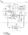
- a refrigeration system 1000A shown in FIG. 1 includes a heat source device 10A and a load device 20A that utilizes heat or cold heat generated by the heat source device 10A.
- the heat source device 10A includes a high temperature side circuit 101, a low temperature side circuit 102, and a control device 110.
- the high temperature side circuit 101 includes a compressor 1a, a heat exchanger 2, an expansion valve 3a, a heat exchanger 7, which is a cascade heat exchanger, and piping connecting them.
- the high temperature side circuit 101 constitutes a second refrigeration cycle device RC2 in which a second refrigerant circulates.
- the expansion valve 3a is connected to the evaporation side inlet of the heat exchanger 7.
- An evaporation-side outlet of the heat exchanger 7 is connected to the suction port of the compressor 1a.
- the low-temperature side circuit 102 includes a compressor 1b, a four-way valve 4, a heat exchanger 5 acting as an intercooler, a flow path switching device 6 in which four check valves are bridge-connected, a heat exchanger 7, It includes a liquid receiver 8 , an expansion valve 9 , a gas-liquid separator 10 , piping connecting these, a pressure sensor 51 , and a temperature sensor 52 .
- the low temperature side circuit 102 is connected to the load device 20A and constitutes a first refrigeration cycle device RC1 in which the first refrigerant circulates.
- the second refrigerant used in the second refrigeration cycle device RC2 is HFC refrigerant, HFO refrigerant, natural refrigerant (CO 2 , propane), etc.
- the first refrigerant used in the first refrigeration cycle device RC1 is CO 2 ( R744 refrigerant).
- the flow path switching device 6 includes check valves 61-64.
- the check valves 61-64 are arranged in a bridge shape as shown in FIG.
- the cooling operation outlet of the heat exchanger 5, the condensation side inlet of the heat exchanger 7, the liquid receiver 8 outlet, and the expansion valve 9 outlet are connected as shown in FIG.
- the load device 20A includes an expansion valve 3b, a load-side heat exchanger 11, and a fan 11F that are connected in series by piping. Note that the fan 11F is not essential.
- the heat source device 10A and the load device 20A are connected by piping.
- the control device 110 is a controller that appropriately operates each component of the heat source device 10A and the load device 20A.
- the control device 110 includes a CPU (Central Processing Unit) 111, a memory 112, and a communication interface (not shown).
- the CPU 111 controls each component of the heat source device 10A and the load device 20A according to the data stored in the memory 112 and the information obtained via the communication interface.
- the memory 112 includes, for example, ROM (Read Only Memory), RAM (Random Access Memory), and flash memory.
- the flash memory stores an operating system, application programs, and various data.
- Control device 110 shown in FIG. 1 is implemented by CPU 111 executing an operating system and application programs stored in memory 112 .
- Various data stored in the memory 112 are referenced when the application program is executed.
- the second refrigerant is discharged as a compressed refrigerant gas from the compressor 1a, condensed in the heat exchanger 2 on the heat source side, expanded to a low temperature and low pressure state in the expansion valve 3a, and evaporated in the heat exchanger 7. and is sucked into the compressor 1a.
- the refrigeration system 1000A has a cooling mode and a defrosting mode as operation modes.
- the cooling mode the first refrigerant flows in the direction indicated by the solid line arrow in FIG. 1, and in the defrosting mode, the first refrigerant flows in the direction indicated by the broken line arrow.
- the high-temperature, high-pressure gas (hot gas) of the first refrigerant discharged from the compressor 1b is introduced into the load-side heat exchanger 11 by the four-way valve 4 in the defrosting mode.
- the first refrigerant discharged from the compressor 1b of the low temperature side circuit 102 passes through the four-way valve 4 in the cooling operation direction, is primarily cooled by the heat exchanger 5, passes through the flow path switching device 6, and heat exchanges. It is condensed in the vessel 7, passes through the liquid receiver 8, the expansion valve 9, the flow path switching device 6 again, and flows into the load device 20A from the outlet of the heat source device 10A.
- the first refrigerant in a high-pressure liquid state that has flowed into the load device 20A from the heat source device 10A is expanded to a low-temperature, low-pressure state by the expansion valve 3b, evaporated in the load-side heat exchanger 11, and returned to the heat source device 10A in a low-pressure gas state. . Then, the first refrigerant returned from the load device 20A passes through the four-way valve 4 in the cooling operation direction and is sucked into the compressor 1b via the gas-liquid separator 10. As shown in FIG.
- the first refrigerant in a high-pressure gas state discharged from the compressor 1b of the low-temperature side circuit 102 passes through the four-way valve 4 in the defrosting operation direction, flows out from the heat source device 10A, and flows through the pipe connected to the load device 20A. flow into
- the first refrigerant in the high-pressure gas state that has entered the load device 20A is condensed while exchanging heat with frost in the load-side heat exchanger 11, passes through the expansion valve 3b, and returns to the heat source device 10A.
- the high-pressure first refrigerant returned from the load device 20A to the heat source device 10A passes through the flow path switching device 6, is further condensed in the heat exchanger 7, passes through the liquid receiver 8, and reaches the expansion valve 9.
- the first refrigerant is expanded to a low temperature and low pressure state by the expansion valve 9, passes through the flow switching device 6, evaporates in the heat exchanger 5, passes through the four-way valve 4 in the defrosting operation direction, and passes through the gas-liquid separator 10. and is sucked into the compressor 1b.
- the operation method of the high temperature side circuit 101 of the heat source device 10A does not change whether the low temperature side circuit 102 is in cooling operation or defrosting operation. However, for example, when the low-temperature side circuit 102 is in low-capacity operation during cooling operation and the refrigerant can be condensed only in the heat exchanger 5, the high-temperature side circuit 101 can be stopped. Further, when the refrigerant can be condensed only by the load device 20A during the defrosting operation, the high temperature side circuit 101 can be stopped.
- the heat exchanger 2 on the heat source side of the high temperature side circuit 101 includes types such as an air-cooled fin-coil heat exchanger and a water-cooled shell-and-tube heat exchanger, but is not particularly limited in this embodiment.
- a plate heat exchanger is mainly used as the heat exchanger 7 .
- As the heat exchanger 5 of the low temperature side circuit 102 an air-cooled fin coil type heat exchanger is mainly used. In this case, heat is exchanged between the refrigerant and the air by the fan motor and fan 5F, and control device 110 controls the rotational speed of the fan motor.
- the expansion valve 9 of the low-temperature side circuit 102 is controlled so that the degree of opening is fully open so as not to expand the liquid refrigerant flowing out of the liquid receiver 8 as much as possible.
- the expansion valve 9 is an electronic expansion valve
- the values detected by a pressure sensor and a temperature sensor are input to the control device 110, and the control device 110 performs pulse control of the electronic expansion valve.
- a circuit bypassing the expansion valve 9 may be provided to prevent flash gas from being generated in the liquid pipe.
- a solenoid valve or the like is installed in the bypass circuit so that the refrigerant does not pass through the bypass circuit during the defrosting operation.
- the expansion valve 9 of the low-temperature side circuit 102 keeps the degree of superheat of the refrigerant at the outlet of the heat exchanger 5 constant or the compressor suction pressure constant so that the refrigerant can evaporate in the heat exchanger 5.
- the expansion valve 9 is an electronic expansion valve
- the detected values of a pressure sensor and a temperature sensor are input to the control device 110, and the control device 110 performs pulse control of the electronic expansion valve.
- the control target value of the expansion valve 9 is not limited to the value described above, and can be changed as appropriate in order to stabilize the refrigeration cycle.
- the expansion valve 3b of the load device 20A expands the first refrigerant in the liquid state during the cooling operation, and is controlled to keep the degree of superheat of the refrigerant at the refrigerant outlet of the load-side heat exchanger 11 constant.
- the expansion valve 3b is an electronic expansion valve
- the detected values of a pressure sensor and a temperature sensor are input to the control device 110, and the control device 110 performs pulse control of the electronic expansion valve.
- the expansion valve 3b of the load device 20A is controlled to be fully open during the defrosting operation so that the liquid refrigerant condensed in the load side heat exchanger 11 is not expanded as much as possible.
- the expansion valve 3b is an electronic expansion valve
- the detected values of a pressure sensor and a temperature sensor (not shown) are input to the control device 110, and the control device 110 performs pulse control of the electronic expansion valve. If pressure loss occurs even when the expansion valve is fully opened, a flow path bypassing the expansion valve 3b may be provided to prevent an increase in the discharge pressure of the compressor 1b.
- an electromagnetic valve or the like is installed in the bypass channel so that the first refrigerant does not pass through the bypass channel during the cooling operation.
- the load-side heat exchanger 11 of the load device 20A includes types such as an air-cooled fin-coil heat exchanger and a plate-type heat exchanger, but the type is not particularly limited in this embodiment.
- An oil separator, a gas-liquid separator, a pressure sensor, a temperature sensor, a shutoff valve, etc. are not shown in the high temperature side circuit 101, but these may be installed as necessary.
- an oil separator, pressure sensor, temperature sensor, shutoff valve, etc. are not shown, but these may be installed as necessary.
- the gas-liquid separator 10 is shown in the drawing, the gas-liquid separator 10 may not be provided if it is judged unnecessary by appropriate control of the on-board equipment.
- control device 110 is provided in the heat source device 10A, but only the equipment control portion of the load device 20A may be separated from the control device 110 and installed near the load device 20A.
- the pressure sensor 51 of the low temperature side circuit 102 detects a pressure rise near the liquid receiver 8 .
- the control device 110 operates the high temperature side circuit 101 when the detected value of the pressure sensor 51 exceeds a certain threshold, and condenses the R744 refrigerant in the heat exchanger 7 to suppress the pressure increase.
- This threshold is set to a value with a margin for the design pressure.
- FIG. 2 is a flow chart for explaining the control of the compressor of the high temperature side circuit.
- control device 110 determines whether or not any one of the following three conditions (1) to (3) is satisfied.
- thermo-ON is established when the temperature of the cooling target space of the refrigerator rises above a thermo-ON threshold determined based on the target temperature.
- the value obtained by the pressure sensor 51 of the low temperature side circuit 102 is equal to or greater than the thermo ON threshold value (2) Satisfying the thermo ON determination (3)
- the determination in step S1 is repeatedly executed.
- control device 110 starts high temperature side circuit 101 in step S2. Specifically, the control device 110 starts the operation of the compressor 1a.
- control device 110 determines whether or not one of the following two conditions (1) to (2) is satisfied.
- thermo-OFF is established when the temperature of the cooling target space of the refrigerator falls below a thermo-OFF threshold that is determined based on the target temperature.
- (1) Thermo OFF determination is satisfied
- (2) There is a stop signal from the low temperature side circuit 102 If neither of the above two conditions is satisfied (NO in S3), the determination in step S3 is repeatedly executed.
- control device 110 stops high temperature side circuit 101 in step S4. Specifically, the control device 110 stops the operation of the compressor 1a.
- FIG. 3 is a flowchart for explaining fan control when the intercooler is air-cooled.
- the control device 110 determines whether or not the operation mode is the cooling mode.
- step S12 it is determined whether or not the outlet temperature of the heat exchanger 5 is higher than the determination value of "outside air temperature + ⁇ ". If the outlet temperature is high (YES in S12), the control device 110 rotates the fan 5F in step S13 so as to reduce heat radiation from the first refrigerant in order to prevent the evaporation load of the high-temperature side cycle from becoming too low. Decrease speed. On the other hand, if the outlet temperature is not higher than the determination value (NO in S12), control device 110 increases the rotational speed of fan 5F in step S14.
- ⁇ can be determined by desk design or experimentally so as to reflect the characteristics of the refrigeration system.
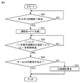
- FIG. 4 is a flowchart for explaining the control when the defrosting mode ends.
- the control device 110 In order to remove the frost generated in the heat exchanger 5 during the hot gas defrosting operation, the control device 110 forcibly operates the refrigerating device at the end of the defrosting mode regardless of whether the thermostat is ON or OFF.
- step S21 the control device 110 determines whether or not the conditions for ending the defrost mode are satisfied.
- Conditions for terminating the defrost mode are, for example, when a certain period of time has elapsed after shifting to the defrost mode, when the load side heat exchanger 11 is monitored to detect that defrosting has ended, and when the load side This is established when an increase in the temperature of the refrigerant passing through the heat exchanger 11 is detected.
- step S21 if the conditions for ending the defrosting mode are not met (NO in S21), the control device 110 continues the determination in step S21. On the other hand, in step S21, if the condition for ending the defrosting mode is satisfied (YES in S21), control device 110 changes the operation mode to the cooling mode in step S22. In the cooling mode, switching of the four-way valve 4 changes the flow direction of the refrigerant as indicated by the broken line arrow in FIG. 1 and the solid line arrow.
- control device 110 determines whether or not the following condition (1) or (2) is satisfied.
- (1) The refrigerant temperature at the outlet of the heat exchanger 5 is higher than ⁇ °C.
- (2) A certain period of time has elapsed since the start of the cooling operation mode.
- the judgment value of the outlet refrigerant temperature of the heat exchanger 5 The value of ⁇ that can achieve frost removal can be determined by desk study or test. Also, the fixed time corresponding to the forced operation time can be similarly determined by desk study or test.
- step S23 if the conditions (1) and (2) are not satisfied (NO in S23), the control device 110 continues the determination in step S23. On the other hand, if one of the conditions (1) and (2) is satisfied in step S23 (YES in S23), control device 110 determines in step S24 whether the result of thermo ON determination is thermo ON. determine whether or not If the result of the thermo ON determination is that the thermo is ON (YES at S24), the processing of the flowchart of FIG. 4 is terminated as it is. Control the refrigerator to the OFF state.
- FIG. 4 shows an example of the forced operation method after the defrosting operation, and conditions not shown or cooperation with protective control can be implemented as appropriate.
- FIG. 5 is a diagram showing the configuration of a refrigeration system according to Embodiment 2.
- FIG. A refrigeration system 1000B shown in FIG. 5 includes a heat source device 10B and a load device 20A.
- the heat source device 10B includes a high temperature side circuit 101, a low temperature side circuit 102B, and a control device 110.
- Refrigeration system 1000B of the second embodiment shown in FIG. 5 differs from refrigeration system 1000A of the first embodiment shown in FIG. It is that the flow path 22 bypassing the expansion valve 9 and the flow path switching device 6 and the check valve 21 provided in the flow path 22 are added in the middle of the connected piping.
- the direction of the check valve 21 is the direction in which the refrigerant flows from the liquid receiver 8 toward the load device 20A.
- the configuration of other parts is the same as that of FIG. 1, so description thereof will not be repeated.
- the check valve 21 supplies liquid refrigerant from the heat source device 10B without going through the expansion valve 9 when a pressure drop occurs even if the opening of the expansion valve 9 is fully opened while the low temperature side circuit 102B is performing cooling operation. to prevent the generation of flash gas in the liquid piping.
- the flow path resistance of the expansion valve 9 becomes larger than the flow path resistance of the check valve 21, so the refrigerant flows to the check valve 21 side.
- shutoff valve such as an electromagnetic valve before and after the check valve 21.
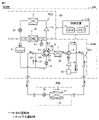
- FIG. 6 is a diagram showing the configuration of a refrigeration system according to Embodiment 3.
- FIG. A refrigerating device 1000C shown in FIG. 6 includes a heat source device 10C and a load device 20A.
- the heat source device 10C includes a high temperature side circuit 101C, a low temperature side circuit 102, and a control device 110.
- a refrigerating device 1000C according to the third embodiment shown in FIG. 6 differs from the refrigerating device 1000A according to the first embodiment shown in FIG.
- a bypass flow path 32 that branches from the middle of the pipe connecting the expansion valve 3 a and the heat exchanger 7 and flows the second refrigerant toward the middle of the pipe connecting the expansion valve 3 a and the heat exchanger 7 .
- the expansion valve 31 is added.
- the configuration of other parts is the same as that of FIG. 1, so description thereof will not be repeated.
- the detected values of the pressure sensor and temperature sensor are input to the control device 110, and the control device 110 performs pulse control of the electronic expansion valve.
- the evaporation load on the heat exchanger 7 can be reduced. Therefore, when the condensation load of the low-temperature side circuit 102 is small, the high-temperature side circuit 101C can be operated at an appropriate degree of superheat, and the return (liquid return) of the second refrigerant in the liquid state to the compressor 1a can be prevented. It is possible to prevent excessive starting and stopping repetitions.
- Embodiment 3 when a large amount of refrigerant is allowed to flow through the bypass passage 32, the condensation pressure in the heat exchanger 2 on the heat source side becomes low, so the refrigerant bypass amount to the bypass passage 32 becomes small.
- the expansion valve 31 installed in the bypass flow path 32 is fully opened, if the evaporation capacity increases with respect to the evaporation load, liquid returns to the compressor 1a.
- FIG. 7 is a flowchart for explaining control for liquid return prevention executed in the third embodiment. The processing of this flowchart is called and executed at regular time intervals from the main routine for controlling the second refrigeration cycle device RC2.
- step S31 the control device 110 determines whether or not the liquid return determination condition is satisfied. If the conditions for liquid return determination are not satisfied (NO in S31), that is, if liquid return to the compressor 1a does not occur, the process returns to the main routine. If the conditions for liquid return determination are satisfied (YES in S31), the control device 110 determines in step S32 whether or not the degree of opening of the expansion valve 3a is minimum.
- the controller 110 reduces the opening of the expansion valve 3a in step S33.
- a predetermined fixed value can be used as the width of decrease in this case.
- step S33 the controller 110 determines whether the opening degree of the expansion valve 31 provided in the bypass flow path 32 is maximum. to decide.
- the controller 110 increases the degree of opening of the expansion valve 31 in step S35.
- a predetermined fixed value can be used as the increase width in this case.
- controller 110 increases the high temperature side target condensing temperature or decreases the high temperature side target evaporating temperature in step S36, or Do them at the same time.
- the refrigerating capacity of the second refrigerating cycle device RC2 can be forcibly reduced, the amount of refrigerant passing through the bypass flow path 32 can be optimized, and liquid return to the compressor 1a can be prevented. be able to.
- check valve 21 in the second embodiment is not provided in the third embodiment, the second embodiment and the third embodiment can be combined as needed.
- Embodiment 4 When the heat source device 10A shown in FIG. 1 is an air-cooled type, it is common to select heat exchangers having the same structure for the high-temperature side cycle and the low-temperature side cycle.
- the condenser on the heat source machine side of the refrigeration system is an air heat exchanger
- the condenser described in International Publication No. 2020/161803 Patent Document 1 can be the same type of heat exchanger. It is common as However, when a defrosting operation is performed using hot gas, frosting occurs in the heat exchanger 5, and clogging or the like occurs when a high-efficiency PFC heat exchanger is used.
- a plate-fin tube air heat exchanger is adopted as the heat exchanger 5 of the low temperature side circuit 102 in the heat source equipment 10A.
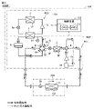
- FIG. 8 is a diagram showing the configuration of a refrigeration system according to Embodiment 5.
- a refrigerating device 1000D shown in FIG. 8 includes a heat source device 10D and a load device 20A.
- the heat source device 10D includes a high temperature side circuit 101, a low temperature side circuit 102D, and a control device 110.
- the low temperature side circuit 102D of the second embodiment shown in FIG. 8 differs from the low temperature side circuit 102 of the first embodiment shown in FIG. The only difference is that a vessel 12 and a decompression device 13 for injection are added.
- the injection flow path 14 branches from the flow path connecting the fourth heat exchanger 12 and the expansion valve 3b, and returns the first refrigerant to the compression intermediate portion of the compressor 1b.
- the decompression device 13 decompresses the first refrigerant flowing through the branched flow path.
- the fourth heat exchanger 12 cools the first refrigerant flowing from the flow path switching device 6 to the expansion valve 3b with the first refrigerant whose temperature has been lowered by the pressure reduction device 13 in the injection flow path 14. do.
- the rest of the configuration of the low temperature side circuit 102D is the same as the low temperature side circuit 102 described in FIG. 1, so the description will not be repeated here.
- the flow rate of the refrigerant flowing through the injection flow path 14 is designed based on control target values (degree of superheat, compressor discharge temperature, or liquid temperature) obtained theoretically or experimentally.
- control target values degree of superheat, compressor discharge temperature, or liquid temperature
- an electronic expansion valve, a thermal expansion valve, a capillary tube, or the like is selected.
- the fourth heat exchanger 12 is shown in FIG. 9, only the pressure reducing device 13 for injection may be arranged in the injection flow path 14 without providing the fourth heat exchanger 12 .
- FIG. 9 is a diagram showing the configuration of a refrigeration system according to Embodiment 6.
- FIG. A refrigeration system 1000E shown in FIG. 9 includes a heat source device 10E and a load device 20A.
- the heat source device 10E includes a high temperature side circuit 101, a low temperature side circuit 102E, and a control device 110.
- a low temperature side circuit 102E of Embodiment 2 shown in FIG. 8 differs from a low temperature side circuit 102D of Embodiment 5 shown in FIG. That is the point.
- the injection flow path 14E branches from the flow path connecting the fourth heat exchanger 12 and the expansion valve 3b, and returns the first refrigerant to the suction port of the compressor 1b.
- FIG. 9 Other parts of the configuration of the low temperature side circuit 102E are the same as those of the low temperature side circuit 102D described with reference to FIG. 8, so description thereof will not be repeated here.
- the fourth heat exchanger 12 is shown in FIG. 9, the pressure reducing device 13 for injection may be arranged in the injection flow path 14E without providing the fourth heat exchanger 12.
- Embodiment 7 shows an example in which the arrangement of the expansion valve 9 is changed.
- FIG. 10 is a diagram showing the configuration of a refrigeration system according to Embodiment 7.
- FIG. A refrigeration system 1000F shown in FIG. 10 includes a heat source device 10F and a load device 20A.
- the heat source equipment 10F includes a high temperature side circuit 101, a low temperature side circuit 102F, and a control device 110.
- a refrigeration system 1000F of Embodiment 7 shown in FIG. 10 differs from the refrigeration system 1000A of Embodiment 1 shown in FIG.
- the expansion valve 9 ⁇ /b>F is arranged between the heat exchanger 5 and the flow switching device 6 . 10 is the same as that of FIG. 1, the description of other parts will not be repeated.
- the expansion valve 9 may be anywhere in the flow path from the liquid receiver 8 to the heat exchanger 5 in the flow of refrigerant during defrosting operation. Therefore, the expansion valve 9 of FIG. 1 can be moved and arranged like the expansion valve 9F of FIG.
- FIG. 11 is a diagram showing another example of the arrangement of expansion valves.
- the expansion valve 9G is arranged in series with the check valve 62 in the flow path switching device 6.
- the modification shown in FIG. 11 is a diagram showing another example of the arrangement of expansion valves.
- the expansion valve 9G is arranged in series with the check valve 62 in the flow path switching device 6.
- the expansion valve 3b of the load device 20A may not be installed. 10 and 11, the expansion valve 3b must be installed to perform decompression expansion during the cooling operation.
- the present disclosure relates to a heat source device 10A that forms a refrigeration system 1000A together with a load device 20A.
- the refrigeration system 1000A has a cooling mode and a defrosting mode as operation modes.
- the heat source device 10A includes a first compressor (1b), a first heat exchanger (7), a second heat exchanger (5), and a liquid receiver 8.
- the heat source device 10A further includes a four-way valve 4 and a channel switching device 6 .
- the four-way valve 4 switches the connection destinations of the load device 20A and the second heat exchanger (5) between the cooling mode and the defrosting mode.
- the flow path switching device 6 includes an upstream portion of a flow path through which the first refrigerant flows to the liquid receiver 8 via the first heat exchanger (7), a downstream portion of the flow path, a load device 20A, and a second heat exchanger. It is connected to the exchanger (5) and switches the flow of the first refrigerant.
- the downstream part is located downstream of the flow path through which the first refrigerant flows to the liquid receiver 8 via the first heat exchanger (7).
- the first refrigerant circulates through the load device 20A and the four-way valve 4 in order and returns to the first compressor (1b).
- the first refrigerant circulates through the heat exchanger (5) and the four-way valve 4 in order and returns to the first compressor (1b).
- the channel switching device 6 includes first to fourth check valves 61-64.
- the first check valve 61 is arranged between the load device 20A and the first heat exchanger (7) in a direction in which the first refrigerant flows from the load device 20A to the first heat exchanger (7).
- the second check valve 62 is positioned between the outlet of the liquid receiver 8 and the second heat exchanger (5) in the direction in which the first refrigerant flows from the outlet of the liquid receiver 8 to the second heat exchanger (5). placed in A third check valve 63 provides a first flow from the second heat exchanger (5) to the first heat exchanger (7) between the second heat exchanger (5) and the first heat exchanger (7). It is arranged in the direction in which the coolant flows.
- the fourth check valve 64 is arranged between the outlet of the liquid receiver 8 and the load device 20A in the direction in which the first refrigerant flows from the outlet of the liquid receiver 8 to the load device 20A.
- the heat source device 10A further includes an expansion valve 9 that adjusts the flow rate of the first refrigerant.
- the expansion valve 9 is provided on a path through which the first refrigerant flows from the outlet of the liquid receiver 8 to the second heat exchanger (5) in the defrosting mode.
- the heat source device 10B is branched from the pipe connecting the liquid receiver 8 and the expansion valve 9, bypasses the expansion valve 9 and the flow path switching device 6, and connects to the load device 20A. Further provided are a bypass flow path 22 through which the first refrigerant flows, and a fifth check valve 21 provided in the bypass flow path 22 and configured to flow the refrigerant from the liquid receiver 8 toward the load device 20A.
- the heat source device 10A further includes a second compressor (1a), a third heat exchanger (2), and an expansion valve 3a.
- the second compressor (1a), the third heat exchanger (2), and the expansion valve 3a together with the first heat exchanger (7) constitute a second refrigeration cycle device RC2 in which the second refrigerant sequentially circulates.
- a first heat exchanger (7) is configured to exchange heat between a first refrigerant and a second refrigerant.
- the second refrigeration cycle device RC2 may not necessarily be provided.
- the first heat exchanger (7) may exchange heat between water or brine and the first refrigerant.
- the heat source device 10C is branched from the middle of the pipe connecting the second compressor (1a) and the third heat exchanger (2).
- a bypass passage 32 for flowing the second refrigerant through a pipe connecting the expansion valve 3a and the first heat exchanger (7), and an expansion valve 31 provided in the bypass passage 32 for adjusting the flow rate of the second refrigerant. further provide.
- the third heat exchanger (2) is a parallel flow condenser heat exchanger
- the second heat exchanger (5) is a plate fin tube air heat exchanger
- the heat source device 10C further includes a control device 110 that controls the expansion valve 31.
- the control device 110 is configured to increase the degree of opening of the expansion valve 31 when it is determined that liquid return occurs in which the first refrigerant in the liquid state is sucked into the second compressor (1a).
- the controller 110 sets the target condensation temperature and the target evaporation temperature of the second refrigeration cycle device RC2. Configured to change temperature.
- the heat source devices 10A to 10F are provided in one of the paths from the flow path switching device 6 to the liquid receiver 8 via the first heat exchanger (7) and detect the pressure of the first refrigerant.
- a sensor 51 is further provided.
- the second refrigeration cycle device RC2 is configured to start operation when the pressure sensor 51 detection value exceeds the judgment value.
- the second heat exchanger (5) is a plate-fin tube heat exchanger that exchanges heat between air and the first refrigerant.
- the heat source device 10A further includes a control device 110 that controls the first compressor (1b), the four-way valve 4, and the flow path switching device 6 to switch the operation mode.
- the control device 110 forces the first compressor (1b) to operate continuously for a certain period of time.
- the heat source device 10A further includes a control device 110 that controls the first compressor (1b), the four-way valve 4, and the flow path switching device 6 to switch the operation mode.
- the control device 110 determines whether a certain period of time has elapsed or the refrigerant temperature at the refrigerant outlet of the second heat exchanger (5) has reached the judgment value.
- the first compressor (1b) is forcibly operated continuously until it reaches.
- the heat source device 10D includes an injection passage 14 for returning part of the second refrigerant discharged from the liquid receiver 8 to the first compressor (1b), and and a decompression device 13 arranged therein.
- the heat source device 10D performs heat exchange between the first refrigerant discharged from the liquid receiver 8 and the first refrigerant that has passed through the pressure reducing device 13 in the defrosting mode.
- a fourth heat exchanger 12 is further provided.
- the present disclosure relates to a refrigeration system 1000A including any one of the heat source devices 10A to 10E described above and a load device 20A.
- the return refrigerant from the load-side heat exchanger 11 is switched to the heat exchanger 7 and the A refrigerant circuit passing through the liquid receiver 8 is constructed.
Landscapes
- Engineering & Computer Science (AREA)
- Physics & Mathematics (AREA)
- Mechanical Engineering (AREA)
- Thermal Sciences (AREA)
- General Engineering & Computer Science (AREA)
- Chemical & Material Sciences (AREA)
- Chemical Kinetics & Catalysis (AREA)
- Devices That Are Associated With Refrigeration Equipment (AREA)
- Air Conditioning Control Device (AREA)
Priority Applications (3)
| Application Number | Priority Date | Filing Date | Title |
|---|---|---|---|
| PCT/JP2021/010638 WO2022195727A1 (ja) | 2021-03-16 | 2021-03-16 | 冷凍装置の熱源機およびそれを備える冷凍装置 |
| DE112021007291.9T DE112021007291T5 (de) | 2021-03-16 | 2021-03-16 | Wärmequellenmaschine einer Kühlvorrichtung und Kühlvorrichtung einschließlich derselben |
| JP2023506449A JP7523667B2 (ja) | 2021-03-16 | 2021-03-16 | 冷凍装置の熱源機およびそれを備える冷凍装置 |
Applications Claiming Priority (1)
| Application Number | Priority Date | Filing Date | Title |
|---|---|---|---|
| PCT/JP2021/010638 WO2022195727A1 (ja) | 2021-03-16 | 2021-03-16 | 冷凍装置の熱源機およびそれを備える冷凍装置 |
Publications (1)
| Publication Number | Publication Date |
|---|---|
| WO2022195727A1 true WO2022195727A1 (ja) | 2022-09-22 |
Family
ID=83320156
Family Applications (1)
| Application Number | Title | Priority Date | Filing Date |
|---|---|---|---|
| PCT/JP2021/010638 Ceased WO2022195727A1 (ja) | 2021-03-16 | 2021-03-16 | 冷凍装置の熱源機およびそれを備える冷凍装置 |
Country Status (3)
| Country | Link |
|---|---|
| JP (1) | JP7523667B2 (https=) |
| DE (1) | DE112021007291T5 (https=) |
| WO (1) | WO2022195727A1 (https=) |
Cited By (1)
| Publication number | Priority date | Publication date | Assignee | Title |
|---|---|---|---|---|
| WO2024154207A1 (ja) * | 2023-01-16 | 2024-07-25 | 三菱電機株式会社 | 二元冷凍装置 |
Citations (7)
| Publication number | Priority date | Publication date | Assignee | Title |
|---|---|---|---|---|
| JPH01277173A (ja) * | 1988-04-21 | 1989-11-07 | American Standard Inc | 冷却システム |
| JP2007178106A (ja) * | 2005-12-28 | 2007-07-12 | Hitachi Ltd | 冷却装置 |
| WO2014038028A1 (ja) * | 2012-09-06 | 2014-03-13 | 三菱電機株式会社 | 冷凍装置 |
| JP2017040464A (ja) * | 2014-09-03 | 2017-02-23 | 三星電子株式会社Samsung Electronics Co.,Ltd. | 冷媒量検知装置 |
| WO2017199382A1 (ja) * | 2016-05-18 | 2017-11-23 | 三菱電機株式会社 | 冷凍装置 |
| WO2018142583A1 (ja) * | 2017-02-03 | 2018-08-09 | 三菱電機株式会社 | 冷凍システム |
| WO2020161803A1 (ja) * | 2019-02-05 | 2020-08-13 | 三菱電機株式会社 | 冷凍装置の室外機およびそれを備える冷凍装置 |
Family Cites Families (3)
| Publication number | Priority date | Publication date | Assignee | Title |
|---|---|---|---|---|
| JP4966742B2 (ja) | 2007-05-25 | 2012-07-04 | 日立アプライアンス株式会社 | 空気調和機 |
| JP2012198020A (ja) | 2012-06-21 | 2012-10-18 | Mitsubishi Heavy Ind Ltd | 空調システム及び空調システムの油戻し制御方法 |
| JP2015224846A (ja) | 2014-05-29 | 2015-12-14 | パナソニックIpマネジメント株式会社 | 冷凍サイクル装置 |
-
2021
- 2021-03-16 WO PCT/JP2021/010638 patent/WO2022195727A1/ja not_active Ceased
- 2021-03-16 JP JP2023506449A patent/JP7523667B2/ja active Active
- 2021-03-16 DE DE112021007291.9T patent/DE112021007291T5/de active Pending
Patent Citations (7)
| Publication number | Priority date | Publication date | Assignee | Title |
|---|---|---|---|---|
| JPH01277173A (ja) * | 1988-04-21 | 1989-11-07 | American Standard Inc | 冷却システム |
| JP2007178106A (ja) * | 2005-12-28 | 2007-07-12 | Hitachi Ltd | 冷却装置 |
| WO2014038028A1 (ja) * | 2012-09-06 | 2014-03-13 | 三菱電機株式会社 | 冷凍装置 |
| JP2017040464A (ja) * | 2014-09-03 | 2017-02-23 | 三星電子株式会社Samsung Electronics Co.,Ltd. | 冷媒量検知装置 |
| WO2017199382A1 (ja) * | 2016-05-18 | 2017-11-23 | 三菱電機株式会社 | 冷凍装置 |
| WO2018142583A1 (ja) * | 2017-02-03 | 2018-08-09 | 三菱電機株式会社 | 冷凍システム |
| WO2020161803A1 (ja) * | 2019-02-05 | 2020-08-13 | 三菱電機株式会社 | 冷凍装置の室外機およびそれを備える冷凍装置 |
Cited By (1)
| Publication number | Priority date | Publication date | Assignee | Title |
|---|---|---|---|---|
| WO2024154207A1 (ja) * | 2023-01-16 | 2024-07-25 | 三菱電機株式会社 | 二元冷凍装置 |
Also Published As
| Publication number | Publication date |
|---|---|
| JP7523667B2 (ja) | 2024-07-26 |
| JPWO2022195727A1 (https=) | 2022-09-22 |
| DE112021007291T5 (de) | 2024-01-18 |
Similar Documents
| Publication | Publication Date | Title |
|---|---|---|
| JP5452138B2 (ja) | 冷凍空調装置 | |
| JP5595245B2 (ja) | 冷凍装置 | |
| US11268743B2 (en) | Air-conditioning apparatus having heating-defrosting operation mode | |
| US10415861B2 (en) | Refrigeration cycle apparatus | |
| EP3062031B1 (en) | Air conditioner | |
| JP7112057B1 (ja) | 空気調和装置 | |
| US11796212B2 (en) | Air-conditioning apparatus | |
| CN204301351U (zh) | 热泵式热水供给器 | |
| JPWO2020194435A1 (ja) | 空気調和装置 | |
| JP2011179697A (ja) | 冷凍サイクル装置および冷温水装置 | |
| JP5404761B2 (ja) | 冷凍装置 | |
| JP2023503192A (ja) | 空気調和装置 | |
| KR101692243B1 (ko) | 캐스캐이드 사이클을 이용한 히트 펌프 | |
| JP2008134031A (ja) | 非共沸混合冷媒を用いた冷凍装置 | |
| JP7523667B2 (ja) | 冷凍装置の熱源機およびそれを備える冷凍装置 | |
| JP6206787B2 (ja) | 冷凍装置 | |
| JP7489932B2 (ja) | ハイブリッド温水暖房システム | |
| JP5496161B2 (ja) | 冷凍サイクルシステム | |
| JP2020003156A (ja) | 冷凍サイクル装置およびそれを備えた液体加熱装置 | |
| JP4096984B2 (ja) | 冷凍装置 | |
| JP2013124843A (ja) | 冷凍サイクルシステム | |
| JP2009293887A (ja) | 冷凍装置 | |
| JP2002228284A (ja) | 冷凍装置 | |
| JP4906885B2 (ja) | 冷凍サイクル装置 | |
| CN114402171A (zh) | 热泵 |
Legal Events
| Date | Code | Title | Description |
|---|---|---|---|
| 121 | Ep: the epo has been informed by wipo that ep was designated in this application |
Ref document number: 21931479 Country of ref document: EP Kind code of ref document: A1 |
|
| ENP | Entry into the national phase |
Ref document number: 2023506449 Country of ref document: JP Kind code of ref document: A |
|
| WWE | Wipo information: entry into national phase |
Ref document number: 112021007291 Country of ref document: DE |
|
| 122 | Ep: pct application non-entry in european phase |
Ref document number: 21931479 Country of ref document: EP Kind code of ref document: A1 |