WO2022191282A1 - 車載伝送システム - Google Patents
車載伝送システム Download PDFInfo
- Publication number
- WO2022191282A1 WO2022191282A1 PCT/JP2022/010569 JP2022010569W WO2022191282A1 WO 2022191282 A1 WO2022191282 A1 WO 2022191282A1 JP 2022010569 W JP2022010569 W JP 2022010569W WO 2022191282 A1 WO2022191282 A1 WO 2022191282A1
- Authority
- WO
- WIPO (PCT)
- Prior art keywords
- digital signal
- side communication
- vehicle
- communication unit
- roof
- Prior art date
- Legal status (The legal status is an assumption and is not a legal conclusion. Google has not performed a legal analysis and makes no representation as to the accuracy of the status listed.)
- Ceased
Links
Images


Classifications
-
- H—ELECTRICITY
- H04—ELECTRIC COMMUNICATION TECHNIQUE
- H04B—TRANSMISSION
- H04B1/00—Details of transmission systems, not covered by a single one of groups H04B3/00 - H04B13/00; Details of transmission systems not characterised by the medium used for transmission
- H04B1/38—Transceivers, i.e. devices in which transmitter and receiver form a structural unit and in which at least one part is used for functions of transmitting and receiving
- H04B1/3822—Transceivers, i.e. devices in which transmitter and receiver form a structural unit and in which at least one part is used for functions of transmitting and receiving specially adapted for use in vehicles
-
- H—ELECTRICITY
- H01—ELECTRIC ELEMENTS
- H01Q—ANTENNAS, i.e. RADIO AERIALS
- H01Q1/00—Details of, or arrangements associated with, antennas
- H01Q1/27—Adaptation for use in or on movable bodies
- H01Q1/32—Adaptation for use in or on road or rail vehicles
-
- H—ELECTRICITY
- H01—ELECTRIC ELEMENTS
- H01Q—ANTENNAS, i.e. RADIO AERIALS
- H01Q1/00—Details of, or arrangements associated with, antennas
- H01Q1/50—Structural association of antennas with earthing switches, lead-in devices or lightning protectors
-
- H—ELECTRICITY
- H04—ELECTRIC COMMUNICATION TECHNIQUE
- H04B—TRANSMISSION
- H04B1/00—Details of transmission systems, not covered by a single one of groups H04B3/00 - H04B13/00; Details of transmission systems not characterised by the medium used for transmission
-
- H—ELECTRICITY
- H04—ELECTRIC COMMUNICATION TECHNIQUE
- H04B—TRANSMISSION
- H04B1/00—Details of transmission systems, not covered by a single one of groups H04B3/00 - H04B13/00; Details of transmission systems not characterised by the medium used for transmission
- H04B1/06—Receivers
- H04B1/16—Circuits
- H04B1/18—Input circuits, e.g. for coupling to an antenna or a transmission line
-
- H—ELECTRICITY
- H04—ELECTRIC COMMUNICATION TECHNIQUE
- H04B—TRANSMISSION
- H04B1/00—Details of transmission systems, not covered by a single one of groups H04B3/00 - H04B13/00; Details of transmission systems not characterised by the medium used for transmission
- H04B1/38—Transceivers, i.e. devices in which transmitter and receiver form a structural unit and in which at least one part is used for functions of transmitting and receiving
- H04B1/40—Circuits
- H04B1/403—Circuits using the same oscillator for generating both the transmitter frequency and the receiver local oscillator frequency
- H04B1/405—Circuits using the same oscillator for generating both the transmitter frequency and the receiver local oscillator frequency with multiple discrete channels
Definitions
- the present disclosure relates to in-vehicle transmission systems.
- This application claims priority based on Japanese Patent Application No. 2021-39803 filed on March 12, 2021, and incorporates all of its disclosure herein.
- Patent Document 1 Japanese Patent Application Laid-Open No. 2009-177785 discloses the following technique. That is, an in-vehicle radio communication device includes a plurality of antennas with different frequencies, a multiplexing circuit, a demultiplexer circuit, and a plurality of radio units corresponding to the plurality of antennas with different frequencies, circuit or the branching circuit, and further installed on the roof of the vehicle, above the windshield, or above the rear glass together with the connected combining circuit or the branching circuit, and the plurality of wireless devices is connected to either the diplexer circuit or the multiplexer circuit opposite to the antenna by a wireless device side antenna cable, and the multiplexer circuit and the multiplexer circuit are routed through the pillar on the antenna device side It is connected by an antenna cable.
- An in-vehicle transmission system includes a vehicle interior communication unit that generates a digital signal including a plurality of data corresponding to a plurality of frequency bands that are different from each other, and transmits the generated digital signal to one transmission line; a roof-side communication unit that distributes the digital signal received from the transmission line or a signal based on the digital signal received from the transmission line to a plurality of wireless devices respectively corresponding to the plurality of frequency bands.
- One aspect of the present disclosure can be realized not only as an in-vehicle transmission system including such a characteristic processing unit, but also as a program for causing a computer to execute steps of such characteristic processing, or as an in-vehicle transmission system. It can be implemented as a semiconductor integrated circuit that implements part or all of the transmission system.
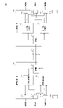
- FIG. 1 is a diagram showing the configuration of an in-vehicle transmission system according to the first embodiment of the present disclosure.
- FIG. 2 is a diagram showing the configuration of an in-vehicle transmission system according to the first embodiment of the present disclosure.
- FIG. 3 is a diagram showing the configuration of an in-vehicle transmission system according to the first embodiment of the present disclosure.
- FIG. 4 is a diagram illustrating an example of a transmission processing sequence in the vehicle-mounted transmission system according to the first embodiment of the present disclosure.
- FIG. 5 is a diagram showing the configuration of an in-vehicle transmission system according to a modification of the first embodiment of the present disclosure.
- FIG. 6 is a diagram showing the configuration of an in-vehicle transmission system according to a modification of the first embodiment of the present disclosure.
- FIG. 7 is a diagram showing the configuration of an in-vehicle transmission system according to the second embodiment of the present disclosure.
- FIG. 8 is a diagram showing the configuration of an in-vehicle transmission system according to the second embodiment of the present disclosure.
- FIG. 9 is a diagram illustrating an example of a sequence of transmission processing in the vehicle-mounted transmission system according to the second embodiment of the present disclosure.
- FIG. 10 is a diagram showing the configuration of an in-vehicle transmission system according to a modification of the second embodiment of the present disclosure.
- FIG. 11 is a diagram showing the configuration of an in-vehicle transmission system according to a modification of the second embodiment of the present disclosure.
- FIG. 12 is a diagram showing the configuration of an in-vehicle transmission system according to the third embodiment of the present disclosure.
- a technology capable of realizing excellent functions related to signal transmission between the roof-side communication unit and the vehicle-interior communication unit In an in-vehicle environment where the number of communication services to be provided tends to increase, there is a demand for a technology capable of realizing excellent functions related to signal transmission between the roof-side communication unit and the vehicle-interior communication unit.
- the present disclosure has been made to solve the above-described problems, and its object is to realize excellent functions related to signal transmission between the roof-side communication unit and the passenger compartment-side communication unit. It is to provide an in-vehicle transmission system that is
- An in-vehicle transmission system generates a digital signal including a plurality of data corresponding to a plurality of frequency bands different from each other, and transmits the generated digital signal to one transmission line.
- a vehicle interior side communication unit and roof side communication for distributing the digital signal received from the transmission line or a signal based on the digital signal received from the transmission line to a plurality of radios corresponding to the plurality of frequency bands. and a part.
- the passenger compartment side communication section generates a digital signal including a plurality of data corresponding to a plurality of mutually different frequency bands and transmits the digital signal to one transmission line
- the roof side communication section receives the digital signal from the transmission line.
- the roof-side communication unit may include a distribution unit provided between the transmission line and the plurality of radios, and a plurality of ports to which the plurality of radios can be connected, respectively.
- the distribution unit may distribute the digital signal from the transmission line to the plurality of ports.
- the radio when the radio is connected to the port, the digital signal transmitted from the vehicle interior side communication unit or a signal based on the digital signal can be transmitted to the radio. Radios can be easily added to vehicles.
- the vehicle interior side communication unit transmits, as the digital signal, a 1-bit width RF (Radio Frequency) signal in which amplitude and phase information appear as sparse and dense bit strings on the time axis to the transmission path.
- RF Radio Frequency
- the vehicle interior side communication section may transmit the digital signal subjected to error correction coding processing to the transmission line, and the roof side communication section may transmit the digital signal received from the transmission line. Error correction processing may be performed.
- the transmission line Since the influence of noise in the vehicle can be mitigated, the communication quality in the vehicle-mounted transmission system can be improved.
- FIG. 1 is a diagram showing the configuration of an in-vehicle transmission system according to the first embodiment of the present disclosure.
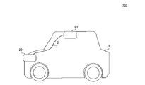
- in-vehicle transmission system 301 includes roof-side communication section 101 , cabin-side communication section 201 , and path section 2 .
- the in-vehicle transmission system 301 is mounted on the vehicle 1 .
- a first end and a second end of the path portion 2 are connected to the roof side communication portion 101 and the passenger compartment side communication portion 201, respectively.
- Path portion 2 is installed, for example, through the right front pillar of vehicle 1 .
- the path section 2 includes one or more transmission lines.
- the roof-side communication unit 101 is installed on the roof of the vehicle 1. Specifically, roof-side communication unit 101 is installed, for example, in a space between the sheet metal and the inner lining on the roof of vehicle 1 . As will be described later, the roof-side communication unit 101 is connected to a plurality of wireless devices. Roof-side communication section 101 receives RF signals from a plurality of wireless devices corresponding to a plurality of frequency bands different from each other, and transmits digital signals based on the received RF signals to one transmission line in path section 2 .
- the cabin-side communication unit 201 is installed in the cabin of the vehicle 1. Specifically, vehicle interior side communication unit 201 is installed, for example, in a space within the dashboard of vehicle 1 . In addition, the vehicle interior side communication unit 201 may be arranged on the floor of the vehicle 1, may be arranged on the instrument panel, or may be arranged on the trunk, for example.
- the vehicle interior side communication section 201 processes the digital signal received from the transmission line in the path section 2 for each frequency band.
- FIG. 2 is a diagram showing the configuration of an in-vehicle transmission system according to the first embodiment of the present disclosure.
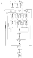
- FIG. 2 shows a detailed configuration of the roof-side communication section 101.
- roof-side communication unit 101 includes ports 111A, 111B, 111C, and 111D, a roof-side receiving unit 121, and a communication unit 141.
- Roof-side receiver 121 includes AD (Analog to Digital) converters 131A, 131B, 131C, and 131D, demodulators 132A, 132B, 132C, and 132D, a combiner 133, and an encoder .
- AD Analog to Digital
- each of ports 111A, 111B, 111C, and 111D will also be referred to as port 111
- each of AD converters 131A, 131B, 131C, and 131D will also be referred to as AD converter 131
- each of demodulators 132A, 132B, 132C, and 132D will be referred to as Also referred to as a demodulator 132
- AD converter 131 is realized by an IC (Integrated Circuit), for example.
- the demodulator 132, the synthesizer 133 and the encoder 134 are implemented by processors such as a CPU (Central Processing Unit) and a DSP (Digital Signal Processor).
- Communication unit 141 is realized by, for example, a communication IC.
- the roof-side communication unit 101 may include two, three, or five or more ports 111, or may include two, three, or five or more AD conversion units 131. Alternatively, the configuration may include two, three, or five or more demodulators 132 .
- the communication section 141 in the roof side communication section 101 is connected to the path section 2 . More specifically, the path section 2 includes a transmission line 3 .
- the communication unit 141 is connected to the transmission line 3 .
- the transmission line 3 is a cable conforming to Ethernet (registered trademark), USB (Universal Serial Bus), JESD, or CPRI (Common Public Radio Interface) standards.
- a wireless device can be connected to the port 111.
- port 111 is, for example, a connector to which a radio cable can be attached and detached.
- the radio 11 is connected to the port 111A
- the GPS (Global Positioning System) radio 12 is connected to the port 111B
- the LTE (Long Term Evolution) radio 13 is connected to the port 111C
- No radio is connected to port 111D.
- a user or administrator of vehicle 1 may add a radio to vehicle 1 after vehicle 1 is manufactured by connecting the radio to port 111D.
- the radio radio 11, GPS radio 12 and LTE radio 13 are equipped with antennas and radio receiving circuits (not shown).
- the radio receiving circuit includes, for example, a low-noise amplifier, a mixer, a low-pass filter, and the like.
- the radio radio 11, the GPS radio 12, and the LTE radio 13 each correspond to a plurality of mutually different frequency bands. More specifically, the antenna in the radio radio 11 is provided corresponding to the RF signal in the frequency band assigned to FM radio, and the antenna in the GPS radio 12 corresponds to the RF signal in the frequency band assigned to GPS. The antennas in the LTE radio device 13 are provided corresponding to RF signals in the frequency band assigned to LTE.
- the radio transceiver 11 receives an RF signal in the frequency band assigned to FM radio via an antenna, generates an IF band analog signal based on the received RF signal, and transmits it to the roof-side communication unit 101 .
- the GPS radio 12 receives an RF signal in the frequency band assigned to GPS via an antenna, generates an IF band analog signal based on the received RF signal, and transmits the analog signal to the roof-side communication unit 101 .
- the LTE radio device 13 receives an RF signal in the frequency band assigned to LTE via an antenna, generates an IF band analog signal based on the received RF signal, and transmits the analog signal to the roof-side communication unit 101 .
- the AD conversion section 131 in the roof-side reception section 121 converts the analog signal received from the wireless device via the corresponding port 111 into a digital signal and outputs the digital signal to the corresponding demodulation section 132 . More specifically, the AD converter 131A converts an analog signal received from the radio transceiver 11 via the port 111A into a digital signal and outputs the digital signal to the demodulator 132A. The AD converter 131B converts the analog signal received from the GPS radio 12 via the port 111B into a digital signal and outputs the digital signal to the demodulator 132B. The AD converter 131C converts the analog signal received from the LTE radio device 13 via the port 111C into a digital signal and outputs the digital signal to the demodulator 132C.
- the demodulator 132 demodulates the digital signal received from the corresponding AD converter 131 and outputs the demodulated digital signal to the synthesizer 133 . More specifically, the demodulators 132A, 132B, and 132C quadrature-demodulate the digital signals received from the AD converters 131A, 131B, and 131C, respectively, and output the demodulated digital signals to the combiner 133 .
- the synthesizing unit 133 is provided between the transmission line 3 in the path unit 2 and the wireless device connected to the port 111 .
- the synthesizing unit 133 synthesizes signals based on RF signals from a plurality of wireless devices each connected to the corresponding port 111 . More specifically, combining section 133 time-division multiplexes the digital signals received from demodulating sections 132A, 132B, and 132C, for example. Synthesis section 133 outputs the multiplexed digital signal to encoding section 134 .
- the encoding unit 134 performs error correction encoding processing on the digital signal received from the synthesizing unit 133 .
- the encoding unit 134 adds a parity bit to the digital signal received from the synthesizing unit 133 as error correction encoding processing.
- the encoding unit 134 outputs the digital signal subjected to error correction encoding processing to the communication unit 141 .
- the communication unit 141 transmits the digital signal received from the encoding unit 134 to the transmission line 3.
- communication unit 141 generates an Ethernet frame in which the digital signal is stored in a payload, and transmits the generated Ethernet frame to vehicle interior communication unit 201 via transmission path 3, which is an Ethernet cable.
- the communication unit 141 transmits the digital signal to the vehicle interior side communication unit 201 via the transmission line 3, which is a USB cable.
- the configuration in which the roof-side communication unit 101 transmits the error-correction-encoded digital signal to the vehicle interior-side communication unit 201 via the transmission line 3 can improve the communication quality in the vehicle-mounted transmission system 301. can.
- the required communication quality can be achieved. can be realized.
- the coding rate of error correction coding processing in the coding unit 134 can be changed.
- the communication quality of the in-vehicle transmission system 301 may deteriorate due to deterioration of the transmission line 3 over time.
- the administrator of the in-vehicle transmission system 301 periodically or irregularly changes the setting of the coding rate of the error correction coding processing in the coding section 134 according to the years of use of the transmission line 3 .
- the communication quality required in the in-vehicle transmission system 301 can be stably achieved.
- the roof-side communication unit 101 may include a wireless receiving circuit corresponding to the port 111 instead of the wireless device not including the wireless receiving circuit described above.
- the radio receiving circuit in the roof-side communication unit 101 receives an RF signal from the radio via the corresponding port 111, generates an IF band analog signal based on the received RF signal, and converts it into an analog signal in the corresponding AD conversion unit. 131.
- FIG. 3 is a diagram showing the configuration of an in-vehicle transmission system according to the first embodiment of the present disclosure.
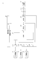
- FIG. 3 shows a detailed configuration of the vehicle interior side communication unit 201.
- cabin side communication portion 201 includes ports 211A, 211B, 211C, and 211D, cabin side receiver portion 221 , and communication portion 241 .
- Cabin-side receiving section 221 includes a distribution section 231 and a decoding section 232 .
- Each of the ports 211A, 211B, 211C, and 211D will also be referred to as a port 211 hereinafter.
- the distribution unit 231 and the decoding unit 232 are realized by processors such as CPU and DSP, for example.
- Communication unit 241 is realized by, for example, a communication IC.
- the port 211 is connectable with an in-vehicle device.
- the port 211 is, for example, a connector to which the cable of the on-vehicle device can be attached/detached.
- the radio vehicle unit 51 is connected to the port 211A
- the GPS vehicle unit 52 is connected to the port 211B
- the LTE vehicle unit 53 is connected to the port 211C
- the vehicle unit is connected to the port 211D.
- a user or administrator of vehicle 1 can add an on-board device to vehicle 1 by connecting the on-board device to port 211D after vehicle 1 is manufactured.
- a communication unit 241 in the vehicle interior side communication unit 201 is connected to the path unit 2 . More specifically, the communication section 241 is connected to the transmission path 3 in the path section 2 .
- the communication unit 241 receives the digital signal transmitted by the roof-side communication unit 101 from the transmission line 3 and outputs the received digital signal to the decoding unit 232 .
- the communication unit 241 receives an Ethernet frame containing a digital signal from the roof-side communication unit 101 via the transmission path 3, which is an Ethernet cable, and acquires the digital signal from the payload of the received Ethernet frame.
- the communication unit 241 receives the digital signal from the roof-side communication unit 101 via the transmission line 3, which is a USB cable.
- the decoding unit 232 performs error correction processing on the digital signal received from the communication unit 241 .
- the decoding unit 232 outputs the error-corrected digital signal to the distribution unit 231 .
- the distribution unit 231 separates the time-division multiplexed digital signal received from the decoding unit 232 for each vehicle-mounted device, and transmits the separated digital signal to the corresponding vehicle-mounted device.
- the distributing section 231 separates the digital signal in the frequency band assigned to the FM radio from the digital signal received from the decoding section 232 and transmits the digital signal to the radio vehicle-mounted device 51 via the port 211A. Also, the distribution unit 231 separates the digital signal in the frequency band assigned to GPS from the digital signal received from the decoding unit 232 and transmits the digital signal to the GPS vehicle-mounted device 52 via the port 211B. Also, the distributing unit 231 separates the digital signal in the frequency band assigned to LTE from the digital signal received from the decoding unit 232 and transmits the digital signal to the LTE vehicle-mounted device 53 via the port 211C.
- the radio vehicle-mounted device 51 performs processing for reproducing FM radio based on the digital signal received from the vehicle interior side communication unit 201 .
- the GPS onboard device 52 calculates the current position of the vehicle 1 based on the digital signal received from the vehicle interior side communication unit 201, and transmits the calculated current position to the car navigation system mounted on the vehicle 1, for example. do.
- the LTE vehicle-mounted device 53 performs processing for reproducing Internet content such as moving images based on the digital signal received from the vehicle interior side communication unit 201 .
- Each device in the vehicle-mounted transmission system includes a computer including a memory, and an arithmetic processing unit such as a CPU in the computer executes a program including part or all of each step of the following sequence. Read from memory and execute. Programs for these multiple devices can each be installed from the outside. Programs for these devices are stored in recording media and distributed.
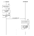
- FIG. 4 is a diagram showing an example of a sequence of transmission processing in the vehicle-mounted transmission system according to the first embodiment of the present disclosure.
- roof-side communication unit 101 receives RF signals from a plurality of wireless devices (step S102).
- the roof-side communication unit 101 generates a digital signal based on each received RF signal (step S104).
- the roof-side communication unit 101 performs error correction coding processing on the generated digital signal (step S106).
- the roof-side communication unit 101 transmits the error-correction-encoded digital signal to the passenger compartment-side communication unit 201 via the transmission line 3 (step S108).
- the passenger compartment side communication section 201 receives the digital signal from the roof side communication section 101 via the transmission path 3, and performs error correction processing on the received digital signal (step S110).
- the passenger compartment side communication unit 201 separates the error-corrected digital signal for each vehicle-mounted device and transmits it to the corresponding vehicle-mounted device (step S112).
- FIG. 5 is a diagram showing the configuration of an in-vehicle transmission system according to a modification of the first embodiment of the present disclosure.
- FIG. 5 shows a detailed configuration of the roof-side communication section 102.
- in-vehicle transmission system 302 includes roof-side communication section 102 instead of roof-side communication section 101 and vehicle-compartment-side communication section 201 instead of vehicle-side communication section 201 .
- a unit 202 is provided.
- the roof-side communication unit 102 includes a roof-side reception unit 122 instead of the roof-side reception unit 121, unlike the roof-side communication unit 101.
- roof-side receiving section 122 includes synthesizing section 151, sample hold circuit 152, AD converting section 153 and demodulating section 154 instead of AD converting section 131, demodulating section 132 and synthesizing section 133.
- the sample and hold circuit 152 has a switch 152A and a capacitor 152B.
- Synthesizer 151, demodulator 154, and encoder 134 are implemented by a processor such as a CPU and DSP, for example.
- Sample hold circuit 152 and AD converter 153 are realized by an IC, for example.
- a first end of the capacitor 152B in the sample hold circuit 152 is connected to a node N1 between the switch 152A and the AD converter 153, and a second end of the capacitor 152B is grounded.
- the switch 152A and the AD converter 153 in the sample hold circuit 152 operate using a common clock.
- the radio 21 is connected to port 111A
- the GPS radio 22 is connected to port 111B
- the LTE radio 23 is connected to port 111C
- the radio is connected to port 111D. do not have.
- the radio radio 21, GPS radio 22 and LTE radio 23 have antennas.
- the radio transceiver 21 receives an RF signal in the frequency band assigned to FM radio via an antenna and transmits the RF signal to the roof-side communication section 101 .
- GPS radio 12 receives an RF signal in the frequency band assigned to GPS via an antenna and transmits the RF signal to roof-side communication unit 101 .
- the LTE radio device 13 receives an RF signal in the frequency band assigned to LTE and transmits it to the roof-side communication unit 101 .
- the synthesizing unit 151 is provided between the transmission line 3 in the path unit 2 and the wireless device connected to the port 111 .
- Synthesizing unit 151 synthesizes RF signals from a plurality of wireless devices each connected to corresponding port 111 . More specifically, the synthesizing unit 151 multiplexes the RF signals received from the radio transceiver 21 , the GPS wireless device 22 and the LTE wireless device 23 via the corresponding port 111 and outputs them to the sample hold circuit 152 .
- the sample hold circuit 152 receives the RF signal multiplexed by the combining section 151 .
- Switch 152A in sample hold circuit 152 does not connect synthesizing section 151 and AD converting section 153 in the off state, but connects synthesizing section 151 and AD converting section 153 in the on state.
- Switch 152 A converts the RF signal received from synthesizing section 151 into an IF-band analog signal and outputs the analog signal to AD converting section 153 by switching between the ON state and the OFF state according to clock timing.
- Capacitor 152B removes high frequency components contained in the analog signal output from switch 152A.
- the AD converter 153 AD converts the analog signal that has passed through the switch 152A in the sample hold circuit 152 to generate a digital signal. More specifically, AD conversion section 153 converts the analog signal received from synthesis section 151 through sample hold circuit 152 into a digital signal and outputs the digital signal to demodulation section 154 .
- the demodulator 154 orthogonally demodulates the digital signal received from the AD converter 153 and outputs the demodulated digital signal to the encoder 134 .
- the encoding unit 134 performs error correction encoding processing on the digital signal received from the demodulation unit 154 .
- the encoding unit 134 outputs the digital signal subjected to error correction encoding processing to the communication unit 141 .
- the communication unit 141 transmits the digital signal received from the encoding unit 134 to the transmission line 3.
- the communication unit 141 transmits the digital signal to the transmission path 3, which is a USB cable.
- FIG. 6 is a diagram showing the configuration of an in-vehicle transmission system according to a modification of the first embodiment of the present disclosure.
- FIG. 6 shows a detailed configuration of the vehicle compartment side communication section 202.
- cabin-side communication unit 202 includes cabin-side reception unit 222 instead of cabin-side reception unit 221 , unlike cabin-side communication unit 201 .
- Cabin-side receiving section 222 includes distributing section 231A instead of distributing section 231, unlike cabin-side receiving section 221. As shown in FIG.
- the distribution unit 231A has a digital filter.
- the distribution unit 231A filters the digital signal received from the decoding unit 232, distributes the digital signal for each frequency band, and transmits it to the corresponding vehicle-mounted device.
- the distributing unit 231A extracts the digital signal in the frequency band assigned to the FM radio from the digital signal received from the decoding unit 232, and transmits the extracted digital signal to the radio vehicle unit 51 via the port 211A. Further, the distribution unit 231A extracts a digital signal in the frequency band assigned to GPS from the digital signal received from the decoding unit 232, and transmits the extracted digital signal to the GPS vehicle-mounted device 52 via the port 211B. Further, the distributing unit 231A extracts a digital signal in the frequency band assigned to LTE from the digital signal received from the decoding unit 232, and transmits the extracted digital signal to the LTE vehicle-mounted device 53 via the port 211C.
- the roof-side communication units 101 and 102 are configured to include the port 111, but are not limited to this.
- the roof-side communication units 101 and 102 may be configured without the port 111 .
- the radio is fixedly connected to the roof-side receivers 121 and 122, for example.
- the vehicle interior side communication units 201 and 202 are configured to include the port 211, but are not limited to this.
- the vehicle interior side communication units 201 and 202 may be configured without the port 211 .
- the in-vehicle device is fixedly connected to, for example, the passenger compartment side receiving units 221 and 222 .
- the roof-side reception units 121 and 122 in the roof-side communication units 101 and 102 are configured to include the encoding unit 134. , but not limited to.
- the roof-side receivers 121 and 122 may be configured without the encoder 134 .
- the communication unit 141 in the roof-side communication units 101 and 102 transmits digital signals that have not been subjected to error correction encoding processing to the passenger compartment-side communication units 201 and 202 via the transmission path 3 .
- the radio transceivers 11 and 21 are connected to the port 111A, and the GPS transceiver 12 is connected to the port 111B. , 22 are connected, and the LTE radios 13 and 23 are connected to the port 111C, but the present invention is not limited to this. Radios other than radio radios 11 and 21 , GPS radios 12 and 22 and LTE radios 13 and 23 may be connected to port 111 .
- the roof-side communication units 101 and 102 may be configured to receive RF signals corresponding to a plurality of services or analog signals in the IF band based on the RF signals from one wireless device.
- the transmission line connecting the roof-side communication unit and the passenger compartment-side communication unit is routed, for example, through a pillar of the vehicle 1 .
- the roof-side communication units 101 and 102 receive RF signals from a plurality of wireless devices corresponding to a plurality of frequency bands different from each other. , and transmits a digital signal based on each received RF signal to one transmission line 3 .
- the vehicle interior side communication unit 201 processes the digital signal received from the transmission line 3 for each frequency band.
- the roof-side communication units 101 and 102 transmit digital signals based on the RF signals received from a plurality of wireless devices to one transmission line 3, and the passenger compartment-side communication units 201 and 202 receive the digital signals from the transmission line 3.
- the digital signal for each frequency band transmission lines between the roof-side communication units 101 and 102 and the passenger compartment-side communication units 201 and 202 can be saved.
- digital signals are distributed to each frequency band by digital signal processing in the passenger compartment-side communication units 201 and 202.
- the present embodiment is different from the vehicle-mounted transmission system 301 in that instead of transmitting a digital signal from the roof-side communication unit to the vehicle-interior communication unit, It relates to an in-vehicle transmission system 303 that transmits a digital signal to the unit. It is the same as the in-vehicle transmission system 301 according to the first embodiment except for the contents described below.
- the in-vehicle transmission system 303 includes a passenger compartment side communication section 203 and a roof side communication section 103, which will be described later.
- the cabin-side communication unit 203 generates a digital signal including a plurality of data corresponding to a plurality of frequency bands different from each other, and transmits the generated digital signal to one transmission line 3 .
- the roof-side communication unit 103 distributes the digital signal received from the transmission line 3 or a signal based on the digital signal received from the transmission line 3 to a plurality of wireless devices corresponding to a plurality of frequency bands.
- FIG. 7 is a diagram showing the configuration of an in-vehicle transmission system according to the second embodiment of the present disclosure.
- FIG. 7 shows a detailed configuration of the vehicle interior communication section 203.
- cabin side communication unit 203 includes port 211 , cabin side transmission unit 223 and communication unit 242 .
- Cabin-side transmitter 223 includes modulators 251 A, 251 B, 251 C, and 251 D, a combiner 252 , and an encoder 253 .
- Each of the modulating sections 251A, 251B, 251C, and 251D will also be referred to as a modulating section 251 hereinafter.
- the modulation unit 251, the synthesis unit 252 and the encoding unit 253 are realized by processors such as a CPU and a DSP, for example.
- Communication unit 242 is realized by, for example, a communication IC.
- the communication unit 242 in the passenger compartment side communication unit 203 is connected to the path unit 2. More specifically, the communication section 242 is connected to the transmission path 3 in the path section 2 .
- an ETC (Electronic Toll Collection System) in-vehicle device 54 is connected to the port 211A
- an ITS (Intelligent Transport Systems) in-vehicle device 55 is connected to the port 211B
- an LTE in-vehicle device 53 is connected to the port 211C.
- port 211D is not connected to the vehicle-mounted device.
- the ETC vehicle-mounted device 54, the ITS vehicle-mounted device 55, and the LTE vehicle-mounted device 53 generate data corresponding to different frequency bands and transmit the data to the vehicle interior side communication unit 203. More specifically, the ETC vehicle-mounted device 54 generates data to be wirelessly transmitted by including it in the RF signal of the frequency band assigned to ETC, and transmits the generated data to the vehicle interior side communication unit 203 .
- the ITS vehicle-mounted device 55 generates data to be included in the RF signal of the frequency band assigned to the ITS to be wirelessly transmitted, and transmits the generated data to the vehicle interior side communication unit 203 .
- the LTE vehicle-mounted device 53 generates data to be included in the RF signal of the frequency band assigned to LTE and should be wirelessly transmitted, and transmits the generated data to the passenger compartment side communication unit 203 .
- Modulation unit 251 in cabin-side transmission unit 223 performs various signal processing such as quadrature modulation on the data received from the vehicle-mounted device via corresponding port 211, and synthesizes a digital signal including the processed data into synthesis unit 252.
- the modulation section 251A outputs to the synthesis section 252 a digital signal generated by performing various signal processing on the data received from the ETC vehicle-mounted device 54 via the port 211A.
- the modulation section 251B outputs to the synthesis section 252 a digital signal generated by performing various signal processing on the data received from the ITS on-board device 55 via the port 211B.
- the modulation unit 251C outputs to the combining unit 252 a digital signal generated by performing various signal processing on the data received from the LTE vehicle-mounted device 53 via the port 211C.
- the synthesizing unit 252 synthesizes digital signals based on data from a plurality of vehicle-mounted devices each connected to a corresponding port 211 . More specifically, synthesizing section 252 time-division multiplexes the digital signals received from modulating sections 251A, 251B, and 251C, for example. Synthesizing section 252 outputs the multiplexed digital signal to encoding section 253 .
- the encoding unit 253 performs error correction encoding processing on the digital signal received from the synthesizing unit 252 .
- the encoding unit 253 outputs the digital signal subjected to error correction encoding processing to the communication unit 242 .
- the communication unit 242 transmits the digital signal received from the encoding unit 253 to the transmission line 3.
- the communication unit 242 generates an Ethernet frame in which the digital signal is stored in the payload, and transmits the generated Ethernet frame to the roof side communication unit 103 via the transmission path 3, which is an Ethernet cable.
- the communication unit 242 transmits the digital signal to the roof-side communication unit 103 via the transmission line 3, which is a USB cable.
- the communication quality in the in-vehicle transmission system 303 can be improved by the configuration in which the vehicle interior side communication section 203 transmits the error correction encoded digital signal to the roof side communication section 103 via the transmission line 3. can.
- the required communication quality can be achieved. can be realized.
- the encoding rate of error correction encoding processing in the encoding unit 253 can be changed.
- the communication quality of the in-vehicle transmission system 303 may deteriorate due to deterioration of the transmission line 3 over time.
- the administrator of the in-vehicle transmission system 303 periodically or irregularly changes the setting of the coding rate of the error correction coding processing in the coding section 253 according to the years of use of the transmission line 3 .
- the communication quality required by the in-vehicle transmission system 303 can be stably achieved.
- FIG. 8 is a diagram showing the configuration of an in-vehicle transmission system according to the second embodiment of the present disclosure.
- FIG. 8 shows a detailed configuration of the roof-side communication section 103.
- roof-side communication unit 103 includes port 111 , roof-side transmission unit 123 and communication unit 142 .
- Roof-side transmission section 123 includes DA conversion sections 161A, 161B, 161C, and 161D, a distribution section 162, and a decoding section 163.
- Each of the DA converters 161A, 161B, 161C, and 161D is also referred to as a DA converter 161 hereinafter.
- DA converter 161 is realized by an IC, for example.
- Distribution section 162 and decoding section 163 are realized by a processor such as a CPU and a DSP, for example.
- Communication unit 142 is realized by, for example, a communication IC.
- the ETC radio 14 is connected to port 111A
- the ITS radio 15 is connected to port 111B
- the LTE radio 13 is connected to port 111C
- the radio is connected to port 111D. do not have.
- the ETC radio 14, ITS radio 15 and LTE radio 13 have antennas and radio transmission circuits (not shown).
- the radio transmission circuit includes a no-noise amplifier, a mixer, and a low-pass filter.
- the communication unit 142 in the roof-side communication unit 103 is connected to the route unit 2. More specifically, the communication unit 142 is connected to the transmission line 3 . Communication unit 142 receives the digital signal transmitted by vehicle interior communication unit 203 from transmission line 3 and outputs the received digital signal to decoding unit 163 . As an example, the communication unit 142 receives an Ethernet frame containing a digital signal from the vehicle interior communication unit 203 via the transmission line 3, which is an Ethernet cable, and acquires the digital signal from the payload of the received Ethernet frame. As another example, the communication unit 142 receives the digital signal from the vehicle interior communication unit 203 via the transmission line 3, which is a USB cable.
- the decoding unit 163 performs error correction processing on the digital signal received from the communication unit 142 .
- Decoding section 163 outputs the error-corrected digital signal to distributing section 162 .
- the distribution unit 162 is provided between the transmission line 3 in the path unit 2 and the wireless device connected to the port 111 .
- the distribution unit 162 distributes the digital signal from the transmission line 3 to the multiple ports 111 . More specifically, distribution section 162 separates the time-division multiplexed digital signal received from decoding section 163 for each wireless device, and outputs the separated digital signal to corresponding DA conversion section 161 .
- the distribution unit 162 may be configured by an Ethernet switch or a USB hub.
- the DA conversion section 161 converts the digital signal received from the distribution section 162 into an analog signal and transmits the analog signal to the wireless device via the corresponding port 111 . More specifically, the DA converter 161A converts the digital signal received from the distributor 162 into an analog signal and transmits the analog signal to the ETC radio 14 via the port 111A. The DA converter 161B converts the digital signal received from the distributor 162 into an analog signal and transmits the analog signal to the ITS radio device 15 via the port 111B. The DA conversion unit 161C converts the digital signal received from the distribution unit 162 into an analog signal, and transmits the analog signal to the LTE radio device 13 via the port 111C.
- the ETC radio 14 generates an RF signal in the frequency band assigned to ETC from the analog signal received from the roof-side communication unit 103 using a filter, an amplifier, etc., and transmits the generated RF signal via an antenna.
- the ITS radio 15 generates an RF signal in the frequency band assigned to the ITS from the analog signal received from the roof-side communication unit 103 using a filter, an amplifier, etc., and transmits the generated RF signal via an antenna.
- LTE radio device 13 generates an RF signal in the frequency band assigned to LTE from the analog signal received from roof-side communication unit 103 using a filter, an amplifier, and the like, and transmits the generated RF signal via an antenna.
- FIG. 9 is a diagram showing an example of a sequence of transmission processing in the vehicle-mounted transmission system according to the second embodiment of the present disclosure.
- vehicle interior side communication unit 203 receives data from a plurality of vehicle-mounted devices (step S202).
- the vehicle interior side communication unit 203 generates a digital signal based on each received data (step S204).
- the passenger compartment side communication unit 203 performs error correction coding processing on the generated digital signal (step S206).
- the passenger compartment side communication section 203 transmits the error correction encoded digital signal to the roof side communication section 103 via the transmission path 3 (step S208).
- the roof-side communication unit 103 receives the digital signal from the passenger compartment-side communication unit 203 via the transmission line 3, and performs error correction processing on the received digital signal (step S210).
- the roof-side communication unit 103 distributes the error-corrected digital signals, converts the distributed digital signals into analog signals, and transmits the analog signals to the plurality of wireless devices (step S212).
- FIG. 10 is a diagram showing the configuration of an in-vehicle transmission system according to a modification of the second embodiment of the present disclosure.
- FIG. 10 shows a detailed configuration of the vehicle compartment side communication section 204.
- vehicle-mounted transmission system 304 includes vehicle-room-side communication unit 204 instead of vehicle-room-side communication unit 203 , and roof-side communication unit 103 instead of roof-side communication unit 203 .
- a unit 104 is provided.
- the vehicle interior side communication section 204 includes a vehicle interior side transmission section 224 instead of the vehicle interior side transmission section 223 compared to the vehicle interior side communication section 203 .
- Cabin-side transmitter 224 includes delta-sigma modulators 261A, 261B, 261C, and 261D instead of encoder 253, unlike cabin-side transmitter 223.
- Each of the delta-sigma modulation sections 261A, 261B, 261C, and 261D is also referred to as the delta-sigma modulation section 261 below.
- Modulator 251, combiner 252, and delta-sigma modulator 261 are realized by processors such as CPU and DSP, for example.
- the cabin-side transmission unit 224 is an example of a so-called software-defined radio communication device.
- the vehicle interior side transmission unit 224 for example, non-patent document 1 (Takashi Maehata, three others, "SEI Technical Review January 2013 issue No. 182 Development of 1-bit digital RF radio equipment", Sumitomo Electric Industries, Ltd., January 2013, pp. 90-94) has the same function as the 1-bit digital radio device described.
- the modulating unit 251 in the cabin-side transmitting unit 224 performs various signal processing such as quadrature modulation on the data received from the vehicle-mounted device via the corresponding port 211, and converts the processed data into a digital signal.
- the signal is output to the corresponding delta-sigma modulation section 261 .
- the modulation section 251A outputs a digital signal generated by performing various signal processing on the data received from the ETC vehicle-mounted device 54 via the port 211A to the delta-sigma modulation section 261A.
- the modulation section 251B outputs a digital signal generated by performing various signal processing on the data received from the ITS vehicle-mounted device 55 via the port 211B to the delta-sigma modulation section 261B.
- the modulation unit 251C outputs a digital signal generated by performing various signal processing on the data received from the LTE vehicle-mounted device 53 via the port 211C to the delta-sigma modulation unit 261C.
- the delta-sigma modulation unit 261 performs delta-sigma modulation on the digital signal received from the corresponding modulation unit 251 to generate a 1-bit width digital signal as an RF signal.
- This RF signal has a spectrum in the frequency band corresponding to the vehicle-mounted device, and the noise level in other bands is equivalent to the level of the spectrum. In this RF signal, amplitude and phase information appear as sparse and dense bit strings on the time axis.
- the delta-sigma modulating section 261 outputs the generated RF signal to the synthesizing section 252 .
- the synthesizing unit 252 time-division multiplexes the RF signals received from the delta-sigma modulating units 261A, 261B, and 261C, for example.
- the combiner 252 outputs the multiplexed RF signal to the communication unit 242 .
- the communication unit 242 transmits the RF signal received from the combining unit 252 to the transmission line 3 as a digital signal.
- FIG. 11 is a diagram showing the configuration of an in-vehicle transmission system according to a modification of the second embodiment of the present disclosure.
- FIG. 11 shows a detailed configuration of the roof-side communication section 104.
- roof-side communication section 104 includes roof-side transmission section 124 instead of roof-side transmission section 123 , unlike roof-side communication section 103 .
- Roof-side transmitter 124 does not include decoder 163 and DA converter 161 unlike roof-side transmitter 123 .
- the communication unit 142 receives the RF signal transmitted by the passenger compartment side communication unit 204 from the transmission path 3 and outputs the received RF signal to the distribution unit 162 .
- the distribution unit 162 distributes the digital signal from the transmission line 3 to the multiple ports 111 .
- the distribution unit 162 separates the time-division multiplexed RF signal received from the communication unit 142 for each wireless device, and outputs the separated RF signals to the wireless device via the corresponding port 111 .
- the ETC radio 34 amplifies the RF signal received from the roof-side communication unit 104 using an amplifier, for example, and transmits it via the antenna.
- ITS radio device 15 amplifies the RF signal received from roof-side communication unit 104 using an amplifier, for example, and transmits the amplified signal via an antenna.
- LTE radio device 13 amplifies the RF signal received from roof-side communication unit 104 using an amplifier, for example, and transmits the amplified signal via an antenna.
- the distribution unit 162 may be configured to branch the time-division multiplexed RF signal received from the communication unit 142 and output to each port 111 .
- each wireless device extracts an RF signal in its own assigned frequency band from the RF signal received from the roof-side communication unit 104, amplifies the extracted RF signal, and transmits the amplified RF signal via the antenna.
- the ETC radio 34 extracts an RF signal in a frequency band assigned to ETC from the RF signal received from the roof-side communication unit 104, amplifies the extracted RF signal, and transmits it via an antenna. .
- the ITS radio 15 extracts an RF signal in the frequency band assigned to the ITS from the RF signal received from the roof-side communication unit 104, amplifies the extracted RF signal, and transmits the amplified RF signal via an antenna.
- the LTE radio device 13 extracts an RF signal in a frequency band assigned to LTE from the RF signal received from the roof-side communication unit 104, amplifies the extracted RF signal, and transmits the amplified RF signal via an antenna.
- the cabin-side transmission unit 223 in the cabin-side communication unit 203 is configured to include the encoding unit 253. not something to do.
- the cabin-side transmitter 223 may be configured without the encoder 253 .
- the communication unit 242 in the passenger compartment side communication unit 203 transmits a digital signal that has not undergone error correction encoding processing to the roof side communication unit 103 via the transmission line 3 .
- the delta-sigma modulation unit 261 is provided in the cabin side transmission unit 224 in the cabin side communication unit 204.
- the delta-sigma modulation section 261 may be provided in the roof side transmission section 124 in the roof side communication section 104 instead of being provided in the passenger compartment side transmission section 224 .
- communication unit 242 in passenger compartment side communication unit 204 receives the digital signal from synthesis unit 252 and transmits the received digital signal to roof side communication unit 104 via transmission path 3 .
- the communication unit 142 in the roof side communication unit 104 outputs the digital signal received via the transmission path 3 to the delta-sigma modulation unit 261 .
- the delta-sigma modulation unit 261 generates a 1-bit width digital signal as an RF signal by performing delta-sigma modulation on the digital signal received from the communication unit 142, and transmits the generated RF signal via the corresponding port 111. Send to radio.
- the transmission line connecting the roof-side communication unit and the passenger compartment-side communication unit is routed, for example, through a pillar of the vehicle 1 .
- the vehicle interior side communication units 202 and 203 each include a plurality of data corresponding to a plurality of frequency bands different from each other.
- a signal is generated and the generated digital signal is transmitted to one transmission line 3 .
- the roof-side communication units 103 and 104 distribute the digital signal received from the transmission line 3, and transmit the distributed digital signal or a signal based on the distributed digital signal to a plurality of wireless devices respectively corresponding to a plurality of frequency bands. .
- the passenger compartment side communication units 203 and 204 generate digital signals containing a plurality of data corresponding to a plurality of frequency bands different from each other, transmit them to one transmission path 3, and transmit them to the roof side communication units 103 and 104.
- the roof side communication unit 103 , 104 and the vehicle interior side communication units 203 and 204 can be saved.
- the roof side communication units 103 and 104 distribute the digital signals for each frequency band by digital signal processing. Therefore, digital signals based on data received from a plurality of vehicle-mounted devices can be distributed by frequency band with a simple and inexpensive configuration and transmitted to the wireless devices.
- signal loss in the transmission line 3 can be suppressed, so transmission quality can be improved. can be done.
- the present embodiment transmits a digital signal from the roof-side communication unit to the passenger compartment-side communication unit. It relates to an in-vehicle transmission system 305 that transmits a digital signal to a side communication unit. It is the same as the in-vehicle transmission system 301 according to the first embodiment except for the contents described below.
- FIG. 12 is a diagram showing the configuration of an in-vehicle transmission system according to the third embodiment of the present disclosure.
- in-vehicle transmission system 305 includes passenger compartment side communication section 205 and roof side communication section 105 .
- the roof-side communication unit 105 receives RF signals from a plurality of wireless devices corresponding to a plurality of frequency bands different from each other, and transmits digital signals based on the received RF signals to one transmission line in the path unit 2.
- Interior communication section 205 processes the digital signal received from the transmission line in path section 2 for each frequency band.
- the passenger compartment side communication unit 205 generates a digital signal including a plurality of data corresponding to a plurality of frequency bands different from each other, and transmits the generated digital signal to one transmission line 3 .
- the roof-side communication unit 105 distributes the digital signal received from the transmission line 3, and transmits the distributed digital signal or a signal based on the distributed digital signal to a plurality of wireless devices respectively corresponding to a plurality of frequency bands.
- the roof-side communication section 105 includes a port 111 , a roof-side reception section 121 , a roof-side transmission section 123 and a communication section 143 .
- Interior communication section 205 includes port 211 , interior reception section 221 , interior transmission section 223 , and communication section 243 .
- a communication unit 143 in the roof-side communication unit 105 receives from the roof-side reception unit 121 digital signals based on RF signals from a plurality of wireless devices, and transmits the received digital signals to the transmission line 3 .
- the communication section 243 in the vehicle interior side communication section 205 receives the digital signal transmitted by the roof side communication section 105 from the transmission line 3 and outputs the received digital signal to the vehicle interior side reception section 221 .
- the communication unit 243 in the passenger compartment side communication unit 205 receives digital signals based on data from a plurality of vehicle-mounted devices from the passenger compartment side transmission unit 223 and transmits the received digital signals to the transmission path 3 .
- the communication unit 143 in the roof-side communication unit 105 receives the digital signal transmitted by the passenger compartment-side communication unit 205 from the transmission path 3 and outputs the received digital signal to the roof-side transmission unit 123 .
- the digital signal transmitted from the vehicle compartment side communication section 205 to the roof side communication section 105 is also referred to as an upstream digital signal
- the digital signal transmitted from the roof side communication section 105 to the vehicle compartment side communication section 205 is also referred to as a downstream digital signal. called.
- the communication unit 143 and the communication unit 243 transmit and receive digital signals through full-duplex communication by performing time-division duplex or the like via the transmission path 3 .
- the communication unit 143 and the communication unit 243 may be configured to transmit and receive digital signals via the transmission path 3 by half-duplex communication.
- the path unit 2 includes two transmission lines 3
- the communication unit 143 and the communication unit 243 transmit an upstream digital signal using one of the transmission lines 3, and transmit a downstream digital signal using the other transmission line 3.
- a configuration may be employed in which digital signals are transmitted and received by full-duplex communication by transmitting signals.
- the roof-side communication unit 105 may include the roof-side reception unit 122 instead of the roof-side reception unit 121, or the roof-side reception unit 122 may be provided.
- a configuration including a roof-side transmitter 124 instead of the side transmitter 123 may be employed.
- the vehicle interior communication unit 205 may be configured to include the vehicle interior reception unit 222 instead of the vehicle interior reception unit 221.
- the vehicle interior side transmission section 224 may be provided instead of the vehicle interior side transmission section 223 .
- a roof-side communication unit that receives RF signals from a plurality of wireless devices corresponding to a plurality of frequency bands that are different from each other, and transmits digital signals based on the received RF signals to one transmission line; a vehicle interior side communication unit that processes the digital signal received from the transmission line for each frequency band, The vehicle interior side communication unit generates a digital signal including a plurality of data corresponding to a plurality of frequency bands different from each other, transmits the generated digital signal to one transmission line, In-vehicle transmission, wherein the roof-side communication unit distributes the digital signal received from the transmission line or a signal based on the digital signal received from the transmission line to a plurality of wireless devices corresponding to the plurality of frequency bands. system.
Landscapes
- Engineering & Computer Science (AREA)
- Computer Networks & Wireless Communication (AREA)
- Signal Processing (AREA)
- Transceivers (AREA)
- Details Of Aerials (AREA)
- Input Circuits Of Receivers And Coupling Of Receivers And Audio Equipment (AREA)
- Mobile Radio Communication Systems (AREA)
Priority Applications (2)
| Application Number | Priority Date | Filing Date | Title |
|---|---|---|---|
| CN202280020208.2A CN117015934A (zh) | 2021-03-12 | 2022-03-10 | 车载传输系统 |
| US18/549,523 US20240154637A1 (en) | 2021-03-12 | 2022-03-10 | Onboard transmission system |
Applications Claiming Priority (2)
| Application Number | Priority Date | Filing Date | Title |
|---|---|---|---|
| JP2021039803A JP2022139423A (ja) | 2021-03-12 | 2021-03-12 | 車載伝送システム |
| JP2021-039803 | 2021-03-12 |
Publications (1)
| Publication Number | Publication Date |
|---|---|
| WO2022191282A1 true WO2022191282A1 (ja) | 2022-09-15 |
Family
ID=83228082
Family Applications (1)
| Application Number | Title | Priority Date | Filing Date |
|---|---|---|---|
| PCT/JP2022/010569 Ceased WO2022191282A1 (ja) | 2021-03-12 | 2022-03-10 | 車載伝送システム |
Country Status (4)
| Country | Link |
|---|---|
| US (1) | US20240154637A1 (enExample) |
| JP (1) | JP2022139423A (enExample) |
| CN (1) | CN117015934A (enExample) |
| WO (1) | WO2022191282A1 (enExample) |
Citations (4)
| Publication number | Priority date | Publication date | Assignee | Title |
|---|---|---|---|---|
| JP2001136235A (ja) * | 1999-11-05 | 2001-05-18 | Matsushita Electric Ind Co Ltd | 移動体通信端末装置 |
| WO2019087441A1 (ja) * | 2017-11-06 | 2019-05-09 | 住友電気工業株式会社 | 車載伝送システム |
| JP2020102818A (ja) * | 2018-12-25 | 2020-07-02 | 住友電気工業株式会社 | 車載伝送システム |
| WO2020137929A1 (ja) * | 2018-12-25 | 2020-07-02 | 住友電気工業株式会社 | 車載伝送システム |
-
2021
- 2021-03-12 JP JP2021039803A patent/JP2022139423A/ja active Pending
-
2022
- 2022-03-10 CN CN202280020208.2A patent/CN117015934A/zh active Pending
- 2022-03-10 US US18/549,523 patent/US20240154637A1/en active Pending
- 2022-03-10 WO PCT/JP2022/010569 patent/WO2022191282A1/ja not_active Ceased
Patent Citations (4)
| Publication number | Priority date | Publication date | Assignee | Title |
|---|---|---|---|---|
| JP2001136235A (ja) * | 1999-11-05 | 2001-05-18 | Matsushita Electric Ind Co Ltd | 移動体通信端末装置 |
| WO2019087441A1 (ja) * | 2017-11-06 | 2019-05-09 | 住友電気工業株式会社 | 車載伝送システム |
| JP2020102818A (ja) * | 2018-12-25 | 2020-07-02 | 住友電気工業株式会社 | 車載伝送システム |
| WO2020137929A1 (ja) * | 2018-12-25 | 2020-07-02 | 住友電気工業株式会社 | 車載伝送システム |
Also Published As
| Publication number | Publication date |
|---|---|
| CN117015934A (zh) | 2023-11-07 |
| US20240154637A1 (en) | 2024-05-09 |
| JP2022139423A (ja) | 2022-09-26 |
Similar Documents
| Publication | Publication Date | Title |
|---|---|---|
| CN111279620B (zh) | 车载传输系统 | |
| US10211855B2 (en) | Apparatus for multi carrier aggregation in a software defined radio | |
| EP1865611A2 (en) | Vehicle telematics satellite data transceiver utilizing FM radio circuitry | |
| CN108233954A (zh) | 用于混合δ-σ以及尼奎斯特数据转换器的方法和设备 | |
| CN113474218A (zh) | 车载用天线装置 | |
| WO2022191281A1 (ja) | 車載伝送システム | |
| CN115441933A (zh) | 一种软件定义星载通用通信系统 | |
| WO2022191282A1 (ja) | 車載伝送システム | |
| CN107968659A (zh) | 用于软件定义无线电中的联合均衡和噪声整形的方法和设备 | |
| JP7359161B2 (ja) | 車載伝送システム | |
| CN111060866B (zh) | 一种双通道无线通信测向系统及其测向方法 | |
| EP1056221A2 (en) | Integrated receiving system for receiving a plurality of media signals and corresponding signal reception processing method | |
| EP1686704A2 (en) | Vehicle-mounted receiving apparatus | |
| CN111886815B (zh) | 用于生成无线电信号接收选项的模块 | |
| JP2005026770A (ja) | 移動体搭載伝送装置 | |
| Budroweit | Software-defined radio with flexible RF front end for satellite maritime radio applications | |
| US8032100B2 (en) | System and method of communicating multiple carrier waves | |
| KR100872245B1 (ko) | 차량용 멀티미디어 시스템의 통합 안테나 제어 방법 | |
| WO2004110086A1 (en) | Frequency multiplexed architecture | |
| CN108242937B (zh) | 多速率的能量有效型Delta-sigma转换器 | |
| KR100962132B1 (ko) | 차량의 위성 방송 시스템 및 장치 | |
| WO2021090685A1 (ja) | 車載用無線システム | |
| JP5859141B2 (ja) | 受信機 | |
| JP2011040833A (ja) | 車載用デジタル放送受信システム | |
| JP2021064913A (ja) | 車載用受信システム |
Legal Events
| Date | Code | Title | Description |
|---|---|---|---|
| 121 | Ep: the epo has been informed by wipo that ep was designated in this application |
Ref document number: 22767236 Country of ref document: EP Kind code of ref document: A1 |
|
| DPE1 | Request for preliminary examination filed after expiration of 19th month from priority date (pct application filed from 20040101) | ||
| WWE | Wipo information: entry into national phase |
Ref document number: 18549523 Country of ref document: US |
|
| WWE | Wipo information: entry into national phase |
Ref document number: 202280020208.2 Country of ref document: CN |
|
| NENP | Non-entry into the national phase |
Ref country code: DE |
|
| 122 | Ep: pct application non-entry in european phase |
Ref document number: 22767236 Country of ref document: EP Kind code of ref document: A1 |