WO2022191255A1 - システム制御装置、ロボット制御方法、端末装置、端末制御方法、及びロボット制御システム - Google Patents
システム制御装置、ロボット制御方法、端末装置、端末制御方法、及びロボット制御システム Download PDFInfo
- Publication number
- WO2022191255A1 WO2022191255A1 PCT/JP2022/010405 JP2022010405W WO2022191255A1 WO 2022191255 A1 WO2022191255 A1 WO 2022191255A1 JP 2022010405 W JP2022010405 W JP 2022010405W WO 2022191255 A1 WO2022191255 A1 WO 2022191255A1
- Authority
- WO
- WIPO (PCT)
- Prior art keywords
- robot
- information
- control unit
- work
- library
- Prior art date
- Legal status (The legal status is an assumption and is not a legal conclusion. Google has not performed a legal analysis and makes no representation as to the accuracy of the status listed.)
- Ceased
Links
Images





Classifications
-
- B—PERFORMING OPERATIONS; TRANSPORTING
- B25—HAND TOOLS; PORTABLE POWER-DRIVEN TOOLS; MANIPULATORS
- B25J—MANIPULATORS; CHAMBERS PROVIDED WITH MANIPULATION DEVICES
- B25J9/00—Program-controlled manipulators
- B25J9/16—Program controls
- B25J9/1656—Program controls characterised by programming, planning systems for manipulators
- B25J9/1664—Program controls characterised by programming, planning systems for manipulators characterised by motion, path, trajectory planning
-
- B—PERFORMING OPERATIONS; TRANSPORTING
- B25—HAND TOOLS; PORTABLE POWER-DRIVEN TOOLS; MANIPULATORS
- B25J—MANIPULATORS; CHAMBERS PROVIDED WITH MANIPULATION DEVICES
- B25J9/00—Program-controlled manipulators
- B25J9/16—Program controls
- B25J9/1656—Program controls characterised by programming, planning systems for manipulators
- B25J9/1661—Program controls characterised by programming, planning systems for manipulators characterised by task planning, object-oriented languages
-
- B—PERFORMING OPERATIONS; TRANSPORTING
- B25—HAND TOOLS; PORTABLE POWER-DRIVEN TOOLS; MANIPULATORS
- B25J—MANIPULATORS; CHAMBERS PROVIDED WITH MANIPULATION DEVICES
- B25J9/00—Program-controlled manipulators
- B25J9/0081—Program-controlled manipulators with leader teach-in means
-
- B—PERFORMING OPERATIONS; TRANSPORTING
- B25—HAND TOOLS; PORTABLE POWER-DRIVEN TOOLS; MANIPULATORS
- B25J—MANIPULATORS; CHAMBERS PROVIDED WITH MANIPULATION DEVICES
- B25J9/00—Program-controlled manipulators
- B25J9/16—Program controls
- B25J9/1602—Program controls characterised by the control system, structure, architecture
- B25J9/161—Hardware, e.g. neural networks, fuzzy logic, interfaces, processor
-
- G—PHYSICS
- G05—CONTROLLING; REGULATING
- G05B—CONTROL OR REGULATING SYSTEMS IN GENERAL; FUNCTIONAL ELEMENTS OF SUCH SYSTEMS; MONITORING OR TESTING ARRANGEMENTS FOR SUCH SYSTEMS OR ELEMENTS
- G05B19/00—Program-control systems
- G05B19/02—Program-control systems electric
- G05B19/418—Total factory control, i.e. centrally controlling a plurality of machines, e.g. direct or distributed numerical control [DNC], flexible manufacturing systems [FMS], integrated manufacturing systems [IMS] or computer integrated manufacturing [CIM]
- G05B19/41865—Total factory control, i.e. centrally controlling a plurality of machines, e.g. direct or distributed numerical control [DNC], flexible manufacturing systems [FMS], integrated manufacturing systems [IMS] or computer integrated manufacturing [CIM] characterised by job scheduling, process planning, material flow
-
- G—PHYSICS
- G05—CONTROLLING; REGULATING
- G05B—CONTROL OR REGULATING SYSTEMS IN GENERAL; FUNCTIONAL ELEMENTS OF SUCH SYSTEMS; MONITORING OR TESTING ARRANGEMENTS FOR SUCH SYSTEMS OR ELEMENTS
- G05B19/00—Program-control systems
- G05B19/02—Program-control systems electric
- G05B19/18—Numerical control [NC], i.e. automatically operating machines, in particular machine tools, e.g. in a manufacturing environment, so as to execute positioning, movement or co-ordinated operations by means of program data in numerical form
- G05B19/4155—Numerical control [NC], i.e. automatically operating machines, in particular machine tools, e.g. in a manufacturing environment, so as to execute positioning, movement or co-ordinated operations by means of program data in numerical form characterised by program execution, i.e. part program or machine function execution, e.g. selection of a program
Definitions
- the present disclosure relates to a system control device, a robot control method, a terminal device, a terminal control method, and a robot control system.
- Patent Literature 1 describes a system control device that operates a robot by executing a program that drives and controls axes of various types of joints.
- a system control device includes a first interface, a second interface, and a control unit.
- the first interface is communicatively connected to a terminal device that receives user input.
- the second interface is communicable with a robot controller that controls at least one robot based on at least one library that defines actions and execution timings including at least one of start timing and end timing of the actions.
- connected to The control unit can communicate with the first interface and the second interface.
- the control unit acquires or generates, based on an input from the terminal device, schedule information capable of specifying the execution timing, which is related to the job information capable of specifying the at least one library.
- the control unit outputs to the robot control unit an instruction to cause the at least one robot to execute the operation specified by the job information at the execution timing specified by the schedule information.
- a robot control method includes communicating with a terminal device that accepts user input.
- the robot control method communicates with a robot controller that controls at least one robot based on at least one library defining motions and execution timings including at least one of start timing and end timing of the motions.
- the robot control method includes acquiring or generating, based on an input from the user, schedule information capable of specifying the execution timing, which is related to job information capable of specifying the library.
- the robot control method includes outputting to the robot control unit an instruction to cause the at least one robot to execute an operation specified by the job information at an execution timing specified by the schedule information.
- a terminal device includes a user interface, a communication interface, and a terminal control section.
- the user interface accepts input from a user.
- the communication interface outputs information to a robot controller that controls at least one robot based on at least one library that defines an action and execution timing that includes at least one of start timing and end timing of the action.
- the communication interface outputs the job information and the schedule information to the system controller.
- a terminal control method includes receiving input from a user.
- the terminal control method is related to job information capable of specifying the library based on at least one library defining an action and execution timing including at least one of start timing and end timing of the action. It includes generating and outputting schedule information that can specify execution timing.
- a robot control system includes a terminal device, a robot control section, and a system control device.
- the terminal device has a user interface that receives input from a user.
- the robot control unit controls at least one robot based on at least one library defining an action and execution timing including at least one of start timing and end timing of the action.
- the system controller is communicably connected to each of the robot controller and the terminal device.
- the terminal device generates schedule information capable of specifying the execution timing, related to job information capable of specifying the library, based on information input to the user interface specifying the work content to be executed by the robot. and output to the system controller.
- the system control device outputs to the robot control unit an instruction to cause the at least one robot to execute the work identifiable by the job information at an execution timing identifiable by the schedule information. Based on the instruction, the robot control unit calls the at least one library associated with the job information, thereby executing the at least one operation identifiable by the job information at a timing identifiable by the schedule information. Let the robot do it.
- FIG. 1 is a block diagram showing a configuration example of a robot control system according to an embodiment
- FIG. FIG. 4 is a block diagram showing another configuration example of the robot control system according to one embodiment
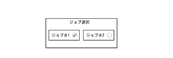
- FIG. 10 is a diagram showing an example of a job selection screen; It is a figure which shows an example of the selection screen of a robot.
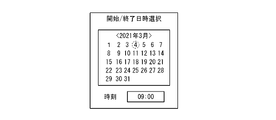
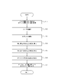
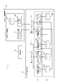
- FIG. 10 is a diagram showing an example of a selection screen for work execution start or execution end date and time; 4 is a flow chart showing an example of a procedure for realizing a schedule management function; It is a figure which shows an example of a software configuration.
- FIG. 10 is a diagram showing an example of a job selection screen; It is a figure which shows an example of the selection screen of a robot.
- FIG. 10 is a diagram showing an example of a selection screen for work execution start or execution end date and time
- 4 is a flow chart showing an example of a procedure for realizing a schedule management function
- It is a figure which shows an example of a software configuration.
- 4 is a sequence diagram showing an example of a procedure of a robot control method executed by the robot control system; 4 is a flow chart showing a procedure example of a robot control method executed by the system control device; 4 is a flow chart showing an example of a procedure of a terminal control method executed by a terminal device; 4 is a flow chart showing a procedure example of a robot control method executed by a robot control unit;
- a robot control system 1 includes a system control device 10 and a terminal device 20. As shown in FIG. The robot control system 1 further includes a robot control device 30 (see FIG. 2) that controls the robot 40, as will be described later.
- the system control device 10, the terminal device 20, and the robot 40 or the robot control device 30 are connected via a network 80 so as to be able to communicate with each other.
- the system control device 10 , the terminal device 20 , and the robot 40 or the robot control device 30 may be communicatively connected without the network 80 .
- the network 80 and the robot 40 or robot controller 30 may be communicatively connected via an access point 82 .
- the network 80 and the robot 40 or the robot controller 30 may be communicatively connected without going through the access point 82 .
- the number of system control devices 10 and terminal devices 20 is not limited to three as illustrated, and may be two or less, or may be four or more.
- the robot control system 1 accepts input of information specifying the work (movement) to be executed by the robot 40 from the user via the terminal device 20 .
- the robot control system 1 receives input of information specifying timings for starting and ending work of the robot 40 from the user through the terminal device 20 .
- the timing for causing the robot 40 to start work is also referred to as start timing.
- the timing for causing the robot 40 to finish (for example, stop) the work is also called an end timing.
- the start timing and end timing are collectively referred to as execution timing. In other words, the execution timing includes at least one of start timing and end timing.
- the system control device 10 acquires information specifying the timing of the start or end of execution of the work whose input is received from the terminal device 20 from the user, and manages the schedule of the work.
- the system control device 10 instructs the robot control device 30 to perform work to be performed by the robot 40 when the date and time determined by the schedule information managed by the system control device 10 come. output the information to The robot control system 1 causes the robot 40 to perform work by means of the robot control device 30 .
- the robot control system 1 can cause the robot 40 to perform work according to abstracted work instructions. Further, the robot control system 1 according to this embodiment can cause the robot 40 to perform work according to a predetermined schedule.
- the user can compose data indicating the content of the work to be executed by the robot 40 and instruct the robot 40 to execute the work, for example, through abstract settings from a GUI (Graphical User Interface).
- GUI Graphic User Interface
- the robot control system 1 according to the present embodiment defines and instructs which robot 40 is to do when, where, what, and how in an abstract granularity like work instructions executed between humans. You can
- a system that causes the robot 40 to perform the work by setting the operation of the robot 40 in detail by the user through teaching work can be considered.
- a teaching operation is required for each type of object to be transported or for each state.
- work instructions for the robot 40 can be given at an abstract granularity. Further, the robot control system 1 can cause the robot 40 to perform the instructed work based on the information specifying the date and time determined in the schedule in advance. As a result, the robot 40 can be used for more versatile purposes.
- the robot control system 1 further comprises a robot controller 30 that controls at least one robot 40 .
- the system control device 10 is communicably connected to each of the terminal device 20 and the robot control device 30 .
- the system control device 10 may be communicably connected to each of the terminal device 20 and the robot control device 30 via the network 80 .
- the system control device 10 includes a control section 11 , a first interface 13 and a second interface 14 .
- the control unit 11 can communicate with the first interface 13 and the second interface 14 .
- the control unit 11 is also called a system control unit.
- the system control device 10 is communicably connected to the terminal device 20 via the first interface 13 .
- the system controller 10 is communicatively connected to the robot controller 30 via the second interface 14 .
- the system control device 10 may be connected to each of the terminal device 20 and the robot control device 30 so as to be able to communicate by wire, or may be connected so as to be able to communicate wirelessly.
- the robot control device 30 and at least one robot 40 may be communicably connected by wire or may be communicatively connected by radio.
- Each component of the robot control system 1 may be communicatively connected via a wireless base station or access point 82 (see FIG. 1), or may be communicatively connected without the wireless base station or access point 82.
- the access point 82 refers to a wireless device for connecting terminals equipped with a wireless connection function to each other or to other networks. It is a device that operates on layer (physical layer) and layer 2 (data link layer) communication protocols.
- Each component of the robot control system 1 may be communicably connected via a dedicated line.
- Each component of the robot control system 1 is not limited to these examples, and may be communicably connected to each other in various other forms.
- the control unit 11 may include at least one processor to implement various functions or controls of the system control device 10 .
- the processor may execute programs that implement various functions of system controller 10 .
- a processor may be implemented as a single integrated circuit.
- An integrated circuit is also called an IC (Integrated Circuit).
- a processor may be implemented as a plurality of communicatively coupled integrated and discrete circuits.
- the processor may be configured including a CPU (Central Processing Unit).
- the processor may be configured including a DSP (Digital Signal Processor) or a GPU (Graphics Processing Unit). Processors may be implemented based on various other known technologies.
- the system control device 10 further includes a storage unit 12 .
- the storage unit 12 may be configured including an electromagnetic storage medium such as a magnetic disk, or may be configured including a memory such as a semiconductor memory or a magnetic memory.
- the storage unit 12 may be configured as an HDD (Hard Disk Drive) or an SSD (Solid State Drive).
- the storage unit 12 stores various information, programs executed by the control unit 11, and the like.
- the storage unit 12 may function as a work memory for the control unit 11 . At least part of the storage unit 12 may be included in the control unit 11 .
- the system control device 10 further comprises a scheduler 15.
- the scheduler 15 implements a schedule management function, which will be described later.
- a scheduler 15 is included in the control unit 11 .
- the scheduler 15 may be configured separately from the control unit 11 .
- the functions of the scheduler 15 may be implemented by the control unit 11 . If the functions of the scheduler 15 are realized by the control unit 11 , the system control device 10 does not have to include the scheduler 15 .
- the first interface 13 or the second interface 14 may be configured including a communication device configured to be capable of wired or wireless communication.
- a communication device may be configured to be able to communicate with communication schemes based on various communication standards.
- the first interface 13 or the second interface 14 can be configured by known communication technology. A detailed description of the hardware of the first interface 13 or the second interface 14 is omitted.
- the functions of the first interface 13 and the second interface 14 may be implemented by one interface, or may be implemented by separate interfaces.
- the system control device 10 may be communicably connected to the network 80 via the first interface 13 or the second interface 14 .
- the system control device 10 may be communicably connected to the terminal device 20 and the robot control device 30 via the network 80 .
- the first interface 13 communicates with the terminal device 20 .
- the second interface 14 communicates with the robot controller 30 .
- the system control device 10 may be configured as a server device.
- the server device may be configured including at least one information processing device.
- the server device may be configured to cause a plurality of information processing devices to execute parallel processing.
- the server device does not need to be configured including a physical enclosure, and may be configured based on virtualization technology such as a virtual machine or container orchestration system.
- the server device may be configured using a cloud service. When the server device is configured using cloud services, it can be configured by combining managed services. That is, the functions of the system control device 10 can be implemented as cloud services.
- the server device may comprise at least one server group and at least one database group.
- the server group functions as the control unit 11 .
- the database group functions as the storage unit 12 .
- the number of server groups may be one or two or more. When the number of server groups is one, functions realized by one server group include functions realized by each server group.
- Each server group is communicably connected to each other by wire or wirelessly.
- the number of database groups may be one or two or more. The number of database groups may be increased or decreased as appropriate based on the capacity of data managed by the server device and availability requirements for the server device.
- the database group is communicably connected to each server group by wire or wirelessly.
- system control device 10 is described as one configuration in FIGS. 1 and 2, multiple configurations can be regarded as one system and operated as necessary. That is, the system control device 10 is configured as a platform with variable capacity. By using a plurality of configurations as the system control device 10, even if one configuration becomes inoperable in the event of an unforeseen event such as a natural disaster, the other configurations are used to continue the operation of the system. In this case, each of the plurality of components is connected by a line, whether wired or wireless, and configured to be able to communicate with each other. These multiple configurations may be built across cloud services and on-premises environments.
- system control device 10 is connected to the terminal device 20, the robot control device 30, and the robot 40 controlled by the robot control device 30 through a line that may be wired or wireless.
- the system control device 10, the terminal device 20, and the robot control device 30 are provided with an interface using a standard protocol, and are capable of two-way communication.
- the terminal device 20 includes a terminal control section 21 , a communication interface 22 and a user interface 23 .
- the terminal control unit 21 may be configured including at least one processor.
- the terminal controller 21 may be configured identically or similarly to the controller 11 of the system controller 10 .
- the terminal control unit 21 may execute an application that provides a GUI (Graphical User Interface) corresponding to the user interface 23, which will be described later.
- the terminal control unit 21 may provide a GUI by executing a GUI program distributed from another device such as the system control device 10 on a web browser.
- the terminal control unit 21 receives a GUI program from another device such as the system control device 10 based on a request input to the web browser by the user, and executes the program on the web browser. may be configured to draw.
- the terminal device 20 may be installed in the on-premises environment, or may be constructed across the cloud service and the on-premises environment. That is, for example, the user interface 23 may be constructed in an on-premises environment, and the terminal control unit 21 may be constructed as a cloud service.
- the communication interface 22 may be configured identically or similarly to the first interface 13 or the second interface 14 of the system control device 10 .
- the user interface 23 is configured to provide the GUI described above to the user.
- the user interface 23 includes an output device that outputs information to the user and an input device that receives input from the user.
- the output device may be configured including a display device.
- the display device may include, for example, a liquid crystal display (LCD), an organic EL (Electro-Luminescence) display or an inorganic EL display, or a plasma display (PDP: Plasma Display Panel).
- the display device is not limited to these displays, and may be configured to include other various types of displays.
- the display device may include a light-emitting device such as an LED (Light Emitting Diode).
- the display device may be configured including other various devices.
- the output device may include an audio output device such as a speaker that outputs auditory information such as voice. Output devices are not limited to these examples, and may be configured to include other various devices.
- the input device may include, for example, a touch panel or touch sensor, or a pointing device such as a mouse.
- the input device may be configured including physical keys.
- the input device may include an audio input device such as a microphone. Input devices are not limited to these examples, and may be configured to include other various devices.
- the terminal device 20 may be configured including at least one information processing device.
- the number of terminal devices 20 included in the robot control system 1 is not limited to one, and may be two or more.
- each terminal device 20 may receive input from the user.
- the terminal device 20 may be configured as a tablet terminal.
- the terminal device 20 may be configured as a mobile phone terminal such as a feature phone or a smart phone.
- the terminal device 20 may be configured as a PC terminal such as a desktop PC (Personal Computer) or a notebook PC.
- the terminal device 20 is not limited to these examples, and may be configured as various devices capable of providing GUI and communication functions.
- the terminal device 20 may further include a storage unit.
- the storage unit of the terminal device 20 may be configured the same as or similar to the storage unit 12 of the system control device 10 .
- the terminal device 20 is used by the user to give work instructions to the robot control device 30 and the robot 40 via the system control device 10 .
- the terminal device 20 allows the user to register, delete, or change the operation start time and end time of a specific robot 40 with respect to the scheduler 15 included in the control unit 11 in the system control device 10 or the schedule management function of the control unit 11. can be executed.
- the terminal device 20 instructs addition or deletion of software in the library group 333 (see FIG. 5) that defines the motion of the robot 40, or changes the settings of the robot control system 1, for example, via a browser or a dedicated application. may be used for Terminal device 20 may be used to monitor the status of robot 40 .
- the terminal device 20 is not limited to these examples and can provide various other functions.
- the robot controller 30 includes a robot controller 31 .
- the robot controller 31 may include at least one processor to implement various functions or controls of the robot controller 30 .
- the robot controller 31 may be configured identically or similarly to the controller 11 of the system controller 10 .
- the robot control device 30 acquires from the system control device 10 job information and task information specifying the work to be executed by the robot 40 at the date and time predetermined by the system control device 10 in the schedule.
- Job information can specify a library.
- the task information corresponds to an instruction to cause at least one robot 40 to perform the task specified by the job information.
- the robot control device 30 outputs information specifying the motion of the robot 40 based on the job information and task information.
- the work performed by the robot 40 may include, for example, moving a work object between two points.
- the robot controller 30 may have an interface for acquiring job information and task information from the system controller 10 .
- the interface of the robot controller 30 may be configured identically or similarly to the first interface 13 or the second interface 14 of the system controller 10 .
- the robot control unit 31 of the robot control device 30 is communicably connected to the interface and, for example, generates information specifying the motion of the robot 40 based on job information and task information acquired via the interface. good.
- the robot controller 31 may be configured identically or similarly to the processor that configures the controller 11 of the system controller 10 .
- the robot control device 30 may further include a storage unit.
- the storage unit of the robot controller 30 may be configured identically or similarly to the storage unit 12 of the system controller 10 .
- one robot controller 30 is connected to one robot 40.
- One robot controller 30 may be connected to two or more robots 40 .
- One robot controller 30 may control only one robot 40 or may control two or more robots 40 .
- the number of robot control devices 30 and robots 40 is not limited to two, and may be one or three or more.
- the robot control device 30 may be installed in either the cloud service or the on-premises environment, or may be built across the cloud service and the on-premises environment. That is, for example, the interface with the robot 40 may be constructed in an on-premises environment, and the robot control unit 31 may be constructed as a cloud service.
- An on-premises environment means, but is not limited to, an environment in which an information system such as a server or software is installed and operated within the premises of a facility managed by the user.
- a cloud service means, but is not limited to, a service in which a server is held in a virtual space on a network and a system is constructed in a virtual space on the Internet.
- Robot 40 may be configured as a robotic arm comprising an arm.
- the arm may be configured as a 6-axis or 7-axis vertical articulated robot, for example.
- the arm may be configured as a 3-axis or 4-axis horizontal articulated robot or a SCARA robot.
- the arm may be configured as a 2-axis or 3-axis Cartesian robot.
- the arm may be configured as a parallel link robot or the like. The number of axes forming the arm is not limited to the illustrated one.
- the robot 40 may have an end effector attached to the arm.
- the end effector may include, for example, a gripping hand configured to grip a work object.
- the grasping hand may have multiple fingers. The number of fingers of the grasping hand may be two or more.
- the fingers of the grasping hand may have one or more joints.
- the end effector may include a suction hand configured to be able to suction the work target.
- the end effector may include a scooping hand configured to scoop the work object.
- the end effector includes a tool such as a drill, and may be configured to be able to perform various machining operations such as drilling a hole in a work object.
- the end effector is not limited to these examples, and may be configured to perform various other operations.
- the robot 40 can control the position of the end effector by operating the arm.
- the end effector may have an axis that serves as a reference for the direction in which it acts on the work object. If the end effector has an axis, the robot 40 can control the orientation of the end effector axis by moving the arm.
- the robot 40 controls the start and end of the motion of the end effector acting on the work piece.
- the robot 40 can move or process a work object by controlling the position of the end effector or the direction of the axis of the end effector and controlling the motion of the end effector.
- the robot 40 may be configured as an automated guided vehicle (AGV).
- AGV automated guided vehicle
- Robot 40 may be configured as a drone.
- the robot 40 is not limited to a robot arm or AGV, and may be configured in various other forms such as a vehicle, an electronic device, or a control machine.
- the robot 40 may further include sensors that detect the state of each component of the robot 40 .
- the sensors may detect information regarding the actual position or orientation of each component of the robot 40 or the velocity or acceleration of each component of the robot 40 .
- the sensors may detect forces acting on each component of the robot 40 .
- the sensors may detect the current flowing through the motors that drive each component of the robot 40 or the torque of the motors.
- the sensors can detect information resulting from the actual movement of robot 40 .
- the robot control device 30 can grasp the actual operation result of the robot 40 by acquiring the detection result of the sensor.
- the terminal device 20 receives input from the user, generates information specifying work to be executed by the robot 40 based on the user's input, and outputs the information to the system control device 10 .
- the information specifying the work to be executed by the robot 40 based on the user's input is divided into job information and task information. Job information and task information may be generated on the cloud.
- the terminal device 20 may generate a plurality of pieces of task information for one job information generation. Moreover, when a plurality of pieces of task information are generated, the plurality of pieces of task information may be generated at the same time or may be generated at different timings. Also, when task information is generated at different timings for one piece of job information, task information may be generated based on user input each time, or task information may be automatically generated periodically. good too.
- the terminal device 20 may include a plurality of pieces of schedule information in one piece of task information.
- the multiple pieces of schedule information may include multiple start timings and multiple end timings.
- the terminal device 20 may store specific job information in advance in the storage unit and generate only task information based on the input. .
- the job information is information that can specify the content of the work or action to be executed by the robot 40 .
- the job information corresponds to the contents described in a so-called work instruction sheet, which is a document that defines a work target or a work procedure and is used when giving work instructions between people.
- the task information is information that can identify the robot 40 that executes the work identified by the job information. Also, the task information is information capable of specifying the start condition and end condition of the work specified by the job information. Also, the task information specifies the timing for causing the robot 40 to start and end the execution of the work. Task information corresponds to information for instructing the start or end of work between humans.
- the system control device 10 outputs job information and task information to the robot control device 30 .
- the robot controller 30 calls at least one action library that defines the motion of the robot 40 and causes the robot 40 to perform the work.
- the robot control device 30 acquires the result of causing the robot 40 to perform the work as feedback information, and outputs the feedback information to the system control device 10 .
- Feedback information is also referred to as FB information.
- the action library may be a program module installed in the robot controller 30.
- Action libraries are included in the library group 333 .
- the robot controller 30 installs at least one action library.
- the library group 333 is composed of action libraries installed by the robot controller 30 .
- the robot control device 30 can call an action library from among installed action libraries included in the library group 333 by passing information specifying the action library to be called to the library group 333 .
- the information specifying the action library to call is also called an identifier. In other words, when the robot controller 30 calls an action library out of the library group 333, the called action library is identified by an identifier.
- the action library defines a series of processing procedures for controlling the actions of the robot 40.
- Action libraries may contain undefined parts in procedures.
- the robot control device 30 can complete the processing procedure by complementing the undefined portion included in the processing procedure.
- the robot control device 30 can complete the processing procedure of the action library by passing to the action library parameters specifying information that complements the undefined portion of the action library.
- Information that complements the undefined portion of the action library is also called complementary information. Parameters specifying complementary information are also referred to as runtime arguments.
- the supplementary information may be specified as an identifier that specifies an auxiliary library that auxiliary defines the motion of the robot 40, for example.
- the auxiliary library may define algorithms, such as procedures or conditions under which the robot 40 recognizes work objects. If the run-time argument includes an identifier that identifies an auxiliary library, the robot controller 30 acquires information about the result of causing the robot 40 to execute the action or process defined in the auxiliary library identified by the identifier. The robot control device 30 complements the undefined portion of the action library with the execution result of the auxiliary library, and controls the motion of the robot 40 based on the processing procedure of the completed action library.
- Complementary information may be specified as a physical quantity that controls each component of the robot 40, for example.
- the physical quantity that controls each component of the robot 40 may include, for example, the amount of movement of the arm or the like, or the torque output by the motor that drives the arm or the like.
- Complementary information may include, for example, information specifying a point on which the force of the robot 40 is applied, such as a portion where the robot 40 grips the work object when the robot 40 is made to grip the work object.
- Complementary information is not limited to these examples, and may include various other information. Complementary information may be represented by a character string, a numerical value, a true/false value, or the like. If there is no undefined portion in the action library, the robot controller 30 does not have to pass runtime arguments when calling the action library.
- the complementary information may be acquired from the robot control device 30 to the terminal device 20 according to the user's input. Further, the robot control device 30 may cause the robot 40 to acquire the information. That is, for example, when a user makes an input, complementary information such as a work target or a work environment may be obtained through equipment (for example, a camera) provided on the robot 40 . Complementary information, such as the identifier of the auxiliary library to be executed, may be acquired according to the information of the robot 40 itself or the equipment information provided in the robot 40 when the user makes an input.
- Job information may include an identifier.
- Job information may include runtime arguments.
- the identifier is, for example, an ID (Identification) that identifies an action library.
- the run-time arguments of job information are, for example, arguments passed to other programs when executing work.
- the job information may be information capable of complementing the undefined portion of the library.
- the runtime argument may include complementary information that complements the undefined portion of the library described above. If there are no undefined parts in the action library, the job information does not need to include runtime arguments.
- Job information may contain multiple identifiers. If the job information includes a plurality of identifiers, the robot controller 30 calls the action library identified by each identifier and causes the robot 40 to perform the work.
- the job information may include information specifying an action library to be called first among the plurality of action libraries by the robot control device 30 .
- Information that identifies an action library to be called first among a plurality of action libraries is also called an entry point. That is, an entry point may be defined in job information. Entry points can be represented as numbers.
- the job information may include information specifying the action library to be called next by the robot control device 30 based on the result of the operation of the robot 40 controlled based on the action library first called by the robot control device 30.
- the job information may include information for determining the action library to be called next by the robot controller 30 in order to perform the next task generated based on the result of the task performed first by the robot 40 .
- the job information may further include information that can identify a plurality of libraries, and information that determines the library for the next action based on the result of the previous action performed by the robot 40 .
- the job information may also include information for determining the action library to be called next by the robot control device 30 based on the result of the work previously performed by the robot 40 .
- the work previously performed by the robot 40 may include not only the work performed one time before, but also the work performed two or more times before.
- the job information may include information defining subsequent processing by the robot control device 30 .
- Subsequent processing can be defined based on context information that the robot controller 30 outputs when controlling the motion of the robot 40 .
- the context information corresponds to a series of information output to the storage unit or the like when the action library program called by the robot control device 30 is executed.
- the context information may include, for example, data used by the robot 40 to determine the action, or information representing the success or failure of the work (process) performed by the robot 40 .
- Context information is not limited to these pieces of information, and may include other various pieces of information. Context information can be defined accordingly based on the implementation of the action library.
- the job information may include information defining conditional branching based on the operation result of the robot 40.
- Task information includes information specifying the start and end conditions of the work specified in the job information.
- the task information further includes information specifying the robot 40 that performs the work specified in the job information.
- the task information may further include job information that identifies the work.
- the robot 40 that performs the work is also called a referent.
- information related to the task information when the robot control device 30 causes the plurality of robots 40 to perform the work, information representing the work progress of each robot 40 may be defined.
- information requesting temporary suspension of the work of the robot 40 or information canceling the work of the robot 40 may be defined.
- the task information includes job information
- the task information and the job information can be output at the same time, but the task information and the job information may be output at different timings without including the job information.
- the task information may also include information defining subsequent processing by the robot control device 30 .
- the task information may include information specifying start conditions or end conditions for each of the plurality of tasks. That is, the robot control device 30 may define a conditional branch based on the operation result of the robot 40, and output job information for specifying the work to be performed next based on the condition.
- the task information may be related to multiple pieces of job information.
- the task information may have information specifying a plurality of robots 40 .
- the task information may also include information specifying the start conditions and end conditions of the work for the plurality of robots 40 .
- the work results of other robots 40 may be specified as the conditions for starting and/or ending the work performed by a specific robot 40 .
- the task information may set information such as an electronic device different from the robot 40 or other equipment as a start condition and/or an end condition.
- the system control device 10 is communicably connected to other electronic equipment or equipment on the network, and is configured to be able to obtain information on the other electronic equipment or equipment.
- the library group 333 includes action libraries and auxiliary libraries.
- the action library includes programs that define a series of actions (process flow) of the robot 40 .
- the action library program may include undefined portions in which the actions of the robot 40 are not defined.
- the action library contains information that defines the format of information that can be accepted as information that complements the undefined portion. That is, the action library contains information defining the format of runtime arguments passed from the robot controller 30 when called by the robot controller 30 .
- the information that defines the format of runtime arguments is also called argument definition information.
- the robot control device 30 can supplement the undefined portion of the called action library with the supplementary information specified by the run-time argument configured along the format defined by the argument definition information. For example, if the argument definition information defines that the identifier of the auxiliary library can be accepted as a run-time argument, the robot controller 30 passes the identifier of the auxiliary library as a run-time argument to call the action library.
- the auxiliary library contains programs that are called when the action library is executed.
- the robot controller 30 calls the auxiliary library specified by the identifier and executes the program during execution of the action library program.
- the auxiliary library may include, for example, programs implementing AI (Artificial Intelligence) reasoning algorithms used by the robot 40 to recognize work objects.
- AI Artificial Intelligence
- the auxiliary library is not limited to this example, and may include other various programs.
- the action library or auxiliary library is created, for example, by programming based on input from the user or a third party other than the user, or by AI machine learning. Also, when using the robot 40 when creating an action library or an auxiliary library, the created action library or the like may be used in a robot 40 different from the robot 40 used when creating it.
- the library group 333 may be managed by meta information.
- the meta-information may include identifiers of action libraries or auxiliary libraries.
- Meta information may include additional information such as the display name of the action library or auxiliary library.
- the robot control system 1 implements a schedule management function by means of the control unit 11 of the system control device 10 .
- the robot control system 1 may implement the schedule management function by the scheduler 15 included in the control unit 11 .
- the scheduler 15 provided separately from the control unit 11 may implement the schedule management function. A configuration for realizing the schedule management function by the control unit 11 will be described below.
- the control unit 11 implements a calendar function by processing information related to the calendar.
- the calendar information may include, for example, information on dates, days of the week or public holidays, or information on periods during which daylight saving time is set.
- the control unit 11 associates the identifier of each robot 40 included in the robot control system 1 and the job identifier that identifies the job with the date and time, thereby providing information on the schedule for causing the robot 40 to execute the work identified by the job. Generate. Information about the schedule is also referred to as schedule information. It can also be said that the schedule information can specify the execution timing.
- the control unit 11 may acquire the identifier of the robot 40 and the job identifier from the storage unit 12 .
- the control unit 11 may acquire the identifier of the robot 40 and the job identifier held by the control unit 11 itself.
- the job identifier is associated with the robot 40 identifier.
- the control unit 11 generates schedule information so that one robot 40 executes only one job on the same date and at the same time. That is, the control unit 11 does not redundantly associate the same identifier of the robot 40 with the same date and time. Further, the control unit 11 may associate the job identifier with the date and time for each identifier of the plurality of
- the user can operate the user interface 23 of the terminal device 20 to instruct the robot 40 to perform the scheduled work. That is, the terminal device 20 provides the user interface 23 so that the user can schedule the robot 40 to perform the work.
- the robot control system 1 may execute the procedure of the flowchart illustrated in FIG. 4 in order to implement the schedule management function.
- the terminal device 20 acquires a list of job identifiers and a list of identifiers of the robots 40 from the system control device 10 (step S11).
- the identifier of the robot 40 is also called a robot identifier.
- the terminal device 20 allows the user to select a job that the user wants the robot 40 to execute from the list of job identifiers (step S12).
- the terminal device 20 may display a list of job identifiers for selection by the user, as illustrated in FIG. 3A.
- the terminal device 20 allows the user to select the robot 40 that the user wants to execute from the list of robot identifiers (step S13).
- the terminal device 20 may display a list of robot identifiers for selection by the user, as illustrated in FIG. 3B.
- the user may select multiple robots 40 so as to cause multiple robots 40 to execute the job selected in step S12.
- the terminal device 20 allows the user to select the date and time when the user wants the robot 40 to start executing the job (step S14). That is, the terminal device 20 allows the user to select the date and time to be associated with the robot identifier and the job identifier as the execution start date and time of the job.
- the terminal device 20 may display a calendar or clock so that the user can enter the date and time, as illustrated in FIG. 3C.
- the terminal device 20 allows the user to select the date or time when the user wants the robot 40 to finish executing the job (step S15).
- the terminal device 20 allows the user to select a date or time to be associated with the robot identifier and the job identifier as the execution end date and time of the job.
- the terminal device 20 may display a calendar or clock so that the user can enter the date or time, as illustrated in FIG. 3C.
- the terminal device 20 may allow the user to select not only one specific date but also multiple dates in the procedure of step S14 or step S15.
- the terminal device 20 may allow the user to select a date cycle, such as every day or every other day.
- the terminal device 20 may allow the user to select a date such as what day of the week every week or what day of every month.
- the terminal device 20 may allow the user to select a common time to be combined with each of multiple dates selected by the user.
- the terminal device 20 may allow the user to select not only one specific time but also multiple dates in the procedure of step S14 or step S15.
- the terminal device 20 may allow the user to select a period of time such as, for example, every hour.
- the terminal device 20 may prompt the user to input, for example, how many minutes after the current time the job is to start executing.
- the terminal device 20 may allow the user to input how many minutes after the start of job execution to end the job execution.
- the terminal device 20 may receive an input from the user so as to instruct the robot 40 to start executing the job after P minutes and finish executing the job after executing the job for Q minutes. .
- the terminal device 20 generates the first task information based on the user's selection and outputs it to the system control device 10 (step S16).
- the first task information corresponds to task information generated by the terminal device 20 .
- the first task information includes job information and schedule information.
- the system control device 10 may manage the schedule information included in the first task information in the control section 11 .
- the control unit 11 may store the schedule information in the storage unit 12, or the control unit 11 itself may hold the schedule information.
- the system control device 10 outputs the second task information to the robot control device 30 based on the schedule information included in the acquired first task information (step S17).
- the second task information corresponds to task information that the system control device 10 outputs to the robot control device 30 .
- the control unit 11 of the system control device 10 outputs the second task information to the robot control device 30 when the date and time for starting the execution of the job by the robot 40 come, based on the schedule information.
- the control unit 11 collectively outputs the date and time when the execution of the job ends, the robot identifier, and the job identifier as the second task information.
- the robot control device 30 causes the robot 40 to start executing the work based on the second task information, and terminates the execution of the work when the date and time for ending the execution of the job included in the second task information come.
- the second task information may be the same as the first task information, or may be information obtained by adding changes to the first task information.
- the second task information may be output to the robot control device 30 at this time.
- the robot controller 30 immediately causes the robot 40 to start executing the work based on the second task information.
- the robot control device 30 can be said to control the robot 40 based on at least one of the timing of starting and ending execution of the action.
- the robot control system 1 After executing the procedure of step S17, the robot control system 1 ends the execution of the procedure of the flowchart of FIG.
- the control unit 11 causes the terminal device 20 to display various screens other than the screens illustrated in FIGS. 3A, 3B, and 3C in order to provide the user with a schedule management function. you can
- the control unit 11 sends the second task information to the robot controller 30 when the date and time for starting the execution of the job by the robot 40 come, based on the schedule information.
- Output This operation can be said that the terminal device 20 reserves the output of the second task information from the system control device 10 to the robot control device 30 according to the schedule information included in the first task information. That is, the schedule management function includes a reservation function.
- the schedule information includes reservation information that reserves the execution of the work specified by the job information.
- the reservation information may include information specifying the execution timing of the work specified by the job information.
- the terminal device 20 may output the first task information to the system control device 10 when the date and time for the robot 40 to start executing the job has come.
- Reservation information may be updated according to work status. In this case, for example, if the end condition of the end timing included in the initially acquired or generated reservation information is not met, the control unit 11 may regenerate or update the reservation information so as to postpone the end timing. . Note that the update of the reservation information may be performed by the robot control unit 31 .
- the robot control system 1 can cause the robot 40 to perform work according to abstracted work instructions.
- the user can compose data indicating the content of the work to be executed by the robot 40 and instruct the robot 40 to execute the work, for example, through abstract settings from a GUI (Graphical User Interface).
- GUI Graphic User Interface
- the robot control system 1 according to the present embodiment defines and instructs which robot 40 is to do when, where, what, and how in an abstract granularity like work instructions executed between humans. You can Furthermore, the robot control system 1 uses the schedule management function to instruct the robot 40 to perform routine work at a specified time, for example, between 9:00 am and 5:00 pm on weekdays. can also
- Software executed by the control unit 11 of the system control device 10 includes a work content management routine 322 , a schedule management routine 351 , a work instruction management routine 323 , a work instruction output routine 326 and a feedback management routine 328 .
- the schedule management routine 351 is assumed to be executed by the control unit 11, but may be executed by the scheduler 15 included in the control unit 11.
- FIG. Software executed by the control unit 11 is also referred to as an internal module.
- the control unit 11 refers to the databases 324, 352, 325 and 329 to register data or acquire data when executing the software. Assume that the databases 324 , 352 , 325 and 329 are stored in the storage unit 12 .
- the control unit 11 registers, replaces, or deletes job information in the database 324 .
- the control unit 11 registers, replaces, or deletes schedule information in the database 352 .
- the control unit 11 registers, replaces, or deletes task information in the database 325 .
- the control unit 11 registers, replaces, or deletes feedback information in the database 329 .
- the control unit 11 registers job information in the database 324 based on the application executed on the terminal device 20 or the request input to the browser. Specifically, the control unit 11 acquires job information from the terminal device 20 and registers it in the database 324 by executing the work content management routine 322 . Further, by executing the work content management routine 322, the control unit 11 acquires job information from the database 324 based on the job information acquisition request, and outputs the job information to the request source.
- the control unit 11 By executing the schedule management routine 351, the control unit 11 associates the identifier of each robot 40 included in the robot control system 1 and the job identifier that specifies the job with the date and time, thereby obtaining the schedule information of the robot 40. Generate.
- the control unit 11 registers the schedule information generated by the schedule management routine 351 in the database 352 . Also, by executing the schedule management routine 351 , the control unit 11 calls up schedule information registered in the database 352 and transfers it to the work instruction management routine 323 .
- the control unit 11 By executing the work instruction management routine 323, the control unit 11 registers the task information in the database 325 based on the application executed on the terminal device 20 or the request input to the browser. Also, in the work instruction management routine 323, the control unit 11 registers the schedule information received from the schedule management routine 351 in the database 325 in association with the task information. Specifically, the control unit 11 acquires task information from the terminal device 20 and registers it in the database 325 by executing the work instruction management routine 323 . Further, by executing the work instruction management routine 323, the control unit 11 acquires task information from the database 325 based on the task information acquisition request, and outputs the task information to the request source.
- the control unit 11 may generate job information or task information based on a request from the terminal device 20 and register it in the database 324 or 325.
- control unit 11 cancels the task information output to the robot control device 30 based on a request from the terminal device 20, or controls the operation of the robot 40 based on the task information. You can pause it.
- the control unit 11 By executing the work instruction output routine 326, the control unit 11 outputs the task information registered in the database 325 to the robot control device 30 and instructs the robot 40 to perform work.
- the robot control device 30 causes the robot 40 to start work based on the start condition specified by the task information, and to finish the work based on the end condition.
- the control unit 11 may determine the timing of outputting the task information to the robot control device 30. Specifically, the control unit 11 may output the task information to the robot control device 30 at a timing based on the work start condition specified by the task information. For example, if the work start condition is to start the work immediately, the control unit 11 executes the work instruction output routine 326 to obtain the task information from the terminal device 20 and immediately output the task information. It may be output to the robot control device 30 . For example, if the work start condition specifies a start time, the control section 11 may output the task information to the robot control device 30 at the specified start time by executing the work instruction output routine 326 .
- the work start conditions are not limited to these examples, and may be set in various other forms such as conditions based on the state of the work target.
- the control unit 11 outputs, as task information, an instruction to end the work of the robot 40 at the timing based on the end condition so that the work of the robot 40 is ended based on the end condition of the work specified by the task information. 30 may be output.
- the control unit 11 executes the work instruction output routine 326 so that after the work is executed the specified number of times, An instruction to end the work of the robot 40 may be output to the robot control device 30 .
- the control unit 11 executes the work instruction output routine 326 to issue an instruction to the robot 40 to finish the work at the specified finish time. 30 may be output.
- the robot control device 30 does not determine the work end time of the robot 40 based on the internal time of the robot control device 30 .
- the control unit 11 can control the work end time of the robot 40 regardless of the reliability of the internal time of the robot control device 30 .
- the work end conditions are not limited to these examples, and may be set in various other forms such as conditions based on the state of the work target.
- the control unit 11 may output an instruction to cancel the work of the robot 40 to the robot control device 30 as task information.
- the control unit 11 may output an instruction to suspend the work of the robot 40 to the robot control device 30 as task information.
- the control unit 11 may output to the robot control device 30 an instruction to end the work of the robot 40, an instruction to cancel, an instruction to temporarily stop, or the like as information separate from the task information.
- Software executed by the robot controller 31 of the robot controller 30 includes a work instruction acquisition routine 331 and a work execution routine 332 .
- the robot control unit 31 executes the work execution routine 332 with reference to the library group 333 including the pre-installed action library.
- the robot control unit 31 By executing the work instruction acquisition routine 331, the robot control unit 31 acquires job information and task information from the work instruction output routine 326 executed by the system control device 10 as work instructions. The robot control unit 31 analyzes the acquired work instructions by executing the work instruction acquisition routine 331 .
- the robot control unit 31 executes the work execution routine 332 to control the motion of the robot 40 based on the work instruction analysis result by the work instruction acquisition routine 331 .
- the robot control unit 31 causes the robot 40 to start work by executing the work execution routine 332 . You can control it.
- the robot control unit 31 queues (stores in a queue) instructions for starting work of the robot 40, and retrieves the queued instructions one by one.
- a robot 40 may be caused to perform the task. If the robot 40 cannot perform two or more actions at the same time, the robot control unit 31 may control the order in which the robot 40 performs actions by queuing.
- the robot control unit 31 when the robot control unit 31 acquires an instruction to start the work of the robot 40 while the robot 40 is executing the work, the robot control unit 31 receives the instruction after completing the work that the robot 40 is executing first.
- the robot 40 may be caused to perform the work based on the instruction.
- the robot control unit 31 may perform control to cancel the work of the robot 40 by executing the work execution routine 332 .
- the robot control unit 31 executes the work execution routine 332 to control the robot 40 to suspend the work. You can If a work instruction to be canceled or suspended is queued and has not been started, the robot control unit 31 may delete the queued instruction.
- the robot control unit 31 may acquire an instruction to suspend the work of the robot 40 as task information.
- the robot control unit 31 executes the work execution routine 332 to retrieve from the queue the instruction to start the work of the robot 40 .
- the robot control unit 31 analyzes the job information and task information that constitute the instruction, and controls the hardware of the robot 40 to cause the robot 40 to execute the work.
- the robot control unit 31 determines the execution routine of the work content specified by the job information based on the end condition specified by the task information. For example, if the end condition is specified as the number of times the work is to be executed, the robot control unit 31 executes the work execution routine 332 to instruct the robot to repeatedly execute the work specified in the job for the designated number of times. 40 hardware controls.
- the robot control unit 31 causes the robot 40 to execute work by calling and executing a program included in the library group 333.
- Libraries 333 include action libraries.
- the robot control unit 31 causes the robot 40 to execute the work by calling the action library specified by the identifier included in the job information in the work execution routine 332 and executing the action library.
- the library group 333 may further include auxiliary libraries. If the identifier of the auxiliary library is passed as a runtime argument when calling the action library, the robot control unit 31 further calls and executes the auxiliary library when executing the action library.
- the robot control unit 31 outputs information about the work status of the robot 40 to the system control device 10 by executing the work execution routine 332 .
- Information about the work status of the robot 40 is also referred to as feedback information (FB information).
- the FB information may include information identifying the work being performed by the robot 40 .
- the FB information may include information indicating whether the robot 40 has started or finished the work, or information indicating the progress of the work of the robot 40 .
- the control unit 11 of the system control device 10 acquires FB information through the second interface 14 . By executing the feedback management routine 328, the control unit 11 registers the FB information in the database 329, and updates the execution status of the work specified by the task information registered in the database 325 to the database 325. sign up.
- the robot control system 1 may be configured as a cloud robotics system.
- the robot control system 1 may include at least part of the configuration illustrated in FIG. 5 as a basic configuration, and may include a configuration capable of communicating with an external system as another configuration.
- the robot control system 1 may be configured to receive requests from an external system and output requests to the external system.
- the system control device 10 may be made redundant by including a plurality of server devices.
- the system controller 10 can be configured in accordance with various requirements by making it redundant.
- each server device is configured to be able to communicate with each other.
- the terminal device 20 accepts input of job data, which is definition information indicating the content of the robot work, from the user.
- job data which is definition information indicating the content of the robot work
- the terminal device 20 may allow the user to input job data using an application installed in the terminal device 20 or a GUI of an application distributed from an external device such as the system control device 10 on a web browser.
- the terminal device 20 receives an input designating an action library that causes the robot 40 to perform pick-and-place operations.
- the terminal device 20 accepts, as necessary, input specifying execution-time arguments to be passed when calling the action library.
- execution-time arguments As mentioned above, how to specify runtime arguments is defined for each action library. In this example, it is assumed that the run-time arguments passed when calling the action library for the pick-and-place operation are defined as information specifying how to recognize the work object.
- the terminal device 20 When the terminal device 20 receives an input specifying an action library for pick-and-place operations, it further receives an input regarding a method of recognizing a work object. In this example, it is assumed that the terminal device 20 receives an input designating inference of object recognition by AI as a method of recognizing an object. In this case, the terminal device 20 may recognize that the identifier of the auxiliary library for inferring object recognition by AI has been input as a runtime argument. The terminal device 20 may accept input specifying an auxiliary library. For example, the terminal device 20 may accept input designating an auxiliary library capable of recognizing screws as targets for pick-and-place operations.
- the terminal device 20 When the terminal device 20 receives an input specifying an action library for pick-and-place operations, it further receives an input regarding a method of recognizing the work place.
- the terminal device 20 receives an input designating inference of object recognition by AI as a method of recognizing a work place.
- the terminal device 20 may recognize that the identifier of the auxiliary library for inferring object recognition by AI has been input as a runtime argument.
- the terminal device 20 may accept input specifying an auxiliary library.
- the terminal device 20 may receive an input regarding conditions for selecting a container for picking a work object and a container for placing a work object from container candidates recognized by a camera mounted on the robot 40 .
- the terminal device 20 may allow the user to select the color of the container as a feature of the container.
- the terminal device 20 may, for example, accept input of a condition that the container for picking the work object is red and the container for placing the work object is blue.
- the terminal device 20 can acquire information specifying how to operate the robot 40 by accepting an input specifying an action library.
- the terminal device 20 can acquire information specifying what the robot 40 is to work on by receiving an input designating an auxiliary library as a method of recognizing a work object.
- the terminal device 20 can acquire information specifying where the robot 40 is to operate by receiving an input designating an auxiliary library as a method of recognizing the work place.
- the terminal device 20 can receive a request from the user to have the robot 40 perform the task of “picking and placing” a “screw” from a “red” container to a “blue” container. This work content is hereinafter referred to as a pick-and-place job.
- the terminal device 20 At time t2, the terminal device 20 generates job information specifying a pick-and-place job based on the user's input through the GUI, outputs the job information to the system control device 10, and outputs a job information registration request. do.
- the system control device 10 confirms the contents of the job information acquired together with the registration request.
- the system controller 10 saves the job information in the database if there is no problem such as inconsistency in the contents of the job information.
- the system control device 10 registers the job information in the database and makes it permanent. Persistence of information means continuing to store information until an instruction to delete information is received, or continuing to store information for a predetermined period of time.
- the system control device 10 can call the job information any number of times during the period in which the job information is stored as valid information.
- the system control device 10 outputs a registration response including a report that registration of job information has been completed.
- the terminal device 20 confirms that the job information has been registered by acquiring the registration response.
- the terminal device 20 may allow the user to input task data using an application installed in the terminal device 20 or a GUI of an application distributed from an external device such as the system control device 10 on a web browser.
- the terminal device 20 designates the robot 40 to execute the pick-and-place job as "X" as the task, designates “immediately” as the start condition, and designates “until the specified number of executions” as the end condition. , and accepts an input specifying the specified number of times as "5 times".
- the terminal device 20 accepts information designating "who” by an input for selecting the robot 40, and receives information designating "when” by an input designating a start condition or an end condition. Specifically, the terminal device 20 receives task data that the robot 40 "X” will execute the pick-and-place job "immediately” "five times". The data of the task that the robot 40 named “X” will execute the pick-and-place job "immediately” "five times” corresponds to the work instruction. This work order is hereinafter referred to as a pick-and-place task.
- the terminal device 20 At time t5, the terminal device 20 generates task information specifying the pick-and-place task based on the user's input through the GUI, outputs the task information to the system control device 10, and outputs a task information registration request. do.
- the system control device 10 confirms the contents of the task information acquired together with the registration request. If there is no problem such as inconsistency in the contents of the task information, the system control device 10 saves the task information in the database. In other words, the system control device 10 registers the task information in the database and makes it permanent. The system control device 10 saves the task information together with the execution log of the work by the robot 40 as evidence that the user has instructed the work of the robot 40 .
- the system control device 10 outputs a registration response including a report that the task information has been registered.
- the terminal device 20 confirms that the task information has been registered by acquiring the registration response.
- the system control device 10 reads task information registered in the database and outputs a work instruction to the robot control device 30.
- the system controller 10 instructs the robot controller 30, which controls the robot 40 named "X" specified in the pick-and-place task, to start the task immediately according to the start condition "immediately”.
- Output information as work instructions, or simply output work instructions.
- the robot control device 30 analyzes the task information or work instructions as the acquired work instructions. If there is no problem such as inconsistency in the contents of the task information, the robot control device 30 proceeds to the procedure of instructing the robot 40 to perform the work based on the contents of the task information.
- the robot control device 30 reports that the task information or the work instruction as the work instruction has been accepted without any problem and the work of the robot 40 will start. Feedback information is output to the system control device 10 .
- the robot control device 30 During the period from time t8 to t9, the robot control device 30 generates information for controlling the hardware of the robot 40 based on the task information and the content of the job information included in the task information, and outputs the information to the robot 40.
- the robot control device 30 generates information for controlling the hardware of the robot 40 based on the content of the pick-and-place task, and outputs the information to the robot 40 .
- the robot 40 controls the hardware based on the information obtained from the robot control device 30 to operate each component of the hardware and perform the work specified by the pick-and-place task.
- the robot controller 30 determines the work routine to be executed by the robot 40 based on the termination conditions specified in the pick-and-place task. Subsequently, the robot controller 30 executes the job based on the determined work routine.
- a pick-and-place job is specified as the job.
- "execute five times" is specified as an end condition. Therefore, the robot controller 30 causes the robot 40 to repeat the pick-and-place job five times.
- the robot control device 30 reads the action library for pick-and-place as an execution module based on the identifier of the action library specified in the pick-and-place job.
- the robot control device 30 recognizes an auxiliary library used for recognizing "screws" as work objects in pick-and-place operations, and a container for picking and placing "screws" in pick-and-place operations.
- Load the auxiliary libraries used for Further, the robot control device 30 reads information designating a red container as a container to be picked and information designating a blue container as a container to be placed.
- the robot controller 30 calls the action library by passing an identifier designating the auxiliary library and information designating the characteristics of the container as runtime arguments.
- Robot controller 30 can cause robot 40 to find and pick a screw from a red container and place the picked screw into a blue container by executing the invoked action library.
- the robot control device 30 outputs to the system control device 10 feedback information reporting the results of causing the robot 40 to perform work based on the task information.
- the feedback information may include information indicating whether the robot 40 has started performing the task or whether the robot 40 has finished performing the task.
- the feedback information may include information indicating whether the execution of the work by the robot 40 was completed normally or was interrupted due to the occurrence of an abnormality.
- the timing at which the robot control device 30 outputs the feedback information is not necessarily limited to time t8 or t9.
- the system control device 10 acquires the feedback information, it registers it in the database and makes it permanent. Further, the system control device 10 updates task information corresponding to the feedback information among the task information registered in the database based on the feedback information.
- the system control device 10 may output the information on the occurrence of an abnormality to the terminal device 20 to notify the user of the error.
- the terminal device 20 receives an input of a request from the user to refer to the execution status of the pick-and-place task instructed to the robot 40.
- the terminal device 20 outputs a reference request to the system control device 10 .
- the system control device 10 updates the task information registered in the database based on the feedback information. Therefore, during the period from time t11 to time t12, the system control device 10 can read the task information registered in the database and acquire information about the execution status of the pick-and-place task.
- the system control device 10 outputs information about the execution status of the pick-and-place task to the terminal device 20 as a reference response to the task reference request.
- the terminal device 20 can acquire information about the execution status of the pick-and-place task and allow the user to refer to it.
- the terminal control unit 21 of the terminal device 20 may execute a terminal control method including the procedure of the flowchart illustrated in FIG.
- the terminal control method may be implemented as a terminal control program to be executed by a processor that configures the terminal control unit 21 .
- the terminal control program may be stored on a non-transitory computer-readable medium.
- the terminal control unit 21 receives user input through the user interface 23 (step S51).
- the terminal control unit 21 generates job information based on the user's input (step S52).
- the terminal control unit 21 generates the first task information based on the user's input (step S53).
- the terminal control unit 21 outputs job information and first task information to the system control device 10 (step S54). That is, the terminal control unit 21 outputs first task information including job information to the system control device 10 . After executing the procedure of step S54, the terminal control unit 21 ends the execution of the procedure of the flowchart of FIG.
- the terminal control unit 21 may repeat the execution of the procedure of the flowchart of FIG.
- the terminal control unit 21 may execute the procedure of step S52 and the procedure of step S53 in a reversed order.
- the terminal control unit 21 may execute only one of steps S52 and S53.
- the terminal control unit 21 generates the job information and the task information in steps S52 and S53, but the control unit 11 may generate the job information and the task information.
- the job information may be searched based on the user's input information and acquired from the database.
- part of the job information or part of the task information may be created by the terminal control unit 21 .
- Other portions may be created by the control unit 11 .
- the control unit 11 of the system control device 10 may execute the robot control method including the procedure of the flowchart illustrated in FIG.
- the robot control method may be implemented as a robot control program that is executed by a processor that configures the control unit 11 .
- the robot control program may be stored on a non-transitory computer-readable medium.
- the control unit 11 acquires job information from the terminal device 20 (step S41). Furthermore, the control unit 11 may register the acquired job information in the database.
- the control unit 11 acquires the first task information from the terminal device 20 (step S42). Furthermore, the control unit 11 may register the acquired first task information in the database.
- the control unit 11 outputs job information and second task information to the robot control device 30 (step S43). That is, the control unit 11 outputs second task information including job information to the robot control device 30 .
- the control unit 11 ends the execution of the procedure of the flowchart of FIG.
- the control unit 11 may repeat execution of the procedure of the flowchart of FIG.
- the control unit 11 may execute the procedure of step S41 and the procedure of step S42 in a reversed order.
- the control unit 11 may execute only one of step S41 and step S42. For example, the control unit 11 may acquire only the first task information without reacquiring the already acquired job information.
- the robot control device 30 may execute a robot control method including the procedure of the flowchart illustrated in FIG.
- the robot control method may be implemented as a robot control program that is executed by a processor that configures the robot control device 30 .
- the robot control program may be stored on a non-transitory computer-readable medium.
- the robot controller 30 acquires job information and second task information from the system controller 10 (step S61). That is, the robot control device 30 acquires second task information including job information from the system control device 10 .
- the robot control device 30 may acquire only one of the job information and the second task information. For example, the robot control device 30 may acquire only the second task information without re-acquiring the previously acquired job information.
- the robot control device 30 outputs information instructing the robot 40 to operate (step S62).
- the robot control device 30 acquires the result of operating according to the instruction from the robot 40 (step S63). After executing the procedure of step S63, the robot control device 30 ends the execution of the procedure of the flowchart of FIG.
- the robot controller 30 may repeat the execution of the procedure of the flowchart of FIG.
- control unit 11 outputs job information and task information to the robot control device 30 . No need to output.
- the control unit 11 outputs an identifier for identifying task information to the robot control device 30, and upon request from the robot control device 30, the task information and job information, or the task information and the job Libraries identified by the information may also be output.
- the robot control system 1 implements abstract work instructions for the robot 40 with autonomous functions.
- the user can configure definition information data indicating the work content to be executed by the robot 40 mainly by setting from the GUI as job information, and can instruct the robot 40 about the work content.
- a system in which a program created by a teaching system is installed in a robot controller and operated is assumed.
- the system according to the comparative example is mainly intended for routine work as the work to be executed by the robot.
- non-routine work requires teaching (program development) according to the work content each time.
- in order to operate the robot it is necessary to define the coordinates of each component of the robot or specific information on the inputs and outputs of the robot.
- the time and cost spent on creating information instructing the robot on what to do is increased.
- the system according to the comparative example it is not easy to make the robot perform nonroutine work.
- the system according to the comparative example is not good at instructing the robot to perform nonroutine work.
- the range of utilization of robots is limited.
- teaching is a process that needs to be performed by engineers with specialized skills. That is, teaching is not easy. The fact that teaching is not easy is one factor that hinders the expansion of applications for robots.
- the library indicating the motion of the robot 40 has undefined portions. Further, the robot control unit 31 acquires job information capable of complementing an undefined part of the library according to the work to be executed by at least one robot, which is generated based on the input from the user, and based on this job information, at least Work instructions are output to one robot controller. As a result, the autonomy of the robot 40 itself and the abstraction of work instructions associated with the autonomy are realized.
- the robot 40 can be used even if the environment is not the same as the taught environment. can be made to carry out the work taught.
- the robot control unit 31 can cause the robot 40 to execute the work indicated by the action library in an environment different from the environment in which the action library was generated. That is, for example, when an action library is generated by teaching, the robot control system 1 of the present embodiment automatically or automatically performs the work defined in the action library to the robot 40 even in an environment different from the teaching environment. can be run autonomously.
- the robot 40 can perform the work even in an environment different from the environment in which the robot 40 was taught. Abstraction can be achieved, and thus the load of teaching work can be reduced based on the abstraction of work instructions. As a result, expansion of the work range of the robot 40 and expansion of the applications of the robot 40 can be achieved.
- the robot control unit 31 can perform the same type of work without creating a new teaching work or an action library. can be executed. Also, the robot controller 31 can control the robot 40 based on one or one set or a specific action library.
- the working environment is, for example, fixtures such as trays required for the work of the robot 40, facilities or equipment around the robot 40 or in the working environment, or components of the robot 40 such as arms or end effectors.
- the robot control unit 31 can execute the same type of work without generating a new teaching work or an action library, even if the work target is of a different type. can be done. Also, the robot controller 31 can control the robot 40 based on one or one set or a specific action library. Further, the robot control unit 31 can control the robot 40 by generating job information that is simpler than generating an action library.
- the same type of work can be performed with different actions for each type of work target.
- the robot controller 31 can control the robot 40 based on one or one set or a specific action library.
- the different motion may be, for example, a recognition motion or a holding or gripping motion of the work object. Further, more specifically, for example, it may be the holding or gripping stress of the work target. That is, for example, when performing a pick-and-place operation, the work object can be held or gripped with an appropriate force for each type of work object.
- the work defined by teaching is often a program managed inside the robot (robot controller).
- a program managed inside the robot requires a unique data format or protocol in order to instruct the robot control device to work via the network, or requires a dedicated program for relaying the program.
- a unique or exclusive configuration makes it difficult to cooperate with an information processing system operated at a production site such as a factory.
- a system using a program managed inside a robot has low compatibility with an information processing system operated at a production site such as a factory. As a result, the applications of robots are limited.
- the robot control system 1 provides an abstract granularity such that a person instructs a person to perform a task such as when, where, what, and how the robot 40 is to do. , the work can be defined and instructed to the robot 40 .
- the robot 40 it is possible to cause the robot 40 to perform nonroutine work simply by rearranging the work definition data (job information) or the work instruction data (task information).
- job information work definition data
- task information work instruction data
- the autonomous functions of the robot 40 are realized by library software (action library or auxiliary library included in the library group 333) and software groups such as routines for executing the library.
- the user can additionally install library software on the robot controller 30 or delete the library software from the robot controller 30 .
- the robot 40 can learn new actions and new judgment criteria.
- the robot control system 1 even if the user is an operator who does not have specialized skills such as program development, the user can easily create work instructions for the robot 40. .
- the work definition data (job information) indicating the work content to be executed by the robot 40 in the server device
- compatibility with other information processing systems used in production sites such as factories can be enhanced.
- an interface with high affinity with other information processing systems can be used as an interface such as a GUI used by the user to input instructions.
- a system that causes the robot 40 to perform work in the life cycle of manufacturing can be incorporated into a production site such as a factory as one service component.
- the control unit 11 of the system control device 10 may acquire feedback information regarding the result of work performed by the robot 40 based on the task information from the robot control device 30 via the second interface 14 .
- the control unit 11 may update the task information registered in the database 325 based on the acquired feedback information.
- the task information before being updated may correspond to the first task information.
- the updated task information may correspond to the second task information.
- the control unit 11 may generate new task information and register it in the database 325 based on the acquired feedback information.
- the control unit 11 may output updated or generated task information to the robot control device 30 . That is, the control unit 11 may update or generate task information based on the feedback information and output it to the robot control device 30 .
- the operation of the robot 40 can be improved by the controller 11 updating or generating task information based on the feedback information.
- the control unit 11 updates the task information the first task information that the control unit 11 acquires from the terminal device 20 and the second task information that the control unit 11 outputs to the robot control device 30 may differ.
- the control unit 11 of the system control device 10 acquires job information and task information from the terminal device 20 and registers them in the database.
- the task information includes job information and specifies when and which robot 40 is to execute the work content of the robot 40 specified by the job information.
- the user may request that the robot 40 perform a task that was previously performed again. In this case, the job information has not changed. Therefore, the control unit 11 can use the job information saved in the database 324 during the previous execution. By doing so, the control unit 11 does not need to acquire the job information again in order to cause the robot 40 to perform the same work. As a result, it becomes easy to repeatedly execute the same work at an arbitrary timing.
- control unit 11 not only saves the job information temporarily but also permanently saves it.
- control unit 11 stores at least job information associated with task information specifying start conditions and end conditions so that the robot control device 30 can be instructed to cause the robot 40 to perform repetitive tasks. By doing so, it becomes easy to cause the robot 40 to perform the same work again.
- the same work that is repeatedly executed at arbitrary timing is also called repetitive work.
- the robot control device 30 installs an action library or auxiliary library in advance, calls the action library or auxiliary library from the library group 333 including the installed action library or auxiliary library, and causes the robot 40 to execute the work.
- the robot controller 30 acquires and installs the data of the action library or auxiliary library from the system controller 10 .
- the system controller 10 may output new action library or auxiliary library data to the robot controller 30 so that the robot controller 30 can install the new action library or auxiliary library.
- the robot control device 30 creates a new action to be executed by the robot 40 or a new object to be executed by the robot 40.
- Various new functions such as recognition can be acquired. As a result, the convenience of the robot control system 1 is enhanced.
- the system control device 10 may output only the necessary action library as an instruction to the robot control device 30 according to the execution timing, or output the instruction. good. Also, only the auxiliary library may be installed in the robot controller 30 .
- part or all of the library group 333 once installed in the robot control device 30 may be deleted after the work of the robot 40 instructed by the job information and task information is completed. Specifically, for example, part or all of the library group 333 may be deleted when the robot 40 finishes the work according to the finish timing included in the schedule information.
- the system control device 10 may function as part or all of the terminal device 20 . That is, for example, the system control device 10 may have part or all of the terminal control section 21 , and the control section 11 may function as part or all of the terminal control section 21 . In this case, some or all of terminal device 20 may be integrated into system controller 10, and system controller 10 may perform various functions and control of some or all of terminal device 20 as described above. .
- the terminal device 20 in the above description can be read as the system control device 10, and the control unit 11 or the terminal control unit 21 of the system control device 10 performs various functions and controls of the terminal device 20 described above. may be executed. Further, in this case, various configurations of the system control device 10 may function as various configurations of part or all of the terminal device 20, and the system control device 10 may function as part or all of the robot control device 30. It may have various configurations.
- the system control device 10 may receive input directly from the user by having the function of the user interface 23 .
- the system control device 10 can also function as the terminal device 20 .
- the control unit 11 may generate job information or task information.
- ⁇ Integration of robot controller 30 and system controller 10> In the embodiment described above, an example in which the robot control device 30 is provided in addition to the system control device 10 has been described. That is, for example, the system control device 10 may have part or all of the robot control section 31 that controls the robot 40, or the control section 11 may function as part or all of the robot control section 31. good.
- the robot controller 30 is integrated into the system controller 10, and the system controller 10 performs the various functions and controls of some or all of the robot controller 30 described above. good too.
- the robot control device 30 in the above description can be read as the system control device 10, and the control unit 11 or the robot control unit 31 of the system control device 10 controls part or All the various functions and controls may be performed.
- various configurations of the system control device 10 may function as various configurations of part or all of the robot control device 30, and the system control device 10 may function as part or all of the robot control device 30. may have various configurations.
- each component of the robot control system 1 may be integrated as described above.
- the control unit 11 of the system control device 10 may add information to the first task information acquired from the terminal device 20 to generate second task information to be output to the robot control device 30 .
- the control unit 11 acquires the first task information from the terminal device 20 including an instruction to "move the part from right to left" from the terminal device 20 during handling when an error occurs in the operation of the robot 40.
- the control unit 11 may convert the instruction included in the first task information into a specific operation instruction of the robot 40 and generate the second task information including the converted instruction. Further, the control unit 11 may add to the second task information an instruction to retry when the robot 40 fails to grip a part.
- a storage medium on which the program is recorded for example, an optical disc, Magneto-optical disk, CD-ROM, CD-R, CD-RW, magnetic tape, hard disk, memory card, etc.
- the implementation form of the program is not limited to an application program such as an object code compiled by a compiler or a program code executed by an interpreter. good.
- the program does not necessarily have to be executed entirely by the CPU on the control board. Some or all of them may be configured to be implemented.
- Embodiments according to the present disclosure are not limited to any specific configuration of the embodiments described above. Embodiments of the present disclosure extend to any novel feature or combination thereof described in the present disclosure or any novel method or process step or combination thereof described. be able to.
- Descriptions such as “first” and “second” in this disclosure are identifiers for distinguishing the configurations. Configurations that are differentiated in descriptions such as “first” and “second” in this disclosure may interchange the numbers in that configuration.
- the first interface 13 can exchange the identifiers “first” and “second” with the second interface 14 . The exchange of identifiers is done simultaneously. The configurations are still distinct after the exchange of identifiers. Identifiers may be deleted. Configurations from which identifiers have been deleted are distinguished by codes. The description of identifiers such as “first” and “second” in this disclosure should not be used as a basis for interpreting the order of the configuration or the existence of lower numbered identifiers.
- robot control system 10 system control device (11: control unit, 12: storage unit, 13: first interface, 14: second interface, 15: scheduler) 20 terminal device (21: terminal control unit, 22: communication interface, 23: user interface) 30 robot controller (31: robot controller) 40 robot 80 network (82: access point) 322 work content management routine 323 work instruction management routine 326 work instruction output routine 328 feedback management routine 324, 325, 329 database 331 work instruction acquisition routine 332 work execution routine 333 libraries 351 schedule management routine 352 database
Landscapes
- Engineering & Computer Science (AREA)
- Robotics (AREA)
- Mechanical Engineering (AREA)
- Automation & Control Theory (AREA)
- Physics & Mathematics (AREA)
- Evolutionary Computation (AREA)
- Fuzzy Systems (AREA)
- Mathematical Physics (AREA)
- Software Systems (AREA)
- Artificial Intelligence (AREA)
- General Engineering & Computer Science (AREA)
- Manufacturing & Machinery (AREA)
- Quality & Reliability (AREA)
- General Physics & Mathematics (AREA)
- Manipulator (AREA)
Priority Applications (4)
| Application Number | Priority Date | Filing Date | Title |
|---|---|---|---|
| EP22767209.4A EP4306269A4 (en) | 2021-03-09 | 2022-03-09 | System control device, robot control method, terminal device, terminal control method and robot control system |
| JP2023505617A JP7271806B2 (ja) | 2021-03-09 | 2022-03-09 | システム制御装置、ロボット制御方法、端末装置、端末制御方法、及びロボット制御システム |
| CN202280019584.XA CN116963877A (zh) | 2021-03-09 | 2022-03-09 | 系统控制装置、机器人控制方法、终端装置、终端控制方法和机器人控制系统 |
| US18/281,263 US20240149448A1 (en) | 2021-03-09 | 2022-03-09 | System control device, robot control method, terminal device, terminal control method, and robot control system |
Applications Claiming Priority (2)
| Application Number | Priority Date | Filing Date | Title |
|---|---|---|---|
| JP2021037829 | 2021-03-09 | ||
| JP2021-037829 | 2021-03-09 |
Publications (1)
| Publication Number | Publication Date |
|---|---|
| WO2022191255A1 true WO2022191255A1 (ja) | 2022-09-15 |
Family
ID=83226848
Family Applications (1)
| Application Number | Title | Priority Date | Filing Date |
|---|---|---|---|
| PCT/JP2022/010405 Ceased WO2022191255A1 (ja) | 2021-03-09 | 2022-03-09 | システム制御装置、ロボット制御方法、端末装置、端末制御方法、及びロボット制御システム |
Country Status (5)
| Country | Link |
|---|---|
| US (1) | US20240149448A1 (https=) |
| EP (1) | EP4306269A4 (https=) |
| JP (2) | JP7271806B2 (https=) |
| CN (1) | CN116963877A (https=) |
| WO (1) | WO2022191255A1 (https=) |
Families Citing this family (1)
| Publication number | Priority date | Publication date | Assignee | Title |
|---|---|---|---|---|
| WO2026034638A1 (ja) * | 2024-08-09 | 2026-02-12 | 川崎重工業株式会社 | 動作プログラム生成システム |
Citations (5)
| Publication number | Priority date | Publication date | Assignee | Title |
|---|---|---|---|---|
| JPS62157911A (ja) * | 1985-12-28 | 1987-07-13 | Fanuc Ltd | ロボツトのパスデ−タ作成方法 |
| JPS62165212A (ja) * | 1986-01-17 | 1987-07-21 | Agency Of Ind Science & Technol | ロボツト作業教示システム |
| JPH054181A (ja) | 1991-06-24 | 1993-01-14 | Toshiba Corp | ロボツト制御装置 |
| JP2002254373A (ja) * | 2001-02-27 | 2002-09-10 | Casio Comput Co Ltd | ロボット遠隔制御システム、ロボット制御装置、及び、記録媒体 |
| US20170224183A1 (en) * | 2004-06-24 | 2017-08-10 | Irobot Corporation | Remote control scheduler and method for autonomous robotic device |
Family Cites Families (14)
| Publication number | Priority date | Publication date | Assignee | Title |
|---|---|---|---|---|
| US6351685B1 (en) * | 1999-11-05 | 2002-02-26 | International Business Machines Corporation | Wireless communication between multiple intelligent pickers and with a central job queue in an automated data storage library |
| EP1327503B1 (en) * | 2000-10-11 | 2017-12-06 | Sony Corporation | Robot control system and robot control method |
| JP2005515903A (ja) * | 2001-11-28 | 2005-06-02 | エヴォリューション ロボティクス インコーポレイテッド | ロボット用センサおよびアクチュエータのハードウェア抽象化層内における抽象化および集合化 |
| JP4377744B2 (ja) * | 2004-05-13 | 2009-12-02 | 本田技研工業株式会社 | ロボット制御装置 |
| JP4460411B2 (ja) * | 2004-10-01 | 2010-05-12 | 本田技研工業株式会社 | ロボット制御装置 |
| SE0402891D0 (sv) * | 2004-11-26 | 2004-11-26 | Abb Ab | A system and a method for controlling movements of an industrial robot |
| JP4382003B2 (ja) * | 2005-03-23 | 2009-12-09 | 川崎重工業株式会社 | ロボット制御装置およびロボット制御方法 |
| WO2009038772A2 (en) * | 2007-09-20 | 2009-03-26 | Evolution Robotics | Transferable intelligent control device |
| US9393691B2 (en) * | 2009-02-12 | 2016-07-19 | Mitsubishi Electric Corporation | Industrial robot system including action planning circuitry for temporary halts |
| DE102010025781B4 (de) * | 2010-07-01 | 2022-09-22 | Kuka Roboter Gmbh | Tragbare Sicherheitseingabeeinrichtung für eine Robotersteuerung |
| JP6394218B2 (ja) * | 2014-09-16 | 2018-09-26 | 株式会社安川電機 | 作業計画装置、作業計画方法および作業計画プログラム |
| JP7095262B2 (ja) * | 2017-11-10 | 2022-07-05 | 株式会社安川電機 | プログラミング支援装置、ロボットシステム及びプログラム生成方法 |
| US11747787B2 (en) * | 2019-08-30 | 2023-09-05 | Intrinsic Innovation Llc | Combining transformers for robotics planning |
| CN111643017B (zh) * | 2020-06-02 | 2022-08-16 | 深圳市杉川机器人有限公司 | 基于日程信息的清扫机器人控制方法、装置和清扫机器人 |
-
2022
- 2022-03-09 EP EP22767209.4A patent/EP4306269A4/en active Pending
- 2022-03-09 JP JP2023505617A patent/JP7271806B2/ja active Active
- 2022-03-09 US US18/281,263 patent/US20240149448A1/en active Pending
- 2022-03-09 WO PCT/JP2022/010405 patent/WO2022191255A1/ja not_active Ceased
- 2022-03-09 CN CN202280019584.XA patent/CN116963877A/zh active Pending
-
2023
- 2023-04-26 JP JP2023072681A patent/JP2023093705A/ja active Pending
Patent Citations (5)
| Publication number | Priority date | Publication date | Assignee | Title |
|---|---|---|---|---|
| JPS62157911A (ja) * | 1985-12-28 | 1987-07-13 | Fanuc Ltd | ロボツトのパスデ−タ作成方法 |
| JPS62165212A (ja) * | 1986-01-17 | 1987-07-21 | Agency Of Ind Science & Technol | ロボツト作業教示システム |
| JPH054181A (ja) | 1991-06-24 | 1993-01-14 | Toshiba Corp | ロボツト制御装置 |
| JP2002254373A (ja) * | 2001-02-27 | 2002-09-10 | Casio Comput Co Ltd | ロボット遠隔制御システム、ロボット制御装置、及び、記録媒体 |
| US20170224183A1 (en) * | 2004-06-24 | 2017-08-10 | Irobot Corporation | Remote control scheduler and method for autonomous robotic device |
Non-Patent Citations (1)
| Title |
|---|
| See also references of EP4306269A4 |
Also Published As
| Publication number | Publication date |
|---|---|
| US20240149448A1 (en) | 2024-05-09 |
| EP4306269A1 (en) | 2024-01-17 |
| EP4306269A4 (en) | 2025-03-12 |
| JPWO2022191255A1 (https=) | 2022-09-15 |
| JP7271806B2 (ja) | 2023-05-11 |
| JP2023093705A (ja) | 2023-07-04 |
| CN116963877A (zh) | 2023-10-27 |
Similar Documents
| Publication | Publication Date | Title |
|---|---|---|
| JP7478862B2 (ja) | ロボット制御装置、ロボットコントローラ、ロボット制御方法、端末装置、及び端末制御方法 | |
| Sanfilippo et al. | Controlling Kuka industrial robots: Flexible communication interface JOpenShowVar | |
| Orebäck et al. | Evaluation of architectures for mobile robotics | |
| JP7741166B2 (ja) | プログラム管理装置、ロボット制御システム、及びプログラム管理方法 | |
| KR20230015626A (ko) | 이종 타입의 멀티 rpa 통합 운영관리 시스템 및 방법 | |
| Maimon | Real-time operational control of flexible manufacturing systems | |
| CN110134081B (zh) | 一种基于机器人能力模型的控制系统 | |
| JP2010105150A (ja) | ロボットコンポーネント管理装置及び方法 | |
| CN112276943A (zh) | 机器人示教控制方法、示教控制系统、计算机设备和介质 | |
| JP7271806B2 (ja) | システム制御装置、ロボット制御方法、端末装置、端末制御方法、及びロボット制御システム | |
| CN112068455A (zh) | 任务仿真方法、系统、装置、电子设备及可读存储介质 | |
| JP2023505631A (ja) | ロボット制御システム用の構成可能性フレームワーク | |
| Heininger et al. | Developing and operating digital process twins while preserving autonomy in CPS | |
| CN116893631A (zh) | 可添加以及删除功能模块并支持与第三方产品的联动的管理装置以及方法 | |
| US20080262652A1 (en) | Method for an Industrial Robot | |
| CN118139730A (zh) | 信息处理设备、机器人控制器、机器人控制系统和信息处理方法 | |
| WO2024253174A1 (ja) | 教示データ生成装置、ロボットコントローラ、ロボット制御システム、及び教示データ生成方法 | |
| Cabrera-Gámez et al. | CoolBOT: A component-oriented programming framework for robotics | |
| WO2025116661A1 (ko) | 로봇 제어 시스템 및 이를 이용한 로봇 제어 방법 | |
| JP2026020263A (ja) | ロボットシステム、製造方法、及びプログラム | |
| Haß et al. | Implementation and demonstration of concurrent task execution for OPC UA skills | |
| CN121636117A (zh) | 基于AI和LLM实现AI Agent调用RPA服务的方法及相关产品 | |
| Steiner et al. | Self-Management within a Software Architecture for Parallel Kinematic Machines | |
| JP2025060080A (ja) | 学習データ生成装置、学習データ生成方法、及びプログラム | |
| KR100730635B1 (ko) | 서비스 지향 자동 원격 제어 시스템, 원격 제어 방법,원격지 서버 및 원격제어 에이전트 |
Legal Events
| Date | Code | Title | Description |
|---|---|---|---|
| 121 | Ep: the epo has been informed by wipo that ep was designated in this application |
Ref document number: 22767209 Country of ref document: EP Kind code of ref document: A1 |
|
| ENP | Entry into the national phase |
Ref document number: 2023505617 Country of ref document: JP Kind code of ref document: A |
|
| WWE | Wipo information: entry into national phase |
Ref document number: 202280019584.X Country of ref document: CN |
|
| WWE | Wipo information: entry into national phase |
Ref document number: 18281263 Country of ref document: US |
|
| WWE | Wipo information: entry into national phase |
Ref document number: 2022767209 Country of ref document: EP |
|
| NENP | Non-entry into the national phase |
Ref country code: DE |
|
| ENP | Entry into the national phase |
Ref document number: 2022767209 Country of ref document: EP Effective date: 20231009 |