WO2022191115A1 - 車両 - Google Patents
車両 Download PDFInfo
- Publication number
- WO2022191115A1 WO2022191115A1 PCT/JP2022/009657 JP2022009657W WO2022191115A1 WO 2022191115 A1 WO2022191115 A1 WO 2022191115A1 JP 2022009657 W JP2022009657 W JP 2022009657W WO 2022191115 A1 WO2022191115 A1 WO 2022191115A1
- Authority
- WO
- WIPO (PCT)
- Prior art keywords
- vehicle
- frame
- component
- vehicle according
- wheel
- Prior art date
- Legal status (The legal status is an assumption and is not a legal conclusion. Google has not performed a legal analysis and makes no representation as to the accuracy of the status listed.)
- Ceased
Links
Images






Classifications
-
- B—PERFORMING OPERATIONS; TRANSPORTING
- B62—LAND VEHICLES FOR TRAVELLING OTHERWISE THAN ON RAILS
- B62K—CYCLES; CYCLE FRAMES; CYCLE STEERING DEVICES; RIDER-OPERATED TERMINAL CONTROLS SPECIALLY ADAPTED FOR CYCLES; CYCLE AXLE SUSPENSIONS; CYCLE SIDECARS, FORECARS, OR THE LIKE
- B62K3/00—Bicycles
- B62K3/002—Bicycles without a seat, i.e. the rider operating the vehicle in a standing position, e.g. non-motorized scooters; non-motorized scooters with skis or runners
-
- A—HUMAN NECESSITIES
- A63—SPORTS; GAMES; AMUSEMENTS
- A63C—SKATES; SKIS; ROLLER SKATES; DESIGN OR LAYOUT OF COURTS, RINKS OR THE LIKE
- A63C17/00—Roller skates; Skate-boards
- A63C17/12—Roller skates; Skate-boards with driving mechanisms
-
- B—PERFORMING OPERATIONS; TRANSPORTING
- B62—LAND VEHICLES FOR TRAVELLING OTHERWISE THAN ON RAILS
- B62J—CYCLE SADDLES OR SEATS; AUXILIARY DEVICES OR ACCESSORIES SPECIALLY ADAPTED TO CYCLES AND NOT OTHERWISE PROVIDED FOR, e.g. ARTICLE CARRIERS OR CYCLE PROTECTORS
- B62J25/00—Foot-rests; Knee grips; Passenger hand-grips
- B62J25/04—Floor-type foot rests
-
- B—PERFORMING OPERATIONS; TRANSPORTING
- B62—LAND VEHICLES FOR TRAVELLING OTHERWISE THAN ON RAILS
- B62K—CYCLES; CYCLE FRAMES; CYCLE STEERING DEVICES; RIDER-OPERATED TERMINAL CONTROLS SPECIALLY ADAPTED FOR CYCLES; CYCLE AXLE SUSPENSIONS; CYCLE SIDECARS, FORECARS, OR THE LIKE
- B62K5/00—Cycles with handlebars, equipped with three or more main road wheels
- B62K5/02—Tricycles
- B62K5/027—Motorcycles with three wheels
-
- B—PERFORMING OPERATIONS; TRANSPORTING
- B62—LAND VEHICLES FOR TRAVELLING OTHERWISE THAN ON RAILS
- B62K—CYCLES; CYCLE FRAMES; CYCLE STEERING DEVICES; RIDER-OPERATED TERMINAL CONTROLS SPECIALLY ADAPTED FOR CYCLES; CYCLE AXLE SUSPENSIONS; CYCLE SIDECARS, FORECARS, OR THE LIKE
- B62K5/00—Cycles with handlebars, equipped with three or more main road wheels
- B62K5/02—Tricycles
- B62K5/06—Frames for tricycles
-
- B—PERFORMING OPERATIONS; TRANSPORTING
- B62—LAND VEHICLES FOR TRAVELLING OTHERWISE THAN ON RAILS
- B62K—CYCLES; CYCLE FRAMES; CYCLE STEERING DEVICES; RIDER-OPERATED TERMINAL CONTROLS SPECIALLY ADAPTED FOR CYCLES; CYCLE AXLE SUSPENSIONS; CYCLE SIDECARS, FORECARS, OR THE LIKE
- B62K5/00—Cycles with handlebars, equipped with three or more main road wheels
- B62K5/10—Cycles with handlebars, equipped with three or more main road wheels with means for inwardly inclining the vehicle body on bends
-
- A—HUMAN NECESSITIES
- A63—SPORTS; GAMES; AMUSEMENTS
- A63C—SKATES; SKIS; ROLLER SKATES; DESIGN OR LAYOUT OF COURTS, RINKS OR THE LIKE
- A63C2203/00—Special features of skates, skis, roller-skates, snowboards and courts
- A63C2203/12—Electrically powered or heated
-
- B—PERFORMING OPERATIONS; TRANSPORTING
- B62—LAND VEHICLES FOR TRAVELLING OTHERWISE THAN ON RAILS
- B62H—CYCLE STANDS; SUPPORTS OR HOLDERS FOR PARKING OR STORING CYCLES; APPLIANCES PREVENTING OR INDICATING UNAUTHORIZED USE OR THEFT OF CYCLES; LOCKS INTEGRAL WITH CYCLES; DEVICES FOR LEARNING TO RIDE CYCLES
- B62H1/00—Supports or stands forming part of or attached to cycles
-
- B—PERFORMING OPERATIONS; TRANSPORTING
- B62—LAND VEHICLES FOR TRAVELLING OTHERWISE THAN ON RAILS
- B62J—CYCLE SADDLES OR SEATS; AUXILIARY DEVICES OR ACCESSORIES SPECIALLY ADAPTED TO CYCLES AND NOT OTHERWISE PROVIDED FOR, e.g. ARTICLE CARRIERS OR CYCLE PROTECTORS
- B62J43/00—Arrangements of batteries
- B62J43/20—Arrangements of batteries characterised by the mounting
- B62J43/23—Arrangements of batteries characterised by the mounting dismounted when charging
-
- B—PERFORMING OPERATIONS; TRANSPORTING
- B62—LAND VEHICLES FOR TRAVELLING OTHERWISE THAN ON RAILS
- B62J—CYCLE SADDLES OR SEATS; AUXILIARY DEVICES OR ACCESSORIES SPECIALLY ADAPTED TO CYCLES AND NOT OTHERWISE PROVIDED FOR, e.g. ARTICLE CARRIERS OR CYCLE PROTECTORS
- B62J50/00—Arrangements specially adapted for use on cycles not provided for in main groups B62J1/00 - B62J45/00
- B62J50/10—Means for carrying cycles by hand
-
- B—PERFORMING OPERATIONS; TRANSPORTING
- B62—LAND VEHICLES FOR TRAVELLING OTHERWISE THAN ON RAILS
- B62K—CYCLES; CYCLE FRAMES; CYCLE STEERING DEVICES; RIDER-OPERATED TERMINAL CONTROLS SPECIALLY ADAPTED FOR CYCLES; CYCLE AXLE SUSPENSIONS; CYCLE SIDECARS, FORECARS, OR THE LIKE
- B62K15/00—Collapsible or foldable cycles
- B62K15/006—Collapsible or foldable cycles the frame being foldable
-
- B—PERFORMING OPERATIONS; TRANSPORTING
- B62—LAND VEHICLES FOR TRAVELLING OTHERWISE THAN ON RAILS
- B62K—CYCLES; CYCLE FRAMES; CYCLE STEERING DEVICES; RIDER-OPERATED TERMINAL CONTROLS SPECIALLY ADAPTED FOR CYCLES; CYCLE AXLE SUSPENSIONS; CYCLE SIDECARS, FORECARS, OR THE LIKE
- B62K2204/00—Adaptations for driving cycles by electric motor
Definitions
- the present invention relates to a vehicle having front wheels and rear wheels.
- Patent Document 1 an electric three-wheeled vehicle having a single front wheel and a pair of left and right rear wheels is known (see Patent Document 1, for example).
- the vehicle described in Patent Document 1 is provided with a pair of left and right steps on which the feet of a passenger in a standing posture are placed inside the left and right rear wheels, and a step for steering the front wheels is provided above the front wheels.
- a steering wheel is provided, and the rear wheels are driven by an electric motor to drive the vehicle.
- Patent Document 1 since the vehicle described in Patent Document 1 has a pair of left and right steps, the number of parts increases, leading to an increase in cost.
- One aspect of the present invention is a first component having a single front wheel and a steering unit disposed above the front wheel, a pair of left and right rear wheels, and a resting portion on which the feet of the occupant are placed. and a connecting portion that connects the first and second constituting portions so as to be able to swing in the left-right direction about a swing axis extending in the front-rear direction.
- the mounting portion is configured by a single plate member that extends substantially horizontally and whose rear end extends in the left-right direction.
- the number of vehicle parts can be reduced, and cost increases can be suppressed.
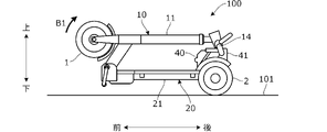
- FIG. 1 is a side view showing the overall configuration of a vehicle according to an embodiment of the invention
- FIG. 1 is a plan view showing the overall configuration of a vehicle according to an embodiment of the invention
- FIG. The top view which omits a part of FIG. 2 and shows it.
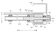
- Sectional drawing along the IV-IV line of FIG. Sectional drawing along the VV line of FIG. The figure which shows roughly the state which looked at the vehicle which concerns on embodiment of this invention from back.
- FIG. 7B is a diagram for explaining the operation of changing the attitude of the vehicle according to the embodiment of the present invention, and is a diagram showing the operation following FIG. 7A;
- FIG. 7A is a diagram showing the operation following FIG. 7A;
- FIG. 7C is a diagram for explaining the operation of changing the attitude of the vehicle according to the embodiment of the present invention, and is a diagram showing the operation following FIG. 7B;
- FIG. 7B is a diagram for explaining the operation of changing the posture of the vehicle according to the embodiment of the present invention, and is a diagram showing the operation following FIG. 7C;
- the figure which shows the modification of FIG. Sectional drawing along the IX-IX line of FIG. FIG. 2 is a plan view schematically showing the placement of the occupant's feet on the steps when getting into the vehicle according to the embodiment of the present invention;
- FIG. A vehicle according to an embodiment of the present invention is a three-wheeled vehicle having a single front wheel and a pair of left and right rear wheels, and is configured so that a user can ride it in a standing position.
- FIG. 1 and 2 are a side view and a plan view, respectively, showing the overall configuration of a vehicle 100 according to an embodiment of the present invention, showing the running posture of the vehicle 100 when the vehicle is in use, that is, the running posture.
- position which cannot run is called a non-running
- FIG. 1 also shows the state of use of the user PS (chain double-dashed line).
- the longitudinal direction (longitudinal direction), lateral direction (width direction), and vertical direction (height direction) of the vehicle 100 are defined as shown in the figure, and the configuration of each part will be described according to these definitions.
- FIG. 1 is a view of vehicle 100 viewed from the left
- FIG. 2 is a view of vehicle 100 viewed from above.
- vehicle 100 has front wheels 1 and rear wheels 2, and a frame FL that forms the frame of vehicle 100.
- the front wheel 1 has the same diameter as the rear wheel 2 . Note that the front wheel 1 may have a smaller diameter or a larger diameter than the rear wheel 2 .
- a frame FL has a front frame 10 and a rear frame 20 .
- the front frame 10 has a vertically extending vertical pipe 11 having a substantially rectangular cross section and an inclined frame 12 extending rearward from the rear surface of the lower end of the vertical pipe 11 .
- the vertical pipe 11 extends obliquely such that the upper end is located rearward from the lower end.
- the tilt frame 12 tilts forward with an upward slope (forward upward). More specifically, the slanted frame 12 extends so that the rear end is positioned below the upper end of the front wheel 1 and the front end is positioned above the upper end of the front wheel 1 . is joined to the rear surface of the vertical pipe 11 .
- a through hole having a substantially cylindrical cross section is formed vertically in the vertical pipe 11, and a handle shaft 13 having a substantially circular cross section is rotatably inserted into the through hole.
- a handle 14 is fixed to the upper end of the handle shaft 13 at its center in the left-right direction, and a front fork 15 is fixed to the lower end of the handle shaft 13 .
- the handle shaft 13 is supported so as to be able to move up and down (extend and contract) with respect to the vertical pipe 11 .
- a lock mechanism for fixing the height of the handle shaft 13 is provided at the upper end of the vertical pipe 11 .
- a rotating shaft 1 a of the front wheel 1 is rotatably supported by a pair of left and right front forks 15 .
- the front wheels 1 are steered by a turning operation (steering) of the steering wheel 14 .
- the handle 14 is a bar handle that extends substantially linearly in the left-right direction, and both left and right ends of the handle 14 are provided with grips 14a made of resin or rubber that are gripped by the user PS.
- a substantially arc-shaped front fender 16 is attached to the inside of the pair of left and right front forks 15 so as to cover the periphery of the front wheel 1 from above to behind the front wheel 1 .
- a travel motor 4 in-wheel motor
- a brake unit 5 inside the front wheel 1, a travel motor 4 (in-wheel motor) and a brake unit 5 are housed.
- the traveling motor 4 is arranged on the left side
- the brake unit 5 is arranged on the right side.
- Vehicle 100 is configured as an electric vehicle that travels by being driven by travel motor 4 .
- the brake unit 5 is configured, for example, as a drum brake unit that constitutes a drum brake.
- the rear wheels 2 are similarly provided with brake units. These brake units 5 are operated by operating a brake lever 14b provided in front of a grip 14a of the handle 14, and braking force is applied to the front wheels 1 and the rear wheels 2. As shown in FIG.
- the traveling motor 4 as an electric motor may be provided in the rear wheels 2 instead of the front wheels 1, or may be provided in both the front wheels 1 and the rear wheels 2. By providing the traveling motors for both the front wheels 1 and the rear wheels 2, the traction ability and hill-climbing ability of the vehicle 100 can be improved.
- the steering wheel 14 is provided with a starter switch for turning on/off the main power supply, a blinker switch for turning left or right, an accelerator lever for inputting a travel command, and the like, which can be operated by the user.
- the steering wheel 14 may be provided with a display section for displaying vehicle information such as remaining battery capacity and set vehicle speed.
- a pair of left and right winker lamps are provided that blink when a winker switch is operated.
- a headlight is provided at the upper end of the vertical pipe 11 .
- FIG. 3 is a plan view showing the overall configuration of vehicle 100 with step 30 and battery 40 omitted.
- the rear frame 20 includes a main frame 21 having a substantially rectangular or substantially circular cross section extending in the front-rear direction along the center line CL1, and a main frame 21 extending in the left-right direction across the main frame 21. and a pair of left and right support frames 24 extending in the left-right direction from the rear end of the main frame 21 . Note that these frames 21 to 24 are indicated by dotted lines in FIG.
- two recesses 21a are formed in the front and rear sides of the upper surface of the main frame 21 in the left-right direction, and the lateral frames 22 and 23 are fitted and joined to the recesses 21a.
- the lateral length of the lateral frame 23 is longer than the lateral length of the lateral frame 22 and shorter than the distance between the left and right rear wheels 2 .
- the upper surfaces of the lateral frames 22 and 23 are positioned on the same horizontal plane parallel to the road surface 101 ( FIG. 1 ) and above the upper surface of the main frame 21 .
- the top surfaces of the lateral frames 22 and 23 may be positioned on the same plane as the top surface of the main frame 21 .
- a pair of left and right support frames 24 protrude in the left and right direction from left and right side surfaces of the main frame 21 .
- a single support frame 24 can also be provided through the main frame 21 .
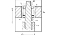
- FIG. 4 is a cross-sectional view showing the configuration of the mounting portion of the rear wheel 2, that is, a cross-sectional view taken along line IV-IV in FIG.
- a shaft 25 is attached to the tip of the support frame 24 .
- a wheel 2 a of the rear wheel 2 is rotatably supported on the shaft 25 via a pair of left and right bearings 26 .
- a substantially cylindrical collar 27 is interposed between the support frame 24 and the bearing 26 .
- a nut 28 is screwed onto the tip of the shaft 25 so as to constrain the position of the bearing 26 .
- the front frame 10 further has a base frame 17 behind the tilt frame 12 .
- the base frame 17 is a substantially rectangular plate-like member in plan view, and a step 30 is arranged behind the base frame 17 .
- the width (horizontal direction length) of the base frame 17 is substantially equal to the width of the lateral frame 22 .
- the front end of the base frame 17 is provided with a bracket 18 projecting upward and forward from the base frame 17 .
- a rear end portion of the tilt frame 12 is rotatably supported by a bracket 18 about an axis line CL2 extending in the left-right direction. Accordingly, the vehicle 100 can be folded, and the vehicle 100 can be easily transported in the folded state (see FIG. 7D).
- the bracket 18 is provided with a lock mechanism that prevents the tilt frame 12 from rotating about the axis CL2. Therefore, the vehicle 100 can be held in the traveling posture shown in FIG.
- step 30 The configuration of step 30 will be explained.
- steps (footrests) 30, which are generally rectangular plate members extending in the front-rear direction and the left-right direction, are mounted.
- the step 30 is fixed to the horizontal frames 22 and 23 by welding or the like, so that both ends of the step 30 in the front-rear direction are supported by the horizontal frames 22 and 23 .
- the step 30 may also be mounted on the upper surface of the main frame 21 and supported by the main frame 21 and the lateral frames 22 and 23 .
- the step 30 constitutes a placing portion on which the user PS in a standing posture places both feet, and the upper surface (placing surface) of the step 30 is configured as a horizontal plane parallel to the road surface 101 .
- the step 30 includes a rear step portion 31 extending from the rear end to the front with a constant width (horizontal direction length) and a front step portion extending from the front end to the rear with a constant width. and an intermediate step portion 33 between the rear step portion 31 and the front step portion 32 .
- a rear end 30a of the step 30 extends substantially linearly in the left-right direction.
- the step 30 has a length in the front-rear direction and a width in the left-right direction so that the entire sole of the user PS can be placed thereon.
- the width Wa of the rear step portion 31 is shorter than the length W1 between the laterally outer end faces of the left and right rear wheels 2 and longer than the laterally inner end face length W2.
- the width Wa may be substantially equal to the length W1 or W2.
- the width Wb of the front step portion 32 is substantially equal to the width of the base frame 17 and shorter than the width Wa of the rear step portion 31 .
- the intermediate step portion 33 is formed in a substantially trapezoidal shape in plan view so as to smoothly connect the front step portion 32 and the rear step portion 31 . As a result, the width of the step 30 gradually expands from the front to the rear.
- the step 30 By constructing the step 30 with a single plate member in this way, the number of parts can be reduced and the cost can be reduced compared to the case where the step is divided into left and right parts. Moreover, the area of the upper surface of the step 30 can be increased, and the degree of freedom of the place where the user's PS puts his or her feet is improved. As shown in FIG. 1, the top surface of the step 30 is positioned on the same horizontal plane as the top surface of the base frame 17 . Therefore, the user PS can easily move the sole of the foot from the upper surface of the step 30 to the upper surface of the base frame 17, thereby expanding the range in which the sole can be placed.
- a pair of left and right rear fenders 34 are attached to the rear end of the step 30 .
- the rear fender 34 is formed in a substantially arc shape so as to cover the periphery of the rear wheel 2 from the front to the top and rear of the rear wheel 2 .
- the length from the right end surface of the right rear fender 34 to the left end surface of the left rear fender 34 is shorter than the length from the right end to the left end of the handle 14, and the maximum width of the vehicle 100 is defined by the handle 14. .
- a holder 41 for the battery 40 is arranged behind the step 30 .
- the holder 41 is configured in a substantially box shape with an open front surface. More specifically, the holder 41 has a bottom wall and a top wall facing each other and extending substantially horizontally, and a pair of left and right side walls and a rear wall standing between the side walls and the top wall. , the bottom wall is mounted and supported on the upper surface of the rear end of the main frame 21 and the upper surface of the support frame 24 .
- a substantially box-shaped battery 40 is inserted into the holder 41 through an opening on the front surface, thereby supporting the battery 40 .
- the top surface of the bottom wall is formed substantially flush with the top surface of the step 30 .
- the battery 40 can be easily accommodated in or removed from the holder 41 while sliding the battery 40 in the front-rear direction along the upper surface of the step 30 .
- a terminal portion is provided on the rear wall of the holder 41, and the terminal portion of the battery 40 is connected to this terminal portion when the battery 40 is accommodated.
- the battery 40 is a secondary battery such as a lithium ion battery that stores electric power supplied to the traveling motor 4 . 1 traveling motor 4 is connected. Electric power supplied from the battery 40 to the travel motor 4 is controlled by a power control unit (not shown). Note that the battery 40 may be arranged behind or inside the vertical pipe 11, or may be arranged around other structural members.
- the front frame 10 and the rear frame 20 are connected via the swinging portion 50 . That is, the base frame 17 provided at the rear end portion of the front frame 10 and the main frame 21 provided at the front end portion of the rear frame 20 are connected via the swing portion 50 so as to be capable of swinging in the horizontal direction.
- the front side of the swinging portion 50 of the vehicle 100 may be referred to as the first component portion 100A
- the rear side thereof may be referred to as the second component portion 100B.
- the first component 100A includes the front wheel 1, the handle 14, and the like.
- the second component 100B includes a rear wheel 2, a step 30, and the like.
- the first component portion 100A is provided so as to be able to swing in the left-right direction with respect to the second component portion 100B about a swing axis CL3 extending in the front-rear direction.
- the rocking part 50 has a Neidhardt rubber spring 51 fixed to the bottom surface of the base frame 17 .
- FIG. 5 is a diagram showing a schematic configuration of the Neidhardt rubber spring 51 provided in the swinging portion 50.
- the Neidhardt rubber spring 51 is housed in a case 511 having a substantially rectangular frame shape in cross section and fixed to the bottom surface of the base frame 17 .
- a shaft 512 having a substantially cylindrical cross section is arranged integrally with the main frame 21 of the rear frame 20 and extending along the axis CL3.
- the front end portion of the main frame 21 may be configured to have a substantially circular cross section and used as the shaft 512 .
- the Neidhardt rubber spring 51 includes a substantially diamond-shaped cam block 513 spline-connected to the shaft 512 so as to be rotatable integrally with the shaft 512 , and rubber rollers arranged to face concave surfaces of the cam block 513 . 514.
- FIG. 5 corresponds to the initial state before the swinging portion 50 swings.
- FIG. 6 is a view of the vehicle 100 viewed from the rear, corresponding to the initial state before rocking. Note that FIG. 6 simply shows the configuration of the vehicle 100 . As shown in FIG. 6, the vertical pipe 11 extends substantially perpendicularly to the road surface 101 in the initial state. The posture of the vehicle 100 in this case is called a reference posture.
- the user PS who gets into the vehicle 100 in a standing posture can easily turn the vehicle 100 in the left-right direction.
- the vehicle 100 turns left and right
- the user slightly bends the knees and ankles and tilts the upper body left and right.
- the vertical pipe 11 is swung together with the base frame 17 in a stable posture with both feet placed on the step 30 while the step 30 integrated with the rear frame 20 is kept horizontal, and the front wheel 1 is tilted left and right. be able to.
- the vehicle 100 can be smoothly turned, and the turning performance is improved.
- the Neidhardt rubber spring 51 is provided in the swinging portion 50, when the front frame 10 (base frame 17) is swung left and right from the reference posture, a restoring force acts on the front frame 10, and the front frame 10 can be well suppressed.
- the cam block 513 may be formed in a polygonal shape (for example, a triangular shape) instead of a square shape.
- a restoring force may be applied to the front frame 10 by an elastic member such as a coil spring instead of the Neidhardt rubber spring 51 . That is, the configuration of the damper member is not limited to the Neidhardt rubber spring 51 .
- the weight of the user in a standing posture acts on the step 30 (the center point of the load acting from the soles of the feet) is the ground contact point of the front wheel 1 and the pair of left and right rear wheels 2 in plan view. Located within the triangular area connecting the respective ground points. As a result, the user can get into the vehicle 100 in a stable posture during both running and stopping.
- the swing part 50 is arranged below the step 30, and the swing axis CL3 extends below the step 30 in the front-rear direction. Therefore, the step 30 can be easily formed in a large size even though the oscillating portion 50 is provided. Further, since the rocking portion 50 is hidden from the field of view of the user PS standing on the step 30, the appearance of the vehicle 100 is good.
- the vehicle 100 according to the present embodiment is provided so as to be foldable around the axis CL2 of the bracket 18 of the front frame 10 as described above.
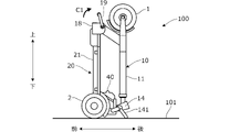
- 7A to 7D are diagrams showing examples of attitude changes from the running attitude of the vehicle 100.
- FIG. 7A to 7C correspond to the directions shown in FIGS. 1 and 2, respectively.
- the folded posture is included in the non-running posture of vehicle 100 .
- FIG. 7C the main frame 21 is raised and the vehicle 100 can be raised.
- the pair of left and right rear wheels 2 and the pair of left and right protrusions 141 provided on the handle 14 come into contact with the road surface 101 .
- a handle 19 is provided on the bracket 18 so as to be rotatable coaxially with the axis CL2.
- FIG. 7C the vehicle 100 is tilted forward with the rear wheels 2 as fulcrums. Accordingly, the vehicle 100 can be easily transported while rolling the rear wheels 2 on the road surface 101 .
- a vehicle 100 includes a first component 100A having a single front wheel 1 and a handlebar 14 disposed above the front wheel 1, a pair of left and right rear wheels 2, and an occupant.
- a second component 100B having a step 30 (placement portion) on which a foot is placed, and a first component 100A and a second component 100B centered on a swing axis CL3 extending in the front-rear direction. and a swinging portion 50 (connecting portion) that connects the and so as to be swingable in the left-right direction (FIG. 1).
- the step 30 is configured by a single plate member extending substantially horizontally and having a rear end 30a extending in the left-right direction (FIG. 2).
- the second component 100B has a support frame 24 that rotatably supports the pair of left and right rear wheels 2 (Fig. 3).
- the rear end of the step 30 is supported by a horizontal frame 23 integrally connected to a support frame 24 via a main frame 21 (Fig. 2).
- the step 30 can be firmly supported in the vicinity of the rear wheel 2 . That is, since the step 30 is provided so as not to swing with respect to the rear wheel 2, the step 30 can be integrally supported with the rear wheel support member.
- the second component 100B has a main frame 21 extending substantially in the front-rear direction, and a support frame 24 extending in the left-right direction across the rear end of the main frame 21 (FIG. 3). Therefore, the configuration of the support frame 24 that rotatably supports the left and right rear wheels 2 can be simplified, and the number of parts and costs can be reduced. In addition, the rigidity of the support frame 24 is increased, and the rear wheel 2 can be firmly supported.
- the first component 100A has a base frame 17 which is arranged in front of the step 30 and whose upper surface extends substantially horizontally (FIGS. 1 and 2).
- the upper surface of the step 30 and the upper surface of the base frame 17 extend substantially on the same plane (FIG. 1). This allows the user PS to easily move the sole from the step 30 to the upper surface of the base frame 17, increasing the space for placing the sole.
- the axis CL3 of the swinging portion 50 is positioned below the step 30 (FIG. 1). Thereby, the size of the step 30 can be easily increased without interfering with the oscillating portion 50 . Further, since the rocking portion 50 is hidden from the field of view of the user PS standing on the step 30, the appearance of the vehicle 100 is good.
- the rocking part 50 is arranged in front of the step 30 .
- the first component portion 100A and the second component portion 100B are separated in front of the step 30, and the first component portion 100A (the front wheel 1, etc.) of the vehicle 100 is satisfactorily swung in the left-right direction in front of the step 30. be able to.
- the step 30 is arranged in front of the left and right rear wheels 2 . Therefore, compared with the case where steps are provided inside the left and right rear wheels 2, an increase in vehicle width can be suppressed. As a result, the width of the vehicle can be reduced, and the vehicle can easily travel in a narrow passage.
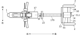
- FIG. 8 is a plan view of vehicle 100 showing an example thereof
- FIG. 9 is a cross-sectional view taken along line IX-IX in FIG. 8, like FIG. 3, step 30 and battery 40 are omitted from illustration.
- the swinging portion 50 is arranged not under the base frame 17 but between the left and right rear wheels 2 , more specifically behind the front end of the rear wheels 2 .
- a front end portion of the main frame 170 extending in the front-rear direction along the center line CL1 is fixed to the base frame 17 . Therefore, the main frame 170 constitutes the front frame 10 integral with the base frame 17 .
- the shaft 512 of the swinging portion 50 is joined to the rear end portion of the main frame 170, and the shaft 512 and the main frame 170 rotate integrally around the axis CL3.
- the oscillating portion 50 is surrounded by a substantially box-shaped case frame 55 , and the case 511 ( FIG. 5 ) of the oscillating portion 50 is housed inside the case frame 55 .
- Case 511 is provided integrally with case frame 55 .
- the shaft 512 passes through the case frame 55 in the front-rear direction and is rotatably supported by the case frame 55 by a pair of front and rear bearings 56 .
- a nut 57 is screwed onto the rear end of the shaft 512 .
- a cover 58 is attached to the rear end surface of the case frame 55 so as to cover the nut 57 .
- the support frame 24 protrudes in the left-right direction from the left and right side surfaces of the case frame 55 and is provided integrally with the case frame 55 .
- the case frame 55 is formed in a stepped shape so that the front side is tapered, and the horizontal frame 23 is mounted and joined to the upper surface of the tapered portion 552 on the front side of the stepped portion 551 .
- the front lateral frame 22 is rotatably supported on the outer peripheral surface of the main frame 170 via a sliding bearing 171 .
- the pair of front and rear lateral frames 22 and 23 are rotatable with respect to the main frame 170 , and the main frame 170 is rotatable relative to the step 30 .
- the swinging portion 50 By providing the swinging portion 50 behind the front end portion of the rear wheel 2 in this way, the swinging portion 50 can be arranged at a higher place than when it is arranged below the base frame 17 (FIG. 1). can be done.
- the vehicle 100 climbs over a step or the like, it is possible to prevent the swinging portion 50 from colliding with the step.
- the rear end of the step 30 abuts on the stepped portion 551 .
- a holder 41 is fixed to the case frame 55 .
- the case frame 55 is formed so that its top surface is flush with the top surface of the step 30 . Therefore, the battery 40 can be easily accommodated in the holder 41 through the opening 41a on the front side of the holder 41 while the upper surface of the step 30 is slid.
- the members on the front side of the swinging portion 50 that is, the front wheel 1 and the front frame 10 (the vertical pipe 11, the handlebar 14, the base frame 17, etc.) are configured as the first component portion 100A.
- the configuration of the first component is not limited to the one described above as long as it has one front wheel and a steering unit disposed above the front wheel.
- the members on the rear side of the swinging portion 50 that is, the rear wheel 2 and the rear frame 20 (main frame 21, support frame 24, step 30, etc.) are connected to the second component portion 100B.
- the configuration of the second component is not limited to that described above as long as it has a pair of left and right rear wheels and a placing portion on which the feet of the passenger are placed.
- the first component portion 100A and the second component portion 100B are connected via the swing portion 50 so as to be able to swing in the left-right direction.
- Any configuration of the connecting portion may be used as long as it is connected so as to be able to swing.
- the step 30 is formed to have the front step portion 32, the rear step portion 31, and the intermediate step portion 33.
- the step as a mounting portion may have any configuration.
- step 30 is configured as in the above embodiment, the following effects can also be obtained.
- FIG. 10 is a plan view schematically showing the placement of the occupant's feet on the step 30 when riding. 10 also shows the contact point P1 of the front wheel 1 and the contact point P2 of the pair of left and right rear wheels 2. As shown in FIG.
- the balls of the feet RF1, LF1 and the heel bones RF2, LF2 of both the left and right feet of the occupant are placed on the step 30 when riding.
- the passenger can take a stable standing posture on the step 30 without increasing the size of the step 30. - ⁇ Since there is no need to increase the size of the step 30, costs can be suppressed.
- the step 30 includes a rear step portion 31 (first placement portion) having a predetermined width Wa (first predetermined width) in the horizontal direction and a predetermined width Wb (second predetermined width) shorter than Wa. ) (see FIG. 2). Therefore, as shown in FIG. 10, in the general riding posture of the occupant, the length of the line segments LN1, LN2 connecting the centers of the occupant's thenars RF1, LF1 and the calcaneus RF2, LF2 is more than half. is included in an area AR1 that connects the contact point P1 of the front wheel 1 and the contact points P2 of the left and right rear wheels 2 in plan view. As a result, the center of gravity of the occupant is always positioned within the area AR1, thereby stabilizing the vehicle attitude.
- the rear end of the step extends in the left-right direction.
- the rear wheel 2 is made rotatable by the support frame 24 (second frame) extending in the left-right direction across the rear end of the main frame 21 (first frame) extending in the front-rear direction.
- the configuration of the support portion is not limited to that described above.
- the rear end of the step 30 is supported by the connection portion connected to the support frame 24, that is, the main frame 21 or the lateral frame 23, but the support frame 24 may also be used.
- the base frame 17, which is part of the first component part 100A, is arranged in front of the step 30, but the configuration of the horizontal part is not limited to that described above.
- the top surface of the step 30 and the top surface of the base frame 17 may not be on the same plane.
- the axis CL3 of the swinging portion 50 is positioned below the step 30, but the arrangement of the swinging axis is not limited to that described above.
Landscapes
- Engineering & Computer Science (AREA)
- Mechanical Engineering (AREA)
- Automatic Cycles, And Cycles In General (AREA)
Priority Applications (3)
| Application Number | Priority Date | Filing Date | Title |
|---|---|---|---|
| CN202280020005.3A CN116981615A (zh) | 2021-03-12 | 2022-03-07 | 车辆 |
| JP2023505536A JP7830422B2 (ja) | 2021-03-12 | 2022-03-07 | 車両 |
| EP22767071.8A EP4306187A4 (en) | 2021-03-12 | 2022-03-07 | Vehicle |
Applications Claiming Priority (2)
| Application Number | Priority Date | Filing Date | Title |
|---|---|---|---|
| JP2021040727 | 2021-03-12 | ||
| JP2021-040727 | 2021-03-12 |
Publications (1)
| Publication Number | Publication Date |
|---|---|
| WO2022191115A1 true WO2022191115A1 (ja) | 2022-09-15 |
Family
ID=83226636
Family Applications (1)
| Application Number | Title | Priority Date | Filing Date |
|---|---|---|---|
| PCT/JP2022/009657 Ceased WO2022191115A1 (ja) | 2021-03-12 | 2022-03-07 | 車両 |
Country Status (4)
| Country | Link |
|---|---|
| EP (1) | EP4306187A4 (https=) |
| JP (1) | JP7830422B2 (https=) |
| CN (1) | CN116981615A (https=) |
| WO (1) | WO2022191115A1 (https=) |
Cited By (1)
| Publication number | Priority date | Publication date | Assignee | Title |
|---|---|---|---|---|
| US20230391416A1 (en) * | 2020-10-27 | 2023-12-07 | Striemo Inc. | Vehicle |
Citations (4)
| Publication number | Priority date | Publication date | Assignee | Title |
|---|---|---|---|---|
| JPS55144190U (https=) * | 1979-04-05 | 1980-10-16 | ||
| JPH08310254A (ja) | 1995-05-17 | 1996-11-26 | Honda Motor Co Ltd | 電動車のバッテリ取付け構造 |
| JP2004243949A (ja) * | 2003-02-14 | 2004-09-02 | Honda Motor Co Ltd | 揺動式自動3輪車 |
| CN1597431A (zh) * | 2004-09-27 | 2005-03-23 | 常州体极车业有限公司 | 三轮滑板车 |
Family Cites Families (10)
| Publication number | Priority date | Publication date | Assignee | Title |
|---|---|---|---|---|
| US3605929A (en) * | 1969-07-07 | 1971-09-20 | Burton A Rolland | One rider golf cart |
| JPS5931590U (ja) * | 1982-08-24 | 1984-02-27 | スズキ株式会社 | 3輪車の車体構造 |
| AU6898998A (en) * | 1997-04-15 | 1998-11-11 | Empower Corporation | Portable scooter |
| KR20080103153A (ko) * | 2007-05-23 | 2008-11-27 | 박훈근 | 전동식 및 핸들 조작에 의해 구동되는 자전거 |
| KR101158493B1 (ko) * | 2009-04-10 | 2012-06-21 | 오상우 | 킥보드 |
| WO2013162082A1 (ko) * | 2012-04-23 | 2013-10-31 | Lee Kook Hwan | 자세제어 기능을 갖는 차량 |
| GB2560740A (en) * | 2017-03-23 | 2018-09-26 | Richard Manning John | Tricycle |
| WO2020160406A1 (en) * | 2019-01-31 | 2020-08-06 | Rollo Motion, Inc. | Autonomous urban transport vehicle |
| WO2020204869A1 (ru) * | 2019-04-01 | 2020-10-08 | Иван Иванович КОТУРБАЧ | Адаптивный трехколесный электросамокат |
| JP7544161B2 (ja) * | 2023-01-30 | 2024-09-03 | いすゞ自動車株式会社 | バッテリ管理装置 |
-
2022
- 2022-03-07 EP EP22767071.8A patent/EP4306187A4/en active Pending
- 2022-03-07 JP JP2023505536A patent/JP7830422B2/ja active Active
- 2022-03-07 CN CN202280020005.3A patent/CN116981615A/zh active Pending
- 2022-03-07 WO PCT/JP2022/009657 patent/WO2022191115A1/ja not_active Ceased
Patent Citations (4)
| Publication number | Priority date | Publication date | Assignee | Title |
|---|---|---|---|---|
| JPS55144190U (https=) * | 1979-04-05 | 1980-10-16 | ||
| JPH08310254A (ja) | 1995-05-17 | 1996-11-26 | Honda Motor Co Ltd | 電動車のバッテリ取付け構造 |
| JP2004243949A (ja) * | 2003-02-14 | 2004-09-02 | Honda Motor Co Ltd | 揺動式自動3輪車 |
| CN1597431A (zh) * | 2004-09-27 | 2005-03-23 | 常州体极车业有限公司 | 三轮滑板车 |
Non-Patent Citations (1)
| Title |
|---|
| See also references of EP4306187A4 |
Cited By (2)
| Publication number | Priority date | Publication date | Assignee | Title |
|---|---|---|---|---|
| US20230391416A1 (en) * | 2020-10-27 | 2023-12-07 | Striemo Inc. | Vehicle |
| US12037070B2 (en) * | 2020-10-27 | 2024-07-16 | Striemo Inc. | Foldable vehicle |
Also Published As
| Publication number | Publication date |
|---|---|
| CN116981615A (zh) | 2023-10-31 |
| JP7830422B2 (ja) | 2026-03-16 |
| EP4306187A1 (en) | 2024-01-17 |
| EP4306187A4 (en) | 2024-11-27 |
| JPWO2022191115A1 (https=) | 2022-09-15 |
Similar Documents
| Publication | Publication Date | Title |
|---|---|---|
| JP6935610B1 (ja) | 車両 | |
| JP4710934B2 (ja) | 車体構造及び同軸二輪車 | |
| US11851130B2 (en) | Vehicle | |
| WO2022191115A1 (ja) | 車両 | |
| JP7420699B2 (ja) | 車両 | |
| JP2006151032A (ja) | 立ち乗り式小型車両 | |
| CN116390881B (zh) | 车辆 | |
| JP7515003B2 (ja) | 車両 | |
| JP2022140080A (ja) | 車両 | |
| JP7420693B2 (ja) | 車両 | |
| JP7399056B2 (ja) | 車両 | |
| JP5688802B2 (ja) | ライディングシミュレータ | |
| JP7549023B2 (ja) | 車両 | |
| WO2023073855A1 (ja) | 車両 | |
| JP7623002B2 (ja) | 電動スクータ | |
| JP7399993B2 (ja) | 自転車用両脚スタンドおよび自転車 | |
| JP2026003176A (ja) | 立ち乗りモビリティ | |
| JP2025141127A (ja) | 電動スケーター |
Legal Events
| Date | Code | Title | Description |
|---|---|---|---|
| 121 | Ep: the epo has been informed by wipo that ep was designated in this application |
Ref document number: 22767071 Country of ref document: EP Kind code of ref document: A1 |
|
| WWE | Wipo information: entry into national phase |
Ref document number: 2023505536 Country of ref document: JP |
|
| WWE | Wipo information: entry into national phase |
Ref document number: 202280020005.3 Country of ref document: CN |
|
| WWE | Wipo information: entry into national phase |
Ref document number: 2022767071 Country of ref document: EP |
|
| NENP | Non-entry into the national phase |
Ref country code: DE |
|
| ENP | Entry into the national phase |
Ref document number: 2022767071 Country of ref document: EP Effective date: 20231012 |