WO2022191109A1 - 接合シートおよびその製造方法 - Google Patents
接合シートおよびその製造方法 Download PDFInfo
- Publication number
- WO2022191109A1 WO2022191109A1 PCT/JP2022/009645 JP2022009645W WO2022191109A1 WO 2022191109 A1 WO2022191109 A1 WO 2022191109A1 JP 2022009645 W JP2022009645 W JP 2022009645W WO 2022191109 A1 WO2022191109 A1 WO 2022191109A1
- Authority
- WO
- WIPO (PCT)
- Prior art keywords
- solder particles
- mass
- sheet
- less
- solder
- Prior art date
- Legal status (The legal status is an assumption and is not a legal conclusion. Google has not performed a legal analysis and makes no representation as to the accuracy of the status listed.)
- Ceased
Links
Images





Classifications
-
- B—PERFORMING OPERATIONS; TRANSPORTING
- B23—MACHINE TOOLS; METAL-WORKING NOT OTHERWISE PROVIDED FOR
- B23K—SOLDERING OR UNSOLDERING; WELDING; CLADDING OR PLATING BY SOLDERING OR WELDING; CUTTING BY APPLYING HEAT LOCALLY, e.g. FLAME CUTTING; WORKING BY LASER BEAM
- B23K35/00—Rods, electrodes, materials, or media, for use in soldering, welding, or cutting
- B23K35/02—Rods, electrodes, materials, or media, for use in soldering, welding, or cutting characterised by mechanical features, e.g. shape
- B23K35/0222—Rods, electrodes, materials, or media, for use in soldering, welding, or cutting characterised by mechanical features, e.g. shape for use in soldering or brazing
- B23K35/0233—Sheets or foils
-
- B—PERFORMING OPERATIONS; TRANSPORTING
- B23—MACHINE TOOLS; METAL-WORKING NOT OTHERWISE PROVIDED FOR
- B23K—SOLDERING OR UNSOLDERING; WELDING; CLADDING OR PLATING BY SOLDERING OR WELDING; CUTTING BY APPLYING HEAT LOCALLY, e.g. FLAME CUTTING; WORKING BY LASER BEAM
- B23K1/00—Soldering, e.g. brazing, or unsoldering
-
- B—PERFORMING OPERATIONS; TRANSPORTING
- B23—MACHINE TOOLS; METAL-WORKING NOT OTHERWISE PROVIDED FOR
- B23K—SOLDERING OR UNSOLDERING; WELDING; CLADDING OR PLATING BY SOLDERING OR WELDING; CUTTING BY APPLYING HEAT LOCALLY, e.g. FLAME CUTTING; WORKING BY LASER BEAM
- B23K35/00—Rods, electrodes, materials, or media, for use in soldering, welding, or cutting
- B23K35/02—Rods, electrodes, materials, or media, for use in soldering, welding, or cutting characterised by mechanical features, e.g. shape
- B23K35/0205—Non-consumable electrodes; C-electrodes
-
- B—PERFORMING OPERATIONS; TRANSPORTING
- B23—MACHINE TOOLS; METAL-WORKING NOT OTHERWISE PROVIDED FOR
- B23K—SOLDERING OR UNSOLDERING; WELDING; CLADDING OR PLATING BY SOLDERING OR WELDING; CUTTING BY APPLYING HEAT LOCALLY, e.g. FLAME CUTTING; WORKING BY LASER BEAM
- B23K35/00—Rods, electrodes, materials, or media, for use in soldering, welding, or cutting
- B23K35/22—Rods, electrodes, materials, or media, for use in soldering, welding, or cutting characterised by the composition or nature of the material
- B23K35/24—Selection of soldering or welding materials proper
- B23K35/26—Selection of soldering or welding materials proper with the principal constituent melting at less than 400°C
-
- B—PERFORMING OPERATIONS; TRANSPORTING
- B23—MACHINE TOOLS; METAL-WORKING NOT OTHERWISE PROVIDED FOR
- B23K—SOLDERING OR UNSOLDERING; WELDING; CLADDING OR PLATING BY SOLDERING OR WELDING; CUTTING BY APPLYING HEAT LOCALLY, e.g. FLAME CUTTING; WORKING BY LASER BEAM
- B23K35/00—Rods, electrodes, materials, or media, for use in soldering, welding, or cutting
- B23K35/22—Rods, electrodes, materials, or media, for use in soldering, welding, or cutting characterised by the composition or nature of the material
- B23K35/24—Selection of soldering or welding materials proper
- B23K35/26—Selection of soldering or welding materials proper with the principal constituent melting at less than 400°C
- B23K35/264—Bi as the principal constituent
-
- B—PERFORMING OPERATIONS; TRANSPORTING
- B23—MACHINE TOOLS; METAL-WORKING NOT OTHERWISE PROVIDED FOR
- B23K—SOLDERING OR UNSOLDERING; WELDING; CLADDING OR PLATING BY SOLDERING OR WELDING; CUTTING BY APPLYING HEAT LOCALLY, e.g. FLAME CUTTING; WORKING BY LASER BEAM
- B23K35/00—Rods, electrodes, materials, or media, for use in soldering, welding, or cutting
- B23K35/22—Rods, electrodes, materials, or media, for use in soldering, welding, or cutting characterised by the composition or nature of the material
- B23K35/36—Selection of non-metallic compositions, e.g. coatings or fluxes; Selection of soldering or welding materials, conjoint with selection of non-metallic compositions, both selections being of interest
- B23K35/3601—Selection of non-metallic compositions, e.g. coatings or fluxes; Selection of soldering or welding materials, conjoint with selection of non-metallic compositions, both selections being of interest with inorganic compounds as principal constituents
-
- B—PERFORMING OPERATIONS; TRANSPORTING
- B23—MACHINE TOOLS; METAL-WORKING NOT OTHERWISE PROVIDED FOR
- B23K—SOLDERING OR UNSOLDERING; WELDING; CLADDING OR PLATING BY SOLDERING OR WELDING; CUTTING BY APPLYING HEAT LOCALLY, e.g. FLAME CUTTING; WORKING BY LASER BEAM
- B23K35/00—Rods, electrodes, materials, or media, for use in soldering, welding, or cutting
- B23K35/22—Rods, electrodes, materials, or media, for use in soldering, welding, or cutting characterised by the composition or nature of the material
- B23K35/36—Selection of non-metallic compositions, e.g. coatings or fluxes; Selection of soldering or welding materials, conjoint with selection of non-metallic compositions, both selections being of interest
- B23K35/3612—Selection of non-metallic compositions, e.g. coatings or fluxes; Selection of soldering or welding materials, conjoint with selection of non-metallic compositions, both selections being of interest with organic compounds as principal constituents
- B23K35/3613—Polymers, e.g. resins
-
- B—PERFORMING OPERATIONS; TRANSPORTING
- B23—MACHINE TOOLS; METAL-WORKING NOT OTHERWISE PROVIDED FOR
- B23K—SOLDERING OR UNSOLDERING; WELDING; CLADDING OR PLATING BY SOLDERING OR WELDING; CUTTING BY APPLYING HEAT LOCALLY, e.g. FLAME CUTTING; WORKING BY LASER BEAM
- B23K35/00—Rods, electrodes, materials, or media, for use in soldering, welding, or cutting
- B23K35/22—Rods, electrodes, materials, or media, for use in soldering, welding, or cutting characterised by the composition or nature of the material
- B23K35/36—Selection of non-metallic compositions, e.g. coatings or fluxes; Selection of soldering or welding materials, conjoint with selection of non-metallic compositions, both selections being of interest
- B23K35/362—Selection of compositions of fluxes
-
- B—PERFORMING OPERATIONS; TRANSPORTING
- B23—MACHINE TOOLS; METAL-WORKING NOT OTHERWISE PROVIDED FOR
- B23K—SOLDERING OR UNSOLDERING; WELDING; CLADDING OR PLATING BY SOLDERING OR WELDING; CUTTING BY APPLYING HEAT LOCALLY, e.g. FLAME CUTTING; WORKING BY LASER BEAM
- B23K35/00—Rods, electrodes, materials, or media, for use in soldering, welding, or cutting
- B23K35/22—Rods, electrodes, materials, or media, for use in soldering, welding, or cutting characterised by the composition or nature of the material
- B23K35/36—Selection of non-metallic compositions, e.g. coatings or fluxes; Selection of soldering or welding materials, conjoint with selection of non-metallic compositions, both selections being of interest
- B23K35/365—Selection of non-metallic compositions of coating materials either alone or conjoint with selection of soldering or welding materials
-
- B—PERFORMING OPERATIONS; TRANSPORTING
- B23—MACHINE TOOLS; METAL-WORKING NOT OTHERWISE PROVIDED FOR
- B23K—SOLDERING OR UNSOLDERING; WELDING; CLADDING OR PLATING BY SOLDERING OR WELDING; CUTTING BY APPLYING HEAT LOCALLY, e.g. FLAME CUTTING; WORKING BY LASER BEAM
- B23K35/00—Rods, electrodes, materials, or media, for use in soldering, welding, or cutting
- B23K35/40—Making wire or rods for soldering or welding
-
- C—CHEMISTRY; METALLURGY
- C08—ORGANIC MACROMOLECULAR COMPOUNDS; THEIR PREPARATION OR CHEMICAL WORKING-UP; COMPOSITIONS BASED THEREON
- C08K—Use of inorganic or non-macromolecular organic substances as compounding ingredients
- C08K3/00—Use of inorganic substances as compounding ingredients
- C08K3/02—Elements
- C08K3/08—Metals
-
- C—CHEMISTRY; METALLURGY
- C08—ORGANIC MACROMOLECULAR COMPOUNDS; THEIR PREPARATION OR CHEMICAL WORKING-UP; COMPOSITIONS BASED THEREON
- C08K—Use of inorganic or non-macromolecular organic substances as compounding ingredients
- C08K5/00—Use of organic ingredients
- C08K5/04—Oxygen-containing compounds
- C08K5/09—Carboxylic acids; Metal salts thereof; Anhydrides thereof
-
- C—CHEMISTRY; METALLURGY
- C08—ORGANIC MACROMOLECULAR COMPOUNDS; THEIR PREPARATION OR CHEMICAL WORKING-UP; COMPOSITIONS BASED THEREON
- C08L—COMPOSITIONS OF MACROMOLECULAR COMPOUNDS
- C08L101/00—Compositions of unspecified macromolecular compounds
-
- C—CHEMISTRY; METALLURGY
- C09—DYES; PAINTS; POLISHES; NATURAL RESINS; ADHESIVES; COMPOSITIONS NOT OTHERWISE PROVIDED FOR; APPLICATIONS OF MATERIALS NOT OTHERWISE PROVIDED FOR
- C09J—ADHESIVES; NON-MECHANICAL ASPECTS OF ADHESIVE PROCESSES IN GENERAL; ADHESIVE PROCESSES NOT PROVIDED FOR ELSEWHERE; USE OF MATERIALS AS ADHESIVES
- C09J11/00—Features of adhesives not provided for in group C09J9/00, e.g. additives
- C09J11/02—Non-macromolecular additives
- C09J11/04—Non-macromolecular additives inorganic
-
- C—CHEMISTRY; METALLURGY
- C09—DYES; PAINTS; POLISHES; NATURAL RESINS; ADHESIVES; COMPOSITIONS NOT OTHERWISE PROVIDED FOR; APPLICATIONS OF MATERIALS NOT OTHERWISE PROVIDED FOR
- C09J—ADHESIVES; NON-MECHANICAL ASPECTS OF ADHESIVE PROCESSES IN GENERAL; ADHESIVE PROCESSES NOT PROVIDED FOR ELSEWHERE; USE OF MATERIALS AS ADHESIVES
- C09J11/00—Features of adhesives not provided for in group C09J9/00, e.g. additives
- C09J11/02—Non-macromolecular additives
- C09J11/06—Non-macromolecular additives organic
-
- C—CHEMISTRY; METALLURGY
- C09—DYES; PAINTS; POLISHES; NATURAL RESINS; ADHESIVES; COMPOSITIONS NOT OTHERWISE PROVIDED FOR; APPLICATIONS OF MATERIALS NOT OTHERWISE PROVIDED FOR
- C09J—ADHESIVES; NON-MECHANICAL ASPECTS OF ADHESIVE PROCESSES IN GENERAL; ADHESIVE PROCESSES NOT PROVIDED FOR ELSEWHERE; USE OF MATERIALS AS ADHESIVES
- C09J163/00—Adhesives based on epoxy resins; Adhesives based on derivatives of epoxy resins
-
- C—CHEMISTRY; METALLURGY
- C09—DYES; PAINTS; POLISHES; NATURAL RESINS; ADHESIVES; COMPOSITIONS NOT OTHERWISE PROVIDED FOR; APPLICATIONS OF MATERIALS NOT OTHERWISE PROVIDED FOR
- C09J—ADHESIVES; NON-MECHANICAL ASPECTS OF ADHESIVE PROCESSES IN GENERAL; ADHESIVE PROCESSES NOT PROVIDED FOR ELSEWHERE; USE OF MATERIALS AS ADHESIVES
- C09J201/00—Adhesives based on unspecified macromolecular compounds
-
- C—CHEMISTRY; METALLURGY
- C09—DYES; PAINTS; POLISHES; NATURAL RESINS; ADHESIVES; COMPOSITIONS NOT OTHERWISE PROVIDED FOR; APPLICATIONS OF MATERIALS NOT OTHERWISE PROVIDED FOR
- C09J—ADHESIVES; NON-MECHANICAL ASPECTS OF ADHESIVE PROCESSES IN GENERAL; ADHESIVE PROCESSES NOT PROVIDED FOR ELSEWHERE; USE OF MATERIALS AS ADHESIVES
- C09J7/00—Adhesives in the form of films or foils
- C09J7/30—Adhesives in the form of films or foils characterised by the adhesive composition
- C09J7/35—Heat-activated
-
- C—CHEMISTRY; METALLURGY
- C09—DYES; PAINTS; POLISHES; NATURAL RESINS; ADHESIVES; COMPOSITIONS NOT OTHERWISE PROVIDED FOR; APPLICATIONS OF MATERIALS NOT OTHERWISE PROVIDED FOR
- C09J—ADHESIVES; NON-MECHANICAL ASPECTS OF ADHESIVE PROCESSES IN GENERAL; ADHESIVE PROCESSES NOT PROVIDED FOR ELSEWHERE; USE OF MATERIALS AS ADHESIVES
- C09J9/00—Adhesives characterised by their physical nature or the effects produced, e.g. glue sticks
- C09J9/02—Electrically-conducting adhesives
-
- C—CHEMISTRY; METALLURGY
- C22—METALLURGY; FERROUS OR NON-FERROUS ALLOYS; TREATMENT OF ALLOYS OR NON-FERROUS METALS
- C22C—ALLOYS
- C22C12/00—Alloys based on antimony or bismuth
-
- H—ELECTRICITY
- H01—ELECTRIC ELEMENTS
- H01R—ELECTRICALLY-CONDUCTIVE CONNECTIONS; STRUCTURAL ASSOCIATIONS OF A PLURALITY OF MUTUALLY-INSULATED ELECTRICAL CONNECTING ELEMENTS; COUPLING DEVICES; CURRENT COLLECTORS
- H01R11/00—Individual connecting elements providing two or more spaced connecting locations for conductive members which are, or may be, thereby interconnected, e.g. end pieces for wires or cables supported by the wire or cable and having means for facilitating electrical connection to some other wire, terminal, or conductive member, blocks of binding posts
- H01R11/01—Individual connecting elements providing two or more spaced connecting locations for conductive members which are, or may be, thereby interconnected, e.g. end pieces for wires or cables supported by the wire or cable and having means for facilitating electrical connection to some other wire, terminal, or conductive member, blocks of binding posts characterised by the form or arrangement of the conductive interconnection between the connecting locations
-
- H—ELECTRICITY
- H01—ELECTRIC ELEMENTS
- H01R—ELECTRICALLY-CONDUCTIVE CONNECTIONS; STRUCTURAL ASSOCIATIONS OF A PLURALITY OF MUTUALLY-INSULATED ELECTRICAL CONNECTING ELEMENTS; COUPLING DEVICES; CURRENT COLLECTORS
- H01R12/00—Structural associations of a plurality of mutually-insulated electrical connecting elements, specially adapted for printed circuits, e.g. printed circuit boards [PCB], flat or ribbon cables, or like generally planar structures, e.g. terminal strips, terminal blocks; Coupling devices specially adapted for printed circuits, flat or ribbon cables, or like generally planar structures; Terminals specially adapted for contact with, or insertion into, printed circuits, flat or ribbon cables, or like generally planar structures
- H01R12/50—Fixed connections
- H01R12/51—Fixed connections for rigid printed circuits or like structures
- H01R12/52—Fixed connections for rigid printed circuits or like structures connecting to other rigid printed circuits or like structures
-
- H—ELECTRICITY
- H05—ELECTRIC TECHNIQUES NOT OTHERWISE PROVIDED FOR
- H05K—PRINTED CIRCUITS; CASINGS OR CONSTRUCTIONAL DETAILS OF ELECTRIC APPARATUS; MANUFACTURE OF ASSEMBLAGES OF ELECTRICAL COMPONENTS
- H05K3/00—Apparatus or processes for manufacturing printed circuits
- H05K3/36—Assembling printed circuits with other printed circuits
- H05K3/368—Assembling printed circuits with other printed circuits parallel to each other
-
- B—PERFORMING OPERATIONS; TRANSPORTING
- B23—MACHINE TOOLS; METAL-WORKING NOT OTHERWISE PROVIDED FOR
- B23K—SOLDERING OR UNSOLDERING; WELDING; CLADDING OR PLATING BY SOLDERING OR WELDING; CUTTING BY APPLYING HEAT LOCALLY, e.g. FLAME CUTTING; WORKING BY LASER BEAM
- B23K2101/00—Articles made by soldering, welding or cutting
- B23K2101/36—Electric or electronic devices
-
- C—CHEMISTRY; METALLURGY
- C09—DYES; PAINTS; POLISHES; NATURAL RESINS; ADHESIVES; COMPOSITIONS NOT OTHERWISE PROVIDED FOR; APPLICATIONS OF MATERIALS NOT OTHERWISE PROVIDED FOR
- C09J—ADHESIVES; NON-MECHANICAL ASPECTS OF ADHESIVE PROCESSES IN GENERAL; ADHESIVE PROCESSES NOT PROVIDED FOR ELSEWHERE; USE OF MATERIALS AS ADHESIVES
- C09J2400/00—Presence of inorganic and organic materials
- C09J2400/10—Presence of inorganic materials
- C09J2400/16—Metal
-
- C—CHEMISTRY; METALLURGY
- C09—DYES; PAINTS; POLISHES; NATURAL RESINS; ADHESIVES; COMPOSITIONS NOT OTHERWISE PROVIDED FOR; APPLICATIONS OF MATERIALS NOT OTHERWISE PROVIDED FOR
- C09J—ADHESIVES; NON-MECHANICAL ASPECTS OF ADHESIVE PROCESSES IN GENERAL; ADHESIVE PROCESSES NOT PROVIDED FOR ELSEWHERE; USE OF MATERIALS AS ADHESIVES
- C09J2400/00—Presence of inorganic and organic materials
- C09J2400/20—Presence of organic materials
-
- C—CHEMISTRY; METALLURGY
- C09—DYES; PAINTS; POLISHES; NATURAL RESINS; ADHESIVES; COMPOSITIONS NOT OTHERWISE PROVIDED FOR; APPLICATIONS OF MATERIALS NOT OTHERWISE PROVIDED FOR
- C09J—ADHESIVES; NON-MECHANICAL ASPECTS OF ADHESIVE PROCESSES IN GENERAL; ADHESIVE PROCESSES NOT PROVIDED FOR ELSEWHERE; USE OF MATERIALS AS ADHESIVES
- C09J2433/00—Presence of (meth)acrylic polymer
-
- C—CHEMISTRY; METALLURGY
- C09—DYES; PAINTS; POLISHES; NATURAL RESINS; ADHESIVES; COMPOSITIONS NOT OTHERWISE PROVIDED FOR; APPLICATIONS OF MATERIALS NOT OTHERWISE PROVIDED FOR
- C09J—ADHESIVES; NON-MECHANICAL ASPECTS OF ADHESIVE PROCESSES IN GENERAL; ADHESIVE PROCESSES NOT PROVIDED FOR ELSEWHERE; USE OF MATERIALS AS ADHESIVES
- C09J2463/00—Presence of epoxy resin
-
- H—ELECTRICITY
- H05—ELECTRIC TECHNIQUES NOT OTHERWISE PROVIDED FOR
- H05K—PRINTED CIRCUITS; CASINGS OR CONSTRUCTIONAL DETAILS OF ELECTRIC APPARATUS; MANUFACTURE OF ASSEMBLAGES OF ELECTRICAL COMPONENTS
- H05K2203/00—Indexing scheme relating to apparatus or processes for manufacturing printed circuits covered by H05K3/00
- H05K2203/04—Soldering or other types of metallurgic bonding
- H05K2203/048—Self-alignment during soldering; Terminals, pads or shape of solder adapted therefor
Definitions
- the present invention relates to a bonded sheet and a manufacturing method thereof.
- a joining sheet is used for joining a terminal of a wired circuit board and a terminal of an electronic component, or joining terminals of two wired circuit boards.
- a bonding sheet containing solder particles, a thermoplastic resin, a thermosetting resin, and a flux agent is used for solder bonding.
- a joining sheet containing solder particles, a thermoplastic resin, a thermosetting resin, and a blocked carboxylic acid is known (see, for example, Patent Document 1).
- the joining sheet is first placed between the terminals of the printed circuit board and the terminals of the electronic component.
- the joining sheets are then heated.
- the thermosetting resin is once softened, and the solder particles gather and agglomerate between the terminals (self-alignment).
- Curing of the thermosetting resin proceeds around the condensed solder material.
- the solder material is solidified by subsequent cooling to form a solder portion.
- a thermosetting resin forms a cured resin portion around the solder portion.
- the joining sheet described in Patent Document 1 contains a blocked carboxylic acid as a fluxing agent.
- the blocked carboxylic acid melts and removes the oxide film on the surface of the solder particles in the heating process. This removal of the oxide film makes the solder particles more likely to agglomerate.
- the blocked carboxylic acid is uniformly dispersed not only around the solder particles but also throughout the matrix resin (thermoplastic resin and thermosetting resin).
- the bonding sheet flux agents other than the flux agent that exists around the solder particles and contributes to the removal of the oxide film of the solder particles do not exist around the solder particles and do not contribute to the removal of the oxide film of the solder particles. Excess flux is present. Then, there is a problem that the resistance value increases due to metal corrosion of the solder portion due to the excessive flux agent.
- the present invention provides a bonding sheet that can promote aggregation of solder particles, suppress an increase in the resistance value of the solder part, and improve durability, and a method for manufacturing such a bonding sheet.
- the present invention [1] is a bonding sheet containing a matrix resin, solder particles, and a flux agent, wherein the solder particles are dispersed in the matrix resin, and the flux agent is Inside, a joining sheet unevenly distributed around the solder particles.
- the present invention [2] includes the joining sheet according to [1] above, wherein the flux agent unevenly distributed around the solder particles contains the metal derived from the solder particles.
- the present invention [4] satisfies the following formula (2), where x 2 ⁇ m is the median diameter (D 50 ) of the solder particles, and y 2 mol is the content of the fluxing agent with respect to 100 parts by weight of the solder particles. , the joint sheet according to any one of the above [1] to [3]. 0.150 ⁇ x2y2 ⁇ 0.300 ( 2 )
- the present invention [5] includes the joining sheet according to any one of [1] to [4] above, wherein the fluxing agent is a carboxylic acid that is solid at 25°C.
- the present invention [6] includes the joining sheet according to any one of [1] to [5] above, wherein the melting point of the solder particles is 150°C or less.
- the present invention [7] includes the joining sheet according to any one of [1] to [6] above, which has a thickness of 30 ⁇ m or less.
- the present invention [8] comprises a first step of dissolving a fluxing agent in a first solvent to prepare a fluxing agent solution, and mixing a second solvent, a matrix resin component, solder particles, and the fluxing agent solution. and a third step of applying the mixed composition on a substrate to form a coating film and then drying the coating film to form a bonding sheet. , a method for manufacturing a bonded sheet.
- the flux agent is unevenly distributed around the solder particles in the matrix resin. Therefore, the oxide film on the surface of the solder particles can be efficiently removed, and the solder particles can be agglomerated. Moreover, since the flux agent is unevenly distributed around the solder particles, excess flux agent other than around the solder particles can be reduced, and an increase in the resistance value of the solder portion can be suppressed. As a result, durability can be improved.
- the manufacturing method of the joining sheet of the present invention includes a first step of dissolving a fluxing agent in a first solvent to prepare a fluxing agent solution. Therefore, the joining sheet can be reliably manufactured.
- FIG. 1 is a schematic cross-sectional view of one embodiment of the joining sheet of the present invention.
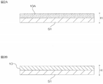
- 2A and 2B show some steps in one embodiment of the method for producing a joined sheet of the present invention.
- FIG. 2A represents the coating film forming process
- FIG. 2B represents the drying process.
- 3A to 3C are process diagrams of an example of a solder bonding method using the bonding sheet shown in FIG. 3A represents the preparation process
- FIG. 3B represents the lamination process
- FIG. 3C represents the heating process.
- FIG. 4 is a scanning electron microscope (SEM) image processing diagram of a cross section of the bonded sheet of Example 1.
- FIG. 5 is a scanning electron microscope (SEM) image processing diagram of the cross section of the joint sheet of Comparative Example 1.
- FIG. 6 is an energy dispersive X-ray analysis (EDX) image processing diagram of the cross section of the joining sheet of Example 1.
- FIG. 7A to 7C are scanning electron microscope (SEM) image processing diagrams of cross sections of the joint sheets of Example 1 and Comparative Example 2 for evaluating uneven distribution of flux.
- 7A and 7B are scanning electron microscope (SEM) image processing views of the cross section of the bonded sheet of Example 1.
- FIG. 7C is a scanning electron microscope (SEM) image processing diagram of the cross section of the joint sheet of Comparative Example 2.
- FIG. 1 is a schematic cross-sectional view of a joining sheet 10 as one embodiment of the joining sheet of the present invention (illustrating a state in which the joining sheet 10 is sandwiched between base materials S1 and S2).
- the joining sheet 10 is used for soldering two objects to be joined.
- the joining sheet 10 has a sheet shape with a predetermined thickness and extends in a direction perpendicular to the thickness direction H (plane direction).
- the joining sheet 10 may have a long sheet shape. When the joining sheet 10 has a long sheet shape, it may have the form of a wound roll. Alternatively, the joining sheet 10 may have a sheet form.
- the thickness of the joining sheet is, for example, 30 ⁇ m or less, preferably 25 ⁇ m or less, more preferably 20 ⁇ m or less, and even more preferably 15 ⁇ m or less.
- the thickness of the joining sheet is, for example, 3 ⁇ m or more, preferably 5 ⁇ m or more, from the viewpoint of handling properties of the joining sheet.
- the joining sheet contains matrix resin, solder particles, and fluxing agent.
- the matrix resin contains a thermosetting resin and a thermoplastic resin.
- the thermosetting resin is preferably liquid at room temperature (25°C)
- the thermoplastic resin is solid at room temperature (25°C).
- thermosetting resins examples include epoxy resins, urea resins, melamine resins, diallyl phthalate resins, silicone resins, phenol resins, thermosetting acrylic resins, thermosetting polyesters, thermosetting polyimides, and thermosetting polyurethanes. be done. Epoxy resins and thermosetting polyurethanes are preferred, and epoxy resins are more preferred.
- Epoxy resins include, for example, aromatic epoxy resins, nitrogen-containing ring epoxy resins, aliphatic epoxy resins, alicyclic epoxy resins, glycidyl ether type epoxy resins, and glycidyl amine type epoxy resins.
- aromatic epoxy resins include bisphenol-type epoxy resins, novolac-type epoxy resins, fluorene-type epoxy resins, and triphenylmethane-type epoxy resins.
- bisphenol-type epoxy resins include bisphenol A-type epoxy resin, bisphenol F-type epoxy resin, bisphenol S-type epoxy resin, hydrogenated bisphenol A-type epoxy resin, and dimer acid-modified bisphenol-type epoxy resin.
- novolak-type epoxy resins examples include phenol novolac-type epoxy resins, cresol novolak-type epoxy resins, and biphenyl-type epoxy resins.
- fluorene-type epoxy resins examples include bisarylfluorene-type epoxy resins.
- triphenylmethane-type epoxy resins examples include trishydroxyphenylmethane-type epoxy resins.
- Nitrogen-containing ring epoxy resins include, for example, triepoxypropyl isocyanurate (triglycidyl isocyanurate) and hydantoin epoxy resins.
- Alicyclic epoxy resins include, for example, dicyclocyclic epoxy resins.
- epoxy resins can be used. Specifically, jER (registered trademark) 828 (bisphenol A type epoxy resin, manufactured by Mitsubishi Chemical Corporation) is used.
- the epoxy equivalent of the epoxy resin is, for example, 80 g/eq or more, preferably 100 g/eq or more, more preferably 150 g/eq or more, and for example, 500 g/eq or less, preferably 400 g/eq. or less, more preferably 250 g/eq or less.
- the epoxy resin preferably a bisphenol type epoxy resin that is liquid at room temperature (25°C), more preferably a bisphenol A type epoxy resin that is liquid at room temperature (25°C) is used.
- the curing temperature of the thermosetting resin is, for example, 90°C or higher, preferably 140°C or higher, and is, for example, 250°C or lower, preferably 230°C or lower, and more preferably 200°C. or less, more preferably 160° C. or less.
- thermosetting resin is preferably liquid at room temperature (25°C). Adhesion reliability increases if the thermosetting resin is liquid at room temperature.
- liquid refers to a liquid or fluid having a viscosity of 200 Pa ⁇ s or less at room temperature (25°C).
- thermosetting resins can be used alone or in combination of two or more.
- the proportion of the thermosetting resin in the matrix resin is, for example, 50% by mass or more, preferably 60% by mass or more, and 90% by mass or less, preferably 80% by mass or less. Further, the proportion of the thermosetting resin in the joining sheet is, for example, 10% by mass or more, preferably 20% by mass or more, and 50% by mass or less, preferably 30% by mass or less. If the proportion of the thermosetting resin is less than the above lower limit, a sufficient reinforcing effect may not be obtained after soldering. On the other hand, if this ratio exceeds the above upper limit, it may be difficult to form a sheet.
- the matrix resin may further contain a phenol resin as a curing agent for the epoxy resin.
- phenolic resins include, for example, novolak-type phenolic resins and resol-type phenolic resins.
- Novolac-type phenolic resins include, for example, phenol novolak resins, phenol aralkyl resins, cresol novolac resins, tert-butylphenol novolak resins, and nonylphenol novolak resins.
- thermoplastic resins include polyolefins (eg, polyethylene, polypropylene and ethylene-propylene copolymers), acrylic resins, phenoxy resins, polyesters, polyvinyl acetates, ethylene-vinyl acetate copolymers, polyvinyl chloride, polystyrene, Polyacrylonitrile, polyamide (nylon (registered trademark)), polycarbonate, polyacetal, polyethylene terephthalate, polyphenylene oxide, polyphenylene sulfide, polysulfone, polyethersulfone, polyetheretherketone, polyarylsulfone, thermoplastic polyimide, thermoplastic polyurethane, polyaminobis Maleimide, polyamideimide, polyetherimide, bismaleimide triazine resin, polymethylpentene, fluorinated resin, liquid crystal polymer, olefin-vinyl alcohol copolymer, ionomer, polyarylate, acrylonitrile-ethylene-ethylene
- the thermoplastic resin preferably includes acrylic resin and polyester, more preferably acrylic resin.
- Acrylic resins consist of acrylic polymers, such acrylic polymers are, for example, methyl (meth)acrylate, ethyl (meth)acrylate, propyl (meth)acrylate, butyl (meth)acrylate, (meth)acrylic Monomer containing alkyl (meth)acrylate ester having an alkyl moiety having 1 to 12 carbon atoms such as hexyl acid, octyl (meth)acrylate, decyl (meth)acrylate, and dodecyl (meth)acrylate as a main component. It is a polymer.
- “(Meth)acrylic acid” means acrylic acid and/or methacrylic acid. Monomers can be used alone or in combination.
- the monomer may contain one or more copolymerizable monomers copolymerizable with the (meth)acrylic acid alkyl ester.
- Copolymerizable monomers include functional group-containing vinyl monomers and aromatic vinyl monomers.
- the copolymerizable monomer helps modify the acrylic polymer, such as ensuring cohesive strength of the acrylic polymer.
- Examples of functional group-containing vinyl monomers include carboxy group-containing vinyl monomers, acid anhydride vinyl monomers, hydroxyl group-containing vinyl monomers, sulfo group-containing vinyl monomers, phosphoric acid group-containing vinyl monomers, cyano group-containing vinyl monomers, and glycidyl group-containing vinyl monomers.
- Vinyl monomers are mentioned.
- a hydroxyl group-containing vinyl monomer is used.
- Aromatic vinyl monomers include, for example, styrene, chlorostyrene, chloromethylstyrene, and ⁇ -methylstyrene.
- acrylic polymer Commercially available products can be used as the acrylic polymer. Specifically, UH-2170 (manufactured by Toagosei Co., Ltd.) can be mentioned as a hydroxyl group-containing styrene acrylic polymer.
- the glass transition temperature Tg of the acrylic resin is, for example, -100°C or higher, preferably -50°C or higher, and is, for example, 100°C or lower, preferably 50°C or lower.
- the glass transition temperature (Tg) of acrylic resin is obtained based on the Fox formula.
- the softening temperature of the thermoplastic resin is, for example, 40° C. or higher, preferably 45° C. or higher, more preferably 50° C. or higher, and most preferably 55° C. or higher.
- °C or lower preferably 120 °C or lower, more preferably 100 °C or lower, most preferably 80 °C or lower.
- the weight average molecular weight (Mw) of the thermoplastic resin is, for example, 8,000 or more, preferably 10,000 or more, and is, for example, 2 million or less, preferably 1,500,000 or less.
- the weight average molecular weight (standard polystyrene conversion value) of the acrylic resin is calculated by GPC. When the weight-average molecular weight (Mw) is within the above range, it is possible to suppress the formation of pinholes when forming into a sheet.
- thermoplastic resin is preferably solid (solid) at room temperature (25°C). If the thermoplastic resin is solid at room temperature, it is possible to ensure shape retention and maintain the sheet shape of the joined sheet.
- thermoplastic resins can be used singly or in combination of two or more.
- the proportion of the thermoplastic resin in the matrix resin is, for example, 10% by mass or more, preferably 20% by mass or more, and 50% by mass or less, preferably 40% by mass or less. Further, the proportion of the thermoplastic resin in the joining sheet is preferably 2% by mass or more, more preferably 5% by mass or more, still more preferably 10% by mass or more, and is preferably 50% by mass or less, more preferably 30% by mass. % by mass or less, more preferably 20% by mass or less. Within the above range, both the moldability of the bonding sheet and the bonding strength of the bonding sheet to the bonding target can be achieved.
- thermosetting resin In the matrix resin, the thermosetting resin and the thermoplastic resin are compatible with each other.
- solder material that forms the solder particles is, for example, solder metal.
- Solder metals include solder materials that do not contain lead (lead-free solder) from the viewpoint of environmental suitability.
- solder materials include, for example, tin-bismuth based alloys and tin-silver based alloys.
- Tin-bismuth alloys include, for example, tin-bismuth alloys (Sn-Bi) and tin-bismuth-indium alloys (Sn-Bi-In).
- Tin-silver alloys include, for example, tin-silver alloys (Sn-Ag) and tin-silver-copper alloys (Sn-Ag-Cu). From the standpoint of low temperature bonding, the solder material preferably includes tin-bismuth alloys and tin-bismuth-indium alloys.
- the content of tin in the tin-bismuth alloy is, for example, 20% by mass or more, preferably 30% by mass or more, and is, for example, 50% by mass or less, preferably 45% by mass or less.
- the content of bismuth in the tin-bismuth alloy is, for example, 50% by mass or more, preferably 55% by mass or more, and, for example, 80% by mass or less, preferably 70% by mass or less. .
- the melting point of the solder particles is, for example, 100° C. or higher, preferably 130° C. or higher, and is, for example, 240° C. or lower, preferably 200° C. or lower, more preferably 160° C. or lower. and more preferably 150° C. or less.
- the melting point of the solder material can be determined by differential scanning calorimetry (DSC) (hereinafter, the same applies to flux agents). If the melting point of the solder particles is within the above range, it is possible to suppress the melting of the solder in the heating process during sheet formation. In addition, it is possible to suppress the influence of heat applied to the periphery of the mounting portion during mounting by soldering.
- the shape of the solder particles includes, for example, a spherical shape, a plate shape, and a needle shape, preferably a spherical shape.
- the median diameter (particle diameter) D50 of the solder particles is, for example, 10 nm or more, preferably 1 ⁇ m or more.
- the particle diameter D50 of the solder particles is, for example, 10 ⁇ m or less, preferably 8 ⁇ m or less, more preferably 6 ⁇ m or less, even more preferably 5 ⁇ m or less, particularly preferably 4 ⁇ m or less.
- the particle diameter D50 is equal to or less than the above upper limit, the dispersibility of the solder particles in the joining sheet can be improved. In addition, it is possible to reduce the thickness of the joining sheet.
- the particle diameter D50 of the solder particles is the median diameter in the volume-based particle size distribution (particle size at which the volume cumulative frequency reaches 50% from the small diameter side), for example, based on the particle size distribution obtained by the laser diffraction/scattering method (The same applies to fluxing agents below).
- the surface of the solder particles is generally covered with an oxide film made of oxide of the solder material.
- the thickness of the oxide film is, for example, 1 to 20 nm.
- the oxygen concentration of the solder particles can be measured by a known method, for example, by a nitrogen/oxygen simultaneous analyzer (EMGA-650, manufactured by Horiba, Ltd.).
- the oxygen concentration of the solder particles is preferably low.
- the oxygen concentration of the solder particles is, for example, 100 ppm or more, preferably 350 ppm or more, more preferably 550 ppm or more, more preferably 700 ppm or more, and for example, 3000 ppm or less, preferably 2500 ppm or less. , more preferably 2000 ppm or less, still more preferably 1400 ppm or less.
- the oxygen concentration of the solder particles is within the above range, the solder particles can be efficiently accumulated.
- solder particles can be used singly or in combination of two or more.
- the content of the solder particles in the joining sheet is, for example, 50 parts by mass or more, preferably 100 parts by mass or more, more preferably 120 parts by mass or more with respect to 100 parts by mass of the matrix resin.
- the proportion of solder particles in the bonding sheet is, for example, 5% by mass or more, preferably 10% by mass or more, more preferably 20% by mass or more, still more preferably 30% by mass or more, particularly preferably 40% by mass or more, and most preferably 40% by mass or more. Preferably, it is 50% by mass or more.
- the content of the solder particles is at least the above lower limit, cohesiveness of the solder particles in the soldering process can be ensured.
- the content of the solder particles in the joining sheet is, for example, 600 parts by mass or less, preferably 450 parts by mass or less, more preferably 170 parts by mass or less with respect to 100 parts by mass of the matrix resin.
- the proportion of solder particles in the joining sheet is, for example, 80% by mass or less, preferably 70% by mass or less, and more preferably 60% by mass or less. When the content of the solder particles is equal to or less than the above upper limit, the formability of the joining sheet is excellent.
- the solder particles are evenly dispersed in the matrix resin. That is, the solder particles are distributed uniformly in the matrix resin.
- the "uniform concentration" has a distribution width of ⁇ 20%, preferably ⁇ 10%, with respect to the standard concentration based on the content of the solder particles in the matrix resin.
- the concentration distribution can be observed, for example, with a scanning electron microscope (SEM).
- the flux agent removes (activates) the oxide film on the surface of the solder particles when the solder particles are melted by heating.
- Examples of fluxing agents include organic acids, quinolinol derivatives, and metal carbonyl salts.
- Organic acids include, for example, carboxylic acids.
- Carboxylic acids include monocarboxylic acids, dicarboxylic acids, and tricarboxylic acids.
- Monocarboxylic acids include, for example, glycolic acid, lactic acid, and 2-hydroxybutanoic acid.
- Dicarboxylic acids include, for example, tartaric acid, malic acid, adipic acid, malonic acid, succinic acid, glutaric acid, pimelic acid, suberic acid, and sebacic acid.
- Tricarboxylic acids include, for example, citric acid.
- the fluxing agent is preferably carboxylic acid, more preferably dicarboxylic acid, and still more preferably malic acid and malonic acid.
- the fluxing agent is preferably solid at 25°C.
- the melting point of the fluxing agent is higher than 25°C, preferably 80°C or higher, more preferably 100°C or higher, and even more preferably 120°C or higher.
- the melting point of the fluxing agent is, for example, 200° C. or lower, preferably 180° C. or lower, more preferably 160° C. or lower.
- the fluxing agent is preferably a carboxylic acid that is solid at 25°C.
- the shape of the flux agent is not particularly limited, and examples thereof include a plate shape, a needle shape, and a spherical shape.
- the particle diameter D50 of the fluxing agent is, for example, 2 ⁇ m or more, preferably 3 ⁇ m or more, and is, for example, 20 ⁇ m or less, preferably 10 ⁇ m or less, and more preferably 6 ⁇ m or less. If the particle diameter D50 of the fluxing agent is within the above range, the dispersibility of the fluxing agent can be improved.
- These flux agents can be used alone or in combination of two or more.
- the content of the fluxing agent in the bonding sheet is, for example, 1 part by mass or more, preferably 5 parts by mass or more, more preferably 7.5 parts by mass or more, and still more preferably 10 parts by mass or more with respect to 100 parts by mass of the matrix resin. is. Also, the proportion of the fluxing agent in the joining sheet 10 is, for example, 1% by mass or more, preferably 2% by mass or more, and more preferably 3% by mass or more. When the content of the fluxing agent is at least the above lower limit, cohesiveness of the solder particles can be ensured during the soldering process.
- the content of the fluxing agent in the joining sheet is, for example, 50 parts by mass or less, preferably 20 parts by mass or less, more preferably 17.5 parts by mass or less, and even more preferably 15 parts by mass with respect to 100 parts by mass of the matrix resin. parts, particularly preferably 12.5 parts by mass or less, most preferably 10 parts by mass or less.
- the proportion of the fluxing agent in the joining sheet is, for example, 50% by mass or less, preferably 20% by mass or less, more preferably 10% by mass or less, even more preferably 8% by mass or less, particularly preferably 7% by mass or less, and most preferably. is 5% by mass or less. When the content of the fluxing agent is equal to or less than the above upper limit, the formability of the bonded sheet is excellent.
- the bonding sheet preferably satisfies the following formula (1), where x 1 ppm is the oxygen concentration of the solder particles, and y 1 mmol is the content of the fluxing agent with respect to 100 parts by weight of the solder particles. 0.045 ⁇ y1/ x1 ⁇ 0.090 ( 1 )
- y 1 /x 1 is, for example, 0.045 or more, preferably 0.050 or more, and, for example, 0.099 or less, preferably 0.090 or less, more preferably is less than or equal to 0.080.
- y 1 /x 1 is within the above range, solder particles are likely to accumulate, and surplus acid is small, so it is possible to suppress an increase in resistance value due to corrosion of the solder portion after connection.
- the bonding sheet preferably satisfies the following formula (2), where x 2 ⁇ m is the median diameter (D 50 ) of the solder particles, and y 2 mol is the content of the fluxing agent with respect to 100 parts by weight of the solder particles. . 0.150 ⁇ x2y2 ⁇ 0.300 ( 2 )
- x 2 y 2 is, for example, 0.150 or more, preferably 0.155 or more, more preferably 0.157 or more, and for example, 0.314 or less, preferably , is 0.300 or less, more preferably 0.270 or less.
- x 2 y 2 is within the above range, solder particles are likely to accumulate, and surplus acid is small, so it is possible to suppress an increase in resistance value caused by corrosion of the solder portion after connection.
- the flux agent is unevenly distributed around the solder particles in the matrix resin. That is, the flux agent is distributed in the matrix resin such that the concentration around the solder particles is higher than the concentration around the solder particles.
- “surrounding the solder particles” specifically refers to a range of twice, preferably 1.5 times the diameter of the solder particles, and "the concentration around the solder particles is higher than the concentration other than the solder particles”.
- “Also high” means that the surrounding maximum density is twice, preferably five times the minimum density other than the surroundings. The concentration distribution can be confirmed, for example, with a scanning electron microscope (SEM).
- the flux agent is unevenly distributed around the solder particles in this way, the oxide film on the surface of the solder particles can be efficiently removed, and the solder particles can be agglomerated. Moreover, since the flux agent is unevenly distributed around the solder particles, excess flux agent other than around the solder particles can be reduced, and an increase in the resistance value of the solder portion can be suppressed.
- the fluxing agent unevenly distributed around the solder particles preferably contains a metal derived from the solder particles.
- the metal derived from the solder particles corresponds to the type of solder particles (solder metal) contained.
- solder metal solder metal
- Methods for measuring metals derived from solder particles include, for example, energy dispersive X-ray spectroscopy (EDX).
- the content of the solder particles in the flux agent is, for example, 50 parts by mass or more, preferably 100 parts by mass or more, and for example, 500 parts by mass or less with respect to 100 parts by mass of the matrix resin, Preferably, it is 300 parts by mass or less. If the content of the solder particles is within the above range, the oxide film of the solder particles can be efficiently removed, and the solder particles can be accumulated without forming bridges on the electrodes.
- the bonding sheet of the present invention may optionally include, for example, a curing agent and/or curing accelerator for thermosetting resins, and silane coupling from the viewpoint of improving the adhesion strength between solder particles and thermoplastic resins.
- Additives such as agents can be contained in appropriate proportions.
- the joining sheet can be manufactured by the following manufacturing method.
- This manufacturing method is an embodiment of the bonded sheet manufacturing method of the present invention.
- the first solvent is a solvent capable of dissolving the fluxing agent, and is selected according to the type of fluxing agent.
- the first solvent is not limited as long as it dissolves the fluxing agent.
- First solvents include, for example, water, alcohols, carboxylic acids, and ketones.
- Alcohols include, for example, methanol, ethanol, isopropyl alcohol, and butanol.
- Carboxylic acids include formic acid and acetic acid.
- Ketones include, for example, acetone, methyl ethyl ketone and methyl isobutyl ketone.
- the first solvent is preferably an alcohol or a ketone, more preferably acetone.
- the fluxing agent concentration (non-volatile component concentration) of the fluxing agent solution is, for example, 10% by mass or more, preferably 20% by mass or more, more preferably 25% by mass, from the viewpoint of miscibility with other components in the following second step. % or more, and for example, 50% by mass or less, preferably 40% by mass or less, more preferably 35% by mass or less.
- the second solvent is preferably a solvent in which at least part of the fluxing agent dissolves.
- Second solvents include, for example, ketones, alkyl esters, aliphatic hydrocarbons, and aromatic hydrocarbons. Ketones are preferred. Ketones include, for example, acetone, methyl ethyl ketone, methyl isobutyl ketone, and cyclohexanone.
- Alkyl esters include, for example, methyl acetate, ethyl acetate, butyl acetate, isobutyl acetate, and amyl acetate.
- Aliphatic hydrocarbons include, for example, n-hexane, n-heptane, octane, cyclohexane, and methylcyclohexane.
- Aromatic hydrocarbons include, for example, toluene, xylene, and ethylbenzene.
- the second solvent may be used alone, or two or more of them may be used in combination.
- the second solvent may be of the same type as the first solvent, or may be of a different type.
- the solid content concentration of the mixed composition is, for example, 50% by mass or more, preferably 60% by mass or more, more preferably 65% by mass or more, from the viewpoint of ease of forming a coating film in the following third step. Also, for example, it is 90% by mass or less, preferably 80% by mass or less, more preferably 75% by mass or less.
- the mixed composition is applied onto the substrate S1 to form a coating film 10A, and then, as shown in FIG. 2B, the coating film 10A is dried to form the joining sheet 10.
- the substrate S1 include a plastic film.
- the plastic film include polyethylene terephthalate film, polyethylene film, polypropylene film, and polyester film.
- the surface of the base material is preferably surface release treated.
- the joining sheet 10 is dried by heating.
- the drying temperature is equal to or higher than the softening temperature of the thermoplastic resin, lower than the melting points of the solder particles and the fluxing agent, and lower than the curing temperature of the thermosetting resin.
- the drying temperature is preferably 60° C. or higher, more preferably 75° C. or higher, and preferably 130° C. or lower, more preferably 120° C. or lower.
- the base material S2 may be laminated on the joining sheet 10 on the base material S1.
- the plastic film described above for the substrate S1 can be used (FIG. 1 illustrates a state in which the joining sheet 10 is sandwiched between the substrates S1 and S2).
- the joining sheet 10 can be manufactured as described above.
- the flux agent is dissolved in the first solvent in the first step.
- the fluxing agent is dissolved in the first solvent and mixed with other components (matrix resin component, solder particles). Therefore, in the coating film formed in the third step, the flux agent is unevenly distributed around the solder particles in the matrix resin. As a result, the oxide film on the surface of the solder particles can be efficiently removed and the solder particles can be agglomerated.
- the flux agent is unevenly distributed around the solder particles, it is possible to reduce the amount of excess flux agent other than around the solder particles, thereby suppressing an increase in the resistance value of the solder portion.
- FIG. 3 shows an example of a solder joint method using the joint sheet 10.
- a printed circuit board 30, an electronic component 40, and a joining sheet 10 are prepared (preparation step).
- the wired circuit board 30 is an example of one bonding object, and has a substrate 31 and a plurality of terminals 32 .
- the substrate 31 is, for example, an insulating substrate having a flat plate shape.
- the terminal 32 is made of metal.
- the multiple terminals 32 are separated from each other.
- the maximum length of the terminal 32 is, for example, 10 ⁇ m or more and, for example, 200 ⁇ m or less.
- the interval between terminals 32 is, for example, 10 ⁇ m or more and, for example, 200 ⁇ m or less.
- the electronic component 40 is an example of the other object to be joined, and has a body portion 41 and a plurality of terminals 42 .
- the terminal 42 is made of metal.
- the plurality of terminals 42 are separated from each other.
- the plurality of terminals 42 are arranged and sized to face the plurality of terminals 32 of the printed circuit board 30 .
- solder particles 11 and matrix resin 12 are illustrated.
- the wired circuit board 30, the joining sheet 10, and the electronic component 40 are laminated in this order (lamination step). Specifically, the wiring circuit board 30 and the electronic component 40 are arranged so that the corresponding terminals 32 , 42 face each other, and the bonding sheet 10 is placed so that the terminals 32 , 42 are embedded in the bonding sheet 10 . crimp through. Thereby, the laminated body W is obtained. The printed circuit board 30 and the electronic component 40 are temporarily joined via the joining sheet 10 .
- the heating temperature is a temperature above the melting point of the solder particles 11 and the flux agent, a temperature above the softening point of the thermoplastic resin, and a temperature above the curing temperature of the thermosetting resin.
- the heating temperature is appropriately determined depending on the type of thermosetting resin, thermoplastic resin, solder particles and fluxing agent, and is, for example, 120°C or higher, preferably 130°C or higher, or, for example, 170°C. or less, preferably 160° C. or less.
- the heating time is, for example, 3 seconds or more, and is, for example, 60 seconds or less, preferably 30 seconds or less.
- thermoplastic resin is once melted in the joining sheet 10, and the flux agent is melted to exhibit the function of removing the oxide film on the surface of the solder particles.
- the solder particles are melted, agglomerated, gathered between the terminals 32 and 42 and agglomerated (self-alignment).
- Curing of the thermosetting resin proceeds around the condensed solder material.
- the solder material that has aggregated between the terminals 32 and 42 solidifies to form the solder portion 11A.
- the printed circuit board 30 and the electronic component 40 are joined by the joining sheet 10, and the terminals 32 and 42 are electrically connected by the solder portion 11A.
- a cured resin portion 12A derived from the matrix resin 12 is formed around the solder portion 11A.
- the cured resin portion 12A contains at least partially cured thermosetting resin and solidified thermoplastic resin, and preferably contains the completely cured thermosetting resin and the solidified thermoplastic resin. .
- the electronic component 40 can be mounted on the wired circuit board 30 using the joining sheet 10 .
- the flux agent is evenly dispersed throughout the matrix resin (thermoplastic resin and thermosetting resin) as well as around the solder particles.
- the bonding sheet flux agents other than the flux agent that exists around the solder particles and contributes to the removal of the oxide film of the solder particles do not exist around the solder particles and do not contribute to the removal of the oxide film of the solder particles. Excess fluxing agent is present. In this case, since the solder particles dispersed throughout the matrix resin need to reach the surface of the solder particles, the required amount of the flux agent is become more. As a result, there is a problem that the resistance value increases due to metal corrosion of the solder portion due to the excessive flux agent.
- the flux agent 13 is unevenly distributed around the solder particles 11 in the matrix resin 12, as shown in the enlarged view of FIG. Therefore, the amount of excess flux other than the flux necessary for efficiently removing the oxide film on the surface of the solder particles can be reduced. As a result, it is possible to suppress an increase in the resistance value of the solder portion due to excess flux. As a result, durability can be improved.
- the flux agent is dissolved in the first solvent in the first step. Therefore, as the joining sheet 10 dries, the flux agent is unevenly distributed around the solder particles in the matrix resin. As a result, the total amount of required fluxing agent can be suppressed, and an increase in the resistance value of the solder portion can be suppressed.
- the bonding sheet 10 is arranged between the electronic component 40 and the wired circuit board 30.
- the joining sheet 10 is laminated on one of the wired circuit boards 30 so that the terminals 32 of the wired circuit board 30 are in contact with each other, and then the electronic component 40 is placed on the joining sheet 10. It is also possible to laminate such that the terminals 42 are in contact with the joining sheet 10 . In other words, the joining sheet 10 and the electronic component 40 can be sequentially laminated on the wiring circuit board 30 on one side.
- the electronic component is manufactured by bonding the electronic component 40 and the wired circuit board 30 with the bonding sheet 10.
- the wired circuit board 30 and another wired circuit board may be bonded with the bonding sheet 10. It is also possible to manufacture electronic components.
- Example 1 A bonded sheet of Example 1 was produced as follows.
- an epoxy resin (trade name “jER828”, bisphenol A type epoxy resin, epoxy equivalent 184 to 194 g / eq, liquid at room temperature (25 ° C.), manufactured by Mitsubishi Chemical Corporation) as a thermosetting resin 60 parts by mass
- Acrylic resin (trade name “ARUFON UH-2170”, hydroxyl group-containing styrene acrylic polymer, solid at room temperature (25 ° C.), manufactured by Toagosei Co., Ltd.) as a thermoplastic resin 40 parts by mass
- solder particles 42 mass% Sn-58 mass% Bi alloy, melting point 139°C, spherical shape, particle size D50 is 3 ⁇ m, oxygen concentration 1100 ppm) and 150 parts by mass of fluxing agent solution were added to methyl ethyl ketone (MEK) and mixed to obtain a solid content concentration of 72 mass%. was prepared (second step).
- the content of the fluxing agent in this mixed composition was 10 parts by mass.
- composition of the joining sheet of Example 1 is shown in Table 1 (compositions of joining sheets of Examples and Comparative Examples below are also shown in Tables 1 and 2).
- Tables 1 and 2 the unit of each numerical value representing the composition of the composition is relative "parts by weight”.
- Example 2 In the second step, the amount of the fluxing agent (malic acid) in the mixed composition was changed from 10 parts by mass to 17.5 parts by mass to prepare a mixed composition with a solid content concentration of 63% by mass (second step ), a bonded sheet was produced in the same manner as the bonded sheet of Example 1, except for the above.
- the fluxing agent malic acid
- Example 3 In the second step, the amount of the fluxing agent (malic acid) in the mixed composition was changed from 10 parts by mass to 20 parts by mass to prepare a mixed composition with a solid content concentration of 61% by mass (second step).
- a bonded sheet of Example 3 was produced in the same manner as the bonded sheet of Example 1 except for the above.
- Example 4 In the first step, instead of malic acid as a fluxing agent, malonic acid (particle size D50 : 4.5 ⁇ m, melting point: 135° C., solid at room temperature (25° C.)) is used, and in the second step, mixing Instead of 10 parts by mass of the fluxing agent (malonic acid) in the composition, 10 parts by mass of the fluxing agent (malonic acid) was used to prepare a mixed composition having a solid content concentration of 72% by mass (second step). A bonded sheet of Example 4 was produced in the same manner as the bonded sheet of Example 1.
- Example 5 In the first step, malonic acid is used instead of malic acid as a fluxing agent, and in the second step, 10 parts by mass of the fluxing agent (malonic acid) in the mixed composition is replaced with a fluxing agent (malonic acid).
- a bonding sheet of Example 5 was produced in the same manner as the bonding sheet of Example 1, except that a mixed composition having a solid content concentration of 61% by mass was prepared (second step).
- Example 6 In the second step, as the solder particles in the mixed composition, solder particles (42% by mass Sn-58% by mass Bi alloy, melting point 139 ° C., spherical shape, particle diameter D 50 is 5 ⁇ m, oxygen concentration 650 ppm), A joining sheet of Example 6 was produced in the same manner as the joining sheet of Example 1, except that a mixed composition having a solid content concentration of 72% by mass was prepared (second step).
- Example 7 In the second step, instead of 10 parts by mass of the fluxing agent (malic acid) in the mixed composition, 17.5 parts by mass of the fluxing agent (malic acid) is used, and solder particles (42 parts by mass) are used as the solder particles in the mixed composition. % Sn-58% by mass Bi alloy, melting point 139° C., spherical shape, particle size D50 3 ⁇ m, oxygen concentration 1500 ppm), and a mixed composition with a solid content concentration of 61% by mass was prepared (second step). A bonded sheet of Example 7 was produced in the same manner as the bonded sheet of Example 1 except for the above.
- Example 8 In the second step, instead of 10 parts by mass of the fluxing agent (malic acid) in the mixed composition, 20 parts by mass of the fluxing agent (malic acid) is used, and the solder particles in the mixed composition are solder particles (42% by mass of Sn ⁇ 58% by mass Bi alloy, melting point 139° C., spherical shape, particle size D50 3 ⁇ m, oxygen concentration 1500 ppm), and a mixed composition with a solid content concentration of 61% by mass was prepared (second step) A bonded sheet of Example 8 was prepared in the same manner as the bonded sheet of Example 1.
- solder particles 42 mass% Sn-58 mass% Bi alloy, melting point 139 ° C., spherical shape, particle diameter D50 is 3 ⁇ m, oxygen concentration 300 ppm
- a joining sheet of Example 9 was produced in the same manner as the joining sheet of Example 1, except that a mixed composition having a solid content concentration of 61% by mass was prepared (second step).
- solder particles (42% by mass Sn-58% by mass Bi alloy, melting point 139° C., spherical shape, particle diameter D 50 is 7 ⁇ m, oxygen concentration 500 ppm) are used as the solder particles in the mixed composition
- a joining sheet of Example 10 was produced in the same manner as the joining sheet of Example 1, except that a mixed composition having a solid content concentration of 72% by mass was prepared (second step).
- Epoxy resin (trade name “jER828”, bisphenol A type epoxy resin, epoxy equivalent 184 to 194 g / eq, liquid at room temperature (25 ° C.), manufactured by Mitsubishi Chemical Corporation) as a thermosetting resin, 60 parts by mass, and a thermoplastic resin 40 parts by mass of acrylic resin (trade name “ARUFON UH-2170”, hydroxyl group-containing styrene acrylic polymer, solid at room temperature (25 ° C.), manufactured by Toagosei Co., Ltd.) and solder particles (42 mass% Sn-58 mass% Bi 150 parts by mass of alloy, melting point 139°C, spherical shape, particle diameter D50 is 3 ⁇ m, oxygen concentration 1100 ppm) and 50 parts by mass of fluxing agent (malic acid) were added to methyl ethyl ketone (MEK) and mixed to obtain a solid content concentration of A 70 wt% mixed composition was prepared.
- epoxy resin trade name “jER828”, bisphenol A type epoxy resin,
- the coating film was dried (third step).
- the drying temperature was 80° C. and the drying time was 5 minutes. As a result, a bonding sheet having a thickness of 10 ⁇ m was formed on the substrate (release liner).
- Sample cross-sections were prepared as follows. Using an FIB-SEM apparatus (“Helios G4 UX”, manufactured by Thermo Fisher Scientific), the cross section of the sample was adjusted by irradiating a Ga ion beam under conditions of an acceleration voltage of 30 kV and a temperature of ⁇ 160° C. A backscattered electron image of the cross-section of the bonded sheet prepared as described above was obtained using an FIB-SEM device (“Helios G4 UX”, manufactured by Thermo Fisher Scientific) under the conditions of an acceleration voltage of 2 kV and a temperature of ⁇ 160° C. Obtained.
- FIB-SEM apparatus Helios G4 UX
- FIG. 1 A scanning electron microscope (SEM) image processing diagram of Example 1 is shown in FIG.
- solder particles 11 were dispersed in the matrix resin 12, and the flux agent 13 was unevenly distributed around the solder particles 11 in the matrix resin 12.
- the solder particles 11 are dispersed in the matrix resin 12, but the flux agent 13 is not unevenly distributed around the solder particles 11 in the matrix resin 12.
- the middle upper diagram in FIG. 6 shows a scanning electron microscope (SEM) image processing diagram of the cross section of the bonding sheet of Example 1.
- the diagram on the upper right side of FIG. 6 is an energy dispersive X-ray analysis (EDX) image processing diagram showing the presence or absence of inclusion of metals (Bi, Sn) derived from the solder particles 11 in the matrix resin 12 portion. As shown in the upper right diagram of FIG. 6, metals (Bi, Sn) derived from the solder particles 11 were not detected in the matrix resin 12 portion.
- EDX energy dispersive X-ray analysis
- the diagram on the lower right side of FIG. 6 is an image processing diagram of energy dispersive X-ray analysis (EDX) showing the presence or absence of metal (Bi, Sn) contained in the solder particles 11 in the solder particles 11 portion. As shown in the lower right diagram of FIG. 6 , Sn, which is the metal of the solder particles 11 , was detected in the Sn-rich phase of the solder particles 11 .
- EDX energy dispersive X-ray analysis
- the lower center diagram of FIG. 6 is an image processing diagram of energy dispersive X-ray analysis (EDX) showing the presence or absence of metal (Bi, Sn) contained in the solder particles 11 in the solder particles 11 portion. As shown in the lower center diagram of FIG. 6 , Bi, which is the metal of the solder particles 11 , was detected in the Bi-rich phase of the solder particles 11 .
- EDX energy dispersive X-ray analysis
- the lower left diagram of FIG. 6 is an energy dispersive X-ray analysis (EDX) image processing diagram showing the presence or absence of inclusion of metals (Bi, Sn) derived from the solder particles 11 in the flux agent 13 portion. As shown in the lower left diagram of FIG. 6, metals (Bi, Sn) derived from the solder particles 11 were detected in the flux agent 13 portion.
- EDX energy dispersive X-ray analysis
- the upper left diagram of FIG. 6 is an energy dispersive X-ray analysis (EDX) image processing diagram showing the presence or absence of inclusion of metals (Bi, Sn) derived from the solder particles 11 in the flux agent 13 portion. As shown in the upper left diagram of FIG. 6, metals (Bi, Sn) derived from the solder particles 11 were detected in the flux agent 13 portion.
- EDX energy dispersive X-ray analysis
- Each bonding sheet was evaluated for the accumulation of solder particles by heating.
- a sample was prepared by bonding two printed circuit boards together via a bonding sheet.
- Each wired circuit board has a transparent glass substrate and a plurality of terminals (30 ⁇ m wide) formed thereon. A plurality of terminals are arranged in parallel on one surface of the glass substrate (the space between adjacent terminals is 30 ⁇ m).
- two printed circuit boards are joined via a joining sheet so that the terminals of one printed circuit board face the terminals of the other printed circuit board.
- the samples were then heat treated at 160°C for 30 seconds.
- Each bonded sheet was evaluated for durability by resistance value measurement as follows. First, two printed circuit boards were bonded together via a bonding sheet to prepare a sample. Each wired circuit board has a transparent glass substrate and a plurality of terminals (30 ⁇ m wide) formed thereon. A plurality of terminals are arranged in parallel on one surface of the glass substrate (the space between adjacent terminals is 30 ⁇ m). In the sample, two wired circuit boards are joined via a joining sheet so that the terminals of one printed circuit board face the terminals of the other printed circuit board. Next, this sample was heat-treated at 160° C. for 20 seconds.
- the resistance value between the pair of terminals facing each other via the bonding sheet that had undergone the heat treatment was measured, and the resistance value before the endurance test was obtained.
- the sample was placed in a constant temperature and humidity chamber at 60°C and 90% relative humidity (RH) for 3 weeks, and after taking it out, the resistance value was similarly measured at room temperature (25°C, 50% RH).
- RH relative humidity
- the resistance value after the endurance test was used.
- a digital multimeter PC-500a manufactured by Sanwa Electric Instrument Co., Ltd. was used to measure the resistance value.
- the resistance value after the endurance test exceeds 15 times the resistance value before the endurance test, ⁇ , the resistance value exceeding 10 times and 15 times or less, ⁇ , the resistance value exceeding 1 time and 10 times or less. was evaluated as ⁇ , and those with no change were evaluated as ⁇ .
- the durability was not evaluated because the accumulation of solder particles was insufficient.
- x and ⁇ are due to the increase in resistance due to corrosion of the solder metal due to excess flux.
- the joining sheet of the present invention and its manufacturing method are suitably used, for example, in joining a terminal of a wired circuit board and a terminal of an electronic component, and joining terminals of two wired circuit boards.
Landscapes
- Chemical & Material Sciences (AREA)
- Engineering & Computer Science (AREA)
- Mechanical Engineering (AREA)
- Organic Chemistry (AREA)
- Polymers & Plastics (AREA)
- Medicinal Chemistry (AREA)
- Chemical Kinetics & Catalysis (AREA)
- Health & Medical Sciences (AREA)
- Inorganic Chemistry (AREA)
- Metallurgy (AREA)
- Materials Engineering (AREA)
- Microelectronics & Electronic Packaging (AREA)
- Manufacturing & Machinery (AREA)
- Electric Connection Of Electric Components To Printed Circuits (AREA)
- Laminated Bodies (AREA)
- Compositions Of Macromolecular Compounds (AREA)
- Manufacture Of Macromolecular Shaped Articles (AREA)
- Powder Metallurgy (AREA)
- Adhesives Or Adhesive Processes (AREA)
Priority Applications (4)
| Application Number | Priority Date | Filing Date | Title |
|---|---|---|---|
| KR1020237028677A KR20230153372A (ko) | 2021-03-09 | 2022-03-07 | 접합 시트 및 그 제조 방법 |
| CN202280019118.1A CN116918186A (zh) | 2021-03-09 | 2022-03-07 | 接合片材及其制造方法 |
| JP2023505531A JPWO2022191109A1 (https=) | 2021-03-09 | 2022-03-07 | |
| US18/281,221 US20240269780A1 (en) | 2021-03-09 | 2022-03-07 | Bonding sheet and method for producing same |
Applications Claiming Priority (4)
| Application Number | Priority Date | Filing Date | Title |
|---|---|---|---|
| JP2021037818 | 2021-03-09 | ||
| JP2021-037818 | 2021-03-09 | ||
| JP2021159847 | 2021-09-29 | ||
| JP2021-159847 | 2021-09-29 |
Publications (1)
| Publication Number | Publication Date |
|---|---|
| WO2022191109A1 true WO2022191109A1 (ja) | 2022-09-15 |
Family
ID=83226717
Family Applications (2)
| Application Number | Title | Priority Date | Filing Date |
|---|---|---|---|
| PCT/JP2022/009645 Ceased WO2022191109A1 (ja) | 2021-03-09 | 2022-03-07 | 接合シートおよびその製造方法 |
| PCT/JP2022/009646 Ceased WO2022191110A1 (ja) | 2021-03-09 | 2022-03-07 | 接合シート |
Family Applications After (1)
| Application Number | Title | Priority Date | Filing Date |
|---|---|---|---|
| PCT/JP2022/009646 Ceased WO2022191110A1 (ja) | 2021-03-09 | 2022-03-07 | 接合シート |
Country Status (4)
| Country | Link |
|---|---|
| US (2) | US20240269780A1 (https=) |
| JP (2) | JPWO2022191109A1 (https=) |
| KR (2) | KR20230153384A (https=) |
| WO (2) | WO2022191109A1 (https=) |
Cited By (2)
| Publication number | Priority date | Publication date | Assignee | Title |
|---|---|---|---|---|
| WO2024071265A1 (ja) * | 2022-09-30 | 2024-04-04 | 日東電工株式会社 | 接合シート |
| US12508675B1 (en) * | 2024-08-19 | 2025-12-30 | Ge Infrastructure Technology Llc | Braze tape with central region with low and high melting temperature alloy material, and related method |
Citations (4)
| Publication number | Priority date | Publication date | Assignee | Title |
|---|---|---|---|---|
| JP2013110403A (ja) * | 2011-10-26 | 2013-06-06 | Hitachi Chemical Co Ltd | リフローフィルム、はんだバンプ形成方法、はんだ接合の形成方法及び半導体装置 |
| JP2016131082A (ja) * | 2015-01-13 | 2016-07-21 | デクセリアルズ株式会社 | 異方性導電フィルム、その製造方法及び接続構造体 |
| WO2020004510A1 (ja) * | 2018-06-26 | 2020-01-02 | 日立化成株式会社 | 異方性導電フィルム及びその製造方法並びに接続構造体の製造方法 |
| JP2021012758A (ja) * | 2019-07-03 | 2021-02-04 | 積水化学工業株式会社 | 導電材料、接続構造体及び接続構造体の製造方法 |
Family Cites Families (5)
| Publication number | Priority date | Publication date | Assignee | Title |
|---|---|---|---|---|
| JP3702418B2 (ja) * | 2002-03-07 | 2005-10-05 | 株式会社 東京第一商興 | ソルダペースト用フラックス及びソルダペースト |
| JP2010014513A (ja) * | 2008-07-03 | 2010-01-21 | Fuji Electric Holdings Co Ltd | はんだフラックス中の金属成分分析方法 |
| JP2013224362A (ja) | 2012-04-20 | 2013-10-31 | Nitto Denko Corp | 接合シート、電子部品およびそれらの製造方法 |
| JP6170376B2 (ja) * | 2013-08-27 | 2017-07-26 | 日東電工株式会社 | 導電性接合組成物、導電性接合シート、電子部品およびその製造方法 |
| JP7280758B2 (ja) * | 2019-06-20 | 2023-05-24 | 積水化学工業株式会社 | 導電材料、接続構造体及び接続構造体の製造方法 |
-
2022
- 2022-03-07 WO PCT/JP2022/009645 patent/WO2022191109A1/ja not_active Ceased
- 2022-03-07 US US18/281,221 patent/US20240269780A1/en active Pending
- 2022-03-07 JP JP2023505531A patent/JPWO2022191109A1/ja active Pending
- 2022-03-07 US US18/281,257 patent/US20240139887A1/en active Pending
- 2022-03-07 JP JP2023505532A patent/JPWO2022191110A1/ja active Pending
- 2022-03-07 WO PCT/JP2022/009646 patent/WO2022191110A1/ja not_active Ceased
- 2022-03-07 KR KR1020237029775A patent/KR20230153384A/ko active Pending
- 2022-03-07 KR KR1020237028677A patent/KR20230153372A/ko active Pending
Patent Citations (4)
| Publication number | Priority date | Publication date | Assignee | Title |
|---|---|---|---|---|
| JP2013110403A (ja) * | 2011-10-26 | 2013-06-06 | Hitachi Chemical Co Ltd | リフローフィルム、はんだバンプ形成方法、はんだ接合の形成方法及び半導体装置 |
| JP2016131082A (ja) * | 2015-01-13 | 2016-07-21 | デクセリアルズ株式会社 | 異方性導電フィルム、その製造方法及び接続構造体 |
| WO2020004510A1 (ja) * | 2018-06-26 | 2020-01-02 | 日立化成株式会社 | 異方性導電フィルム及びその製造方法並びに接続構造体の製造方法 |
| JP2021012758A (ja) * | 2019-07-03 | 2021-02-04 | 積水化学工業株式会社 | 導電材料、接続構造体及び接続構造体の製造方法 |
Cited By (2)
| Publication number | Priority date | Publication date | Assignee | Title |
|---|---|---|---|---|
| WO2024071265A1 (ja) * | 2022-09-30 | 2024-04-04 | 日東電工株式会社 | 接合シート |
| US12508675B1 (en) * | 2024-08-19 | 2025-12-30 | Ge Infrastructure Technology Llc | Braze tape with central region with low and high melting temperature alloy material, and related method |
Also Published As
| Publication number | Publication date |
|---|---|
| TW202300612A (zh) | 2023-01-01 |
| US20240269780A1 (en) | 2024-08-15 |
| US20240139887A1 (en) | 2024-05-02 |
| JPWO2022191109A1 (https=) | 2022-09-15 |
| TW202244187A (zh) | 2022-11-16 |
| KR20230153372A (ko) | 2023-11-06 |
| WO2022191110A1 (ja) | 2022-09-15 |
| JPWO2022191110A1 (https=) | 2022-09-15 |
| KR20230153384A (ko) | 2023-11-06 |
Similar Documents
| Publication | Publication Date | Title |
|---|---|---|
| KR101225497B1 (ko) | 도전성 접착제와 그 제조 방법 및 이를 포함하는 전자 장치 | |
| CN102549102B (zh) | 导电连接材料、端子之间的连接方法以及连接端子的制造方法 | |
| CN102725912B (zh) | 导电连接片、端子间的连接方法、连接端子的形成方法、半导体装置和电子设备 | |
| JP6001231B1 (ja) | 導電性ペースト及びこれを用いた多層基板 | |
| CN104246909B (zh) | 导电浆料、固化物、电极以及电子设备 | |
| KR101578968B1 (ko) | 도전 접속 재료 및 그것을 사용한 단자 사이의 접속 방법 | |
| TW200815562A (en) | Adhesive tape, connected structure and semiconductor package | |
| TW201130646A (en) | Electrically-conductive connecting material, method for manufacturing electronic device using the same, electronic member with electrically-conductive connecting material and electronic device | |
| WO2022191109A1 (ja) | 接合シートおよびその製造方法 | |
| TW201338904A (zh) | 接合片材、電子零件及其製造方法 | |
| CN101107678B (zh) | 导电浆料 | |
| JP7780436B2 (ja) | 導電性粒子、導電材料及び接続構造体 | |
| JP6370881B2 (ja) | 導電性インク | |
| JP6170376B2 (ja) | 導電性接合組成物、導電性接合シート、電子部品およびその製造方法 | |
| TWI916524B (zh) | 接合片材及其製造方法 | |
| JP2019121568A (ja) | はんだ密着金属ペースト導電膜の製造方法 | |
| CN116918186A (zh) | 接合片材及其制造方法 | |
| CN105378005B (zh) | 导电油墨 | |
| WO2021182327A1 (ja) | 接合シート | |
| JP5351786B2 (ja) | 熱硬化性樹脂組成物およびその製造方法 | |
| WO2023276792A1 (ja) | 接合シートおよび電子部品の製造方法 | |
| TWI916523B (zh) | 接合片材 | |
| JP5076412B2 (ja) | 導電性接着剤 | |
| JP2017130623A (ja) | 充填用ペースト材料、それを用いたビアホール導体の製造方法および多層基板の製造方法 | |
| TW202345172A (zh) | 連接構造體 |
Legal Events
| Date | Code | Title | Description |
|---|---|---|---|
| 121 | Ep: the epo has been informed by wipo that ep was designated in this application |
Ref document number: 22767065 Country of ref document: EP Kind code of ref document: A1 |
|
| WWE | Wipo information: entry into national phase |
Ref document number: 2023505531 Country of ref document: JP |
|
| WWE | Wipo information: entry into national phase |
Ref document number: 202280019118.1 Country of ref document: CN |
|
| NENP | Non-entry into the national phase |
Ref country code: DE |
|
| 122 | Ep: pct application non-entry in european phase |
Ref document number: 22767065 Country of ref document: EP Kind code of ref document: A1 |