WO2022191109A1 - Bonding sheet and method for producing same - Google Patents
Bonding sheet and method for producing same Download PDFInfo
- Publication number
- WO2022191109A1 WO2022191109A1 PCT/JP2022/009645 JP2022009645W WO2022191109A1 WO 2022191109 A1 WO2022191109 A1 WO 2022191109A1 JP 2022009645 W JP2022009645 W JP 2022009645W WO 2022191109 A1 WO2022191109 A1 WO 2022191109A1
- Authority
- WO
- WIPO (PCT)
- Prior art keywords
- solder particles
- mass
- sheet
- less
- solder
- Prior art date
Links
- 238000004519 manufacturing process Methods 0.000 title abstract description 16
- 229910000679 solder Inorganic materials 0.000 claims abstract description 206
- 239000002245 particle Substances 0.000 claims abstract description 188
- 239000003795 chemical substances by application Substances 0.000 claims abstract description 123
- 229920005989 resin Polymers 0.000 claims abstract description 86
- 239000011347 resin Substances 0.000 claims abstract description 86
- 230000004907 flux Effects 0.000 claims abstract description 69
- 239000011159 matrix material Substances 0.000 claims abstract description 45
- 239000000203 mixture Substances 0.000 claims abstract description 39
- 239000002904 solvent Substances 0.000 claims abstract description 25
- 239000011248 coating agent Substances 0.000 claims abstract description 17
- 238000000576 coating method Methods 0.000 claims abstract description 17
- 238000002156 mixing Methods 0.000 claims abstract description 4
- 238000005304 joining Methods 0.000 claims description 85
- 239000007787 solid Substances 0.000 claims description 25
- 239000002184 metal Substances 0.000 claims description 24
- 229910052751 metal Inorganic materials 0.000 claims description 24
- 238000002844 melting Methods 0.000 claims description 20
- 230000008018 melting Effects 0.000 claims description 20
- 239000000758 substrate Substances 0.000 claims description 18
- QVGXLLKOCUKJST-UHFFFAOYSA-N atomic oxygen Chemical compound [O] QVGXLLKOCUKJST-UHFFFAOYSA-N 0.000 claims description 13
- 239000001301 oxygen Substances 0.000 claims description 13
- 229910052760 oxygen Inorganic materials 0.000 claims description 13
- 150000001732 carboxylic acid derivatives Chemical group 0.000 claims description 9
- 238000001035 drying Methods 0.000 claims description 9
- 239000000463 material Substances 0.000 abstract description 17
- 239000003822 epoxy resin Substances 0.000 description 44
- 229920000647 polyepoxide Polymers 0.000 description 44
- 229920001187 thermosetting polymer Polymers 0.000 description 34
- LNEPOXFFQSENCJ-UHFFFAOYSA-N haloperidol Chemical compound C1CC(O)(C=2C=CC(Cl)=CC=2)CCN1CCCC(=O)C1=CC=C(F)C=C1 LNEPOXFFQSENCJ-UHFFFAOYSA-N 0.000 description 28
- 238000010586 diagram Methods 0.000 description 26
- 229920005992 thermoplastic resin Polymers 0.000 description 26
- 238000002149 energy-dispersive X-ray emission spectroscopy Methods 0.000 description 21
- 239000000178 monomer Substances 0.000 description 19
- BJEPYKJPYRNKOW-REOHCLBHSA-N (S)-malic acid Chemical compound OC(=O)[C@@H](O)CC(O)=O BJEPYKJPYRNKOW-REOHCLBHSA-N 0.000 description 18
- ZWEHNKRNPOVVGH-UHFFFAOYSA-N 2-Butanone Chemical compound CCC(C)=O ZWEHNKRNPOVVGH-UHFFFAOYSA-N 0.000 description 18
- OFOBLEOULBTSOW-UHFFFAOYSA-N Malonic acid Chemical compound OC(=O)CC(O)=O OFOBLEOULBTSOW-UHFFFAOYSA-N 0.000 description 17
- BJEPYKJPYRNKOW-UHFFFAOYSA-N alpha-hydroxysuccinic acid Natural products OC(=O)C(O)CC(O)=O BJEPYKJPYRNKOW-UHFFFAOYSA-N 0.000 description 17
- 230000000052 comparative effect Effects 0.000 description 17
- 239000001630 malic acid Substances 0.000 description 17
- 235000011090 malic acid Nutrition 0.000 description 17
- 238000010438 heat treatment Methods 0.000 description 16
- 238000012545 processing Methods 0.000 description 15
- IISBACLAFKSPIT-UHFFFAOYSA-N bisphenol A Chemical compound C=1C=C(O)C=CC=1C(C)(C)C1=CC=C(O)C=C1 IISBACLAFKSPIT-UHFFFAOYSA-N 0.000 description 13
- 238000000034 method Methods 0.000 description 13
- 229920002554 vinyl polymer Polymers 0.000 description 13
- CSCPPACGZOOCGX-UHFFFAOYSA-N Acetone Chemical compound CC(C)=O CSCPPACGZOOCGX-UHFFFAOYSA-N 0.000 description 12
- 229910052797 bismuth Inorganic materials 0.000 description 12
- 229910001152 Bi alloy Inorganic materials 0.000 description 11
- 229910052718 tin Inorganic materials 0.000 description 11
- 229920000178 Acrylic resin Polymers 0.000 description 10
- 239000004925 Acrylic resin Substances 0.000 description 10
- 125000000391 vinyl group Chemical group [H]C([*])=C([H])[H] 0.000 description 10
- 239000007788 liquid Substances 0.000 description 9
- -1 polyethylene Polymers 0.000 description 9
- 150000002739 metals Chemical class 0.000 description 8
- NIXOWILDQLNWCW-UHFFFAOYSA-M Acrylate Chemical compound [O-]C(=O)C=C NIXOWILDQLNWCW-UHFFFAOYSA-M 0.000 description 7
- 238000009826 distribution Methods 0.000 description 7
- JWVAUCBYEDDGAD-UHFFFAOYSA-N bismuth tin Chemical compound [Sn].[Bi] JWVAUCBYEDDGAD-UHFFFAOYSA-N 0.000 description 6
- 150000002576 ketones Chemical class 0.000 description 6
- ISWSIDIOOBJBQZ-UHFFFAOYSA-N Phenol Chemical compound OC1=CC=CC=C1 ISWSIDIOOBJBQZ-UHFFFAOYSA-N 0.000 description 5
- 238000009825 accumulation Methods 0.000 description 5
- 238000005260 corrosion Methods 0.000 description 5
- 230000007797 corrosion Effects 0.000 description 5
- 238000011156 evaluation Methods 0.000 description 5
- 125000002887 hydroxy group Chemical group [H]O* 0.000 description 5
- 229920000058 polyacrylate Polymers 0.000 description 5
- 230000008569 process Effects 0.000 description 5
- 238000005476 soldering Methods 0.000 description 5
- 229930185605 Bisphenol Natural products 0.000 description 4
- LFQSCWFLJHTTHZ-UHFFFAOYSA-N Ethanol Chemical compound CCO LFQSCWFLJHTTHZ-UHFFFAOYSA-N 0.000 description 4
- 229910045601 alloy Inorganic materials 0.000 description 4
- 239000000956 alloy Substances 0.000 description 4
- 150000001735 carboxylic acids Chemical class 0.000 description 4
- 239000011521 glass Substances 0.000 description 4
- 229920003986 novolac Polymers 0.000 description 4
- 239000005011 phenolic resin Substances 0.000 description 4
- 238000012360 testing method Methods 0.000 description 4
- QTBSBXVTEAMEQO-UHFFFAOYSA-N Acetic acid Chemical compound CC(O)=O QTBSBXVTEAMEQO-UHFFFAOYSA-N 0.000 description 3
- 239000004593 Epoxy Substances 0.000 description 3
- XEKOWRVHYACXOJ-UHFFFAOYSA-N Ethyl acetate Chemical compound CCOC(C)=O XEKOWRVHYACXOJ-UHFFFAOYSA-N 0.000 description 3
- KFZMGEQAYNKOFK-UHFFFAOYSA-N Isopropanol Chemical compound CC(C)O KFZMGEQAYNKOFK-UHFFFAOYSA-N 0.000 description 3
- OKKJLVBELUTLKV-UHFFFAOYSA-N Methanol Chemical compound OC OKKJLVBELUTLKV-UHFFFAOYSA-N 0.000 description 3
- IMNFDUFMRHMDMM-UHFFFAOYSA-N N-Heptane Chemical compound CCCCCCC IMNFDUFMRHMDMM-UHFFFAOYSA-N 0.000 description 3
- ATJFFYVFTNAWJD-UHFFFAOYSA-N Tin Chemical compound [Sn] ATJFFYVFTNAWJD-UHFFFAOYSA-N 0.000 description 3
- YXFVVABEGXRONW-UHFFFAOYSA-N Toluene Chemical compound CC1=CC=CC=C1 YXFVVABEGXRONW-UHFFFAOYSA-N 0.000 description 3
- QCEUXSAXTBNJGO-UHFFFAOYSA-N [Ag].[Sn] Chemical compound [Ag].[Sn] QCEUXSAXTBNJGO-UHFFFAOYSA-N 0.000 description 3
- 230000001133 acceleration Effects 0.000 description 3
- 239000002253 acid Substances 0.000 description 3
- JCXGWMGPZLAOME-UHFFFAOYSA-N bismuth atom Chemical compound [Bi] JCXGWMGPZLAOME-UHFFFAOYSA-N 0.000 description 3
- KRKNYBCHXYNGOX-UHFFFAOYSA-N citric acid Chemical compound OC(=O)CC(O)(C(O)=O)CC(O)=O KRKNYBCHXYNGOX-UHFFFAOYSA-N 0.000 description 3
- 229920001577 copolymer Polymers 0.000 description 3
- 238000003475 lamination Methods 0.000 description 3
- 239000002985 plastic film Substances 0.000 description 3
- 229920006255 plastic film Polymers 0.000 description 3
- 229920000728 polyester Polymers 0.000 description 3
- 229920001909 styrene-acrylic polymer Polymers 0.000 description 3
- 239000000126 substance Substances 0.000 description 3
- QTWJRLJHJPIABL-UHFFFAOYSA-N 2-methylphenol;3-methylphenol;4-methylphenol Chemical compound CC1=CC=C(O)C=C1.CC1=CC=CC(O)=C1.CC1=CC=CC=C1O QTWJRLJHJPIABL-UHFFFAOYSA-N 0.000 description 2
- 229910001316 Ag alloy Inorganic materials 0.000 description 2
- YNQLUTRBYVCPMQ-UHFFFAOYSA-N Ethylbenzene Chemical compound CCC1=CC=CC=C1 YNQLUTRBYVCPMQ-UHFFFAOYSA-N 0.000 description 2
- AEMRFAOFKBGASW-UHFFFAOYSA-N Glycolic acid Chemical compound OCC(O)=O AEMRFAOFKBGASW-UHFFFAOYSA-N 0.000 description 2
- 229910000846 In alloy Inorganic materials 0.000 description 2
- CERQOIWHTDAKMF-UHFFFAOYSA-N Methacrylic acid Chemical compound CC(=C)C(O)=O CERQOIWHTDAKMF-UHFFFAOYSA-N 0.000 description 2
- NTIZESTWPVYFNL-UHFFFAOYSA-N Methyl isobutyl ketone Chemical compound CC(C)CC(C)=O NTIZESTWPVYFNL-UHFFFAOYSA-N 0.000 description 2
- UIHCLUNTQKBZGK-UHFFFAOYSA-N Methyl isobutyl ketone Natural products CCC(C)C(C)=O UIHCLUNTQKBZGK-UHFFFAOYSA-N 0.000 description 2
- LRHPLDYGYMQRHN-UHFFFAOYSA-N N-Butanol Chemical compound CCCCO LRHPLDYGYMQRHN-UHFFFAOYSA-N 0.000 description 2
- 239000004698 Polyethylene Substances 0.000 description 2
- 239000004743 Polypropylene Substances 0.000 description 2
- 239000004793 Polystyrene Substances 0.000 description 2
- PPBRXRYQALVLMV-UHFFFAOYSA-N Styrene Chemical compound C=CC1=CC=CC=C1 PPBRXRYQALVLMV-UHFFFAOYSA-N 0.000 description 2
- PSMFTUMUGZHOOU-UHFFFAOYSA-N [In].[Sn].[Bi] Chemical compound [In].[Sn].[Bi] PSMFTUMUGZHOOU-UHFFFAOYSA-N 0.000 description 2
- NIXOWILDQLNWCW-UHFFFAOYSA-N acrylic acid group Chemical group C(C=C)(=O)O NIXOWILDQLNWCW-UHFFFAOYSA-N 0.000 description 2
- WNLRTRBMVRJNCN-UHFFFAOYSA-N adipic acid Chemical compound OC(=O)CCCCC(O)=O WNLRTRBMVRJNCN-UHFFFAOYSA-N 0.000 description 2
- 150000001298 alcohols Chemical class 0.000 description 2
- 125000002723 alicyclic group Chemical group 0.000 description 2
- 150000001338 aliphatic hydrocarbons Chemical class 0.000 description 2
- 125000005907 alkyl ester group Chemical group 0.000 description 2
- 125000000217 alkyl group Chemical group 0.000 description 2
- 150000004945 aromatic hydrocarbons Chemical class 0.000 description 2
- 125000003118 aryl group Chemical group 0.000 description 2
- 230000015572 biosynthetic process Effects 0.000 description 2
- 229930003836 cresol Natural products 0.000 description 2
- JHIVVAPYMSGYDF-UHFFFAOYSA-N cyclohexanone Chemical compound O=C1CCCCC1 JHIVVAPYMSGYDF-UHFFFAOYSA-N 0.000 description 2
- 150000001991 dicarboxylic acids Chemical class 0.000 description 2
- 125000000524 functional group Chemical group 0.000 description 2
- 230000009477 glass transition Effects 0.000 description 2
- JVTAAEKCZFNVCJ-UHFFFAOYSA-N lactic acid Chemical compound CC(O)C(O)=O JVTAAEKCZFNVCJ-UHFFFAOYSA-N 0.000 description 2
- 238000005259 measurement Methods 0.000 description 2
- BDAGIHXWWSANSR-UHFFFAOYSA-N methanoic acid Natural products OC=O BDAGIHXWWSANSR-UHFFFAOYSA-N 0.000 description 2
- UAEPNZWRGJTJPN-UHFFFAOYSA-N methylcyclohexane Chemical compound CC1CCCCC1 UAEPNZWRGJTJPN-UHFFFAOYSA-N 0.000 description 2
- 150000002763 monocarboxylic acids Chemical class 0.000 description 2
- VLKZOEOYAKHREP-UHFFFAOYSA-N n-Hexane Chemical compound CCCCCC VLKZOEOYAKHREP-UHFFFAOYSA-N 0.000 description 2
- QJGQUHMNIGDVPM-UHFFFAOYSA-N nitrogen group Chemical group [N] QJGQUHMNIGDVPM-UHFFFAOYSA-N 0.000 description 2
- 150000007524 organic acids Chemical class 0.000 description 2
- 235000005985 organic acids Nutrition 0.000 description 2
- 229920001568 phenolic resin Polymers 0.000 description 2
- WLJVNTCWHIRURA-UHFFFAOYSA-N pimelic acid Chemical compound OC(=O)CCCCCC(O)=O WLJVNTCWHIRURA-UHFFFAOYSA-N 0.000 description 2
- 229920000573 polyethylene Polymers 0.000 description 2
- 229920000139 polyethylene terephthalate Polymers 0.000 description 2
- 239000005020 polyethylene terephthalate Substances 0.000 description 2
- 229920001155 polypropylene Polymers 0.000 description 2
- 229920002223 polystyrene Polymers 0.000 description 2
- 229920002635 polyurethane Polymers 0.000 description 2
- 239000004814 polyurethane Substances 0.000 description 2
- 238000002360 preparation method Methods 0.000 description 2
- CXMXRPHRNRROMY-UHFFFAOYSA-N sebacic acid Chemical compound OC(=O)CCCCCCCCC(O)=O CXMXRPHRNRROMY-UHFFFAOYSA-N 0.000 description 2
- TYFQFVWCELRYAO-UHFFFAOYSA-N suberic acid Chemical compound OC(=O)CCCCCCC(O)=O TYFQFVWCELRYAO-UHFFFAOYSA-N 0.000 description 2
- 150000003628 tricarboxylic acids Chemical class 0.000 description 2
- JYEUMXHLPRZUAT-UHFFFAOYSA-N 1,2,3-triazine Chemical compound C1=CN=NN=C1 JYEUMXHLPRZUAT-UHFFFAOYSA-N 0.000 description 1
- OUPZKGBUJRBPGC-UHFFFAOYSA-N 1,3,5-tris(oxiran-2-ylmethyl)-1,3,5-triazinane-2,4,6-trione Chemical compound O=C1N(CC2OC2)C(=O)N(CC2OC2)C(=O)N1CC1CO1 OUPZKGBUJRBPGC-UHFFFAOYSA-N 0.000 description 1
- XQUPVDVFXZDTLT-UHFFFAOYSA-N 1-[4-[[4-(2,5-dioxopyrrol-1-yl)phenyl]methyl]phenyl]pyrrole-2,5-dione Chemical compound O=C1C=CC(=O)N1C(C=C1)=CC=C1CC1=CC=C(N2C(C=CC2=O)=O)C=C1 XQUPVDVFXZDTLT-UHFFFAOYSA-N 0.000 description 1
- RTBFRGCFXZNCOE-UHFFFAOYSA-N 1-methylsulfonylpiperidin-4-one Chemical compound CS(=O)(=O)N1CCC(=O)CC1 RTBFRGCFXZNCOE-UHFFFAOYSA-N 0.000 description 1
- SMZOUWXMTYCWNB-UHFFFAOYSA-N 2-(2-methoxy-5-methylphenyl)ethanamine Chemical compound COC1=CC=C(C)C=C1CCN SMZOUWXMTYCWNB-UHFFFAOYSA-N 0.000 description 1
- SBYMUDUGTIKLCR-UHFFFAOYSA-N 2-chloroethenylbenzene Chemical compound ClC=CC1=CC=CC=C1 SBYMUDUGTIKLCR-UHFFFAOYSA-N 0.000 description 1
- AFENDNXGAFYKQO-UHFFFAOYSA-N 2-hydroxybutyric acid Chemical compound CCC(O)C(O)=O AFENDNXGAFYKQO-UHFFFAOYSA-N 0.000 description 1
- WJQOZHYUIDYNHM-UHFFFAOYSA-N 2-tert-Butylphenol Chemical compound CC(C)(C)C1=CC=CC=C1O WJQOZHYUIDYNHM-UHFFFAOYSA-N 0.000 description 1
- IWTYTFSSTWXZFU-UHFFFAOYSA-N 3-chloroprop-1-enylbenzene Chemical compound ClCC=CC1=CC=CC=C1 IWTYTFSSTWXZFU-UHFFFAOYSA-N 0.000 description 1
- OSWFIVFLDKOXQC-UHFFFAOYSA-N 4-(3-methoxyphenyl)aniline Chemical compound COC1=CC=CC(C=2C=CC(N)=CC=2)=C1 OSWFIVFLDKOXQC-UHFFFAOYSA-N 0.000 description 1
- 229910017944 Ag—Cu Inorganic materials 0.000 description 1
- 229910016334 Bi—In Inorganic materials 0.000 description 1
- DKPFZGUDAPQIHT-UHFFFAOYSA-N Butyl acetate Natural products CCCCOC(C)=O DKPFZGUDAPQIHT-UHFFFAOYSA-N 0.000 description 1
- XDTMQSROBMDMFD-UHFFFAOYSA-N Cyclohexane Chemical compound C1CCCCC1 XDTMQSROBMDMFD-UHFFFAOYSA-N 0.000 description 1
- FEWJPZIEWOKRBE-JCYAYHJZSA-N Dextrotartaric acid Chemical compound OC(=O)[C@H](O)[C@@H](O)C(O)=O FEWJPZIEWOKRBE-JCYAYHJZSA-N 0.000 description 1
- 239000004641 Diallyl-phthalate Substances 0.000 description 1
- SNRUBQQJIBEYMU-UHFFFAOYSA-N Dodecane Natural products CCCCCCCCCCCC SNRUBQQJIBEYMU-UHFFFAOYSA-N 0.000 description 1
- 229920000106 Liquid crystal polymer Polymers 0.000 description 1
- 239000004977 Liquid-crystal polymers (LCPs) Substances 0.000 description 1
- PEEHTFAAVSWFBL-UHFFFAOYSA-N Maleimide Chemical compound O=C1NC(=O)C=C1 PEEHTFAAVSWFBL-UHFFFAOYSA-N 0.000 description 1
- 229920000877 Melamine resin Polymers 0.000 description 1
- IGFHQQFPSIBGKE-UHFFFAOYSA-N Nonylphenol Natural products CCCCCCCCCC1=CC=C(O)C=C1 IGFHQQFPSIBGKE-UHFFFAOYSA-N 0.000 description 1
- 239000004677 Nylon Substances 0.000 description 1
- CTQNGGLPUBDAKN-UHFFFAOYSA-N O-Xylene Chemical compound CC1=CC=CC=C1C CTQNGGLPUBDAKN-UHFFFAOYSA-N 0.000 description 1
- NBIIXXVUZAFLBC-UHFFFAOYSA-N Phosphoric acid Chemical group OP(O)(O)=O NBIIXXVUZAFLBC-UHFFFAOYSA-N 0.000 description 1
- 239000004696 Poly ether ether ketone Substances 0.000 description 1
- 229930182556 Polyacetal Natural products 0.000 description 1
- 239000004952 Polyamide Substances 0.000 description 1
- 239000004962 Polyamide-imide Substances 0.000 description 1
- 239000004695 Polyether sulfone Substances 0.000 description 1
- 239000004697 Polyetherimide Substances 0.000 description 1
- 239000004642 Polyimide Substances 0.000 description 1
- 239000004721 Polyphenylene oxide Substances 0.000 description 1
- 239000004734 Polyphenylene sulfide Substances 0.000 description 1
- XBDQKXXYIPTUBI-UHFFFAOYSA-M Propionate Chemical compound CCC([O-])=O XBDQKXXYIPTUBI-UHFFFAOYSA-M 0.000 description 1
- BLRPTPMANUNPDV-UHFFFAOYSA-N Silane Chemical compound [SiH4] BLRPTPMANUNPDV-UHFFFAOYSA-N 0.000 description 1
- 229910020836 Sn-Ag Inorganic materials 0.000 description 1
- 229910020830 Sn-Bi Inorganic materials 0.000 description 1
- 229910020988 Sn—Ag Inorganic materials 0.000 description 1
- 229910018728 Sn—Bi Inorganic materials 0.000 description 1
- KDYFGRWQOYBRFD-UHFFFAOYSA-N Succinic acid Natural products OC(=O)CCC(O)=O KDYFGRWQOYBRFD-UHFFFAOYSA-N 0.000 description 1
- FEWJPZIEWOKRBE-UHFFFAOYSA-N Tartaric acid Natural products [H+].[H+].[O-]C(=O)C(O)C(O)C([O-])=O FEWJPZIEWOKRBE-UHFFFAOYSA-N 0.000 description 1
- 239000004433 Thermoplastic polyurethane Substances 0.000 description 1
- 229920001807 Urea-formaldehyde Polymers 0.000 description 1
- PQIJHIWFHSVPMH-UHFFFAOYSA-N [Cu].[Ag].[Sn] Chemical compound [Cu].[Ag].[Sn] PQIJHIWFHSVPMH-UHFFFAOYSA-N 0.000 description 1
- KXKVLQRXCPHEJC-UHFFFAOYSA-N acetic acid trimethyl ester Natural products COC(C)=O KXKVLQRXCPHEJC-UHFFFAOYSA-N 0.000 description 1
- XECAHXYUAAWDEL-UHFFFAOYSA-N acrylonitrile butadiene styrene Chemical compound C=CC=C.C=CC#N.C=CC1=CC=CC=C1 XECAHXYUAAWDEL-UHFFFAOYSA-N 0.000 description 1
- 239000004676 acrylonitrile butadiene styrene Substances 0.000 description 1
- 229920000122 acrylonitrile butadiene styrene Polymers 0.000 description 1
- 229920001893 acrylonitrile styrene Polymers 0.000 description 1
- 229920001923 acrylonitrile-ethylene-styrene Polymers 0.000 description 1
- 239000000654 additive Substances 0.000 description 1
- 239000001361 adipic acid Substances 0.000 description 1
- 235000011037 adipic acid Nutrition 0.000 description 1
- 238000004220 aggregation Methods 0.000 description 1
- 230000002776 aggregation Effects 0.000 description 1
- 239000004844 aliphatic epoxy resin Substances 0.000 description 1
- XYLMUPLGERFSHI-UHFFFAOYSA-N alpha-Methylstyrene Chemical compound CC(=C)C1=CC=CC=C1 XYLMUPLGERFSHI-UHFFFAOYSA-N 0.000 description 1
- 229940072049 amyl acetate Drugs 0.000 description 1
- PGMYKACGEOXYJE-UHFFFAOYSA-N anhydrous amyl acetate Natural products CCCCCOC(C)=O PGMYKACGEOXYJE-UHFFFAOYSA-N 0.000 description 1
- JFCQEDHGNNZCLN-UHFFFAOYSA-N anhydrous glutaric acid Natural products OC(=O)CCCC(O)=O JFCQEDHGNNZCLN-UHFFFAOYSA-N 0.000 description 1
- QUDWYFHPNIMBFC-UHFFFAOYSA-N bis(prop-2-enyl) benzene-1,2-dicarboxylate Chemical compound C=CCOC(=O)C1=CC=CC=C1C(=O)OCC=C QUDWYFHPNIMBFC-UHFFFAOYSA-N 0.000 description 1
- KDYFGRWQOYBRFD-NUQCWPJISA-N butanedioic acid Chemical compound O[14C](=O)CC[14C](O)=O KDYFGRWQOYBRFD-NUQCWPJISA-N 0.000 description 1
- 125000000484 butyl group Chemical group [H]C([*])([H])C([H])([H])C([H])([H])C([H])([H])[H] 0.000 description 1
- 125000004432 carbon atom Chemical group C* 0.000 description 1
- 125000002915 carbonyl group Chemical group [*:2]C([*:1])=O 0.000 description 1
- 125000003178 carboxy group Chemical group [H]OC(*)=O 0.000 description 1
- 230000008859 change Effects 0.000 description 1
- 238000006243 chemical reaction Methods 0.000 description 1
- 238000001816 cooling Methods 0.000 description 1
- 230000008878 coupling Effects 0.000 description 1
- 238000010168 coupling process Methods 0.000 description 1
- 238000005859 coupling reaction Methods 0.000 description 1
- 230000001186 cumulative effect Effects 0.000 description 1
- 125000004093 cyano group Chemical group *C#N 0.000 description 1
- 125000002704 decyl group Chemical group [H]C([H])([H])C([H])([H])C([H])([H])C([H])([H])C([H])([H])C([H])([H])C([H])([H])C([H])([H])C([H])([H])C([H])([H])* 0.000 description 1
- 238000000113 differential scanning calorimetry Methods 0.000 description 1
- GYZLOYUZLJXAJU-UHFFFAOYSA-N diglycidyl ether Chemical compound C1OC1COCC1CO1 GYZLOYUZLJXAJU-UHFFFAOYSA-N 0.000 description 1
- 239000000539 dimer Substances 0.000 description 1
- 125000003438 dodecyl group Chemical group [H]C([H])([H])C([H])([H])C([H])([H])C([H])([H])C([H])([H])C([H])([H])C([H])([H])C([H])([H])C([H])([H])C([H])([H])C([H])([H])C([H])([H])* 0.000 description 1
- 230000000694 effects Effects 0.000 description 1
- 230000007613 environmental effect Effects 0.000 description 1
- 125000001495 ethyl group Chemical group [H]C([H])([H])C([H])([H])* 0.000 description 1
- 239000012530 fluid Substances 0.000 description 1
- 235000019253 formic acid Nutrition 0.000 description 1
- 125000003055 glycidyl group Chemical group C(C1CO1)* 0.000 description 1
- MNWFXJYAOYHMED-UHFFFAOYSA-M heptanoate Chemical compound CCCCCCC([O-])=O MNWFXJYAOYHMED-UHFFFAOYSA-M 0.000 description 1
- FUZZWVXGSFPDMH-UHFFFAOYSA-N hexanoic acid Chemical compound CCCCCC(O)=O FUZZWVXGSFPDMH-UHFFFAOYSA-N 0.000 description 1
- 125000004051 hexyl group Chemical group [H]C([H])([H])C([H])([H])C([H])([H])C([H])([H])C([H])([H])C([H])([H])* 0.000 description 1
- WJRBRSLFGCUECM-UHFFFAOYSA-N hydantoin Chemical compound O=C1CNC(=O)N1 WJRBRSLFGCUECM-UHFFFAOYSA-N 0.000 description 1
- 229940091173 hydantoin Drugs 0.000 description 1
- 238000010884 ion-beam technique Methods 0.000 description 1
- 229920000554 ionomer Polymers 0.000 description 1
- 230000001678 irradiating effect Effects 0.000 description 1
- GJRQTCIYDGXPES-UHFFFAOYSA-N iso-butyl acetate Natural products CC(C)COC(C)=O GJRQTCIYDGXPES-UHFFFAOYSA-N 0.000 description 1
- FGKJLKRYENPLQH-UHFFFAOYSA-M isocaproate Chemical compound CC(C)CCC([O-])=O FGKJLKRYENPLQH-UHFFFAOYSA-M 0.000 description 1
- ZFSLODLOARCGLH-UHFFFAOYSA-N isocyanuric acid Chemical compound OC1=NC(O)=NC(O)=N1 ZFSLODLOARCGLH-UHFFFAOYSA-N 0.000 description 1
- OQAGVSWESNCJJT-UHFFFAOYSA-N isovaleric acid methyl ester Natural products COC(=O)CC(C)C OQAGVSWESNCJJT-UHFFFAOYSA-N 0.000 description 1
- 239000004310 lactic acid Substances 0.000 description 1
- 235000014655 lactic acid Nutrition 0.000 description 1
- 238000007561 laser diffraction method Methods 0.000 description 1
- 230000014759 maintenance of location Effects 0.000 description 1
- 238000013507 mapping Methods 0.000 description 1
- 239000000155 melt Substances 0.000 description 1
- 125000002496 methyl group Chemical group [H]C([H])([H])* 0.000 description 1
- GYNNXHKOJHMOHS-UHFFFAOYSA-N methyl-cycloheptane Natural products CC1CCCCCC1 GYNNXHKOJHMOHS-UHFFFAOYSA-N 0.000 description 1
- 230000004048 modification Effects 0.000 description 1
- 238000012986 modification Methods 0.000 description 1
- 229940110728 nitrogen / oxygen Drugs 0.000 description 1
- SNQQPOLDUKLAAF-UHFFFAOYSA-N nonylphenol Chemical compound CCCCCCCCCC1=CC=CC=C1O SNQQPOLDUKLAAF-UHFFFAOYSA-N 0.000 description 1
- 239000010680 novolac-type phenolic resin Substances 0.000 description 1
- 229920001778 nylon Polymers 0.000 description 1
- TVMXDCGIABBOFY-UHFFFAOYSA-N octane Chemical compound CCCCCCCC TVMXDCGIABBOFY-UHFFFAOYSA-N 0.000 description 1
- 125000002347 octyl group Chemical group [H]C([*])([H])C([H])([H])C([H])([H])C([H])([H])C([H])([H])C([H])([H])C([H])([H])C([H])([H])[H] 0.000 description 1
- AFEQENGXSMURHA-UHFFFAOYSA-N oxiran-2-ylmethanamine Chemical compound NCC1CO1 AFEQENGXSMURHA-UHFFFAOYSA-N 0.000 description 1
- 229920006287 phenoxy resin Polymers 0.000 description 1
- 239000013034 phenoxy resin Substances 0.000 description 1
- 229920003192 poly(bis maleimide) Polymers 0.000 description 1
- 229920001200 poly(ethylene-vinyl acetate) Polymers 0.000 description 1
- 229920002492 poly(sulfone) Polymers 0.000 description 1
- 229920002239 polyacrylonitrile Polymers 0.000 description 1
- 229920002647 polyamide Polymers 0.000 description 1
- 229920002312 polyamide-imide Polymers 0.000 description 1
- 229920001230 polyarylate Polymers 0.000 description 1
- 239000004417 polycarbonate Substances 0.000 description 1
- 229920000515 polycarbonate Polymers 0.000 description 1
- 229920006267 polyester film Polymers 0.000 description 1
- 229920006393 polyether sulfone Polymers 0.000 description 1
- 229920002530 polyetherether ketone Polymers 0.000 description 1
- 229920001601 polyetherimide Polymers 0.000 description 1
- 229920001721 polyimide Polymers 0.000 description 1
- 229920000642 polymer Polymers 0.000 description 1
- 239000011116 polymethylpentene Substances 0.000 description 1
- 229920000306 polymethylpentene Polymers 0.000 description 1
- 229920000098 polyolefin Polymers 0.000 description 1
- 229920006324 polyoxymethylene Polymers 0.000 description 1
- 229920006380 polyphenylene oxide Polymers 0.000 description 1
- 229920000069 polyphenylene sulfide Polymers 0.000 description 1
- 229920002689 polyvinyl acetate Polymers 0.000 description 1
- 239000004800 polyvinyl chloride Substances 0.000 description 1
- 229920000915 polyvinyl chloride Polymers 0.000 description 1
- SCUZVMOVTVSBLE-UHFFFAOYSA-N prop-2-enenitrile;styrene Chemical compound C=CC#N.C=CC1=CC=CC=C1 SCUZVMOVTVSBLE-UHFFFAOYSA-N 0.000 description 1
- 125000001436 propyl group Chemical group [H]C([*])([H])C([H])([H])C([H])([H])[H] 0.000 description 1
- 150000004322 quinolinols Chemical class 0.000 description 1
- 230000003014 reinforcing effect Effects 0.000 description 1
- 239000011134 resol-type phenolic resin Substances 0.000 description 1
- 238000000790 scattering method Methods 0.000 description 1
- 229910000077 silane Inorganic materials 0.000 description 1
- 229920002050 silicone resin Polymers 0.000 description 1
- 125000000020 sulfo group Chemical group O=S(=O)([*])O[H] 0.000 description 1
- 239000011975 tartaric acid Substances 0.000 description 1
- 235000002906 tartaric acid Nutrition 0.000 description 1
- 229920006259 thermoplastic polyimide Polymers 0.000 description 1
- 229920002803 thermoplastic polyurethane Polymers 0.000 description 1
- 229910000969 tin-silver-copper Inorganic materials 0.000 description 1
- XLYOFNOQVPJJNP-UHFFFAOYSA-N water Substances O XLYOFNOQVPJJNP-UHFFFAOYSA-N 0.000 description 1
- 239000008096 xylene Substances 0.000 description 1
Images


Classifications
-
- B—PERFORMING OPERATIONS; TRANSPORTING
- B23—MACHINE TOOLS; METAL-WORKING NOT OTHERWISE PROVIDED FOR
- B23K—SOLDERING OR UNSOLDERING; WELDING; CLADDING OR PLATING BY SOLDERING OR WELDING; CUTTING BY APPLYING HEAT LOCALLY, e.g. FLAME CUTTING; WORKING BY LASER BEAM
- B23K35/00—Rods, electrodes, materials, or media, for use in soldering, welding, or cutting
- B23K35/02—Rods, electrodes, materials, or media, for use in soldering, welding, or cutting characterised by mechanical features, e.g. shape
- B23K35/0222—Rods, electrodes, materials, or media, for use in soldering, welding, or cutting characterised by mechanical features, e.g. shape for use in soldering, brazing
- B23K35/0233—Sheets, foils
-
- B—PERFORMING OPERATIONS; TRANSPORTING
- B23—MACHINE TOOLS; METAL-WORKING NOT OTHERWISE PROVIDED FOR
- B23K—SOLDERING OR UNSOLDERING; WELDING; CLADDING OR PLATING BY SOLDERING OR WELDING; CUTTING BY APPLYING HEAT LOCALLY, e.g. FLAME CUTTING; WORKING BY LASER BEAM
- B23K1/00—Soldering, e.g. brazing, or unsoldering
-
- B—PERFORMING OPERATIONS; TRANSPORTING
- B23—MACHINE TOOLS; METAL-WORKING NOT OTHERWISE PROVIDED FOR
- B23K—SOLDERING OR UNSOLDERING; WELDING; CLADDING OR PLATING BY SOLDERING OR WELDING; CUTTING BY APPLYING HEAT LOCALLY, e.g. FLAME CUTTING; WORKING BY LASER BEAM
- B23K35/00—Rods, electrodes, materials, or media, for use in soldering, welding, or cutting
- B23K35/02—Rods, electrodes, materials, or media, for use in soldering, welding, or cutting characterised by mechanical features, e.g. shape
- B23K35/0205—Non-consumable electrodes; C-electrodes
-
- B—PERFORMING OPERATIONS; TRANSPORTING
- B23—MACHINE TOOLS; METAL-WORKING NOT OTHERWISE PROVIDED FOR
- B23K—SOLDERING OR UNSOLDERING; WELDING; CLADDING OR PLATING BY SOLDERING OR WELDING; CUTTING BY APPLYING HEAT LOCALLY, e.g. FLAME CUTTING; WORKING BY LASER BEAM
- B23K35/00—Rods, electrodes, materials, or media, for use in soldering, welding, or cutting
- B23K35/22—Rods, electrodes, materials, or media, for use in soldering, welding, or cutting characterised by the composition or nature of the material
- B23K35/24—Selection of soldering or welding materials proper
- B23K35/26—Selection of soldering or welding materials proper with the principal constituent melting at less than 400 degrees C
- B23K35/264—Bi as the principal constituent
-
- B—PERFORMING OPERATIONS; TRANSPORTING
- B23—MACHINE TOOLS; METAL-WORKING NOT OTHERWISE PROVIDED FOR
- B23K—SOLDERING OR UNSOLDERING; WELDING; CLADDING OR PLATING BY SOLDERING OR WELDING; CUTTING BY APPLYING HEAT LOCALLY, e.g. FLAME CUTTING; WORKING BY LASER BEAM
- B23K35/00—Rods, electrodes, materials, or media, for use in soldering, welding, or cutting
- B23K35/22—Rods, electrodes, materials, or media, for use in soldering, welding, or cutting characterised by the composition or nature of the material
- B23K35/36—Selection of non-metallic compositions, e.g. coatings, fluxes; Selection of soldering or welding materials, conjoint with selection of non-metallic compositions, both selections being of interest
- B23K35/3601—Selection of non-metallic compositions, e.g. coatings, fluxes; Selection of soldering or welding materials, conjoint with selection of non-metallic compositions, both selections being of interest with inorganic compounds as principal constituents
-
- B—PERFORMING OPERATIONS; TRANSPORTING
- B23—MACHINE TOOLS; METAL-WORKING NOT OTHERWISE PROVIDED FOR
- B23K—SOLDERING OR UNSOLDERING; WELDING; CLADDING OR PLATING BY SOLDERING OR WELDING; CUTTING BY APPLYING HEAT LOCALLY, e.g. FLAME CUTTING; WORKING BY LASER BEAM
- B23K35/00—Rods, electrodes, materials, or media, for use in soldering, welding, or cutting
- B23K35/22—Rods, electrodes, materials, or media, for use in soldering, welding, or cutting characterised by the composition or nature of the material
- B23K35/36—Selection of non-metallic compositions, e.g. coatings, fluxes; Selection of soldering or welding materials, conjoint with selection of non-metallic compositions, both selections being of interest
- B23K35/3612—Selection of non-metallic compositions, e.g. coatings, fluxes; Selection of soldering or welding materials, conjoint with selection of non-metallic compositions, both selections being of interest with organic compounds as principal constituents
- B23K35/3613—Polymers, e.g. resins
-
- B—PERFORMING OPERATIONS; TRANSPORTING
- B23—MACHINE TOOLS; METAL-WORKING NOT OTHERWISE PROVIDED FOR
- B23K—SOLDERING OR UNSOLDERING; WELDING; CLADDING OR PLATING BY SOLDERING OR WELDING; CUTTING BY APPLYING HEAT LOCALLY, e.g. FLAME CUTTING; WORKING BY LASER BEAM
- B23K35/00—Rods, electrodes, materials, or media, for use in soldering, welding, or cutting
- B23K35/22—Rods, electrodes, materials, or media, for use in soldering, welding, or cutting characterised by the composition or nature of the material
- B23K35/36—Selection of non-metallic compositions, e.g. coatings, fluxes; Selection of soldering or welding materials, conjoint with selection of non-metallic compositions, both selections being of interest
- B23K35/362—Selection of compositions of fluxes
-
- B—PERFORMING OPERATIONS; TRANSPORTING
- B23—MACHINE TOOLS; METAL-WORKING NOT OTHERWISE PROVIDED FOR
- B23K—SOLDERING OR UNSOLDERING; WELDING; CLADDING OR PLATING BY SOLDERING OR WELDING; CUTTING BY APPLYING HEAT LOCALLY, e.g. FLAME CUTTING; WORKING BY LASER BEAM
- B23K35/00—Rods, electrodes, materials, or media, for use in soldering, welding, or cutting
- B23K35/22—Rods, electrodes, materials, or media, for use in soldering, welding, or cutting characterised by the composition or nature of the material
- B23K35/36—Selection of non-metallic compositions, e.g. coatings, fluxes; Selection of soldering or welding materials, conjoint with selection of non-metallic compositions, both selections being of interest
- B23K35/365—Selection of non-metallic compositions of coating materials either alone or conjoint with selection of soldering or welding materials
-
- B—PERFORMING OPERATIONS; TRANSPORTING
- B23—MACHINE TOOLS; METAL-WORKING NOT OTHERWISE PROVIDED FOR
- B23K—SOLDERING OR UNSOLDERING; WELDING; CLADDING OR PLATING BY SOLDERING OR WELDING; CUTTING BY APPLYING HEAT LOCALLY, e.g. FLAME CUTTING; WORKING BY LASER BEAM
- B23K35/00—Rods, electrodes, materials, or media, for use in soldering, welding, or cutting
- B23K35/40—Making wire or rods for soldering or welding
-
- C—CHEMISTRY; METALLURGY
- C08—ORGANIC MACROMOLECULAR COMPOUNDS; THEIR PREPARATION OR CHEMICAL WORKING-UP; COMPOSITIONS BASED THEREON
- C08K—Use of inorganic or non-macromolecular organic substances as compounding ingredients
- C08K3/00—Use of inorganic substances as compounding ingredients
- C08K3/02—Elements
- C08K3/08—Metals
-
- C—CHEMISTRY; METALLURGY
- C08—ORGANIC MACROMOLECULAR COMPOUNDS; THEIR PREPARATION OR CHEMICAL WORKING-UP; COMPOSITIONS BASED THEREON
- C08K—Use of inorganic or non-macromolecular organic substances as compounding ingredients
- C08K5/00—Use of organic ingredients
- C08K5/04—Oxygen-containing compounds
- C08K5/09—Carboxylic acids; Metal salts thereof; Anhydrides thereof
-
- C—CHEMISTRY; METALLURGY
- C08—ORGANIC MACROMOLECULAR COMPOUNDS; THEIR PREPARATION OR CHEMICAL WORKING-UP; COMPOSITIONS BASED THEREON
- C08L—COMPOSITIONS OF MACROMOLECULAR COMPOUNDS
- C08L101/00—Compositions of unspecified macromolecular compounds
-
- C—CHEMISTRY; METALLURGY
- C09—DYES; PAINTS; POLISHES; NATURAL RESINS; ADHESIVES; COMPOSITIONS NOT OTHERWISE PROVIDED FOR; APPLICATIONS OF MATERIALS NOT OTHERWISE PROVIDED FOR
- C09J—ADHESIVES; NON-MECHANICAL ASPECTS OF ADHESIVE PROCESSES IN GENERAL; ADHESIVE PROCESSES NOT PROVIDED FOR ELSEWHERE; USE OF MATERIALS AS ADHESIVES
- C09J11/00—Features of adhesives not provided for in group C09J9/00, e.g. additives
- C09J11/02—Non-macromolecular additives
- C09J11/04—Non-macromolecular additives inorganic
-
- C—CHEMISTRY; METALLURGY
- C09—DYES; PAINTS; POLISHES; NATURAL RESINS; ADHESIVES; COMPOSITIONS NOT OTHERWISE PROVIDED FOR; APPLICATIONS OF MATERIALS NOT OTHERWISE PROVIDED FOR
- C09J—ADHESIVES; NON-MECHANICAL ASPECTS OF ADHESIVE PROCESSES IN GENERAL; ADHESIVE PROCESSES NOT PROVIDED FOR ELSEWHERE; USE OF MATERIALS AS ADHESIVES
- C09J11/00—Features of adhesives not provided for in group C09J9/00, e.g. additives
- C09J11/02—Non-macromolecular additives
- C09J11/06—Non-macromolecular additives organic
-
- C—CHEMISTRY; METALLURGY
- C09—DYES; PAINTS; POLISHES; NATURAL RESINS; ADHESIVES; COMPOSITIONS NOT OTHERWISE PROVIDED FOR; APPLICATIONS OF MATERIALS NOT OTHERWISE PROVIDED FOR
- C09J—ADHESIVES; NON-MECHANICAL ASPECTS OF ADHESIVE PROCESSES IN GENERAL; ADHESIVE PROCESSES NOT PROVIDED FOR ELSEWHERE; USE OF MATERIALS AS ADHESIVES
- C09J201/00—Adhesives based on unspecified macromolecular compounds
-
- C—CHEMISTRY; METALLURGY
- C09—DYES; PAINTS; POLISHES; NATURAL RESINS; ADHESIVES; COMPOSITIONS NOT OTHERWISE PROVIDED FOR; APPLICATIONS OF MATERIALS NOT OTHERWISE PROVIDED FOR
- C09J—ADHESIVES; NON-MECHANICAL ASPECTS OF ADHESIVE PROCESSES IN GENERAL; ADHESIVE PROCESSES NOT PROVIDED FOR ELSEWHERE; USE OF MATERIALS AS ADHESIVES
- C09J7/00—Adhesives in the form of films or foils
- C09J7/30—Adhesives in the form of films or foils characterised by the adhesive composition
- C09J7/35—Heat-activated
-
- C—CHEMISTRY; METALLURGY
- C09—DYES; PAINTS; POLISHES; NATURAL RESINS; ADHESIVES; COMPOSITIONS NOT OTHERWISE PROVIDED FOR; APPLICATIONS OF MATERIALS NOT OTHERWISE PROVIDED FOR
- C09J—ADHESIVES; NON-MECHANICAL ASPECTS OF ADHESIVE PROCESSES IN GENERAL; ADHESIVE PROCESSES NOT PROVIDED FOR ELSEWHERE; USE OF MATERIALS AS ADHESIVES
- C09J9/00—Adhesives characterised by their physical nature or the effects produced, e.g. glue sticks
- C09J9/02—Electrically-conducting adhesives
-
- C—CHEMISTRY; METALLURGY
- C22—METALLURGY; FERROUS OR NON-FERROUS ALLOYS; TREATMENT OF ALLOYS OR NON-FERROUS METALS
- C22C—ALLOYS
- C22C12/00—Alloys based on antimony or bismuth
-
- H—ELECTRICITY
- H01—ELECTRIC ELEMENTS
- H01R—ELECTRICALLY-CONDUCTIVE CONNECTIONS; STRUCTURAL ASSOCIATIONS OF A PLURALITY OF MUTUALLY-INSULATED ELECTRICAL CONNECTING ELEMENTS; COUPLING DEVICES; CURRENT COLLECTORS
- H01R11/00—Individual connecting elements providing two or more spaced connecting locations for conductive members which are, or may be, thereby interconnected, e.g. end pieces for wires or cables supported by the wire or cable and having means for facilitating electrical connection to some other wire, terminal, or conductive member, blocks of binding posts
- H01R11/01—Individual connecting elements providing two or more spaced connecting locations for conductive members which are, or may be, thereby interconnected, e.g. end pieces for wires or cables supported by the wire or cable and having means for facilitating electrical connection to some other wire, terminal, or conductive member, blocks of binding posts characterised by the form or arrangement of the conductive interconnection between the connecting locations
-
- B—PERFORMING OPERATIONS; TRANSPORTING
- B23—MACHINE TOOLS; METAL-WORKING NOT OTHERWISE PROVIDED FOR
- B23K—SOLDERING OR UNSOLDERING; WELDING; CLADDING OR PLATING BY SOLDERING OR WELDING; CUTTING BY APPLYING HEAT LOCALLY, e.g. FLAME CUTTING; WORKING BY LASER BEAM
- B23K2101/00—Articles made by soldering, welding or cutting
- B23K2101/36—Electric or electronic devices
Definitions
- the present invention relates to a bonded sheet and a manufacturing method thereof.
- a joining sheet is used for joining a terminal of a wired circuit board and a terminal of an electronic component, or joining terminals of two wired circuit boards.
- a bonding sheet containing solder particles, a thermoplastic resin, a thermosetting resin, and a flux agent is used for solder bonding.
- a joining sheet containing solder particles, a thermoplastic resin, a thermosetting resin, and a blocked carboxylic acid is known (see, for example, Patent Document 1).
- the joining sheet is first placed between the terminals of the printed circuit board and the terminals of the electronic component.
- the joining sheets are then heated.
- the thermosetting resin is once softened, and the solder particles gather and agglomerate between the terminals (self-alignment).
- Curing of the thermosetting resin proceeds around the condensed solder material.
- the solder material is solidified by subsequent cooling to form a solder portion.
- a thermosetting resin forms a cured resin portion around the solder portion.
- the joining sheet described in Patent Document 1 contains a blocked carboxylic acid as a fluxing agent.
- the blocked carboxylic acid melts and removes the oxide film on the surface of the solder particles in the heating process. This removal of the oxide film makes the solder particles more likely to agglomerate.
- the blocked carboxylic acid is uniformly dispersed not only around the solder particles but also throughout the matrix resin (thermoplastic resin and thermosetting resin).
- the bonding sheet flux agents other than the flux agent that exists around the solder particles and contributes to the removal of the oxide film of the solder particles do not exist around the solder particles and do not contribute to the removal of the oxide film of the solder particles. Excess flux is present. Then, there is a problem that the resistance value increases due to metal corrosion of the solder portion due to the excessive flux agent.
- the present invention provides a bonding sheet that can promote aggregation of solder particles, suppress an increase in the resistance value of the solder part, and improve durability, and a method for manufacturing such a bonding sheet.
- the present invention [1] is a bonding sheet containing a matrix resin, solder particles, and a flux agent, wherein the solder particles are dispersed in the matrix resin, and the flux agent is Inside, a joining sheet unevenly distributed around the solder particles.
- the present invention [2] includes the joining sheet according to [1] above, wherein the flux agent unevenly distributed around the solder particles contains the metal derived from the solder particles.
- the present invention [4] satisfies the following formula (2), where x 2 ⁇ m is the median diameter (D 50 ) of the solder particles, and y 2 mol is the content of the fluxing agent with respect to 100 parts by weight of the solder particles. , the joint sheet according to any one of the above [1] to [3]. 0.150 ⁇ x2y2 ⁇ 0.300 ( 2 )
- the present invention [5] includes the joining sheet according to any one of [1] to [4] above, wherein the fluxing agent is a carboxylic acid that is solid at 25°C.
- the present invention [6] includes the joining sheet according to any one of [1] to [5] above, wherein the melting point of the solder particles is 150°C or less.
- the present invention [7] includes the joining sheet according to any one of [1] to [6] above, which has a thickness of 30 ⁇ m or less.
- the present invention [8] comprises a first step of dissolving a fluxing agent in a first solvent to prepare a fluxing agent solution, and mixing a second solvent, a matrix resin component, solder particles, and the fluxing agent solution. and a third step of applying the mixed composition on a substrate to form a coating film and then drying the coating film to form a bonding sheet. , a method for manufacturing a bonded sheet.
- the flux agent is unevenly distributed around the solder particles in the matrix resin. Therefore, the oxide film on the surface of the solder particles can be efficiently removed, and the solder particles can be agglomerated. Moreover, since the flux agent is unevenly distributed around the solder particles, excess flux agent other than around the solder particles can be reduced, and an increase in the resistance value of the solder portion can be suppressed. As a result, durability can be improved.
- the manufacturing method of the joining sheet of the present invention includes a first step of dissolving a fluxing agent in a first solvent to prepare a fluxing agent solution. Therefore, the joining sheet can be reliably manufactured.
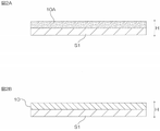
- FIG. 1 is a schematic cross-sectional view of one embodiment of the joining sheet of the present invention.
- 2A and 2B show some steps in one embodiment of the method for producing a joined sheet of the present invention.
- FIG. 2A represents the coating film forming process
- FIG. 2B represents the drying process.
- 3A to 3C are process diagrams of an example of a solder bonding method using the bonding sheet shown in FIG. 3A represents the preparation process
- FIG. 3B represents the lamination process
- FIG. 3C represents the heating process.
- FIG. 4 is a scanning electron microscope (SEM) image processing diagram of a cross section of the bonded sheet of Example 1.
- FIG. 5 is a scanning electron microscope (SEM) image processing diagram of the cross section of the joint sheet of Comparative Example 1.
- FIG. 6 is an energy dispersive X-ray analysis (EDX) image processing diagram of the cross section of the joining sheet of Example 1.
- FIG. 7A to 7C are scanning electron microscope (SEM) image processing diagrams of cross sections of the joint sheets of Example 1 and Comparative Example 2 for evaluating uneven distribution of flux.
- 7A and 7B are scanning electron microscope (SEM) image processing views of the cross section of the bonded sheet of Example 1.
- FIG. 7C is a scanning electron microscope (SEM) image processing diagram of the cross section of the joint sheet of Comparative Example 2.
- FIG. 1 is a schematic cross-sectional view of a joining sheet 10 as one embodiment of the joining sheet of the present invention (illustrating a state in which the joining sheet 10 is sandwiched between base materials S1 and S2).
- the joining sheet 10 is used for soldering two objects to be joined.
- the joining sheet 10 has a sheet shape with a predetermined thickness and extends in a direction perpendicular to the thickness direction H (plane direction).
- the joining sheet 10 may have a long sheet shape. When the joining sheet 10 has a long sheet shape, it may have the form of a wound roll. Alternatively, the joining sheet 10 may have a sheet form.
- the thickness of the joining sheet is, for example, 30 ⁇ m or less, preferably 25 ⁇ m or less, more preferably 20 ⁇ m or less, and even more preferably 15 ⁇ m or less.
- the thickness of the joining sheet is, for example, 3 ⁇ m or more, preferably 5 ⁇ m or more, from the viewpoint of handling properties of the joining sheet.
- the joining sheet contains matrix resin, solder particles, and fluxing agent.
- the matrix resin contains a thermosetting resin and a thermoplastic resin.
- the thermosetting resin is preferably liquid at room temperature (25°C)
- the thermoplastic resin is solid at room temperature (25°C).
- thermosetting resins examples include epoxy resins, urea resins, melamine resins, diallyl phthalate resins, silicone resins, phenol resins, thermosetting acrylic resins, thermosetting polyesters, thermosetting polyimides, and thermosetting polyurethanes. be done. Epoxy resins and thermosetting polyurethanes are preferred, and epoxy resins are more preferred.
- Epoxy resins include, for example, aromatic epoxy resins, nitrogen-containing ring epoxy resins, aliphatic epoxy resins, alicyclic epoxy resins, glycidyl ether type epoxy resins, and glycidyl amine type epoxy resins.
- aromatic epoxy resins include bisphenol-type epoxy resins, novolac-type epoxy resins, fluorene-type epoxy resins, and triphenylmethane-type epoxy resins.
- bisphenol-type epoxy resins include bisphenol A-type epoxy resin, bisphenol F-type epoxy resin, bisphenol S-type epoxy resin, hydrogenated bisphenol A-type epoxy resin, and dimer acid-modified bisphenol-type epoxy resin.
- novolak-type epoxy resins examples include phenol novolac-type epoxy resins, cresol novolak-type epoxy resins, and biphenyl-type epoxy resins.
- fluorene-type epoxy resins examples include bisarylfluorene-type epoxy resins.
- triphenylmethane-type epoxy resins examples include trishydroxyphenylmethane-type epoxy resins.
- Nitrogen-containing ring epoxy resins include, for example, triepoxypropyl isocyanurate (triglycidyl isocyanurate) and hydantoin epoxy resins.
- Alicyclic epoxy resins include, for example, dicyclocyclic epoxy resins.
- epoxy resins can be used. Specifically, jER (registered trademark) 828 (bisphenol A type epoxy resin, manufactured by Mitsubishi Chemical Corporation) is used.
- the epoxy equivalent of the epoxy resin is, for example, 80 g/eq or more, preferably 100 g/eq or more, more preferably 150 g/eq or more, and for example, 500 g/eq or less, preferably 400 g/eq. or less, more preferably 250 g/eq or less.
- the epoxy resin preferably a bisphenol type epoxy resin that is liquid at room temperature (25°C), more preferably a bisphenol A type epoxy resin that is liquid at room temperature (25°C) is used.
- the curing temperature of the thermosetting resin is, for example, 90°C or higher, preferably 140°C or higher, and is, for example, 250°C or lower, preferably 230°C or lower, and more preferably 200°C. or less, more preferably 160° C. or less.
- thermosetting resin is preferably liquid at room temperature (25°C). Adhesion reliability increases if the thermosetting resin is liquid at room temperature.
- liquid refers to a liquid or fluid having a viscosity of 200 Pa ⁇ s or less at room temperature (25°C).
- thermosetting resins can be used alone or in combination of two or more.
- the proportion of the thermosetting resin in the matrix resin is, for example, 50% by mass or more, preferably 60% by mass or more, and 90% by mass or less, preferably 80% by mass or less. Further, the proportion of the thermosetting resin in the joining sheet is, for example, 10% by mass or more, preferably 20% by mass or more, and 50% by mass or less, preferably 30% by mass or less. If the proportion of the thermosetting resin is less than the above lower limit, a sufficient reinforcing effect may not be obtained after soldering. On the other hand, if this ratio exceeds the above upper limit, it may be difficult to form a sheet.
- the matrix resin may further contain a phenol resin as a curing agent for the epoxy resin.
- phenolic resins include, for example, novolak-type phenolic resins and resol-type phenolic resins.
- Novolac-type phenolic resins include, for example, phenol novolak resins, phenol aralkyl resins, cresol novolac resins, tert-butylphenol novolak resins, and nonylphenol novolak resins.
- thermoplastic resins include polyolefins (eg, polyethylene, polypropylene and ethylene-propylene copolymers), acrylic resins, phenoxy resins, polyesters, polyvinyl acetates, ethylene-vinyl acetate copolymers, polyvinyl chloride, polystyrene, Polyacrylonitrile, polyamide (nylon (registered trademark)), polycarbonate, polyacetal, polyethylene terephthalate, polyphenylene oxide, polyphenylene sulfide, polysulfone, polyethersulfone, polyetheretherketone, polyarylsulfone, thermoplastic polyimide, thermoplastic polyurethane, polyaminobis Maleimide, polyamideimide, polyetherimide, bismaleimide triazine resin, polymethylpentene, fluorinated resin, liquid crystal polymer, olefin-vinyl alcohol copolymer, ionomer, polyarylate, acrylonitrile-ethylene-ethylene
- the thermoplastic resin preferably includes acrylic resin and polyester, more preferably acrylic resin.
- Acrylic resins consist of acrylic polymers, such acrylic polymers are, for example, methyl (meth)acrylate, ethyl (meth)acrylate, propyl (meth)acrylate, butyl (meth)acrylate, (meth)acrylic Monomer containing alkyl (meth)acrylate ester having an alkyl moiety having 1 to 12 carbon atoms such as hexyl acid, octyl (meth)acrylate, decyl (meth)acrylate, and dodecyl (meth)acrylate as a main component. It is a polymer.
- “(Meth)acrylic acid” means acrylic acid and/or methacrylic acid. Monomers can be used alone or in combination.
- the monomer may contain one or more copolymerizable monomers copolymerizable with the (meth)acrylic acid alkyl ester.
- Copolymerizable monomers include functional group-containing vinyl monomers and aromatic vinyl monomers.
- the copolymerizable monomer helps modify the acrylic polymer, such as ensuring cohesive strength of the acrylic polymer.
- Examples of functional group-containing vinyl monomers include carboxy group-containing vinyl monomers, acid anhydride vinyl monomers, hydroxyl group-containing vinyl monomers, sulfo group-containing vinyl monomers, phosphoric acid group-containing vinyl monomers, cyano group-containing vinyl monomers, and glycidyl group-containing vinyl monomers.
- Vinyl monomers are mentioned.
- a hydroxyl group-containing vinyl monomer is used.
- Aromatic vinyl monomers include, for example, styrene, chlorostyrene, chloromethylstyrene, and ⁇ -methylstyrene.
- acrylic polymer Commercially available products can be used as the acrylic polymer. Specifically, UH-2170 (manufactured by Toagosei Co., Ltd.) can be mentioned as a hydroxyl group-containing styrene acrylic polymer.
- the glass transition temperature Tg of the acrylic resin is, for example, -100°C or higher, preferably -50°C or higher, and is, for example, 100°C or lower, preferably 50°C or lower.
- the glass transition temperature (Tg) of acrylic resin is obtained based on the Fox formula.
- the softening temperature of the thermoplastic resin is, for example, 40° C. or higher, preferably 45° C. or higher, more preferably 50° C. or higher, and most preferably 55° C. or higher.
- °C or lower preferably 120 °C or lower, more preferably 100 °C or lower, most preferably 80 °C or lower.
- the weight average molecular weight (Mw) of the thermoplastic resin is, for example, 8,000 or more, preferably 10,000 or more, and is, for example, 2 million or less, preferably 1,500,000 or less.
- the weight average molecular weight (standard polystyrene conversion value) of the acrylic resin is calculated by GPC. When the weight-average molecular weight (Mw) is within the above range, it is possible to suppress the formation of pinholes when forming into a sheet.
- thermoplastic resin is preferably solid (solid) at room temperature (25°C). If the thermoplastic resin is solid at room temperature, it is possible to ensure shape retention and maintain the sheet shape of the joined sheet.
- thermoplastic resins can be used singly or in combination of two or more.
- the proportion of the thermoplastic resin in the matrix resin is, for example, 10% by mass or more, preferably 20% by mass or more, and 50% by mass or less, preferably 40% by mass or less. Further, the proportion of the thermoplastic resin in the joining sheet is preferably 2% by mass or more, more preferably 5% by mass or more, still more preferably 10% by mass or more, and is preferably 50% by mass or less, more preferably 30% by mass. % by mass or less, more preferably 20% by mass or less. Within the above range, both the moldability of the bonding sheet and the bonding strength of the bonding sheet to the bonding target can be achieved.
- thermosetting resin In the matrix resin, the thermosetting resin and the thermoplastic resin are compatible with each other.
- solder material that forms the solder particles is, for example, solder metal.
- Solder metals include solder materials that do not contain lead (lead-free solder) from the viewpoint of environmental suitability.
- solder materials include, for example, tin-bismuth based alloys and tin-silver based alloys.
- Tin-bismuth alloys include, for example, tin-bismuth alloys (Sn-Bi) and tin-bismuth-indium alloys (Sn-Bi-In).
- Tin-silver alloys include, for example, tin-silver alloys (Sn-Ag) and tin-silver-copper alloys (Sn-Ag-Cu). From the standpoint of low temperature bonding, the solder material preferably includes tin-bismuth alloys and tin-bismuth-indium alloys.
- the content of tin in the tin-bismuth alloy is, for example, 20% by mass or more, preferably 30% by mass or more, and is, for example, 50% by mass or less, preferably 45% by mass or less.
- the content of bismuth in the tin-bismuth alloy is, for example, 50% by mass or more, preferably 55% by mass or more, and, for example, 80% by mass or less, preferably 70% by mass or less. .
- the melting point of the solder particles is, for example, 100° C. or higher, preferably 130° C. or higher, and is, for example, 240° C. or lower, preferably 200° C. or lower, more preferably 160° C. or lower. and more preferably 150° C. or less.
- the melting point of the solder material can be determined by differential scanning calorimetry (DSC) (hereinafter, the same applies to flux agents). If the melting point of the solder particles is within the above range, it is possible to suppress the melting of the solder in the heating process during sheet formation. In addition, it is possible to suppress the influence of heat applied to the periphery of the mounting portion during mounting by soldering.
- the shape of the solder particles includes, for example, a spherical shape, a plate shape, and a needle shape, preferably a spherical shape.
- the median diameter (particle diameter) D50 of the solder particles is, for example, 10 nm or more, preferably 1 ⁇ m or more.
- the particle diameter D50 of the solder particles is, for example, 10 ⁇ m or less, preferably 8 ⁇ m or less, more preferably 6 ⁇ m or less, even more preferably 5 ⁇ m or less, particularly preferably 4 ⁇ m or less.
- the particle diameter D50 is equal to or less than the above upper limit, the dispersibility of the solder particles in the joining sheet can be improved. In addition, it is possible to reduce the thickness of the joining sheet.
- the particle diameter D50 of the solder particles is the median diameter in the volume-based particle size distribution (particle size at which the volume cumulative frequency reaches 50% from the small diameter side), for example, based on the particle size distribution obtained by the laser diffraction/scattering method (The same applies to fluxing agents below).
- the surface of the solder particles is generally covered with an oxide film made of oxide of the solder material.
- the thickness of the oxide film is, for example, 1 to 20 nm.
- the oxygen concentration of the solder particles can be measured by a known method, for example, by a nitrogen/oxygen simultaneous analyzer (EMGA-650, manufactured by Horiba, Ltd.).
- the oxygen concentration of the solder particles is preferably low.
- the oxygen concentration of the solder particles is, for example, 100 ppm or more, preferably 350 ppm or more, more preferably 550 ppm or more, more preferably 700 ppm or more, and for example, 3000 ppm or less, preferably 2500 ppm or less. , more preferably 2000 ppm or less, still more preferably 1400 ppm or less.
- the oxygen concentration of the solder particles is within the above range, the solder particles can be efficiently accumulated.
- solder particles can be used singly or in combination of two or more.
- the content of the solder particles in the joining sheet is, for example, 50 parts by mass or more, preferably 100 parts by mass or more, more preferably 120 parts by mass or more with respect to 100 parts by mass of the matrix resin.
- the proportion of solder particles in the bonding sheet is, for example, 5% by mass or more, preferably 10% by mass or more, more preferably 20% by mass or more, still more preferably 30% by mass or more, particularly preferably 40% by mass or more, and most preferably 40% by mass or more. Preferably, it is 50% by mass or more.
- the content of the solder particles is at least the above lower limit, cohesiveness of the solder particles in the soldering process can be ensured.
- the content of the solder particles in the joining sheet is, for example, 600 parts by mass or less, preferably 450 parts by mass or less, more preferably 170 parts by mass or less with respect to 100 parts by mass of the matrix resin.
- the proportion of solder particles in the joining sheet is, for example, 80% by mass or less, preferably 70% by mass or less, and more preferably 60% by mass or less. When the content of the solder particles is equal to or less than the above upper limit, the formability of the joining sheet is excellent.
- the solder particles are evenly dispersed in the matrix resin. That is, the solder particles are distributed uniformly in the matrix resin.
- the "uniform concentration" has a distribution width of ⁇ 20%, preferably ⁇ 10%, with respect to the standard concentration based on the content of the solder particles in the matrix resin.
- the concentration distribution can be observed, for example, with a scanning electron microscope (SEM).
- the flux agent removes (activates) the oxide film on the surface of the solder particles when the solder particles are melted by heating.
- Examples of fluxing agents include organic acids, quinolinol derivatives, and metal carbonyl salts.
- Organic acids include, for example, carboxylic acids.
- Carboxylic acids include monocarboxylic acids, dicarboxylic acids, and tricarboxylic acids.
- Monocarboxylic acids include, for example, glycolic acid, lactic acid, and 2-hydroxybutanoic acid.
- Dicarboxylic acids include, for example, tartaric acid, malic acid, adipic acid, malonic acid, succinic acid, glutaric acid, pimelic acid, suberic acid, and sebacic acid.
- Tricarboxylic acids include, for example, citric acid.
- the fluxing agent is preferably carboxylic acid, more preferably dicarboxylic acid, and still more preferably malic acid and malonic acid.
- the fluxing agent is preferably solid at 25°C.
- the melting point of the fluxing agent is higher than 25°C, preferably 80°C or higher, more preferably 100°C or higher, and even more preferably 120°C or higher.
- the melting point of the fluxing agent is, for example, 200° C. or lower, preferably 180° C. or lower, more preferably 160° C. or lower.
- the fluxing agent is preferably a carboxylic acid that is solid at 25°C.
- the shape of the flux agent is not particularly limited, and examples thereof include a plate shape, a needle shape, and a spherical shape.
- the particle diameter D50 of the fluxing agent is, for example, 2 ⁇ m or more, preferably 3 ⁇ m or more, and is, for example, 20 ⁇ m or less, preferably 10 ⁇ m or less, and more preferably 6 ⁇ m or less. If the particle diameter D50 of the fluxing agent is within the above range, the dispersibility of the fluxing agent can be improved.
- These flux agents can be used alone or in combination of two or more.
- the content of the fluxing agent in the bonding sheet is, for example, 1 part by mass or more, preferably 5 parts by mass or more, more preferably 7.5 parts by mass or more, and still more preferably 10 parts by mass or more with respect to 100 parts by mass of the matrix resin. is. Also, the proportion of the fluxing agent in the joining sheet 10 is, for example, 1% by mass or more, preferably 2% by mass or more, and more preferably 3% by mass or more. When the content of the fluxing agent is at least the above lower limit, cohesiveness of the solder particles can be ensured during the soldering process.
- the content of the fluxing agent in the joining sheet is, for example, 50 parts by mass or less, preferably 20 parts by mass or less, more preferably 17.5 parts by mass or less, and even more preferably 15 parts by mass with respect to 100 parts by mass of the matrix resin. parts, particularly preferably 12.5 parts by mass or less, most preferably 10 parts by mass or less.
- the proportion of the fluxing agent in the joining sheet is, for example, 50% by mass or less, preferably 20% by mass or less, more preferably 10% by mass or less, even more preferably 8% by mass or less, particularly preferably 7% by mass or less, and most preferably. is 5% by mass or less. When the content of the fluxing agent is equal to or less than the above upper limit, the formability of the bonded sheet is excellent.
- the bonding sheet preferably satisfies the following formula (1), where x 1 ppm is the oxygen concentration of the solder particles, and y 1 mmol is the content of the fluxing agent with respect to 100 parts by weight of the solder particles. 0.045 ⁇ y1/ x1 ⁇ 0.090 ( 1 )
- y 1 /x 1 is, for example, 0.045 or more, preferably 0.050 or more, and, for example, 0.099 or less, preferably 0.090 or less, more preferably is less than or equal to 0.080.
- y 1 /x 1 is within the above range, solder particles are likely to accumulate, and surplus acid is small, so it is possible to suppress an increase in resistance value due to corrosion of the solder portion after connection.
- the bonding sheet preferably satisfies the following formula (2), where x 2 ⁇ m is the median diameter (D 50 ) of the solder particles, and y 2 mol is the content of the fluxing agent with respect to 100 parts by weight of the solder particles. . 0.150 ⁇ x2y2 ⁇ 0.300 ( 2 )
- x 2 y 2 is, for example, 0.150 or more, preferably 0.155 or more, more preferably 0.157 or more, and for example, 0.314 or less, preferably , is 0.300 or less, more preferably 0.270 or less.
- x 2 y 2 is within the above range, solder particles are likely to accumulate, and surplus acid is small, so it is possible to suppress an increase in resistance value caused by corrosion of the solder portion after connection.
- the flux agent is unevenly distributed around the solder particles in the matrix resin. That is, the flux agent is distributed in the matrix resin such that the concentration around the solder particles is higher than the concentration around the solder particles.
- “surrounding the solder particles” specifically refers to a range of twice, preferably 1.5 times the diameter of the solder particles, and "the concentration around the solder particles is higher than the concentration other than the solder particles”.
- “Also high” means that the surrounding maximum density is twice, preferably five times the minimum density other than the surroundings. The concentration distribution can be confirmed, for example, with a scanning electron microscope (SEM).
- the flux agent is unevenly distributed around the solder particles in this way, the oxide film on the surface of the solder particles can be efficiently removed, and the solder particles can be agglomerated. Moreover, since the flux agent is unevenly distributed around the solder particles, excess flux agent other than around the solder particles can be reduced, and an increase in the resistance value of the solder portion can be suppressed.
- the fluxing agent unevenly distributed around the solder particles preferably contains a metal derived from the solder particles.
- the metal derived from the solder particles corresponds to the type of solder particles (solder metal) contained.
- solder metal solder metal
- Methods for measuring metals derived from solder particles include, for example, energy dispersive X-ray spectroscopy (EDX).
- the content of the solder particles in the flux agent is, for example, 50 parts by mass or more, preferably 100 parts by mass or more, and for example, 500 parts by mass or less with respect to 100 parts by mass of the matrix resin, Preferably, it is 300 parts by mass or less. If the content of the solder particles is within the above range, the oxide film of the solder particles can be efficiently removed, and the solder particles can be accumulated without forming bridges on the electrodes.
- the bonding sheet of the present invention may optionally include, for example, a curing agent and/or curing accelerator for thermosetting resins, and silane coupling from the viewpoint of improving the adhesion strength between solder particles and thermoplastic resins.
- Additives such as agents can be contained in appropriate proportions.
- the joining sheet can be manufactured by the following manufacturing method.
- This manufacturing method is an embodiment of the bonded sheet manufacturing method of the present invention.
- the first solvent is a solvent capable of dissolving the fluxing agent, and is selected according to the type of fluxing agent.
- the first solvent is not limited as long as it dissolves the fluxing agent.
- First solvents include, for example, water, alcohols, carboxylic acids, and ketones.
- Alcohols include, for example, methanol, ethanol, isopropyl alcohol, and butanol.
- Carboxylic acids include formic acid and acetic acid.
- Ketones include, for example, acetone, methyl ethyl ketone and methyl isobutyl ketone.
- the first solvent is preferably an alcohol or a ketone, more preferably acetone.
- the fluxing agent concentration (non-volatile component concentration) of the fluxing agent solution is, for example, 10% by mass or more, preferably 20% by mass or more, more preferably 25% by mass, from the viewpoint of miscibility with other components in the following second step. % or more, and for example, 50% by mass or less, preferably 40% by mass or less, more preferably 35% by mass or less.
- the second solvent is preferably a solvent in which at least part of the fluxing agent dissolves.
- Second solvents include, for example, ketones, alkyl esters, aliphatic hydrocarbons, and aromatic hydrocarbons. Ketones are preferred. Ketones include, for example, acetone, methyl ethyl ketone, methyl isobutyl ketone, and cyclohexanone.
- Alkyl esters include, for example, methyl acetate, ethyl acetate, butyl acetate, isobutyl acetate, and amyl acetate.
- Aliphatic hydrocarbons include, for example, n-hexane, n-heptane, octane, cyclohexane, and methylcyclohexane.
- Aromatic hydrocarbons include, for example, toluene, xylene, and ethylbenzene.
- the second solvent may be used alone, or two or more of them may be used in combination.
- the second solvent may be of the same type as the first solvent, or may be of a different type.
- the solid content concentration of the mixed composition is, for example, 50% by mass or more, preferably 60% by mass or more, more preferably 65% by mass or more, from the viewpoint of ease of forming a coating film in the following third step. Also, for example, it is 90% by mass or less, preferably 80% by mass or less, more preferably 75% by mass or less.
- the mixed composition is applied onto the substrate S1 to form a coating film 10A, and then, as shown in FIG. 2B, the coating film 10A is dried to form the joining sheet 10.
- the substrate S1 include a plastic film.
- the plastic film include polyethylene terephthalate film, polyethylene film, polypropylene film, and polyester film.
- the surface of the base material is preferably surface release treated.
- the joining sheet 10 is dried by heating.
- the drying temperature is equal to or higher than the softening temperature of the thermoplastic resin, lower than the melting points of the solder particles and the fluxing agent, and lower than the curing temperature of the thermosetting resin.
- the drying temperature is preferably 60° C. or higher, more preferably 75° C. or higher, and preferably 130° C. or lower, more preferably 120° C. or lower.
- the base material S2 may be laminated on the joining sheet 10 on the base material S1.
- the plastic film described above for the substrate S1 can be used (FIG. 1 illustrates a state in which the joining sheet 10 is sandwiched between the substrates S1 and S2).
- the joining sheet 10 can be manufactured as described above.
- the flux agent is dissolved in the first solvent in the first step.
- the fluxing agent is dissolved in the first solvent and mixed with other components (matrix resin component, solder particles). Therefore, in the coating film formed in the third step, the flux agent is unevenly distributed around the solder particles in the matrix resin. As a result, the oxide film on the surface of the solder particles can be efficiently removed and the solder particles can be agglomerated.
- the flux agent is unevenly distributed around the solder particles, it is possible to reduce the amount of excess flux agent other than around the solder particles, thereby suppressing an increase in the resistance value of the solder portion.
- FIG. 3 shows an example of a solder joint method using the joint sheet 10.
- a printed circuit board 30, an electronic component 40, and a joining sheet 10 are prepared (preparation step).
- the wired circuit board 30 is an example of one bonding object, and has a substrate 31 and a plurality of terminals 32 .
- the substrate 31 is, for example, an insulating substrate having a flat plate shape.
- the terminal 32 is made of metal.
- the multiple terminals 32 are separated from each other.
- the maximum length of the terminal 32 is, for example, 10 ⁇ m or more and, for example, 200 ⁇ m or less.
- the interval between terminals 32 is, for example, 10 ⁇ m or more and, for example, 200 ⁇ m or less.
- the electronic component 40 is an example of the other object to be joined, and has a body portion 41 and a plurality of terminals 42 .
- the terminal 42 is made of metal.
- the plurality of terminals 42 are separated from each other.
- the plurality of terminals 42 are arranged and sized to face the plurality of terminals 32 of the printed circuit board 30 .
- solder particles 11 and matrix resin 12 are illustrated.
- the wired circuit board 30, the joining sheet 10, and the electronic component 40 are laminated in this order (lamination step). Specifically, the wiring circuit board 30 and the electronic component 40 are arranged so that the corresponding terminals 32 , 42 face each other, and the bonding sheet 10 is placed so that the terminals 32 , 42 are embedded in the bonding sheet 10 . crimp through. Thereby, the laminated body W is obtained. The printed circuit board 30 and the electronic component 40 are temporarily joined via the joining sheet 10 .
- the heating temperature is a temperature above the melting point of the solder particles 11 and the flux agent, a temperature above the softening point of the thermoplastic resin, and a temperature above the curing temperature of the thermosetting resin.
- the heating temperature is appropriately determined depending on the type of thermosetting resin, thermoplastic resin, solder particles and fluxing agent, and is, for example, 120°C or higher, preferably 130°C or higher, or, for example, 170°C. or less, preferably 160° C. or less.
- the heating time is, for example, 3 seconds or more, and is, for example, 60 seconds or less, preferably 30 seconds or less.
- thermoplastic resin is once melted in the joining sheet 10, and the flux agent is melted to exhibit the function of removing the oxide film on the surface of the solder particles.
- the solder particles are melted, agglomerated, gathered between the terminals 32 and 42 and agglomerated (self-alignment).
- Curing of the thermosetting resin proceeds around the condensed solder material.
- the solder material that has aggregated between the terminals 32 and 42 solidifies to form the solder portion 11A.
- the printed circuit board 30 and the electronic component 40 are joined by the joining sheet 10, and the terminals 32 and 42 are electrically connected by the solder portion 11A.
- a cured resin portion 12A derived from the matrix resin 12 is formed around the solder portion 11A.
- the cured resin portion 12A contains at least partially cured thermosetting resin and solidified thermoplastic resin, and preferably contains the completely cured thermosetting resin and the solidified thermoplastic resin. .
- the electronic component 40 can be mounted on the wired circuit board 30 using the joining sheet 10 .
- the flux agent is evenly dispersed throughout the matrix resin (thermoplastic resin and thermosetting resin) as well as around the solder particles.
- the bonding sheet flux agents other than the flux agent that exists around the solder particles and contributes to the removal of the oxide film of the solder particles do not exist around the solder particles and do not contribute to the removal of the oxide film of the solder particles. Excess fluxing agent is present. In this case, since the solder particles dispersed throughout the matrix resin need to reach the surface of the solder particles, the required amount of the flux agent is become more. As a result, there is a problem that the resistance value increases due to metal corrosion of the solder portion due to the excessive flux agent.
- the flux agent 13 is unevenly distributed around the solder particles 11 in the matrix resin 12, as shown in the enlarged view of FIG. Therefore, the amount of excess flux other than the flux necessary for efficiently removing the oxide film on the surface of the solder particles can be reduced. As a result, it is possible to suppress an increase in the resistance value of the solder portion due to excess flux. As a result, durability can be improved.
- the flux agent is dissolved in the first solvent in the first step. Therefore, as the joining sheet 10 dries, the flux agent is unevenly distributed around the solder particles in the matrix resin. As a result, the total amount of required fluxing agent can be suppressed, and an increase in the resistance value of the solder portion can be suppressed.
- the bonding sheet 10 is arranged between the electronic component 40 and the wired circuit board 30.
- the joining sheet 10 is laminated on one of the wired circuit boards 30 so that the terminals 32 of the wired circuit board 30 are in contact with each other, and then the electronic component 40 is placed on the joining sheet 10. It is also possible to laminate such that the terminals 42 are in contact with the joining sheet 10 . In other words, the joining sheet 10 and the electronic component 40 can be sequentially laminated on the wiring circuit board 30 on one side.
- the electronic component is manufactured by bonding the electronic component 40 and the wired circuit board 30 with the bonding sheet 10.
- the wired circuit board 30 and another wired circuit board may be bonded with the bonding sheet 10. It is also possible to manufacture electronic components.
- Example 1 A bonded sheet of Example 1 was produced as follows.
- an epoxy resin (trade name “jER828”, bisphenol A type epoxy resin, epoxy equivalent 184 to 194 g / eq, liquid at room temperature (25 ° C.), manufactured by Mitsubishi Chemical Corporation) as a thermosetting resin 60 parts by mass
- Acrylic resin (trade name “ARUFON UH-2170”, hydroxyl group-containing styrene acrylic polymer, solid at room temperature (25 ° C.), manufactured by Toagosei Co., Ltd.) as a thermoplastic resin 40 parts by mass
- solder particles 42 mass% Sn-58 mass% Bi alloy, melting point 139°C, spherical shape, particle size D50 is 3 ⁇ m, oxygen concentration 1100 ppm) and 150 parts by mass of fluxing agent solution were added to methyl ethyl ketone (MEK) and mixed to obtain a solid content concentration of 72 mass%. was prepared (second step).
- the content of the fluxing agent in this mixed composition was 10 parts by mass.
- composition of the joining sheet of Example 1 is shown in Table 1 (compositions of joining sheets of Examples and Comparative Examples below are also shown in Tables 1 and 2).
- Tables 1 and 2 the unit of each numerical value representing the composition of the composition is relative "parts by weight”.
- Example 2 In the second step, the amount of the fluxing agent (malic acid) in the mixed composition was changed from 10 parts by mass to 17.5 parts by mass to prepare a mixed composition with a solid content concentration of 63% by mass (second step ), a bonded sheet was produced in the same manner as the bonded sheet of Example 1, except for the above.
- the fluxing agent malic acid
- Example 3 In the second step, the amount of the fluxing agent (malic acid) in the mixed composition was changed from 10 parts by mass to 20 parts by mass to prepare a mixed composition with a solid content concentration of 61% by mass (second step).
- a bonded sheet of Example 3 was produced in the same manner as the bonded sheet of Example 1 except for the above.
- Example 4 In the first step, instead of malic acid as a fluxing agent, malonic acid (particle size D50 : 4.5 ⁇ m, melting point: 135° C., solid at room temperature (25° C.)) is used, and in the second step, mixing Instead of 10 parts by mass of the fluxing agent (malonic acid) in the composition, 10 parts by mass of the fluxing agent (malonic acid) was used to prepare a mixed composition having a solid content concentration of 72% by mass (second step). A bonded sheet of Example 4 was produced in the same manner as the bonded sheet of Example 1.
- Example 5 In the first step, malonic acid is used instead of malic acid as a fluxing agent, and in the second step, 10 parts by mass of the fluxing agent (malonic acid) in the mixed composition is replaced with a fluxing agent (malonic acid).
- a bonding sheet of Example 5 was produced in the same manner as the bonding sheet of Example 1, except that a mixed composition having a solid content concentration of 61% by mass was prepared (second step).
- Example 6 In the second step, as the solder particles in the mixed composition, solder particles (42% by mass Sn-58% by mass Bi alloy, melting point 139 ° C., spherical shape, particle diameter D 50 is 5 ⁇ m, oxygen concentration 650 ppm), A joining sheet of Example 6 was produced in the same manner as the joining sheet of Example 1, except that a mixed composition having a solid content concentration of 72% by mass was prepared (second step).
- Example 7 In the second step, instead of 10 parts by mass of the fluxing agent (malic acid) in the mixed composition, 17.5 parts by mass of the fluxing agent (malic acid) is used, and solder particles (42 parts by mass) are used as the solder particles in the mixed composition. % Sn-58% by mass Bi alloy, melting point 139° C., spherical shape, particle size D50 3 ⁇ m, oxygen concentration 1500 ppm), and a mixed composition with a solid content concentration of 61% by mass was prepared (second step). A bonded sheet of Example 7 was produced in the same manner as the bonded sheet of Example 1 except for the above.
- Example 8 In the second step, instead of 10 parts by mass of the fluxing agent (malic acid) in the mixed composition, 20 parts by mass of the fluxing agent (malic acid) is used, and the solder particles in the mixed composition are solder particles (42% by mass of Sn ⁇ 58% by mass Bi alloy, melting point 139° C., spherical shape, particle size D50 3 ⁇ m, oxygen concentration 1500 ppm), and a mixed composition with a solid content concentration of 61% by mass was prepared (second step) A bonded sheet of Example 8 was prepared in the same manner as the bonded sheet of Example 1.
- solder particles 42 mass% Sn-58 mass% Bi alloy, melting point 139 ° C., spherical shape, particle diameter D50 is 3 ⁇ m, oxygen concentration 300 ppm
- a joining sheet of Example 9 was produced in the same manner as the joining sheet of Example 1, except that a mixed composition having a solid content concentration of 61% by mass was prepared (second step).
- solder particles (42% by mass Sn-58% by mass Bi alloy, melting point 139° C., spherical shape, particle diameter D 50 is 7 ⁇ m, oxygen concentration 500 ppm) are used as the solder particles in the mixed composition
- a joining sheet of Example 10 was produced in the same manner as the joining sheet of Example 1, except that a mixed composition having a solid content concentration of 72% by mass was prepared (second step).
- Epoxy resin (trade name “jER828”, bisphenol A type epoxy resin, epoxy equivalent 184 to 194 g / eq, liquid at room temperature (25 ° C.), manufactured by Mitsubishi Chemical Corporation) as a thermosetting resin, 60 parts by mass, and a thermoplastic resin 40 parts by mass of acrylic resin (trade name “ARUFON UH-2170”, hydroxyl group-containing styrene acrylic polymer, solid at room temperature (25 ° C.), manufactured by Toagosei Co., Ltd.) and solder particles (42 mass% Sn-58 mass% Bi 150 parts by mass of alloy, melting point 139°C, spherical shape, particle diameter D50 is 3 ⁇ m, oxygen concentration 1100 ppm) and 50 parts by mass of fluxing agent (malic acid) were added to methyl ethyl ketone (MEK) and mixed to obtain a solid content concentration of A 70 wt% mixed composition was prepared.
- epoxy resin trade name “jER828”, bisphenol A type epoxy resin,
- the coating film was dried (third step).
- the drying temperature was 80° C. and the drying time was 5 minutes. As a result, a bonding sheet having a thickness of 10 ⁇ m was formed on the substrate (release liner).
- Sample cross-sections were prepared as follows. Using an FIB-SEM apparatus (“Helios G4 UX”, manufactured by Thermo Fisher Scientific), the cross section of the sample was adjusted by irradiating a Ga ion beam under conditions of an acceleration voltage of 30 kV and a temperature of ⁇ 160° C. A backscattered electron image of the cross-section of the bonded sheet prepared as described above was obtained using an FIB-SEM device (“Helios G4 UX”, manufactured by Thermo Fisher Scientific) under the conditions of an acceleration voltage of 2 kV and a temperature of ⁇ 160° C. Obtained.
- FIB-SEM apparatus Helios G4 UX
- FIG. 1 A scanning electron microscope (SEM) image processing diagram of Example 1 is shown in FIG.
- solder particles 11 were dispersed in the matrix resin 12, and the flux agent 13 was unevenly distributed around the solder particles 11 in the matrix resin 12.
- the solder particles 11 are dispersed in the matrix resin 12, but the flux agent 13 is not unevenly distributed around the solder particles 11 in the matrix resin 12.
- the middle upper diagram in FIG. 6 shows a scanning electron microscope (SEM) image processing diagram of the cross section of the bonding sheet of Example 1.
- the diagram on the upper right side of FIG. 6 is an energy dispersive X-ray analysis (EDX) image processing diagram showing the presence or absence of inclusion of metals (Bi, Sn) derived from the solder particles 11 in the matrix resin 12 portion. As shown in the upper right diagram of FIG. 6, metals (Bi, Sn) derived from the solder particles 11 were not detected in the matrix resin 12 portion.
- EDX energy dispersive X-ray analysis
- the diagram on the lower right side of FIG. 6 is an image processing diagram of energy dispersive X-ray analysis (EDX) showing the presence or absence of metal (Bi, Sn) contained in the solder particles 11 in the solder particles 11 portion. As shown in the lower right diagram of FIG. 6 , Sn, which is the metal of the solder particles 11 , was detected in the Sn-rich phase of the solder particles 11 .
- EDX energy dispersive X-ray analysis
- the lower center diagram of FIG. 6 is an image processing diagram of energy dispersive X-ray analysis (EDX) showing the presence or absence of metal (Bi, Sn) contained in the solder particles 11 in the solder particles 11 portion. As shown in the lower center diagram of FIG. 6 , Bi, which is the metal of the solder particles 11 , was detected in the Bi-rich phase of the solder particles 11 .
- EDX energy dispersive X-ray analysis
- the lower left diagram of FIG. 6 is an energy dispersive X-ray analysis (EDX) image processing diagram showing the presence or absence of inclusion of metals (Bi, Sn) derived from the solder particles 11 in the flux agent 13 portion. As shown in the lower left diagram of FIG. 6, metals (Bi, Sn) derived from the solder particles 11 were detected in the flux agent 13 portion.
- EDX energy dispersive X-ray analysis
- the upper left diagram of FIG. 6 is an energy dispersive X-ray analysis (EDX) image processing diagram showing the presence or absence of inclusion of metals (Bi, Sn) derived from the solder particles 11 in the flux agent 13 portion. As shown in the upper left diagram of FIG. 6, metals (Bi, Sn) derived from the solder particles 11 were detected in the flux agent 13 portion.
- EDX energy dispersive X-ray analysis
- Each bonding sheet was evaluated for the accumulation of solder particles by heating.
- a sample was prepared by bonding two printed circuit boards together via a bonding sheet.
- Each wired circuit board has a transparent glass substrate and a plurality of terminals (30 ⁇ m wide) formed thereon. A plurality of terminals are arranged in parallel on one surface of the glass substrate (the space between adjacent terminals is 30 ⁇ m).
- two printed circuit boards are joined via a joining sheet so that the terminals of one printed circuit board face the terminals of the other printed circuit board.
- the samples were then heat treated at 160°C for 30 seconds.
- Each bonded sheet was evaluated for durability by resistance value measurement as follows. First, two printed circuit boards were bonded together via a bonding sheet to prepare a sample. Each wired circuit board has a transparent glass substrate and a plurality of terminals (30 ⁇ m wide) formed thereon. A plurality of terminals are arranged in parallel on one surface of the glass substrate (the space between adjacent terminals is 30 ⁇ m). In the sample, two wired circuit boards are joined via a joining sheet so that the terminals of one printed circuit board face the terminals of the other printed circuit board. Next, this sample was heat-treated at 160° C. for 20 seconds.
- the resistance value between the pair of terminals facing each other via the bonding sheet that had undergone the heat treatment was measured, and the resistance value before the endurance test was obtained.
- the sample was placed in a constant temperature and humidity chamber at 60°C and 90% relative humidity (RH) for 3 weeks, and after taking it out, the resistance value was similarly measured at room temperature (25°C, 50% RH).
- RH relative humidity
- the resistance value after the endurance test was used.
- a digital multimeter PC-500a manufactured by Sanwa Electric Instrument Co., Ltd. was used to measure the resistance value.
- the resistance value after the endurance test exceeds 15 times the resistance value before the endurance test, ⁇ , the resistance value exceeding 10 times and 15 times or less, ⁇ , the resistance value exceeding 1 time and 10 times or less. was evaluated as ⁇ , and those with no change were evaluated as ⁇ .
- the durability was not evaluated because the accumulation of solder particles was insufficient.
- x and ⁇ are due to the increase in resistance due to corrosion of the solder metal due to excess flux.
- the joining sheet of the present invention and its manufacturing method are suitably used, for example, in joining a terminal of a wired circuit board and a terminal of an electronic component, and joining terminals of two wired circuit boards.
Abstract
Description
0.045≦y1/x1≦0.090 (1) In the present invention [ 3 ], the above [ 1 ] or [2].
0.045≤y1/ x1≤0.090 ( 1 )
0.150<x2y2<0.300 (2) The present invention [4] satisfies the following formula (2), where x 2 μm is the median diameter (D 50 ) of the solder particles, and y 2 mol is the content of the fluxing agent with respect to 100 parts by weight of the solder particles. , the joint sheet according to any one of the above [1] to [3].
0.150< x2y2 <0.300 ( 2 )
錫-ビスマス系合金としては、例えば、錫-ビスマス合金(Sn-Bi)および錫-ビスマス-インジウム合金(Sn-Bi-In)が挙げられる。錫-銀系合金としては、例えば、錫-銀合金(Sn-Ag)および錫-銀-銅合金(Sn-Ag-Cu)が挙げられる。低温接合の観点からは、ハンダ材料としては、好ましくは、錫-ビスマス合金、および錫-ビスマス-インジウム合金が挙げられる。 The solder material that forms the solder particles is, for example, solder metal. Solder metals include solder materials that do not contain lead (lead-free solder) from the viewpoint of environmental suitability. Such solder materials include, for example, tin-bismuth based alloys and tin-silver based alloys.
Tin-bismuth alloys include, for example, tin-bismuth alloys (Sn-Bi) and tin-bismuth-indium alloys (Sn-Bi-In). Tin-silver alloys include, for example, tin-silver alloys (Sn-Ag) and tin-silver-copper alloys (Sn-Ag-Cu). From the standpoint of low temperature bonding, the solder material preferably includes tin-bismuth alloys and tin-bismuth-indium alloys.
0.045≦y1/x1≦0.090 (1) The bonding sheet preferably satisfies the following formula (1), where x 1 ppm is the oxygen concentration of the solder particles, and y 1 mmol is the content of the fluxing agent with respect to 100 parts by weight of the solder particles.
0.045≤y1/ x1≤0.090 ( 1 )
0.150<x2y2<0.300 (2) The bonding sheet preferably satisfies the following formula (2), where x 2 μm is the median diameter (D 50 ) of the solder particles, and y 2 mol is the content of the fluxing agent with respect to 100 parts by weight of the solder particles. .
0.150< x2y2 <0.300 ( 2 )
端子32の最大長さは、例えば、10μm以上であり、例えば、200μm以下である。
端子32間の間隔は、例えば、10μm以上であり、例えば、200μm以下である。電子部品40は、他方の接合対象物の一例であり、本体部41と、複数の端子42とを有する。端子42は、金属からなる。複数の端子42は、互いに離隔している。複数の端子42は、配線回路基板30の複数の端子32に対向する配置およびサイズで設けられている。接合シート10については、ハンダ粒子11と、マトリックス樹脂12とを図示する。 In this method, first, as shown in FIG. 3A, a printed
The maximum length of the terminal 32 is, for example, 10 μm or more and, for example, 200 μm or less.
The interval between
従来の接合シートでは、フラックス剤は、ハンダ粒子のまわり以外にも、マトリックス樹脂(熱可塑性樹脂および熱硬化性樹脂)全体に、均一に分散している。つまり、接合シートにおいて、ハンダ粒子のまわりに存在して、ハンダ粒子の酸化膜の除去に寄与するフラックス剤以外にも、ハンダ粒子のまわりに存在せず、ハンダ粒子の酸化膜の除去に寄与しない余剰のフラックス剤が、存在する。この場合、必要となるフラックス剤の量は、マトリックス樹脂全体に分散しているハンダ粒子がハンダ粒子表面に到達する必要があるため、フラックス剤をハンダ粒子の周りに偏在させる場合と比較して、多くなる。その結果、余剰のフラックス剤によるハンダ部の金属腐食により、抵抗値が上昇してしまう不具合がある。 [Effect]
In conventional joining sheets, the flux agent is evenly dispersed throughout the matrix resin (thermoplastic resin and thermosetting resin) as well as around the solder particles. In other words, in the bonding sheet, flux agents other than the flux agent that exists around the solder particles and contributes to the removal of the oxide film of the solder particles do not exist around the solder particles and do not contribute to the removal of the oxide film of the solder particles. Excess fluxing agent is present. In this case, since the solder particles dispersed throughout the matrix resin need to reach the surface of the solder particles, the required amount of the flux agent is become more. As a result, there is a problem that the resistance value increases due to metal corrosion of the solder portion due to the excessive flux agent.
なお、図3Aの実施形態では、電子部品40および配線回路基板30と、接合シート10との積層において、接合シート10を、電子部品40および配線回路基板30の間に配置しているが、例えば、図示しないが、一方の配線回路基板30の上に接合シート10を、配線回路基板30の端子32とが接触するように積層し、その後、その接合シート10の上に、電子部品40を、端子42とが接合シート10に接触するように積層することもできる。つまり、一方の配線回路基板30の上に、接合シート10と他方の電子部品40とを順次積層することもできる。上述した接合方法では、電子部品40および配線回路基板30を、接合シート10によって接合することにより電子部品を製造したが、配線回路基板30と他の配線回路基板とを接合シート10によって接合することにより、電子部品を製造することもできる。 [Modification]
In the embodiment of FIG. 3A, in the lamination of the
以下のようにして、実施例1の接合シートを作製した。 [Example 1]
A bonded sheet of Example 1 was produced as follows.
第2工程において、混合組成物中のフラックス剤(リンゴ酸)の配合量を10質量部に代えて17.5質量部とし、固形分濃度63質量%の混合組成物を調製した(第2工程)こと以外は、実施例1の接合シートと同様にして、接合シートを作製した。 [Example 2]
In the second step, the amount of the fluxing agent (malic acid) in the mixed composition was changed from 10 parts by mass to 17.5 parts by mass to prepare a mixed composition with a solid content concentration of 63% by mass (second step ), a bonded sheet was produced in the same manner as the bonded sheet of Example 1, except for the above.
第2工程において、混合組成物中のフラックス剤(リンゴ酸)の配合量を10質量部に代えて20質量部とし、固形分濃度61質量%の混合組成物を調製した(第2工程)こと以外は、実施例1の接合シートと同様にして、実施例3の接合シートを作製した。 [Example 3]
In the second step, the amount of the fluxing agent (malic acid) in the mixed composition was changed from 10 parts by mass to 20 parts by mass to prepare a mixed composition with a solid content concentration of 61% by mass (second step). A bonded sheet of Example 3 was produced in the same manner as the bonded sheet of Example 1 except for the above.
第1工程において、フラックス剤としてのリンゴ酸に代えて、マロン酸(粒子径D50は4.5μm、融点は135℃、室温(25℃)で固体)を使用し、第2工程において、混合組成物中のフラックス剤(リンゴ酸)10質量部に代えて、フラックス剤(マロン酸)10質量部とし、固形分濃度72質量%の混合組成物を調製した(第2工程)こと以外は、実施例1の接合シートと同様にして、実施例4の接合シートを作製した。 [Example 4]
In the first step, instead of malic acid as a fluxing agent, malonic acid (particle size D50 : 4.5 μm, melting point: 135° C., solid at room temperature (25° C.)) is used, and in the second step, mixing Instead of 10 parts by mass of the fluxing agent (malonic acid) in the composition, 10 parts by mass of the fluxing agent (malonic acid) was used to prepare a mixed composition having a solid content concentration of 72% by mass (second step). A bonded sheet of Example 4 was produced in the same manner as the bonded sheet of Example 1.
第1工程において、フラックス剤としてのリンゴ酸に代えて、マロン酸を使用し、第2工程において、混合組成物中のフラックス剤(リンゴ酸)10質量部に代えて、フラックス剤(マロン酸)20質量部とし、固形分濃度61質量%の混合組成物を調製した(第2工程)こと以外は、実施例1の接合シートと同様にして、実施例5の接合シートを作製した。 [Example 5]
In the first step, malonic acid is used instead of malic acid as a fluxing agent, and in the second step, 10 parts by mass of the fluxing agent (malonic acid) in the mixed composition is replaced with a fluxing agent (malonic acid). A bonding sheet of Example 5 was produced in the same manner as the bonding sheet of Example 1, except that a mixed composition having a solid content concentration of 61% by mass was prepared (second step).
第2工程において、混合組成物中のハンダ粒子として、ハンダ粒子(42質量%Sn-58質量%Bi合金,融点139℃,球形状,粒子径D50は5μm,酸素濃度650ppm)を使用し、固形分濃度72質量%の混合組成物を調製した(第2工程)こと以外は、実施例1の接合シートと同様にして、実施例6の接合シートを作製した。 [Example 6]
In the second step, as the solder particles in the mixed composition, solder particles (42% by mass Sn-58% by mass Bi alloy, melting point 139 ° C., spherical shape, particle diameter D 50 is 5 μm, oxygen concentration 650 ppm), A joining sheet of Example 6 was produced in the same manner as the joining sheet of Example 1, except that a mixed composition having a solid content concentration of 72% by mass was prepared (second step).
第2工程において、混合組成物中のフラックス剤(リンゴ酸)10質量部に代えて、フラックス剤(リンゴ酸)17.5質量部とし、混合組成物中のハンダ粒子として、ハンダ粒子(42質量%Sn-58質量%Bi合金,融点139℃,球形状,粒子径D50は3μm,酸素濃度1500ppm)を使用し、固形分濃度61質量%の混合組成物を調製した(第2工程)こと以外は、実施例1の接合シートと同様にして、実施例7の接合シートを作製した。 [Example 7]
In the second step, instead of 10 parts by mass of the fluxing agent (malic acid) in the mixed composition, 17.5 parts by mass of the fluxing agent (malic acid) is used, and solder particles (42 parts by mass) are used as the solder particles in the mixed composition. % Sn-58% by mass Bi alloy, melting point 139° C., spherical shape, particle size D50 3 μm, oxygen concentration 1500 ppm), and a mixed composition with a solid content concentration of 61% by mass was prepared (second step). A bonded sheet of Example 7 was produced in the same manner as the bonded sheet of Example 1 except for the above.
第2工程において、混合組成物中のフラックス剤(リンゴ酸)10質量部に代えて、フラックス剤(リンゴ酸)20質量部とし、混合組成物中のハンダ粒子として、ハンダ粒子(42質量%Sn-58質量%Bi合金,融点139℃,球形状,粒子径D50は3μm,酸素濃度1500ppm)を使用し、固形分濃度61質量%の混合組成物を調製した(第2工程)こと以外は、実施例1の接合シートと同様にして、実施例8の接合シートを作製した。 [Example 8]
In the second step, instead of 10 parts by mass of the fluxing agent (malic acid) in the mixed composition, 20 parts by mass of the fluxing agent (malic acid) is used, and the solder particles in the mixed composition are solder particles (42% by mass of Sn −58% by mass Bi alloy, melting point 139° C., spherical shape, particle size D50 3 μm, oxygen concentration 1500 ppm), and a mixed composition with a solid content concentration of 61% by mass was prepared (second step) A bonded sheet of Example 8 was prepared in the same manner as the bonded sheet of Example 1.
第2工程において、混合組成物中のハンダ粒子として、ハンダ粒子(42質量%Sn-58質量%Bi合金,融点139℃,球形状,粒子径D50は3μm,酸素濃度300ppm)を使用し、固形分濃度61質量%の混合組成物を調製した(第2工程)こと以外は、実施例1の接合シートと同様にして、実施例9の接合シートを作製した。 [Example 9]
In the second step, solder particles (42 mass% Sn-58 mass% Bi alloy, melting point 139 ° C., spherical shape, particle diameter D50 is 3 μm, oxygen concentration 300 ppm) are used as the solder particles in the mixed composition, A joining sheet of Example 9 was produced in the same manner as the joining sheet of Example 1, except that a mixed composition having a solid content concentration of 61% by mass was prepared (second step).
第2工程において、混合組成物中のハンダ粒子として、ハンダ粒子(42質量%Sn-58質量%Bi合金,融点139℃,球形状,粒子径D50は7μm,酸素濃度500ppm)を使用し、固形分濃度72質量%の混合組成物を調製した(第2工程)こと以外は、実施例1の接合シートと同様にして、実施例10の接合シートを作製した。 [Example 10]
In the second step, solder particles (42% by mass Sn-58% by mass Bi alloy, melting point 139° C., spherical shape, particle diameter D 50 is 7 μm, oxygen concentration 500 ppm) are used as the solder particles in the mixed composition, A joining sheet of Example 10 was produced in the same manner as the joining sheet of Example 1, except that a mixed composition having a solid content concentration of 72% by mass was prepared (second step).
熱硬化性樹脂としてのエポキシ樹脂(商品名「jER828」,ビスフェノールA型エポキシ樹脂,エポキシ当量184~194g/eq,室温(25℃)で液状,三菱ケミカル社製)60質量部と、熱可塑性樹脂としてのアクリル樹脂(商品名「ARUFON UH-2170」,水酸基含有スチレンアクリルポリマー,室温(25℃)で固体,東亞合成社製)40質量部と、ハンダ粒子(42質量%Sn-58質量%Bi合金,融点139℃,球形状,粒子径D50は3μm,酸素濃度1100ppm)150質量部と、フラックス剤(リンゴ酸)50質量部とを、メチルエチルケトン(MEK)に加えて混合し、固形分濃度70質量%の混合組成物を調製した。 [Comparative Example 1]
Epoxy resin (trade name “jER828”, bisphenol A type epoxy resin, epoxy equivalent 184 to 194 g / eq, liquid at room temperature (25 ° C.), manufactured by Mitsubishi Chemical Corporation) as a thermosetting resin, 60 parts by mass, and a
混合組成物中のフラックス剤(リンゴ酸)の配合量を50質量部に代えて20質量部としたこと以外は、比較例1の接合シートと同様にして、接合シートを作製した。 [Comparative Example 2]
A bonded sheet was produced in the same manner as the bonded sheet of Comparative Example 1, except that the amount of the fluxing agent (malic acid) in the mixed composition was changed from 50 parts by mass to 20 parts by mass.
混合組成物中のフラックス剤(リンゴ酸)の配合量を50質量部に代えて17.5質量部としたこと以外は、比較例1の接合シートと同様にして、接合シートを作製した。 [Comparative Example 3]
A bonded sheet was produced in the same manner as the bonded sheet of Comparative Example 1, except that the amount of the fluxing agent (malic acid) in the mixed composition was changed from 50 parts by mass to 17.5 parts by mass.
混合組成物中のフラックス剤(リンゴ酸)の配合量を50質量部に代えて10質量部としたこと以外は、比較例1の接合シートと同様にして、接合シートを作製した。 [Comparative Example 4]
A bonded sheet was produced in the same manner as the bonded sheet of Comparative Example 1, except that the amount of the fluxing agent (malic acid) in the mixed composition was changed from 50 parts by mass to 10 parts by mass.
サンプルの断面は、以下のようにして調製した。FIB-SEM装置(「Helios G4 UX」,Thermo Fisher Scientific社製)を用いて、加速電圧30kV,温度-160℃の条件でGaイオンビームを照射することで試料断面を調整した。上記のようにして調整された接合シートの断面について、FIB-SEM装置(「Helios G4 UX」,Thermo Fisher Scientific社製)を用いて加速電圧2kV,温度-160℃の条件下で反射電子像を得た。
実施例1および比較例1の接合シートの断面を、走査電子顕微鏡(SEM)により観察した。実施例1の走査電子顕微鏡(SEM)の画像処理図を、図4に示す。また、比較例1の走査電子顕微鏡(SEM)の画像処理図を、図5に示す。 [Scanning electron microscope (SEM) observation]
Sample cross-sections were prepared as follows. Using an FIB-SEM apparatus (“Helios G4 UX”, manufactured by Thermo Fisher Scientific), the cross section of the sample was adjusted by irradiating a Ga ion beam under conditions of an acceleration voltage of 30 kV and a temperature of −160° C. A backscattered electron image of the cross-section of the bonded sheet prepared as described above was obtained using an FIB-SEM device (“Helios G4 UX”, manufactured by Thermo Fisher Scientific) under the conditions of an acceleration voltage of 2 kV and a temperature of −160° C. Obtained.
Cross-sections of the joint sheets of Example 1 and Comparative Example 1 were observed with a scanning electron microscope (SEM). A scanning electron microscope (SEM) image processing diagram of Example 1 is shown in FIG. An image processing diagram of a scanning electron microscope (SEM) of Comparative Example 1 is shown in FIG.
SEM観察の場合と同様に断面出しを実施したサンプルについて、EDX装置(「Energy-XMAX150」、Oxford Instruments社製)を用いて加速電圧7kV,-160℃の条件で断面部分の元素マッピングを実施した。
実施例1の接合シートの断面について、エネルギー分散型X線分析(EDX)を行った。エネルギー分散型X線分析(EDX)の画像処理図を、図6に示す。 [Energy dispersive X-ray analysis (EDX)]
Elemental mapping of the cross-sectional portion was performed using an EDX device ("Energy-XMAX150", manufactured by Oxford Instruments) under the conditions of an acceleration voltage of 7 kV and -160 ° C. for the sample that had been cross-sectioned in the same manner as in the case of SEM observation. .
Energy dispersive X-ray analysis (EDX) was performed on the cross section of the joining sheet of Example 1. An image processing diagram of energy dispersive X-ray analysis (EDX) is shown in FIG.
各接合シートについて、加熱によるハンダ粒子の集積評価を行った。まず、2枚の配線回路基板を、接合シートを介して貼り合わせて、サンプルを用意した。各配線回路基板は、透明なガラス基板と、その上に形成された複数の端子(幅30μm)とを有する。複数の端子は、ガラス基板の一方面上において、並列に配置されている(隣り合う端子間のスペースは30μm)。サンプルでは、一方の配線回路基板の端子と他方の配線回路基板の端子とが対向するように、2枚の配線回路基板が接合シートを介して接合されている。次に、サンプルを、160℃、30秒間加熱処理した。加熱処理中、デジタルマイクロスコープ(商品名「VHX-7000」,キーエンス社製)を使用して、200倍の拡大倍率で、サンプルにおける配線回路基板間の接合シートを観察した。30秒の加熱処理後のハンダ粒子の集積状態を評価した。評価基準は以下の1-4とした。
1:すべてのハンダ粒子が集積し、端子間に未集積ハンダ粒子が確認されなかった。
2:ハンダ粒子は集積したが、端子間に未集積のハンダ粒子が確認された。
3:ハンダ粒子の集積は見られたが、半分以上のハンダ粒子が未集積であった。
4:ハンダ粒子の集積はほとんど確認されなかった。
結果を表1および表2に示す。 [Integrated evaluation]
Each bonding sheet was evaluated for the accumulation of solder particles by heating. First, a sample was prepared by bonding two printed circuit boards together via a bonding sheet. Each wired circuit board has a transparent glass substrate and a plurality of terminals (30 μm wide) formed thereon. A plurality of terminals are arranged in parallel on one surface of the glass substrate (the space between adjacent terminals is 30 μm). In the sample, two printed circuit boards are joined via a joining sheet so that the terminals of one printed circuit board face the terminals of the other printed circuit board. The samples were then heat treated at 160°C for 30 seconds. During the heat treatment, using a digital microscope (trade name "VHX-7000", manufactured by Keyence Corporation), the joining sheet between the wiring circuit boards in the sample was observed at a magnification of 200 times. The state of accumulation of solder particles after heat treatment for 30 seconds was evaluated. The evaluation criteria were set to 1-4 below.
1: All solder particles were accumulated, and no unaccumulated solder particles were observed between the terminals.
2: Solder particles were accumulated, but unaccumulated solder particles were observed between terminals.
3: Although accumulation of solder particles was observed, half or more of the solder particles were not accumulated.
4: Little accumulation of solder particles was observed.
Results are shown in Tables 1 and 2.
各接合シートについて、次のようにして抵抗値測定による耐久性評価を行った。まず、2つの配線回路基板を、接合シートを介して貼り合わせて、サンプルを用意した。各配線回路基板は、透明なガラス基板と、その上に形成された複数の端子(幅30μm)とを有する。複数の端子は、ガラス基板の一方面上において、並列に配置されている(隣り合う端子間のスペースは30μm)。サンプルでは、一方の配線回路基板の端子と他方の配線回路基板の端子とが対向するように、2つの配線回路基板が接合シートを介して接合されている。次に、このサンプルを、160℃、20秒間で加熱処理した。次に、サンプルの降温後、加熱処理を経た接合シートを介して対向する一対の端子間の抵抗値を測定し、耐久試験前の抵抗値とした。その後、サンプルを60℃、90%相対湿度(RH)の恒温恒湿槽の中に3週間静置し、取り出してから室温環境(25℃、50%RH)にて同様に抵抗値を測定、耐久試験後の抵抗値とした。抵抗値測定には、デジタルマルチメーター PC-500a(三和電気計器社製)を使用した。耐久試験前の抵抗値に比して耐久試験後の抵抗値が15倍超過になったものを×、10倍超過15倍以下になったものを△、1倍超過10倍以下になったものを○、変化のなかったものを◎とした。なお、比較例3、4は、ハンダ粒子の集積が十分でなかったため、耐久性評価はしなかった。また、×、△は、余剰のフラックス剤によるハンダ金属の腐食により、抵抗値が上昇したことによる。 [Durability evaluation by resistance value measurement]
Each bonded sheet was evaluated for durability by resistance value measurement as follows. First, two printed circuit boards were bonded together via a bonding sheet to prepare a sample. Each wired circuit board has a transparent glass substrate and a plurality of terminals (30 μm wide) formed thereon. A plurality of terminals are arranged in parallel on one surface of the glass substrate (the space between adjacent terminals is 30 μm). In the sample, two wired circuit boards are joined via a joining sheet so that the terminals of one printed circuit board face the terminals of the other printed circuit board. Next, this sample was heat-treated at 160° C. for 20 seconds. Next, after the temperature of the sample was lowered, the resistance value between the pair of terminals facing each other via the bonding sheet that had undergone the heat treatment was measured, and the resistance value before the endurance test was obtained. After that, the sample was placed in a constant temperature and humidity chamber at 60°C and 90% relative humidity (RH) for 3 weeks, and after taking it out, the resistance value was similarly measured at room temperature (25°C, 50% RH). The resistance value after the endurance test was used. A digital multimeter PC-500a (manufactured by Sanwa Electric Instrument Co., Ltd.) was used to measure the resistance value. The resistance value after the endurance test exceeds 15 times the resistance value before the endurance test, ×, the resistance value exceeding 10 times and 15 times or less, △, the resistance value exceeding 1 time and 10 times or less. was evaluated as ◯, and those with no change were evaluated as ⊚. In Comparative Examples 3 and 4, the durability was not evaluated because the accumulation of solder particles was insufficient. Moreover, x and Δ are due to the increase in resistance due to corrosion of the solder metal due to excess flux.
フラックスの偏在状態の評価は以下のようにして評価した。アセトン溶解リンゴ酸(実施例1)、および粉体リンゴ酸(比較例2)を用いた評価の例を示す。実施例1および比較例2の各例について、走査電子顕微鏡での観察画像を画像処理ソフト“Image J”を用いて評価した。
ハンダ粒子の中心部分から、ハンダ粒子径の1.5倍までを切り抜き、樹脂部分(除ハンダ粒子部分)とフラックス部分の面積比(フラックス部の割合)を算出した。それ以外に当たる部分について、同様の大きさの部分を切り取り、フラックス部の割合を算出した。
偏在状態の評価として、ハンダ粒子の周辺におけるフラックス部の割合と、それ以外でのフラックス部の割合を比較した。
結果として、(ハンダ粒子の周辺でのフラックス部の割合)/(それ以外でのフラックス部の割合)が、5倍より大きい場合を◎、2倍以上5倍未満の場合を○、それ以外を×として評価した。結果を、表1および表2に示す。 [Unevenly distributed state of flux]
The uneven distribution of flux was evaluated as follows. Examples of evaluation using acetone-dissolved malic acid (Example 1) and powdered malic acid (Comparative Example 2) are shown. For each example of Example 1 and Comparative Example 2, images observed with a scanning electron microscope were evaluated using image processing software "Image J".
A portion up to 1.5 times the diameter of the solder particles was cut out from the central portion of the solder particles, and the area ratio of the resin portion (part without solder particles) and the flux portion (percentage of the flux portion) was calculated. A portion of the same size was cut out from the other portion, and the ratio of the flux portion was calculated.
As an evaluation of the maldistribution state, the ratio of the flux portion around the solder particles was compared with the ratio of the flux portion outside the solder particle.
As a result, when (ratio of flux part around solder particle)/(ratio of flux part in other areas) is more than 5 times, ⊙, 2 times or more and less than 5 times, and others It was evaluated as x. Results are shown in Tables 1 and 2.


10a 表面
H 厚さ方向
10A 塗膜
11 ハンダ粒子
11A ハンダ部
12 マトリックス樹脂
12A 硬化樹脂部
13 フラックス剤
S1、S2 基材
30 配線回路基板
40 電子部品 10 Joining
Claims (8)
- マトリックス樹脂と、ハンダ粒子と、フラックス剤とを含有する接合シートであって、
前記ハンダ粒子は、前記マトリックス樹脂中に分散しており、
前記フラックス剤は、前記マトリックス樹脂中において、前記ハンダ粒子のまわりに偏在している、接合シート。 A bonding sheet containing a matrix resin, solder particles, and a flux agent,
The solder particles are dispersed in the matrix resin,
The bonding sheet, wherein the flux agent is unevenly distributed around the solder particles in the matrix resin. - 前記ハンダ粒子のまわりに偏在している前記フラックス剤に、前記ハンダ粒子由来の金属が含まれている、請求項1に記載の接合シート。 The joining sheet according to claim 1, wherein the fluxing agent unevenly distributed around the solder particles contains the metal derived from the solder particles.
- 前記ハンダ粒子の酸素濃度をx1ppm、前記ハンダ粒子100重量部に対する前記フラックス剤の含有量をy1mmolとした場合、下記式(1)を満たす、請求項1または2に記載の接合シート。
0.045≦y1/x1≦0.090 (1) The joining sheet according to claim 1 or 2, which satisfies the following formula (1), where x 1 ppm is the oxygen concentration of the solder particles, and y 1 mmol is the content of the fluxing agent with respect to 100 parts by weight of the solder particles. .
0.045≤y1/ x1≤0.090 ( 1 ) - 前記ハンダ粒子のメジアン径(D50)をx2μm、前記ハンダ粒子100重量部に対する前記フラックス剤の含有量をy2molとした場合、下記式(2)を満たす、請求項1~3のいずれか一項に記載の接合シート。
0.150<x2y2<0.300 (2) When the median diameter (D 50 ) of the solder particles is x 2 μm and the content of the fluxing agent with respect to 100 parts by weight of the solder particles is y 2 mol, the following formula (2) is satisfied. The bonded sheet according to any one of the items.
0.150< x2y2 <0.300 ( 2 ) - 前記フラックス剤が、25℃で固体のカルボン酸である、請求項1~4のいずれか一項に記載の接合シート。 The joining sheet according to any one of claims 1 to 4, wherein the fluxing agent is a carboxylic acid that is solid at 25°C.
- 前記ハンダ粒子の融点が、150℃以下である、請求項1~5のいずれか一項に記載の接合シート。 The joining sheet according to any one of claims 1 to 5, wherein the solder particles have a melting point of 150°C or less.
- 30μm以下の厚さを有する、請求項1~6のいずれか一項に記載の接合シート。 The joining sheet according to any one of claims 1 to 6, which has a thickness of 30 μm or less.
- 第1溶媒にフラックス剤を溶解させてフラックス剤溶液を調製する第1工程と、
第2溶媒と、マトリックス樹脂成分と、ハンダ粒子と、前記フラックス剤溶液とを混合して混合組成物を調製する第2工程と、
前記混合組成物を基材上に塗布して塗膜を形成した後、前記塗膜を乾燥させて接合シートを形成する、第3工程とを含む、接合シートの製造方法。 a first step of dissolving a fluxing agent in a first solvent to prepare a fluxing agent solution;
a second step of mixing a second solvent, a matrix resin component, solder particles, and the flux agent solution to prepare a mixed composition;
and a third step of coating the mixed composition on a substrate to form a coating film, and then drying the coating film to form a bonding sheet.
Priority Applications (3)
| Application Number | Priority Date | Filing Date | Title |
|---|---|---|---|
| JP2023505531A JPWO2022191109A1 (en) | 2021-03-09 | 2022-03-07 | |
| CN202280019118.1A CN116918186A (en) | 2021-03-09 | 2022-03-07 | Bonding sheet and method for manufacturing same |
| KR1020237028677A KR20230153372A (en) | 2021-03-09 | 2022-03-07 | Laminated sheet and method of manufacturing the same |
Applications Claiming Priority (4)
| Application Number | Priority Date | Filing Date | Title |
|---|---|---|---|
| JP2021037818 | 2021-03-09 | ||
| JP2021-037818 | 2021-03-09 | ||
| JP2021159847 | 2021-09-29 | ||
| JP2021-159847 | 2021-09-29 |
Publications (1)
| Publication Number | Publication Date |
|---|---|
| WO2022191109A1 true WO2022191109A1 (en) | 2022-09-15 |
Family
ID=83226717
Family Applications (2)
| Application Number | Title | Priority Date | Filing Date |
|---|---|---|---|
| PCT/JP2022/009646 WO2022191110A1 (en) | 2021-03-09 | 2022-03-07 | Bonding sheet |
| PCT/JP2022/009645 WO2022191109A1 (en) | 2021-03-09 | 2022-03-07 | Bonding sheet and method for producing same |
Family Applications Before (1)
| Application Number | Title | Priority Date | Filing Date |
|---|---|---|---|
| PCT/JP2022/009646 WO2022191110A1 (en) | 2021-03-09 | 2022-03-07 | Bonding sheet |
Country Status (5)
| Country | Link |
|---|---|
| US (1) | US20240139887A1 (en) |
| JP (2) | JPWO2022191109A1 (en) |
| KR (2) | KR20230153384A (en) |
| TW (2) | TW202300612A (en) |
| WO (2) | WO2022191110A1 (en) |
Cited By (1)
| Publication number | Priority date | Publication date | Assignee | Title |
|---|---|---|---|---|
| WO2024071265A1 (en) * | 2022-09-30 | 2024-04-04 | 日東電工株式会社 | Bonding sheet |
Citations (4)
| Publication number | Priority date | Publication date | Assignee | Title |
|---|---|---|---|---|
| JP2013110403A (en) * | 2011-10-26 | 2013-06-06 | Hitachi Chemical Co Ltd | Reflow film, method for forming solder bump, method for forming solder join, and semiconductor device |
| JP2016131082A (en) * | 2015-01-13 | 2016-07-21 | デクセリアルズ株式会社 | Anisotropically conductive film, method for manufacturing the same and connection structure |
| WO2020004510A1 (en) * | 2018-06-26 | 2020-01-02 | 日立化成株式会社 | Anisotropic conductive film, method for producing same, and method for producing connection structure |
| JP2021012758A (en) * | 2019-07-03 | 2021-02-04 | 積水化学工業株式会社 | Conductive material, connection structure and method for producing connection structure |
Family Cites Families (3)
| Publication number | Priority date | Publication date | Assignee | Title |
|---|---|---|---|---|
| JP2013224362A (en) | 2012-04-20 | 2013-10-31 | Nitto Denko Corp | Joining sheet, electronic component, and method for production thereof |
| JP6170376B2 (en) * | 2013-08-27 | 2017-07-26 | 日東電工株式会社 | Conductive bonding composition, conductive bonding sheet, electronic component and method for producing the same |
| JP7280758B2 (en) * | 2019-06-20 | 2023-05-24 | 積水化学工業株式会社 | Conductive material, connection structure, and method for manufacturing connection structure |
-
2022
- 2022-03-07 JP JP2023505531A patent/JPWO2022191109A1/ja active Pending
- 2022-03-07 JP JP2023505532A patent/JPWO2022191110A1/ja active Pending
- 2022-03-07 WO PCT/JP2022/009646 patent/WO2022191110A1/en active Application Filing
- 2022-03-07 KR KR1020237029775A patent/KR20230153384A/en unknown
- 2022-03-07 WO PCT/JP2022/009645 patent/WO2022191109A1/en active Application Filing
- 2022-03-07 KR KR1020237028677A patent/KR20230153372A/en unknown
- 2022-03-07 US US18/281,257 patent/US20240139887A1/en active Pending
- 2022-03-09 TW TW111108547A patent/TW202300612A/en unknown
- 2022-03-09 TW TW111108546A patent/TW202244187A/en unknown
Patent Citations (4)
| Publication number | Priority date | Publication date | Assignee | Title |
|---|---|---|---|---|
| JP2013110403A (en) * | 2011-10-26 | 2013-06-06 | Hitachi Chemical Co Ltd | Reflow film, method for forming solder bump, method for forming solder join, and semiconductor device |
| JP2016131082A (en) * | 2015-01-13 | 2016-07-21 | デクセリアルズ株式会社 | Anisotropically conductive film, method for manufacturing the same and connection structure |
| WO2020004510A1 (en) * | 2018-06-26 | 2020-01-02 | 日立化成株式会社 | Anisotropic conductive film, method for producing same, and method for producing connection structure |
| JP2021012758A (en) * | 2019-07-03 | 2021-02-04 | 積水化学工業株式会社 | Conductive material, connection structure and method for producing connection structure |
Cited By (1)
| Publication number | Priority date | Publication date | Assignee | Title |
|---|---|---|---|---|
| WO2024071265A1 (en) * | 2022-09-30 | 2024-04-04 | 日東電工株式会社 | Bonding sheet |
Also Published As
| Publication number | Publication date |
|---|---|
| JPWO2022191110A1 (en) | 2022-09-15 |
| KR20230153384A (en) | 2023-11-06 |
| US20240139887A1 (en) | 2024-05-02 |
| KR20230153372A (en) | 2023-11-06 |
| JPWO2022191109A1 (en) | 2022-09-15 |
| WO2022191110A1 (en) | 2022-09-15 |
| TW202300612A (en) | 2023-01-01 |
| TW202244187A (en) | 2022-11-16 |
Similar Documents
| Publication | Publication Date | Title |
|---|---|---|
| CN102144432B (en) | Conductive connecting material, use this conductive connecting material terminal between method of attachment and the manufacture method of splicing ear | |
| KR101225497B1 (en) | Conductive paste and the manufacturing method thereof and the electric device comprising thereof | |
| CN102687603B (en) | Conductive connection material, electronic component producing method, and electronic member and electronic component with conductive connection material | |
| JP4401294B2 (en) | Conductive adhesive and circuit using the same | |
| CN102576948B (en) | Conductive connection material and terminal-to-terminal connection method using same | |
| CN102725912B (en) | The formation method of the method for attachment between conductive connecting piece, terminal, splicing ear, semiconductor device and electronic equipment | |
| JP6001231B1 (en) | Conductive paste and multilayer substrate using the same | |
| TWI584908B (en) | Joining sheet, electronic component, and producing method thereof | |
| TW201124442A (en) | Electrically conductive material, method for connection between terminals and method for menufacturing connection termival | |
| WO2013147235A1 (en) | Conductive paste, hardened material, electrode, and electronic device | |
| WO2022191109A1 (en) | Bonding sheet and method for producing same | |
| JP6370881B2 (en) | Conductive ink | |
| JP4933217B2 (en) | Conductive adhesive | |
| JP6170376B2 (en) | Conductive bonding composition, conductive bonding sheet, electronic component and method for producing the same | |
| WO2021182327A1 (en) | Bonding sheet | |
| JP5076412B2 (en) | Conductive adhesive | |
| CN116918186A (en) | Bonding sheet and method for manufacturing same | |
| WO2023276792A1 (en) | Bonding sheet and method for producing electronic component | |
| JP5351786B2 (en) | Thermosetting resin composition and method for producing the same | |
| JP2017130623A (en) | Paste material for filling, manufacturing method of via-hole conductor using the same, and manufacturing method of multilayer substrate | |
| JP2019121568A (en) | Manufacturing method of solder adhesive metal paste conductive film | |
| JP6071161B2 (en) | Soldering flux and solder paste composition using the same | |
| WO2023189611A1 (en) | Connecting structure | |
| WO2024071265A1 (en) | Bonding sheet | |
| KR100619390B1 (en) | Conductive adhesive and circuit comprising it |
Legal Events
| Date | Code | Title | Description |
|---|---|---|---|
| 121 | Ep: the epo has been informed by wipo that ep was designated in this application |
Ref document number: 22767065 Country of ref document: EP Kind code of ref document: A1 |
|
| WWE | Wipo information: entry into national phase |
Ref document number: 2023505531 Country of ref document: JP |
|
| WWE | Wipo information: entry into national phase |
Ref document number: 202280019118.1 Country of ref document: CN |
|
| NENP | Non-entry into the national phase |
Ref country code: DE |
|
| 122 | Ep: pct application non-entry in european phase |
Ref document number: 22767065 Country of ref document: EP Kind code of ref document: A1 |