WO2022186352A1 - エアトラップチャンバ - Google Patents
エアトラップチャンバ Download PDFInfo
- Publication number
- WO2022186352A1 WO2022186352A1 PCT/JP2022/009216 JP2022009216W WO2022186352A1 WO 2022186352 A1 WO2022186352 A1 WO 2022186352A1 JP 2022009216 W JP2022009216 W JP 2022009216W WO 2022186352 A1 WO2022186352 A1 WO 2022186352A1
- Authority
- WO
- WIPO (PCT)
- Prior art keywords
- diameter portion
- port
- chamber
- blood
- inflow port
- Prior art date
- Legal status (The legal status is an assumption and is not a legal conclusion. Google has not performed a legal analysis and makes no representation as to the accuracy of the status listed.)
- Ceased
Links
Images




Classifications
-
- A—HUMAN NECESSITIES
- A61—MEDICAL OR VETERINARY SCIENCE; HYGIENE
- A61M—DEVICES FOR INTRODUCING MEDIA INTO, OR ONTO, THE BODY; DEVICES FOR TRANSDUCING BODY MEDIA OR FOR TAKING MEDIA FROM THE BODY; DEVICES FOR PRODUCING OR ENDING SLEEP OR STUPOR
- A61M1/00—Suction or pumping devices for medical purposes; Devices for carrying-off, for treatment of, or for carrying-over, body-liquids; Drainage systems
- A61M1/36—Other treatment of blood in a by-pass of the natural circulatory system, e.g. temperature adaptation, irradiation ; Extra-corporeal blood circuits
Definitions
- the present disclosure relates to air trap chambers.
- An extracorporeal circuit for artificial dialysis is provided with an air trap chamber for removing air bubbles from the blood.
- the air trap chamber has a cylindrical shape with a filter provided at the lower end, and the blood flowed in from the inlet at the upper end passes through the filter and flows out from the outlet at the lower end.
- Normal artificial dialysis is performed by puncturing in two places and securing two routes for blood withdrawal and blood return.
- single-needle dialysis is used.
- a branched puncture needle is connected to a blood removal side line and a blood return side line of an extracorporeal circulation circuit.
- Blood removal and purification are performed with the blood return line closed, and when a predetermined amount of blood has been removed and purified, the blood removal line is closed and the purified blood is returned from the blood return line. The action of blood removal and blood return is repeated every few seconds.
- An air trap chamber is also provided in the extracorporeal circulation circuit for single-needle dialysis, just like an ordinary extracorporeal circulation circuit that performs punctures at two locations.
- the air trap chamber is continuously filled with blood because blood is not returned during blood removal.
- an extracorporeal circulation circuit for single-needle dialysis uses an air trap chamber with a larger diameter and larger internal capacity than a normal hemodialysis circuit (see, for example, Patent Document 1).
- Dialysis monitoring devices are required to be able to support not only the usual double-needle dialysis method, but also the single-needle dialysis method. For this reason, the dialysis monitoring device is provided with a separate holder for fixing the air trap chamber for the double-needle dialysis method and a holder for fixing the large-diameter air trap chamber for the single-needle dialysis method. This is a factor in increasing the size of the monitoring device.
- the pump operates to store the blood purified by the blood purifier in the chamber. After the storage is completed, the pump stops, air is sent out from the upper part of the chamber, and the stored blood is delivered to the patient. When the liquid level drops to the vicinity of the liquid level sensor, the air stops and the storage operation resumes. Dialysis treatment is performed by repeating such an operation, but the fluctuation of the liquid level is repeated periodically. Hemolysis may occur.
- fluids may be replenished and drugs may be administered on the intravenous side.
- drugs may be administered on the intravenous side.
- the replacement fluid or other medical fluid is mixed with the blood in the air trap chamber, the medical fluid collides with the blood surface to generate air bubbles, which entrain the air bubbles.
- the mixed liquid medicine mixes with the blood quickly and uniformly, there may arise a problem that the blood and the liquid medicine do not mix quickly in the air trap chamber.
- the chamber for single-needle dialysis which temporarily stores the purified blood, is large, depending on the port arrangement, it may interfere with the handling of the line tube or interfere with the administration of the drug solution. There is also a problem.
- An object of the present disclosure is to solve at least one of these problems and realize an air trap chamber with excellent functionality.
- a first aspect of the air trap chamber of the present disclosure comprises a tubular chamber body having a blood inflow port and a blood outflow port, the chamber body having a large diameter portion and a smaller diameter than the large diameter portion, It has a small diameter portion provided on the outflow port side, and an intermediate portion provided between the large diameter portion and the small diameter portion and having a gradually changing diameter, and the inflow port is located at the end of the intermediate portion side of the small diameter portion. It is provided on the side surface so as to extend in the tangential direction of the circumference of the small diameter portion.
- the chamber body has a large diameter portion and a small diameter portion smaller in diameter than the large diameter portion and provided on the outflow port side. Therefore, a sufficient capacity of the chamber can be secured. Furthermore, since the inflow port is provided so as to extend tangentially to the circumference of the small-diameter portion, collision between the blood and the liquid surface is avoided, and the blood is less likely to bubble or hemolyze. In addition, the blood that has flowed in from the inflow port flows along the side of the chamber, causing a rotating flow. Since the inflow port is located at the small diameter part, even if the liquid level rises and falls, it is easy to maintain the state in which the rotating flow is generated. can.
- a second aspect of the air trap chamber comprises a cylindrical chamber body having a blood inflow port and an outflow port, the chamber body having a large diameter portion and a smaller diameter than the large diameter portion, and the outflow port side. and an intermediate portion provided between the large diameter portion and the small diameter portion, the diameter of which gradually changes, and the inner diameter of the large diameter portion is 1.5 times or more the inner diameter of the small diameter portion, 3 times or less, and the length of the large diameter portion is 20% or more and 70% or less of the length of the small diameter portion.
- the inner diameter of the large diameter portion is 1.5 times or more and 3 times or less the inner diameter of the small diameter portion
- the length of the large diameter portion is 20% or more of the length of the small diameter portion
- a third aspect of the air trap chamber comprises a tubular chamber body having a blood inflow port and an outflow port, the chamber body having a large diameter portion and a smaller diameter than the large diameter portion, and the outflow port side. and an intermediate portion provided between the large-diameter portion and the small-diameter portion, the diameter of which gradually changes, and the volume of the large-diameter portion is 30% or more and 70% of the volume of the chamber body. It is below.
- the chamber body has a large diameter portion and a small diameter portion smaller in diameter than the large diameter portion and provided on the outflow port side, the volume of the large diameter portion being equal to the volume of the chamber body 30% or more and 70% or less of the volume of Therefore, it is possible to reduce the diameter of the small-diameter portion and shorten the total length of the chamber while ensuring the capacity of the chamber, and to easily attach the chamber to the dialysis monitoring device.
- the large diameter portion has a liquid introduction port, and the inflow port is positioned above the small diameter portion. Since the small-diameter portion and the large-diameter portion are separated from each other through the intermediate portion, the intermediate portion makes it difficult for the air bubbles generated by the replacement fluid flowing from the large-diameter portion to collide with the liquid surface to reach downward.
- the inflow port is located in the middle part, the blood flow becomes a flow that runs up along the inner surface of the middle part, and there is a possibility that the liquid surface will ripple out due to the upward and downward movement of the liquid surface. Occurrence of such a situation can be reduced by being in the small diameter portion.
- the inflow port is positioned above the small-diameter portion, the medicine and replacement fluid flowing in from the liquid introduction port can be easily mixed with the blood flow, and the mixed fluid can be easily returned to the patient.
- the chamber body has a first member that constitutes at least part of the small-diameter portion, and a second member that includes the large-diameter portion, the intermediate portion, and the inflow port, the first member comprising: It may be more flexible than the second member.
- the first member is more flexible than the second member, it is possible to prevent damage from occurring when air bubbles are removed by tapping with forceps or the like during priming.
- the small diameter portion is used as the attachment portion, the flexibility of the small diameter portion to be attached to the dialysis monitoring device is secured, and the strength of the entire chamber is secured, so that even if blood is accumulated inside the chamber, deformation will not occur. can be made less likely to occur.
- the chamber body may have ribs formed on the outer surface over at least part of the intermediate portion and the large diameter portion.
- a fourth aspect of the air trap chamber of the present disclosure includes a tubular chamber body having a blood inflow port, an outflow port, and a liquid introduction port, wherein the chamber body includes a first space and a and a second space provided on the outflow port side, the first space is formed to have a larger diameter than the second space, the inflow port of the liquid introduction port is located in the first space, and the inflow port of the blood The inflow port is located in the second space, and the blood flowing in from the inflow port and the liquid flowing in from the liquid introduction port are guided along the inner wall surface of the chamber main body so as to swirl in the first direction.
- blood flowing in from the inflow port and liquid flowing in from the liquid introduction port are guided along the inner wall surface of the chamber main body so as to swirl in the first direction. Therefore, turbulence is less likely to occur in the chamber main body, blood and liquid are rapidly and uniformly mixed, and air bubbles are less likely to be generated and entrapment of generated air bubbles to be less likely to occur.
- the inflow port of the liquid introduction port is located in the first space and the inflow port of the blood inflow port is located in the second space, the liquid introduced from the liquid introduction port is placed on the blood layer. A layer is easily formed, and a condition can be easily created in which the blood does not come into direct contact with the air.
- a fifth aspect of the air trap chamber of the present disclosure includes a tubular chamber body having a blood inflow port, an outflow port, and a liquid introduction port, and the inflow port is located on the side surface of the chamber body.
- the liquid introduction port is provided so as to extend in the tangential direction of the circumference, and the liquid introduction port has a liquid introduction cylinder with a closed bottom surface and a side opening that protrudes into the chamber main body from the top plate portion of the chamber main body. Incoming blood and liquid entering from the liquid introduction port are guided to swirl in a first direction along the inner wall surface of the chamber body.
- the side opening provided in the liquid guide tube is open to the downstream side of the blood flow, so the liquid introduced from the liquid guide port flows in the same direction as the blood flow. . Therefore, turbulence is less likely to occur in the chamber main body, blood and liquid are rapidly and uniformly mixed, and air bubbles are less likely to be generated and entrapment of generated air bubbles to be less likely to occur.
- the angle between the side opening and the inner wall surface of the chamber body can be less than 90°.
- a sixth aspect of the air trap chamber of the present disclosure includes a tubular chamber body having a blood inflow port, an outflow port, a liquid introduction port, and a pressure measurement port, wherein the chamber body includes a large diameter portion and a pressure measurement port. , a small diameter portion provided on the outflow port side and having a smaller diameter than the large diameter portion; and an intermediate portion provided between the large diameter portion and the small diameter portion and having a diameter that gradually changes,
- the liquid introduction port and the pressure measurement port are formed on the top plate of the chamber body, and when the top plate is viewed from above, the liquid introduction port and the inflow
- the distance from the axis of the port is greater than the distance between the pressure measurement port and the axis of the inflow port, and the pressure measurement port is located between the inflow port and the liquid introduction port on the top surface and between the inflow port and the liquid introduction port. It is formed at a position shifted in the direction in which the inflow port protrudes from the connecting line.
- the distance between the liquid introduction port and the axis of the inflow port is greater than the distance between the pressure measurement port and the axis of the inflow port when the top plate is viewed from above. Therefore, if the inflow port is arranged on the back side of the dialysis monitoring device so that the line connected to the blood purifier does not get in the way, the liquid introduction port will be on the front side of the pressure measurement port. Therefore, the user can easily administer the liquid medicine using the liquid introduction port.
- the pressure measurement port is provided at a position between the inflow port and the liquid introduction port on the top surface and at a position shifted in the direction in which the inflow port projects from the line connecting the inflow port and the liquid introduction port. The pressure measurement line attached to the measurement port can be easily connected to the dialysis monitoring device, and the pressure measurement line can be easily routed.
- the air trap chamber of the present disclosure it is possible to support single-needle dialysis without complicating the dialysis monitoring device, reduce foaming when introducing the drug solution, and promote mixing of the blood and the drug solution. at least one of the following:
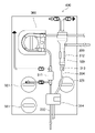
- FIG. 4 is a diagram showing an example layout of a dialysis monitoring device fitted with an extracorporeal circulation circuit having an air trap chamber according to one embodiment.
- 1 is a perspective view of an air trap chamber according to one embodiment;
- FIG. 2 is a side view of an air trap chamber according to one embodiment;
- 4 is a cross-sectional view taken along line IV-IV of FIG. 3;
- FIG. It is a side view which shows an intermediate cap part.
- FIG. 6 is a cross-sectional view taken along the line VI-VI of FIG. 5;
- FIG. 6 is a cross-sectional view taken along line VII-VII of FIG. 5; It is a side view which shows an upper end cap part. It is a bottom view which shows an upper end cap part.
- FIG. 1 is a perspective view of an air trap chamber according to one embodiment
- 2 is a side view of an air trap chamber according to one embodiment
- 4 is a cross-sectional view taken along line IV-IV of FIG. 3;
- FIG. 4 is a cross-sectional view showing an enlarged inflow port of the upper end cap portion;
- FIG. 10 is a diagram showing an example layout of a dialysis monitoring device equipped with a double-needle extracorporeal circulation circuit.
- FIG. 11 is a plan view showing a modification of the arrangement of ports;
- the air trap chamber 100 of the present disclosure is an air trap chamber that can be used in a blood circuit for single-needle dialysis, and is attached to, for example, a dialysis monitor 400 as shown in FIG.
- Air trap chamber 100 is held on dialysis monitor 400 by holders 312 and 313 provided on the sides of dialysis monitor 400 .
- the holder 312 sandwiches and holds the air trap chamber 100 from the side.
- it has a liquid level sensor and can monitor the liquid level in the air trap chamber 100 so that it does not become too low.
- the holder 313 supports the lower end of the air trap chamber 100 to keep the relative positions of the air trap chamber 100 and the liquid level sensor constant so that the liquid level can be properly monitored.
- a pump 300 to which a blood removal side line 202 is attached, a component sensor 311 for analyzing components of the blood flowing through the line 202, lines 202 and 204.
- a clamp portion 314 for opening and closing the dialysate, a plurality of ports 321 for supplying dialysate and the like, and for draining waste fluid are arranged. If the line 202 on the blood removal side can be sufficiently closed by stopping the pump 300, the clamp section 314 may be configured to open and close only the line 202 on the blood return side. Further, a sensor for detecting air bubbles in the line or detecting blood leakage may be provided in the clamp section 314 .
- blood is removed by the pump 300 while the line 204 on the blood return side is closed by the clamp part 314, and the blood is sent to the artificial dialyzer.
- Blood purified by the artificial dialyzer flows into the air trap chamber 100 and is stored therein.
- the purified blood in the air trap chamber 100 is returned to the patient's body. Depending on the flow velocity, this operation is repeated every few seconds to several tens of seconds.
- the air trap chamber 100 has a cylindrical chamber main body 101 and a trap filter 141 provided therein.
- the chamber body 101 is composed of a first member 132, a lower end cap portion 131 connected to the lower end of the first member 132, and a second member 133 and an upper end cap portion 134 connected to the upper end.
- the second member 133 has a small diameter portion 133C to which the first member 132 is connected, and a large diameter portion 133A to which the upper end cap portion 134 is connected.
- a diameter-reduced portion 133B that gradually reduces in diameter is provided.
- the small diameter portion 133C is provided with an inflow port 121 to which the line 203 on the inflow side is connected and into which blood flows.
- the upper end cap portion 134 has a connecting portion 134A fitted onto the second member 133, a side wall portion 134B, and a top plate portion 134C. there is
- the lower end of the lower end cap portion 131 serves as an outflow port 122 that connects the line 204 on the blood return side, and a trap filter 141 is fixed inside the lower end cap portion 131 .
- the blood that has flowed into the chamber from the inflow port 121 passes through the trap filter 141 and flows out from the outflow port 122 .
- a large diameter portion 111 is formed by the large diameter portion 133A of the second member 133 and the upper end cap portion 134, and a small diameter portion 113 is formed by the small diameter portion 133C of the second member 133, the first member 132 and the upper portion of the lower end cap portion 131.
- the intermediate portion 112 is formed by the reduced diameter portion 133B of the second member 133. As shown in FIG. In the present disclosure, the large-diameter portion 111 and the intermediate portion 112 are defined as a first space, and the small-diameter portion 113 closer to the outflow port than the first space is defined as a second space.
- the outer diameter and inner diameter of the small-diameter portion 113 are approximately equal to the outer diameter and inner diameter of an air trap chamber of a blood circuit used in a normal hemodialysis method in which two punctures are made to simultaneously remove and return blood.
- the dialysis monitoring device 400 is attached to a holder 312 provided with a liquid level sensor so as to sandwich the air trap chamber, and monitors the liquid level in the chamber.
- the holder 312 is provided with a liquid level sensor for controlling the liquid level during priming and a liquid level sensor for monitoring the liquid level in the air trap chamber in the single needle method.
- the volume required for the air trap chamber to retain blood during blood removal is about 1.5 to 3 times the volume required in normal hemodialysis. . If the inner and outer diameters of the entire air trap chamber were the same as in a conventional double-needle hemodialysis method, the length of the air trap chamber would be very long.
- the air trap chamber 100 of this embodiment has a large diameter portion 111 having an inner diameter larger than that of the small diameter portion 113 . Therefore, the volume of the air trap chamber can be increased while reducing the length of the air trap chamber.
- the inner diameter of the large diameter portion 111 can be set according to the required volume of the chamber, but from the viewpoint of increasing the volume while suppressing the length, it is preferably 1.5 times or more, more preferably 1.5 times the inner diameter of the small diameter portion 113. 2.2 times or more.
- the inner diameter of the large-diameter portion 111 is preferably 3 times or less, more preferably 2.8 times or less, the inner diameter of the small-diameter portion 113 from the viewpoint of preventing the distorted shape from making it difficult to attach to the dialysis monitoring device. is.
- the length of the large diameter portion 111 can be set according to the required volume of the chamber. It is below.
- the length of the small diameter portion 113 is preferably 20% or more, more preferably 25% or more.
- the volume of the large diameter portion 111 is preferably 30% or more, more preferably 40% or more, of the total volume of the chamber main body 101 .
- the volume of the large diameter portion 111 is preferably 70% or less, more preferably 60% or less, of the total volume of the chamber body 101 .
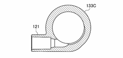
- the inflow port 121 is provided on the side surface of the small diameter portion 113 so as to protrude along the tangential direction of the circumference of the small diameter portion 113 . If the inflow port is provided vertically at the upper end of the chamber, the falling blood is more likely to collide with the liquid surface and foam or hemolyze. In addition, if a port is provided perpendicularly to the circumference of the small-diameter portion 113, the pulsating blood may spurt out from the port and collide with the wall on the opposite side, or fall vertically without passing through the wall. There is By extending the inflow port 121 in the tangential direction of the circumference, it is possible to move the inside of the chamber spirally along the inner wall surface, and it is possible to prevent bubbling and hemolysis from occurring.
- the radius R is slightly increased in the portion of the inner wall surface of the small-diameter portion 133C that is about 1/4 of the circumference where the inflow port 121 is connected.
- the liquid surface in the chamber is positioned within the large-diameter portion 111 above the inflow port 121 at the end of the blood removal operation, At the start of operation, it is located within the small diameter portion 113 below the inflow port 121 . At this time, the distance between the liquid surface and the top surface of the trap filter 141 is about 1 cm to 3 cm.
- the blood that has flowed in from the inflow port 121 heads toward the small diameter portion 113 while swirling along the tube wall. If the inflow port 121 is provided in the large-diameter portion 133A or the reduced-diameter portion 133B, which is an inclined surface, the blood flow passes through the portion where the angle of inclination changes. There is a current that tries to go to This entrains air and causes foaming, which causes thrombus. Further, when the inflow port 121 is provided in the diameter-reduced portion 133B, a blood flow that runs upward along the inner surface of the diameter-reduced portion 133B is likely to occur.
- the reduced diameter portion 133B and the large diameter portion 133A are present above the inflow port 121, bubbles are generated due to the collision between the replacement fluid and the medicine introduced from the ports 123 and 124 provided in the top plate portion 134C and the liquid surface. is relatively difficult to reach the small-diameter portion 133C, and the position of the inflow port 121 above the small-diameter portion 133C makes it easier to mix replacement fluids or drugs with blood.
- FIG. 11 shows an example in which an extracorporeal circulation circuit for the double needle method is attached to a dialysis monitor 400 instead of the air trap chamber 100 of this embodiment.
- the air trap chamber 102 for the double-needle method and the air trap chamber 100 of the present embodiment have substantially the same structure below the inflow port 121 . Both air trap chambers can thus be held by holders 312 and 313 . Also, monitoring of the liquid level in the air trap chamber can be done in the same way.
- the inner diameter of the large diameter portion 111 is 1.5 times or more and 3 times or less than the inner diameter of the small diameter portion 113, and the length of the large diameter portion 111 is equal to that of the small diameter portion 113. 20% or more and 70% or less of the length of
- the holders 312 and 313 of the illustrated dialysis monitoring device 400 are designed to facilitate attachment of both the air trap chamber 100 of this embodiment and the air trap chamber for the double needle method.
- the air trap chamber 100 of the present embodiment is not limited to a dialysis monitoring device designed so that both air trap chambers can be attached. It can also be attached to a monitoring device.
- the position of the inflow port 121 is not particularly limited, it is preferably provided near the upper end of the small diameter portion 133C. Also, the inflow port 121 is preferably provided below 50% and above 15% of the height of the second member 133 . By doing so, the overlapping portion between the first member 132 and the second member 133 can be secured, and the connection strength can be increased. In addition, between the large-diameter portion 133A and the small-diameter portion 133C, a diameter-reduced portion 133B having a sufficient height is secured, and an inclination is secured between the large-diameter portion 133A and the small-diameter portion 133C to eliminate a sharp step. To prevent air bubbles from occurring and smooth blood flow to reduce a situation in which air bubbles adhere to and remain on steps.
- the small diameter portion 113 formed by the first member 132 and the small diameter portion 133C of the second member 133 has a straight shape with a constant inner diameter.
- the small diameter portion 113 may have a tapered shape in which the diameter gradually decreases toward the lower end side.
- the small diameter portion 113 may have a plurality of portions with different inclination angles. It may also have a straight portion and a tapered portion.
- the large-diameter portion 133A and the reduced-diameter portion 133B of the second member 133 are provided with ribs 136 that are thicker than the other portions.
- the ribs 136 By providing the ribs 136, the strength of the large-diameter portion 111 and the intermediate portion 112 can be ensured, and the large-diameter portion 111 can be made difficult to deform when blood is stored.
- the mold is designed so that the injection gate of the molding mold is positioned at the rib 136 portion, and the injection gate mark 137 is produced at the rib 136 portion. With such a configuration, pinholes are less likely to occur when the second member 133 is released from the mold.
- the rib 136 can also be configured to extend toward the small diameter portion 133C.
- a port 123 provided at the upper end of the air trap chamber 100 of this embodiment is a liquid introduction port for supplying a chemical liquid.
- the port 123 protrudes upward from the top plate portion 134C of the upper end cap portion 134, includes a connection portion 123A to which a tube is connected, and a liquid introducing cylinder 123B protruding into the large diameter portion 111.
- the liquid introducing tube 123B has a tubular shape with an upper end communicating with the connecting portion 123A and a lower end closed.
- the port 123 is provided near the periphery of the top plate portion 134C, and part of the side surface of the liquid introduction tube 123B is in contact with the inner wall surface of the side wall portion 134B.
- a side surface of the liquid guide tube 123B is partially cut away to form a side opening 123a. Therefore, the chemical liquid injected from the liquid introduction port 123 does not fall from the lower end of the liquid introduction cylinder 123B toward the liquid surface, but rather flows from the side opening 123a along the inner wall surface of the large diameter portion 111 and reaches the liquid surface. reach. Therefore, the blood in the chamber is less likely to bubble or hemolyze due to the falling liquid medicine. Further, when the top plate portion 134C is viewed from the bottom (liquid guide tube 123B) side, the direction in which the opening surface of the side opening 123a extends and the line connecting the centers of the top plate portion 134C and the liquid guide tube 123B.
- the angle ⁇ 1 formed with the extending direction can be preferably about ⁇ 30° to 30°, more preferably about ⁇ 10° to 10°. If ⁇ 1 is made larger than 0 so that the angle ⁇ 2 between the opening surface and the inner wall surface is less than 90°, the liquid discharged from the side opening 123a is more likely to face the inner wall surface of the side wall portion 134B. preferable. In addition, it is set to 5 degrees in this embodiment. By doing so, the liquid discharged from the side opening 123a can more reliably flow along the inner wall surface of the side wall portion 134B.
- the length of the side opening 123a which is the chord of the liquid guide tube 123B, is preferably about 1/3 to 2/3 of the diameter of the liquid guide tube 123B.
- a port 124 is provided in addition to the port 123 at the upper end of the air trap chamber 100 of this embodiment.
- the port 124 does not have a liquid introduction cylinder protruding into the large-diameter portion 111, and can be connected to a liquid level adjustment line, a pressure measurement line, and the like.
- the number of ports provided in the top plate portion 134C is not limited, and a plurality of ports 123 for liquid introduction may be provided, or two or more ports 124 used for adjustment or the like may be provided.
- the port 123 for liquid introduction may be provided as required, and may not be provided.
- injection gate marks 138 are present at two locations on the surface of the top plate portion 134C.
- pinholes are less likely to occur when the upper end cap portion 134 is released from the mold.
- the first member 132 has great flexibility so that it can be easily attached to the holders 312 and 313 of the dialysis monitoring device 400 .
- the second member 133 provided with the blood inflow port 121 has less flexibility than the first member 132 so as not to be greatly deformed when the blood is stored.
- the air trap chamber 100 may be hit with forceps or the like. In most cases, damage can be prevented.
- the first member 132 can be relatively thin to increase flexibility, and the second member 133 can be molded thicker than the first member 132 to decrease flexibility.
- the first member 132 and the second member 133 can be made of a material whose modulus can be adjusted, such as vinyl chloride, styrene-based elastomer, and olefin-based elastomer. It should be noted that the first member 132 and the second member 133 may be integrally molded instead of separately formed and assembled. The integral molding eliminates the need for assembly and simplifies the manufacturing process. Alternatively, the first member 132 and the lower end cap portion 131 may be integrally molded.
- the trap filter 141 is provided to remove foreign substances and aggregates, and its shape, material and mounting method are not particularly limited, and the same trap filter used in a normal air trap chamber can be used. can.
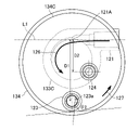
- the blood flowing in from the inflow port 121 formed on the side surface of the air trap chamber 100 forms a swirling blood flow 126 along the inner wall of the air trap chamber 100 in the first direction.
- the swirl direction of the drug solution flow 127 of the drug solution introduced from the port 123 having the liquid guide tube 123B is the first direction, coinciding with the direction of the blood flow 126 .
- turbulence is less likely to occur than when the liquid medicine drops vertically from the liquid guide tube 123B or when the liquid medicine is introduced so as to swirl in the direction opposite to the blood flow 126 .
- the medicinal solution and blood can be mixed quickly and uniformly, and the generation of air bubbles and entrainment of the generated air bubbles can be prevented.
- the blood flow 126 turns counterclockwise.
- the side wall is cut so as to include the farthest counterclockwise position from the inflow port 121 in the liquid guide tube 123B, and the side opening 123a is formed. can be formed.
- the side opening 123a can be formed by notching the side wall so as to include the position of the liquid introducing tube 123B that is the furthest clockwise from the inflow port 121 .
- the angle ⁇ 2 formed by the opening surface of the side opening 123a and the inner wall surface of the chamber body 101 is preferably smaller than 90°.
- ⁇ 2 is an angle formed by a tangent line to the inner wall surface at the position where the extension line of the opening surface intersects the inner wall surface of the chamber main body 101 and the extension line of the opening surface.
- the side opening 123a of the port 123 for introducing the drug solution is preferably formed above the inflow port 121 for blood.
- the side opening 123a can be located in the first space, which is the combination of the large diameter portion 111 and the intermediate portion 112, and the inflow port 121 can be located in the second space, which is the small diameter portion 113.
- simulations were conducted to compare the mixing of replacement fluid between a chamber having a large-diameter first space and a chamber having a constant diameter. It was found that a layer of the replacement fluid was more easily formed on the top when the replacement fluid was supplied.
- the replacement fluid layer is not limited to a layer containing no blood at all, and includes a layer with a low blood concentration.
- the inclination angle of the inner surface of the intermediate portion 112 is preferably 60° or less. ° or less is more preferable.
- the speed at which the drug solution introduced from the port 123 collides with the blood flowing from the inflow port 121 can be reduced, so that a layer of replacement fluid is likely to be formed on the blood layer.
- the inclination angle is preferably 20° or more, more preferably 30° or more.
- FIG. 12 shows an air trap chamber above the inflow port 121 that has a large-diameter portion that can store blood and that can be used for single-needle dialysis.
- the liquid medicine is discharged so as to swirl along the swirling direction of the blood flow 126, thereby smoothly mixing the liquid medicine and the blood. It can be carried out.
- the port 123 for introducing a liquid such as a chemical solution is preferably positioned on the front side of the top plate portion 134C when used, but can be formed at any position on the top plate portion 134C.
- the port 123 for introducing a liquid such as a chemical solution is formed at a position close to the inflow port 121 on the top plate portion (on the back side of the top plate portion when used), although the handling of the chemical solution introduction line is reduced. You may Regardless of the position where the port 123 is formed, it is preferable to form the side opening 123a so that the swirling direction of the blood flowing in from the inflow port 121 and the swirling direction of the liquid flowing in from the port 123 are the same.
- the port for introducing the chemical solution can be formed on the side surface of the chamber main body 101 in the same manner as the inflow port 121, although the handling of the chemical solution introduction line is reduced. Also when the port for introducing the liquid medicine is formed on the side surface of the chamber main body 101, it is preferable that the swirling direction of the blood flow matches the swirling direction of the liquid medicine flow. Moreover, it is preferable to form the drug introduction port above the blood inflow port 121 .
- the port 123 for introducing the liquid medicine is formed in the top plate portion 134C
- its position is not particularly limited.
- the distance D1 between the port 123 for introducing the chemical solution and the axis L1 of the inflow port 121 is the same as the port 124 for pressure measurement and the inflow port 121.
- the chemical solution introduction port 123 and the pressure measurement port 124 are arranged in the direction in which the inflow port 121 extends.
- the port 123 for introducing the chemical solution is located closer to the front than the port 124 for pressure measurement, etc. ing.
- the distance between the inflow port 121 and the center of the top plate portion 134C is smaller than the distance between the chemical solution introduction port 123 and the center of the top plate portion 134C.
- 121 is provided so as to be located on the opposite side across the center of the top plate portion 134C.
- the projection direction of the inflow port 121 is set to be substantially parallel to the wall surface of the dialysis monitoring device 400 so that the inflow side line 203 does not interfere with the dialysis monitoring device 400.
- the port 123 farther from the axis L1 of the inflow port 121 will be closer to the front than the port 124 closer to it. Therefore, operations such as supplying the chemical solution to the port 123 are facilitated, and operability is improved.
- the direction connecting the connection position 121A of the inflow port 121 and the center of the port 123 is preferably ⁇ 45 with respect to the direction connecting the connection position 121A of the inflow port 121 and the center of the top plate portion 134C.
- the port 123 is preferably formed at the outer edge of the top plate portion 134C so as to be within the range of about ⁇ 15°, more preferably about ⁇ 15°.
- a port 124 to which a pressure measurement line or the like can be connected is preferably formed between the inflow ports 121 and 123 and at a position shifted in the direction in which the inflow port 121 protrudes from the line connecting the inflow ports 121 and 123. .
- the position of the transducer connecting the pressure measurement line in the dialysis monitoring device 400 is generally on the opposite side of the pump because it is advantageous for downsizing the dialysis monitoring device 400 .
- the port 124 is connected to the pump.
- the pressure measurement line can be connected to the dialysis monitoring device 400 more easily.
- a pressure measurement line can be connected to the port 124, but other lines such as a liquid level adjustment line can also be connected.
- FIG. 12 shows an example in which the top plate portion 134C is formed with a port 123 having a liquid guide tube 123B for introducing a chemical solution and a port 124 without a liquid guide tube. A configuration in which other ports are formed is also possible. Also, in the case of a dialysis monitoring device in which the pump is provided on the right side and the blood purifier is arranged on the left side, an air trap chamber in which each port is mirror-symmetrical can be used.
- An air trap chamber having a large diameter portion capable of retaining blood above the inflow port can be used in single-needle dialysis, but can also be used in normal double-needle dialysis.
- the air trap chamber of the present disclosure has excellent functionality and can be used for blood circuits for dialysis and the like.
Landscapes
- Health & Medical Sciences (AREA)
- Heart & Thoracic Surgery (AREA)
- Vascular Medicine (AREA)
- Biomedical Technology (AREA)
- Engineering & Computer Science (AREA)
- Anesthesiology (AREA)
- Cardiology (AREA)
- Hematology (AREA)
- Life Sciences & Earth Sciences (AREA)
- Animal Behavior & Ethology (AREA)
- General Health & Medical Sciences (AREA)
- Public Health (AREA)
- Veterinary Medicine (AREA)
- External Artificial Organs (AREA)
Priority Applications (1)
| Application Number | Priority Date | Filing Date | Title |
|---|---|---|---|
| JP2023503954A JPWO2022186352A1 (https=) | 2021-03-04 | 2022-03-03 |
Applications Claiming Priority (2)
| Application Number | Priority Date | Filing Date | Title |
|---|---|---|---|
| JP2021034638 | 2021-03-04 | ||
| JP2021-034638 | 2021-03-04 |
Publications (1)
| Publication Number | Publication Date |
|---|---|
| WO2022186352A1 true WO2022186352A1 (ja) | 2022-09-09 |
Family
ID=83155393
Family Applications (1)
| Application Number | Title | Priority Date | Filing Date |
|---|---|---|---|
| PCT/JP2022/009216 Ceased WO2022186352A1 (ja) | 2021-03-04 | 2022-03-03 | エアトラップチャンバ |
Country Status (2)
| Country | Link |
|---|---|
| JP (1) | JPWO2022186352A1 (https=) |
| WO (1) | WO2022186352A1 (https=) |
Cited By (1)
| Publication number | Priority date | Publication date | Assignee | Title |
|---|---|---|---|---|
| WO2025182730A1 (ja) * | 2024-02-27 | 2025-09-04 | 旭化成メディカル株式会社 | チャンバとそれを含む血液回路、および血液浄化装置 |
Citations (6)
| Publication number | Priority date | Publication date | Assignee | Title |
|---|---|---|---|---|
| JPS5836606A (ja) * | 1981-08-26 | 1983-03-03 | Ishikawajima Harima Heavy Ind Co Ltd | 流体中の気泡集合方法 |
| JP2012095841A (ja) * | 2010-11-02 | 2012-05-24 | Nikkiso Co Ltd | エアートラップチャンバ |
| JP2015085181A (ja) * | 2013-09-25 | 2015-05-07 | 川澄化学工業株式会社 | ドリップチャンバ |
| JP2016158921A (ja) * | 2015-03-03 | 2016-09-05 | 日機装株式会社 | エアトラップチャンバ |
| JP2019068950A (ja) * | 2017-10-06 | 2019-05-09 | ニプロ株式会社 | 圧力測定用容器および血液浄化装置 |
| JP2019193736A (ja) * | 2018-05-02 | 2019-11-07 | 日機装株式会社 | エアトラップチャンバ及び体外循環回路 |
-
2022
- 2022-03-03 JP JP2023503954A patent/JPWO2022186352A1/ja active Pending
- 2022-03-03 WO PCT/JP2022/009216 patent/WO2022186352A1/ja not_active Ceased
Patent Citations (6)
| Publication number | Priority date | Publication date | Assignee | Title |
|---|---|---|---|---|
| JPS5836606A (ja) * | 1981-08-26 | 1983-03-03 | Ishikawajima Harima Heavy Ind Co Ltd | 流体中の気泡集合方法 |
| JP2012095841A (ja) * | 2010-11-02 | 2012-05-24 | Nikkiso Co Ltd | エアートラップチャンバ |
| JP2015085181A (ja) * | 2013-09-25 | 2015-05-07 | 川澄化学工業株式会社 | ドリップチャンバ |
| JP2016158921A (ja) * | 2015-03-03 | 2016-09-05 | 日機装株式会社 | エアトラップチャンバ |
| JP2019068950A (ja) * | 2017-10-06 | 2019-05-09 | ニプロ株式会社 | 圧力測定用容器および血液浄化装置 |
| JP2019193736A (ja) * | 2018-05-02 | 2019-11-07 | 日機装株式会社 | エアトラップチャンバ及び体外循環回路 |
Cited By (1)
| Publication number | Priority date | Publication date | Assignee | Title |
|---|---|---|---|---|
| WO2025182730A1 (ja) * | 2024-02-27 | 2025-09-04 | 旭化成メディカル株式会社 | チャンバとそれを含む血液回路、および血液浄化装置 |
Also Published As
| Publication number | Publication date |
|---|---|
| JPWO2022186352A1 (https=) | 2022-09-09 |
Similar Documents
| Publication | Publication Date | Title |
|---|---|---|
| AU2016203674B2 (en) | External functional device, blood treatment apparatus for accommodating such an external functional device, and methods | |
| JP5806296B2 (ja) | バイアルの接続のために改良されたゲートを有するチューブセット | |
| CN100586494C (zh) | 整体化血液处理模块 | |
| EP0568265A2 (en) | Blow molded venous drip chamber for hemodialysis | |
| US7025750B2 (en) | Set for blood processing | |
| KR101118380B1 (ko) | 탈기 장치 및 이 탈기 장치를 포함하는 필터용 단부 캡조립체 | |
| WO2008140395A1 (en) | Pressure sensing device and use of the same in a connecting structure | |
| JP6076390B2 (ja) | 薬物の注入のためのインサートを有する配管セット | |
| EP3266477B1 (en) | Air trap chamber | |
| CN101516433A (zh) | 体外流体管路 | |
| CN103402560B (zh) | 用于血液处理系统的腔室、腔室用途、血液导管系统和血液处理系统 | |
| KR20190001420U (ko) | 원 웨이 밸브를 포함한 수액필터 | |
| WO2022186352A1 (ja) | エアトラップチャンバ | |
| JP2008149076A (ja) | 液体貯留容器及び液体採取器具並びに採血初流除去容器、採血器具及び血液容器 | |
| US20060173395A1 (en) | Set for blood processing | |
| JP2021007419A (ja) | 貯血槽 | |
| EP3789057B1 (en) | Air trap chamber and extracorporeal circulation circuit | |
| CN112020373B (zh) | 空气阱室和体外循环回路 | |
| JP5128200B2 (ja) | 混注部材 | |
| EP3842086B1 (en) | Tube connector, extracorporeal circulation circuit, and blood purification device | |
| JP3135582U (ja) | ドリップチャンバ、およびドリップチャンバを備えた血液回路 | |
| JP5078122B2 (ja) | 血液浄化装置 | |
| JP5255344B2 (ja) | 混注部材 | |
| JP2017225534A (ja) | 貯血槽 | |
| WO2022158466A1 (ja) | 貯血槽 |
Legal Events
| Date | Code | Title | Description |
|---|---|---|---|
| 121 | Ep: the epo has been informed by wipo that ep was designated in this application |
Ref document number: 22763404 Country of ref document: EP Kind code of ref document: A1 |
|
| WWE | Wipo information: entry into national phase |
Ref document number: 2023503954 Country of ref document: JP |
|
| NENP | Non-entry into the national phase |
Ref country code: DE |
|
| 122 | Ep: pct application non-entry in european phase |
Ref document number: 22763404 Country of ref document: EP Kind code of ref document: A1 |