WO2022186352A1 - Air trap chamber - Google Patents
Air trap chamber Download PDFInfo
- Publication number
- WO2022186352A1 WO2022186352A1 PCT/JP2022/009216 JP2022009216W WO2022186352A1 WO 2022186352 A1 WO2022186352 A1 WO 2022186352A1 JP 2022009216 W JP2022009216 W JP 2022009216W WO 2022186352 A1 WO2022186352 A1 WO 2022186352A1
- Authority
- WO
- WIPO (PCT)
- Prior art keywords
- diameter portion
- port
- chamber
- blood
- inflow port
- Prior art date
Links
- 239000008280 blood Substances 0.000 claims abstract description 121
- 210000004369 blood Anatomy 0.000 claims abstract description 121
- 239000007788 liquid Substances 0.000 claims description 120
- 238000009530 blood pressure measurement Methods 0.000 claims description 24
- 238000000502 dialysis Methods 0.000 description 57
- 239000003814 drug Substances 0.000 description 27
- 238000012806 monitoring device Methods 0.000 description 27
- 239000000243 solution Substances 0.000 description 23
- 230000017531 blood circulation Effects 0.000 description 20
- 239000012530 fluid Substances 0.000 description 18
- 238000000034 method Methods 0.000 description 18
- 239000000126 substance Substances 0.000 description 15
- 229940079593 drug Drugs 0.000 description 14
- 230000004087 circulation Effects 0.000 description 7
- 238000002347 injection Methods 0.000 description 6
- 239000007924 injection Substances 0.000 description 6
- 238000001631 haemodialysis Methods 0.000 description 4
- 230000000322 hemodialysis Effects 0.000 description 4
- 206010018910 Haemolysis Diseases 0.000 description 3
- 230000008588 hemolysis Effects 0.000 description 3
- 238000012544 monitoring process Methods 0.000 description 3
- 230000037452 priming Effects 0.000 description 3
- PPBRXRYQALVLMV-UHFFFAOYSA-N Styrene Chemical compound C=CC1=CC=CC=C1 PPBRXRYQALVLMV-UHFFFAOYSA-N 0.000 description 2
- 230000007423 decrease Effects 0.000 description 2
- 238000010586 diagram Methods 0.000 description 2
- 238000005187 foaming Methods 0.000 description 2
- 239000000463 material Substances 0.000 description 2
- 238000000465 moulding Methods 0.000 description 2
- 208000007536 Thrombosis Diseases 0.000 description 1
- BZHJMEDXRYGGRV-UHFFFAOYSA-N Vinyl chloride Chemical compound ClC=C BZHJMEDXRYGGRV-UHFFFAOYSA-N 0.000 description 1
- 230000005587 bubbling Effects 0.000 description 1
- 230000003247 decreasing effect Effects 0.000 description 1
- 229920001971 elastomer Polymers 0.000 description 1
- 239000000806 elastomer Substances 0.000 description 1
- 239000006260 foam Substances 0.000 description 1
- 238000001990 intravenous administration Methods 0.000 description 1
- 230000003907 kidney function Effects 0.000 description 1
- 238000004519 manufacturing process Methods 0.000 description 1
- 238000005259 measurement Methods 0.000 description 1
- 239000000203 mixture Substances 0.000 description 1
- 230000004048 modification Effects 0.000 description 1
- 238000012986 modification Methods 0.000 description 1
- 229920006124 polyolefin elastomer Polymers 0.000 description 1
- 238000000746 purification Methods 0.000 description 1
- 230000000717 retained effect Effects 0.000 description 1
- 238000010079 rubber tapping Methods 0.000 description 1
- 238000004088 simulation Methods 0.000 description 1
- 230000002195 synergetic effect Effects 0.000 description 1
- 239000002699 waste material Substances 0.000 description 1
Images


Classifications
-
- A—HUMAN NECESSITIES
- A61—MEDICAL OR VETERINARY SCIENCE; HYGIENE
- A61M—DEVICES FOR INTRODUCING MEDIA INTO, OR ONTO, THE BODY; DEVICES FOR TRANSDUCING BODY MEDIA OR FOR TAKING MEDIA FROM THE BODY; DEVICES FOR PRODUCING OR ENDING SLEEP OR STUPOR
- A61M1/00—Suction or pumping devices for medical purposes; Devices for carrying-off, for treatment of, or for carrying-over, body-liquids; Drainage systems
- A61M1/36—Other treatment of blood in a by-pass of the natural circulatory system, e.g. temperature adaptation, irradiation ; Extra-corporeal blood circuits
Definitions
- the present disclosure relates to air trap chambers.
- An extracorporeal circuit for artificial dialysis is provided with an air trap chamber for removing air bubbles from the blood.
- the air trap chamber has a cylindrical shape with a filter provided at the lower end, and the blood flowed in from the inlet at the upper end passes through the filter and flows out from the outlet at the lower end.
- Normal artificial dialysis is performed by puncturing in two places and securing two routes for blood withdrawal and blood return.
- single-needle dialysis is used.
- a branched puncture needle is connected to a blood removal side line and a blood return side line of an extracorporeal circulation circuit.
- Blood removal and purification are performed with the blood return line closed, and when a predetermined amount of blood has been removed and purified, the blood removal line is closed and the purified blood is returned from the blood return line. The action of blood removal and blood return is repeated every few seconds.
- An air trap chamber is also provided in the extracorporeal circulation circuit for single-needle dialysis, just like an ordinary extracorporeal circulation circuit that performs punctures at two locations.
- the air trap chamber is continuously filled with blood because blood is not returned during blood removal.
- an extracorporeal circulation circuit for single-needle dialysis uses an air trap chamber with a larger diameter and larger internal capacity than a normal hemodialysis circuit (see, for example, Patent Document 1).
- Dialysis monitoring devices are required to be able to support not only the usual double-needle dialysis method, but also the single-needle dialysis method. For this reason, the dialysis monitoring device is provided with a separate holder for fixing the air trap chamber for the double-needle dialysis method and a holder for fixing the large-diameter air trap chamber for the single-needle dialysis method. This is a factor in increasing the size of the monitoring device.
- the pump operates to store the blood purified by the blood purifier in the chamber. After the storage is completed, the pump stops, air is sent out from the upper part of the chamber, and the stored blood is delivered to the patient. When the liquid level drops to the vicinity of the liquid level sensor, the air stops and the storage operation resumes. Dialysis treatment is performed by repeating such an operation, but the fluctuation of the liquid level is repeated periodically. Hemolysis may occur.
- fluids may be replenished and drugs may be administered on the intravenous side.
- drugs may be administered on the intravenous side.
- the replacement fluid or other medical fluid is mixed with the blood in the air trap chamber, the medical fluid collides with the blood surface to generate air bubbles, which entrain the air bubbles.
- the mixed liquid medicine mixes with the blood quickly and uniformly, there may arise a problem that the blood and the liquid medicine do not mix quickly in the air trap chamber.
- the chamber for single-needle dialysis which temporarily stores the purified blood, is large, depending on the port arrangement, it may interfere with the handling of the line tube or interfere with the administration of the drug solution. There is also a problem.
- An object of the present disclosure is to solve at least one of these problems and realize an air trap chamber with excellent functionality.
- a first aspect of the air trap chamber of the present disclosure comprises a tubular chamber body having a blood inflow port and a blood outflow port, the chamber body having a large diameter portion and a smaller diameter than the large diameter portion, It has a small diameter portion provided on the outflow port side, and an intermediate portion provided between the large diameter portion and the small diameter portion and having a gradually changing diameter, and the inflow port is located at the end of the intermediate portion side of the small diameter portion. It is provided on the side surface so as to extend in the tangential direction of the circumference of the small diameter portion.
- the chamber body has a large diameter portion and a small diameter portion smaller in diameter than the large diameter portion and provided on the outflow port side. Therefore, a sufficient capacity of the chamber can be secured. Furthermore, since the inflow port is provided so as to extend tangentially to the circumference of the small-diameter portion, collision between the blood and the liquid surface is avoided, and the blood is less likely to bubble or hemolyze. In addition, the blood that has flowed in from the inflow port flows along the side of the chamber, causing a rotating flow. Since the inflow port is located at the small diameter part, even if the liquid level rises and falls, it is easy to maintain the state in which the rotating flow is generated. can.
- a second aspect of the air trap chamber comprises a cylindrical chamber body having a blood inflow port and an outflow port, the chamber body having a large diameter portion and a smaller diameter than the large diameter portion, and the outflow port side. and an intermediate portion provided between the large diameter portion and the small diameter portion, the diameter of which gradually changes, and the inner diameter of the large diameter portion is 1.5 times or more the inner diameter of the small diameter portion, 3 times or less, and the length of the large diameter portion is 20% or more and 70% or less of the length of the small diameter portion.
- the inner diameter of the large diameter portion is 1.5 times or more and 3 times or less the inner diameter of the small diameter portion
- the length of the large diameter portion is 20% or more of the length of the small diameter portion
- a third aspect of the air trap chamber comprises a tubular chamber body having a blood inflow port and an outflow port, the chamber body having a large diameter portion and a smaller diameter than the large diameter portion, and the outflow port side. and an intermediate portion provided between the large-diameter portion and the small-diameter portion, the diameter of which gradually changes, and the volume of the large-diameter portion is 30% or more and 70% of the volume of the chamber body. It is below.
- the chamber body has a large diameter portion and a small diameter portion smaller in diameter than the large diameter portion and provided on the outflow port side, the volume of the large diameter portion being equal to the volume of the chamber body 30% or more and 70% or less of the volume of Therefore, it is possible to reduce the diameter of the small-diameter portion and shorten the total length of the chamber while ensuring the capacity of the chamber, and to easily attach the chamber to the dialysis monitoring device.
- the large diameter portion has a liquid introduction port, and the inflow port is positioned above the small diameter portion. Since the small-diameter portion and the large-diameter portion are separated from each other through the intermediate portion, the intermediate portion makes it difficult for the air bubbles generated by the replacement fluid flowing from the large-diameter portion to collide with the liquid surface to reach downward.
- the inflow port is located in the middle part, the blood flow becomes a flow that runs up along the inner surface of the middle part, and there is a possibility that the liquid surface will ripple out due to the upward and downward movement of the liquid surface. Occurrence of such a situation can be reduced by being in the small diameter portion.
- the inflow port is positioned above the small-diameter portion, the medicine and replacement fluid flowing in from the liquid introduction port can be easily mixed with the blood flow, and the mixed fluid can be easily returned to the patient.
- the chamber body has a first member that constitutes at least part of the small-diameter portion, and a second member that includes the large-diameter portion, the intermediate portion, and the inflow port, the first member comprising: It may be more flexible than the second member.
- the first member is more flexible than the second member, it is possible to prevent damage from occurring when air bubbles are removed by tapping with forceps or the like during priming.
- the small diameter portion is used as the attachment portion, the flexibility of the small diameter portion to be attached to the dialysis monitoring device is secured, and the strength of the entire chamber is secured, so that even if blood is accumulated inside the chamber, deformation will not occur. can be made less likely to occur.
- the chamber body may have ribs formed on the outer surface over at least part of the intermediate portion and the large diameter portion.
- a fourth aspect of the air trap chamber of the present disclosure includes a tubular chamber body having a blood inflow port, an outflow port, and a liquid introduction port, wherein the chamber body includes a first space and a and a second space provided on the outflow port side, the first space is formed to have a larger diameter than the second space, the inflow port of the liquid introduction port is located in the first space, and the inflow port of the blood The inflow port is located in the second space, and the blood flowing in from the inflow port and the liquid flowing in from the liquid introduction port are guided along the inner wall surface of the chamber main body so as to swirl in the first direction.
- blood flowing in from the inflow port and liquid flowing in from the liquid introduction port are guided along the inner wall surface of the chamber main body so as to swirl in the first direction. Therefore, turbulence is less likely to occur in the chamber main body, blood and liquid are rapidly and uniformly mixed, and air bubbles are less likely to be generated and entrapment of generated air bubbles to be less likely to occur.
- the inflow port of the liquid introduction port is located in the first space and the inflow port of the blood inflow port is located in the second space, the liquid introduced from the liquid introduction port is placed on the blood layer. A layer is easily formed, and a condition can be easily created in which the blood does not come into direct contact with the air.
- a fifth aspect of the air trap chamber of the present disclosure includes a tubular chamber body having a blood inflow port, an outflow port, and a liquid introduction port, and the inflow port is located on the side surface of the chamber body.
- the liquid introduction port is provided so as to extend in the tangential direction of the circumference, and the liquid introduction port has a liquid introduction cylinder with a closed bottom surface and a side opening that protrudes into the chamber main body from the top plate portion of the chamber main body. Incoming blood and liquid entering from the liquid introduction port are guided to swirl in a first direction along the inner wall surface of the chamber body.
- the side opening provided in the liquid guide tube is open to the downstream side of the blood flow, so the liquid introduced from the liquid guide port flows in the same direction as the blood flow. . Therefore, turbulence is less likely to occur in the chamber main body, blood and liquid are rapidly and uniformly mixed, and air bubbles are less likely to be generated and entrapment of generated air bubbles to be less likely to occur.
- the angle between the side opening and the inner wall surface of the chamber body can be less than 90°.
- a sixth aspect of the air trap chamber of the present disclosure includes a tubular chamber body having a blood inflow port, an outflow port, a liquid introduction port, and a pressure measurement port, wherein the chamber body includes a large diameter portion and a pressure measurement port. , a small diameter portion provided on the outflow port side and having a smaller diameter than the large diameter portion; and an intermediate portion provided between the large diameter portion and the small diameter portion and having a diameter that gradually changes,
- the liquid introduction port and the pressure measurement port are formed on the top plate of the chamber body, and when the top plate is viewed from above, the liquid introduction port and the inflow
- the distance from the axis of the port is greater than the distance between the pressure measurement port and the axis of the inflow port, and the pressure measurement port is located between the inflow port and the liquid introduction port on the top surface and between the inflow port and the liquid introduction port. It is formed at a position shifted in the direction in which the inflow port protrudes from the connecting line.
- the distance between the liquid introduction port and the axis of the inflow port is greater than the distance between the pressure measurement port and the axis of the inflow port when the top plate is viewed from above. Therefore, if the inflow port is arranged on the back side of the dialysis monitoring device so that the line connected to the blood purifier does not get in the way, the liquid introduction port will be on the front side of the pressure measurement port. Therefore, the user can easily administer the liquid medicine using the liquid introduction port.
- the pressure measurement port is provided at a position between the inflow port and the liquid introduction port on the top surface and at a position shifted in the direction in which the inflow port projects from the line connecting the inflow port and the liquid introduction port. The pressure measurement line attached to the measurement port can be easily connected to the dialysis monitoring device, and the pressure measurement line can be easily routed.
- the air trap chamber of the present disclosure it is possible to support single-needle dialysis without complicating the dialysis monitoring device, reduce foaming when introducing the drug solution, and promote mixing of the blood and the drug solution. at least one of the following:
- FIG. 4 is a diagram showing an example layout of a dialysis monitoring device fitted with an extracorporeal circulation circuit having an air trap chamber according to one embodiment.
- 1 is a perspective view of an air trap chamber according to one embodiment;
- FIG. 2 is a side view of an air trap chamber according to one embodiment;
- 4 is a cross-sectional view taken along line IV-IV of FIG. 3;
- FIG. It is a side view which shows an intermediate cap part.
- FIG. 6 is a cross-sectional view taken along the line VI-VI of FIG. 5;
- FIG. 6 is a cross-sectional view taken along line VII-VII of FIG. 5; It is a side view which shows an upper end cap part. It is a bottom view which shows an upper end cap part.
- FIG. 1 is a perspective view of an air trap chamber according to one embodiment
- 2 is a side view of an air trap chamber according to one embodiment
- 4 is a cross-sectional view taken along line IV-IV of FIG. 3;
- FIG. 4 is a cross-sectional view showing an enlarged inflow port of the upper end cap portion;
- FIG. 10 is a diagram showing an example layout of a dialysis monitoring device equipped with a double-needle extracorporeal circulation circuit.
- FIG. 11 is a plan view showing a modification of the arrangement of ports;
- the air trap chamber 100 of the present disclosure is an air trap chamber that can be used in a blood circuit for single-needle dialysis, and is attached to, for example, a dialysis monitor 400 as shown in FIG.
- Air trap chamber 100 is held on dialysis monitor 400 by holders 312 and 313 provided on the sides of dialysis monitor 400 .
- the holder 312 sandwiches and holds the air trap chamber 100 from the side.
- it has a liquid level sensor and can monitor the liquid level in the air trap chamber 100 so that it does not become too low.
- the holder 313 supports the lower end of the air trap chamber 100 to keep the relative positions of the air trap chamber 100 and the liquid level sensor constant so that the liquid level can be properly monitored.
- a pump 300 to which a blood removal side line 202 is attached, a component sensor 311 for analyzing components of the blood flowing through the line 202, lines 202 and 204.
- a clamp portion 314 for opening and closing the dialysate, a plurality of ports 321 for supplying dialysate and the like, and for draining waste fluid are arranged. If the line 202 on the blood removal side can be sufficiently closed by stopping the pump 300, the clamp section 314 may be configured to open and close only the line 202 on the blood return side. Further, a sensor for detecting air bubbles in the line or detecting blood leakage may be provided in the clamp section 314 .
- blood is removed by the pump 300 while the line 204 on the blood return side is closed by the clamp part 314, and the blood is sent to the artificial dialyzer.
- Blood purified by the artificial dialyzer flows into the air trap chamber 100 and is stored therein.
- the purified blood in the air trap chamber 100 is returned to the patient's body. Depending on the flow velocity, this operation is repeated every few seconds to several tens of seconds.
- the air trap chamber 100 has a cylindrical chamber main body 101 and a trap filter 141 provided therein.
- the chamber body 101 is composed of a first member 132, a lower end cap portion 131 connected to the lower end of the first member 132, and a second member 133 and an upper end cap portion 134 connected to the upper end.
- the second member 133 has a small diameter portion 133C to which the first member 132 is connected, and a large diameter portion 133A to which the upper end cap portion 134 is connected.
- a diameter-reduced portion 133B that gradually reduces in diameter is provided.
- the small diameter portion 133C is provided with an inflow port 121 to which the line 203 on the inflow side is connected and into which blood flows.
- the upper end cap portion 134 has a connecting portion 134A fitted onto the second member 133, a side wall portion 134B, and a top plate portion 134C. there is
- the lower end of the lower end cap portion 131 serves as an outflow port 122 that connects the line 204 on the blood return side, and a trap filter 141 is fixed inside the lower end cap portion 131 .
- the blood that has flowed into the chamber from the inflow port 121 passes through the trap filter 141 and flows out from the outflow port 122 .
- a large diameter portion 111 is formed by the large diameter portion 133A of the second member 133 and the upper end cap portion 134, and a small diameter portion 113 is formed by the small diameter portion 133C of the second member 133, the first member 132 and the upper portion of the lower end cap portion 131.
- the intermediate portion 112 is formed by the reduced diameter portion 133B of the second member 133. As shown in FIG. In the present disclosure, the large-diameter portion 111 and the intermediate portion 112 are defined as a first space, and the small-diameter portion 113 closer to the outflow port than the first space is defined as a second space.
- the outer diameter and inner diameter of the small-diameter portion 113 are approximately equal to the outer diameter and inner diameter of an air trap chamber of a blood circuit used in a normal hemodialysis method in which two punctures are made to simultaneously remove and return blood.
- the dialysis monitoring device 400 is attached to a holder 312 provided with a liquid level sensor so as to sandwich the air trap chamber, and monitors the liquid level in the chamber.
- the holder 312 is provided with a liquid level sensor for controlling the liquid level during priming and a liquid level sensor for monitoring the liquid level in the air trap chamber in the single needle method.
- the volume required for the air trap chamber to retain blood during blood removal is about 1.5 to 3 times the volume required in normal hemodialysis. . If the inner and outer diameters of the entire air trap chamber were the same as in a conventional double-needle hemodialysis method, the length of the air trap chamber would be very long.
- the air trap chamber 100 of this embodiment has a large diameter portion 111 having an inner diameter larger than that of the small diameter portion 113 . Therefore, the volume of the air trap chamber can be increased while reducing the length of the air trap chamber.
- the inner diameter of the large diameter portion 111 can be set according to the required volume of the chamber, but from the viewpoint of increasing the volume while suppressing the length, it is preferably 1.5 times or more, more preferably 1.5 times the inner diameter of the small diameter portion 113. 2.2 times or more.
- the inner diameter of the large-diameter portion 111 is preferably 3 times or less, more preferably 2.8 times or less, the inner diameter of the small-diameter portion 113 from the viewpoint of preventing the distorted shape from making it difficult to attach to the dialysis monitoring device. is.
- the length of the large diameter portion 111 can be set according to the required volume of the chamber. It is below.
- the length of the small diameter portion 113 is preferably 20% or more, more preferably 25% or more.
- the volume of the large diameter portion 111 is preferably 30% or more, more preferably 40% or more, of the total volume of the chamber main body 101 .
- the volume of the large diameter portion 111 is preferably 70% or less, more preferably 60% or less, of the total volume of the chamber body 101 .
- the inflow port 121 is provided on the side surface of the small diameter portion 113 so as to protrude along the tangential direction of the circumference of the small diameter portion 113 . If the inflow port is provided vertically at the upper end of the chamber, the falling blood is more likely to collide with the liquid surface and foam or hemolyze. In addition, if a port is provided perpendicularly to the circumference of the small-diameter portion 113, the pulsating blood may spurt out from the port and collide with the wall on the opposite side, or fall vertically without passing through the wall. There is By extending the inflow port 121 in the tangential direction of the circumference, it is possible to move the inside of the chamber spirally along the inner wall surface, and it is possible to prevent bubbling and hemolysis from occurring.
- the radius R is slightly increased in the portion of the inner wall surface of the small-diameter portion 133C that is about 1/4 of the circumference where the inflow port 121 is connected.
- the liquid surface in the chamber is positioned within the large-diameter portion 111 above the inflow port 121 at the end of the blood removal operation, At the start of operation, it is located within the small diameter portion 113 below the inflow port 121 . At this time, the distance between the liquid surface and the top surface of the trap filter 141 is about 1 cm to 3 cm.
- the blood that has flowed in from the inflow port 121 heads toward the small diameter portion 113 while swirling along the tube wall. If the inflow port 121 is provided in the large-diameter portion 133A or the reduced-diameter portion 133B, which is an inclined surface, the blood flow passes through the portion where the angle of inclination changes. There is a current that tries to go to This entrains air and causes foaming, which causes thrombus. Further, when the inflow port 121 is provided in the diameter-reduced portion 133B, a blood flow that runs upward along the inner surface of the diameter-reduced portion 133B is likely to occur.
- the reduced diameter portion 133B and the large diameter portion 133A are present above the inflow port 121, bubbles are generated due to the collision between the replacement fluid and the medicine introduced from the ports 123 and 124 provided in the top plate portion 134C and the liquid surface. is relatively difficult to reach the small-diameter portion 133C, and the position of the inflow port 121 above the small-diameter portion 133C makes it easier to mix replacement fluids or drugs with blood.
- FIG. 11 shows an example in which an extracorporeal circulation circuit for the double needle method is attached to a dialysis monitor 400 instead of the air trap chamber 100 of this embodiment.
- the air trap chamber 102 for the double-needle method and the air trap chamber 100 of the present embodiment have substantially the same structure below the inflow port 121 . Both air trap chambers can thus be held by holders 312 and 313 . Also, monitoring of the liquid level in the air trap chamber can be done in the same way.
- the inner diameter of the large diameter portion 111 is 1.5 times or more and 3 times or less than the inner diameter of the small diameter portion 113, and the length of the large diameter portion 111 is equal to that of the small diameter portion 113. 20% or more and 70% or less of the length of
- the holders 312 and 313 of the illustrated dialysis monitoring device 400 are designed to facilitate attachment of both the air trap chamber 100 of this embodiment and the air trap chamber for the double needle method.
- the air trap chamber 100 of the present embodiment is not limited to a dialysis monitoring device designed so that both air trap chambers can be attached. It can also be attached to a monitoring device.
- the position of the inflow port 121 is not particularly limited, it is preferably provided near the upper end of the small diameter portion 133C. Also, the inflow port 121 is preferably provided below 50% and above 15% of the height of the second member 133 . By doing so, the overlapping portion between the first member 132 and the second member 133 can be secured, and the connection strength can be increased. In addition, between the large-diameter portion 133A and the small-diameter portion 133C, a diameter-reduced portion 133B having a sufficient height is secured, and an inclination is secured between the large-diameter portion 133A and the small-diameter portion 133C to eliminate a sharp step. To prevent air bubbles from occurring and smooth blood flow to reduce a situation in which air bubbles adhere to and remain on steps.
- the small diameter portion 113 formed by the first member 132 and the small diameter portion 133C of the second member 133 has a straight shape with a constant inner diameter.
- the small diameter portion 113 may have a tapered shape in which the diameter gradually decreases toward the lower end side.
- the small diameter portion 113 may have a plurality of portions with different inclination angles. It may also have a straight portion and a tapered portion.
- the large-diameter portion 133A and the reduced-diameter portion 133B of the second member 133 are provided with ribs 136 that are thicker than the other portions.
- the ribs 136 By providing the ribs 136, the strength of the large-diameter portion 111 and the intermediate portion 112 can be ensured, and the large-diameter portion 111 can be made difficult to deform when blood is stored.
- the mold is designed so that the injection gate of the molding mold is positioned at the rib 136 portion, and the injection gate mark 137 is produced at the rib 136 portion. With such a configuration, pinholes are less likely to occur when the second member 133 is released from the mold.
- the rib 136 can also be configured to extend toward the small diameter portion 133C.
- a port 123 provided at the upper end of the air trap chamber 100 of this embodiment is a liquid introduction port for supplying a chemical liquid.
- the port 123 protrudes upward from the top plate portion 134C of the upper end cap portion 134, includes a connection portion 123A to which a tube is connected, and a liquid introducing cylinder 123B protruding into the large diameter portion 111.
- the liquid introducing tube 123B has a tubular shape with an upper end communicating with the connecting portion 123A and a lower end closed.
- the port 123 is provided near the periphery of the top plate portion 134C, and part of the side surface of the liquid introduction tube 123B is in contact with the inner wall surface of the side wall portion 134B.
- a side surface of the liquid guide tube 123B is partially cut away to form a side opening 123a. Therefore, the chemical liquid injected from the liquid introduction port 123 does not fall from the lower end of the liquid introduction cylinder 123B toward the liquid surface, but rather flows from the side opening 123a along the inner wall surface of the large diameter portion 111 and reaches the liquid surface. reach. Therefore, the blood in the chamber is less likely to bubble or hemolyze due to the falling liquid medicine. Further, when the top plate portion 134C is viewed from the bottom (liquid guide tube 123B) side, the direction in which the opening surface of the side opening 123a extends and the line connecting the centers of the top plate portion 134C and the liquid guide tube 123B.
- the angle ⁇ 1 formed with the extending direction can be preferably about ⁇ 30° to 30°, more preferably about ⁇ 10° to 10°. If ⁇ 1 is made larger than 0 so that the angle ⁇ 2 between the opening surface and the inner wall surface is less than 90°, the liquid discharged from the side opening 123a is more likely to face the inner wall surface of the side wall portion 134B. preferable. In addition, it is set to 5 degrees in this embodiment. By doing so, the liquid discharged from the side opening 123a can more reliably flow along the inner wall surface of the side wall portion 134B.
- the length of the side opening 123a which is the chord of the liquid guide tube 123B, is preferably about 1/3 to 2/3 of the diameter of the liquid guide tube 123B.
- a port 124 is provided in addition to the port 123 at the upper end of the air trap chamber 100 of this embodiment.
- the port 124 does not have a liquid introduction cylinder protruding into the large-diameter portion 111, and can be connected to a liquid level adjustment line, a pressure measurement line, and the like.
- the number of ports provided in the top plate portion 134C is not limited, and a plurality of ports 123 for liquid introduction may be provided, or two or more ports 124 used for adjustment or the like may be provided.
- the port 123 for liquid introduction may be provided as required, and may not be provided.
- injection gate marks 138 are present at two locations on the surface of the top plate portion 134C.
- pinholes are less likely to occur when the upper end cap portion 134 is released from the mold.
- the first member 132 has great flexibility so that it can be easily attached to the holders 312 and 313 of the dialysis monitoring device 400 .
- the second member 133 provided with the blood inflow port 121 has less flexibility than the first member 132 so as not to be greatly deformed when the blood is stored.
- the air trap chamber 100 may be hit with forceps or the like. In most cases, damage can be prevented.
- the first member 132 can be relatively thin to increase flexibility, and the second member 133 can be molded thicker than the first member 132 to decrease flexibility.
- the first member 132 and the second member 133 can be made of a material whose modulus can be adjusted, such as vinyl chloride, styrene-based elastomer, and olefin-based elastomer. It should be noted that the first member 132 and the second member 133 may be integrally molded instead of separately formed and assembled. The integral molding eliminates the need for assembly and simplifies the manufacturing process. Alternatively, the first member 132 and the lower end cap portion 131 may be integrally molded.
- the trap filter 141 is provided to remove foreign substances and aggregates, and its shape, material and mounting method are not particularly limited, and the same trap filter used in a normal air trap chamber can be used. can.
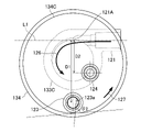
- the blood flowing in from the inflow port 121 formed on the side surface of the air trap chamber 100 forms a swirling blood flow 126 along the inner wall of the air trap chamber 100 in the first direction.
- the swirl direction of the drug solution flow 127 of the drug solution introduced from the port 123 having the liquid guide tube 123B is the first direction, coinciding with the direction of the blood flow 126 .
- turbulence is less likely to occur than when the liquid medicine drops vertically from the liquid guide tube 123B or when the liquid medicine is introduced so as to swirl in the direction opposite to the blood flow 126 .
- the medicinal solution and blood can be mixed quickly and uniformly, and the generation of air bubbles and entrainment of the generated air bubbles can be prevented.
- the blood flow 126 turns counterclockwise.
- the side wall is cut so as to include the farthest counterclockwise position from the inflow port 121 in the liquid guide tube 123B, and the side opening 123a is formed. can be formed.
- the side opening 123a can be formed by notching the side wall so as to include the position of the liquid introducing tube 123B that is the furthest clockwise from the inflow port 121 .
- the angle ⁇ 2 formed by the opening surface of the side opening 123a and the inner wall surface of the chamber body 101 is preferably smaller than 90°.
- ⁇ 2 is an angle formed by a tangent line to the inner wall surface at the position where the extension line of the opening surface intersects the inner wall surface of the chamber main body 101 and the extension line of the opening surface.
- the side opening 123a of the port 123 for introducing the drug solution is preferably formed above the inflow port 121 for blood.
- the side opening 123a can be located in the first space, which is the combination of the large diameter portion 111 and the intermediate portion 112, and the inflow port 121 can be located in the second space, which is the small diameter portion 113.
- simulations were conducted to compare the mixing of replacement fluid between a chamber having a large-diameter first space and a chamber having a constant diameter. It was found that a layer of the replacement fluid was more easily formed on the top when the replacement fluid was supplied.
- the replacement fluid layer is not limited to a layer containing no blood at all, and includes a layer with a low blood concentration.
- the inclination angle of the inner surface of the intermediate portion 112 is preferably 60° or less. ° or less is more preferable.
- the speed at which the drug solution introduced from the port 123 collides with the blood flowing from the inflow port 121 can be reduced, so that a layer of replacement fluid is likely to be formed on the blood layer.
- the inclination angle is preferably 20° or more, more preferably 30° or more.
- FIG. 12 shows an air trap chamber above the inflow port 121 that has a large-diameter portion that can store blood and that can be used for single-needle dialysis.
- the liquid medicine is discharged so as to swirl along the swirling direction of the blood flow 126, thereby smoothly mixing the liquid medicine and the blood. It can be carried out.
- the port 123 for introducing a liquid such as a chemical solution is preferably positioned on the front side of the top plate portion 134C when used, but can be formed at any position on the top plate portion 134C.
- the port 123 for introducing a liquid such as a chemical solution is formed at a position close to the inflow port 121 on the top plate portion (on the back side of the top plate portion when used), although the handling of the chemical solution introduction line is reduced. You may Regardless of the position where the port 123 is formed, it is preferable to form the side opening 123a so that the swirling direction of the blood flowing in from the inflow port 121 and the swirling direction of the liquid flowing in from the port 123 are the same.
- the port for introducing the chemical solution can be formed on the side surface of the chamber main body 101 in the same manner as the inflow port 121, although the handling of the chemical solution introduction line is reduced. Also when the port for introducing the liquid medicine is formed on the side surface of the chamber main body 101, it is preferable that the swirling direction of the blood flow matches the swirling direction of the liquid medicine flow. Moreover, it is preferable to form the drug introduction port above the blood inflow port 121 .
- the port 123 for introducing the liquid medicine is formed in the top plate portion 134C
- its position is not particularly limited.
- the distance D1 between the port 123 for introducing the chemical solution and the axis L1 of the inflow port 121 is the same as the port 124 for pressure measurement and the inflow port 121.
- the chemical solution introduction port 123 and the pressure measurement port 124 are arranged in the direction in which the inflow port 121 extends.
- the port 123 for introducing the chemical solution is located closer to the front than the port 124 for pressure measurement, etc. ing.
- the distance between the inflow port 121 and the center of the top plate portion 134C is smaller than the distance between the chemical solution introduction port 123 and the center of the top plate portion 134C.
- 121 is provided so as to be located on the opposite side across the center of the top plate portion 134C.
- the projection direction of the inflow port 121 is set to be substantially parallel to the wall surface of the dialysis monitoring device 400 so that the inflow side line 203 does not interfere with the dialysis monitoring device 400.
- the port 123 farther from the axis L1 of the inflow port 121 will be closer to the front than the port 124 closer to it. Therefore, operations such as supplying the chemical solution to the port 123 are facilitated, and operability is improved.
- the direction connecting the connection position 121A of the inflow port 121 and the center of the port 123 is preferably ⁇ 45 with respect to the direction connecting the connection position 121A of the inflow port 121 and the center of the top plate portion 134C.
- the port 123 is preferably formed at the outer edge of the top plate portion 134C so as to be within the range of about ⁇ 15°, more preferably about ⁇ 15°.
- a port 124 to which a pressure measurement line or the like can be connected is preferably formed between the inflow ports 121 and 123 and at a position shifted in the direction in which the inflow port 121 protrudes from the line connecting the inflow ports 121 and 123. .
- the position of the transducer connecting the pressure measurement line in the dialysis monitoring device 400 is generally on the opposite side of the pump because it is advantageous for downsizing the dialysis monitoring device 400 .
- the port 124 is connected to the pump.
- the pressure measurement line can be connected to the dialysis monitoring device 400 more easily.
- a pressure measurement line can be connected to the port 124, but other lines such as a liquid level adjustment line can also be connected.
- FIG. 12 shows an example in which the top plate portion 134C is formed with a port 123 having a liquid guide tube 123B for introducing a chemical solution and a port 124 without a liquid guide tube. A configuration in which other ports are formed is also possible. Also, in the case of a dialysis monitoring device in which the pump is provided on the right side and the blood purifier is arranged on the left side, an air trap chamber in which each port is mirror-symmetrical can be used.
- An air trap chamber having a large diameter portion capable of retaining blood above the inflow port can be used in single-needle dialysis, but can also be used in normal double-needle dialysis.
- the air trap chamber of the present disclosure has excellent functionality and can be used for blood circuits for dialysis and the like.
Abstract
This air trap chamber comprises a cylindrical chamber body having a blood inflow port (121) and outflow port (122). The chamber body has a large-diameter part (111), a small-diameter part (113) that has a smaller diameter than the large-diameter part (111) and that is provided on the outflow port (122) side, and an intermediate part (112) that is provided between the large-diameter part (111) and the small-diameter part (113) and that has a diameter that gradually changes. The inflow port (121) is provided, on the side surface of the intermediate part (112)-side end part of the small-diameter part (113), so as to extend in a direction tangential to the circumference of the small-diameter part (113).
Description
本開示は、エアトラップチャンバに関する。
The present disclosure relates to air trap chambers.
腎機能が低下した患者に対し、血液を抜き出し浄化して戻す人工透析が行われている。人工透析のための体外循環回路には、血液から気泡を除去するためのエアトラップチャンバが設けられている。エアトラップチャンバは、下端部にフィルタが設けられた筒状であり、上端部の流入口から流入させた血液は、フィルタを通って下端の流出口から流出する。エアトラップチャンバ内に一定量の血液をためて血液層を形成することにより、血液層中の気泡を上側の空気層へ排出できる。
Artificial dialysis, in which the blood is extracted, purified, and returned, is performed for patients with decreased renal function. An extracorporeal circuit for artificial dialysis is provided with an air trap chamber for removing air bubbles from the blood. The air trap chamber has a cylindrical shape with a filter provided at the lower end, and the blood flowed in from the inlet at the upper end passes through the filter and flows out from the outlet at the lower end. By accumulating a certain amount of blood in the air trap chamber to form a blood layer, air bubbles in the blood layer can be discharged to the upper air layer.
通常の人工透析は、2カ所に穿刺を行い、脱血と返血の2つのルートを確保して行われる。しかし、シャントの状態等により穿刺が1カ所にしかできない場合がある。このような場合には、シングルニードル透析法が用いられる。シングルニードル透析法の場合には、分岐を有する穿刺針に体外循環回路の脱血側のラインと返血側のラインとが接続される。返血側のラインを閉じた状態で脱血及び浄化を行い、所定量の脱血及び浄化が終わると脱血側のラインを閉じて返血側のラインから浄化した血液が戻される。脱血と返血の動作は数秒ごとに繰り返される。
Normal artificial dialysis is performed by puncturing in two places and securing two routes for blood withdrawal and blood return. However, depending on the state of the shunt, etc., there are cases where only one puncture is possible. In such cases, single-needle dialysis is used. In the case of the single-needle dialysis method, a branched puncture needle is connected to a blood removal side line and a blood return side line of an extracorporeal circulation circuit. Blood removal and purification are performed with the blood return line closed, and when a predetermined amount of blood has been removed and purified, the blood removal line is closed and the purified blood is returned from the blood return line. The action of blood removal and blood return is repeated every few seconds.
通常の2カ所に穿刺を行う体外循環回路と同様に、シングルニードル透析法用の体外循環回路にもエアトラップチャンバが設けられる。シングルニードル透析法の場合、脱血中は返血されないためエアトラップチャンバに血液が溜まり続けることになる。このため、シングルニードル透析法用の体外循環回路には、通常の血液透析回路よりも径が太く、内容量が大きいエアトラップチャンバが用いられる(例えば、特許文献1を参照。)。
An air trap chamber is also provided in the extracorporeal circulation circuit for single-needle dialysis, just like an ordinary extracorporeal circulation circuit that performs punctures at two locations. In the case of the single needle dialysis method, the air trap chamber is continuously filled with blood because blood is not returned during blood removal. For this reason, an extracorporeal circulation circuit for single-needle dialysis uses an air trap chamber with a larger diameter and larger internal capacity than a normal hemodialysis circuit (see, for example, Patent Document 1).
透析監視装置は、通常のダブルニードル透析法だけでなく、シングルニードル透析法にも対応できるようにすることが求められている。このため、透析監視装置には、ダブルニードル透析法用のエアトラップチャンバを固定するホルダと、シングルニードル透析法用の径が太いエアトラップチャンバを固定するホルダとが別々に設けられており、透析監視装置を大型化する要因となっている。
Dialysis monitoring devices are required to be able to support not only the usual double-needle dialysis method, but also the single-needle dialysis method. For this reason, the dialysis monitoring device is provided with a separate holder for fixing the air trap chamber for the double-needle dialysis method and a holder for fixing the large-diameter air trap chamber for the single-needle dialysis method. This is a factor in increasing the size of the monitoring device.
また、シングルニードル透析法の場合、ポンプが動作して血液浄化器で浄化した血液をチャンバに貯留し、貯留完了後、ポンプが止まり、チャンバ上部よりエアーが送りだされ、貯留された血液が患者側へ戻り、液面が液面センサ付近まで下がるとエアーが止まり、再度貯留動作へと移行する。このような動作が繰り返されることで、透析施術が行われるが、液面が上下する変動が周期的に繰り返されるため血液入口から流入する血液と液面とが衝突した際に泡立ちが生じたり、溶血が生じたりするおそれがある。
In the case of single-needle dialysis, the pump operates to store the blood purified by the blood purifier in the chamber. After the storage is completed, the pump stops, air is sent out from the upper part of the chamber, and the stored blood is delivered to the patient. When the liquid level drops to the vicinity of the liquid level sensor, the air stops and the storage operation resumes. Dialysis treatment is performed by repeating such an operation, but the fluctuation of the liquid level is repeated periodically. Hemolysis may occur.
通常のダブルニードル透析法においても、シングルニードル透析法においても、静脈側において水分の補充をしたり、薬剤の投与を行ったりする場合がある。補液や他の薬液をエアトラップチャンバにおいて血液と混合する際に、薬液が血液面と衝突して気泡が生じ、気泡を巻き込んでしまうという問題がある。また、混合された薬液は血液と速やかに均一に混ざり合うことが好ましいが、エアトラップチャンバ内において、血液と薬液とが迅速に混ざり合わないという問題も生じ得る。
In both the normal double-needle dialysis method and the single-needle dialysis method, fluids may be replenished and drugs may be administered on the intravenous side. There is a problem that when the replacement fluid or other medical fluid is mixed with the blood in the air trap chamber, the medical fluid collides with the blood surface to generate air bubbles, which entrain the air bubbles. Moreover, although it is preferable that the mixed liquid medicine mixes with the blood quickly and uniformly, there may arise a problem that the blood and the liquid medicine do not mix quickly in the air trap chamber.
さらに、浄化した血液を一旦貯留するシングルニードル透析法用のチャンバは、大きくなるため、ポートの配置によってはラインチューブの取り回しに支障をきたしたり、薬液の投与操作の際に邪魔になったりするという問題もある。
Furthermore, because the chamber for single-needle dialysis, which temporarily stores the purified blood, is large, depending on the port arrangement, it may interfere with the handling of the line tube or interfere with the administration of the drug solution. There is also a problem.
本開示の課題は、これらの問題の少なくとも1つを解決して、機能性に優れたエアトラップチャンバを実現できるようにすることである。
An object of the present disclosure is to solve at least one of these problems and realize an air trap chamber with excellent functionality.
本開示のエアトラップチャンバの第1の態様は、血液の流入ポートと、流出ポートとを有する筒状のチャンバ本体を備え、チャンバ本体は、大径部と、大径部よりも径が小さく、流出ポート側に設けられた小径部と、大径部と小径部との間に設けられ、径が次第に変化する中間部とを有し、流入ポートは、小径部の中間部側の端部の側面に、小径部の円周の接線方向に延びるように設けられている。
A first aspect of the air trap chamber of the present disclosure comprises a tubular chamber body having a blood inflow port and a blood outflow port, the chamber body having a large diameter portion and a smaller diameter than the large diameter portion, It has a small diameter portion provided on the outflow port side, and an intermediate portion provided between the large diameter portion and the small diameter portion and having a gradually changing diameter, and the inflow port is located at the end of the intermediate portion side of the small diameter portion. It is provided on the side surface so as to extend in the tangential direction of the circumference of the small diameter portion.
エアトラップチャンバの第1の態様は、チャンバ本体が大径部と、大径部よりも径が小さく、流出ポート側に設けられた小径部とを有している。このため、チャンバの容量を十分に確保することができる。さらに、流入ポートが小径部の円周の接線方向に延びるように設けられているため、血液と液面との衝突が避けられ、血液が泡だったり溶血したりしにくくできる。また、流入ポートから流入した血液はチャンバ側面に沿って流れ、回転流を引き起こす。流入ポートが小径部にあるため、液面が上下しても、回転流が生じている状態を維持しやすく、また、液面の上下動と相まって、チャンバ内全体を効率的に攪拌することができる。
In a first aspect of the air trap chamber, the chamber body has a large diameter portion and a small diameter portion smaller in diameter than the large diameter portion and provided on the outflow port side. Therefore, a sufficient capacity of the chamber can be secured. Furthermore, since the inflow port is provided so as to extend tangentially to the circumference of the small-diameter portion, collision between the blood and the liquid surface is avoided, and the blood is less likely to bubble or hemolyze. In addition, the blood that has flowed in from the inflow port flows along the side of the chamber, causing a rotating flow. Since the inflow port is located at the small diameter part, even if the liquid level rises and falls, it is easy to maintain the state in which the rotating flow is generated. can.
エアトラップチャンバの第2の態様は、血液の流入ポートと、流出ポートとを有する筒状のチャンバ本体を備え、チャンバ本体は、大径部と、大径部よりも径が小さく、流出ポート側に設けられた小径と、大径部と小径部との間に設けられ、径が次第に変化する中間部とを有し、大径部の内径は、小径部の内径の1.5倍以上、3倍以下であり、大径部の長さは、小径部の長さの20%以上、70%以下である。
A second aspect of the air trap chamber comprises a cylindrical chamber body having a blood inflow port and an outflow port, the chamber body having a large diameter portion and a smaller diameter than the large diameter portion, and the outflow port side. and an intermediate portion provided between the large diameter portion and the small diameter portion, the diameter of which gradually changes, and the inner diameter of the large diameter portion is 1.5 times or more the inner diameter of the small diameter portion, 3 times or less, and the length of the large diameter portion is 20% or more and 70% or less of the length of the small diameter portion.
エアトラップチャンバの第2の態様は、大径部の内径を、小径部の内径の1.5倍以上、3倍以下、大径部の長さを、小径部の長さの20%以上、70%以下とすることにより、チャンバの容量を確保しつつ、小径部の径を細くすると共に、チャンバの全長を短くすることができる。これにより、透析監視装置に容易に取り付けることができる。
In a second aspect of the air trap chamber, the inner diameter of the large diameter portion is 1.5 times or more and 3 times or less the inner diameter of the small diameter portion, the length of the large diameter portion is 20% or more of the length of the small diameter portion, By making it 70% or less, it is possible to reduce the diameter of the small-diameter portion and shorten the total length of the chamber while ensuring the capacity of the chamber. This allows easy attachment to the dialysis monitor.
エアトラップチャンバの第3の態様は、血液の流入ポートと、流出ポートとを有する筒状のチャンバ本体を備え、チャンバ本体は、大径部と、大径部よりも径が小さく、流出ポート側に設けられた小径と、大径部と小径部との間に設けられ、径が次第に変化する中間部とを有し、大径部の容積は、チャンバ本体の容積の30%以上、70%以下である。
A third aspect of the air trap chamber comprises a tubular chamber body having a blood inflow port and an outflow port, the chamber body having a large diameter portion and a smaller diameter than the large diameter portion, and the outflow port side. and an intermediate portion provided between the large-diameter portion and the small-diameter portion, the diameter of which gradually changes, and the volume of the large-diameter portion is 30% or more and 70% of the volume of the chamber body. It is below.
エアトラップチャンバの第3の態様において、チャンバ本体が大径部と、大径部よりも径が小さく、流出ポート側に設けられた小径部とを有し、大径部の容積は、チャンバ本体の容積の30%以上、70%以下である。このため、チャンバの容量を確保しつつ、小径部の径を細くすると共に、チャンバの全長を短くすることができ、透析監視装置に容易に取り付けることができる。
In a third aspect of the air trap chamber, the chamber body has a large diameter portion and a small diameter portion smaller in diameter than the large diameter portion and provided on the outflow port side, the volume of the large diameter portion being equal to the volume of the chamber body 30% or more and 70% or less of the volume of Therefore, it is possible to reduce the diameter of the small-diameter portion and shorten the total length of the chamber while ensuring the capacity of the chamber, and to easily attach the chamber to the dialysis monitoring device.
本開示のエアトラップチャンバにおいて、大径部は導液ポートを有し、流入ポートが小径部の上方側に位置する。小径部と大径部は中間部を介して離れているため、大径部から流入した補液が液面と衝突することにより生じる気泡は中間部により下方には到達しにくい。また、流入ポートが中間部にある場合、血液流が中間部内面に沿って駆け上がるような流れとなり、上下動する液面と相まって液面を波出せてしまう可能性があるが、流入ポートが小径部にあることで、このような事態の発生を低減できる。また、流入ポートが小径部の上方側に位置することで、導液ポートから流入する薬剤や補液が血液流と混ざりやすくなり、混合液を患者に戻しやすくすることができる。
In the air trap chamber of the present disclosure, the large diameter portion has a liquid introduction port, and the inflow port is positioned above the small diameter portion. Since the small-diameter portion and the large-diameter portion are separated from each other through the intermediate portion, the intermediate portion makes it difficult for the air bubbles generated by the replacement fluid flowing from the large-diameter portion to collide with the liquid surface to reach downward. In addition, if the inflow port is located in the middle part, the blood flow becomes a flow that runs up along the inner surface of the middle part, and there is a possibility that the liquid surface will ripple out due to the upward and downward movement of the liquid surface. Occurrence of such a situation can be reduced by being in the small diameter portion. In addition, since the inflow port is positioned above the small-diameter portion, the medicine and replacement fluid flowing in from the liquid introduction port can be easily mixed with the blood flow, and the mixed fluid can be easily returned to the patient.
本開示のエアトラップチャンバにおいて、チャンバ本体は、小径部の少なくとも一部を構成する第1部材と、大径部、中間部及び流入ポートを含む第2部材とを有し、第1部材は、第2部材よりも可撓性が高くてもよい。このような構成とすることにより、上下動する液面が接触しやすい大径部、中間部及び小径部上方側の内面を段差がない滑らかな形状とすることができ、血栓が生じる事態を低減することができる。また、第1部材が第2部材よりも可撓性が高いことで、プライミングの際に鉗子等で叩いて気泡を除去する際に、損傷が起きにくくすることができる。なお、小径部を被取付部とした場合、透析監視装置へ取り付けを行う小径部の柔軟性を確保しつつ、チャンバ全体の強度を確保して、チャンバ内部に血液を貯留した場合にも変形が生じにくくすることができる。
In the air trap chamber of the present disclosure, the chamber body has a first member that constitutes at least part of the small-diameter portion, and a second member that includes the large-diameter portion, the intermediate portion, and the inflow port, the first member comprising: It may be more flexible than the second member. With such a configuration, the inner surfaces of the large-diameter portion, the middle portion, and the upper side of the small-diameter portion, which are likely to come into contact with the liquid surface that moves up and down, can be formed into a smooth shape without steps, thereby reducing the occurrence of thrombi. can do. In addition, since the first member is more flexible than the second member, it is possible to prevent damage from occurring when air bubbles are removed by tapping with forceps or the like during priming. In addition, when the small diameter portion is used as the attachment portion, the flexibility of the small diameter portion to be attached to the dialysis monitoring device is secured, and the strength of the entire chamber is secured, so that even if blood is accumulated inside the chamber, deformation will not occur. can be made less likely to occur.
本開示のエアトラップチャンバにおいて、チャンバ本体は、中間部及び大径部の少なくとも一部に亘って外側面に形成されたリブを有していてもよい。このような構成とすることにより、大径部に血液が貯留された状態でも、大径部及び中間部の変形を小さくすることができる。
In the air trap chamber of the present disclosure, the chamber body may have ribs formed on the outer surface over at least part of the intermediate portion and the large diameter portion. With such a configuration, deformation of the large-diameter portion and the intermediate portion can be reduced even when blood is stored in the large-diameter portion.
本開示のエアトラップチャンバの第4の態様は、血液の流入ポートと、流出ポートと、導液ポートとを有する筒状のチャンバ本体を備え、チャンバ本体は、第一空間と、第一空間よりも流出ポート側に設けられた第二空間とを有し、第一空間は第二空間より大径に形成され、導液ポートにおける流入口は第一空間内に位置し、血液の流入ポートにおける流入口は第二空間内に位置し、流入ポートから流入する血液及び導液ポートから流入する液体は、チャンバ本体の内壁面に沿って第1の方向に旋回するように導かれる。
A fourth aspect of the air trap chamber of the present disclosure includes a tubular chamber body having a blood inflow port, an outflow port, and a liquid introduction port, wherein the chamber body includes a first space and a and a second space provided on the outflow port side, the first space is formed to have a larger diameter than the second space, the inflow port of the liquid introduction port is located in the first space, and the inflow port of the blood The inflow port is located in the second space, and the blood flowing in from the inflow port and the liquid flowing in from the liquid introduction port are guided along the inner wall surface of the chamber main body so as to swirl in the first direction.
エアトラップチャンバの第4の態様において、流入ポートから流入する血液及び導液ポートから流入する液体は、チャンバ本体の内壁面に沿って第1の方向に旋回するように導かれる。このため、チャンバ本体内において乱流が発生しにくく、血液と液体とが迅速に均一に混合されると共に気泡の発生や、発生した気泡の巻き込みを生じにくくすることができる。また、導液ポートにおける流入口は第一空間内に位置し、血液の流入ポートにおける流入口は第二空間内に位置しているため、血液の層の上に導液ポートから導入した液体の層が形成されやすく、血液が直接空気と接触しないような状態を容易に作り出すことができる。
In the fourth aspect of the air trap chamber, blood flowing in from the inflow port and liquid flowing in from the liquid introduction port are guided along the inner wall surface of the chamber main body so as to swirl in the first direction. Therefore, turbulence is less likely to occur in the chamber main body, blood and liquid are rapidly and uniformly mixed, and air bubbles are less likely to be generated and entrapment of generated air bubbles to be less likely to occur. In addition, since the inflow port of the liquid introduction port is located in the first space and the inflow port of the blood inflow port is located in the second space, the liquid introduced from the liquid introduction port is placed on the blood layer. A layer is easily formed, and a condition can be easily created in which the blood does not come into direct contact with the air.
本開示のエアトラップチャンバの第5の態様は、血液の流入ポートと、流出ポートと、導液ポートとを有する筒状のチャンバ本体を備え、流入ポートは、チャンバ本体の側面に、チャンバ本体の円周の接線方向に延びるように設けられ、導液ポートは、チャンバ本体の天板部から、チャンバ本体内へ突出した、底面が閉じられ側面開口を有する導液筒を有し、流入ポートから流入する血液及び導液ポートから流入する液体は、チャンバ本体の内壁面に沿って第1の方向に旋回するように導かれる。
A fifth aspect of the air trap chamber of the present disclosure includes a tubular chamber body having a blood inflow port, an outflow port, and a liquid introduction port, and the inflow port is located on the side surface of the chamber body. The liquid introduction port is provided so as to extend in the tangential direction of the circumference, and the liquid introduction port has a liquid introduction cylinder with a closed bottom surface and a side opening that protrudes into the chamber main body from the top plate portion of the chamber main body. Incoming blood and liquid entering from the liquid introduction port are guided to swirl in a first direction along the inner wall surface of the chamber body.
エアトラップチャンバの第5の態様において、導液筒に設けられた側面開口は、血液流の下流側に開口しているので、導液ポートから導入された液体は、血液流と同じ方向に流れる。このため、チャンバ本体内において乱流が発生しにくく、血液と液体とが迅速に均一に混合されると共に気泡の発生や、発生した気泡の巻き込みを生じにくくすることができる。
In the fifth aspect of the air trap chamber, the side opening provided in the liquid guide tube is open to the downstream side of the blood flow, so the liquid introduced from the liquid guide port flows in the same direction as the blood flow. . Therefore, turbulence is less likely to occur in the chamber main body, blood and liquid are rapidly and uniformly mixed, and air bubbles are less likely to be generated and entrapment of generated air bubbles to be less likely to occur.
エアトラップチャンバの第5の態様において、側面開口とチャンバ本体の内壁面とのなす角は、90°よりも小さくすることができる。このような構成とすることにより、導液ポートから流入した液体が、チャンバ本体の内壁面によりスムーズに導かれ、旋回する流れを形成しやすくできる。
In the fifth aspect of the air trap chamber, the angle between the side opening and the inner wall surface of the chamber body can be less than 90°. With such a configuration, the liquid that has flowed in from the liquid introduction port can be smoothly guided by the inner wall surface of the chamber body, making it easier to form a swirling flow.
本開示のエアトラップチャンバの第6の態様は、血液の流入ポートと、流出ポートと、導液ポートと、圧力測定ポートとを有する筒状のチャンバ本体を備え、チャンバ本体は、大径部と、大径部よりも径が小さく、流出ポート側に設けられた小径部と、大径部と小径部との間に設けられ、径が次第に変化する中間部とを有し、流入ポートは、小径部の円周の接線方向に沿って突出して設けられ、導液ポート及び圧力測定ポートは、チャンバ本体の天板部に形成され、天板部を平面視した場合に、導液ポートと流入ポートの軸線との距離は、圧力測定ポートと流入ポートの軸線との距離よりも大きく、圧力測定ポートは、天面における流入ポートと導液ポートとの間で且つ流入ポートと導液ポートとを結ぶ線から流入ポートが突出する方向にずれた位置に形成されている。
A sixth aspect of the air trap chamber of the present disclosure includes a tubular chamber body having a blood inflow port, an outflow port, a liquid introduction port, and a pressure measurement port, wherein the chamber body includes a large diameter portion and a pressure measurement port. , a small diameter portion provided on the outflow port side and having a smaller diameter than the large diameter portion; and an intermediate portion provided between the large diameter portion and the small diameter portion and having a diameter that gradually changes, The liquid introduction port and the pressure measurement port are formed on the top plate of the chamber body, and when the top plate is viewed from above, the liquid introduction port and the inflow The distance from the axis of the port is greater than the distance between the pressure measurement port and the axis of the inflow port, and the pressure measurement port is located between the inflow port and the liquid introduction port on the top surface and between the inflow port and the liquid introduction port. It is formed at a position shifted in the direction in which the inflow port protrudes from the connecting line.
エアトラップチャンバの第6の態様において、天板部を平面視した場合に、導液ポートと流入ポートの軸線との距離は、圧力測定ポートと流入ポートの軸線との距離よりも大きい。このため、血液浄化器と繋がるラインが邪魔にならないように、流入ポートを透析監視装置の奥側に配置すると、導液ポートが圧力測定ポートよりも手前側となる。このため、使用者は導液ポートを用いた薬液の投与操作が容易になる。また、圧力測定ポートは、天面における流入ポートと導液ポートとの間で且つ流入ポートと導液ポートとを結ぶ線から流入ポートが突出する方向にずれた位置に設けられているので、圧力測定ポートに取り付けられる圧力測定用ラインを透析監視装置に接続しやすく、圧力測定用ラインの取り回しが容易になる。
In the sixth aspect of the air trap chamber, the distance between the liquid introduction port and the axis of the inflow port is greater than the distance between the pressure measurement port and the axis of the inflow port when the top plate is viewed from above. Therefore, if the inflow port is arranged on the back side of the dialysis monitoring device so that the line connected to the blood purifier does not get in the way, the liquid introduction port will be on the front side of the pressure measurement port. Therefore, the user can easily administer the liquid medicine using the liquid introduction port. In addition, the pressure measurement port is provided at a position between the inflow port and the liquid introduction port on the top surface and at a position shifted in the direction in which the inflow port projects from the line connecting the inflow port and the liquid introduction port. The pressure measurement line attached to the measurement port can be easily connected to the dialysis monitoring device, and the pressure measurement line can be easily routed.
本開示のエアトラップチャンバによれば、透析監視装置を複雑化することなくシングルニードル透析法に対応したり、薬液の導入時の泡立ち等を低減したり、血液と薬液との混合を促進したりすることの少なくとも1つを実現できる。
According to the air trap chamber of the present disclosure, it is possible to support single-needle dialysis without complicating the dialysis monitoring device, reduce foaming when introducing the drug solution, and promote mixing of the blood and the drug solution. at least one of the following:
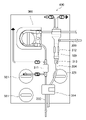
本開示のエアトラップチャンバ100は、シングルニードル透析法用の血液回路に用いることができるエアトラップチャンバであり、例えば、図1に示すような透析監視装置400に取り付けられる。エアトラップチャンバ100は、透析監視装置400の側面に設けられたホルダ312及び313により透析監視装置400上に保持される。ホルダ312には、エアトラップチャンバ100を側方から挟み込んで保持している。また、液面レベルセンサを有しており、エアトラップチャンバ100内の液面レベルが低くなりすぎないように監視することができる。ホルダ313は、エアトラップチャンバ100の下端部を支えており、エアトラップチャンバ100と液面レベルセンサとの相対位置を一定にし、液面監視が正しく行われるようにしている。また、透析監視装置400のエアトラップチャンバ100が取り付けられる部分の周囲には、脱血側ライン202が取り付けられるポンプ300、ライン202中を流れる血液の成分分析を行う成分センサ311、ライン202及び204の開閉を行うクランプ部314、透析液等の供給を行ったり、廃液を流したりするための複数のポート321等が配置されている。ポンプ300を停止させることにより脱血側のライン202を十分に閉止できる場合には、クランプ部314は返血側のライン202だけを開閉する構成としてもよい。また、クランプ部314にライン中の気泡を検出したり、漏血を検出したりするセンサを設けることもできる。
The air trap chamber 100 of the present disclosure is an air trap chamber that can be used in a blood circuit for single-needle dialysis, and is attached to, for example, a dialysis monitor 400 as shown in FIG. Air trap chamber 100 is held on dialysis monitor 400 by holders 312 and 313 provided on the sides of dialysis monitor 400 . The holder 312 sandwiches and holds the air trap chamber 100 from the side. Moreover, it has a liquid level sensor and can monitor the liquid level in the air trap chamber 100 so that it does not become too low. The holder 313 supports the lower end of the air trap chamber 100 to keep the relative positions of the air trap chamber 100 and the liquid level sensor constant so that the liquid level can be properly monitored. In addition, around the portion of the dialysis monitoring device 400 to which the air trap chamber 100 is attached, there are a pump 300 to which a blood removal side line 202 is attached, a component sensor 311 for analyzing components of the blood flowing through the line 202, lines 202 and 204. A clamp portion 314 for opening and closing the dialysate, a plurality of ports 321 for supplying dialysate and the like, and for draining waste fluid are arranged. If the line 202 on the blood removal side can be sufficiently closed by stopping the pump 300, the clamp section 314 may be configured to open and close only the line 202 on the blood return side. Further, a sensor for detecting air bubbles in the line or detecting blood leakage may be provided in the clamp section 314 .
シングルニードル透析法の場合、クランプ部314により返血側のライン204が閉じられた状態でポンプ300により脱血を行い、人工透析器に血液を送る。人工透析器により浄化された血液は、エアトラップチャンバ100に流入し、貯留される。次に、脱血側のライン202が閉じられ、返血側のライン204が開けられると、エアトラップチャンバ100内の浄化された血液は、患者の体に戻される。流速にもよるがこの動作が数秒から数十秒ごとに繰り返される。
In the case of the single-needle dialysis method, blood is removed by the pump 300 while the line 204 on the blood return side is closed by the clamp part 314, and the blood is sent to the artificial dialyzer. Blood purified by the artificial dialyzer flows into the air trap chamber 100 and is stored therein. Next, when the blood removal side line 202 is closed and the blood return side line 204 is opened, the purified blood in the air trap chamber 100 is returned to the patient's body. Depending on the flow velocity, this operation is repeated every few seconds to several tens of seconds.
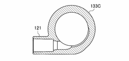
エアトラップチャンバ100は、図2~図10に示すように、筒状のチャンバ本体101とその内部に設けられたトラップフィルタ141とを有している。チャンバ本体101は、第1部材132と、第1部材132の下端に連結された下端キャップ部131と、上端に連結された第2部材133及び上端キャップ部134とにより構成されている。第2部材133は、第1部材132が連結される小径部分133Cと、上端キャップ部134が連結される大径部分133Aとを有し、大径部分133Aと小径部分133Cとの間には、次第に縮径する縮径部分133Bが設けられている。
As shown in FIGS. 2 to 10, the air trap chamber 100 has a cylindrical chamber main body 101 and a trap filter 141 provided therein. The chamber body 101 is composed of a first member 132, a lower end cap portion 131 connected to the lower end of the first member 132, and a second member 133 and an upper end cap portion 134 connected to the upper end. The second member 133 has a small diameter portion 133C to which the first member 132 is connected, and a large diameter portion 133A to which the upper end cap portion 134 is connected. A diameter-reduced portion 133B that gradually reduces in diameter is provided.
小径部分133Cには、流入側のライン203が接続され血液が流入する流入ポート121が設けられている。上端キャップ部134は、第2部材133に外嵌する連結部134Aと、側壁部134Bと、天板部134Cとを有しており、天板部134Cには、ポート123及び124が設けられている。下端キャップ部131は、下端が返血側のライン204を接続する流出ポート122となっており、下端キャップ部131の内部にはトラップフィルタ141が固定されている。流入ポート121からチャンバ内に流入した血液は、トラップフィルタ141を通過して流出ポート122から流出する。
The small diameter portion 133C is provided with an inflow port 121 to which the line 203 on the inflow side is connected and into which blood flows. The upper end cap portion 134 has a connecting portion 134A fitted onto the second member 133, a side wall portion 134B, and a top plate portion 134C. there is The lower end of the lower end cap portion 131 serves as an outflow port 122 that connects the line 204 on the blood return side, and a trap filter 141 is fixed inside the lower end cap portion 131 . The blood that has flowed into the chamber from the inflow port 121 passes through the trap filter 141 and flows out from the outflow port 122 .
第2部材133の大径部分133Aと上端キャップ部134とにより大径部111が形成され、第2部材133の小径部分133C、第1部材132及び下端キャップ部131の上部により小径部113が形成され、第2部材133の縮径部分133Bにより中間部112が形成される。なお、本開示において大径部111及び中間部112を第一空間とし、第一空間よりも流出ポート側の小径部113を第二空間とする。
A large diameter portion 111 is formed by the large diameter portion 133A of the second member 133 and the upper end cap portion 134, and a small diameter portion 113 is formed by the small diameter portion 133C of the second member 133, the first member 132 and the upper portion of the lower end cap portion 131. The intermediate portion 112 is formed by the reduced diameter portion 133B of the second member 133. As shown in FIG. In the present disclosure, the large-diameter portion 111 and the intermediate portion 112 are defined as a first space, and the small-diameter portion 113 closer to the outflow port than the first space is defined as a second space.
小径部113の外径及び内径は、2カ所に穿刺をして脱血と返血とを同時に行う通常の血液透析法に用いる血液回路のエアトラップチャンバの外径及び内径とほぼ等しい。透析監視装置400においては、エアトラップチャンバを挟み込むように液面レベルセンサが設けられたホルダ312に取り付けて、チャンバ内の液面の監視を行う。ホルダ312には、プライミング時の液面レベルを制御するための液面レベルセンサと、シングルニードル法においてエアトラップチャンバ内の液面レベルを監視するための液面レベルセンサとが設けられている。
The outer diameter and inner diameter of the small-diameter portion 113 are approximately equal to the outer diameter and inner diameter of an air trap chamber of a blood circuit used in a normal hemodialysis method in which two punctures are made to simultaneously remove and return blood. The dialysis monitoring device 400 is attached to a holder 312 provided with a liquid level sensor so as to sandwich the air trap chamber, and monitors the liquid level in the chamber. The holder 312 is provided with a liquid level sensor for controlling the liquid level during priming and a liquid level sensor for monitoring the liquid level in the air trap chamber in the single needle method.
一方、シングルニードル透析法の場合、脱血時に血液を貯留できるように、エアトラップチャンバに必要とされる容積は、通常の血液透析法の場合と比べて1.5倍~3倍程度となる。エアトラップチャンバ全体の内径及び外径を、通常のダブルニードルの血液透析法の場合と同じにすると、エアトラップチャンバの長さが非常に長くなってしまう。本実施形態のエアトラップチャンバ100は、小径部113よりも内径が大きい大径部111を有している。このため、エアトラップチャンバの長さを抑えつつ、容積を大きくすることができる。
On the other hand, in the case of single-needle dialysis, the volume required for the air trap chamber to retain blood during blood removal is about 1.5 to 3 times the volume required in normal hemodialysis. . If the inner and outer diameters of the entire air trap chamber were the same as in a conventional double-needle hemodialysis method, the length of the air trap chamber would be very long. The air trap chamber 100 of this embodiment has a large diameter portion 111 having an inner diameter larger than that of the small diameter portion 113 . Therefore, the volume of the air trap chamber can be increased while reducing the length of the air trap chamber.
大径部111の内径は、必要とするチャンバの容積に応じて設定できるが、長さを抑えつつ容積を大きくする観点から、小径部113の内径の好ましくは1.5倍以上、より好ましくは2.2倍以上である。また、大径部111の内径は、いびつな形状となり透析監視装置への取り付けが困難にならないようにする観点から、小径部113の内径の好ましくは3倍以下、より好ましくは2.8倍以下である。また、大径部111の長さは、必要とするチャンバの容積に応じて設定できるが、チャンバの全長を短くする観点から小径部113の長さの好ましくは70%以下、より好ましくは50%以下である。また、容積を確保する観点から小径部113の長さは好ましくは20%以上、より好ましくは25%以上である。
The inner diameter of the large diameter portion 111 can be set according to the required volume of the chamber, but from the viewpoint of increasing the volume while suppressing the length, it is preferably 1.5 times or more, more preferably 1.5 times the inner diameter of the small diameter portion 113. 2.2 times or more. In addition, the inner diameter of the large-diameter portion 111 is preferably 3 times or less, more preferably 2.8 times or less, the inner diameter of the small-diameter portion 113 from the viewpoint of preventing the distorted shape from making it difficult to attach to the dialysis monitoring device. is. The length of the large diameter portion 111 can be set according to the required volume of the chamber. It is below. Moreover, from the viewpoint of securing the volume, the length of the small diameter portion 113 is preferably 20% or more, more preferably 25% or more.
また、脱血時に必要な血液を貯留できるようにする観点から、大径部111の容積はチャンバ本体101の全容積の好ましくは30%以上、より好ましくは40%以上である。また、小径部113の部分を確保する観点から、大径部111の容積はチャンバ本体101の全容積の好ましくは70%以下、より好ましくは60%以下である。
In addition, from the viewpoint of storing the blood necessary for blood removal, the volume of the large diameter portion 111 is preferably 30% or more, more preferably 40% or more, of the total volume of the chamber main body 101 . From the viewpoint of securing the small diameter portion 113 , the volume of the large diameter portion 111 is preferably 70% or less, more preferably 60% or less, of the total volume of the chamber body 101 .
本実施形態のエアトラップチャンバ100において、流入ポート121は、小径部113の側面に、小径部113の円周の接線方向に沿って突出して設けられている。流入ポートをチャンバの上端に垂直方向に設けると、落下した血液が液面に衝突して泡だったり、溶血したりしやすくなる。また、小径部113の円周に垂直にポートを設けると、脈流となった血液がポートから勢いよく噴き出して反対側の壁面に衝突したり、壁面を伝わらずに垂直に落下したりするおそれがある。流入ポート121を円周の接線方向に伸ばすことにより、内壁面に沿わせてらせん状にチャンバ内を移動させることができ、泡立ちや溶血を生じにくくすることができる。
In the air trap chamber 100 of this embodiment, the inflow port 121 is provided on the side surface of the small diameter portion 113 so as to protrude along the tangential direction of the circumference of the small diameter portion 113 . If the inflow port is provided vertically at the upper end of the chamber, the falling blood is more likely to collide with the liquid surface and foam or hemolyze. In addition, if a port is provided perpendicularly to the circumference of the small-diameter portion 113, the pulsating blood may spurt out from the port and collide with the wall on the opposite side, or fall vertically without passing through the wall. There is By extending the inflow port 121 in the tangential direction of the circumference, it is possible to move the inside of the chamber spirally along the inner wall surface, and it is possible to prevent bubbling and hemolysis from occurring.
本実施形態においては、図6に示すように、小径部分133Cの内壁面における流入ポート121が接続された1/4周程度の部分においてわずかにRを大きくしている。このような構成とすることにより、溶血等をより生じにくくすることができる。但し、このようなRの大きい部分は必要に応じて設ければよく、設けなくてもよい。
In the present embodiment, as shown in FIG. 6, the radius R is slightly increased in the portion of the inner wall surface of the small-diameter portion 133C that is about 1/4 of the circumference where the inflow port 121 is connected. With such a configuration, it is possible to make hemolysis and the like less likely to occur. However, such a large R portion may be provided as needed, and may not be provided.
本実施形態のエアトラップチャンバ100においては、チャンバ内の液面が、脱血動作の終了時には、流入ポート121よりも上側の大径部111内に位置し、返血動作の終了時つまり脱血動作の開始時には、流入ポート121よりも下側の小径部113内に位置する。この際の液面とトラップフィルタ141の天面との間隔は1cm~3cm程度となる。
In the air trap chamber 100 of this embodiment, the liquid surface in the chamber is positioned within the large-diameter portion 111 above the inflow port 121 at the end of the blood removal operation, At the start of operation, it is located within the small diameter portion 113 below the inflow port 121 . At this time, the distance between the liquid surface and the top surface of the trap filter 141 is about 1 cm to 3 cm.
流入ポート121から流入した血液は、管壁に沿って旋回しながら小径部113に向かう。流入ポート121を、大径部分133Aや傾斜面となった縮径部分133Bに設けると、血流は傾斜角度が変化する部分を通過するため、その部分において管壁に沿う流れが損なわれ、中心に向かおうとする流れが生じる。これにより、空気を巻き込んで泡立ちが生じ、血栓の原因となる。また、流入ポート121を縮径部分133Bに設けると、縮径部分133Bの内面に沿って上方に駆け上がるような血液流が発生しやすくなる。このため、脱血及び返血により大きく上下動する液面との相乗効果により液面が波立ってしまうおそれがある。流入ポート121を小径部分133Cに設けることによりこのような事態を生じにくくできる。
The blood that has flowed in from the inflow port 121 heads toward the small diameter portion 113 while swirling along the tube wall. If the inflow port 121 is provided in the large-diameter portion 133A or the reduced-diameter portion 133B, which is an inclined surface, the blood flow passes through the portion where the angle of inclination changes. There is a current that tries to go to This entrains air and causes foaming, which causes thrombus. Further, when the inflow port 121 is provided in the diameter-reduced portion 133B, a blood flow that runs upward along the inner surface of the diameter-reduced portion 133B is likely to occur. For this reason, there is a possibility that the liquid surface will ripple due to the synergistic effect of the liquid surface that moves up and down significantly due to blood removal and blood return. By providing the inflow port 121 in the small diameter portion 133C, such a situation can be made difficult to occur.
側方から血液を流入させるエアトラップチャンバにおいては、チャンバ内全体が効率的に攪拌されるように血液がチャンバ側面に沿って回転流を生じさせることが好ましい。流入ポート121を小径部分133Cに設けることにより、脱血時及び返血時に液面が大きく上下しても、回転流を維持しやすい。また、脱血時及び返血時にチャンバ内の液面が上下する一方、流入ポート121からは上下方向と交差する方向に血液が流入するため、流入ポート121から流入した血液はチャンバ内全体を効率的に攪拌することができる。また、流入ポート121の上方に縮径部分133B及び大径部分133Aが存在するため、天板部134Cに設けられたポート123、124から導入される補液や薬剤と液面との衝突により生じる気泡は小径部分133Cに比較的到達しにくい一方、小径部分133Cの上方に流入ポート121が位置することで、補液や薬剤と血液とをより混合しやすくすることができる。
In an air trap chamber into which blood flows in from the side, it is preferable to cause a rotating flow of blood along the side of the chamber so that the entire chamber is efficiently stirred. By providing the inflow port 121 in the small-diameter portion 133C, it is easy to maintain a rotating flow even if the liquid surface rises and falls significantly during blood removal and blood return. In addition, while the liquid level in the chamber rises and falls during blood removal and blood return, blood flows in from the inflow port 121 in a direction that intersects the vertical direction. can be stirred vigorously. In addition, since the reduced diameter portion 133B and the large diameter portion 133A are present above the inflow port 121, bubbles are generated due to the collision between the replacement fluid and the medicine introduced from the ports 123 and 124 provided in the top plate portion 134C and the liquid surface. is relatively difficult to reach the small-diameter portion 133C, and the position of the inflow port 121 above the small-diameter portion 133C makes it easier to mix replacement fluids or drugs with blood.
流入ポート121を小径部分133Cに設けることにより、通常のダブルニードル法用のエアトラップチャンバとの互換性をさらに高くすることができる。図11は、本実施形態のエアトラップチャンバ100に代えて、ダブルニードル法用の体外循環回路を透析監視装置400に取り付けた例を示している。ダブルニードル法用のエアトラップチャンバ102と、本実施形態のエアトラップチャンバ100とは、流入ポート121よりも下側の部分の構成がほぼ同一となっている。このため、どちらのエアトラップチャンバもホルダ312及び313により保持することができる。また、エアトラップチャンバ内の液面レベルの監視も同じように行うことができる。なお、ダブルニードル法用のエアトラップチャンバ102は大径部111の内径は、小径部113の内径の1.5倍以上、3倍以下であり、大径部111の長さは、小径部113の長さの20%以上、70%以下とされている。このため、例示した透析監視装置400のホルダ312及び313は、本実施形態のエアトラップチャンバ100とダブルニードル法用のエアトラップチャンバの両方の取付が容易にできるように設計されている。但し、本実施形態のエアトラップチャンバ100は、両方のエアトラップチャンバが取り付けられるように設計された透析監視装置に限らず、シングルニードル法及びダブルニードル法の一方みに対応して設計された透析監視装置に取り付けることもできる。
By providing the inflow port 121 in the small diameter portion 133C, it is possible to further improve compatibility with the air trap chamber for the normal double needle method. FIG. 11 shows an example in which an extracorporeal circulation circuit for the double needle method is attached to a dialysis monitor 400 instead of the air trap chamber 100 of this embodiment. The air trap chamber 102 for the double-needle method and the air trap chamber 100 of the present embodiment have substantially the same structure below the inflow port 121 . Both air trap chambers can thus be held by holders 312 and 313 . Also, monitoring of the liquid level in the air trap chamber can be done in the same way. In addition, in the air trap chamber 102 for the double needle method, the inner diameter of the large diameter portion 111 is 1.5 times or more and 3 times or less than the inner diameter of the small diameter portion 113, and the length of the large diameter portion 111 is equal to that of the small diameter portion 113. 20% or more and 70% or less of the length of For this reason, the holders 312 and 313 of the illustrated dialysis monitoring device 400 are designed to facilitate attachment of both the air trap chamber 100 of this embodiment and the air trap chamber for the double needle method. However, the air trap chamber 100 of the present embodiment is not limited to a dialysis monitoring device designed so that both air trap chambers can be attached. It can also be attached to a monitoring device.
流入ポート121の位置は、特に限定されないが、小径部分133Cの上端付近に設けることが好ましい。また、流入ポート121は、第2部材133の高さの50%よりも下側で且つ15%よりも上側に設けることが好ましい。このようにすれば、第1部材132と第2部材133との重なり部分を確保して、接続強度を高くすることができる。また、大径部分133Aと小径部分133Cとの間に、十分な高さの縮径部分133Bを確保して、大径部分133Aと小径部分133Cとの間に傾斜を確保して急な段差が生じないようにでき、血流をスムーズにして段差に気泡が付着し残留してしまうといった事態を低減する。
Although the position of the inflow port 121 is not particularly limited, it is preferably provided near the upper end of the small diameter portion 133C. Also, the inflow port 121 is preferably provided below 50% and above 15% of the height of the second member 133 . By doing so, the overlapping portion between the first member 132 and the second member 133 can be secured, and the connection strength can be increased. In addition, between the large-diameter portion 133A and the small-diameter portion 133C, a diameter-reduced portion 133B having a sufficient height is secured, and an inclination is secured between the large-diameter portion 133A and the small-diameter portion 133C to eliminate a sharp step. To prevent air bubbles from occurring and smooth blood flow to reduce a situation in which air bubbles adhere to and remain on steps.
なお、本実施形態において、第1部材132と第2部材133の小径部分133Cとにより構成される小径部113は、内径が一定のストレート形状となっている。しかし、中間部112よりも傾斜が緩やかであれば、小径部113が下端側に向かって次第に縮径するテーパ形状となっていてもよい。この場合、小径部113は、傾斜角度が異なる複数の部分を有していてもよい。また、ストレート形状の部分とテーパ形状の部分とを有していてもよい。
Note that in the present embodiment, the small diameter portion 113 formed by the first member 132 and the small diameter portion 133C of the second member 133 has a straight shape with a constant inner diameter. However, if the inclination is gentler than that of the intermediate portion 112, the small diameter portion 113 may have a tapered shape in which the diameter gradually decreases toward the lower end side. In this case, the small diameter portion 113 may have a plurality of portions with different inclination angles. It may also have a straight portion and a tapered portion.
本実施形態においては、第2部材133の大径部分133A及び縮径部分133Bに、他の部分より肉厚になったリブ136を設けている。リブ136を設けることにより大径部111及び中間部112における強度を確保し、血液を貯留した際に大径部111を変形しにくくすることができる。また、本実施形態においては、リブ136の部分に成型金型の注入ゲートが位置するように金型を設計しており、リブ136の部分に注入ゲート跡137が生じている。このような構成とすることにより、第2部材133を金型から離型させる際にピンホールを生じにくくすることができる。なお、リブ136は小径部分133C側にも延びている構成とすることができる。
In this embodiment, the large-diameter portion 133A and the reduced-diameter portion 133B of the second member 133 are provided with ribs 136 that are thicker than the other portions. By providing the ribs 136, the strength of the large-diameter portion 111 and the intermediate portion 112 can be ensured, and the large-diameter portion 111 can be made difficult to deform when blood is stored. Further, in this embodiment, the mold is designed so that the injection gate of the molding mold is positioned at the rib 136 portion, and the injection gate mark 137 is produced at the rib 136 portion. With such a configuration, pinholes are less likely to occur when the second member 133 is released from the mold. In addition, the rib 136 can also be configured to extend toward the small diameter portion 133C.
本実施形態のエアトラップチャンバ100の上端に設けられたポート123は、薬液供給用の導液ポートである。図8~図10に示すように、ポート123は、上端キャップ部134の天板部134Cから上方に突出し、チューブが接続される接続部123Aと、大径部111内へ突出する導液筒123Bとを有している。導液筒123Bは、上端で接続部123Aと連通し、下端が閉じた筒状である。ポート123は、天板部134Cの周縁部近くに設けられており、導液筒123Bは、側面の一部が側壁部134Bの内壁面と接している。導液筒123Bの側面は、一部が切り欠かれて側面開口123aが形成されている。このため、導液用のポート123から注入された薬液は、導液筒123Bの下端から液面に向かって落下するのではなく、側面開口123aから大径部111の内壁面を伝わって液面に達する。このため、落下する薬液によりチャンバ内の血液が泡だったり、溶血したりしにくくできる。また、天板部134Cを底面(導液筒123B)側から平面視した場合に、側面開口123aの開口面の延びる方向と、天板部134Cと導液筒123Bとの中心同士を結ぶ線の延びる方向とがなす角θ1を、好ましくは-30°~30°程度、より好ましくは-10°~10°程度とすることができる。θ1を0より大きくして開口面と内壁面とのなす角θ2が90°未満となるようにした方が、側面開口123aから吐出された液が側壁部134Bの内壁面に向かいやすくなるのでさらに好ましい。なお、本実施形態においては5°としている。このようにすれば、より確実に側面開口123aから吐出された液が側壁部134Bの内壁面に沿って流れるようにできる。側面開口123aは、導液筒123Bの弦である開口面の長さが、導液筒123Bの直径の1/3~2/3程度となるようにすることが好ましい。
A port 123 provided at the upper end of the air trap chamber 100 of this embodiment is a liquid introduction port for supplying a chemical liquid. As shown in FIGS. 8 to 10, the port 123 protrudes upward from the top plate portion 134C of the upper end cap portion 134, includes a connection portion 123A to which a tube is connected, and a liquid introducing cylinder 123B protruding into the large diameter portion 111. and The liquid introducing tube 123B has a tubular shape with an upper end communicating with the connecting portion 123A and a lower end closed. The port 123 is provided near the periphery of the top plate portion 134C, and part of the side surface of the liquid introduction tube 123B is in contact with the inner wall surface of the side wall portion 134B. A side surface of the liquid guide tube 123B is partially cut away to form a side opening 123a. Therefore, the chemical liquid injected from the liquid introduction port 123 does not fall from the lower end of the liquid introduction cylinder 123B toward the liquid surface, but rather flows from the side opening 123a along the inner wall surface of the large diameter portion 111 and reaches the liquid surface. reach. Therefore, the blood in the chamber is less likely to bubble or hemolyze due to the falling liquid medicine. Further, when the top plate portion 134C is viewed from the bottom (liquid guide tube 123B) side, the direction in which the opening surface of the side opening 123a extends and the line connecting the centers of the top plate portion 134C and the liquid guide tube 123B. The angle θ1 formed with the extending direction can be preferably about −30° to 30°, more preferably about −10° to 10°. If θ1 is made larger than 0 so that the angle θ2 between the opening surface and the inner wall surface is less than 90°, the liquid discharged from the side opening 123a is more likely to face the inner wall surface of the side wall portion 134B. preferable. In addition, it is set to 5 degrees in this embodiment. By doing so, the liquid discharged from the side opening 123a can more reliably flow along the inner wall surface of the side wall portion 134B. The length of the side opening 123a, which is the chord of the liquid guide tube 123B, is preferably about 1/3 to 2/3 of the diameter of the liquid guide tube 123B.
本実施形態のエアトラップチャンバ100の上端には、ポート123以外にポート124が設けられている。ポート124は、大径部111内へ突出する導液筒を有しておらず、液面調節用ライン及び圧力測定用のライン等を接続できる。なお、天板部134Cに設けるポートの数は限定されず、導液用のポート123が複数設けられていたり、調節等に用いるポート124が2つ以上設けられていたりしてもよい。また、導液用のポート123は必要に応じて設ければよく、設けなくてもよい。
A port 124 is provided in addition to the port 123 at the upper end of the air trap chamber 100 of this embodiment. The port 124 does not have a liquid introduction cylinder protruding into the large-diameter portion 111, and can be connected to a liquid level adjustment line, a pressure measurement line, and the like. The number of ports provided in the top plate portion 134C is not limited, and a plurality of ports 123 for liquid introduction may be provided, or two or more ports 124 used for adjustment or the like may be provided. Moreover, the port 123 for liquid introduction may be provided as required, and may not be provided.
本実施形態において、天板部134Cの表面には、2カ所に注入ゲート跡138が存在している。天板部134Cの2カ所に注入ゲート跡138が生じる金型を用いることにより、上端キャップ部134を金型から離型する際に、ピンホールを生じにくくすることができる。
In this embodiment, injection gate marks 138 are present at two locations on the surface of the top plate portion 134C. By using a mold in which injection gate traces 138 are formed at two locations on the top plate portion 134C, pinholes are less likely to occur when the upper end cap portion 134 is released from the mold.
本実施形態のエアトラップチャンバ100において、第1部材132は透析監視装置400のホルダ312及び313に取り付けることが容易にできるように、可撓性を大きくすることが好ましい。一方、本実施形態のエアトラップチャンバ100は、脱血終了時には大径部111内にも血液が貯留される。このため、血液の流入ポート121が設けられた第2部材133は、血液が貯留された際に大きく変形しないように、第1部材132よりも可撓性を小さくすることが好ましい。また、プライミングの際に気泡を除去するために、エアトラップチャンバ100を鉗子等で叩く場合があるが、第1部材132の可撓性を第2部材133よりも高くすれば、鉗子等でたたいた場合に損傷が起きにくくすることができる。具体的には、第1部材132は比較的肉薄にして可撓性を大きくし、第2部材133は第1部材132よりも肉厚に成型して可撓性を小さくすることができる。また、第1部材132及び第2部材133を塩化ビニル、スチレン系エラストマー及びオレフィン系エラストマー等のモジュラスを調整可能な材料により形成することもできる。なお、第1部材132と第2部材133とは別体に形成して組み立てるのではなく、一体成型することも可能である。一体成型することにより組立が不要となり、製造工程を簡略化できる。また、第1部材132と下端キャップ部131とが一体成型されている構成とすることもできる。
In the air trap chamber 100 of this embodiment, it is preferable that the first member 132 has great flexibility so that it can be easily attached to the holders 312 and 313 of the dialysis monitoring device 400 . On the other hand, in the air trap chamber 100 of the present embodiment, blood is also retained in the large diameter portion 111 when blood removal is completed. Therefore, it is preferable that the second member 133 provided with the blood inflow port 121 has less flexibility than the first member 132 so as not to be greatly deformed when the blood is stored. In order to remove air bubbles during priming, the air trap chamber 100 may be hit with forceps or the like. In most cases, damage can be prevented. Specifically, the first member 132 can be relatively thin to increase flexibility, and the second member 133 can be molded thicker than the first member 132 to decrease flexibility. Also, the first member 132 and the second member 133 can be made of a material whose modulus can be adjusted, such as vinyl chloride, styrene-based elastomer, and olefin-based elastomer. It should be noted that the first member 132 and the second member 133 may be integrally molded instead of separately formed and assembled. The integral molding eliminates the need for assembly and simplifies the manufacturing process. Alternatively, the first member 132 and the lower end cap portion 131 may be integrally molded.
トラップフィルタ141は、異物や凝集物を除去するために設けられており、その形状、材質及び取り付け方法は特に限定されず通常のエアトラップチャンバに用いられているトラップフィルタと同じものを用いることができる。
The trap filter 141 is provided to remove foreign substances and aggregates, and its shape, material and mounting method are not particularly limited, and the same trap filter used in a normal air trap chamber can be used. can.
図12に示すように、エアトラップチャンバ100の側面に形成された流入ポート121から流入した血液は、エアトラップチャンバ100の内壁に沿って第1の方向に旋回する血液流126を形成する。この場合、導液筒123Bを有するポート123から導入される薬液の薬液流127の旋回方向を血液流126の方向と一致させて、第1の方向とすることが好ましい。これにより、導液筒123Bから薬液を鉛直方向に落下させる場合や、血液流126と逆方向に旋回するように薬液を導入する場合と比べて、乱流を生じにくくできる。その結果、薬液と血液とを迅速に均一に混合できると共に気泡の発生や、発生した気泡の巻き込みを生じにくくすることができる。
As shown in FIG. 12, the blood flowing in from the inflow port 121 formed on the side surface of the air trap chamber 100 forms a swirling blood flow 126 along the inner wall of the air trap chamber 100 in the first direction. In this case, it is preferable that the swirl direction of the drug solution flow 127 of the drug solution introduced from the port 123 having the liquid guide tube 123B is the first direction, coinciding with the direction of the blood flow 126 . As a result, turbulence is less likely to occur than when the liquid medicine drops vertically from the liquid guide tube 123B or when the liquid medicine is introduced so as to swirl in the direction opposite to the blood flow 126 . As a result, the medicinal solution and blood can be mixed quickly and uniformly, and the generation of air bubbles and entrainment of the generated air bubbles can be prevented.
天板部134C側から見て、流入ポート121が上端部から右方向に突出するように配置されている場合、血液流126は反時計回りに旋回する流れとなる。この場合、血液流126と薬液流127との旋回方向を一致させるために、導液筒123Bにおける流入ポート121から反時計回りに最も離れた位置が含まれるように側壁を切り欠いて側面開口123aを形成することができる。逆に、流入ポート121が上端部から左方向に突出するように配置されている場合、血液流126は時計回りに旋回する流れとなる。このため、導液筒123Bにおける流入ポート121から時計回りに最も離れた位置が含まれるように側壁を切り欠いて側面開口123aを形成することができる。
When the inflow port 121 is arranged to protrude rightward from the upper end as viewed from the top plate portion 134C, the blood flow 126 turns counterclockwise. In this case, in order to match the swirl directions of the blood flow 126 and the drug solution flow 127, the side wall is cut so as to include the farthest counterclockwise position from the inflow port 121 in the liquid guide tube 123B, and the side opening 123a is formed. can be formed. Conversely, when the inflow port 121 is arranged to protrude leftward from the upper end, the blood flow 126 becomes a clockwise swirling flow. Therefore, the side opening 123a can be formed by notching the side wall so as to include the position of the liquid introducing tube 123B that is the furthest clockwise from the inflow port 121 .
側面開口123aの開口面とチャンバ本体101の内壁面とがなす角θ2は、90°よりも小さいことが好ましい。θ2を90°よりも小さくすることにより、側面開口123aから吐出された薬液がエアトラップチャンバ100の内壁面に沿って旋回しやすくすることができる。なお、θ2は、開口面の延長線がチャンバ本体101の内壁面と交差する位置における内壁面の接線と、開口面の延長線とがなす角である。
The angle θ2 formed by the opening surface of the side opening 123a and the inner wall surface of the chamber body 101 is preferably smaller than 90°. By setting θ2 to be smaller than 90°, the chemical liquid discharged from the side opening 123 a can easily swirl along the inner wall surface of the air trap chamber 100 . θ2 is an angle formed by a tangent line to the inner wall surface at the position where the extension line of the opening surface intersects the inner wall surface of the chamber main body 101 and the extension line of the opening surface.
薬液導入用のポート123の側面開口123aは、血液の流入ポート121よりも上方に形成されていることが好ましい。例えば、側面開口123aは、大径部111及び中間部112を合わせた第一空間内に位置するようにし、流入ポート121は小径部113である第二空間内に位置させることができる。血液の流入ポートよりも上側に補液を供給する場合について、大径の第一空間を有するチャンバと、一定径のチャンバとにおける補液の混ざり方をシミュレーションにより比較したところ、大径の第一空間に補液を供給する場合の方が補液の層が上部に形成されやすいことが明らかとなった。これは、大径部を流れる補液の流速が小径部を流れる血液の流速に比して遅くなるためと推測される。このため、側面開口123aが第一空間内に位置し、流入ポート121が第二空間内に位置することにより、血液濃度が薄い補液の層が血液の層の上に形成され、血液がチャンバ内の空気層に直接触れにくい状態を作り出すことができる。なお、補液の層には、血液を全く含まない層に限らず、血液濃度が低い層も含まれる。
The side opening 123a of the port 123 for introducing the drug solution is preferably formed above the inflow port 121 for blood. For example, the side opening 123a can be located in the first space, which is the combination of the large diameter portion 111 and the intermediate portion 112, and the inflow port 121 can be located in the second space, which is the small diameter portion 113. In the case of supplying replacement fluid above the blood inflow port, simulations were conducted to compare the mixing of replacement fluid between a chamber having a large-diameter first space and a chamber having a constant diameter. It was found that a layer of the replacement fluid was more easily formed on the top when the replacement fluid was supplied. It is presumed that this is because the flow velocity of replacement fluid flowing through the large-diameter portion is slower than the flow velocity of blood flowing through the small-diameter portion. Therefore, with the side opening 123a located in the first space and the inflow port 121 located in the second space, a layer of replacement fluid having a low blood concentration is formed on the layer of blood, and the blood flows into the chamber. It is possible to create a state where it is difficult to directly touch the air layer. The replacement fluid layer is not limited to a layer containing no blood at all, and includes a layer with a low blood concentration.
側面開口123aが第一空間内に位置して、中間部112の内面に沿って小径部113に流れ込むようにする場合、中間部112の内面の傾斜角度を60°以下とすることが好ましく、50°以下とすることがより好ましい。中間部112の内面の傾斜角を小さくすることにより、ポート123から導入された薬液が流入ポート121から流入する血液と衝突する速度を遅くできるので、血液層の上に補液の層が形成されやすい。また、傾斜角が小さすぎると大径部111と小径部113との間が段差状に接続されるため、傾斜角を20°以上とすることが好ましく、30°以上とすることがより好ましい。
When the side opening 123a is located in the first space and flows into the small diameter portion 113 along the inner surface of the intermediate portion 112, the inclination angle of the inner surface of the intermediate portion 112 is preferably 60° or less. ° or less is more preferable. By reducing the inclination angle of the inner surface of the intermediate portion 112, the speed at which the drug solution introduced from the port 123 collides with the blood flowing from the inflow port 121 can be reduced, so that a layer of replacement fluid is likely to be formed on the blood layer. . If the inclination angle is too small, the large diameter portion 111 and the small diameter portion 113 are connected in a stepped manner. Therefore, the inclination angle is preferably 20° or more, more preferably 30° or more.
図12には、流入ポート121の上方に、血液を貯留できる大径部を有し、シングルニードル透析法に用いることができるエアトラップチャンバを示した。しかし、流入ポート121の上方に大径部が設けられていないエアトラップチャンバにおいても血液流126の旋回方向に沿って薬液が旋回するように吐出させることにより、薬液と血液との混合をスムーズに行うことができる。
FIG. 12 shows an air trap chamber above the inflow port 121 that has a large-diameter portion that can store blood and that can be used for single-needle dialysis. However, even in the air trap chamber in which the large-diameter portion is not provided above the inflow port 121, the liquid medicine is discharged so as to swirl along the swirling direction of the blood flow 126, thereby smoothly mixing the liquid medicine and the blood. It can be carried out.
なお、薬液等の液体を導入するポート123は、使用する際に天板部134Cにおける手前側に位置するのが好ましいが、天板部134Cの任意の位置に形成することができる。例えば、薬液導入ラインの取り回し性が低下するが、薬液等の液体を導入するポート123は、天板部上における流入ポート121に近接した位置(使用する際の天板部における奥側)に形成してもよい。ポート123を形成する位置に限らず、流入ポート121から流入する血液の旋回方向とポート123から流入する液体の旋回方向が一致するように側面開口123aを形成することが好ましい。また、薬液導入ラインの取り回し性が低下するが、薬液導入用のポートは、流入ポート121と同様にチャンバ本体101の側面に形成することもできる。薬液導入用のポートをチャンバ本体101の側面に形成する場合も、血液流の旋回方向と、薬液流の旋回方向とが一致するようにすることが好ましい。また、薬液導入用のポートを血液の流入ポート121よりも上側に形成することが好ましい。
It should be noted that the port 123 for introducing a liquid such as a chemical solution is preferably positioned on the front side of the top plate portion 134C when used, but can be formed at any position on the top plate portion 134C. For example, the port 123 for introducing a liquid such as a chemical solution is formed at a position close to the inflow port 121 on the top plate portion (on the back side of the top plate portion when used), although the handling of the chemical solution introduction line is reduced. You may Regardless of the position where the port 123 is formed, it is preferable to form the side opening 123a so that the swirling direction of the blood flowing in from the inflow port 121 and the swirling direction of the liquid flowing in from the port 123 are the same. Also, the port for introducing the chemical solution can be formed on the side surface of the chamber main body 101 in the same manner as the inflow port 121, although the handling of the chemical solution introduction line is reduced. Also when the port for introducing the liquid medicine is formed on the side surface of the chamber main body 101, it is preferable that the swirling direction of the blood flow matches the swirling direction of the liquid medicine flow. Moreover, it is preferable to form the drug introduction port above the blood inflow port 121 .
薬液導入用のポート123を天板部134Cに形成する場合、その位置は特に限定されない。しかし、図12に示すように、天板部134Cを平面視した際に、薬液導入用のポート123と流入ポート121の軸線L1との距離D1が、圧力測定用等のポート124と流入ポート121の軸線L1との距離D2よりも大きくなるように配置することにより、ポート123へのアクセスが容易となり操作性を向上させることができる。具体的に図12に示した例においては、薬液導入用のポート123及び圧力測定用等のポート124は、流入ポート121が奥側に位置するようにした際に、流入ポート121の延びる方向と平行であって且つ天板部の中心部を通過する仮想中心線より手前側に位置しており、且つ、薬液導入用のポート123の方が圧力測定用等のポート124より手前側に位置している。また、薬液導入用のポート123と天板部134Cの中心までの距離に比して、流入ポート121と天板部134Cの中心までの距離は小さく、且つ、薬液導入用のポート123と流入ポート121は天板部134Cの中心を挟んで逆側に位置するように設けられている。
When the port 123 for introducing the liquid medicine is formed in the top plate portion 134C, its position is not particularly limited. However, as shown in FIG. 12, when the top plate portion 134C is viewed in plan, the distance D1 between the port 123 for introducing the chemical solution and the axis L1 of the inflow port 121 is the same as the port 124 for pressure measurement and the inflow port 121. By arranging the port 123 so as to be larger than the distance D2 from the axis L1 of the port 123, access to the port 123 becomes easy and operability can be improved. Specifically, in the example shown in FIG. 12, when the inflow port 121 is positioned on the far side, the chemical solution introduction port 123 and the pressure measurement port 124 are arranged in the direction in which the inflow port 121 extends. The port 123 for introducing the chemical solution is located closer to the front than the port 124 for pressure measurement, etc. ing. In addition, the distance between the inflow port 121 and the center of the top plate portion 134C is smaller than the distance between the chemical solution introduction port 123 and the center of the top plate portion 134C. 121 is provided so as to be located on the opposite side across the center of the top plate portion 134C.
エアトラップチャンバ100を透析監視装置400に取り付ける際に、流入側ライン203が邪魔にならないように、流入ポート121の突出方向を透析監視装置400の壁面とほぼ平行にして、最も透析監視装置400側(奥側)に取り付けると、流入ポート121の軸線L1からの距離が遠いポート123は、距離が近いポート124よりも手前側になる。このため、ポート123への薬液の供給等の操作が行いやすくなり、操作性が向上する。距離D1を大きくするために、流入ポート121の接続位置121Aと天板部134Cの中心とを結ぶ方向に対し、流入ポート121の接続位置121Aとポート123の中心とを結ぶ方向が好ましくは±45°程度、より好ましくは±15°程度の範囲内となるように、ポート123を天板部134Cの外縁部に形成することが好ましい。
When attaching the air trap chamber 100 to the dialysis monitoring device 400, the projection direction of the inflow port 121 is set to be substantially parallel to the wall surface of the dialysis monitoring device 400 so that the inflow side line 203 does not interfere with the dialysis monitoring device 400. When attached to (back side), the port 123 farther from the axis L1 of the inflow port 121 will be closer to the front than the port 124 closer to it. Therefore, operations such as supplying the chemical solution to the port 123 are facilitated, and operability is improved. In order to increase the distance D1, the direction connecting the connection position 121A of the inflow port 121 and the center of the port 123 is preferably ±45 with respect to the direction connecting the connection position 121A of the inflow port 121 and the center of the top plate portion 134C. The port 123 is preferably formed at the outer edge of the top plate portion 134C so as to be within the range of about ±15°, more preferably about ±15°.
圧力測定用ライン等が接続できるポート124は、流入ポート121とポート123との間で且つ流入ポート121とポート123と結ぶ線から流入ポート121が突出する方向にずれた位置に形成することが好ましい。圧力測定用等のポート124を薬液導入用のポート123よりも流入ポート121側にすることにより、エアトラップチャンバ100を透析監視装置400に取り付けた際に、薬液導入用のポート123よりも透析監視装置400側にすることができ、圧力測定用ラインが透析監視装置400に接続しやすくなる。また、透析監視装置400において圧力測定用ラインを接続するトランスデューサの位置は、透析監視装置400を小型化するために有利であるため、ポンプと反対側であることが一般的である。ポート124を流入ポート121とポート123とを結ぶ線から流入ポート121が突出する方向にずれた位置に形成することにより、エアトラップチャンバ100を透析監視装置400に取り付けた際に、ポート124がポンプと反対側になるため、圧力測定用ラインを透析監視装置400にさらに接続しやすくできる。
A port 124 to which a pressure measurement line or the like can be connected is preferably formed between the inflow ports 121 and 123 and at a position shifted in the direction in which the inflow port 121 protrudes from the line connecting the inflow ports 121 and 123. . By positioning the port 124 for pressure measurement and the like closer to the inflow port 121 than the port 123 for introducing the drug solution, when the air trap chamber 100 is attached to the dialysis monitoring device 400, dialysis monitoring can be performed more easily than the port 123 for introducing the drug solution. It can be on the device 400 side, and the pressure measurement line can be easily connected to the dialysis monitoring device 400 . In addition, the position of the transducer connecting the pressure measurement line in the dialysis monitoring device 400 is generally on the opposite side of the pump because it is advantageous for downsizing the dialysis monitoring device 400 . By forming the port 124 at a position shifted in the direction in which the inflow port 121 protrudes from the line connecting the inflow port 121 and the port 123, when the air trap chamber 100 is attached to the dialysis monitoring device 400, the port 124 is connected to the pump. , the pressure measurement line can be connected to the dialysis monitoring device 400 more easily.
なお、ポート124には圧力測定用ラインを接続することができるが、液面調整用ライン等の他のラインを接続することもできる。図12には、天板部134Cに薬液導入用の導液筒123Bを有するポート123と、導液筒を有さないポート124とが形成された例を示しているが、天板部134Cに他のポートが形成されている構成とすることもできる。また、ポンプが右側に設けられ、左側に血液浄化器を配置する透析監視装置の場合には、各ポートが鏡面対称となったエアトラップチャンバを用いることができる。
A pressure measurement line can be connected to the port 124, but other lines such as a liquid level adjustment line can also be connected. FIG. 12 shows an example in which the top plate portion 134C is formed with a port 123 having a liquid guide tube 123B for introducing a chemical solution and a port 124 without a liquid guide tube. A configuration in which other ports are formed is also possible. Also, in the case of a dialysis monitoring device in which the pump is provided on the right side and the blood purifier is arranged on the left side, an air trap chamber in which each port is mirror-symmetrical can be used.
流入ポートの上方に、血液を貯留できる大径部を有するエアトラップチャンバは、シングルニードル透析法において用いることができるが、通常のダブルニードル透析法において用いることもできる。
An air trap chamber having a large diameter portion capable of retaining blood above the inflow port can be used in single-needle dialysis, but can also be used in normal double-needle dialysis.
本開示のエアトラップチャンバは、機能性に優れ、透析用の血液回路等に使用することができる。
The air trap chamber of the present disclosure has excellent functionality and can be used for blood circuits for dialysis and the like.
100 エアトラップチャンバ
101A チャンバ本体
111 大径部
112 中間部
113 小径部
121 流入ポート
121A 接続位置
122 流出ポート
123 ポート
123A 接続部
123B 導液筒
123a 側面開口
124 ポート
126 血液流
127 薬液流
131 下端キャップ部
132 第1部材
133 第2部材
133A 大径部分
133B 縮径部分
133C 小径部分
134 上端キャップ部
134A 連結部
134B 側壁部
134C 天板部
136 リブ
137 注入ゲート跡
138 注入ゲート跡
141 トラップフィルタ
202 脱血側ライン
203 流入側ライン
204 返血側ライン
300 ポンプ
311 成分センサ
312 ホルダ
313 ホルダ
314 気泡センサ
321 ポート
400 透析監視装置 100 Air trap chamber 101A Chambermain body 111 Large diameter portion 112 Intermediate portion 113 Small diameter portion 121 Inflow port 121A Connection position 122 Outflow port 123 Port 123A Connection portion 123B Liquid guide tube 123a Side opening 124 Port 126 Blood flow 127 Drug solution flow 131 Lower end cap portion 132 First member 133 Second member 133A Large diameter portion 133B Reduced diameter portion 133C Small diameter portion 134 Upper end cap portion 134A Connecting portion 134B Side wall portion 134C Top plate portion 136 Rib 137 Injection gate mark 138 Injection gate mark 141 Trap filter 202 Blood removal side Line 203 Inflow side line 204 Blood return side line 300 Pump 311 Component sensor 312 Holder 313 Holder 314 Air bubble sensor 321 Port 400 Dialysis monitor
101A チャンバ本体
111 大径部
112 中間部
113 小径部
121 流入ポート
121A 接続位置
122 流出ポート
123 ポート
123A 接続部
123B 導液筒
123a 側面開口
124 ポート
126 血液流
127 薬液流
131 下端キャップ部
132 第1部材
133 第2部材
133A 大径部分
133B 縮径部分
133C 小径部分
134 上端キャップ部
134A 連結部
134B 側壁部
134C 天板部
136 リブ
137 注入ゲート跡
138 注入ゲート跡
141 トラップフィルタ
202 脱血側ライン
203 流入側ライン
204 返血側ライン
300 ポンプ
311 成分センサ
312 ホルダ
313 ホルダ
314 気泡センサ
321 ポート
400 透析監視装置 100 Air trap chamber 101A Chamber
Claims (10)
- 血液の流入ポートと、流出ポートとを有する筒状のチャンバ本体を備え、
前記チャンバ本体は、大径部と、前記大径部よりも径が小さく、前記流出ポート側に設けられた小径部と、前記大径部と前記小径部との間に設けられ、径が次第に変化する中間部とを有し、
前記流入ポートは、前記小径部の前記中間部側の端部の側面に、前記小径部の円周の接線方向に延びるように設けられている、エアトラップチャンバ。 A cylindrical chamber body having a blood inflow port and an outflow port,
The chamber main body includes a large-diameter portion, a small-diameter portion smaller in diameter than the large-diameter portion, provided on the outflow port side, and provided between the large-diameter portion and the small-diameter portion, and gradually increasing in diameter. and a varying intermediate portion;
The air trap chamber, wherein the inflow port is provided on a side surface of the intermediate portion side end of the small diameter portion so as to extend in a tangential direction to the circumference of the small diameter portion. - 血液の流入ポートと、流出ポートとを有する筒状のチャンバ本体を備え、
前記チャンバ本体は、大径部と、前記大径部よりも径が小さく、前記流出ポート側に設けられた小径部と、前記大径部と前記小径部との間に設けられ、径が次第に変化する中間部とを有し、
前記大径部の内径は、前記小径部の内径の1.5倍以上、3倍以下であり、
前記大径部の長さは、前記小径部の長さの20%以上、70%以下である、エアトラップチャンバ。 A cylindrical chamber body having a blood inflow port and an outflow port,
The chamber main body includes a large-diameter portion, a small-diameter portion smaller in diameter than the large-diameter portion, provided on the outflow port side, and provided between the large-diameter portion and the small-diameter portion. and a varying intermediate portion;
The inner diameter of the large diameter portion is 1.5 times or more and 3 times or less than the inner diameter of the small diameter portion,
The air trap chamber, wherein the length of the large diameter portion is 20% or more and 70% or less of the length of the small diameter portion. - 血液の流入ポートと、流出ポートとを有する筒状のチャンバ本体を備え、
前記チャンバ本体は、大径部と、前記大径部よりも径が小さく、前記流出ポート側に設けられた小径部と、前記大径部と前記小径部との間に設けられ、径が次第に変化する中間部とを有し、
前記大径部の容積は、前記チャンバ本体の容積の30%以上、70%以下である、エアトラップチャンバ。 A cylindrical chamber body having a blood inflow port and an outflow port,
The chamber main body includes a large-diameter portion, a small-diameter portion smaller in diameter than the large-diameter portion, provided on the outflow port side, and provided between the large-diameter portion and the small-diameter portion, and gradually increasing in diameter. and a varying intermediate portion;
The air trap chamber, wherein the volume of the large diameter portion is 30% or more and 70% or less of the volume of the chamber body. - 前記大径部は、導液ポートを有し、
前記流入ポートは、前記小径部の上方側に位置する、請求項1~3のいずれか1項に記載のエアトラップチャンバ。 The large diameter portion has a liquid introduction port,
The air trap chamber according to any one of claims 1 to 3, wherein the inflow port is positioned above the small diameter portion. - 前記チャンバ本体は、前記小径部の少なくとも一部を構成する第1部材と、前記大径部、前記中間部及び前記流入ポートを含む第2部材とを有し、
前記第1部材は、前記第2部材よりも可撓性が高い、請求項1~4のいずれか1項に記載のエアトラップチャンバ。 The chamber main body has a first member that constitutes at least part of the small diameter portion, and a second member that includes the large diameter portion, the intermediate portion, and the inflow port,
The air trap chamber of any one of claims 1-4, wherein the first member is more flexible than the second member. - 前記チャンバ本体は、前記中間部及び前記大径部の少なくとも一部に亘り外側面に形成されたリブを有している、請求項1~5のいずれか1項に記載のエアトラップチャンバ。 The air trap chamber according to any one of claims 1 to 5, wherein the chamber main body has ribs formed on the outer surface over at least part of the intermediate portion and the large diameter portion.
- 血液の流入ポートと、流出ポートと、導液ポートとを有する筒状のチャンバ本体を備え、
前記チャンバ本体は、第一空間と、前記第一空間よりも前記流出ポート側に設けられた第二空間とを有し、
前記第一空間は前記第二空間より大径に形成され、
前記導液ポートにおける流入口は前記第一空間内に位置し、
前記血液の流入ポートにおける流入口は前記第二空間内に位置し、
前記流入ポートから流入する血液及び前記導液ポートから流入する液体は、前記チャンバ本体の内壁面に沿って第1の方向に旋回するように導かれる、エアトラップチャンバ。 A cylindrical chamber body having a blood inflow port, an outflow port, and a liquid introduction port,
The chamber body has a first space and a second space provided closer to the outflow port than the first space,
The first space is formed to have a larger diameter than the second space,
an inlet of the liquid introducing port is located within the first space;
an inflow port of the blood inflow port is located in the second space;
The air trap chamber, wherein the blood flowing in from the inflow port and the liquid flowing in from the liquid introduction port are guided along the inner wall surface of the chamber main body so as to swirl in a first direction. - 血液の流入ポートと、流出ポートと、導液ポートとを有する筒状のチャンバ本体を備え、
前記流入ポートは、前記チャンバ本体の側面に、前記チャンバ本体の円周の接線方向に延びるように設けられ、
前記導液ポートは、前記チャンバ本体の天板部から、前記チャンバ本体内へ突出した、底面が閉じられ側面開口を有する導液筒を有し、
前記流入ポートから流入する血液及び前記導液ポートから流入する液体は、前記チャンバ本体の内壁面に沿って第1の方向に旋回するように導かれる、エアトラップチャンバ。 A cylindrical chamber body having a blood inflow port, an outflow port, and a liquid introduction port,
The inflow port is provided on the side surface of the chamber body so as to extend in a tangential direction to the circumference of the chamber body,
the liquid introduction port has a liquid introduction cylinder with a closed bottom surface and a side opening protruding into the chamber main body from the top plate portion of the chamber main body;
The air trap chamber, wherein the blood flowing in from the inflow port and the liquid flowing in from the liquid introduction port are guided along the inner wall surface of the chamber main body so as to swirl in a first direction. - 前記側面開口と前記チャンバ本体の内壁面とのなす角は、90°よりも小さい、請求項8に記載のエアトラップチャンバ。 The air trap chamber according to claim 8, wherein the side opening and the inner wall surface of the chamber body form an angle smaller than 90°.
- 血液の流入ポートと、流出ポートと、導液ポートと、圧力測定ポートとを有する筒状のチャンバ本体を備え、
前記チャンバ本体は、大径部と、前記大径部よりも径が小さく、前記流出ポート側に設けられた小径部と、前記大径部と前記小径部との間に設けられ、径が次第に変化する中間部とを有し、
前記流入ポートは、前記小径部の円周の接線方向に沿って突出して設けられ、
前記導液ポート及び前記圧力測定ポートは、前記チャンバ本体の天板部に形成され、
前記天板部を平面視した場合に、前記導液ポートと前記流入ポートの軸線との距離は、前記圧力測定ポートと前記流入ポートの軸線との距離よりも大きく、前記圧力測定ポートは、前記流入ポートと前記導液ポートとを結ぶ線から前記流入ポートが突出する方向にずれた位置に形成されている、エアトラップチャンバ。
A cylindrical chamber body having a blood inflow port, an outflow port, a liquid introduction port, and a pressure measurement port,
The chamber main body includes a large-diameter portion, a small-diameter portion smaller in diameter than the large-diameter portion, provided on the outflow port side, and provided between the large-diameter portion and the small-diameter portion, and gradually increasing in diameter. and a varying intermediate portion;
The inflow port is provided so as to protrude along a tangential direction of the circumference of the small diameter portion,
The liquid introduction port and the pressure measurement port are formed in the top plate portion of the chamber main body,
When the top plate is viewed in plan, the distance between the liquid introduction port and the axis of the inflow port is greater than the distance between the pressure measurement port and the axis of the inflow port, and the pressure measurement port An air trap chamber formed at a position shifted in a direction in which the inflow port protrudes from a line connecting the inflow port and the liquid introduction port.
Priority Applications (1)
| Application Number | Priority Date | Filing Date | Title |
|---|---|---|---|
| JP2023503954A JPWO2022186352A1 (en) | 2021-03-04 | 2022-03-03 |
Applications Claiming Priority (2)
| Application Number | Priority Date | Filing Date | Title |
|---|---|---|---|
| JP2021-034638 | 2021-03-04 | ||
| JP2021034638 | 2021-03-04 |
Publications (1)
| Publication Number | Publication Date |
|---|---|
| WO2022186352A1 true WO2022186352A1 (en) | 2022-09-09 |
Family
ID=83155393
Family Applications (1)
| Application Number | Title | Priority Date | Filing Date |
|---|---|---|---|
| PCT/JP2022/009216 WO2022186352A1 (en) | 2021-03-04 | 2022-03-03 | Air trap chamber |
Country Status (2)
| Country | Link |
|---|---|
| JP (1) | JPWO2022186352A1 (en) |
| WO (1) | WO2022186352A1 (en) |
Citations (6)
| Publication number | Priority date | Publication date | Assignee | Title |
|---|---|---|---|---|
| JPS5836606A (en) * | 1981-08-26 | 1983-03-03 | Ishikawajima Harima Heavy Ind Co Ltd | Gathering method for foam in fluid |
| JP2012095841A (en) * | 2010-11-02 | 2012-05-24 | Nikkiso Co Ltd | Air trap chamber |
| JP2015085181A (en) * | 2013-09-25 | 2015-05-07 | 川澄化学工業株式会社 | Drip chamber |
| JP2016158921A (en) * | 2015-03-03 | 2016-09-05 | 日機装株式会社 | Air trap chamber |
| JP2019068950A (en) * | 2017-10-06 | 2019-05-09 | ニプロ株式会社 | Container for pressure measurement and blood purifier |
| JP2019193736A (en) * | 2018-05-02 | 2019-11-07 | 日機装株式会社 | Air trap chamber and extracorporeal circuit |
-
2022
- 2022-03-03 WO PCT/JP2022/009216 patent/WO2022186352A1/en active Application Filing
- 2022-03-03 JP JP2023503954A patent/JPWO2022186352A1/ja active Pending
Patent Citations (6)
| Publication number | Priority date | Publication date | Assignee | Title |
|---|---|---|---|---|
| JPS5836606A (en) * | 1981-08-26 | 1983-03-03 | Ishikawajima Harima Heavy Ind Co Ltd | Gathering method for foam in fluid |
| JP2012095841A (en) * | 2010-11-02 | 2012-05-24 | Nikkiso Co Ltd | Air trap chamber |
| JP2015085181A (en) * | 2013-09-25 | 2015-05-07 | 川澄化学工業株式会社 | Drip chamber |
| JP2016158921A (en) * | 2015-03-03 | 2016-09-05 | 日機装株式会社 | Air trap chamber |
| JP2019068950A (en) * | 2017-10-06 | 2019-05-09 | ニプロ株式会社 | Container for pressure measurement and blood purifier |
| JP2019193736A (en) * | 2018-05-02 | 2019-11-07 | 日機装株式会社 | Air trap chamber and extracorporeal circuit |
Also Published As
| Publication number | Publication date |
|---|---|
| JPWO2022186352A1 (en) | 2022-09-09 |
Similar Documents
| Publication | Publication Date | Title |
|---|---|---|
| US11013847B2 (en) | External functional means, blood treatment apparatus for receiving an external functional means in accordance with the invention, and method | |
| JP5806296B2 (en) | Tube set with improved gate for vial connection | |
| US6010623A (en) | Bubble trap with flat side | |
| EP0568265A2 (en) | Blow molded venous drip chamber for hemodialysis | |
| US7025750B2 (en) | Set for blood processing | |
| KR20060113704A (en) | Fluid distribution module and extracorporeal blood circuit including such a module | |
| EP2155287A1 (en) | Pressure sensing device and use of the same in a connecting structure | |
| US20060173395A1 (en) | Set for blood processing | |
| JP6076390B2 (en) | Piping set with inserts for drug injection | |
| JP5981446B2 (en) | Chamber for blood processing system, blood tube system, and blood processing system | |
| EP3266477B1 (en) | Air trap chamber | |
| KR20190001420U (en) | infusion solution filter with one-way valve | |
| WO2022186352A1 (en) | Air trap chamber | |
| JP2021007419A (en) | Blood storage tank | |
| JP3135582U (en) | Drip chamber and blood circuit with drip chamber | |
| CN112020373B (en) | Air trap chamber and extracorporeal circulation circuit | |
| WO2022158466A1 (en) | Blood storage tank | |
| EP3842086B1 (en) | Tube connector, extracorporeal circulation circuit, and blood purification device | |
| JP5128200B2 (en) | Mixed injection material | |
| JP5078122B2 (en) | Blood purification equipment | |
| JP5255344B2 (en) | Mixed injection material | |
| JPH09313597A (en) | Communicating member | |
| JP5505043B2 (en) | Blood reservoir | |
| JP2017225534A (en) | Blood storage tank | |
| JP2006158456A (en) | Blood purifying apparatus |
Legal Events
| Date | Code | Title | Description |
|---|---|---|---|
| 121 | Ep: the epo has been informed by wipo that ep was designated in this application |
Ref document number: 22763404 Country of ref document: EP Kind code of ref document: A1 |
|
| WWE | Wipo information: entry into national phase |
Ref document number: 2023503954 Country of ref document: JP |
|
| NENP | Non-entry into the national phase |
Ref country code: DE |
|
| 122 | Ep: pct application non-entry in european phase |
Ref document number: 22763404 Country of ref document: EP Kind code of ref document: A1 |