JP5128200B2 - Mixed injection material - Google Patents
Mixed injection material Download PDFInfo
- Publication number
- JP5128200B2 JP5128200B2 JP2007204149A JP2007204149A JP5128200B2 JP 5128200 B2 JP5128200 B2 JP 5128200B2 JP 2007204149 A JP2007204149 A JP 2007204149A JP 2007204149 A JP2007204149 A JP 2007204149A JP 5128200 B2 JP5128200 B2 JP 5128200B2
- Authority
- JP
- Japan
- Prior art keywords
- central axis
- blood
- communication chamber
- passage
- outflow
- Prior art date
- Legal status (The legal status is an assumption and is not a legal conclusion. Google has not performed a legal analysis and makes no representation as to the accuracy of the status listed.)
- Active
Links
Images

Landscapes
- Infusion, Injection, And Reservoir Apparatuses (AREA)
Description
本発明は、血液回路の上流部と下流部とを接続し、血液回路中に薬液などを注入するための穿脱部を設けた混注部材に関する。 The present invention relates to a co-infusion member that connects an upstream portion and a downstream portion of a blood circuit and is provided with a piercing portion for injecting a drug solution or the like into the blood circuit.
人工透析治療などに用いられる血液回路は、当該血液回路の上流部と下流部とを接続する混注部材(所謂アクセスポート)を当該回路の途中に備え、該混注部材の一部分に、穿刺管が穿脱可能な穿脱部(具体的にはゴム製の栓体)を設けている。そして、該穿脱部にシリンジの穿刺管を差し入れてシリンジと血液回路とを連通し、この連通状態でシリンジ内の薬液を穿刺管から血液回路中へ注入したり、あるいは血液回路中の血液を採取したりできるように構成されている。さらに、混注部材の内部のうち穿脱部を臨ませた箇所には、区画壁を穿脱部側へ凹ませて血液回路内の流路の断面積よりも広い断面積の空間部を形成し、穿刺管を空間部へ深く刺し込んで安定した状態で血液回路と連通できるように構成されている。 A blood circuit used for artificial dialysis treatment or the like includes a mixed injection member (so-called access port) that connects an upstream portion and a downstream portion of the blood circuit in the middle of the circuit, and a puncture tube is inserted into a part of the mixed injection member. A removable penetration part (specifically, a rubber stopper) is provided. Then, a puncture tube of a syringe is inserted into the piercing portion to communicate the syringe and the blood circuit, and in this communication state, the drug solution in the syringe is injected from the puncture tube into the blood circuit, or the blood in the blood circuit is injected. It is configured so that it can be collected. Furthermore, a space portion having a cross-sectional area wider than the cross-sectional area of the flow path in the blood circuit is formed by denting the partition wall toward the perforation portion side in the portion of the mixed injection member facing the penetration portion. The puncture tube is deeply inserted into the space and is configured to communicate with the blood circuit in a stable state.
しかしながら、この空間部のうち穿脱部の近傍、すなわち穿脱部側へ凹ませて形成された部分では血液が滞留し易く、滞留した血液が凝固して血栓を形成し易い。この血栓は、混注部材から脱落して血液回路内を流下し、混注部材の下流側に設けられたドリップチャンバー内のメッシュ(フィルター)に捕捉されることになる。そして、この血栓の捕捉量が大量になると、血液回路が閉塞状態になる虞がある。また、穿刺管から採血しようとする場合には、血栓が穿刺管を詰まらせて採血を行い難くなる虞がある。 However, blood tends to stay in the vicinity of the piercing portion, that is, the portion formed to be recessed toward the piercing portion in the space portion, and the staying blood tends to coagulate to form a thrombus. The thrombus drops from the mixed injection member, flows down in the blood circuit, and is captured by a mesh (filter) in a drip chamber provided on the downstream side of the mixed injection member. If the amount of thrombus captured is large, the blood circuit may be in a closed state. In addition, when blood is to be collected from the puncture tube, there is a risk that a blood clot may clog the puncture tube, making it difficult to collect blood.
そこで、血栓の形成を阻止するために、空間部の区画壁のうち、穿脱部に対向する位置から穿脱部へ向けて隆起部を隆起した混注部材が提案されている(特許文献1参照)。この混注部材は、隆起部に血流を衝突させることで穿脱部の近傍にも血液が流れるようにして、血液が穿脱部の近傍で滞留する不都合、ひいては血栓が形成される不都合をなくそうとしている。
ところが、上記特許文献に記載のものは、隆起部に血液を衝突させるため、血液の血球成分が衝突により損傷し易い。さらには、損傷した血球成分を含む血液が透析治療を受けている患者の体内に戻る虞がある。 However, since the thing described in the said patent document makes blood collide with a protruding part, the blood cell component of blood is easy to be damaged by collision. Furthermore, blood containing damaged blood cell components may return to the body of the patient undergoing dialysis treatment.
本発明は、上記した事情に鑑みてなされたものであり、その目的は、内部に血栓が形成される不都合を抑えることができ、しかも血液の血球成分を損傷させる虞がない混注部材を提供しようとするものである。 The present invention has been made in view of the above circumstances, and an object of the present invention is to provide a co-infusion member that can suppress the inconvenience that a thrombus is formed therein and that does not cause damage to blood cell components of blood. It is what.
本発明は、上記目的を達成するために提案されたものであり、請求項1に記載のものは、血液回路の上流部に連通して血液を流入可能な流入通路と、血液回路の下流部に連通して血液を流出可能な流出通路と、流入通路と流出通路とを連通する連通室とを備え、該連通室の内壁の一部に穿刺管が穿脱可能な穿脱部を設け、該穿脱部を介して連通室と穿刺管とを連通可能な混注部材であって、
前記連通室を、前記穿刺管の穿脱方向に沿った方向の円柱状に形成して該連通室の内壁を曲面とし、
前記流入通路の中心軸と前記流出流路の中心軸とを、前記穿刺管の穿脱方向と略直交する状態で連通室の中心軸から外れた位置に配置し、且つ、流入通路の中心軸を流出通路の中心軸の延長線上から外れた位置に設定して流入通路から流入した血液が連通室内で旋回するように構成したことを特徴とする混注部材である。
なお、「流入通路の中心軸を流出通路の中心軸の延長線上から外れた位置に設定」とは、流入通路の中心軸と流出通路の中心軸とが同一直線上に位置しないように設定することを意味する。そして、流入通路の中心軸と流出通路の中心軸とが同一直線上に位置しなければ、流入通路の中心軸を流出通路の中心軸に対して平行となる状態に設定してもよいし、あるいは流入通路の中心軸を流出通路の中心軸に対して傾いた状態に設定してもよい。
The present invention has been proposed in order to achieve the above-mentioned object, and in the present invention, an inflow passage through which blood can flow in by communicating with an upstream portion of a blood circuit and a downstream portion of the blood circuit are provided. An outflow passage that allows blood to flow out and a communication chamber that connects the inflow passage and the outflow passage, and a piercing portion through which a puncture tube can be pierced is provided in a part of the inner wall of the communication chamber, A co-infusion member capable of communicating between the communication chamber and the puncture tube through the piercing portion;
The communication chamber is formed in a cylindrical shape in a direction along the piercing direction of the puncture tube, and the inner wall of the communication chamber is a curved surface,
The central axis of the inflow passage and the central axis of the outflow passage are arranged at positions away from the central axis of the communication chamber in a state substantially orthogonal to the piercing direction of the puncture tube, and the central axis of the inflow passage Is a co- infusion member characterized in that the blood flowing in from the inflow passage is swirled in the communication chamber by setting it to a position off the extension line of the central axis of the outflow passage.
Note that “setting the central axis of the inflow passage to a position off the extended line of the central axis of the outflow passage” is set so that the central axis of the inflow passage and the central axis of the outflow passage are not on the same straight line. Means that. If the central axis of the inflow passage and the central axis of the outflow passage are not located on the same straight line, the central axis of the inflow passage may be set in a state parallel to the central axis of the outflow passage, Alternatively, the central axis of the inflow passage may be set to be inclined with respect to the central axis of the outflow passage.
請求項2に記載のものは、前記流入通路の中心軸を流出通路の中心軸の延長線上から穿脱部の側方寄りに外れた位置に設定したことを特徴とする請求項1に記載の混注部材である。 According to a second aspect of the present invention, the central axis of the inflow passage is set at a position deviating from the extension line of the central axis of the outflow passage toward the side of the piercing portion. It is a mixed injection member.
請求項3に記載のものは、前記流入通路の中心軸と穿脱部との離間距離を、流出通路の中心軸と穿脱部との離間距離とは異ならせたことを特徴とする請求項1または請求項2に記載の混注部材である。
According to a third aspect of the present invention, the separation distance between the central axis of the inflow passage and the penetration portion is different from the separation distance between the central axis of the outflow passage and the penetration portion. The mixed injection member according to claim 1 or
請求項4に記載のものは、前記流入通路と流出通路とを連通室の一側寄りに配置したことを特徴とする請求項3に記載の混注部材である。 According to a fourth aspect of the present invention, there is provided the co-infusion member according to the third aspect, wherein the inflow passage and the outflow passage are arranged near one side of the communication chamber.
請求項5に記載のものは、前記連通室の内壁の接線上に、流入通路を形成する流入内壁を配置したことを特徴とする請求項1から請求項4のいずれかに記載の混注部材である。 According to a fifth aspect of the present invention, there is provided the co-infusion member according to any one of the first to fourth aspects, wherein an inflow inner wall forming an inflow passage is disposed on a tangent line of the inner wall of the communication chamber. is there.
請求項6に記載のものは、前記連通室の内壁の接線上に、流出通路を形成する流出内壁を配置したことを特徴とする請求項1から請求項5のいずれかに記載の混注部材である。 According to a sixth aspect of the present invention, there is provided the co-infusion member according to any one of the first to fifth aspects, wherein an outflow inner wall forming an outflow passage is disposed on a tangent line of the inner wall of the communication chamber. is there.
本発明によれば、以下のような優れた効果を奏する。
請求項1に記載の発明によれば、血液回路の上流部に連通して血液を流入可能な流入通路と、血液回路の下流部に連通して血液を流出可能な流出通路と、流入通路と流出通路とを連通する連通室とを備え、該連通室の内壁の一部に穿刺管が穿脱可能な穿脱部を設け、該穿脱部を介して連通室と穿刺管とを連通可能な混注部材であって、連通室を、穿刺管の穿脱方向に沿った方向の円柱状に形成して該連通室の内壁を曲面とし、流入通路の中心軸と流出流路の中心軸とを、穿刺管の穿脱方向と略直交する状態で連通室の中心軸から外れた位置に配置し、且つ、流入通路の中心軸を流出通路の中心軸の延長線上から外れた位置に設定して流入通路から流入した血液が連通室内で旋回しながら流れるように構成したので、連通室内に血液が滞留する不都合、ひいては滞留した血液で血栓が形成される不都合をより確実に抑えることができる。さらに、連通室に障害物を配置して血液を乱流状態にする必要がなく、血液中の血球成分が障害物に衝突して損傷する不具合を避けることができる。
According to the present invention, the following excellent effects can be obtained.
According to the first aspect of the present invention, the inflow passage that can communicate with the upstream portion of the blood circuit and allow blood to flow in, the outflow passage that communicates with the downstream portion of the blood circuit and can flow out blood, and the inflow passage, A communication chamber communicating with the outflow passage is provided, and a piercing portion through which the puncture tube can be pierced is provided in a part of the inner wall of the communication chamber, and the communication chamber and the puncture tube can be communicated via the piercing portion. A co-infusion member, wherein the communication chamber is formed in a cylindrical shape in a direction along the puncture direction of the puncture tube, and the inner wall of the communication chamber has a curved surface, and the central axis of the inflow passage and the central axis of the outflow passage Is disposed at a position deviating from the central axis of the communication chamber in a state substantially perpendicular to the puncture direction of the puncture tube, and the central axis of the inflow passage is set at a position deviating from the extension line of the central axis of the outflow passage. flowing blood from the inlet passage so configured to flow while rotating in communicating chamber, the blood stagnates in the communicating chamber Te Conveniently, it is possible to suppress a disadvantage that the blood clot is formed in turn stagnant blood more reliably. Furthermore, it is not necessary to place an obstacle in the communication chamber to make the blood turbulent, and a problem that a blood cell component in the blood collides with the obstacle and is damaged can be avoided.
請求項2に記載の発明によれば、流入通路の中心軸を流出通路の中心軸の延長線上から穿脱部の側方寄りに外れた位置に設定したので、穿脱部に穿刺された穿刺管を横切るようにして血液を乱流状態で流すことができる。 According to the second aspect of the present invention, since the central axis of the inflow passage is set at a position deviated from the extension of the central axis of the outflow passage toward the side of the piercing portion, the puncture pierced in the piercing portion Blood can flow in a turbulent state across the tube.
請求項3に記載の発明によれば、流入通路の中心軸と穿脱部との離間距離を、流出通路の中心軸と穿脱部との離間距離とは異ならせたので、穿脱部に穿刺された穿刺管の延設方向に沿って血液を乱流状態で流すことができる。 According to the third aspect of the present invention, the separation distance between the central axis of the inflow passage and the penetration portion is different from the separation distance between the central axis of the outflow passage and the penetration portion. Blood can flow in a turbulent state along the extending direction of the punctured puncture tube.
請求項4に記載の発明によれば、流入通路と流出通路とを連通室の一側寄りに配置したので、流入通路から流入した血液を連通室内で旋回させながら穿刺管の延設方向に沿って流すことができる。したがって、血液を攪拌しながら乱流状態で流すことができ、連通室内での血栓の形成を一層抑制することができる。
According to the invention described in
請求項5に記載の発明によれば、連通室の内壁を曲面で構成し、該内壁の接線上に、流入通路を形成する流入内壁を配置したので、流入通路から流入した血液をスムーズに連通室内へ誘導することができ、血液の流速が低下することを抑えることができる。また、血液中の血球成分が内壁に激しく衝突して損傷する不具合を避けることができる。 According to the fifth aspect of the present invention, the inner wall of the communication chamber is configured by a curved surface, and the inflow inner wall forming the inflow passage is disposed on the tangent line of the inner wall, so that the blood flowing in from the inflow passage can be smoothly communicated. It can be guided indoors, and it can be suppressed that the blood flow rate is lowered. Further, it is possible to avoid a problem that blood cell components in the blood collide with the inner wall violently and are damaged.
請求項6に記載の発明によれば、連通室の内壁を曲面で構成し、該内壁の接線上に、流出通路を形成する流出内壁を配置したので、連通室内の血液をスムーズに流出通路へ誘導することができ、流出通路へ流下した血液の流速が低下することを抑えることができる。 According to the sixth aspect of the present invention, the inner wall of the communication chamber is configured by a curved surface, and the outflow inner wall forming the outflow passage is disposed on the tangent line of the inner wall, so that the blood in the communication chamber can be smoothly transferred to the outflow passage. It can guide | invade and it can suppress that the flow velocity of the blood which flowed down to the outflow channel falls.
以下、本発明の最良の実施形態を図面に基づいて説明する。
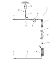
図1は血液回路の概略図である。人工透析治療等のように体外循環による血液浄化療法に使用する血液回路1は、図1に示すように、穿刺針2と穿刺針3とを結ぶチューブ4からなる第1経路Aの途中に、血液ポンプ5が当接される可撓性チューブ6と、ドリップチャンバー7,8、及び血液浄化器9が配設され、T管10により枝分かれした第2経路Bの途中に輸液チャンバー11が配設されている。また、第2経路Bの先端は、輸液容器12に接続されており、プライミング時に第2経路Bを介して第1経路Aに生理食塩水を供給するとともに、場合によっては血液が第1経路Aを循環中、輸液剤の注入又は輸血を行い得る構成とされている。そして、この血液回路1では、第1経路Aの大部分を構成しているチューブ4とドリップチャンバー7,8を、外部から内部の血液通過を透視可能な内部透視部として機能させている。
DESCRIPTION OF EXEMPLARY EMBODIMENTS Hereinafter, the best embodiment of the invention will be described with reference to the drawings.
FIG. 1 is a schematic diagram of a blood circuit. As shown in FIG. 1, a blood circuit 1 used for blood purification therapy by extracorporeal circulation such as an artificial dialysis treatment is in the middle of a first path A composed of a
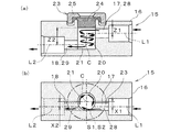
そして、血液回路1の途中部分、具体的には、チューブ4の途中部分には、混注部材(アクセスポートまたは接続部材)15を備えている。混注部材15は、血液回路1の上流部と下流部とを接続する部材であり、血液回路1中(すなわち血液回路1中を流れる血液中)に薬液などを注入したり、あるいは血液回路1から血液を採取したりするための構成を備えている。具体的に説明すると、混注部材15は、図2に示すように、長尺なハウジング16を備え、該ハウジング16の長手方向に沿って流入通路17と流出通路18とを開設し、流入通路17には血液回路1の上流部、詳しくは混注部材15よりも上流側に位置するチューブ4を連通し、流出通路18には血液回路1の下流部、詳しくは混注部材15よりも下流側に位置するチューブ4を連通する接続口をそれぞれ形成している。そして、ハウジング16の略中央部分には、縦向き円柱状の連通室21を形成し、該連通室21を形成する内壁20を円筒状の曲面および該曲面の一端を閉塞する円形平面で構成し、内壁20に流入通路17および流出通路18を貫通している。したがって、連通室21を介して流入通路17と流出通路18とを連通している。なお、流入通路17および流出通路18の接続口は、連通室21とは反対側の部分、言い換えるとハウジング16の端部側に位置する部分をチューブ4の外径と略同じ直径まで拡径し、該拡径部にチューブ4を挿入して接続するように構成されている。
Further, a mixed injection member (access port or connecting member) 15 is provided in the middle part of the blood circuit 1, specifically, in the middle part of the
さらに、連通室21の内壁20の一部には、薬剤を注入するための注入針や、採血するための採血針などの穿刺管(図示せず)を穿脱可能な穿脱部23を設けている。具体的には、連通室21の内壁20のうち、流入通路17または流出通路18が接続される箇所とは異なる箇所を開放し、該開放口に穿脱部23を設けている。穿脱部23は、図2(a)に示すように、内壁20の側部にゴム製の栓体24(所謂ゴムボタン)を配置して開放口を液密状態で閉塞し、この状態で栓体24の縁部をカバー25で覆い、該カバー25をハウジング16に止着して栓体24が脱落することを阻止している。また、カバー25の中央部分には貫通口25aを穿刺管が十分に通過可能な程度の大きさで開設し、該貫通口25aから栓体24を外方(言い換えると連通室21とは反対方向)へ露出している。したがって、貫通口25aを介して栓体24に穿刺管を穿刺すれば、穿刺管と連通室21とを連通することができ、ひいては穿刺管と血液回路1の内部とを連通できるように構成されている。なお、連通室21は、穿脱部23が設けられる端部、言い換えると穿脱部23のうち連通室21に露出する面を流入通路17の縁部(上縁部)および流出通路18の縁部(上縁部)と略同一平面上に位置させている。
Further, a part of the
そして、混注部材15は、流入通路17の中心軸(流入側中心軸)L1を流出通路18の中心軸(流出側中心軸)L2の延長線上から穿脱部23の側方寄りに外れた位置に設定している。詳しく説明すると、図2(a)に示すように、流入側中心軸L1と穿脱部23(栓体24)との離間距離(流入側離間距離)Z1を、流出側中心軸L2と穿脱部23(栓体24)との離間距離(流出側離間距離)Z2に等しく設定している。すなわち、ハウジング16の側方から見て、流入側中心軸L1と流出側中心軸L2とが同一平面上に配置される状態に設定している。また、図2(b)に示すように、流出側中心軸L2をその延長線が連通室21の中心から穿脱部23の側方寄り(詳しくは、カバー25の縁部寄り)に外れた状態に設定し、流入側中心軸L1を連通室21の中心を挟んで流出通路18とは反対の位置に設定している。この結果、混注部材15は、流入通路17、連通室21、流出通路18を連通することにより、穿脱部23がハウジング16の上部に配置された姿勢で横方向へ屈曲した流路を形成することになる。
The
さらに、流入通路17を形成する壁部を流入内壁28とし、該流入内壁28の一部、具体的には流入内壁28のうち流入側中心軸L1を挟んで連通室21の中心Cとは反対側に位置する側部を、内壁20の接線(流入側接線)S1上に配置している。また、流出通路18を形成する壁部を流出内壁29とし、該流出内壁29の一部、具体的には流出内壁29のうち流出側中心軸L2を挟んで連通室21の中心とは反対側に位置する側部を、内壁20の接線上、詳しくは流入側接線とは異なる接線(流出側接線)S2上に配置している。
Further, a wall portion forming the inflow passage 17 is defined as an inflow
このような構成を備えた混注部材15において、血液を血液回路1の上流側から流入すると、血液は、流入通路17を通って連通室21に流入する。このとき、流入側接線S1上に流入内壁28の側部を配置しているので、流入通路17から流入した血液をスムーズに連通室21内へ誘導することができ、血液の流速が低下することを抑えることができる。また、血液中の血球成分が内壁20に激しく衝突して損傷する不具合を避けることができる。
In the
さらに、連通室21に流入した血液は、連通室21の一側から中心Cあるいは中心Cの近傍を通って他側へ流れる。そして、流出通路18に到達し、該流出通路18から血液回路1の下流部へ流出する。このようにして、混注部材15は、血流を屈曲させることができ、連通室21に血液を乱流状態で流すことができる。したがって、連通室21内に血液が滞留する不都合、ひいては滞留した血液で血栓が形成される不都合を抑えることができる。このことから、混注部材15よりも下流側に配置されたドリップチャンバー8内のメッシュに血栓が詰まる虞をなくすことができ、安定した透析治療を行うことができる。また、採血時には、穿脱部23を介して連通室21に連通した穿刺管が血栓で詰まる虞がなく、採血を円滑に行うことができる。また、穿脱部23に穿刺管を穿刺した場合には、この穿刺管を横切るようにして血液を乱流状態で流すことができる。したがって、注入液を速やかに血液中に分散させることができる。さらに、流出側接線S2上に流出内壁29の側部を配置しているで、連通室21内の血液をスムーズに流出通路18へ誘導することができ、流出通路18へ流下した血液の流速が低下することを抑えることができる。
Further, the blood flowing into the
そして、血液を乱流状態にするために連通室21に障害物を配置する必要がなく、血液中の血球成分が障害物に衝突して損傷する不具合を避けることができる。また、流入通路17および流出通路18の配置設定を変えるだけで血栓の発生を抑えることができる。したがって、血栓が発生し難い混注部材15の製造コストの低減を図ることができる。
Further, it is not necessary to place an obstacle in the
なお、流入通路17および流出通路18は、いずれも中心軸L1,L2の延長線が連通室21の中心Cから外れる状態に設定されなくてもよい。要は、流入側中心軸L1が流出側中心軸L2の延長線上から外れた位置に設定されればよく、流入側中心軸L1の延長線または流出側中心軸L2の延長線のうちいずれか一方が連通室21の中心Cから外れる状態に設定してもよい。
Note that the inflow passage 17 and the
ところで、上記実施形態では、流入側中心軸L1を流出側中心軸L2の延長線上から穿脱部23の側方寄りに外れた位置、すなわち水平方向にオフセットさせた位置に設定したが、本発明はこれに限定されない。例えば、図3に示す第2実施形態の混注部材15においては、ハウジング16の側方から見て流入側中心軸L1を流出側中心軸L2の延長線上から外れた位置、すなわち上下方向にオフセットさせた位置に設定し、穿脱部23側から見て流入側中心軸L1と流出側中心軸L2とを同一縦平面上に配置している。詳しく説明すると、図3(a)に示すように、流入側中心軸L1と穿脱部23(栓体24)との離間距離(流入側離間距離)Z1を、流出側中心軸L2と穿脱部23(栓体24)との離間距離(流出側離間距離)Z2とは異ならせて、流入側離間距離Z1を流出側離間距離Z2よりも短く設定している。この結果、混注部材15は、流入通路17、連通室21、流出通路18を連通することにより、穿脱部23がハウジング16の上部に配置された姿勢で縦方向へ屈曲した流路を形成する。また、図3(b)に示すように、流入側中心軸L1および流出側中心軸L2をいずれも穿脱部23の同じ側部寄りに外れた位置に設定するとともに、流入側中心軸L1から連通室21の中心Cまでの離間距離X1と、流出側中心軸L2から連通室21の中心Cまでの離間距離X2とを等しく設定している。
By the way, in the above embodiment, the inflow side central axis L1 is set at a position deviated from the extension line of the outflow side central axis L2 toward the side of the piercing
さらに、流入通路17および流出通路18を連通室21の一側寄りに配置し、流入内壁28のうち流入側中心軸L1を挟んで連通室21の中心とは反対側に位置する側部を、内壁20の接線(流入側接線)S1上に配置している。また、流出内壁29のうち流出側中心軸L2を挟んで連通室21の中心とは反対側に位置する側部を、流入側接線S1よりも穿脱部23から離れた位置に配置された内壁20の接線(流出側接線)S2上に配置している。なお、流入側接線S1と流出側接線S2とは、内壁20に接する同一平面上に配置されている。
Furthermore, the inflow passage 17 and the
このような構成を備えた混注部材15に血液を血液回路1の上流側から流入すれば、血液を内壁20に沿わせて螺旋状に旋回させ、この旋回状態で穿脱部23から離れる方向、言い換えると穿脱部23に穿刺される穿刺管の延設方向へ沿って流すことができる。したがって、連通室21内で血液を攪拌しながら乱流状態で流すことができ、連通室21内に血液が滞留する不都合、ひいては血栓が形成される不都合を一層抑制することができる。
If blood flows into the
なお、流入側離間距離Z1を流出側離間距離Z2よりも長く設定してもよく、この設定の場合には、血液を内壁20に沿わせて螺旋状に旋回させ、この旋回状態で穿脱部23に近づく方向へ流すことができる。
The inflow side separation distance Z1 may be set longer than the outflow side separation distance Z2, and in this case, blood is swirled along the
ところで、上記実施形態では、流入側中心軸L1を流出側中心軸L2の延長線上から穿脱部23の側部寄りに外れた位置に設定したり、あるいは、離間距離Z1,Z2を異ならせる方向に外れた位置に設定したりしたが、本発明はこれに限定されない。すなわち、流入側中心軸L1を流出側中心軸L2の延長線上から穿脱部23の側部寄りに外れた位置に設定し、且つ流入側離間距離Z1を流出側離間距離Z2とは異ならせる状態に設定してもよい。また、上記実施形態では、流入側中心軸L1を流出側中心軸L2に対して平行となる状態に設定したが、本発明はこれに限定されない。要は、流入側中心軸L1と流出側中心軸L2とが同一直線上に位置しなければよく、例えば、流入側中心軸L1を流出側中心軸L2に対して傾いた状態に設定してもよい。
By the way, in the said embodiment, the inflow side center axis L1 is set to the position which deviated from the extension line of the outflow side center axis L2 to the side part of the
1 血液回路
2,3 穿刺針
4 チューブ
5 血液ポンプ
6 可撓性チューブ
7,8 ドリップチャンバー
9 血液浄化器
10 T管
11 輸液チャンバー
12 輸液容器
15 混注部材
16 ハウジング
17 流入通路
18 流出通路
20 内壁
21 連通室
23 穿脱部
24 栓体
25 カバー
25a 貫通口
28 流入内壁
29 流出内壁
DESCRIPTION OF SYMBOLS 1
Claims (6)
前記連通室を、前記穿刺管の穿脱方向に沿った方向の円柱状に形成して該連通室の内壁を曲面とし、
前記流入通路の中心軸と前記流出流路の中心軸とを、前記穿刺管の穿脱方向と略直交する状態で連通室の中心軸から外れた位置に配置し、且つ、流入通路の中心軸を流出通路の中心軸の延長線上から外れた位置に設定して流入通路から流入した血液が連通室内で旋回するように構成したことを特徴とする混注部材。 An inflow passage through which blood can flow in through the upstream portion of the blood circuit; an outflow passage through which blood can flow out through the downstream portion of the blood circuit; and a communication chamber that connects the inflow passage and outflow passage. A co-infusion member that is provided with a piercing portion through which a puncture tube can be pierced in a part of the inner wall of the communication chamber, and is capable of communicating the communication chamber and the puncture tube via the piercing portion,
The communication chamber is formed in a cylindrical shape in a direction along the piercing direction of the puncture tube, and the inner wall of the communication chamber is a curved surface,
The central axis of the inflow passage and the central axis of the outflow passage are arranged at positions away from the central axis of the communication chamber in a state substantially orthogonal to the piercing direction of the puncture tube, and the central axis of the inflow passage Is set at a position deviating from the extension line of the central axis of the outflow passage so that blood flowing in from the inflow passage is swirled in the communication chamber .
Priority Applications (1)
| Application Number | Priority Date | Filing Date | Title |
|---|---|---|---|
| JP2007204149A JP5128200B2 (en) | 2007-08-06 | 2007-08-06 | Mixed injection material |
Applications Claiming Priority (1)
| Application Number | Priority Date | Filing Date | Title |
|---|---|---|---|
| JP2007204149A JP5128200B2 (en) | 2007-08-06 | 2007-08-06 | Mixed injection material |
Publications (2)
| Publication Number | Publication Date |
|---|---|
| JP2009039158A JP2009039158A (en) | 2009-02-26 |
| JP5128200B2 true JP5128200B2 (en) | 2013-01-23 |
Family
ID=40440590
Family Applications (1)
| Application Number | Title | Priority Date | Filing Date |
|---|---|---|---|
| JP2007204149A Active JP5128200B2 (en) | 2007-08-06 | 2007-08-06 | Mixed injection material |
Country Status (1)
| Country | Link |
|---|---|
| JP (1) | JP5128200B2 (en) |
Families Citing this family (3)
| Publication number | Priority date | Publication date | Assignee | Title |
|---|---|---|---|---|
| JP5826815B2 (en) * | 2013-12-11 | 2015-12-02 | 日機装株式会社 | Mixed injection material |
| CN111166964A (en) * | 2020-03-05 | 2020-05-19 | 安徽宏宇五洲医疗器械股份有限公司 | Multifunctional blood transfusion set |
| WO2024252632A1 (en) * | 2023-06-08 | 2024-12-12 | スーガン株式会社 | Mixing stopcock |
Family Cites Families (4)
| Publication number | Priority date | Publication date | Assignee | Title |
|---|---|---|---|---|
| CA1042299A (en) * | 1974-05-31 | 1978-11-14 | Baxter Travenol Laboratories | Injection site |
| US4048996A (en) * | 1976-06-14 | 1977-09-20 | Baxter Travenol Laboratories, Inc. | Dual injection site |
| JPH07236697A (en) * | 1994-02-28 | 1995-09-12 | Nippon Zeon Co Ltd | Infusion set |
| JP4556701B2 (en) * | 2005-02-17 | 2010-10-06 | 株式会社ジェイ・エム・エス | Channel switching device |
-
2007
- 2007-08-06 JP JP2007204149A patent/JP5128200B2/en active Active
Also Published As
| Publication number | Publication date |
|---|---|
| JP2009039158A (en) | 2009-02-26 |
Similar Documents
| Publication | Publication Date | Title |
|---|---|---|
| CN103826693B (en) | Adapter | |
| US10315022B2 (en) | Co-injection member | |
| US8337451B2 (en) | Recirculation minimizing catheter | |
| ES2211960T3 (en) | SET OF BLOOD PIPES FOR DIALYSIS. | |
| EP1998842B1 (en) | Venous access port base | |
| JP2002512553A (en) | Horizontal bubble trap | |
| JP2020534957A (en) | Peripheral intravenous catheter with flow diversion characteristics | |
| KR101728236B1 (en) | Sap set of three-way valve | |
| ES2767931T3 (en) | Fluid interface device to deliver fluid and / or withdraw fluid from a patient | |
| JP2007521913A (en) | Dialysis catheter tip | |
| US8079990B2 (en) | Implantable catheter port | |
| JP5128200B2 (en) | Mixed injection material | |
| IL299826A (en) | Medical device having non-filtered csf withdrawal pathway | |
| EP3266477A1 (en) | Air trap chamber | |
| KR20190001420U (en) | infusion solution filter with one-way valve | |
| KR101674194B1 (en) | Adjustable travel path for liquid injector connector | |
| KR20160029497A (en) | Medical feeltering member for inning drug | |
| JP2022521354A5 (en) | ||
| JP5255344B2 (en) | Mixed injection material | |
| WO2022186352A1 (en) | Air trap chamber | |
| JP4549740B2 (en) | Plug for temporary closure | |
| CN117320767A (en) | Infusion part of the blood tube system | |
| JP2006129884A (en) | Mixed injection member, connecting member and medical device | |
| JP5019242B1 (en) | Medical infusion intravenous injection device | |
| CN109172928A (en) | A kind of injection catheter check-valves |
Legal Events
| Date | Code | Title | Description |
|---|---|---|---|
| A621 | Written request for application examination |
Free format text: JAPANESE INTERMEDIATE CODE: A621 Effective date: 20100510 |
|
| A977 | Report on retrieval |
Free format text: JAPANESE INTERMEDIATE CODE: A971007 Effective date: 20120209 |
|
| A131 | Notification of reasons for refusal |
Free format text: JAPANESE INTERMEDIATE CODE: A131 Effective date: 20120221 |
|
| A521 | Request for written amendment filed |
Free format text: JAPANESE INTERMEDIATE CODE: A523 Effective date: 20120419 |
|
| TRDD | Decision of grant or rejection written | ||
| A01 | Written decision to grant a patent or to grant a registration (utility model) |
Free format text: JAPANESE INTERMEDIATE CODE: A01 Effective date: 20121009 |
|
| A01 | Written decision to grant a patent or to grant a registration (utility model) |
Free format text: JAPANESE INTERMEDIATE CODE: A01 |
|
| A61 | First payment of annual fees (during grant procedure) |
Free format text: JAPANESE INTERMEDIATE CODE: A61 Effective date: 20121031 |
|
| R150 | Certificate of patent or registration of utility model |
Free format text: JAPANESE INTERMEDIATE CODE: R150 Ref document number: 5128200 Country of ref document: JP Free format text: JAPANESE INTERMEDIATE CODE: R150 |
|
| FPAY | Renewal fee payment (event date is renewal date of database) |
Free format text: PAYMENT UNTIL: 20151109 Year of fee payment: 3 |
|
| R250 | Receipt of annual fees |
Free format text: JAPANESE INTERMEDIATE CODE: R250 |
|
| R250 | Receipt of annual fees |
Free format text: JAPANESE INTERMEDIATE CODE: R250 |
|
| R250 | Receipt of annual fees |
Free format text: JAPANESE INTERMEDIATE CODE: R250 |
|
| R250 | Receipt of annual fees |
Free format text: JAPANESE INTERMEDIATE CODE: R250 |
|
| R250 | Receipt of annual fees |
Free format text: JAPANESE INTERMEDIATE CODE: R250 |
|
| R250 | Receipt of annual fees |
Free format text: JAPANESE INTERMEDIATE CODE: R250 |
|
| R250 | Receipt of annual fees |
Free format text: JAPANESE INTERMEDIATE CODE: R250 |
|
| R250 | Receipt of annual fees |
Free format text: JAPANESE INTERMEDIATE CODE: R250 |
|
| R250 | Receipt of annual fees |
Free format text: JAPANESE INTERMEDIATE CODE: R250 |