WO2022185666A1 - 建設機械 - Google Patents
建設機械 Download PDFInfo
- Publication number
- WO2022185666A1 WO2022185666A1 PCT/JP2021/046751 JP2021046751W WO2022185666A1 WO 2022185666 A1 WO2022185666 A1 WO 2022185666A1 JP 2021046751 W JP2021046751 W JP 2021046751W WO 2022185666 A1 WO2022185666 A1 WO 2022185666A1
- Authority
- WO
- WIPO (PCT)
- Prior art keywords
- construction machine
- turning
- main body
- machine according
- working device
- Prior art date
Links
- 238000010276 construction Methods 0.000 title claims abstract description 53
- QGZKDVFQNNGYKY-UHFFFAOYSA-N Ammonia Chemical group N QGZKDVFQNNGYKY-UHFFFAOYSA-N 0.000 claims description 44
- 239000002828 fuel tank Substances 0.000 claims description 43
- 239000000446 fuel Substances 0.000 claims description 28
- 229910021529 ammonia Inorganic materials 0.000 claims description 20
- 239000007788 liquid Substances 0.000 claims description 19
- 239000005431 greenhouse gas Substances 0.000 claims description 14
- 238000001514 detection method Methods 0.000 claims description 7
- 230000000903 blocking effect Effects 0.000 claims 2
- 238000009412 basement excavation Methods 0.000 description 50
- 238000010586 diagram Methods 0.000 description 28
- 238000003384 imaging method Methods 0.000 description 27
- 238000004891 communication Methods 0.000 description 15
- 230000005540 biological transmission Effects 0.000 description 13
- 238000000034 method Methods 0.000 description 10
- 239000000463 material Substances 0.000 description 6
- 230000007246 mechanism Effects 0.000 description 6
- 230000008569 process Effects 0.000 description 6
- 239000007789 gas Substances 0.000 description 5
- UFHFLCQGNIYNRP-UHFFFAOYSA-N Hydrogen Chemical compound [H][H] UFHFLCQGNIYNRP-UHFFFAOYSA-N 0.000 description 4
- 238000012423 maintenance Methods 0.000 description 4
- 238000002360 preparation method Methods 0.000 description 3
- 230000005856 abnormality Effects 0.000 description 2
- 230000001133 acceleration Effects 0.000 description 2
- 238000002485 combustion reaction Methods 0.000 description 2
- 238000012937 correction Methods 0.000 description 2
- 230000005484 gravity Effects 0.000 description 2
- 239000001257 hydrogen Substances 0.000 description 2
- 229910052739 hydrogen Inorganic materials 0.000 description 2
- 238000005259 measurement Methods 0.000 description 2
- VNWKTOKETHGBQD-UHFFFAOYSA-N methane Chemical compound C VNWKTOKETHGBQD-UHFFFAOYSA-N 0.000 description 2
- 238000010248 power generation Methods 0.000 description 2
- RZVHIXYEVGDQDX-UHFFFAOYSA-N 9,10-anthraquinone Chemical compound C1=CC=C2C(=O)C3=CC=CC=C3C(=O)C2=C1 RZVHIXYEVGDQDX-UHFFFAOYSA-N 0.000 description 1
- XEEYBQQBJWHFJM-UHFFFAOYSA-N Iron Chemical compound [Fe] XEEYBQQBJWHFJM-UHFFFAOYSA-N 0.000 description 1
- WHXSMMKQMYFTQS-UHFFFAOYSA-N Lithium Chemical compound [Li] WHXSMMKQMYFTQS-UHFFFAOYSA-N 0.000 description 1
- HBBGRARXTFLTSG-UHFFFAOYSA-N Lithium ion Chemical compound [Li+] HBBGRARXTFLTSG-UHFFFAOYSA-N 0.000 description 1
- 229910000990 Ni alloy Inorganic materials 0.000 description 1
- 230000008602 contraction Effects 0.000 description 1
- 239000013078 crystal Substances 0.000 description 1
- 230000000694 effects Effects 0.000 description 1
- 230000005611 electricity Effects 0.000 description 1
- 238000005868 electrolysis reaction Methods 0.000 description 1
- 230000005674 electromagnetic induction Effects 0.000 description 1
- 239000000835 fiber Substances 0.000 description 1
- 238000007667 floating Methods 0.000 description 1
- 230000006870 function Effects 0.000 description 1
- 239000003502 gasoline Substances 0.000 description 1
- 229910052744 lithium Inorganic materials 0.000 description 1
- 229910001416 lithium ion Inorganic materials 0.000 description 1
- 238000001646 magnetic resonance method Methods 0.000 description 1
- 239000002184 metal Substances 0.000 description 1
- 229910052751 metal Inorganic materials 0.000 description 1
- 238000012986 modification Methods 0.000 description 1
- 230000004048 modification Effects 0.000 description 1
- PXHVJJICTQNCMI-UHFFFAOYSA-N nickel Substances [Ni] PXHVJJICTQNCMI-UHFFFAOYSA-N 0.000 description 1
- 229910000069 nitrogen hydride Inorganic materials 0.000 description 1
- 230000003287 optical effect Effects 0.000 description 1
- 230000000149 penetrating effect Effects 0.000 description 1
- 229910000889 permalloy Inorganic materials 0.000 description 1
- 229920000642 polymer Polymers 0.000 description 1
- 238000012545 processing Methods 0.000 description 1
- 230000009467 reduction Effects 0.000 description 1
- 239000004065 semiconductor Substances 0.000 description 1
- 239000007787 solid Substances 0.000 description 1
- 230000000087 stabilizing effect Effects 0.000 description 1
- 239000006200 vaporizer Substances 0.000 description 1
- XLYOFNOQVPJJNP-UHFFFAOYSA-N water Substances O XLYOFNOQVPJJNP-UHFFFAOYSA-N 0.000 description 1
- 238000005303 weighing Methods 0.000 description 1
Images


Classifications
-
- E—FIXED CONSTRUCTIONS
- E02—HYDRAULIC ENGINEERING; FOUNDATIONS; SOIL SHIFTING
- E02F—DREDGING; SOIL-SHIFTING
- E02F9/00—Component parts of dredgers or soil-shifting machines, not restricted to one of the kinds covered by groups E02F3/00 - E02F7/00
-
- E—FIXED CONSTRUCTIONS
- E02—HYDRAULIC ENGINEERING; FOUNDATIONS; SOIL SHIFTING
- E02F—DREDGING; SOIL-SHIFTING
- E02F9/00—Component parts of dredgers or soil-shifting machines, not restricted to one of the kinds covered by groups E02F3/00 - E02F7/00
- E02F9/18—Counterweights
Definitions
- the present invention relates to a construction machine such as a hydraulic excavator that performs excavation and loading work, and more particularly to a construction machine with a high degree of layout freedom or a construction machine that emits less greenhouse gases.
- Patent Document 1 discloses automation of excavation work. Vehicles that emit less greenhouse gas are being developed, and Patent Document 2 discloses that a fuel cell is also applied to a backhoe.
- Patent Document 1 is a construction machine having a driver's seat, there are restrictions on the layout of the construction machine. Further, although Patent Document 2 discloses details of the fuel cell, it does not disclose how to mount the fuel cell on the construction machine. Therefore, a construction machine that emits less greenhouse gas has not been realized.
- a second object of the present invention is to provide a construction machine that emits less greenhouse gases.
- a construction machine drives a body section that can be turned by turning a turning section, a work device connected to one end side of the body section, and at least one of the body section and the work device.
- a drive system and a mass body for compensating an unbalanced load acting on the body portion due to driving of the working device are provided, and the mass body holds at least part of the drive system.
- a construction machine comprises a main body portion that can be turned by turning a turning portion, a working device connected to one end side of the main body portion, and a greenhouse that is provided inside the other end side of the main body portion.
- a construction machine is a main body portion that can be turned by turning a first turning portion, a first working device connected to one end side of the main body portion, and a first working device connected to the other end side of the main body portion. a second working device, a housing section that can be turned by a second turning section different from the first turning section, and a liquid tank that is provided in the housing section and stores liquid fuel that does not emit greenhouse gases. I have.
- the drive system since at least part of the drive system is held by the mass body, it is possible to provide a construction machine with a high degree of freedom in layout.
- the liquid fuel that does not emit greenhouse gases since the liquid fuel that does not emit greenhouse gases is used, it is possible to realize a construction machine that emits less greenhouse gases.
- FIG.1 (a) is a top view
- FIG.1(b) is a front view.
- 3(a) is a view taken along line AA in FIG. 1(b)
- FIG. 3(b) is a view taken along line AA in FIG. 2(b).
- FIG. 4 is a flowchart executed by the heavy equipment control device of the first embodiment; It is a schematic diagram of the construction machine showing the 2nd Embodiment, Fig.6 (a) is a top view, FIG.6(b) is a front view.
- 9 is a flowchart executed by the heavy equipment control device 50 of the second embodiment; 8A and 8B are diagrams showing the excavation operation, FIG. 8A is a diagram showing the working device at the initial position, FIG. FIG. 8(c) is a diagram showing the state when excavation is completed, and FIG. 8(d) is a diagram showing the state after turning.
- 9A and 9B are diagrams showing the operation following the excavating operation in FIG. 8, FIG. 9A is a diagram showing the state of loading, and FIG.
- FIG. 9B is a diagram showing the working device at the initial position.
- FIG. 9(c) is a diagram showing a state after the upper body device is turned, and
- FIG. 9(d) is a diagram showing a state during excavation.
- 10(a) and 10(b) are schematic diagrams of a construction machine representing the third embodiment.
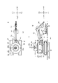
- FIG. 1A and 1B are schematic diagrams showing a hydraulic excavator 1 representing the present embodiment, FIG. 1(a) being a top view and FIG. 1(b) being a front view.
- FIG. 2 is a schematic diagram of the construction machine when the countermass 43 of the hydraulic excavator 1 of FIG. 1(b) moves in the -X direction.
- 3 is an AA arrow view of FIGS. 1 and 2
- FIG. 3(a) is an AA arrow view of FIG. 1(b)
- FIG. b) is a view taken along the line AA.
- FIG. 4 is a block diagram of the main part of the first embodiment.
- the hydraulic excavator 1 of this embodiment is an automatic driving type without a driver's seat, and has a UAV (Unmanned Aerial Vehicle, hereinafter referred to as a drone 100) which is an unmanned aerial vehicle.
- UAV Unmanned Aerial Vehicle
- the hydraulic excavator 1 may be automatically operated at a construction site and placed on a trailer for transportation on a public road. Further, the operation of the hydraulic excavator 1 may be automatic operation or remote operation at a remote location away from the excavation site.
- the hydraulic excavator 1 of this embodiment has a drive system 10 (see FIG. 4), a travel device 20, a swing device 30, a main device 40, and a working device 60.
- the hydraulic excavator 1 also has a drone 100 that can take off and land on a takeoff/landing section provided on the upper surface of the main unit 40 .
- a plurality of drones 100 may be used.
- the drone 100 may be of a type that flies by electric power, or may be of a type that flies by a fuel cell using hydrogen.
- the drive system 10 has an engine 11 , a fuel tank 12 , a leak sensor 13 and a generator 14 .
- the engine 11 is an internal combustion engine, and employs a diesel engine in this embodiment.
- the engine 11 burns fuel supplied from the fuel tank 12 to drive the generator 14 .
- the fuel tank 12 stores ammonia (NH3) in a liquid state in this embodiment, and is provided with a remaining amount meter (not shown) inside. Liquid ammonia is vaporized by a vaporizer (not shown), and the vaporized ammonia is combusted by the engine 11 together with air.
- a plurality of fuel tanks 12 may be provided as storage tanks for ammonia and storage tanks for light oil.
- the engine 11 may be a co-combustion type engine that co-combusts ammonia and light oil.
- the leakage sensor 13 is a liquid leakage sensor that detects leakage of liquid ammonia stored in the fuel tank 12 or a gas sensor that detects leakage of vaporized ammonia from the vicinity of the engine 11 .
- a liquid leakage sensor a contact type detection method in which electricity flows due to conduction through the liquid when the liquid contacts between two electrodes, or a fiber sensor is used to detect liquid leakage using reflection and transmission.
- a gas sensor there are a solid sensor using a semiconductor, a constant potential electrolysis type electrochemical sensor, an optical sensor using infrared rays, and the like, and any sensor can be used.
- both a liquid leak sensor and a gas sensor may be installed, or either one of them may be installed.
- the generator 14 is connected to the output shaft of the engine 11 and generates power by the rotational driving force of the output shaft of the engine 11. Electric power generated by the generator 14 is supplied to various cylinders and various motors as shown in the block diagram of FIG. Although details will be described later, in this embodiment, the engine 11, the fuel tank 12, and the generator 14 are mounted on a counter mass 43, which will be described later. Also, the engine 11 , the fuel tank 12 , and the generator 14 may be exposed to the outside of the main unit 40 as the counter mass 43 moves, so they are covered with the cover 19 .
- the traveling device 20 has a pair of crawler belts 23 wound around an idler wheel 21 and a driving wheel 22, and a traveling motor (not shown) that drives the driving wheels 22.
- the driving wheels 22 drive the pair of crawler belts 23.
- the traveling motor 24 is driven by electric power supplied from the generator 14, and in this embodiment, an in-wheel motor provided so as to be coaxially connected to the drive wheel 22 or the hub of the drive wheel 22 is employed. .
- the swing device 30 is arranged on the travel device 20 and the main device 40 .
- the turning device 30 includes a bearing (not shown) and a turning motor 31 to which electric power is supplied from the generator 14, and turns the main body device 40 and the work device 60. As shown in FIG. Note that the turning of the main unit 40 and the working device 60 by the turning device 30 may be performed using hydraulic pressure instead of the turning motor 31 .
- the main unit 40 has a flat upper surface, and has a power transmission device 15 for supplying electric power to the drone 100 and a shield member 16 on the upper surface. Also, the power transmission device 15 on the upper surface of the main unit 40 serves as the takeoff and landing part of the drone 100 .
- the power transmitting device 15 supplies power to a power receiving device 103 of the drone 100, which will be described later, and adopts wireless power feeding in this embodiment.
- Wireless power supply supplies electric power to the power receiving apparatus 103 in a non-contact manner, and known methods include a magnetic resonance method and an electromagnetic induction method.
- the power transmission device 15 of this embodiment includes a power supply, a control circuit, and a power transmission coil. Also, the power transmission device 15 may be of a spatial transmission type instead of the proximity junction type described above. Spatial transmission type power supply uses electromagnetic waves such as microwaves to supply power to an object (the power receiving device 103 of the drone 100 in this embodiment) at a distance of several meters to several tens of meters.
- a contact-type power supply method may be used instead of wireless power supply.
- the power transmitting device 15 and the power receiving device 103 may each be provided with a metal contact, and power may be supplied by mechanically connecting the contacts.
- the take-off/landing section may be provided with a concave contact point, and the drone 100 side may be provided with a convex contact point.
- One concave contact and one convex contact may be provided, or a plurality of contacts may be provided.
- the shield member 16 shields electromagnetic noise, and in this embodiment prevents electromagnetic noise generated from the power transmission device 15 and the like from affecting the antenna 48a described later.
- the shield member 16 is provided so as to surround the power transmission device 15, and also surrounds the drone 100 when the drone 100 lands on the takeoff/landing section. there is The shield member 16 does not surround the entire drone 100, but only needs to shield electromagnetic noise that may be generated from the battery 105 and the second communication device 106, which will be described later. Therefore, the shield member 16 surrounds the power transmission device 15 and at least part of the drone 100 .
- permalloy which is an alloy of nickel (Ni) and iron (Fe), can be used.
- a working device 60 is connected to the side surface of the main device 40 via a swing portion 41 and a swing cylinder 42 .
- the body device 40 also contains an attitude detector 18, a counter mass 43, a pair of sliders 44, and a pair of sliders 44.
- the main unit 40 also has an opening (not shown) through which the cover 19 and the countermass 43 move to the outside of the main unit 40 .
- An opening/closing portion for opening/closing the opening may be provided.
- the cover 19 may be omitted when this opening/closing portion is provided.
- the orientation detector 18 is a sensor that is attached inside the main unit 40 and detects the orientation of the main unit 40 .
- the attitude detector 18 an inclinometer, a spirit level, or the like can be used.
- the countermass 43 corrects the unbalanced load acting on the hydraulic excavator 1 when the work device 60 is driven, and is provided on the main device 40 so as to be on the opposite side of the work device 60 .
- the countermass 43 is provided on the lower side of the main unit 40 and attached to a pair of sliders 44 spaced apart in the Y direction.
- the pair of sliders 44 extends in the X direction and is supported by a pair of bases 45 so as to be movable in the X direction.
- the conventional countermass is provided along the Z direction, which is the vertical direction
- the countermass 43 of this embodiment is provided along the XY plane perpendicular to the Z direction. Thereby, the center of gravity of the hydraulic excavator 1 can be lowered.
- the countermass motor 46 moves the countermass 43 by moving the pair of sliders 44 along the pair of bases 45 .
- the counter mass 43 moves to the -X side
- the counter mass 43 moves to the +X side.
- 43 moves to the +X side.
- the counter mass 43 moves to the -Y side.
- the size of the excavator 1 depends on the size of the bucket 58 , and the size and weight of the engine 11 , the fuel tank 12 , the generator 14 , and the countermass 43 that make up the excavator 1 also depend on the size of the bucket 58 . depends on Therefore, depending on the size of the bucket 58, a weight of about 1.5 to 4 tons is required to correct the unbalanced load acting on the hydraulic excavator 1 when the working device 60 is driven.
- the weight of the engine 11 is about 350 Kg to 600 Kg
- the weight of the fuel tank 12 when full is about 120 Kg to 400 Kg
- the weight of the generator 14 is about 450 Kg to 750 Kg.
- the weight required for the counter mass 43 is about 580 Kg to 2750 Kg.
- the weight of the counter mass 43 can be reduced.
- the countermass 43 does not need to mount all of the engine 11, the fuel tank 12, and the generator 14, and mounts at least one of the engine 11, the fuel tank 12, and the generator 14. do it. Therefore, the counter mass 43 and the mass placed on the counter mass 43 serve as mass bodies for correcting the unbalanced load acting on the hydraulic excavator 1 .
- the weight of the fuel tank 12 becomes lighter as the fuel is used.
- the weight of the counter mass 43 may be set assuming that the fuel tank 12 is empty, or the counter mass 43 may be moved by the counter mass motor 46 as the fuel is used. good.
- the weight of the counter mass 43 may be further reduced. If the countermass 43 is not moved, the pair of sliders 44, the pair of bases 45, and the countermass motor 46 may be omitted. However, even when the countermass 43 is not moved, the pair of sliders 44, the pair of bases 45, and the countermass motor 46 are used to move the engine 11, the fuel tank 12, and the generator 14 to the main unit.
- the swing portion 41 is pivotally supported such that a portion connected to the main device 40 and a portion connected to the boom 53 are rotatable about the Z axis.
- the swing cylinder 42 is a cylinder having one end connected to the main unit 40 and the other end connected to the swing portion 41 , and is expanded and contracted by electric power supplied from the generator 14 .
- the expansion and contraction of the swing cylinder 42 drives the working device 60 clockwise or counterclockwise in FIG. 1(a).
- the boom cylinder 54 is a cylinder that is telescopically operated by electric power supplied from the generator 14 to drive the boom 53 .
- the arm cylinder 56 is a cylinder that is expanded and contracted by electric power supplied from the generator 14 to drive the arm 55 .
- the bucket cylinder 59 is a cylinder that is expanded and contracted by electric power supplied from the generator 14 to drive the bucket 58 .
- the swing cylinder 42, the boom cylinder 54, the arm cylinder 56, and the bucket cylinder 59 are driven by electric power from the generator 14, but hydraulic pressure is used to drive these cylinders. good too.
- the first GNSS 47 measures the position of the hydraulic excavator 1 using artificial satellites.
- the first communication device 48 is a wireless communication unit that has an antenna 48a, a transmitter, a receiver, various circuits, and the like, and accesses a second communication device 106, which will be described later, and a wide area network such as the Internet.
- the first communication device 48 communicates the flight path of the drone 100 to the second communication device 106 based on the position of the excavator 1 detected by the first GNSS 47 .
- two antennas 48a are shown in FIG. 1, the number may be one, or three or more.
- the first memory 49 is a non-volatile memory (for example, flash memory), and stores various data and programs for driving the hydraulic excavator 1 and various data and programs for automatically operating the hydraulic excavator 1.
- the first memory 49 also stores data on the flight path of the drone 100 .
- the heavy machinery control device 50 includes a CPU and is a control device that controls the entire hydraulic excavator 1 . It controls flight movements.
- a working device 60 is connected to the main device 40 via a swing portion 41 and a swing cylinder 42 .
- the work device 60 has a boom 53 , a boom cylinder 54 , an arm 55 , an arm cylinder 56 , a bucket 58 and a bucket cylinder 59 .
- the boom 53 is a V-shaped component connected to the main unit 40 via the swing portion 41 and is rotated by the boom cylinder 54 .
- the arm 55 is connected to the tip of the boom 53 and rotated by an arm cylinder 56 .
- a bucket 58 is connected to the tip of the arm 55 and rotated by a bucket cylinder 59 . It is also possible to attach a breaker or the like to the tip of the arm 55 instead of the bucket 58 .
- the drone 100 of this embodiment includes a flight device 101, an imaging device 102, a power receiving device 103, a sensor group 104, a battery 105, a second communication device 106, a second memory 107, and a UAV control device 108.
- the flight device 101 has a motor (not shown) and a plurality of propellers, and generates thrust to float the drone 100 in the air and to move the drone 100 in the air.
- the number of drones 100 that land on the take-off/landing section can be arbitrarily set.
- the configuration of each drone 100 may be the same, or a part thereof may be changed.
- the size of each drone 100 may be the same or may be different.
- the imaging device 102 is a digital camera that has a lens, an imaging device, an image processing engine, and the like, and captures moving images and still images. In this embodiment, the imaging device 102 performs surveying and imaging of excavated locations.
- the lens of the imaging device 102 is attached to the side surface (front) of the drone 100, but the lens of the imaging device 102 may be attached to the bottom surface of the drone 100, and a plurality of lenses may be attached. may be provided in the drone 100.
- a moving mechanism may be provided to move the lens attached to the side face downward.
- a mechanism for rotating the imaging device 102 around the Z-axis may be provided to position the lens of the imaging device 102 at an arbitrary position around the Z-axis.
- an omnidirectional camera 360-degree camera
- a three-dimensional scanner may be used instead of the imaging device 102.
- the power receiving device 103 has a power receiving coil and a charging circuit provided on the leg 109 of the drone 100 and charges the battery 105 with power from the power transmitting device 15 .
- the battery 105 is a secondary battery connected to the power receiving device 103, and can be a lithium ion secondary battery, a lithium polymer secondary battery, or the like, but is not limited thereto. Battery 105 is capable of supplying power to flight device 101 , imaging device 102 , second communication device 106 , second memory 107 and UAV controller 108 .
- the sensor group 104 includes GNSS, an infrared sensor for avoiding collision between the drone 100 and other devices (for example, the work device 60), an air pressure sensor for measuring altitude, a magnetic sensor for detecting orientation, and sensors for detecting the direction of the drone 100.
- a gyro sensor that detects an attitude an acceleration sensor that detects acceleration acting on the drone 100, and the like.
- the second communication device 106 has a wireless communication unit, accesses a wide area network such as the Internet, and communicates with the first communication device 48 .
- the second communication device 106 transmits image data captured by the imaging device 102 and detection results detected by the sensor group 104 to the first communication device 48, and receives flight commands from the first communication device 48. For example, it transmits to the UAV control device 108 .
- the second memory 107 is a non-volatile memory (for example, flash memory), stores various data and programs for flying the drone 100, and stores image data captured by the imaging device 102 and detections detected by the sensor group 104. It stores results and the like.
- non-volatile memory for example, flash memory
- the UAV control device 108 includes a CPU, an attitude control circuit, a flight control circuit, etc., and controls the drone 100 as a whole. Also, the UAV control device 108 determines the charging timing at the takeoff/landing part from the remaining amount of the battery 105, and controls the imaging position, angle of view, frame rate, and the like of the imaging device 102. FIG.
- the drone 100 surveys the excavation area prior to excavation by the work device 60, and during the excavation by the work device 60, images are taken from the sky, and the bucket Since the bucket can be imaged in the vicinity of 58, excavation can be performed even if the operator is not in the excavation area.
- the drone 100 captures images at the take-off and landing section, the images can be captured from substantially the same position as the driver's seat of the conventional hydraulic excavator.
- the second drone 100 can be charged at the takeoff and landing section, so the first drone 100 and The second drone 100 can be alternately flown.
- the number of drones 100 may be three or more.
- FIG. 5 is a flowchart executed by the heavy equipment control device 50 of this embodiment. It should be noted that the flowchart of FIG. 5 is assumed to be performed while the drive system 10 is being driven.
- the heavy machinery control device 50 determines whether or not the hydraulic excavator 1 has an abnormality (step S1). Here, the heavy equipment control device 50 determines whether or not ammonia is leaking from the output of the leak sensor 13. If ammonia is not leaking, the process proceeds to step S2, and if ammonia is leaking, the process proceeds to step S6. Stop 1. When the hydraulic excavator 1 is to be stopped due to ammonia leaking, the heavy machinery control device 50 opens an opening (not shown) of the main unit 40 so that the ammonia concentration does not remain in the main unit 40 in a high concentration state. do.
- the heavy equipment control device 50 may move a part of the engine 11 and the fuel tank 12 to the outside of the main unit 40 by driving the countermass motor 46 to move the countermass 43 . .
- the ammonia concentration in the main unit 40 can be lowered, and the maintainability of the engine 11 and the fuel tank 12 can be improved.
- an opening (not shown) may be provided in the cover 19, and the opening (not shown) may be opened by a motor (not shown) when ammonia is leaking. It is desirable that the opening of the opening (not shown) be performed at the timing when a portion of the counter mass 43 is exposed to the outside of the main unit 40 .
- the heavy machinery control device 50 performs excavation using the work device 60 based on a program for automatic operation of the work device 60 stored in the first memory 49, for example, based on the results of surveying using the drone 100 (step S2).
- the automatic operation program of the work device 60 is executed based on the position of the hydraulic excavator 1 positioned by the first GNSS 47 , the height of the excavated object at the excavation point, and specifications such as the excavation range of the work device 60 .
- This program also includes control of the travel device 20, the swing device 30, the swing cylinder 42, and the like. It should be noted that the excavation in step S2 may be remotely operated by an operator in a remote location instead of being automatically operated.
- the heavy equipment control device 50 determines whether it is necessary to correct the unbalanced load acting on the hydraulic excavator 1 by driving the countermass 43 by driving the work device 60 in step S2 (step S3).
- the weight of the countermass 43 is set such that it is not necessary to move the countermass 43 by driving the working device 60 when the fuel tank 12 is full.
- the heavy equipment control device 50 makes a determination in step S3 based on the output of a fuel gauge (not shown) provided in the fuel tank 12. It is assumed that the heavy equipment control device 50 determines that the remaining amount of the fuel tank 12 is less than 50%, for example, and proceeds to step S4. Also, when the remaining amount of fuel in the fuel tank 12 is 50% or more, the heavy equipment control device 50 proceeds to step S5, which will be described later. Note that the heavy equipment control device 50 moves the counter mass 43 based on the output of the attitude detector 18 instead of the output of the fuel gauge (not shown) or in combination with the output of the fuel gauge (not shown). You may make it judge whether to carry out.
- the heavy equipment control device 50 drives the countermass motor 46 to move the countermass 43 together with the engine 11, the fuel tank 12, and the generator 14 (step S4).
- the main unit 40 is preferably provided with an alarm. For example, it is desirable to provide a warning light on the main unit 40 to visually call attention, or to provide a speaker on the main unit 40 to audibly call attention, or both.
- the heavy equipment control device 50 determines whether or not the work by the working device 60 has ended (step S5). The heavy equipment control device 50 repeats steps S1 to S5 until the scheduled excavation work is completed, and proceeds to step S6 when the scheduled excavation work is completed.
- the heavy equipment control device 50 performs control to stop the hydraulic excavator 1 (step S6). Specifically, when the work device 60 is moved to the initial position and the counter mass 43 is moved to the outside of the main unit 40, the heavy equipment control device 50 moves the counter mass 43 to the inside of the main unit 40.
- the initial position means that the working device 60 is in a position where an unbalanced load is unlikely to occur (that is, a position where the portion extending in the X direction is small).
- the heavy equipment control device 50 stops driving the excavator 1, and ends this flowchart.
- the space where the driver's seat is eliminated is used to provide the countermass 43 along the XY plane perpendicular to the Z direction, and the countermass 43 includes the engine 11, the fuel tank 12, and the generator 14. is placed (held), the weight of the counter mass 43 can be reduced, and the hydraulic excavator 1 with a high degree of layout freedom can be realized.
- the fuel tank 12 is arranged on the other end side (-X side) of the main unit 40, but the engine 11 may be arranged on the other end side of the main unit 40, and the generator 14 may be arranged on the other end side of the main unit 40 .
- an ammonia concentration meter may be provided in the main unit 40, and when the ammonia concentration exceeds, for example, 20 ppm, the above-described alarm device may notify visually or audibly.
- a photovoltaic power generation device may be provided on the upper surface or the side surface of the main unit 40 and the electric power generated by the photovoltaic power generation device may be used to drive the hydraulic excavator 1 .
- the photovoltaic device may use, for example, perovskite solar cells.
- a perovskite solar cell is a solar cell using perovskite crystals, and because it is flexible, it can be attached to a structure having a curved surface. Moreover, since the perovskite solar cell is lightweight, it is possible to suppress an increase in the weight of the excavator 1 .
- the generator 14 when ammonia or the like, which does not emit greenhouse gases, is used as the fuel for the engine 11, a construction machine that emits less greenhouse gases can be realized. Note that light oil, gasoline, or the like may be used instead of ammonia if the emission of greenhouse gases is permitted.
- the generator 14 When the generator 14 is placed on the counter mass 34, the length of wiring for various cylinders and motors to which power is supplied from the generator 14 is determined in consideration of the movement stroke of the counter mass 34. It should be longer. Instead of this, the power supply from the generator 14 to various cylinders, various motors, etc. may be a spatial transmission type power supply (wireless power supply).
- FIGS. 6 to 9 The second embodiment will be described below with reference to FIGS. 6 to 9. The same reference numerals are given to the same components as in the first embodiment, and the description thereof will be omitted or simplified.
- illustration of the shield member 16, the cover 19, the antenna 48a, the drone 100, etc. is omitted in order to avoid complication of the drawing.
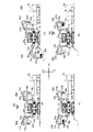
- 6A and 6B are schematic diagrams of a hydraulic excavator 1 representing an example of a construction machine representing the second embodiment.
- FIG. 6A is a top view
- FIG. 6B is a front view. The broken portion is shown as a partial cross-section.
- the turning device 30 and the main body device 40 are divided into two, and the work device 60 is two.
- the two pivots 30 are described as an upper pivot 30a and a lower pivot 30b.
- the swing motor 31 of the first embodiment is made up of two, an upper swing motor 31a and a lower swing motor 31b.
- the two main units 40 will be described as an upper main unit 40a and a lower main unit 40b. Since the construction of the two working devices 60 is the same as that of the first embodiment, one is designated as a working device 60a and the other is designated as a working device 60b. b.
- the upper body device 40a can be turned by an upper turning device 30a having bearings.
- the upper body device 40a also functions as a storage section, and includes the engine 11, the fuel tank 12, the generator 14, the countermass 43, and part of the upper turning motor 31a for turning the upper body device 40a. etc. is stored.
- the countermass 43 has a rectangular shape in the first embodiment, but has a circular shape in the present embodiment. 14 are placed. The shape of the counter mass 43 can be set arbitrarily.
- the unbalanced load acting on the excavator 1 due to the driving of the working device 60b can be corrected by the load of the working device 60a.
- the working device 60a is moved to -X, the unbalanced load acting on the hydraulic excavator 1 due to the driving of the working device 60a can be more corrected. Therefore, the weight of the counter mass 43 can be reduced or the counter mass 43 can be omitted in order to correct the unbalanced load by the load of the engine 11 and the generator 14 arranged on one end side of the counter mass 43. It is possible. Alternatively, only one of the engine 11 and the generator 14 may be mounted on the counter mass 43 to correct the unbalanced load.
- the fuel tank 12 has a cylindrical shape, which contributes to stabilizing the weight balance of the upper main unit 40a rather than correcting the unbalanced load. Therefore, the fuel tank 12 is not placed on the countermass 43 . Further, since the fuel tank 12 is used to stabilize the weight balance of the upper body device 40a, the reduction of the fuel in the fuel tank 12 does not affect the correction of the unbalanced load.
- the attitude detector 18 is preferably provided in the upper main unit 40a.
- an opening is formed in the center of the lower portion of the upper main unit 40a, and an upper slip ring 35 forming part of a slip ring mechanism, which will be described later, is engaged with this opening.
- the upper slip ring 35 has an opening, and wiring for supplying electric power to the lower turning motor 31b and the traveling motor 24 is routed through the opening. A part of the upper slip ring 35 turns along with the turning of the upper main body device 40a.
- the slip ring mechanism includes a lower slip ring 36, a fixed portion 37 connected to the non-rotating portion of the upper slip ring 35 and the non-rotating portion of the lower slip ring 36. have.
- the lower slip ring 36 is provided on the lower main body device 40b and supports the fixing portion 37 from the outside.
- the fixed part 37 is provided so as to penetrate the lower turning device 30b, and has an opening for routing the wiring from the upper slip ring 35. As shown in FIG. Therefore, even if the upper main body device 40a or the lower main body device 40b turns, the wires are routed by the slip ring mechanism, so that the wires are not tangled or disconnected. In addition, you may make it route piping of liquids (hydraulic pressure, water), gas, etc. using this slip-ring mechanism as needed.
- the lower body device 40b can be turned by a lower turning device 30b having bearings.
- the lower main unit 40b is connected to the working device 60a via the swing portion 41a and the swing cylinder 42a on the -X direction side, and is connected to the working device 60b via the swing portion 41b and the swing cylinder 42b on the +X direction side. ing. It is preferable that the working device 60a and the working device 60b are arranged symmetrically with respect to the lower main body device 40b. Further, by connecting the working device 60a and the working device 60b to the lower body device 40b, it is possible to prevent the center of gravity of the hydraulic excavator 1 from becoming high.
- the lower body device 40b accommodates a part of the lower turning motor 31b and the lower slip ring 36, and an opening for penetrating the fixing portion 37 is formed near the central portion.
- a large space is formed inside the lower main unit 40b. Therefore, maintenance tools for the hydraulic excavator 1, various replacement parts, the drone 100, replacement parts for the drone 100, and the like may be stored inside the lower main body device 40b. Further, when various cylinders are hydraulically driven, a hydraulic unit may be arranged inside the lower body device 40b.
- the upper body device 40a and the lower body device 40b are not limited to a cylindrical shape, and may be of any shape.
- the fuel tank 12 is placed on the counter mass 43 and the counter mass 43 is driven by the counter mass motor 46 .
- the pair of sliders 44, the pair of bases 45, and the countermass motor 46 can be omitted.
- FIG. 7 is a flowchart executed by the heavy equipment control device 50 of this embodiment
- FIG. 8 is a diagram showing an excavation operation
- FIG. 8(b) is a diagram showing the state during excavation
- FIG. 8(c) is a diagram showing the state when excavation is completed
- FIG. 8(d) is a diagram showing the state after turning.
- . 9A and 9B are diagrams showing the operation following the excavating operation in FIG. 8,
- FIG. 9A is a diagram showing the state of loading
- FIG. FIG. 9(c) is a diagram showing a state after the upper body device 40a is turned
- FIG. 9(d) is a diagram showing a state during excavation.
- FIG. 7 The flowchart of FIG. 7 will be described below with reference to FIGS. 8 and 9. 8 and 9, like FIG. 6, a portion surrounded by a dotted line is shown as a partial cross-sectional view. Also, in FIGS. 8 and 9, some symbols are omitted in order to avoid complication of the drawings.
- the initial position means that the two working devices 60 are at a position where an unbalanced load is unlikely to occur (that is, a position where the portion extending in the X direction is small).
- a part of the process may be performed by a worker in a remote location, for example, away from the civil engineering site.
- the heavy machinery control device 50 determines whether or not preparations for excavation by the hydraulic excavator 1 have been completed (step S11). As shown in FIG. 8A, the heavy equipment control device 50 is in a state where the hydraulic excavator 1 has arrived at the excavation site and is ready for excavation, and the dump truck 70 has arrived at the loading site. If the excavation preparation is completed, the process proceeds to step S12, otherwise step S11 is repeated. Here, it is assumed that preparation for excavation has been completed, and the process proceeds to step S12.
- the heavy machinery control device 50 performs excavation using a bucket 58a that constitutes a part of the working device 60a (step S12).
- the heavy equipment control device 50 flies the drone 100 in the vicinity of the bucket 58a and captures an image of the excavation operation with the bucket 58a with the imaging device 102, thereby confirming the excavation situation.
- the working device 60a and the working device 60b have the same configuration and therefore the same weight. However, as shown in FIG.
- the hydraulic excavator 1 when the work device 60a extends in the -X direction and the excavated material is accommodated in the bucket 58a, the hydraulic excavator 1 is subjected to a biased load in the -X direction. Therefore, in this embodiment, the offset load is corrected by positioning the engine 11 and the generator 14, which are housed in the upper main unit 40a and mounted by the countermass 43, in the +X direction. .
- the heavy equipment control device 50 determines whether excavation by the bucket 58a has ended (step S13).
- the heavy equipment control device 50 determines that the excavation by the bucket 58a is completed when it is determined that the bucket 58a contains a predetermined amount of excavated material from the image captured by the imaging device 102 of the drone 100 .
- a remote worker may determine whether or not the excavation by the bucket 58a has been completed based on the imaging result of the imaging device 102 of the drone 100 .
- a weight scale may be provided on the bucket 58a so that the heavy equipment control device 50 may determine whether or not a predetermined amount of excavated material has been stored in the bucket 58a based on the measurement result of the weight scale.
- step S14 it is assumed that the excavation by the bucket 58a is completed and the process proceeds to step S14.
- the heavy equipment control device 50 determines that the excavation by the bucket 58a is completed, it moves the working device 60a to the initial position as shown in FIG. 8(c). This is for the purpose of reducing the unbalanced load acting on the lower main body device 40b and the like due to the turning by the work device 60a in step S14, and for the safe turning.
- the heavy equipment control device 50 rotates the upper main body device 40a by 180 degrees with the upper turning motor 31a, and turns the lower main body device 40b by 180 degrees with the lower turning motor 31b (step S14).
- the lower body device 40b is turned to load the excavated material stored in the bucket 58a onto the dump truck 70 and to move the bucket 58b, which constitutes a part of the work device 60b, to the excavation position.
- the reason why the upper body device 40a is turned is to correct the unbalanced load acting on the hydraulic excavator 1 due to the turning of the lower body device 40b. As a result, it is possible to prevent the hydraulic excavator 1 from floating or overturning when the lower main unit 40b is turned.
- FIG. 8(d) is a view showing the turning in step S14, in which the bucket 58a is positioned on the +X direction side, and the bucket 58b and the fuel tank 12 are positioned on the -X direction side.
- the heavy machinery control device 50 drives and controls the work device 60a to load the excavated material accommodated in the bucket 58a onto the dump truck 70 (step S15).
- the heavy equipment control device 50 flies the drone 100 in the vicinity of the bucket 58a and causes the imaging device 102 to image the loading operation by the bucket 58a, thereby confirming the loading operation.
- the heavy machine control device 50 may finely adjust the position of the work device 60a by using the swing portion 41a and the swing cylinder 42a in step S15.
- the heavy machinery control device 50 determines whether or not the loading operation by the bucket 58a has been completed based on the image captured by the image capturing device 102 or the measurement result of the weighing scale (step S16). The determination in step S16 may be made by a remote operator. When the loading work is completed, the heavy machinery control device 50 moves the working device 60a to the initial position as shown in FIG. 9(b).
- the heavy machinery control device 50 rotates the upper body device 40a by 180 degrees to prepare for excavation work by the work device 60b (step S17).
- the engine 11 and the generator 14 are positioned on the +X direction side as shown in FIG. Uneven load can be corrected.
- the excavation work by the work device 60b can be started early.
- the working device 60b may be moved from the initial position to the excavating position while the working device 60a is being moved to the initial position and the upper body device 40a is being rotated. As a result, the excavation work by the work device 60b can be started more quickly.
- FIG. 10 Note that the unbalanced load correction of the hydraulic excavator 1 by turning the upper body device 40a is possible even when an unexpected load acts on the hydraulic excavator 1 .
- the heavy machinery control device 50 may turn the upper body device 40a based on the output of the attitude detector 18.
- the heavy equipment control device 50 determines whether or not a predetermined amount of excavation has been completed (step S18). Here, the heavy equipment control device 50 returns to step S12 assuming that the predetermined amount of excavation has not yet been completed. Then, the heavy machine control device 50 performs a series of excavation operations by the work device 60b, and then alternately repeats excavation by the work device 60a and excavation by the work device 60b until a predetermined excavation amount is reached.
- a program for executing the flowchart of FIG. 7 is stored in the first memory 49 . Note that step S1 of the flowchart of FIG. 5 may be added to the flowchart of FIG. 7 to detect an abnormality such as ammonia leakage.
- FIGS. 8 and 9 the flowchart of FIG. 7 may be executed by a plurality of drones 100.
- the imaging by the imaging device 102 of the drone 100 may be performed not only during flight but also while landing on the take-off/landing section of the upper main unit 40a.
- the image captured by the image capturing device 102 from the take-off/landing section of the upper main unit 40a can be used as an image visually recognized by the operator from the conventional driver's seat.
- the UAV control device 108 recognizes the bucket 58 with the infrared sensor of the sensor group 104, thereby avoiding collision between the bucket 58 and the drone 100.
- the heavy equipment control device 50 may perform imaging by the imaging device 102 of the drone 100 in order to determine whether or not maintenance is required when the hydraulic excavator 1 fails. Also in this embodiment, it is possible to realize the hydraulic excavator 1 that emits less greenhouse gases.
- FIGS. 10(a) and 10(b) are schematic diagrams of a hydraulic excavator 1 representing an example of a construction machine representing the third embodiment, and show a part surrounded by a dotted line as a partial cross-sectional view. 10(a) and 10(b), shield member 16, cover 19, antenna 48a, drone 100, etc. are omitted in order to avoid complication of the drawings.
- the third embodiment will be described below with reference to FIGS. 10(a) and 10(b), but the same components as in the first and second embodiments are denoted by the same reference numerals, and the description thereof will be omitted. Simplify.
- the third embodiment differs from the second embodiment in that the engine 11 and the generator 14 are arranged closer to the upper body device 40a than the fuel tank 12 is. Further, in the third embodiment, the engine 11, the fuel tank 12, and the generator 14 are placed on the countermass 43. As shown in FIG. For this reason, it differs from the second embodiment in that the fuel tank 12 is used as a mass body for correcting the unbalanced load acting on the hydraulic excavator 1 . Therefore, the weight of the counter mass 43 of the third embodiment can be made lighter than the weight of the counter mass 43 of the second embodiment.
- the counter mass 43 may be moved to the outside of the upper main unit 40a by the counter mass motor 46 as in the first embodiment. As a result, maintenance of the engine 11, the generator 14, etc. can be performed outside the upper body device 40a.
- the upper main body device 40a is used as a housing portion, and the two working devices 60 are connected to the lower main body device 40b through the swing portion 41 and the swing cylinder 42.
- the lower main body device 40b may be used as a housing portion, and two work devices 60 may be connected to the upper main body device 40a via the swing portion 41 and the swing cylinder 42.
- the drone 100 assists the hydraulic excavator 1, so automated civil engineering work can be efficiently realized.
- ammonia is supplied to the engine 11 to drive the hydraulic excavator 1.
- hydrogen and a fuel cell may be used to drive the hydraulic excavator 1. good.
- high-pressure hydrogen gas may be stored in the fuel tank 12 and supplied to the fuel cell.
- a fuel tank storing hydrogen gas, a fuel cell, or the like may be placed on the countermass 43 .
- the hydraulic excavator 1 may be driven using methane.
Landscapes
- Engineering & Computer Science (AREA)
- Mining & Mineral Resources (AREA)
- Civil Engineering (AREA)
- General Engineering & Computer Science (AREA)
- Structural Engineering (AREA)
- Operation Control Of Excavators (AREA)
Abstract
レイアウトの自由度の高い建設機械を提供するため、建設機械は、旋回部の旋回により旋回可能な本体部と、前記本体部の一端側に接続された作業装置と、前記本体部と前記作業装置との少なくとも一方を駆動する駆動システムと、前記作業装置の駆動により前記本体部に作用する偏荷重を補正する質量体と、を備え、前記質量体に前記駆動システムの少なくとも一部を保持させている。
Description
本発明は、掘削積込作業を行う油圧ショベル等の建設機械に係り、特にレイアウトの自由度の高い建設機械または温室効果ガスの排出の少ない建設機械に関する。
従来より、バックホウなどの建設機械においても自動運転の開発がなされており、掘削作業の自動化について特許文献1に開示されている。
また、温室効果ガスの排出の少ない車両の開発が行われており、バックホウにも燃料電池を適用することが特許文献2に開示されている。
また、温室効果ガスの排出の少ない車両の開発が行われており、バックホウにも燃料電池を適用することが特許文献2に開示されている。
しかしながら、特許文献1は、運転席のある建設機械であるため、建設機械のレイアウトに制限があった。
また、特許文献2は、燃料電池については詳細な開示があるものの、建設機械にどのように燃料電池を搭載するかの開示は無かった。このため、温室効果ガスの排出の少ない建設機械は実現されていなかった。
また、特許文献2は、燃料電池については詳細な開示があるものの、建設機械にどのように燃料電池を搭載するかの開示は無かった。このため、温室効果ガスの排出の少ない建設機械は実現されていなかった。
そこで、本第1発明は、レイアウトの自由度の高い建設機械を提供することを目的とする。
また、本第2発明では、温室効果ガスの排出の少ない建設機械を提供することを目的とする。
また、本第2発明では、温室効果ガスの排出の少ない建設機械を提供することを目的とする。
本第1発明に係る建設機械は、旋回部の旋回により旋回可能な本体部と、前記本体部の一端側に接続された作業装置と、前記本体部と前記作業装置との少なくとも一方を駆動する駆動システムと、前記作業装置の駆動により前記本体部に作用する偏荷重を補正する質量体と、を備え、前記質量体に前記駆動システムの少なくとも一部を保持させている。
本第2発明に係る建設機械は、旋回部の旋回により旋回可能な本体部と、前記本体部の一端側に接続された作業装置と、前記本体部の他端側の内部に設けられ、温室効果ガスを排出しない液体燃料を貯蔵する液体タンクと、前記本体部に設けられ、無人飛行体の離着陸が可能な離着陸部と、を備えている。
本第3発明に係る建設機械は、第1旋回部の旋回により旋回可能な本体部と、前記本体部の一端側に接続された第1作業装置と、前記本体部の他端側に接続された第2作業装置と、前記第1旋回部とは異なる第2旋回部により旋回可能な収容部と、前記収容部に設けられ、温室効果ガスを排出しない液体燃料を貯蔵する液体タンクと、を備えている。
本第2発明に係る建設機械は、旋回部の旋回により旋回可能な本体部と、前記本体部の一端側に接続された作業装置と、前記本体部の他端側の内部に設けられ、温室効果ガスを排出しない液体燃料を貯蔵する液体タンクと、前記本体部に設けられ、無人飛行体の離着陸が可能な離着陸部と、を備えている。
本第3発明に係る建設機械は、第1旋回部の旋回により旋回可能な本体部と、前記本体部の一端側に接続された第1作業装置と、前記本体部の他端側に接続された第2作業装置と、前記第1旋回部とは異なる第2旋回部により旋回可能な収容部と、前記収容部に設けられ、温室効果ガスを排出しない液体燃料を貯蔵する液体タンクと、を備えている。
本第1発明によれば、質量体に前記駆動システムの少なくとも一部を保持させているので、レイアウトの自由度の高い建設機械提供することができる。
本第2発明および第3発明によれば、温室効果ガスを排出しない液体燃料を用いているので、温室効果ガスの排出の少ない建設機械を実現することができる。
本第2発明および第3発明によれば、温室効果ガスを排出しない液体燃料を用いているので、温室効果ガスの排出の少ない建設機械を実現することができる。
以下に、本発明の実施形態の建設機械を添付の図面に基づいて詳細に説明する。なお、以下で説明する実施形態により、本発明が限定されるものではない。本実施形態では建設機械として油圧ショベル1を例に説明を続ける。
(第1実施形態)
図1は、本実施形態を表す油圧ショベル1を示す概要図であり、図1(a)は上面図であり、図1(b)は正面図である。図2は、図1(b)の油圧ショベル1のカウンタマス43が-X方向に移動した際の建設機械の概要図である。また、図3は図1、図2のA-A矢視図であり、図3(a)は図1(b)のA-A矢視図であり、図3(b)は図2(b)のA-A矢視図である。図4は本第1実施形態の主要部のブロック図である。
図1は、本実施形態を表す油圧ショベル1を示す概要図であり、図1(a)は上面図であり、図1(b)は正面図である。図2は、図1(b)の油圧ショベル1のカウンタマス43が-X方向に移動した際の建設機械の概要図である。また、図3は図1、図2のA-A矢視図であり、図3(a)は図1(b)のA-A矢視図であり、図3(b)は図2(b)のA-A矢視図である。図4は本第1実施形態の主要部のブロック図である。
以下、図1~図4を用いて油圧ショベル1の構成を説明していく。また、図1から明らかなように、本実施形態の油圧ショベル1は、運転席が無い自動運転タイプの物であり、無人航空機であるUAV(Unmanned Aerial Vehicle、以下ドローン100という)を有している。なお、油圧ショベル1は、建設現場での走行を自動運転とし、公道ではトレーラに載置して運搬するようにしてもよい。また、油圧ショベル1の操作は、自動操作でもよく、掘削場所から離れた遠隔地での遠隔操作でもよい。
本実施形態の油圧ショベル1は、駆動システム10(図4参照)と、走行装置20と、旋回装置30と、本体装置40と、作業装置60と、を有している。また、油圧ショベル1は、本体装置40の上面に設けられた離着陸部に離着可能なドローン100を有している。なお、図1(a)、図1(b)では1機のドローン100を示しているがドローン100は複数機でもよい。また、ドローン100は電力により飛行するタイプでもよく、水素を用いた燃料電池により飛行するタイプでもよい。
駆動システム10は、エンジン11と、燃料タンク12と、漏れセンサ13と、発電機14とを有している。エンジン11は、内燃機関であり、本実施形態ではディーゼルエンジンを採用している。エンジン11は、燃料タンク12から供給される燃料を燃焼して、発電機14を駆動している。
燃料タンク12は、本実施形態では液体状態のアンモニア(NH3)を貯蔵するものであり、内部には不図示の残量計が設けられている。液体状態のアンモニアは不図示の気化器により気化され、気化されたアンモニアが空気とともにエンジン11により燃焼される。なお、燃料タンク12を複数設けてアンモニアの貯蔵タンクと、軽油の貯蔵タンクとしてもよい。この場合、エンジン11は、アンモニアと軽油とを混焼する混焼タイプのエンジンとすればよい。
燃料タンク12は、本実施形態では液体状態のアンモニア(NH3)を貯蔵するものであり、内部には不図示の残量計が設けられている。液体状態のアンモニアは不図示の気化器により気化され、気化されたアンモニアが空気とともにエンジン11により燃焼される。なお、燃料タンク12を複数設けてアンモニアの貯蔵タンクと、軽油の貯蔵タンクとしてもよい。この場合、エンジン11は、アンモニアと軽油とを混焼する混焼タイプのエンジンとすればよい。
漏れセンサ13は、燃料タンク12に貯蔵された液体状態のアンモニアの漏れを検出する漏液センサや、気化されたアンモニアのエンジン11付近からの漏れを検出するガスセンサである。漏液センサとしては、2つの電極間で液体が接触することにより液体を介した導電により電気が流れる接触式検出方式や、ファイバーセンサを用いて反射と透過とを利用して漏液を検出する非接触式検出方式などがあり、各種方式のセンサを適宜用いることができる。ガスセンサとしては、半導体を用いた固体センサや、定電位電解式の電気化学センサや、赤外線を用いた光学センサなどがあり、いずれのセンサを用いることができる。なお、漏れセンサ13として、漏液センサとガスセンサとの両方を設置してもよく、いずれか一方を設置するようにしてもよい。
発電機14は、エンジン11の出力軸に接続されており、エンジン11の出力軸の回転駆動力によって発電を行なうものである。発電機14により発電された電力は、図4のブロック図に示してあるように各種シリンダや各種モータなどに供給されている。また、詳細は後述するものの、本実施形態では、エンジン11と、燃料タンク12と、発電機14とを後述のカウンタマス43に載置させている。また、カウンタマス43の移動に応じて、エンジン11と、燃料タンク12と、発電機14とは本体装置40の外部に露出する場合があるため、カバー19により覆われている。
走行装置20は、遊動輪21と駆動輪22とを巻装した一対の履帯23と、駆動輪22を駆動する不図示の走行モータとを有し、駆動輪22により一対の履帯23が駆動することにより油圧ショベル1を走行させている。走行モータ24は、発電機14から供給された電力により駆動するものであり、本実施形態では駆動輪22または駆動輪22のハブと同軸に繋がるように設けられたインホイールモータが採用されている。
旋回装置30は、走行装置20と本体装置40とに配設されている。旋回装置30は、不図示のベアリングと、発電機14から電力が供給される旋回モータ31とを備え、本体装置40と作業装置60とを旋回するものである。なお、旋回装置30による本体装置40と作業装置60との旋回は旋回モータ31に代えて油圧を用いて、行うようにしてもよい。
本体装置40は、上面がフラットな形状をしており、この上面にはドローン100に電力を供給する送電装置15と、シールド部材16と、を有している。
また、本体装置40の上面にある送電装置15がドローン100の離着陸部となっている。
また、本体装置40の上面にある送電装置15がドローン100の離着陸部となっている。
送電装置15は、ドローン100の後述の受電装置103に電力を供給するものであり、本実施形態においてはワイヤレス給電を採用している。ワイヤレス給電は、非接触で電力を受電装置103に供給するものであり、磁界共鳴方式や電磁誘導方式などが知られている。本実施形態の送電装置15は、電源や、制御回路や、送電コイルを備えている。
また、送電装置15は、上述の近接接合型ではなく、空間伝送型としてもよい。空間伝送型の電力供給は、マイクロ波などの電磁波を用いて数メートルから数十メートル離れた対象物(本実施形態ではドローン100の受電装置103)に電力を供給するものである。
また、送電装置15は、上述の近接接合型ではなく、空間伝送型としてもよい。空間伝送型の電力供給は、マイクロ波などの電磁波を用いて数メートルから数十メートル離れた対象物(本実施形態ではドローン100の受電装置103)に電力を供給するものである。
なお、ワイヤレス給電に代えて接触式の給電方式としてもよい。この場合、送電装置15と受電装置103とのそれぞれに金属製の接点を設けて、互いの接点を機械的に接続して給電してもよい。例えば、離着陸部に凹形状の接点を設けて、ドローン100側に凸形状の接点を設けるようにしてもよい。凹形状の接点と、凸形状の接点とはそれぞれ1つでもよく、複数設けるようにしてもよい。
シールド部材16は、電磁ノイズを遮蔽するものであり、本実施形態では送電装置15などから発生する電磁ノイズが後述のアンテナ48aに影響を及ぼさないようにしている。シールド部材16は、図1(a)に示すように、送電装置15を包囲するように設けられており、また、ドローン100が離着陸部に着陸しているときにドローン100を包囲するようにしている。なお、シールド部材16は、ドローン100全体を包囲するのではなく、後述のバッテリー105や第2通信装置106から発生する虞のある電磁ノイズを遮蔽できるようになっていればよい。このため、シールド部材16は、送電装置15とドローン100の少なくとも一部とを包囲している。なお、シールド部材16としては、例えばニッケル(Ni)と鉄(Fe)との合金であるパーマロイを用いることができる。
本体装置40は、側面にスイング部41およびスイングシリンダ42を介して作業装置60が接続されている。本体装置40の内部には、前述したエンジン11と、燃料タンク12と、漏れセンサ13と、発電機14とに加えて、姿勢検出計18と、カウンタマス43と、一対のスライダー44と、一対のベース45と、カウンタマス用モータ46と、全地球型測位システムである第1GNSS47(Global Navigation Satellite System)と、第1通信装置48と、第1メモリ49と、油圧ショベル1全体を制御する重機制御装置50と、を有している。また、本体装置40は、カバー19とカウンタマス43とが本体装置40の外側に移動するための開口(不図示)を有している。なお、この開口を開閉するための開閉部を備えていてもよい。この開閉部を設ける場合にはカバー19を省略してもよい。
姿勢検出計18は、図1(a)、図1(b)では不図示ではあるが、本体装置40の内部に取り付けられ、本体装置40の姿勢を検出するセンサである。姿勢検出計18としては、傾斜計や水準器などを用いることができる。
カウンタマス43は、作業装置60が駆動する際に油圧ショベル1に作用する偏荷重を補正するものであり、作業装置60の反対側となるように本体装置40に設けられている。カウンタマス43は、本体装置40の下方側に設けられており、Y方向に離間した一対のスライダー44に取り付けられている。この一対のスライダー44は、X方向に伸びており、一対のベース45にX方向に移動可能に支持されている。従前のカウンタマスは鉛直方向であるZ方向に沿って設けられているのに対し、本実施形態のカウンタマス43はZ方向と直交するXY平面に沿って設けられている。これにより、油圧ショベル1の重心を下げることができる。
カウンタマス用モータ46は、一対のベース45に沿って一対のスライダー44を移動させることによりカウンタマス43を移動させている。作業装置60が+X側に位置している場合には、カウンタマス43は-X側に移動し、旋回装置30の旋回により作業装置60が-X側に位置している場合には、カウンタマス43は+X側に移動する。なお、作業装置60が+Y側に位置している場合には、カウンタマス43は-Y側に移動する。
油圧ショベル1の大きさはバケット58の大きさに依存しており、油圧ショベル1を構成するエンジン11と、燃料タンク12と、発電機14と、カウンタマス43の大きさや重量もバケット58の大きさに依存している。このため、バケット58の大きさにもよるが、作業装置60が駆動する際に油圧ショベル1に作用する偏荷重補正には、1.5トンから4トン程度の重量が必要となる。ここで、エンジン11の重量が350Kgから600Kg程度であり、満タン時の燃料タンク12の重量が120Kgから400Kg程度であり、発電機14の重量が450Kgから750Kg程度である。これらを合計すると、920Kgから1750Kg程度となるため、カウンタマス43に必要とされる重量が580Kgから2750Kg程度となる。カウンタマス43がエンジン11と、燃料タンク12と、発電機14と、を載置することにより、カウンタマス43の重量を軽くすることができる。なお、カウンタマス43は、エンジン11と、燃料タンク12と、発電機14との全てを載置する必要はなく、エンジン11と、燃料タンク12と、発電機14との少なくとも1つを載置すればよい。このため、カウンタマス43およびカウンタマス43に載置されているものが油圧ショベル1に作用する偏荷重を補正するための質量体となる。
カウンタマス43が燃料タンク12を載置する場合、燃料の使用に伴い燃料タンク12の重量が軽くなる。このような場合には、燃料タンク12が空の場合を想定してカウンタマス43の重量を設定してもよく、燃料の使用に伴ってカウンタマス43をカウンタマス用モータ46により移動させてもよい。カウンタマス用モータ46によりカウンタマス43を移動させる場合には、更にカウンタマス43の重量を軽くするようにしてもよい。なお、カウンタマス43を移動させない場合には、一対のスライダー44と、一対のベース45と、カウンタマス用モータ46とを省略してもよい。しかしながら、カウンタマス43を移動させない場合においても、一対のスライダー44と、一対のベース45と、カウンタマス用モータ46とを用いて、エンジン11と、燃料タンク12と、発電機14とを本体装置40の外側に引き出せば、エンジン11や発電機14のメンテナンスが容易になるとともに、燃料タンク12への燃料の供給が容易になる。なお、カウンタマス43の移動は、カウンタマス用モータ46に代えて油圧などの他の駆動方式のアクチュエータを用いてもよい。
スイング部41は、本体装置40に接続された部分と、ブーム53に接続された部分とがZ軸回りに回転可能なように軸支されている。スイングシリンダ42は一端が本体装置40に接続され、他端がスイング部41に接続されたシリンダであり、発電機14から供給される電力により伸縮動作がなされるものである。
スイングシリンダ42の伸縮により、作業装置60は、図1(a)の時計方向または反時計方向に駆動される。
スイングシリンダ42の伸縮により、作業装置60は、図1(a)の時計方向または反時計方向に駆動される。
ブームシリンダ54は、発電機14から供給される電力により伸縮動作がなされて、ブーム53を駆動するシリンダである。
また、アームシリンダ56は、発電機14から供給される電力により伸縮動作がなされて、アーム55を駆動するシリンダである。
また、バケットシリンダ59は、発電機14から供給される電力により伸縮動作がなされて、バケット58を駆動するシリンダである。
なお、本実施形態では、発電機14からの電力によりスイングシリンダ42と、ブームシリンダ54と、アームシリンダ56と、バケットシリンダ59とを駆動させたが、油圧を用いてこれらのシリンダを駆動してもよい。
また、アームシリンダ56は、発電機14から供給される電力により伸縮動作がなされて、アーム55を駆動するシリンダである。
また、バケットシリンダ59は、発電機14から供給される電力により伸縮動作がなされて、バケット58を駆動するシリンダである。
なお、本実施形態では、発電機14からの電力によりスイングシリンダ42と、ブームシリンダ54と、アームシリンダ56と、バケットシリンダ59とを駆動させたが、油圧を用いてこれらのシリンダを駆動してもよい。
第1GNSS47は、人工衛星を利用して油圧ショベル1の位置を測位するものである。
第1通信装置48は、アンテナ48aと、送信機と、受信機と、各種回路などを有し、後述の第2通信装置106やインターネット等の広域ネットワークにアクセスする無線通信ユニットである。本実施形態において、第1通信装置48は、第1GNSS47が検出した油圧ショベル1の位置に基づいて、ドローン100の飛行経路を第2通信装置106へ通信する。なお、図1では2つのアンテナ48aを図示しているが、その数は1つでもよく、3つ以上でもよい。
第1通信装置48は、アンテナ48aと、送信機と、受信機と、各種回路などを有し、後述の第2通信装置106やインターネット等の広域ネットワークにアクセスする無線通信ユニットである。本実施形態において、第1通信装置48は、第1GNSS47が検出した油圧ショベル1の位置に基づいて、ドローン100の飛行経路を第2通信装置106へ通信する。なお、図1では2つのアンテナ48aを図示しているが、その数は1つでもよく、3つ以上でもよい。
第1メモリ49は、不揮発性のメモリ(例えばフラッシュメモリ)であり、油圧ショベル1を駆動するための各種データやプログラム、油圧ショベル1を自動運転するための各種データやプログラムが記憶されている。また、第1メモリ49は、ドローン100の飛行経路に関するデータを記憶している。
重機制御装置50は、CPUを備えており、油圧ショベル1全体を制御する制御装置であり、一例を挙げると作業装置60の掘削動作や、旋回動作や、カウンタマス43の移動や、ドローン100の飛行動作の制御を行っている。
本体装置40には、スイング部41とスイングシリンダ42とを介して作業装置60が接続されている。作業装置60は、ブーム53と、ブームシリンダ54と、アーム55と、アームシリンダ56と、バケット58と、バケットシリンダ59と、を有している。
ブーム53は、スイング部41を介して本体装置40に接続されたへの字状の部品であり、ブームシリンダ54により回動するものである。
アーム55は、ブーム53の先端に接続されており、アームシリンダ56により回動するものである。
バケット58は、アーム55の先端に接続されており、バケットシリンダ59により回動するものである。なお、バケット58に代えて、アーム55の先端にブレーカなどを取り付けることも可能である。
アーム55は、ブーム53の先端に接続されており、アームシリンダ56により回動するものである。
バケット58は、アーム55の先端に接続されており、バケットシリンダ59により回動するものである。なお、バケット58に代えて、アーム55の先端にブレーカなどを取り付けることも可能である。
本実施形態のドローン100は、飛行装置101と、撮像装置102と、受電装置103と、センサ群104と、バッテリー105と、第2通信装置106と、第2メモリ107と、UAV制御装置108と、を備えている。
飛行装置101は、不図示のモータと、複数のプロペラと、を有しており、ドローン100を空中に浮上させるとともに、空中での移動を行う推力を発生させるものである。なお、前述したように離着陸部に着陸するドローン100の機数は任意に設定することができる。また、それぞれのドローン100の構成も同じでもよく、その一部を変更してもよい。更に、それぞれのドローン100の大きさも同じとしてもよく、異なる大きさとしてもよい。
飛行装置101は、不図示のモータと、複数のプロペラと、を有しており、ドローン100を空中に浮上させるとともに、空中での移動を行う推力を発生させるものである。なお、前述したように離着陸部に着陸するドローン100の機数は任意に設定することができる。また、それぞれのドローン100の構成も同じでもよく、その一部を変更してもよい。更に、それぞれのドローン100の大きさも同じとしてもよく、異なる大きさとしてもよい。
撮像装置102は、レンズや撮像素子や画像処理エンジンなどを有し、動画や静止画を撮像するデジタルカメラである。本実施形態において、撮像装置102は、測量を行ったり、掘削箇所の撮像を行なったりするものである。
図2の一点鎖線で囲む拡大図において、撮像装置102のレンズはドローン100の側面(正面)に取り付けられているが、撮像装置102のレンズをドローン100の下面に取り付けてもよく、複数のレンズをドローン100に設けてもよい。また、側面に取り付けたれたレンズを下面に向けて移動させる移動機構を設けるようにしてもよい。また、撮像装置102をZ軸回りに回転する機構を設けて撮像装置102のレンズをZ軸回りの任意の位置に位置決めするようにしてもよい。なお、撮像装置102として全方位型カメラ(360度カメラ)を用いてもよく、撮像装置102の代わりに3次元スキャナを用いてもよい。
受電装置103は、ドローン100の脚部109に設けられた受電コイルや充電回路などを有しており、バッテリー105に送電装置15からの電力を充電させるものである。
バッテリー105は、受電装置103に接続された二次電池であり、リチウムイオン二次電池やリチウムポリマー二次電池などを用いることができるがこれに限定されるものではない。バッテリー105は、飛行装置101と、撮像装置102と、第2通信装置106と、第2メモリ107と、UAV制御装置108とに電力を供給することが可能である。
バッテリー105は、受電装置103に接続された二次電池であり、リチウムイオン二次電池やリチウムポリマー二次電池などを用いることができるがこれに限定されるものではない。バッテリー105は、飛行装置101と、撮像装置102と、第2通信装置106と、第2メモリ107と、UAV制御装置108とに電力を供給することが可能である。
センサ群104は、GNSSや、ドローン100と他の装置(例えば作業装置60)との衝突回避するための赤外線センサや、高度を測定する気圧センサや、方位を検出する磁気センサや、ドローン100の姿勢を検出するジャイロセンサや、ドローン100に作用する加速度を検出する加速度センサなどである。
第2通信装置106は、無線通信ユニットを有しており、インターネット等の広域ネットワークにアクセスしたり、第1通信装置48と通信したりするものである。本実施形態において、第2通信装置106は、撮像装置102が撮像した画像データやセンサ群104が検出した検出結果を第1通信装置48に送信したり、第1通信装置48からの飛行指令をUAV制御装置108に送信したりするものである。
第2メモリ107は、不揮発性のメモリ(例えばフラッシュメモリ)であり、ドローン100を飛行させるための各種データやプログラムを記憶したり、撮像装置102が撮像した画像データやセンサ群104が検出した検出結果などを記憶したりするものである。
UAV制御装置108は、CPUや、姿勢制御回路や、飛行制御回路などを備えており、ドローン100全体を制御するものである。また、UAV制御装置108は、バッテリー105の残量から離着陸部における充電のタイミングを判断したり、撮像装置102の撮像位置や画角やフレームレートなどを制御したりするものである。
以上のように構成された本実施形態の油圧ショベル1は、ドローン100が作業装置60の掘削に先立って掘削領域を測量し、また、作業装置60の掘削中には上空からの撮像や、バケット58付近でのバケットの撮像ができるので作業者が掘削領域にいなくとも掘削を行うことができる。また、ドローン100が離着陸部にて撮像を行えば、従前の油圧ショベルの運転席とほぼ同じ位置から撮像を行うことができる。
なお、複数のドローン100を用いることにより、1機目のドローン100が飛行している際には2機目のドローン100を離着陸部にて充電させることができるので、1機目のドローン100と2機目のドローン100とを交互に飛行させることができる。なお、ドローン100の機数は3機以上でも構わない。
以上のように構成された本実施形態の重機制御装置50による掘削動作の制御につき、以下説明を続ける。図5は、本実施形態の重機制御装置50により実行されるフローチャートである。なお、図5のフローチャートは、駆動システム10が駆動している状態で行われるものとする。
(フローチャート)
重機制御装置50は、油圧ショベル1に異常が生じていないかどうかの判断を行う(ステップS1)。ここで、重機制御装置50は、漏れセンサ13の出力からアンモニアが漏れていないかどうかを判断し、アンモニアが漏れていなければステップS2に進み、アンモニアが漏れていればステップS6に進んで油圧ショベル1を停止する。なお、重機制御装置50は、アンモニアが漏れていて油圧ショベル1を停止する場合には、本体装置40の不図示の開口部を開けて、アンモニア濃度が高い状態で本体装置40に残留しないようにする。なお、重機制御装置50は、カウンタマス用モータ46を駆動してカウンタマス43を移動させることにより、エンジン11の一部と燃料タンク12とを本体装置40の外側に移動させるようにしてもよい。これにより、本体装置40内のアンモニア濃度を下げるとともに、エンジン11と燃料タンク12とのメンテナンス性を向上することができる。また、カバー19に不図示の開口部を設け、アンモニアが漏れていた場合には、この不図示の開口部を不図示のモータにより開口するようにしてもよい。なお、この不図示の開口部の開口は、カウンタマス43の一部が本体装置40の外側に出たタイミングで行うことが望ましい。
重機制御装置50は、油圧ショベル1に異常が生じていないかどうかの判断を行う(ステップS1)。ここで、重機制御装置50は、漏れセンサ13の出力からアンモニアが漏れていないかどうかを判断し、アンモニアが漏れていなければステップS2に進み、アンモニアが漏れていればステップS6に進んで油圧ショベル1を停止する。なお、重機制御装置50は、アンモニアが漏れていて油圧ショベル1を停止する場合には、本体装置40の不図示の開口部を開けて、アンモニア濃度が高い状態で本体装置40に残留しないようにする。なお、重機制御装置50は、カウンタマス用モータ46を駆動してカウンタマス43を移動させることにより、エンジン11の一部と燃料タンク12とを本体装置40の外側に移動させるようにしてもよい。これにより、本体装置40内のアンモニア濃度を下げるとともに、エンジン11と燃料タンク12とのメンテナンス性を向上することができる。また、カバー19に不図示の開口部を設け、アンモニアが漏れていた場合には、この不図示の開口部を不図示のモータにより開口するようにしてもよい。なお、この不図示の開口部の開口は、カウンタマス43の一部が本体装置40の外側に出たタイミングで行うことが望ましい。
ここではアンモニアの漏れが無いものとして、重機制御装置50はステップS2に進むものとする。
重機制御装置50は、例えばドローン100を用いて行った測量結果に基づいて、第1メモリ49に記憶されている作業装置60の自動運転のプログラムに基づき作業装置60を用いた掘削を行う(ステップS2)。作業装置60の自動運転のプログラムは、第1GNSS47が測位した油圧ショベル1の位置や、掘削地点における掘削物の高さや、作業装置60の掘削範囲などの諸元などに基づき実行される。また、このプログラムには、走行装置20や、旋回装置30や、スイングシリンダ42などの制御も含まれている。なお、ステップS2における掘削は自動運転に代えて遠隔地にいる作業者による遠隔操作でも構わない。
重機制御装置50は、例えばドローン100を用いて行った測量結果に基づいて、第1メモリ49に記憶されている作業装置60の自動運転のプログラムに基づき作業装置60を用いた掘削を行う(ステップS2)。作業装置60の自動運転のプログラムは、第1GNSS47が測位した油圧ショベル1の位置や、掘削地点における掘削物の高さや、作業装置60の掘削範囲などの諸元などに基づき実行される。また、このプログラムには、走行装置20や、旋回装置30や、スイングシリンダ42などの制御も含まれている。なお、ステップS2における掘削は自動運転に代えて遠隔地にいる作業者による遠隔操作でも構わない。
重機制御装置50は、ステップS2の作業装置60の駆動により、油圧ショベル1に作用する偏荷重をカウンタマス43の駆動により補正する必要があるかどうかの判断を行う(ステップS3)。本実施形態において、カウンタマス43の重量は、燃料タンク12が満タンのときには作業装置60の駆動によるカウンタマス43の移動が不要と設定されているものとして説明を続ける。
重機制御装置50は、燃料タンク12に設けられた不図示の残量計の出力に基づきステップS3の判断を行う。重機制御装置50は、燃料タンク12の残量が例えば50%未満であるとして、ステップS4に進むものとする。また、重機制御装置50は、燃料タンク12の残量が50%以上の場合は後述のステップS5に進むものとする。なお、重機制御装置50は、不図示の残量計の出力に代えて、もしくは、不図示の残量計の出力と併用して、姿勢検出計18の出力に基づいて、カウンタマス43を移動するかどうかの判断を行うようにしてもよい。
重機制御装置50は、カウンタマス用モータ46を駆動してエンジン11と、燃料タンク12と、発電機14とともにカウンタマス43を移動させる(ステップS4)。なお、カウンタマス43が本体装置40の外側に移動する際の事故防止として、本体装置40に報知器を備えることが好ましい。例えば、本体装置40に警告灯を設けて視覚的に注意を喚起したり、本体装置40にスピーカを設けて聴覚的に注意を喚起したり、その両方を実施するようにすることが望ましい。
重機制御装置50は、作業装置60による作業が終了したかどうかを判断する(ステップS5)。重機制御装置50は、予定していた掘削作業が終了するまでステップS1からステップS5を繰り返し実行させ、予定していた掘削作業が終了するとステップS6に進む。
重機制御装置50は、作業装置60による作業が終了すると、油圧ショベル1を停止するための制御を行う(ステップS6)。具体的には、重機制御装置50は、作業装置60をイニシャルポジションに移動させるとともに、カウンタマス43を本体装置40の外側に移動させた場合には、カウンタマス43を本体装置40の内側に移動させる。なお、イニシャルポジションとは、作業装置60が偏荷重の発生しにくい位置(すなわち、X方向に伸びる部分が少ない位置)にあるときのことをいう。
重機制御装置50は、必要に応じて走行装置20により油圧ショベル1を移動させた後に油圧ショベル1の駆動を停止して、本フローチャートを終了する。
重機制御装置50は、必要に応じて走行装置20により油圧ショベル1を移動させた後に油圧ショベル1の駆動を停止して、本フローチャートを終了する。
本実施形態では、運転席を廃止したスペースを利用して、カウンタマス43をZ方向と直交するXY平面に沿って設けるとともに、カウンタマス43にエンジン11と、燃料タンク12と、発電機14とを載置(保持)させているので、カウンタマス43の重量を軽量化することができ、レイアウトの自由度の高い油圧ショベル1を実現することができる。なお、図1~図3では、燃料タンク12を本体装置40の他端側(-X側)に配置したが、エンジン11を本体装置40の他端側に配置してもよく、発電機14を本体装置40の他端側に配置してもよい。
また、本体装置40にアンモニア濃度計を設けて、アンモニア濃度が例えば20ppmを超えた場合に、前述の報知器により視覚的や聴覚的な報知を行うようにしてもよい。また、本体装置40の上面や側面などに太陽光発電装置を設けて、この太陽光発電装置により発電した電力を油圧ショベル1の駆動に利用してもよい。太陽光発電装置は、例えば、ペロブスカイト太陽電池を用いてもよい。ペロブスカイト太陽電池は、ペロブスカイト結晶を用いた太陽電池であり、フレキシブルであるため曲面を有した構造物にも取り付けることができる。また、ペロブスカイト太陽電池は、軽量のため、油圧ショベル1の重量の増加を抑えることができる。
また、エンジン11の燃料として温室効果ガスを排出しないアンモニアなどを用いた場合には、温室効果ガスの排出の少ない建設機械を実現することができる。なお、温室効果ガスの排出が許される状況であれば、アンモニアを用いずに軽油やガソリンなどを用いてもよい。
なお、発電機14をカウンタマス34に載置させる場合には、カウンタマス34の移動ストローク分を考慮して発電機14から電力が供給される各種シリンダや、各種モータなどの配線の長さを長くしておけばよい。これに代えて、発電機14から各種シリンダや、各種モータなどへの電力供給は、空間伝送型の電力供給(無線給電)としてもよい。
なお、発電機14をカウンタマス34に載置させる場合には、カウンタマス34の移動ストローク分を考慮して発電機14から電力が供給される各種シリンダや、各種モータなどの配線の長さを長くしておけばよい。これに代えて、発電機14から各種シリンダや、各種モータなどへの電力供給は、空間伝送型の電力供給(無線給電)としてもよい。
(第2実施形態)
以下、図6~図9を用いて第2実施形態につき説明するが、第1実施形態と同じ構成については同じ符号を付し、その説明を割愛もしくは簡略化する。なお、図6では、図面の複雑化を避けるためにシールド部材16,カバー19,アンテナ48aおよびドローン100などの図示を省略している。
図6は本第2実施形態を表す建設機械の一例を表す油圧ショベル1の概要図であり、図6(a)は上面図であり、図6(b)は正面図であり、点線で囲まれた部分を部分断面図として示している。
以下、図6~図9を用いて第2実施形態につき説明するが、第1実施形態と同じ構成については同じ符号を付し、その説明を割愛もしくは簡略化する。なお、図6では、図面の複雑化を避けるためにシールド部材16,カバー19,アンテナ48aおよびドローン100などの図示を省略している。
図6は本第2実施形態を表す建設機械の一例を表す油圧ショベル1の概要図であり、図6(a)は上面図であり、図6(b)は正面図であり、点線で囲まれた部分を部分断面図として示している。
本第2実施形態の油圧ショベル1では、旋回装置30および本体装置40を2つに分けるとともに、作業装置60を2つとしている。2つの旋回装置30については、上部旋回装置30aおよび下部旋回装置30bとして説明を行う。また、第1実施形態の旋回モータ31は、上部旋回モータ31aおよび下部旋回モータ31bと2つにしている。同様に、2つの本体装置40については、上部本体装置40aおよび下部本体装置40bとして説明を行う。また、2つの作業装置60の構成は第1実施形態と同じであるので一方は作業装置60aとし、他方は作業装置60bとし、作業装置60a、60bを構成する各要素についても符号の後にaもしくはbを付している。
上部本体装置40aは、ベアリングを有した上部旋回装置30aにより旋回可能である。上部本体装置40aは、収納部としても機能しており、エンジン11と、燃料タンク12と、発電機14と、カウンタマス43と、上部本体装置40aを旋回するための上部旋回モータ31aの一部などを収納している。カウンタマス43は、第1実施形態では矩形状としたが、本実施形態では円形状とし、一端側(図6(a)、図6(b)では-X側)にエンジン11と、発電機14とを載置している。なお、カウンタマス43の形状は任意に設定することができる。
また、本実施形態では、2つの作業装置60を有しているので、例えば、作業装置60bの駆動により油圧ショベル1に作用する偏荷重を作業装置60aの荷重により補正することができる。特に、作業装置60aを-Xに移動させれば作業装置60aの駆動により油圧ショベル1に作用する偏荷重をより補正することができる。このため、カウンタマス43の一端側に配置されたエンジン11と発電機14との荷重により偏荷重を補正するため、カウンタマス43の重量を軽量化したり、カウンタマス43を省略したりすることも可能である。なお、エンジン11と発電機14とのいずれか一方のみをカウンタマス43に載置して、偏荷重を補正するようにしてもよい。
また、本実施形態では、燃料タンク12は、円筒形状となっており、偏荷重を補正するのではなく、上部本体装置40aの重量バランスを安定させるのに寄与している。このため、燃料タンク12は、カウンタマス43には載置されていない。また、燃料タンク12は、上部本体装置40aの重量バランスを安定させるために用いているため、燃料タンク12内の燃料の減少により、偏荷重の補正に影響を与えることがなくなる。なお、図6(a)、図6(b)では図示を省略したものの姿勢検出計18は、上部本体装置40aに設けることが好ましい。
また、本実施形態では、燃料タンク12は、円筒形状となっており、偏荷重を補正するのではなく、上部本体装置40aの重量バランスを安定させるのに寄与している。このため、燃料タンク12は、カウンタマス43には載置されていない。また、燃料タンク12は、上部本体装置40aの重量バランスを安定させるために用いているため、燃料タンク12内の燃料の減少により、偏荷重の補正に影響を与えることがなくなる。なお、図6(a)、図6(b)では図示を省略したものの姿勢検出計18は、上部本体装置40aに設けることが好ましい。
また、上部本体装置40aの下部中央には開口部が形成されており、後述するスリップリング機構の一部を構成する上部スリップリング35がこの開口部に係合している。上部スリップリング35は、開口を有しており、この開口から下部旋回モータ31bや走行モータ24への電力を供給する配線などが引き回されている。上部スリップリング35の一部は、上部本体装置40aの旋回に伴って旋回する。
スリップリング機構は、この上部スリップリング35に加えて、下部スリップリング36と、上部スリップリング35のうちの旋回しない部分と下部スリップリング36のうちの旋回しない部分とに接続された固定部37とを有している。下部スリップリング36は、下部本体装置40bに設けられており、固定部37を外側から支持している。固定部37は、下部旋回装置30bを貫通するように設けられており、上部スリップリング35からの配線を引き回すための開口を有している。このため、上部本体装置40aや下部本体装置40bが旋回してもスリップリング機構により配線を引き回しているので、配線が絡まったり、断線したりすることがない。なお、必要に応じて液体(油圧や水)や気体などの配管をこのスリップリング機構を用いて引き回すようにしてもよい。
下部本体装置40bは、ベアリングを有した下部旋回装置30bにより旋回可能である。下部本体装置40bは、-X方向側にスイング部41aとスイングシリンダ42aとを介して作業装置60aが接続され、+X方向側にスイング部41bとスイングシリンダ42bとを介して作業装置60bが接続されている。なお、作業装置60aと作業装置60bとは下部本体装置40bに対して対称に配置されることが好ましい。また、下部本体装置40bに作業装置60aおよび作業装置60bを接続することにより、油圧ショベル1の重心が高くなることを抑えることができる。
また、下部本体装置40bは、下部旋回モータ31bの一部と、下部スリップリング36とを収容し、中央部付近に固定部37を貫通するための開口が形成されている。なお、図6(b)からも明らかなように、下部本体装置40b内部には、大きな空間が形成されている。このため、下部本体装置40b内部に油圧ショベル1のメンテナンス工具や、各種交換部品や、ドローン100や、ドローン100の交換部品などを収容するようにしてもよい。また、各種シリンダを油圧駆動とする場合には、下部本体装置40b内部に油圧ユニットを配置するようにしてもよい。
なお、上部本体装置40aおよび下部本体装置40bは円柱状に限定されるものではなく、任意の形状とすることができる。
なお、上部本体装置40aおよび下部本体装置40bは円柱状に限定されるものではなく、任意の形状とすることができる。
本実施形態において、カウンタマス43を上部本体装置40aの外側に移動させる場合には、カウンタマス43に燃料タンク12を載置させてカウンタマス用モータ46によりカウンタマス43を駆動すればよい。また、カウンタマス43を上部本体装置40aの外側に移動させる必要がない場合には、一対のスライダー44と、一対のベース45と、カウンタマス用モータ46とを省略することができる。
(フローチャートの説明)
図7は本実施形態の重機制御装置50により実行されるフローチャートであり、図8は掘削動作を示す図であり、図8(a)は作業装置60がイニシャルポジションにあるときを示す図であり、図8(b)は掘削時の様子を示す図であり、図8(c)は掘削が終了時の様子を示す図であり、図8(d)は旋回後の様子を示す図である。また、図9は図8の掘削動作に続く動作を示す図であり、図9(a)は積込みの様子を示す図であり、図9(b)は作業装置60がイニシャルポジションにあるときを示す図であり、図9(c)は上部本体装置40aを旋回させた後の様子を示す図であり、図9(d)は掘削時の様子を示す図である。
図7は本実施形態の重機制御装置50により実行されるフローチャートであり、図8は掘削動作を示す図であり、図8(a)は作業装置60がイニシャルポジションにあるときを示す図であり、図8(b)は掘削時の様子を示す図であり、図8(c)は掘削が終了時の様子を示す図であり、図8(d)は旋回後の様子を示す図である。また、図9は図8の掘削動作に続く動作を示す図であり、図9(a)は積込みの様子を示す図であり、図9(b)は作業装置60がイニシャルポジションにあるときを示す図であり、図9(c)は上部本体装置40aを旋回させた後の様子を示す図であり、図9(d)は掘削時の様子を示す図である。
以下、図7のフローチャートを図8および図9を参照しながら説明を行う。なお、図8および図9において、図6と同様に点線で囲まれた部分を部分断面図として示している。また、図8および図9において、図面の複雑化を避けるため、符号の図示を一部省略している。なお、本実施形態において、イニシャルポジションとは、2つの作業装置60が偏荷重の発生しにくい位置(すなわち、X方向に伸びる部分が少ない位置)にあるときのことをいう。なお、図7のフローチャートにおいて、その一部を例えば土木現場から離れた遠隔地にいる作業者により行っても構わない。
重機制御装置50は、油圧ショベル1による掘削準備が完了しているかどうかを判断する(ステップS11)。重機制御装置50は、図8(a)に示してあるように、油圧ショベル1が掘削場所に到着するとともに掘削が可能な状態であり、かつ、ダンプトラック70が積込場所に到着していれば掘削準備が完了しているとしてステップS12に進み、そうでなければステップS11を繰り返す。ここでは、掘削準備が完了しているものとしてステップS12に進むものとする。
重機制御装置50は、図8(b)に示すように、作業装置60aの一部を構成するバケット58aを用いた掘削を行う(ステップS12)。重機制御装置50は、バケット58aによる掘削を行う際に、バケット58aの近傍にドローン100を飛行させて、撮像装置102によりバケット58aによる掘削動作を撮像させることにより、掘削状況を確認することができる。本実施形態において、作業装置60aと作業装置60bとは同じ構成であるので、重量も同じとしている。しかしながら、図8(b)に示すように、作業装置60aが-X方向に伸びて、バケット58aに掘削物が収容されると、油圧ショベル1に-X方向の偏荷重が作用する。そこで、本実施形態では、上部本体装置40aに収容されており、カウンタマス43により載置されているエンジン11と発電機14とを+X方向に位置させることにより、この偏荷重を補正している。
重機制御装置50は、バケット58aによる掘削が終了したかどうかを判断する(ステップS13)。重機制御装置50は、ドローン100の撮像装置102の撮像によりバケット58aに所定量の掘削物が収容されていると判断した場合に、バケット58aによる掘削が終了したと判断する。これに代えて、遠隔地にいる作業者がドローン100の撮像装置102の撮像結果に基づいてバケット58aによる掘削が終了したかどうかを判断してもよい。また、バケット58aに重量計を設けて、重機制御装置50が重量計の計測結果に基づいてバケット58aに所定量の掘削物が収容されたかどうかを判断するようにしてもよい。ここでは、バケット58aによる掘削が終了したとしてステップS14に進むものとする。なお、重機制御装置50は、バケット58aによる掘削が終了したと判断すると、図8(c)に示すように、作業装置60aをイニシャルポジションへと移動させる。これは、ステップS14における作業装置60aによる旋回により下部本体装置40bなどに作用する偏荷重を小さくするためと、安全に旋回を行うためである。
重機制御装置50は、上部旋回モータ31aにより上部本体装置40aを180度旋回させるとともに、下部旋回モータ31bにより下部本体装置40bを180度旋回させる(ステップS14)。下部本体装置40bを旋回させるのは、バケット58aが収納した掘削物をダンプトラック70に積込むためと、作業装置60bの一部を構成するバケット58bを掘削位置に移動させるためである。上部本体装置40aを旋回させるのは、下部本体装置40bの旋回により油圧ショベル1に作用する偏荷重を補正するためである。これにより、下部本体装置40bの旋回時に油圧ショベル1が浮いてしまったり、転倒してしまったりすることを防止できる。なお、油圧ショベル1に作用する偏荷重を小さくするために、上部本体装置40aと下部本体装置40bとの旋回方向は同じとすることが好ましい。具体的には、重機制御装置50は、上部本体装置40aが時計方向に旋回する場合は、下部本体装置40bも時計方向に旋回させればよい。図8(d)は、ステップS14の旋回を行った様子を示す図であり、バケット58aが+X方向側に位置し、バケット58bおよび燃料タンク12が-X方向側に位置している。
重機制御装置50は、図9(a)に示すように、作業装置60aを駆動制御して、バケット58aに収容された掘削物をダンプトラック70に積込む(ステップS15)。この際に、重機制御装置50は、バケット58aの近傍にドローン100を飛行させて、撮像装置102によりバケット58aによる積込み動作を撮像させることにより、積込み作業を確認することができる。なお、重機制御装置50は、ステップS15において、スイング部41aおよびスイングシリンダ42aにより作業装置60aの位置を微調整するようにしてもよい。
重機制御装置50は、撮像装置102の撮像もしくは重量計の計測結果に基づいて、バケット58aによる積込み作業が終了したかどうかを判断する(ステップS16)。なお、このステップS16の判断は、遠隔地にいる作業者が行うようにしてもよい。重機制御装置50は、積込み作業が終了すると図9(b)に示すように、作業装置60aをイニシャルポジションに移動させる。
重機制御装置50は、作業装置60bによる掘削作業に備えるため、上部本体装置40aを180度旋回させる(ステップS17)。上部本体装置40aの180度の旋回により、図9(c)に示すように、エンジン11と発電機14とが+X方向側に位置するので、作業装置60bの掘削動作により油圧ショベル1に作用する偏荷重を補正することができる。なお、図9(b)に示す作業装置60aのイニシャルポジションへの移動と、上部本体装置40aの旋回とをほぼ同時に行うことにより、作業装置60bによる掘削作業を早く開始することができる。更に、作業装置60aのイニシャルポジションへの移動と、上部本体装置40aの旋回とを行っている際に、作業装置60bをイニシャルポジションから掘削位置へ移動させてもよい。これにより、作業装置60bによる掘削作業をより早く開始することができる。このように、作業装置60bをイニシャルポジションから掘削位置へ移動させる場合には、バケット58bには掘削物が収容されていないので、油圧ショベル1に大きな偏荷重が作用することはない。なお、上部本体装置40aの旋回による油圧ショベル1の偏荷重補正は、予期せぬ荷重が油圧ショベル1に作用した場合にも可能である。このような場合には、重機制御装置50は、姿勢検出計18の出力に基づいて上部本体装置40aを旋回すればよい。
重機制御装置50は、所定量の掘削が終了したかどうかの判断を行う(ステップS18)。ここでは、重機制御装置50は、まだ所定量の掘削が終了していないものとしてステップS12に戻る。そして、重機制御装置50は、作業装置60bによる一連の掘削動作を行い、その後、所定の掘削量に達するまで作業装置60aによる掘削と、作業装置60bによる掘削とを交互に繰り返す。なお、図7のフローチャートを実行するためのプログラムは第1メモリ49に記憶されている。なお、図7のフローチャートに図5のフローチャートのステップS1を追加して、アンモニア漏れなどの異常検出をするようにしてもよい。
以上のように、本第2実施形態によれば、作業装置60aによる掘削と、作業装置60bによる掘削とを交互に繰り返すので、掘削工事の工期短縮が可能となる。なお、図8および図9では1機のドローン100を図示したが、複数機のドローン100により図7のフローチャートを実行してもよい。また、ドローン100の撮像装置102により撮像は、飛行中の撮影のみならず、上部本体装置40aの離着陸部に着陸している際に行ってもよい。上部本体装置40aの離着陸部からの撮像装置102の撮像は、従来の運転席から作業者が視認する画像として利用することができる。
なお、ドローン100をバケット58の近傍に飛行させる場合に、UAV制御装置108は、センサ群104の赤外線センサによりバケット58を認識することにより、バケット58とドローン100との衝突を回避することができる。
また、重機制御装置50は、油圧ショベル1に故障が生じた際や、メンテナンスが必要かどうかを判断するために、ドローン100の撮像装置102による撮像を行うようにしてもよい。本実施形態においても、温室効果ガスの排出の少ない油圧ショベル1を実現することができる。
また、重機制御装置50は、油圧ショベル1に故障が生じた際や、メンテナンスが必要かどうかを判断するために、ドローン100の撮像装置102による撮像を行うようにしてもよい。本実施形態においても、温室効果ガスの排出の少ない油圧ショベル1を実現することができる。
(第3実施形態)
図10(a)、図10(b)は、本第3実施形態を表す建設機械の一例を表す油圧ショベル1の概要図であり、点線で囲まれた部分を部分断面図として示している。なお、図10(a)、図10(b)においては、図面の複雑化を避けるためにシールド部材16,カバー19,アンテナ48aおよびドローン100などの図示を省略している。以下、図10(a)、図10(b)を用いて第3実施形態につき説明するが、第1実施形態および第2実施形態と同じ構成については同じ符号を付し、その説明を割愛もしくは簡略化する。
図10(a)、図10(b)は、本第3実施形態を表す建設機械の一例を表す油圧ショベル1の概要図であり、点線で囲まれた部分を部分断面図として示している。なお、図10(a)、図10(b)においては、図面の複雑化を避けるためにシールド部材16,カバー19,アンテナ48aおよびドローン100などの図示を省略している。以下、図10(a)、図10(b)を用いて第3実施形態につき説明するが、第1実施形態および第2実施形態と同じ構成については同じ符号を付し、その説明を割愛もしくは簡略化する。
本第3実施形態では、エンジン11と発電機14とが燃料タンク12よりも上部本体装置40aの周辺に配置されていることが第2実施形態とは異なっている。また、本第3実施形態では、カウンタマス43上にエンジン11と、燃料タンク12と、発電機14とが載置されている。このため、燃料タンク12を油圧ショベル1に作用する偏荷重を補正するための質量体として利用している点が第2実施形態とは異なっている。従って、第3実施形態のカウンタマス43の重量は、第2実施形態のカウンタマス43の重量よりも軽くすることができる。
また、第1実施形態と同様にカウンタマス用モータ46により、カウンタマス43を上部本体装置40aの外側に移動させるようにしてもよい。これにより、エンジン11や、発電機14などのメンテナンスが上部本体装置40aの外側で行うことが可能となる。
なお、第2、第3実施形態では、上部本体装置40aを収容部とし、下部本体装置40bにスイング部41およびスイングシリンダ42を介して2つの作業装置60を接続させた。これに代えて、下部本体装置40bを収納部としており、上部本体装置40aにスイング部41およびスイングシリンダ42を介して2つの作業装置60を接続させてもよい。
第1実施形態から第3実施形態によれば、ドローン100が油圧ショベル1のアシストをするので自動化した土木工事を効率良く実現することができる。なお、第1実施形態から第3実施形態では、エンジン11にアンモニアを供給して油圧ショベル1を駆動したが、これに代えて、水素と燃料電池とを用いて油圧ショベル1を駆動してもよい。この場合、燃料タンク12に高圧の水素ガスを貯蔵して、燃料電池に水素ガスを供給するようにすればよい。また、カウンタマス43上に水素ガスを貯蔵した燃料タンクや燃料電池などを載置するようにすればよい。また、メタンを用いて油圧ショベル1を駆動するようにしてもよい。
以上で説明した実施形態は、本発明を説明するための例示に過ぎず、本発明の要旨を逸脱しない範囲内において、種々変更を加え得ることは可能である。例えば、撮像装置102として赤外線カメラを用いれば夜間においても掘削や積込み(放土)などの一連の工事を行うことができ、工期を短縮することができる。第1バケットに代えてブレーカやフォークやリッパーやリフターを第1アーム63に取り付けるようにしてもよい。また、第1実施形態から第3実施形態は、適宜組み合わせてもよい。
1 油圧ショベル 10 駆動システム 11 エンジン
12 燃料タンク 30 旋回装置 30a 上部旋回装置
30b 下部旋回装置 40 本体装置 40a 上部本体装置
40b 下部本体装置 43 カウンタマス 50 重機制御装置
60 作業装置 51 送電装置 100 ドローン
102 撮像装置 103 受電装置
12 燃料タンク 30 旋回装置 30a 上部旋回装置
30b 下部旋回装置 40 本体装置 40a 上部本体装置
40b 下部本体装置 43 カウンタマス 50 重機制御装置
60 作業装置 51 送電装置 100 ドローン
102 撮像装置 103 受電装置
Claims (20)
- 旋回部の旋回により旋回可能な本体部と、
前記本体部の一端側に接続された作業装置と、
前記本体部と前記作業装置との少なくとも一方を駆動する駆動システムと、
前記作業装置の駆動により前記本体部に作用する偏荷重を補正する質量体と、を備え、
前記質量体に前記駆動システムの少なくとも一部を保持させた建設機械。 - 前記駆動システムはエンジンを有し、
前記質量体は前記エンジンを保持している請求項1記載の建設機械。 - 前記駆動システムは燃料を貯蔵する燃料タンクを有し、
前記質量体は前記燃料タンクを保持している請求項1または請求項2記載の建設機械。 - 前記燃料タンクは温室効果ガスを排出しない燃料を貯蔵している請求項3記載の建設機械。
- 前記駆動システムは電力を供給する発電機を有し、
前記質量体は前記発電機を保持している請求項1から請求項4のいずれか一項に記載の建設機械。 - 前記質量体は、前記作業装置の移動に応じて移動する請求項1から請求項5のいずれか一項に記載の建設機械。
- 前記駆動システムで利用される燃料の漏れを検出する漏れ検出センサを備えた請求項1から請求項6のいずれか一項に記載の建設機械。
- 前記漏れ検出センサは、気体状態の前記燃料を検出する請求項7記載の建設機械。
- 前記漏れ検出センサが前記燃料の漏れを検出した際に、前記質量体を前記本体部の外側に移動させる制御部を備えた請求項7または請求項8記載の建設機械。
- 前記質量体が移動することを報知する報知器を備えた請求項1から請求項9のいずれか一項に記載の建設機械。
- 旋回部の旋回により旋回可能な本体部と、
前記本体部の一端側に接続された作業装置と、
前記本体部の他端側の内部に設けられ、温室効果ガスを排出しない液体燃料を貯蔵する液体タンクと、
前記本体部に設けられ、無人飛行体の離着陸が可能な離着陸部と、を備えた建設機械。 - 前記無人飛行体に電力を供給する電力供給部の一部が前記離着陸部に設けられている請求項11記載の建設機械。
- 前記電力供給部からのノイズを遮断する遮断部を設けた請求項12記載の建設機械。
- 前記本体部の上面にアンテナを設けた請求項11から請求項13のいずれか一項に記載の建設機械。
- 第1旋回部の旋回により旋回可能な本体部と、
前記本体部の一端側に接続された第1作業装置と、
前記本体部の他端側に接続された第2作業装置と、
前記第1旋回部とは異なる第2旋回部により旋回可能な収容部と、
前記収容部に設けられ、温室効果ガスを排出しない液体燃料を貯蔵する液体タンクと、を備えた建設機械。 - 前記液体タンクが貯蔵する前記液体燃料はアンモニアである請求項15記載の建設機械。
- 前記第1旋回部と、前記第2旋回部と、前記第1作業装置と、前記第2作業装置と、を制御する制御装置を備えた請求項15または請求項16記載の建設機械。
- 前記制御装置は、前記第1旋回部と前記第2旋回部とを旋回させる制御と、前記第1旋回部を旋回せずに前記第2旋回部を旋回する制御と、を行う請求項17記載の建設機械。
- 前記制御装置は、前記第1作業装置と前記第2作業装置との少なくとも一方が前記旋回とは異なる動作を行う際に、前記第2旋回部を旋回させる請求項17または請求項18記載の建設機械。
- 前記収容部は前記本体部の上方に設けられている請求項15から請求項19のいずれか一項に記載の建設機械。
Priority Applications (1)
| Application Number | Priority Date | Filing Date | Title |
|---|---|---|---|
| JP2023503392A JPWO2022185666A1 (ja) | 2021-03-02 | 2021-12-17 |
Applications Claiming Priority (2)
| Application Number | Priority Date | Filing Date | Title |
|---|---|---|---|
| US202163155317P | 2021-03-02 | 2021-03-02 | |
| US63/155,317 | 2021-03-02 |
Publications (1)
| Publication Number | Publication Date |
|---|---|
| WO2022185666A1 true WO2022185666A1 (ja) | 2022-09-09 |
Family
ID=83155284
Family Applications (1)
| Application Number | Title | Priority Date | Filing Date |
|---|---|---|---|
| PCT/JP2021/046751 WO2022185666A1 (ja) | 2021-03-02 | 2021-12-17 | 建設機械 |
Country Status (2)
| Country | Link |
|---|---|
| JP (1) | JPWO2022185666A1 (ja) |
| WO (1) | WO2022185666A1 (ja) |
Citations (9)
| Publication number | Priority date | Publication date | Assignee | Title |
|---|---|---|---|---|
| JPH026759U (ja) * | 1988-06-28 | 1990-01-17 | ||
| JPH0872564A (ja) * | 1994-09-06 | 1996-03-19 | Kubota Corp | バックホウ |
| JP2003213728A (ja) * | 2002-01-28 | 2003-07-30 | Shin Caterpillar Mitsubishi Ltd | 作業機械 |
| JP2006057291A (ja) * | 2004-08-18 | 2006-03-02 | Shin Caterpillar Mitsubishi Ltd | 作業機械のカウンタウエイト |
| JP2013011144A (ja) * | 2011-06-30 | 2013-01-17 | Hitachi Constr Mach Co Ltd | カウンタウエイト脱着装置用油圧回路 |
| JP2013144869A (ja) * | 2012-01-13 | 2013-07-25 | Mitsuharu Fukashiro | 建設機械 |
| JP2014009589A (ja) * | 2012-06-27 | 2014-01-20 | Caterpillar Inc | 機械のカウンタウェイトとして組み込まれるエネルギー貯蔵装置 |
| US20160138242A1 (en) * | 2013-07-08 | 2016-05-19 | Soo-Bong Hwang | Construction machine |
| JP2020157924A (ja) * | 2019-03-26 | 2020-10-01 | ヤンマーパワーテクノロジー株式会社 | 作業車両 |
-
2021
- 2021-12-17 WO PCT/JP2021/046751 patent/WO2022185666A1/ja active Application Filing
- 2021-12-17 JP JP2023503392A patent/JPWO2022185666A1/ja active Pending
Patent Citations (9)
| Publication number | Priority date | Publication date | Assignee | Title |
|---|---|---|---|---|
| JPH026759U (ja) * | 1988-06-28 | 1990-01-17 | ||
| JPH0872564A (ja) * | 1994-09-06 | 1996-03-19 | Kubota Corp | バックホウ |
| JP2003213728A (ja) * | 2002-01-28 | 2003-07-30 | Shin Caterpillar Mitsubishi Ltd | 作業機械 |
| JP2006057291A (ja) * | 2004-08-18 | 2006-03-02 | Shin Caterpillar Mitsubishi Ltd | 作業機械のカウンタウエイト |
| JP2013011144A (ja) * | 2011-06-30 | 2013-01-17 | Hitachi Constr Mach Co Ltd | カウンタウエイト脱着装置用油圧回路 |
| JP2013144869A (ja) * | 2012-01-13 | 2013-07-25 | Mitsuharu Fukashiro | 建設機械 |
| JP2014009589A (ja) * | 2012-06-27 | 2014-01-20 | Caterpillar Inc | 機械のカウンタウェイトとして組み込まれるエネルギー貯蔵装置 |
| US20160138242A1 (en) * | 2013-07-08 | 2016-05-19 | Soo-Bong Hwang | Construction machine |
| JP2020157924A (ja) * | 2019-03-26 | 2020-10-01 | ヤンマーパワーテクノロジー株式会社 | 作業車両 |
Also Published As
| Publication number | Publication date |
|---|---|
| JPWO2022185666A1 (ja) | 2022-09-09 |
Similar Documents
| Publication | Publication Date | Title |
|---|---|---|
| US11492783B2 (en) | Shovel and autonomous aerial vehicle flying around shovel | |
| EP2531433B1 (en) | Lifting device efficient load delivery, load monitoring, collision avoidance, and load hazard avoidance | |
| JP7425904B2 (ja) | 建設機械システム | |
| EP0976879A1 (en) | Remote radio operating system, and remote operating apparatus, mobile relay station and radio mobile working machine | |
| JP7228732B2 (ja) | 杭打ち方法 | |
| JP6776861B2 (ja) | 移動式クレーンの共吊り制御システム | |
| JP2024024635A (ja) | 建設機械のアシスト方法 | |
| WO2022185666A1 (ja) | 建設機械 | |
| JP7149447B1 (ja) | 建設機械 | |
| JP6786380B2 (ja) | 位置測位システム | |
| CN112912332B (zh) | 起重机装置 | |
| CN111572723A (zh) | 水尺测量方法、测量装置、无人船及存储介质 | |
| WO2023135921A1 (ja) | 搬送装置および建設機械 | |
| WO2020235679A1 (ja) | 遠隔操作端末および遠隔操作端末を備える移動式クレーン | |
| WO2022239303A1 (ja) | 建設機械、掘削物測定方法ならびに無人飛行体 | |
| WO2023286309A1 (ja) | 建設機械 | |
| JP2022133929A (ja) | 設置位置表示システムおよび作業車両 | |
| WO2023171059A1 (ja) | 建設機械 | |
| US20240012417A1 (en) | Crane inspection system, inspection system, non-transitory computer readable medium storing route setting program, and information terminal |
Legal Events
| Date | Code | Title | Description |
|---|---|---|---|
| 121 | Ep: the epo has been informed by wipo that ep was designated in this application |
Ref document number: 21929223 Country of ref document: EP Kind code of ref document: A1 |
|
| ENP | Entry into the national phase |
Ref document number: 2023503392 Country of ref document: JP Kind code of ref document: A |
|
| NENP | Non-entry into the national phase |
Ref country code: DE |
|
| 122 | Ep: pct application non-entry in european phase |
Ref document number: 21929223 Country of ref document: EP Kind code of ref document: A1 |