WO2022181648A1 - 光ファイバ及び光ファイバ母材の製造方法 - Google Patents
光ファイバ及び光ファイバ母材の製造方法 Download PDFInfo
- Publication number
- WO2022181648A1 WO2022181648A1 PCT/JP2022/007405 JP2022007405W WO2022181648A1 WO 2022181648 A1 WO2022181648 A1 WO 2022181648A1 JP 2022007405 W JP2022007405 W JP 2022007405W WO 2022181648 A1 WO2022181648 A1 WO 2022181648A1
- Authority
- WO
- WIPO (PCT)
- Prior art keywords
- bulk density
- refractive index
- optical fiber
- core
- glass particles
- Prior art date
Links
- 239000013307 optical fiber Substances 0.000 title claims abstract description 54
- 238000004519 manufacturing process Methods 0.000 title claims description 24
- 238000009826 distribution Methods 0.000 claims abstract description 16
- 238000000151 deposition Methods 0.000 claims description 56
- 239000011521 glass Substances 0.000 claims description 43
- 230000008021 deposition Effects 0.000 claims description 39
- 239000002245 particle Substances 0.000 claims description 37
- 238000005452 bending Methods 0.000 claims description 28
- 238000000034 method Methods 0.000 claims description 21
- 238000005253 cladding Methods 0.000 claims description 18
- 239000007789 gas Substances 0.000 claims description 11
- 239000000567 combustion gas Substances 0.000 claims description 9
- 239000002994 raw material Substances 0.000 claims description 8
- 239000000835 fiber Substances 0.000 claims description 2
- 239000000460 chlorine Substances 0.000 description 12
- 230000002093 peripheral effect Effects 0.000 description 12
- ZAMOUSCENKQFHK-UHFFFAOYSA-N Chlorine atom Chemical compound [Cl] ZAMOUSCENKQFHK-UHFFFAOYSA-N 0.000 description 11
- 229910052801 chlorine Inorganic materials 0.000 description 11
- 230000018044 dehydration Effects 0.000 description 8
- 238000006297 dehydration reaction Methods 0.000 description 8
- 229910003902 SiCl 4 Inorganic materials 0.000 description 6
- 230000007423 decrease Effects 0.000 description 6
- 239000004071 soot Substances 0.000 description 6
- VYPSYNLAJGMNEJ-UHFFFAOYSA-N Silicium dioxide Chemical compound O=[Si]=O VYPSYNLAJGMNEJ-UHFFFAOYSA-N 0.000 description 4
- 238000006243 chemical reaction Methods 0.000 description 4
- 238000009792 diffusion process Methods 0.000 description 4
- 229910005793 GeO 2 Inorganic materials 0.000 description 3
- UFHFLCQGNIYNRP-UHFFFAOYSA-N Hydrogen Chemical compound [H][H] UFHFLCQGNIYNRP-UHFFFAOYSA-N 0.000 description 3
- 238000005336 cracking Methods 0.000 description 3
- 230000003247 decreasing effect Effects 0.000 description 3
- 239000001257 hydrogen Substances 0.000 description 3
- 229910052739 hydrogen Inorganic materials 0.000 description 3
- 239000011859 microparticle Substances 0.000 description 3
- VXEGSRKPIUDPQT-UHFFFAOYSA-N 4-[4-(4-methoxyphenyl)piperazin-1-yl]aniline Chemical compound C1=CC(OC)=CC=C1N1CCN(C=2C=CC(N)=CC=2)CC1 VXEGSRKPIUDPQT-UHFFFAOYSA-N 0.000 description 2
- 239000000654 additive Substances 0.000 description 2
- 230000000996 additive effect Effects 0.000 description 2
- 238000010586 diagram Methods 0.000 description 2
- 230000000694 effects Effects 0.000 description 2
- 239000010419 fine particle Substances 0.000 description 2
- YBMRDBCBODYGJE-UHFFFAOYSA-N germanium dioxide Chemical compound O=[Ge]=O YBMRDBCBODYGJE-UHFFFAOYSA-N 0.000 description 2
- 239000012466 permeate Substances 0.000 description 2
- 235000012239 silicon dioxide Nutrition 0.000 description 2
- 239000005049 silicon tetrachloride Substances 0.000 description 2
- 238000004088 simulation Methods 0.000 description 2
- 238000005245 sintering Methods 0.000 description 2
- IEXRMSFAVATTJX-UHFFFAOYSA-N tetrachlorogermane Chemical compound Cl[Ge](Cl)(Cl)Cl IEXRMSFAVATTJX-UHFFFAOYSA-N 0.000 description 2
- QVGXLLKOCUKJST-UHFFFAOYSA-N atomic oxygen Chemical compound [O] QVGXLLKOCUKJST-UHFFFAOYSA-N 0.000 description 1
- 230000005540 biological transmission Effects 0.000 description 1
- 238000007664 blowing Methods 0.000 description 1
- 238000002485 combustion reaction Methods 0.000 description 1
- 239000002019 doping agent Substances 0.000 description 1
- 229940119177 germanium dioxide Drugs 0.000 description 1
- 150000002431 hydrogen Chemical class 0.000 description 1
- 239000000463 material Substances 0.000 description 1
- 230000004048 modification Effects 0.000 description 1
- 238000012986 modification Methods 0.000 description 1
- 230000003287 optical effect Effects 0.000 description 1
- 239000001301 oxygen Substances 0.000 description 1
- 229910052760 oxygen Inorganic materials 0.000 description 1
- 238000007740 vapor deposition Methods 0.000 description 1
- 239000012808 vapor phase Substances 0.000 description 1
Images


Classifications
-
- C—CHEMISTRY; METALLURGY
- C03—GLASS; MINERAL OR SLAG WOOL
- C03B—MANUFACTURE, SHAPING, OR SUPPLEMENTARY PROCESSES
- C03B37/00—Manufacture or treatment of flakes, fibres, or filaments from softened glass, minerals, or slags
- C03B37/01—Manufacture of glass fibres or filaments
- C03B37/012—Manufacture of preforms for drawing fibres or filaments
- C03B37/014—Manufacture of preforms for drawing fibres or filaments made entirely or partially by chemical means, e.g. vapour phase deposition of bulk porous glass either by outside vapour deposition [OVD], or by outside vapour phase oxidation [OVPO] or by vapour axial deposition [VAD]
- C03B37/018—Manufacture of preforms for drawing fibres or filaments made entirely or partially by chemical means, e.g. vapour phase deposition of bulk porous glass either by outside vapour deposition [OVD], or by outside vapour phase oxidation [OVPO] or by vapour axial deposition [VAD] by glass deposition on a glass substrate, e.g. by inside-, modified-, plasma-, or plasma modified- chemical vapour deposition [ICVD, MCVD, PCVD, PMCVD], i.e. by thin layer coating on the inside or outside of a glass tube or on a glass rod
-
- G—PHYSICS
- G02—OPTICS
- G02B—OPTICAL ELEMENTS, SYSTEMS OR APPARATUS
- G02B6/00—Light guides; Structural details of arrangements comprising light guides and other optical elements, e.g. couplings
- G02B6/02—Optical fibres with cladding with or without a coating
- G02B6/028—Optical fibres with cladding with or without a coating with core or cladding having graded refractive index
Definitions
- the present disclosure relates to optical fibers and methods of making optical fiber preforms.
- This application claims priority based on Japanese Application No. 2021-028378 filed on February 25, 2021, and incorporates all the descriptions described in the Japanese Application.
- Patent Documents 1 and 2 describe a single-mode optical fiber (SMF) in which the refractive index gently decreases outward from the boundary between the core and the cladding, so-called tailing. ing. Further, Patent Document 2 describes that the bulk density of the outer peripheral portion of the core is higher than that of the clad.
- SMF single-mode optical fiber
- the optical fiber of the present disclosure includes a core having a refractive index distribution of ⁇ power type, and a clad provided around the core and having a refractive index n0 lower than the maximum refractive index of the core.
- 0 is the radial position of the central axis of the core
- r1 is the radial position where the slope of the radial distribution of the relative refractive index difference of the optical fiber with reference to the refractive index n0 is maximum negative
- the radial direction corresponding to the outer circumference of the clad is 8.5% or less.
- the method for manufacturing an optical fiber preform according to the present disclosure includes a step of depositing glass particles at a bulk density d1 to form a core portion having a refractive index distribution of ⁇ -th power type, and depositing glass particles around the core portion. forming a cladding.
- the glass particles are deposited at a bulk density d0 higher than the bulk density d1, and then the glass particles are deposited at a bulk density d2 lower than the bulk density d0.
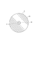
- FIG. 1 is a diagram showing a cross section of an optical fiber according to an embodiment.
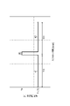
- FIG. 2 is a graph showing the radial distribution of the relative refractive index difference of the optical fiber according to the embodiment.
- FIG. 3 is a graph showing the relationship between the sooting time and deposition surface temperature.
- FIG. 4 is a graph showing the relationship between the deposition surface temperature difference and the bulk density difference.
- FIG. 5 is a graph showing the relationship between the bulk density difference and the ratio S2/S1.
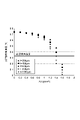
- FIG. 6 is a graph showing the relationship between bulk density difference and core portion chlorine concentration.
- An optical fiber having a refractive index profile of the ⁇ -th power type has an increased skirting compared to a step index (SI) type.
- SI step index
- An increase in the area of the skirt portion weakens the optical energy confinement, resulting in an increase in bending loss. Therefore, it is required to control the drooping and improve the bending loss characteristics.
- An object of the present disclosure is to provide an optical fiber and an optical fiber preform manufacturing method capable of improving bending loss characteristics.
- An optical fiber according to an embodiment of the present disclosure includes a core having an ⁇ power type refractive index distribution, and a clad provided around the core and having a refractive index n0 lower than the maximum refractive index of the core.
- 0 is the radial position of the central axis of the core
- r1 is the radial position where the slope of the radial distribution of the relative refractive index difference of the optical fiber with reference to the refractive index n0 is maximum negative
- the radial direction corresponding to the outer circumference of the clad is 8.5% or less.
- the ratio S2/S1 is 8.5% or less, and the degree of tailing is suppressed, so an increase in bending loss due to tailing can be suppressed. Therefore, bending loss characteristics can be improved.
- the ⁇ power type means that the refractive index distribution n(r) in the radial direction of the core changes from the center of the core to the radial distance r (0 ⁇ r ⁇ a) by the ⁇ multiplier shown in the following formula. It says that the shape is defined. In the formula, n1 is the maximum refractive index of the core, n0 is the refractive index of the clad, and ⁇ 1 is the maximum relative refractive index difference of the core.
- the bending loss at a wavelength of 1550 nm with a bending radius of 10 mm may be 7.5 dB/10 turns or less. In this case, ITU-T G. 657A series standards are satisfied.
- a method for manufacturing an optical fiber preform according to an embodiment of the present disclosure includes a step of depositing glass particles at a bulk density d1 to form a core portion having a refractive index distribution of the ⁇ power type; depositing particulates to form a cladding.
- the glass particles are deposited at a bulk density d0 higher than the bulk density d1, and then the glass particles are deposited at a bulk density d2 lower than the bulk density d0.
- the bulk density of the glass particles forming a certain portion is the average bulk density of the glass particles forming the portion.
- the bulk density d1 is the average bulk density of the glass particles forming the core.
- the bulk density d0 is the average bulk density of the glass particles forming the inner periphery of the clad.
- the bulk density d2 is the average bulk density of the glass fine particles forming the other part of the clad.
- the bulk density d0 may be made higher than the bulk densities d1 and d2 by controlling the temperature of the deposition surface on which the glass particles are deposited. In this case, the bulk density can be easily controlled.
- the number of burners used to generate the glass particles, the flow rate of the raw material gas supplied to the burners, the flow rate of the combustion gas supplied to the burners, and the traverse speed of the mandrel on which the glass particles are deposited. , and the number of revolutions of the mandrel may be controlled to control the deposition surface temperature. In this case, the bulk density can be easily controlled.
- the number of burners used when depositing the glass particles with bulk density d0 in the step of forming the cladding portion may be equal to or greater than the number of burners used in the step of forming the core portion. In this case, the deposition surface temperature is likely to rise rapidly. This improves the controllability of the hem.
- a difference between the bulk density d0 and the bulk density d1 and a difference between the bulk density d0 and the bulk density d2 may be 0.19 g/cm 3 or more and 1.4 g/cm 3 or less.
- this difference is 0.19 g/cm 3 or more, the ratio S2/S1 is set to 8.5% or less, and drooping can be suppressed.
- this difference is 1.4 g/cm 3 or less, the occurrence of strain between the inner peripheral portion of the clad portion and other portions is suppressed, and soot cracking and falling are suppressed.
- the step of forming the cladding portion may include a step of depositing glass particles so that the bulk density is d0 and the thickness is 200 ⁇ m or more and 1000 ⁇ m or less.
- the thickness is 200 ⁇ m or more, the additive in the core is suppressed from diffusing into the clad.
- the thickness is 1000 ⁇ m or less, chlorine molecules can permeate and diffuse from the outside of the cladding into the core during the dehydration process, thereby performing dehydration.
- FIG. 1 is a diagram showing a cross section of an optical fiber 1 according to an embodiment.
- an optical fiber 1 includes a core 10 and a clad 20 provided around the core 10 .
- the core 10 has a central axis C.
- Core 10 is made of, for example, silica glass containing germanium dioxide (GeO 2 ).
- the clad 20 is made of pure silica glass.
- the refractive index of the core 10 becomes higher than that of pure silica glass due to the addition of Ge.
- the core 10 has an ⁇ power type refractive index profile.
- the core 10 has the maximum refractive index n1 of the optical fiber 1 at the central axis C.
- the refractive index of clad 20 is smaller than the maximum refractive index n1 of core 10 .
- the clad 20 has a refractive index n0 smaller than the maximum refractive index n1 at least at the outermost periphery.
- a so-called skirting occurs, in which the refractive index gradually decreases outward from the boundary between the core 10 and the clad 20.
- the tailing is caused by the unavoidable diffusion of a dopant such as GeO 2 added to the core portion from the core portion to the clad portion during the manufacturing process of the optical fiber preform.
- the refractive index of the inner peripheral portion of the clad 20 becomes higher than the refractive index n0 due to the presence of the skirt.
- FIG. 2 is a graph showing the radial distribution of the relative refractive index difference of the optical fiber according to the embodiment.
- the horizontal axis indicates the radial position r, that is, the radial distance from the central axis C.
- FIG. The vertical axis indicates the relative refractive index difference ⁇ n with reference to the refractive index n0.
- ⁇ n1 is the relative refractive index difference of the maximum refractive index n1 with reference to the refractive index n0.
- the value S1 is a value obtained by integrating the relative refractive index difference ⁇ n(r) in the range of the radial position r from 0 to r1.
- the value S2 is a value obtained by integrating the relative refractive index difference ⁇ n(r) in the range of the radial position r from r1 to r2.
- the radial position r1 is the maximum negative relative refractive index difference between a certain radial position and a small radial distance in the range where the relative refractive index difference ⁇ n gradually decreases from the core 10 toward the clad 20. position.
- a radial position r1 is defined as the starting position of the hem.
- the radial position r1 corresponds to the boundary position between the core 10 and the clad 20 . Therefore, the radial distance from the central axis C to the radial position r1 can be regarded as the radius of the core 10.
- the optical fiber 1 conforms to ITU-T G. Designed to meet 657A series standards.
- the 657A series standard requires that the bending loss at a bending radius of 10 mm and a wavelength of 1550 nm be 7.5 dB/10 turns or less. According to knowledge obtained as a result of research by the present inventors, the bending loss characteristic improves as the ratio S2/S1 decreases.
- the MAC value in the case of the MAC value of 7.3, the bending loss satisfies the above standard by setting the ratio S2/S1 to 8.5% or less.
- the MAC value is a value obtained by dividing the mode field diameter (MFD) ( ⁇ m) at a wavelength of 1310 nm by the fiber cutoff wavelength ⁇ c ( ⁇ m).
- the optical fiber 1 is manufactured by drawing an optical fiber preform.
- the optical fiber preform of the optical fiber 1 is manufactured through steps of sooting, dehydration and sintering in order.
- the sooting process is carried out, for example, by a VAD (Vapor-phase Axial Deposition) method, a multi-layered OVD (Outside Vapor Deposition) method, or a multi-layered MMD method using multiple burners.
- the manufacturing method of the optical fiber preform includes a step of forming a glass particle deposited body (soot body) having a core portion to be the core 10 and a clad portion to be the clad 20 as a soot application step.
- the step of forming the glass particle deposit includes a step of depositing glass particles (soot) to form a core portion, and a step of depositing glass particles around the core portion to form a clad portion.
- An optical fiber preform manufacturing apparatus is used in the optical fiber preform manufacturing method.
- An apparatus for manufacturing an optical fiber preform used in the sooting step includes, for example, a reaction vessel having an exhaust device.
- the reaction vessel is equipped with multiple burners that are used to generate glass microparticles.
- the burner has multiple ports for blowing out gas.
- a combustion gas and a raw material gas are blown out from each port, and the raw material gas is hydrolyzed in an oxyhydrogen flame generated by combustion of the combustion gas to generate glass microparticles.
- the burners are oriented longitudinally toward the mandrel so as to deposit the produced glass particulates on the outer periphery of the mandrel.
- Combustion gases as used herein include, for example, hydrogen (H 2 ) and oxygen (O 2 ).
- the raw material gas contains, for example, silicon tetrachloride (SiCl 4 ), and germanium tetrachloride (GeCl 4 ) is added thereto as a refractive index adjuster.
- SiCl 4 silicon tetrachloride
- GeCl 4 germanium tetrachloride
- a holder that holds the mandrel is provided in the reaction vessel.
- the retainer is rotatable about an axis along the length of the mandrel.
- the holder is configured to be reciprocally movable (traverse) in the longitudinal direction of the mandrel, and is vertically reciprocated while rotating the mandrel.
- the manufacturing apparatus includes a control unit, and the control unit controls manufacturing conditions such as the number of burners used, the flow rate of the raw material gas, the flow rate of the combustion gas, the traverse speed of the mandrel, and the rotation speed of the mandrel.
- FIG. 3 is a graph showing the relationship between the sooting time and deposition surface temperature.
- the deposition surface temperature varies depending on the position within the deposition surface, here the maximum temperature within the deposition surface is defined as the deposition surface temperature.
- the bulk density of the glass fine particles is changed by changing the deposition surface temperature according to the sooting time. It is known that there is a strong correlation between the deposition surface temperature and the bulk density of glass particles.
- the core portion 110 is formed by depositing the glass particles at the deposition surface temperature T1 and the bulk density d1.
- the glass particles are deposited at a deposition surface temperature T0 and a bulk density d0 higher than the deposition surface temperature T1 and bulk density d1, respectively, so as to have a thickness of 200 ⁇ m or more and 1000 ⁇ m or less. Thereby, a region having a bulk density d0 is formed in the inner peripheral portion of the clad portion 120 . Since the bulk density d0 is higher than the bulk density d1 of the core portion 110, diffusion of Ge from the core portion 110 to the clad portion 120 is suppressed in each step of dehydration and sintering. If the thickness of the region of bulk density d0 is less than 200 ⁇ m, diffusion of Ge cannot be suppressed.
- the thickness of the region with bulk density d0 is greater than 1000 ⁇ m, chlorine (Cl 2 ) cannot permeate and diffuse from the outside of the cladding into the core during the dehydration process, making dehydration impossible. As a result, the transmission loss increases significantly.
- the glass particles are deposited at a deposition surface temperature T2 and a bulk density d2 lower than the deposition surface temperature T0 and the bulk density d0, respectively.
- the deposition surface temperature is controlled to make the bulk density d0 higher than the bulk densities d1 and d2 (d0>d1, d2).
- the bulk density difference ⁇ d which is the difference between the bulk density d0 and the bulk density d1 and the difference between the bulk density d0 and the bulk density d2, is 0.19 g/cm 3 or more and 0.8 g/cm 3 or less.
- the deposition surface temperatures T1 and T2 are equal to each other, and the bulk densities d1 and d2 are equal to each other, but they may be different from each other.
- the sooting step if the glass particles are deposited so that the bulk density d0 of the inner peripheral portion of the clad portion 120 is higher than the bulk density d1 of the core portion 110 and the bulk density d2 of the other portions of the clad portion 120, good.
- the number of burners used to generate the glass particles is controlled by controlling at least one of the speed and the number of revolutions of the mandrel.
- the number of burners used for depositing glass particles with bulk density d0 in the step of forming the cladding portion 120 is greater than or equal to the number of burners used in the step of forming the core portion 110.
- Table 1 is a table summarizing the simulation results of Experimental Examples 1 to 19.
- Table 1 shows the number of burners used in the step of forming the clad portion, the flow rate of GeCl 4 in the step of forming the core portion, the flow rate of SiCl 4 in the step of forming the clad portion, and the flow rate of SiCl 4 in the step of forming the clad portion.
- deposition surface temperature difference ⁇ T (° C.), bulk density difference ⁇ d (g/cm 3 ), ratio S2/S1 (%), MAC value, bending radius 10 mm bending loss (dB/10 turn) at a wavelength of 1550 nm.
- the deposition surface temperature difference ⁇ T is the difference between the deposition surface temperature T0 and the deposition surface temperatures T1 and T2, and the deposition surface temperatures T1 and T2 are assumed to be equal to each other.
- GeCl 4 flow rate, SiCl 4 flow rate, hydrogen flow rate, and traverse velocity are shown as relative values to those of Example 7.
- Each value of the deposition surface temperature difference ⁇ T (° C.) and the bulk density difference ⁇ d (g/cm 3 ) is based on the value of Experimental Example 7, and the difference from the value of Experimental Example 7 is shown.
- Experimental Examples 1 to 6 are examples showing how the hemline changes by changing the flow rate of GeCl 4 added to the core. According to the results of Experimental Examples 1 to 6, when the MAC value is 7.3, the bending loss satisfies the above standard by setting the ratio S2/S1 to 8.5% or less. Reducing the flow rate of GeCl 4 and decreasing the ratio S2/S1 can reduce the bending loss, but cannot increase the maximum refractive index of the core. Also, in general, the smaller the MAC value, the smaller the bending loss. Therefore, if the MAC value is small, the bending loss may satisfy the above standard even if the ratio S2/S1 exceeds 8.5%.
- the ratio S2/S1 is lowered by reducing the flow rate of SiCl 4 as the material gas in the step of forming the clad portion. Since SiCl 4 lowers the deposition surface temperature through an endothermic reaction, reducing its flow rate suppresses the decrease in deposition surface temperature. From the results of Experimental Examples 7, 14 to 16, it can be seen that the ratio S2/S1 is lowered by increasing the flow rate of the hydrogen gas, which is the combustion gas, in the step of forming the clad portion. From the results of Experimental Examples 7, 17 to 19, it can be seen that the ratio S2/S1 is lowered by slowing down the traverse speed in the step of forming the clad portion.
- the ratio S2/S1 in order to reduce the ratio S2/S1, the number of burners used in the step of forming the clad portion must be increased, the flow rate of the raw material gas can be decreased, the flow rate of the combustion gas can be increased, or the traverse speed can be decreased. is required. In addition, by combining these, the ratio S2/S1 can be finely adjusted.
- FIG. 4 is a graph showing the relationship between the deposition surface temperature difference ⁇ T and the bulk density difference ⁇ d. As shown in FIG. 4, there is a correlation between the deposition surface temperature difference ⁇ T and the bulk density difference ⁇ d. As the deposition surface temperature difference ⁇ T increases, the bulk density difference ⁇ d increases.
- FIG. 5 is a graph showing the relationship between bulk density difference and S2/S1.
- the flow rate of GeCl 4 in the process of forming the core portion is the same (one time).
- the ratio S2/S1 decreases and the bending loss characteristic improves. If the bulk density difference ⁇ d is less than 0.19 g/cm 3 , the ratio S2/S1 becomes greater than 8.5%, and the bending loss does not satisfy the above standard.
- FIG. 6 is a graph showing the relationship between bulk density difference and core portion chlorine concentration.
- FIG. 6 shows the relationship between the bulk density difference and the core portion chlorine concentration when the thickness of the bulk density d0 region is 200 ⁇ m, 400 ⁇ m, 600 ⁇ m, 800 ⁇ m, and 1000 ⁇ m.
- the core portion chlorine concentration is a relative concentration when the chlorine concentration in the outermost peripheral portion of the clad portion is regarded as 1.
- the bulk density difference ⁇ d is 0.19 g/cm 3 or more and 0.8 g/cm 3 or less, there is almost no change in the core portion chlorine concentration.
- the chlorine molecules are diffused from the outside of the clad to the core with little hindrance. Thereby, it is suppressed that dehydration becomes impossible in the dehydration process.
- the thickness of the region having the bulk density d0 in the inner peripheral portion of the clad portion can be in the range of 200 ⁇ m or more and 1000 ⁇ m or less.
- the chlorine concentration in the core portion is adjusted to the required chlorine concentration (0.33%) by setting the thickness of the bulk density d0 region to a range of 200 ⁇ m or more and 600 ⁇ m or less. You can keep more than that.
- the bulk density difference ⁇ d is 0.19 g/cm 3 or more and 1.2 g/cm 3 or less
- the thickness of the bulk density d0 region is within the range of 200 ⁇ m or more and 1000 ⁇ m or less.
- the core 10 has an ⁇ power type refractive index distribution, the ratio S2/S1 is 8.5% or less, and the tailing is suppressed. It is possible to suppress the increase in bending loss due to
- a region having a higher bulk density than others is formed in the inner peripheral portion of the clad portion 120 . Therefore, diffusion of Ge added to the core portion 110 to the clad portion 120 is suppressed. As a result, the occurrence of skirting is suppressed, so that the bending loss characteristic of the optical fiber 1 can be improved.
- the bulk density of the outer peripheral portion of the core portion is made higher than that of the others, thereby suppressing the occurrence of skirting.
- the bulk density of the inner peripheral portion of the clad portion 120 to which Ge is not added is increased, soot cracking and falling can be suppressed. Therefore, productivity is improved.
- Reference Signs List 1 Optical fiber 10 Core 20 Clad 110 Core portion 120 Clad portion C Central axis d0 Bulk density d1 Bulk density d2 Bulk density ⁇ d Bulk density difference ⁇ n Relative refractive index difference r1
- Radial position r2 radial position S1: integrated value of the relative refractive index difference in the radial position range from 0 to r1
- S2 integrated value of the relative refractive index difference in the radial position range from r1 to r2
- T0 deposition surface temperature T1 Deposition surface temperature T2 Deposition surface temperature ⁇ T Deposition surface temperature difference
Abstract
光ファイバは、α乗型の屈折率分布を有するコアと、コアの周囲に設けられ、コアの最大屈折率よりも低い屈折率n0を有するクラッドと、を備える。コアの中心軸の径方向位置を0、屈折率n0を基準とした光ファイバの比屈折率差の径方向分布の傾きが負に最大となる径方向位置をr1、クラッドの外周部にあたる径方向位置をr2としたとき、比屈折率差を径方向位置が0からr1の範囲で積分した値S1と、比屈折率差を径方向位置がr1からr2の範囲で積分した値S2との比S2/S1は、8.5%以下である。
Description
本開示は、光ファイバ及び光ファイバ母材の製造方法に関する。
本出願は、2021年2月25日出願の日本出願第2021-028378号に基づく優先権を主張し、前記日本出願に記載された全ての記載内容を援用するものである。
本出願は、2021年2月25日出願の日本出願第2021-028378号に基づく優先権を主張し、前記日本出願に記載された全ての記載内容を援用するものである。
特許文献1及び特許文献2には、コアとクラッドとの境界から外側に向かって屈折率がなだらかに減少していく、いわゆる、すそだれが発生しているシングルモード光ファイバ(SMF)が記載されている。また、特許文献2には、コアの外周部の嵩密度をクラッドより高くすることが記載されている。
本開示の光ファイバは、α乗型の屈折率分布を有するコアと、コアの周囲に設けられ、コアの最大屈折率よりも低い屈折率n0を有するクラッドと、を備える。コアの中心軸の径方向位置を0、屈折率n0を基準とした光ファイバの比屈折率差の径方向分布の傾きが負に最大となる径方向位置をr1、クラッドの外周部にあたる径方向位置をr2としたとき、比屈折率差を径方向位置が0からr1の範囲で積分した値S1と、比屈折率差を径方向位置がr1からr2の範囲で積分した値S2との比S2/S1は、8.5%以下である。
本開示の光ファイバ母材の製造方法は、ガラス微粒子を嵩密度d1で堆積させてα乗型の屈折率分布を有するコア部を形成する工程と、コア部の周囲にガラス微粒子を堆積させてクラッド部を形成する工程と、を含む。クラッド部を形成する工程は、ガラス微粒子を嵩密度d1よりも高い嵩密度d0で堆積させた後、ガラス微粒子を嵩密度d0よりも低い嵩密度d2で堆積させる。
[本開示が解決しようとする課題]
α乗型の屈折率分布を持つ光ファイバでは、すそだれがステップインデックス(SI)型と比べて増加する。すそだれ部の面積が増加すると、光エネルギーの閉じ込め力が弱くなるため、曲げ損失が増加する。そこで、すそだれの制御を行い、曲げ損失特性を向上させることが求められている。
α乗型の屈折率分布を持つ光ファイバでは、すそだれがステップインデックス(SI)型と比べて増加する。すそだれ部の面積が増加すると、光エネルギーの閉じ込め力が弱くなるため、曲げ損失が増加する。そこで、すそだれの制御を行い、曲げ損失特性を向上させることが求められている。
本開示は、曲げ損失特性を向上させることができる光ファイバ及び光ファイバ母材の製造方法を提供することを目的とする。
[本開示の効果]
本開示によれば、曲げ損失特性を向上させることができる光ファイバ及び光ファイバ母材の製造方法を提供することができる。
本開示によれば、曲げ損失特性を向上させることができる光ファイバ及び光ファイバ母材の製造方法を提供することができる。
[本開示の実施形態の説明]
最初に本開示の実施態様を列記して説明する。本開示の一実施形態に係る光ファイバは、α乗型の屈折率分布を有するコアと、コアの周囲に設けられ、コアの最大屈折率よりも低い屈折率n0を有するクラッドと、を備える。コアの中心軸の径方向位置を0、屈折率n0を基準とした光ファイバの比屈折率差の径方向分布の傾きが負に最大となる径方向位置をr1、クラッドの外周部にあたる径方向位置をr2としたとき、比屈折率差を径方向位置が0からr1の範囲で積分した値S1と、比屈折率差を径方向位置がr1からr2の範囲で積分した値S2との比S2/S1は、8.5%以下である。
最初に本開示の実施態様を列記して説明する。本開示の一実施形態に係る光ファイバは、α乗型の屈折率分布を有するコアと、コアの周囲に設けられ、コアの最大屈折率よりも低い屈折率n0を有するクラッドと、を備える。コアの中心軸の径方向位置を0、屈折率n0を基準とした光ファイバの比屈折率差の径方向分布の傾きが負に最大となる径方向位置をr1、クラッドの外周部にあたる径方向位置をr2としたとき、比屈折率差を径方向位置が0からr1の範囲で積分した値S1と、比屈折率差を径方向位置がr1からr2の範囲で積分した値S2との比S2/S1は、8.5%以下である。
この光ファイバでは、比S2/S1は、8.5%以下であり、すそだれの程度が抑制されているので、すそだれによる曲げ損失の増加が抑制できる。よって、曲げ損失特性を向上させることができる。なお、α乗型とは、コアの径方向の屈折率分布n(r)が、コアの中心から半径方向の距離r(0≦r≦a)に対して、下記式に示すα乗数によりその形状が規定されることを言う。なお、式の、n1はコアの最大屈折率、n0はクラッドの屈折率、Δ1はコアの最大比屈折率差を示す。


曲げ半径10mmでの波長1550nmにおける曲げ損失は、7.5dB/10turn以下であってもよい。この場合、ITU-T G.657Aシリーズの規格が満足される。
本開示の一実施形態に係る光ファイバ母材の製造方法は、ガラス微粒子を嵩密度d1で堆積させてα乗型の屈折率分布を有するコア部を形成する工程と、コア部の周囲にガラス微粒子を堆積させてクラッド部を形成する工程と、を含む。クラッド部を形成する工程は、ガラス微粒子を嵩密度d1よりも高い嵩密度d0で堆積させた後、ガラス微粒子を嵩密度d0よりも低い嵩密度d2で堆積させる。ここで、ある部分を形成しているガラス微粒子の嵩密度は、当該部分を形成しているガラス微粒子の平均嵩密度とする。例えば、嵩密度d1は、コア部を形成しているガラス微粒子の平均嵩密度である。嵩密度d0は、クラッド部の内周部を形成しているガラス微粒子の平均嵩密度である。嵩密度d2は、クラッド部の他の部分を形成しているガラス微粒子の平均嵩密度である。
この光ファイバ母材の製造方法では、クラッド部の内周部に嵩密度が他よりも高い領域が形成される。よって、コア部の添加物がクラッド部に拡散することが抑制される。これにより、すそだれが抑制されるので、曲げ損失特性を向上させることができる。
クラッド部を形成する工程は、ガラス微粒子が堆積される堆積面温度を制御することにより、嵩密度d0を嵩密度d1及び嵩密度d2よりも高くしてもよい。この場合、嵩密度を容易に制御することができる。
クラッド部を形成する工程では、ガラス微粒子の生成に使用されるバーナの本数、バーナに供給される原料ガスの流量、バーナに供給される燃焼ガスの流量、ガラス微粒子が堆積されるマンドレルのトラバース速度、及び、マンドレルの回転数のうち、少なくとも一つを制御することにより、堆積面温度を制御してもよい。この場合、嵩密度を容易に制御することができる。
クラッド部を形成する工程でガラス微粒子を嵩密度d0で堆積させる際に使用されるバーナの本数は、コア部を形成する工程で使用されるバーナの本数以上であってもよい。この場合、堆積面温度を急激に上げ易い。これにより、すそだれの制御性が向上する。
嵩密度d0と嵩密度d1との差、及び嵩密度d0と嵩密度d2との差が、それぞれ0.19g/cm3以上1.4g/cm3以下であってもよい。この差が0.19g/cm3以上であることにより、比S2/S1を8.5%以下とし、すそだれを抑制することができる。この差が1.4g/cm3以下であることにより、クラッド部の内周部と他の部分との間に歪が生じることが抑制され、スス割れや落下が起こることが抑制される。
クラッド部を形成する工程は、ガラス微粒子を嵩密度d0で厚さが200μm以上1000μm以下となるように堆積させる工程を含んでもよい。厚さが200μm以上であることにより、コア部の添加物がクラッド部に拡散することが抑制される。厚さが1000μm以下であることにより、脱水工程において塩素分子をクラッド部の外側からコア部に浸透及び拡散させ、脱水を行うことができる。
[本開示の実施形態の詳細]
本開示の光ファイバ及び光ファイバ母材の製造方法の具体例を、以下に図面を参照しつつ説明する。なお、本発明はこれらの例示に限定されるものではなく、請求の範囲によって示され、請求の範囲と均等の意味及び範囲内でのすべての変更が含まれることが意図される。図面の説明において同一の要素には同一の符号を付し、重複する説明を省略する。
本開示の光ファイバ及び光ファイバ母材の製造方法の具体例を、以下に図面を参照しつつ説明する。なお、本発明はこれらの例示に限定されるものではなく、請求の範囲によって示され、請求の範囲と均等の意味及び範囲内でのすべての変更が含まれることが意図される。図面の説明において同一の要素には同一の符号を付し、重複する説明を省略する。
図1は、実施形態に係る光ファイバ1の断面を示す図である。図1に示されるように、光ファイバ1は、コア10と、コア10の周囲に設けられたクラッド20と、を備える。コア10は、中心軸Cを有している。コア10は、たとえば、二酸化ゲルマニウム(GeO2)を含むシリカガラスからなる。クラッド20は、純シリカガラスからなる。コア10の屈折率は、Geの添加によって純シリカガラスよりも高くなる。光ファイバ1では、コア10はα乗型の屈折率分布を有している。コア10は、中心軸Cにおいて、光ファイバ1の最大屈折率n1を有する。
クラッド20の屈折率は、コア10の最大屈折率n1よりも小さい。クラッド20は、少なくとも最外周部において、最大屈折率n1よりも小さい屈折率n0を有する。光ファイバ1では、コア10とクラッド20との境界から外側に向かって屈折率がなだらかに減少していく、いわゆる、すそだれが発生している。すそだれは、光ファイバ母材の製造過程において、コア部に添加されたGeO2等の添加物が、コア部からクラッド部へ不可避的に拡散することにより発生する。クラッド20の内周部の屈折率は、すそだれの存在によって屈折率n0よりも大きくなる。
図2は、実施形態に係る光ファイバの比屈折率差の径方向分布を示すグラフである。横軸は、径方向位置r、すなわち、中心軸Cからの径方向距離を示す。縦軸は、屈折率n0を基準とした比屈折率差Δnを示す。Δn1は、屈折率n0を基準とした最大屈折率n1の比屈折率差である。比屈折率差Δnの径方向分布の傾きが負に最大となる径方向位置をr1、クラッド20の外周の径方向位置をr2としたとき、以下の式で表される値S1と値S2との比S2/S1は、8.5%以下である。
値S1は、比屈折率差Δn(r)を径方向位置rが0からr1の範囲で積分した値である。値S2は、比屈折率差Δn(r)を径方向位置rがr1からr2の範囲で積分した値である。径方向位置r1は、比屈折率差Δnがコア10からクラッド20に向かって徐々に減少する範囲において、ある径方向位置から微小径方向距離の間に変化した比屈折率差が負に最大になる位置である。径方向位置r1は、すそだれの開始位置として規定される。つまり、径方向位置r1は、コア10とクラッド20の境界位置に対応する。よって、中心軸Cから径方向位置r1までの径方向距離は、コア10の半径とみなせる。
比S2/S1を用いてすそだれの度合いを評価することで、光ファイバ1は、ITU-T G.657Aシリーズの規格を満たすように設計されている。ITU-T G.657Aシリーズの規格では、曲げ半径10mmでの波長1550nmにおける曲げ損失を7.5dB/10turn以下とすることが求められる。本発明者らが研究の結果として得た知見によると、比S2/S1が小さくなるほど、曲げ損失特性が向上する。MAC値を用いて整理したところ、MAC値7.3の場合、比S2/S1を8.5%以下にすることで、曲げ損失が上記規格を満たす。MAC値は、波長1310nmにおけるモードフィールド径(MFD)(μm)をファイバカットオフ波長λc(μm)で割った値である。
光ファイバ1は、光ファイバ母材を線引きすることにより製造される。光ファイバ1の光ファイバ母材は、スス付け、脱水及び焼結の各工程を順に経て製造される。スス付け工程は、たとえば、VAD(Vapor-phase Axial Deposition)法、多層付け法であるOVD(Outside Vapor Deposition)法、または、複数本バーナによる多層付け法であるMMD法による。光ファイバ母材の製造方法は、スス付け工程として、コア10となるコア部、及び、クラッド20となるクラッド部を有するガラス微粒子堆積体(スス体)を形成する工程を含む。ガラス微粒子堆積体を形成する工程は、ガラス微粒子(スス)を堆積させてコア部を形成する工程と、コア部の周囲にガラス微粒子を堆積させてクラッド部を形成する工程と、を含む。
光ファイバ母材の製造方法では、光ファイバ母材の製造装置が用いられる。スス付け工程で用いられる光ファイバ母材の製造装置は、たとえば、排気装置を有する反応容器を備える。反応容器には、ガラス微粒子の生成に使用される複数のバーナが取り付けられている。バーナは、ガスを吹き出すための複数のポートを有している。各ポートそれぞれから燃焼ガス及び原料ガスを吹き出し、燃焼ガスの燃焼により生じる酸水素火炎中において原料ガスを加水分解反応させて、ガラス微粒子を生成する。バーナは、生成したガラス微粒子をマンドレルの外周上に堆積させるように、マンドレルに向けて縦方向に配置されている。
ここで用いる燃焼ガスには、たとえば水素(H2)及び酸素(O2)が含まれる。また、原料ガスには、たとえば四塩化ケイ素(SiCl4)が含まれ、そこに四塩化ゲルマニウム(GeCl4)が屈折率調整剤として添加される。原料ガスとして四塩化ケイ素と四塩化ゲルマニウムを用いた場合、シリカ(SiO2)及びGeO2を主成分とするガラス微粒子がバーナ火炎中で生成される。
反応容器内にはマンドレルを保持する保持具が設けられている。保持具は、マンドレルの長手方向に沿った軸を中心として回動可能である。また、保持具は、マンドレルの長手方向に往復移動(トラバース)可能なように構成されており、マンドレルを回転しながら、上下方向に往復移動させる。製造装置は、制御部を備え、制御部は、たとえば、バーナの使用本数、原料ガスの流量、燃焼ガスの流量、マンドレルのトラバース速度、マンドレルの回転数等の製造条件を制御する。
図3は、スス付け時間と堆積面温度との関係を示すグラフである。堆積面温度は、堆積面内の位置によって異なるが、ここでは、堆積面内の最高温度を堆積面温度とする。図3に示されるように、スス付け工程では、スス付け時間に応じて堆積面温度を変化させることにより、ガラス微粒子の嵩密度を変化させている。堆積面温度と、ガラス微粒子の嵩密度との間には強い相関関係があることが知られている。コア部110を形成する工程では、堆積面温度T1及び嵩密度d1でガラス微粒子を堆積させることにより、コア部110を形成する。
クラッド部120を形成する工程では、まず、ガラス微粒子を堆積面温度T1及び嵩密度d1よりもそれぞれ高い堆積面温度T0及び嵩密度d0で、厚さが200μm以上1000μm以下となるように堆積させる。これにより、クラッド部120の内周部に、嵩密度d0の領域が形成される。嵩密度d0は、コア部110の嵩密度d1よりも高いので、脱水及び焼結の各工程において、コア部110からクラッド部120にGeが拡散することが抑制される。嵩密度d0の領域の厚さが200μmよりも薄いと、Geの拡散を抑制することができなくなる。嵩密度d0の領域の厚さが1000μmよりも厚いと、脱水工程において、塩素(Cl2)をクラッド部の外側からコア部に浸透及び拡散させることができず、脱水不可になる。その結果、伝送損失が大きく増加してしまう。
続いて、ガラス微粒子を堆積面温度T0及び嵩密度d0よりもそれぞれ低い堆積面温度T2及び嵩密度d2で堆積させる。このように、クラッド部120を形成する工程は、堆積面温度を制御することにより、嵩密度d0を嵩密度d1及び嵩密度d2よりも高くする(d0>d1,d2)。嵩密度d0と嵩密度d1との差、及び嵩密度d0と嵩密度d2との差である嵩密度差Δdは、それぞれ0.19g/cm3以上0.8g/cm3以下とされる。ここでは、堆積面温度T1,T2が互いに同等であり、嵩密度d1,d2が互いに同等であるが、それぞれ互いに異なっていてもよい。スス付け工程では、クラッド部120の内周部の嵩密度d0が、コア部110の嵩密度d1及びクラッド部120の他の部分の嵩密度d2よりも高くなるようにガラス微粒子を堆積させればよい。
クラッド部120を形成する工程では、ガラス微粒子の生成に使用されるバーナの本数、バーナに供給される原料ガスの流量、バーナに供給される燃焼ガスの流量、ガラス微粒子が堆積されるマンドレルのトラバース速度、及び、マンドレルの回転数のうち、少なくとも一つを制御することにより、堆積面温度を制御する。たとえば、クラッド部120を形成する工程で、ガラス微粒子を嵩密度d0で堆積させる際に使用されるバーナの本数は、コア部110を形成する工程で使用されるバーナの本数以上とされる。バーナ本数が増加することにより、堆積面温度を急激に上げることができるので、すそだれの制御性が向上する。
次に、クラッド部120の内周部に嵩密度d0の領域を形成する際の製造条件を変更した場合のシミュレーション結果について説明する。表1は、実験例1から19のシミュレーション結果をまとめた表である。表1では、クラッド部を形成する工程で使用したバーナの本数、コア部を形成する工程でのGeCl4の流量、クラッド部を形成する工程でのSiCl4の流量、クラッド部を形成する工程での水素流量、クラッド部を形成する工程でのトラバース速度、堆積面温度差ΔT(℃)、嵩密度差Δd(g/cm3)、比S2/S1(%)、MAC値、曲げ半径10mmでの波長1550nmにおける曲げ損失(dB/10turn)が示されている。堆積面温度差ΔTは、堆積面温度T0と堆積面温度T1,T2との差であり、堆積面温度T1,T2が互いに同等であるものとしている。GeCl4の流量、SiCl4の流量、水素流量、及び、トラバース速度は、実験例7の値に対する相対値として示されている。堆積面温度差ΔT(℃)、及び、嵩密度差Δd(g/cm3)の各値は、実験例7の値を基準とし、実験例7の値との差で示されている。

実験例1から4、9、10、12から15、19では、比S2/S1が8.5%以下であり、曲げ損失が上記規格を満たす。実験例5から8、11、16から18では、比S2/S1が8.5%を超え、曲げ損失が上記規格を満たさない。
実験例1から6は、コアに添加するGeCl4の流量を変更することにより、すそだれがどのように変化するかを示す例である。実験例1から6の結果によれば、MAC値が7.3の場合、比S2/S1を8.5%以下とすることにより、曲げ損失が上記規格を満たすことが分かる。GeCl4の流量を少なくし、比S2/S1を小さくするほど、曲げ損失を小さくすることはできるが、コアの最大屈折率を上げることはできない。また、一般にMAC値が小さくなるほど、曲げ損失が小さくなる。したがって、MAC値が小さくなれば、比S2/S1が8.5%を超えても、曲げ損失が上記規格を満たす場合がある。
実験例1、7から10の結果から、クラッド部を形成する工程で使用したバーナの本数を増やすことにより、比S2/S1が低下することがわかる。また、バーナの本数を3本以上とすると、曲げ損失が上記規格を満たすことがわかる。バーナの本数を増やすことにより、堆積面をむらなく加熱することができる。
実験例7,11から13の結果から、クラッド部を形成する工程において、原料ガスであるSiCl4の流量を減らすことにより、比S2/S1が低下することがわかる。SiCl4は、吸熱反応により堆積面温度を低下させるので、その流量を減らすと堆積面温度の低下が抑制される。実験例7,14から16の結果から、クラッド部を形成する工程において、燃焼ガスである水素ガスの流量を増やすことにより、比S2/S1が低下することがわかる。実験例7,17から19の結果から、クラッド部を形成する工程において、トラバース速度を遅くすることにより、比S2/S1が低下することがわかる。
以上の結果から、比S2/S1を小さくするには、クラッド部を形成する工程で用いられるバーナの本数の増加、原料ガスの流量の減少、燃焼ガスの流量の増加、又は、トラバース速度の減少が必要である。加えて、これらを複合することにより、比S2/S1を微調整することができる。
図4は、堆積面温度差ΔTと嵩密度差Δdとの関係を示すグラフである。図4に示されるように、堆積面温度差ΔTと嵩密度差Δdとの間には相関関係がある。堆積面温度差ΔTが大きくなるほど、嵩密度差Δdが大きくなっている。
図5は、嵩密度差とS2/S1との関係を示すグラフである。なお、コア部を形成する工程でのGeCl4の流量は、同じ(1倍)としている。図5に示されるように、嵩密度差Δdと比S2/S1との間には相関関係がある。嵩密度差Δdが大きくなるほど、と比S2/S1が小さくなり、曲げ損失特性が向上する。嵩密度差Δdが0.19g/cm3より小さいと、比S2/S1が8.5%より大きくなり、曲げ損失が上記規格を満たさなくなる。
図6は、嵩密度差とコア部塩素濃度との関係を示すグラフである。図6では、嵩密度d0の領域の厚さを200μm、400μm、600μm、800μm、及び、1000μmとした場合のそれぞれについて、嵩密度差とコア部塩素濃度との関係が示されている。コア部塩素濃度は、クラッド部の最外周部の塩素濃度を1とみなしたときの相対濃度である。嵩密度差Δdが0.19g/cm3以上0.8g/cm3以下のとき、コア部塩素濃度にほとんど変化がない。つまり、塩素分子がほとんど阻害されることなく、クラッド部の外側からコア部へ拡散している。これにより、脱水工程において脱水不可になることが抑制される。
上述のように、クラッド部の内周部における嵩密度d0の領域の厚さは、200μm以上1000μm以下の範囲とすることができる。嵩密度差Δdが1.4g/cm3のときは、嵩密度d0の領域の厚さを200μm以上600μm以下の範囲とすることで、コア部の塩素濃度を必要塩素濃度(0.33%)以上に保つことができる。嵩密度差Δdが0.19g/cm3以上1.2g/cm3以下のときは、嵩密度d0の領域の厚さは、200μm以上1000μm以下の範囲で問題ない。
以上説明したように、光ファイバ1では、コア10がα乗型の屈折率分布を有し、比S2/S1は、8.5%以下であり、すそだれが抑制されているので、すそだれによる曲げ損失の増加が抑制できる。
光ファイバ母材の製造方法では、クラッド部120の内周部に嵩密度が他よりも高い領域が形成される。よって、コア部110に添加されたGeがクラッド部120に拡散することが抑制される。この結果、すそだれの発生が抑制されるので、光ファイバ1の曲げ損失特性を向上させることができる。
特許文献2に記載の光ファイバ母材の製造方法では、コア部の外周部の嵩密度を他より高くすることで、すそだれの発生を抑制している。しかしながら、コア部にはGeが添加されているため、嵩密度を高くすると、歪が生じ易く、スス割れや落下が起こる可能性がある。これに対し、本実施形態の製造方法では、Geが添加されていないクラッド部120の内周部の嵩密度を高くするので、スス割れや落下を抑制することができる。よって、生産性が向上する。
1…光ファイバ
10…コア
20…クラッド
110…コア部
120…クラッド部
C…中心軸
d0…嵩密度
d1…嵩密度
d2…嵩密度
Δd…嵩密度差
Δn…比屈折率差
r1…径方向位置
r2…径方向位置
S1…比屈折率差を径方向位置が0からr1の範囲で積分した値
S2…比屈折率差を径方向位置がr1からr2の範囲で積分した値
T0…堆積面温度
T1…堆積面温度
T2…堆積面温度
ΔT…堆積面温度差
10…コア
20…クラッド
110…コア部
120…クラッド部
C…中心軸
d0…嵩密度
d1…嵩密度
d2…嵩密度
Δd…嵩密度差
Δn…比屈折率差
r1…径方向位置
r2…径方向位置
S1…比屈折率差を径方向位置が0からr1の範囲で積分した値
S2…比屈折率差を径方向位置がr1からr2の範囲で積分した値
T0…堆積面温度
T1…堆積面温度
T2…堆積面温度
ΔT…堆積面温度差
Claims (8)
- α乗型の屈折率分布を有するコアと、
前記コアの周囲に設けられ、前記コアの最大屈折率よりも低い屈折率n0を有するクラッドと、を備える光ファイバであって、
前記コアの中心軸の径方向位置を0、前記屈折率n0を基準とした前記光ファイバの比屈折率差の径方向分布の傾きが負に最大となる径方向位置をr1、前記クラッドの外周部にあたる径方向位置をr2としたとき、前記比屈折率差を径方向位置が0からr1の範囲で積分した値S1と、前記比屈折率差を径方向位置がr1からr2の範囲で積分した値S2との比S2/S1は、8.5%以下である、
光ファイバ。 - 曲げ半径10mmでの波長1550nmにおける曲げ損失は、7.5dB/10turn以下である、
請求項1に記載の光ファイバ。 - ガラス微粒子を嵩密度d1で堆積させてα乗型の屈折率分布を有するコア部を形成する工程と、
前記コア部の周囲にガラス微粒子を堆積させてクラッド部を形成する工程と、を含み、
前記クラッド部を形成する工程は、ガラス微粒子を前記嵩密度d1よりも高い嵩密度d0で堆積させた後、ガラス微粒子を前記嵩密度d0よりも低い嵩密度d2で堆積させる、
光ファイバ母材の製造方法。 - 前記クラッド部を形成する工程は、ガラス微粒子が堆積される堆積面温度を制御することにより、前記嵩密度d0を前記嵩密度d1及び前記嵩密度d2よりも高くする、
請求項3に記載の光ファイバ母材の製造方法。 - 前記クラッド部を形成する工程では、ガラス微粒子の生成に使用されるバーナの本数、前記バーナに供給される原料ガスの流量、前記バーナに供給される燃焼ガスの流量、ガラス微粒子が堆積されるマンドレルのトラバース速度、及び、前記マンドレルの回転数のうち、少なくとも一つを制御することにより、前記堆積面温度を制御する、
請求項4に記載の光ファイバ母材の製造方法。 - 前記クラッド部を形成する工程でガラス微粒子を前記嵩密度d0で堆積させる際に使用されるバーナの本数は、前記コア部を形成する工程で使用されるバーナの本数以上である、
請求項3から請求項5のいずれか一項に記載の光ファイバ母材の製造方法。 - 前記嵩密度d0と前記嵩密度d1との差、及び前記嵩密度d0と前記嵩密度d2との差が、それぞれ0.19g/cm3以上1.4g/cm3以下である、
請求項3から請求項6のいずれか一項に記載の光ファイバ母材の製造方法。 - 前記クラッド部を形成する工程は、ガラス微粒子を前記嵩密度d0で厚さが200μm以上1000μm以下となるように堆積させる工程を含む、
請求項3から請求項7のいずれか一項に記載の光ファイバ母材の製造方法。
Priority Applications (1)
| Application Number | Priority Date | Filing Date | Title |
|---|---|---|---|
| JP2023502460A JPWO2022181648A1 (ja) | 2021-02-25 | 2022-02-22 |
Applications Claiming Priority (2)
| Application Number | Priority Date | Filing Date | Title |
|---|---|---|---|
| JP2021028378 | 2021-02-25 | ||
| JP2021-028378 | 2021-02-25 |
Publications (1)
| Publication Number | Publication Date |
|---|---|
| WO2022181648A1 true WO2022181648A1 (ja) | 2022-09-01 |
Family
ID=83049019
Family Applications (1)
| Application Number | Title | Priority Date | Filing Date |
|---|---|---|---|
| PCT/JP2022/007405 WO2022181648A1 (ja) | 2021-02-25 | 2022-02-22 | 光ファイバ及び光ファイバ母材の製造方法 |
Country Status (2)
| Country | Link |
|---|---|
| JP (1) | JPWO2022181648A1 (ja) |
| WO (1) | WO2022181648A1 (ja) |
Citations (6)
| Publication number | Priority date | Publication date | Assignee | Title |
|---|---|---|---|---|
| JPS6374931A (ja) * | 1986-09-16 | 1988-04-05 | Sumitomo Electric Ind Ltd | 単一モ−ド光フアイバ用母材の製造方法 |
| JPH038737A (ja) * | 1989-06-06 | 1991-01-16 | Shin Etsu Chem Co Ltd | 光ファイバ用母材の製造方法 |
| JPH09230145A (ja) * | 1996-02-21 | 1997-09-05 | Sumitomo Electric Ind Ltd | プラスティック光ファイバ母材及びその製造方法 |
| JP2001180959A (ja) * | 1999-12-21 | 2001-07-03 | Sumitomo Electric Ind Ltd | 光ファイバ母材の製造方法 |
| JP2008197239A (ja) * | 2007-02-09 | 2008-08-28 | Sekisui Chem Co Ltd | ポリ塩化ビニル系樹脂製光伝送体の製造方法 |
| US20140174133A1 (en) * | 2012-12-20 | 2014-06-26 | Corning Incorporated | Methods for forming optical fiber preforms with selective diffusion layers |
-
2022
- 2022-02-22 JP JP2023502460A patent/JPWO2022181648A1/ja active Pending
- 2022-02-22 WO PCT/JP2022/007405 patent/WO2022181648A1/ja active Application Filing
Patent Citations (6)
| Publication number | Priority date | Publication date | Assignee | Title |
|---|---|---|---|---|
| JPS6374931A (ja) * | 1986-09-16 | 1988-04-05 | Sumitomo Electric Ind Ltd | 単一モ−ド光フアイバ用母材の製造方法 |
| JPH038737A (ja) * | 1989-06-06 | 1991-01-16 | Shin Etsu Chem Co Ltd | 光ファイバ用母材の製造方法 |
| JPH09230145A (ja) * | 1996-02-21 | 1997-09-05 | Sumitomo Electric Ind Ltd | プラスティック光ファイバ母材及びその製造方法 |
| JP2001180959A (ja) * | 1999-12-21 | 2001-07-03 | Sumitomo Electric Ind Ltd | 光ファイバ母材の製造方法 |
| JP2008197239A (ja) * | 2007-02-09 | 2008-08-28 | Sekisui Chem Co Ltd | ポリ塩化ビニル系樹脂製光伝送体の製造方法 |
| US20140174133A1 (en) * | 2012-12-20 | 2014-06-26 | Corning Incorporated | Methods for forming optical fiber preforms with selective diffusion layers |
Also Published As
| Publication number | Publication date |
|---|---|
| JPWO2022181648A1 (ja) | 2022-09-01 |
Similar Documents
| Publication | Publication Date | Title |
|---|---|---|
| JP7190236B2 (ja) | フッ素および塩素が共ドープされたコア領域を有する低損失光ファイバ | |
| EP2726422B1 (en) | Methods for producing optical fiber preforms with low index trenches | |
| US20140161406A1 (en) | Method of manufacturing optical fiber preform and optical fiber | |
| WO2011108639A1 (ja) | 石英多孔質体の製造方法、光ファイバ母材の製造方法、石英多孔質体、及び光ファイバ母材 | |
| JP6513796B2 (ja) | 一工程フッ素トレンチ及びオーバークラッドを有する光ファイバプリフォームの作製方法 | |
| US11577984B2 (en) | Method for manufacturing optical fiber preform, optical fiber preform, method for manufacturing optical fiber, and optical fiber | |
| JP5799903B2 (ja) | シングルモード光ファイバ | |
| JP3782923B2 (ja) | 分散制御光ファイバ | |
| WO2022181648A1 (ja) | 光ファイバ及び光ファイバ母材の製造方法 | |
| CN114057388A (zh) | 光纤预制棒的制造方法、光纤预制棒及光纤 | |
| JP4540923B2 (ja) | 光ファイバの製造方法および光ファイバ母材の製造方法 | |
| JP3738510B2 (ja) | 光ファイバ及びその製造方法 | |
| JP4455740B2 (ja) | 光ファイバ用プリフォームの製造方法 | |
| JP7455079B2 (ja) | 光ファイバ | |
| JPH0764578B2 (ja) | シングルモード光フアイバ用母材の製造方法 | |
| JP7286587B2 (ja) | 光ファイバ母材 | |
| WO2007054961A2 (en) | Optical fiber preform having large size soot porous body and its method of preparation | |
| CN113552666A (zh) | 光纤 | |
| JPH1053429A (ja) | 光ファイバ用母材およびその製造方法 | |
| US6928841B2 (en) | Optical fiber preform manufacture using improved VAD | |
| AU647051B2 (en) | Method for making a preform doped with a metal oxide | |
| US20080053155A1 (en) | Optical fiber preform having large size soot porous body and its method of preparation | |
| JPH10206654A (ja) | 光ファイバ及びその製造方法 | |
| US20220009816A1 (en) | Optical fiber preform | |
| WO2023219116A1 (ja) | 光ファイバ母材及び光ファイバ母材の製造方法 |
Legal Events
| Date | Code | Title | Description |
|---|---|---|---|
| 121 | Ep: the epo has been informed by wipo that ep was designated in this application |
Ref document number: 22759683 Country of ref document: EP Kind code of ref document: A1 |
|
| ENP | Entry into the national phase |
Ref document number: 2023502460 Country of ref document: JP Kind code of ref document: A |
|
| NENP | Non-entry into the national phase |
Ref country code: DE |
|
| 122 | Ep: pct application non-entry in european phase |
Ref document number: 22759683 Country of ref document: EP Kind code of ref document: A1 |