WO2022181524A1 - 換気システム - Google Patents
換気システム Download PDFInfo
- Publication number
- WO2022181524A1 WO2022181524A1 PCT/JP2022/006873 JP2022006873W WO2022181524A1 WO 2022181524 A1 WO2022181524 A1 WO 2022181524A1 JP 2022006873 W JP2022006873 W JP 2022006873W WO 2022181524 A1 WO2022181524 A1 WO 2022181524A1
- Authority
- WO
- WIPO (PCT)
- Prior art keywords
- mode
- air
- controller
- ventilation
- ventilation system
- Prior art date
- Legal status (The legal status is an assumption and is not a legal conclusion. Google has not performed a legal analysis and makes no representation as to the accuracy of the status listed.)
- Ceased
Links
Images








Classifications
-
- F—MECHANICAL ENGINEERING; LIGHTING; HEATING; WEAPONS; BLASTING
- F24—HEATING; RANGES; VENTILATING
- F24F—AIR-CONDITIONING; AIR-HUMIDIFICATION; VENTILATION; USE OF AIR CURRENTS FOR SCREENING
- F24F11/00—Control or safety arrangements
- F24F11/70—Control systems characterised by their outputs; Constructional details thereof
-
- F—MECHANICAL ENGINEERING; LIGHTING; HEATING; WEAPONS; BLASTING
- F24—HEATING; RANGES; VENTILATING
- F24F—AIR-CONDITIONING; AIR-HUMIDIFICATION; VENTILATION; USE OF AIR CURRENTS FOR SCREENING
- F24F11/00—Control or safety arrangements
- F24F11/70—Control systems characterised by their outputs; Constructional details thereof
- F24F11/72—Control systems characterised by their outputs; Constructional details thereof for controlling the supply of treated air, e.g. its pressure
- F24F11/74—Control systems characterised by their outputs; Constructional details thereof for controlling the supply of treated air, e.g. its pressure for controlling air flow rate or air velocity
- F24F11/77—Control systems characterised by their outputs; Constructional details thereof for controlling the supply of treated air, e.g. its pressure for controlling air flow rate or air velocity by controlling the speed of ventilators
-
- F—MECHANICAL ENGINEERING; LIGHTING; HEATING; WEAPONS; BLASTING
- F24—HEATING; RANGES; VENTILATING
- F24F—AIR-CONDITIONING; AIR-HUMIDIFICATION; VENTILATION; USE OF AIR CURRENTS FOR SCREENING
- F24F7/00—Ventilation
- F24F7/007—Ventilation with forced flow
-
- F—MECHANICAL ENGINEERING; LIGHTING; HEATING; WEAPONS; BLASTING
- F24—HEATING; RANGES; VENTILATING
- F24F—AIR-CONDITIONING; AIR-HUMIDIFICATION; VENTILATION; USE OF AIR CURRENTS FOR SCREENING
- F24F7/00—Ventilation
- F24F7/04—Ventilation with ducting systems, e.g. by double walls; with natural circulation
- F24F7/06—Ventilation with ducting systems, e.g. by double walls; with natural circulation with forced air circulation, e.g. by fan positioning of a ventilator in or against a conduit
- F24F7/08—Ventilation with ducting systems, e.g. by double walls; with natural circulation with forced air circulation, e.g. by fan positioning of a ventilator in or against a conduit with separate ducts for supplied and exhausted air with provisions for reversal of the input and output systems
-
- Y—GENERAL TAGGING OF NEW TECHNOLOGICAL DEVELOPMENTS; GENERAL TAGGING OF CROSS-SECTIONAL TECHNOLOGIES SPANNING OVER SEVERAL SECTIONS OF THE IPC; TECHNICAL SUBJECTS COVERED BY FORMER USPC CROSS-REFERENCE ART COLLECTIONS [XRACs] AND DIGESTS
- Y02—TECHNOLOGIES OR APPLICATIONS FOR MITIGATION OR ADAPTATION AGAINST CLIMATE CHANGE
- Y02B—CLIMATE CHANGE MITIGATION TECHNOLOGIES RELATED TO BUILDINGS, e.g. HOUSING, HOUSE APPLIANCES OR RELATED END-USER APPLICATIONS
- Y02B30/00—Energy efficient heating, ventilation or air conditioning [HVAC]
- Y02B30/70—Efficient control or regulation technologies, e.g. for control of refrigerant flow, motor or heating
Definitions
- the present disclosure relates to ventilation systems.
- a ventilation system using a ventilation device having an air supply fan, an exhaust fan, a heat exchanger, and a controller is known (see Patent Document 1, for example).
- the ventilation system ventilates the target space. It is known that when the ventilation system is used under conditions where the humidity outside the target space is high and the humidity inside the target space is low, condensation may occur in the air supply passage in the ventilation device. ing. For this reason, in the ventilation system described in Patent Document 1, an air supply state detector is provided in the air supply passage to detect the state of the outside air taken into the target space from outside the target space, and the controller detects the air supply state detector. Based on the results, the air supply fan is stopped or operated intermittently when the outside air is not good.
- the purpose of the present disclosure is to suppress water leakage from ventilation equipment.
- the ventilation system of the present disclosure is A ventilation device that ventilates a target space, a first detection unit that detects the humidity in the target space, and a controller that controls the operation of the ventilation device,
- the ventilator comprises a heat exchanger, an air supply fan for supplying air from outside the target space into the target space via the heat exchanger, and a fan for supplying air from the target space through the heat exchanger.
- an exhaust fan that exhausts air out of the target space via A first mode in which the controller operates both the air supply fan and the exhaust fan, and a state in which the air supply fan is stopped, operated intermittently, or the average air supply air volume is reduced below that in the first mode.
- Execution of a second mode in which the air supply fan is operated, or a third mode in which the exhaust fan is operated while the exhaust fan is stopped, operated intermittently, or the average exhaust air volume is reduced below that in the first mode. is possible and During execution of the first mode, the controller switches from the first mode to the second mode or the third mode when the first detection value of the first detection unit is equal to or greater than a first predetermined value. .
- the humidity in the target space can be detected by providing the first detection unit that detects the humidity in the target space.
- the humidity inside the target space is high, there is a high possibility that the humidity outside the target space is also high. Therefore, when the first mode is executed while the humidity in the target space is high, high-humidity air flows into the heat exchanger from both inside and outside the target space, and the moisture content of the heat exchanger falls below the allowable amount. more than that, and the possibility of water leakage from the ventilation system increases.
- the target when the humidity in the target space reaches a first predetermined value or more during execution of the first mode, the target Restricting the passage of humid air from outside the space or from within the target space through the heat exchanger, allowing the moisture content of the heat exchanger to be suppressed, thereby suppressing water leakage from the ventilation system. can be done.
- the controller switches from the first mode to the second detection mode. mode or the third mode. According to this configuration, it is possible to suppress switching from the first mode to the second mode or the third mode when only the humidity in the target space temporarily increases. Thereby, unnecessary switching of the operation mode in the ventilation system can be suppressed.
- the controller switches from the second mode or the third mode to the first mode.
- the operation mode of the ventilation device is switched to the first mode, thereby ventilating the target space.
- the amount can be returned to normal amount.
- the controller Switch from the first mode to the second mode or the third mode.
- the ventilation system of the present disclosure is A ventilation device that ventilates a target space, a first detection unit that detects the humidity in the target space, and a controller that controls the operation of the ventilation device,
- the ventilator comprises a heat exchanger, an air supply fan for supplying air from outside the target space into the target space via the heat exchanger, and a fan for supplying air from the target space through the heat exchanger.
- an exhaust fan that exhausts air out of the target space via The controller operates in a first mode in which both the air supply fan and the exhaust fan are operated, in which the air supply fan is stopped or operated intermittently, or in which the average air supply air volume is reduced below that in the first mode.
- a second mode in which the exhaust fan is operated and a third mode in which the exhaust fan is operated while the exhaust fan is stopped, operated intermittently, or the average exhaust air volume is lower than that in the first mode.
- the controller switches from the first mode to the second mode and the third mode when the first detection value of the first detection unit is equal to or greater than a first predetermined value.
- the air supply fan and the exhaust fan are stopped, operated intermittently, or the average air volume is reduced. In this way, it is possible to suppress the passage of humid air from outside and inside the target space through the heat exchanger and suppress the moisture content of the heat exchanger, thereby preventing water leakage from the ventilation system. can be suppressed.
- a second detection unit that detects the humidity outside the target space
- the controller Switching from the first mode to the second mode and the third mode.
- the air conditioner that generates conditioned air by heat exchange with a refrigerant and supplies it to the target space
- the air conditioner includes an indoor unit that supplies conditioned air to the target space, an outdoor unit that is installed outside the target space, and a refrigerant pipe that connects the indoor unit and the outdoor unit, A said 2nd detection part is provided in the said outdoor unit.
- the second detector can be easily provided in the ventilation system including the air conditioner. By sharing the second detection unit between the air conditioner and the ventilation system, the manufacturing cost of the ventilation system can be suppressed.
- a notification unit for notifying an abnormality of the ventilator When the first detected value is equal to or greater than the first predetermined value, the controller notifies the ventilator of abnormality by the notifying section.
- the controller it is possible to notify the administrator or user of the ventilation system that the humidity in the target space is high, and the administrator or the like can manually switch the operation mode of the ventilation device. becomes possible. This makes it possible to more reliably suppress the moisture content of the heat exchanger when the ventilation system with the heat exchanger is used under conditions of high humidity in the target space.
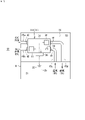
- FIG. 1 is a schematic configuration diagram of a ventilation system according to a first embodiment of the present disclosure
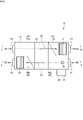
- FIG. It is a schematic cross-sectional explanatory drawing which looked at the ventilator from the top.
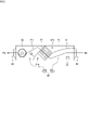
- FIG. 3 is a schematic cross-sectional explanatory view taken along line AA of FIG. 2;
- FIG. 3 is a schematic cross-sectional explanatory view taken along line BB of FIG. 2;
- It is a perspective view of a heat exchanger.
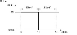
- FIG. 5 is an explanatory diagram showing operating states of the air supply fan in the first mode and the second mode (when stopped in the second mode);
- FIG. 4 is an explanatory diagram showing operating states of the air supply fan in the first mode and the second mode (in the case of intermittent operation in the second mode);
- FIG. 5 is an explanatory diagram showing operating states of the air supply fan in the first mode and the second mode (when stopped in the second mode);
- FIG. 4 is an explanatory diagram showing operating states of the air supply fan in the first mode and the
- FIG. 5 is an explanatory diagram showing operating states of the air supply fan in the first mode and the second mode (in the case of weak operation in the second mode);
- FIG. 4 is an explanatory diagram showing operating states of the exhaust fan in the first mode and the third mode (when stopped in the third mode);
- FIG. 10 is an explanatory diagram showing operating states of the exhaust fan in the first mode and the third mode (in the case of intermittent operation in the third mode);
- FIG. 5 is an explanatory diagram showing operating states of the exhaust fan in the first mode and the third mode (in the case of weak operation in the third mode);
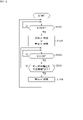
- FIG. 4 is an explanatory diagram showing a switching procedure of operation modes in the ventilation system according to the first embodiment;
- FIG. 7 is an explanatory diagram showing another example of a procedure for switching operation modes in the ventilation system according to the first embodiment
- FIG. 11 is an explanatory diagram showing a second example of the operation mode switching procedure in the ventilation system according to the first embodiment
- FIG. 11 is an explanatory diagram showing a third example of the operation mode switching procedure in the ventilation system according to the first embodiment
- FIG. 11 is an explanatory diagram showing a fourth example of the operation mode switching procedure in the ventilation system according to the first embodiment
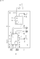
- FIG. 4 is a schematic configuration diagram of a ventilation system according to a second embodiment of the present disclosure
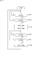
- FIG. 9 is an explanatory diagram showing a procedure for switching operation modes in the ventilation system according to the second embodiment
- FIG. 10 is an explanatory diagram showing another example of the operation mode switching procedure in the ventilation system according to the second embodiment
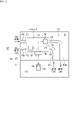
- FIG. 11 is a schematic configuration diagram of a ventilation system according to a third embodiment of the present disclosure
- FIG. 1 is a schematic configuration diagram of a ventilation system according to the first embodiment of the present disclosure.
- the ventilation system 10 shown in FIG. 1 is the first embodiment of the ventilation system of the present disclosure, and includes a ventilation device 11, a controller 36, and a first humidity sensor 38.
- the ventilation system 10 shown in FIG. the ventilator 11 that constitutes the ventilation system 10 is also referred to as a first ventilator 11A.
- first ventilator 11A the common configuration of the ventilator of each embodiment is described.
- the ventilation device 11 ventilates the indoor space S1.
- the indoor space S1 is an example of a target space to be ventilated by the ventilation system 10, and is a space inside the room R.
- the space outside the room R is called an outdoor space S2.
- the outdoor space S2 is outdoors.
- the outdoor space S2 may be any space that is outside the indoor space S1 and allows direct air flow to and from the outdoors, and may be, for example, a space inside a building.
- the ventilator 11 is installed in the space S3 behind the ceiling of the room R, and is connected to the indoor space S1 and the outdoor space S2 via ducts 45a to 45d.
- FIG. 2 is a schematic cross-sectional explanatory view of the ventilator viewed from above.
- FIG. 3 is a schematic cross-sectional explanatory view taken along line AA of FIG.
- FIG. 4 is a schematic cross-sectional explanatory view taken along line BB of FIG.
- the ventilator 11 has a casing 31 having a substantially rectangular parallelepiped box shape.
- a heat exchanger 32 , an exhaust fan 33 , and an air supply fan 34 are housed inside the casing 31 .
- the casing 31 is provided with a return air intake 41 , an exhaust air outlet 42 , an outside air intake 43 , and a supply air outlet 44 .
- a controller 36 is provided outside the casing 31 .
- the controller 36 is housed within a control box 37 provided outside the casing 31 .
- the controller 36 (hereinafter also referred to as “ventilation controller”) is a device that controls the operation of the ventilation device 11 , and controls the operation of the fan provided in the ventilation device 11 .
- the ventilation controller 36 is configured by, for example, a microcomputer having a processor such as a CPU, and memories such as RAM and ROM.
- the ventilation controller 36 may be realized as hardware using LSI, ASIC, FPGA, or the like.
- the ventilation controller 36 performs a predetermined function when the processor executes a program installed in memory. Note that the ventilation controller 36 may be provided integrally with the ventilation device 11 as a part of the ventilation device 11, or may be provided separately as a separate device from the ventilation device 11. FIG.
- the ventilator 11 further comprises a remote controller 25.
- the remote controller 25 is used to operate the ventilation device 11 to start/stop operation, and to set the indoor humidity, the intensity of air blowing, and the like.
- the remote controller 25 is communicably connected to the ventilation controller 36 by wire or wirelessly. A user can remotely operate the ventilator 11 by using the remote controller 25 .
- the remote controller 25 has a notification section 28 .
- the notification unit 28 is a part that, when an abnormality occurs in the ventilation device 11, notifies the occurrence of the abnormality by emitting a sound (voice, buzzer sound, etc.) or performing a display (lighting or blinking of a lamp, etc.). is.
- the remote controller 25 has the notification unit 28, but the notification unit 28 may be provided separately from the remote controller 25. may be provided in the remote controller 26 (see FIG. 13).
- the return air intake 41 is used to take air (return air) RA from the indoor space S1 into the casing 31.
- the exhaust outlet 42 is used to discharge the return air RA taken into the casing 31 to the outdoor space S2 as the exhaust EA.
- the outside air intake port 43 is used to take in the air (outside air) OA from the outdoor space S2 into the casing 31 .
- the supply air outlet 44 is used to supply the outside air OA taken into the casing 31 to the indoor space S1 as supply air SA.
- the return air intake 41 is connected to the indoor space S1 via a duct 45c.
- the exhaust air outlet 42 is connected to the outdoor space S2 via a duct 45b.
- an air passage that connects the indoor space S1 and the outdoor space S2 via the casing 31 with these ducts 45b and 45c is also referred to as an exhaust passage (exhaust passage 46 described later).
- the outside air intake 43 is connected to the outdoor space S2 via a duct 45a.
- the supply air outlet 44 is connected to the indoor space S1 via a duct 45d.
- an air passage that connects the indoor space S1 and the outdoor space S2 via the casing 31 by these ducts 45a and 45d is also referred to as an air supply passage (an air supply passage 47 described later).
- the return air RA taken in from the return air intake port 41 passes through the heat exchanger 32 and is discharged from the exhaust outlet 42 to the outdoor space S2 as the exhaust EA.
- this air flow is also referred to as "first air flow F1”.
- Outside air OA taken in from the outside air intake port 43 passes through the heat exchanger 32 and is supplied as supply air SA from the supply air outlet 44 to the indoor space S1.
- this air flow is also referred to as "second air flow F2".
- FIG. 5 is a perspective view of a heat exchanger.
- the heat exchanger 32 in this embodiment is an orthogonal total heat exchanger configured such that the first air flow F1 and the second air flow F2 are substantially perpendicular to each other.
- the heat exchanger 32 has a partition plate 32a and a partition plate 32b.
- the partition plates 32a and the partition plates 32b are alternately laminated with an appropriate adhesive.
- the heat exchanger 32 is generally formed in a substantially quadrangular prism shape.
- the partition plate 32a has heat conductivity and moisture permeability and is formed in a flat plate shape.
- the partition plate 32b is formed in a corrugated plate shape in which substantially triangular cross sections are continuously formed.
- the partition plate 32b forms an air passage between two adjacent partition plates 32a.
- the partition plates 32b are stacked with an angle changed by 90 degrees for each plate in the direction in which the partition plates 32a and the partition plates 32b are stacked (vertical direction in FIG. 5).
- an exhaust side passage 32c for passing the first air flow F1 and an air supply side passage 32d for passing the second air flow F2 are orthogonal to each other. formed by The air flowing through the exhaust side passage 32c and the air flowing through the air supply side passage 32d exchange sensible heat and latent heat (total heat exchange) via the partition plate 32a having heat conductivity and moisture permeability. ing.
- the inside of the casing 31 is divided by the heat exchanger 32 into two areas, an indoor space S1 side and an outdoor space S2 side.
- an upstream exhaust passage 46 a is formed in the casing 31 upstream of the heat exchanger 32 for the first air flow F 1
- the first A downstream exhaust passage 46b is formed downstream of the air flow F1.
- the upstream exhaust passage 46a and the downstream exhaust passage 46b constitute an exhaust passage 46 that communicates the indoor space S1 (see FIG. 1) and the outdoor space S2 (see FIG. 1) via the heat exchanger 32. .
- an upstream air supply passage 47a is formed upstream of the heat exchanger 32 for the second air flow F2 in the casing 31, and the second air supply passage 47a is formed upstream of the heat exchanger 32.
- a downstream air supply passage 47b is formed downstream of the air flow F2.
- the upstream air supply passage 47 a and the downstream air supply passage 47 b constitute an air supply passage 47 that communicates the indoor space S ⁇ b>1 and the outdoor space S ⁇ b>2 via the heat exchanger 32 .
- a partition wall 51 is provided between the upstream side exhaust passage 46a and the downstream side air supply passage 47b.
- a partition wall 52 is provided between the downstream side exhaust passage 46b and the upstream side air supply passage 47a.
- an exhaust fan 33 is arranged near the exhaust outlet 42 in the downstream exhaust passage 46b.
- the first airflow F1 is generated, and the return air RA from the indoor space S1 passes through the exhaust passage 46 and is discharged to the outdoor space S2 as the exhaust EA.
- an air supply fan 34 is arranged in the vicinity of the air supply outlet 44 in the downstream air supply passage 47b.
- a second airflow F2 is generated by operating the air supply fan 34, and the outside air OA of the outdoor space S2 passes through the air supply passage 47 and is supplied to the indoor space S1 as supply air SA.
- a first humidity sensor 38 is arranged in the vicinity of the return air intake 41 in the upstream exhaust passage 46a. This first humidity sensor 38 detects the humidity of the return air RA passing through the upstream side exhaust passage 46a. In other words, the first humidity sensor 38 detects the humidity of the air in the indoor space S1.
- the first humidity sensor 38 is provided in the upstream exhaust passage 46a inside the casing 31, but the installation position of the first humidity sensor 38 is not limited to this.
- the first humidity sensor 38 can be installed at a position where the humidity of the air in the indoor space S1 can be detected, for example, it may be installed inside the indoor space S1 or the duct 45c.
- the ventilation controller 36 controls the operation of the air supply fan 34 based on this first detected value K1.
- the notification unit 28 notifies when an abnormality occurs in the ventilation device 11 or when the humidity in the indoor space S1 detected by the first humidity sensor 38 exceeds a predetermined set value.
- a user of the ventilation system 10 can manually switch the operation mode of the ventilation device 11 using the remote controller 25 in response to the notification from the notification unit 28 .
- the ventilation system 10 has a "first mode" and a "second mode" as operation modes of the first ventilation device 11A.
- the first mode is a normal operation mode
- the second mode is a suitable operation mode when the humidity in the indoor space S1 is high.
- the first ventilator 11A is normally operated in the first mode, and when the humidity in the indoor space S1 is high, the operation mode is switched from the first mode to the second mode.
- the ventilation controller 36 controls the operation of the exhaust fan 33 and the supply air fan 34 to switch between the first mode and the second mode.
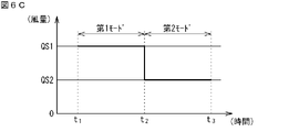
- 6A to 6C schematically show operating states of the air supply fan 34 in the first mode and the second mode.
- the first ventilator 11A is operated in the first mode from time t1 to time t2, switched from the first mode to the second mode at time t2, and operated from time t2 to time t3. indicates the case of driving in the second mode.
- the supply air fan 34 is operated with a normal supply air volume.
- the normal supply air volume at this time is called an average supply air volume QS1.
- the "normal supply air volume” here means at least one of the following. 1.
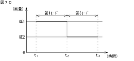
- 7A to 7C schematically show operating states of the exhaust fan 33 in the first mode and the second mode.
- the first ventilator 11A is operated in the first mode from time t1 to time t2, switched from the first mode to the second mode at time t2, and operated from time t2 to time t3. indicates the case of driving in the second mode.
- the exhaust fan 33 is operated with a normal exhaust air volume.
- the normal exhaust air volume at this time is called an average exhaust air volume QE1.
- the "normal exhaust air volume” referred to here means at least one of the following. 1. Exhaust air volume that can ensure a normal ventilation volume (ventilation frequency) desired by the user in the indoor space S1. 2. Exhaust air volume that can ensure the design ventilation volume (ventilation frequency) set for the indoor space S1. 3. The exhaust air volume obtained by operating the exhaust fan 33 and the supply air fan 34 at the target rotation speed set for the first mode.
- the return air RA with the average exhaust air volume QE1 is discharged from the indoor space S1 to the outdoor space S2, and the average air supply air volume is discharged from the outdoor space S2.
- the outside air OA of QS1 is supplied to the indoor space S1 to ventilate the indoor space S1. Furthermore, sensible heat and latent heat are exchanged between the return air RA from the indoor space S1 and the outside air OA from the outdoor space S2, and changes in temperature and humidity in the indoor space S1 can be suppressed.
- ventilation controller 36 modifies the operation of supply fan 34 from that in the first mode.
- the ventilation system 10 operates the air supply fan 34 in one of the modes shown in FIGS. 6A to 6C.
- the air supply fan 34 is stopped during operation of the first ventilator 11A in the second mode.
- the air volume (average supply air volume QS2) of the supply air SA (outside air OA) supplied from the outdoor space S2 to the indoor space S1 becomes "0".
- the air supply fan 34 operates intermittently while the first ventilator 11A is operating in the second mode. In other words, the air supply fan 34 alternately repeats a state of operating at the same average air supply air volume QS1 as in the first mode and a state of being stopped. In this case, the air volume (average air supply air volume QS2) of the supply air SA (outside air OA) supplied from the outdoor space S2 to the indoor space S1 is smaller than the average air supply air volume QS1 in the first mode.
- the air supply fan 34 is continuously operated at an air volume smaller than the average air supply air volume QS1 in the first mode.
- the air volume (average air supply air volume QS2) of the supply air SA (outside air OA) supplied from the outdoor space S2 to the indoor space S1 is smaller than the average air supply air volume QS1 in the first mode.
- the mode in which the fans 33 and 34 are continuously operated with a smaller amount of air than in the first mode is also referred to as "weak operation".
- the air supply fan 34 is weakly operated.
- the ventilation controller 36 controls the operation of the air supply fan 34 so that the average air supply air volume QS2 is smaller than the average air supply air volume QS1 in the first mode. ing. Note that the exhaust air volume of the exhaust fan 33 in each second mode may be the same as the exhaust air volume in the first mode unless it is changed to another mode.
- the outside air OA having a smaller air volume than in the first mode passes through the air supply passage 47 (see FIG. 4) and passes through the heat exchanger. 32 and supplied to the indoor space S1.
- the amount of outside air OA flowing into the heat exchanger 32 can be reduced compared to the first mode. Thereby, the moisture content of the heat exchanger 32 can be suppressed.
- the ventilation controller 36 changes the operation of the exhaust fan 33 from that in the first mode.
- the exhaust fan 33 in the third mode, is operated in one of the modes shown in FIGS. 7A to 7C.
- the exhaust fan 33 is stopped during operation of the first ventilation device 11A in the third mode.
- the air volume (average exhaust air volume QE2) of the exhaust EA (return air RA) discharged from the indoor space S1 to the outdoor space S2 becomes "0".
- the exhaust fan 33 operates intermittently while the first ventilator 11A is operating in the third mode.
- the exhaust fan 33 alternately repeats a state of operating at the same average exhaust air volume QE1 as in the first mode and a state of being stopped.
- the air volume (average exhaust air volume QE2) of the exhaust EA (return air RA) discharged from the indoor space S1 to the outdoor space S2 is smaller than the average exhaust air volume QE1 in the first mode.
- the exhaust fan 33 is weakly operated while the first ventilator 11A is operating in the third mode.
- the air volume (average exhaust air volume QE2) of the return air RA (exhaust EA) discharged from the indoor space S1 to the outdoor space S2 is smaller than the average exhaust air volume QE1 in the first mode.
- the ventilation controller 36 controls the operation of the exhaust fan 33 so that the average exhaust air volume QE2 is smaller than the average exhaust air volume QE1 in the first mode.
- the amount of air supplied by the air supply fan 34 in each third mode may be the same as the amount of air supplied in the first mode unless it is changed to another mode.
- the return air RA with an air volume smaller than that in the first mode flows through the exhaust passage 46 (see FIG. 3) into the heat exchanger 32, and flows into the outdoor space S2. exhausted.
- the amount of return air RA flowing into the heat exchanger 32 can be reduced compared to the first mode. Thereby, the moisture content of the heat exchanger 32 can be suppressed.
- the ventilation system 10 can simultaneously execute the second mode and the third mode.
- the operation mode of the air supply fan 34 can be selected from any of stop, intermittent operation, or weak operation.
- the mode of operation any one of stop, intermittent operation, or weak operation can be selected.
- the ventilation system 10 of the present disclosure executes only either the second mode or the third mode. It may be possible.
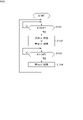
- the ventilation system 10 operates by switching between the first mode, the second mode, and the third mode according to the flowchart shown in FIG.
- the ventilation system 10 when the user turns on the first ventilator 11A using the remote controller 25, the first ventilator 11A operates in the first mode and the ventilation controller 36 controls the first ventilator 11A. Start.
- step (ST101) the ventilation controller 36 determines whether or not the first detected value K1 (relative humidity of the indoor space S1) of the first humidity sensor 38 is equal to or higher than the first predetermined value H1.
- the first predetermined value H1 is set to 80 (% RH).
- the value of the first predetermined value H1 is stored in the ventilation controller 36, and the user can use the remote controller 25 to change the value as appropriate.
- step (ST101) if the first detection value K1 of the first humidity sensor 38 is less than the first predetermined value H1 (NO), the ventilation controller 36 repeats step (ST101).
- step (ST101) if the first detection value K1 of the first humidity sensor 38 is greater than or equal to the first predetermined value H1 (YES), the ventilation controller 36 executes step (ST102).
- step (ST102) the ventilation controller 36 switches the operation mode of the first ventilator 11A from the first mode to the second mode or the third mode, and then executes step (ST103). At this time, the ventilation controller 36 performs notification by the notification unit 28 (see FIG. 1).
- the ventilation controller 36 determines whether or not the first detection value K1 of the first humidity sensor 38 is less than the third predetermined value H3.
- the third predetermined value H3 is less than or equal to the first predetermined value H1.
- the third predetermined value H3 can be set, for example, to 80 (% RH), which is the same as the first predetermined value H1, or 70 (% RH), which is lower than the first predetermined value.
- the value of the third predetermined value H3 is stored in the ventilation controller 36, and the user can use the remote controller 25 to change the value as appropriate.
- step (ST103) when the first detected value K1 of the first humidity sensor 38 is equal to or greater than the third predetermined value H3 (in the case of NO), the ventilation controller 36 operates the first ventilator in the second mode or the third mode. 11A is continued and step (ST103) is repeatedly executed.
- step (ST103) if the first detection value K1 of the first humidity sensor 38 is less than the third predetermined value H3 (YES), the ventilation controller 36 executes step (ST104).
- step (ST104) the ventilation controller 36 switches the operation mode of the first ventilator 11A from the second mode or the third mode to the first mode, and then executes step (ST101). At this time, the ventilation controller 36 stops the notification by the notification unit 28 (see FIG. 1). Whether to switch to the second mode or the third mode can be set in advance by the user and stored in the ventilation controller 36 .
- the ventilation controller 36 repeatedly executes the above steps (ST101) to (ST104) until the user turns “OFF” the first ventilation device 11A using the remote controller 25.
- the ventilation system 10 of this embodiment can switch the operation mode of the first ventilation device 11A from the first mode to the second mode or the third mode when the humidity in the indoor space S1 increases. Therefore, the inflow of high-humidity air from the indoor space S1 or the outdoor space S2 into the heat exchanger 32 is suppressed, the moisture content of the heat exchanger 32 is suppressed, and water leakage from the first ventilation device 11A is prevented. can be suppressed.
- the humidity in the indoor space S1 can be detected by providing the first humidity sensor 38 for detecting the humidity in the indoor space S1.
- the air volume of the exhaust fan 33 or the air supply fan 34 is reduced or set to "0". Therefore, it is possible to prevent the highly humid air from the indoor space S1 or the outdoor space S2 from passing through the heat exchanger 32 and prevent water leakage from the first ventilation device 11A.
- ventilation of the indoor space S1 may be suppressed.
- the ventilation system 10 detects the humidity of the indoor space S1 and controls the operation of the ventilation system 10 based on the detection result. is not suppressed, and the indoor space S1 can be sufficiently ventilated.
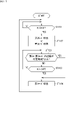
- the ventilation system 10 can be operated by switching between the first mode, the second mode, and the third mode according to the flowchart shown in FIG.
- a step (ST105) is provided instead of the step (ST102) in the flowchart shown in FIG.
- ST105 a step
- ST102 the step of the flowchart shown in FIG. 8
- each of the first to fourth modifications described below may be combined as appropriate.
- step (ST101) the ventilation controller 36 determines whether the first detection value K1 of the first humidity sensor 38 is equal to or greater than the first predetermined value H1.
- step (ST101) when the first detection value K1 of the first humidity sensor 38 is less than the first predetermined value H1 (K1 ⁇ H1) (NO), the ventilation controller 36 repeats step (ST101). do.
- step (ST101) when the first detection value K1 of the first humidity sensor 38 is equal to or greater than the first predetermined value H1 (K1 ⁇ H1) (if YES), the ventilation controller 36 executes step (ST105). .
- the ventilation controller 36 switches the operation mode of the first ventilator 11A from the first mode to the second mode and the third mode.
- the ventilation system 10 it is possible to switch from the first mode and simultaneously execute the second mode and the third mode.
- the amount of both the return air RA and the outside air OA flowing into the heat exchanger 32 can be reduced compared to the first mode. Thereby, the moisture content of the heat exchanger 32 can be further suppressed, and water leakage from the first ventilation device 11A can be suppressed.
- the ventilation system 10 can be operated by switching between the first mode, the second mode, and the third mode according to the flowchart shown in FIG.
- a step (ST111) is added as compared with the flowchart shown in FIG.
- ST111 the flowchart shown in FIG. 8
- step (ST101) the ventilation controller 36 determines whether the first detection value K1 of the first humidity sensor 38 is equal to or greater than the first predetermined value H1.
- step (ST101) when the first detection value K1 of the first humidity sensor 38 is less than the first predetermined value H1 (K1 ⁇ H1) (NO), the ventilation controller 36 repeats step (ST101). do.
- step (ST101) when the first detection value K1 of the first humidity sensor 38 is equal to or greater than the first predetermined value H1 (K1 ⁇ H1) (if YES), the ventilation controller 36 executes step (ST111). .
- step (ST111) the ventilation controller 36 determines whether or not the state in which the first detection value K1 is equal to or greater than the first predetermined value H1 (K1 ⁇ H1) continues for a predetermined time X or longer.
- the predetermined time X is set to 5 (minutes). The value of the predetermined time X is stored in the ventilation controller 36 and can be changed as appropriate using the remote controller 25 .
- step (ST111) if the state of (K1 ⁇ H1) is less than the predetermined time X (NO), the ventilation controller 36 returns to step (ST101) and continues the first mode.
- step (ST111) if the state of (K1 ⁇ H1) continues for the predetermined time X or longer (YES), the ventilation controller 36 executes step (ST102). In step (ST102), the ventilation controller 36 switches the operation mode of the first ventilator 11A from the first mode to the second mode or the third mode.
- the ventilation system 10 can be operated by switching between the first mode, the second mode, and the third mode according to the flowchart shown in FIG.
- a step (ST121) is added compared to the flowchart shown in FIG.
- the ventilation controller 36 executes step (ST102) and shifts to the second mode or the third mode, it determines whether or not the operation in the second mode or the third mode continues for a predetermined time Y or longer ( ST121).
- the predetermined time Y is set to 24 (hours).
- step (ST121) if the duration of operation in the second mode or third mode is less than the predetermined time Y (NO), the ventilation controller 36 executes step (ST103).
- step (ST121) if the duration of operation in the second mode or the third mode is equal to or longer than the predetermined time Y (if YES), the ventilation controller 36 executes step (ST104) to Switch the operation mode to the first mode.
- the operation mode of the first ventilator 11A can be switched to the first mode. As a result, it is possible to prevent the state in which the amount of ventilation in the indoor space S1 is decreasing from continuing for the predetermined time Y or more.
- the ventilation system 10 can be operated by switching between the first mode, the second mode, and the third mode according to the flowchart shown in FIG.
- a step (ST131) is added compared to the flowchart shown in FIG.
- ST131 the flowchart shown in FIG. 8
- step (ST103) if the first detected value K1 is smaller than the third predetermined value H3 (K1 ⁇ H3) (YES), the ventilation controller 36 executes step (ST131).
- step (ST131) the ventilation controller 36 determines whether or not the first detection value K1 is smaller than the third predetermined value H3 (K1 ⁇ H3) for a predetermined time Z or longer.
- the predetermined time Z is 5 (minutes).
- step (ST131) if the state where the first detected value K1 is smaller than the third predetermined value H3 (K1 ⁇ H3) continues for less than the predetermined time Z (in the case of NO), the ventilation controller 36 moves to step (ST103). to run.
- step (ST131) if the state where the first detected value K1 is smaller than the third predetermined value H3 (K1 ⁇ H3) continues for a predetermined time Z or longer (if YES), the ventilation controller 36 proceeds to step (ST104). Execute and switch the operation mode of the first ventilator 11A to the first mode.
- the operation mode of the first ventilation device 11A is switched to the first mode.
- the ventilation amount of the indoor space S1 can be quickly returned to the normal amount.
- FIG. 13 is a schematic configuration diagram of a ventilation system according to a second embodiment of the present disclosure.
- the ventilation system 15 shown in FIG. 13 is a second embodiment of the ventilation system of the present disclosure, and includes a first ventilation device 11A, a ventilation controller 36, a first humidity sensor 38, and a second humidity sensor 39. ing.
- the ventilation system 15 additionally includes a second humidity sensor 39 provided in the outdoor space S2.
- the second humidity sensor 39 detects the relative humidity of the air in the outdoor space S2.
- the detection signal (second detection value K2) is input to the ventilation controller 36.
- the ventilation controller 36 operates the exhaust fan 33 and the air supply fan 34 based on the first detection value K1 of the first humidity sensor 38 and the second detection value K2 of the second humidity sensor 39. to control.
- the first detection value K1 of the humidity of the first humidity sensor 38 is equal to or higher than the first predetermined value H1
- the second detection value K2 of the second humidity sensor 39 is the second predetermined value. If it is equal to or higher than the value H2, the operation mode of the first ventilator 11A is switched from the first mode to the second mode or the third mode.
- the second predetermined value H2 is set to 80 (% RH). Although the first predetermined value H1 and the second predetermined value H2 are set to the same value in this embodiment, they may be set to different values.
- the moisture temporarily generated in the indoor space S1 may There is a high possibility that the space S1 is highly humid. Under such conditions, even if the ventilator 11 is operated in the first mode, it is unlikely that the moisture content of the heat exchanger 32 will exceed the allowable amount. Therefore, in the ventilation system 15, the first detection value K1 of the humidity of the first humidity sensor 38 is equal to or higher than the first predetermined value H1, and the second detection value K2 of the second humidity sensor 39 is the second predetermined value H2. In the case above, the operation mode of the first ventilator 11A is switched to the second mode or the third mode.
- a high humidity e.g. 80 (% RH) or more
- the ventilation system 15 does not switch from the first mode to the second mode or the third mode when only the humidity in the indoor space S1 temporarily rises due to moisture or the like generated in the indoor space S1. I'm trying As a result, in the ventilation system 15, when there is no need to switch from the first mode to the second mode or the third mode, switching from the first mode to the second mode or the third mode is suppressed, and the operation of the ventilation device 11 is suppressed. Unnecessary mode switching can be suppressed.
- the ventilation system 15 operates by switching between the first mode, the second mode, and the third mode according to the flowchart shown in FIG.
- the ventilation system 15 when the user turns on the first ventilator 11A using the remote controller 25, the first ventilator 11A operates in the first mode and the ventilation controller 36 controls the first ventilator 11A. Start.
- step (ST201) the ventilation controller 36 determines whether or not the first detected value K1 is equal to or greater than the first predetermined value H1 (80% RH).
- step (ST201) if the first detection value K1 is less than the first predetermined value H1 (NO), the ventilation controller 36 repeats step (ST201).
- step (ST201) if the first detection value K1 is equal to or greater than the first predetermined value H1 (YES), the ventilation controller 36 executes step (ST202).
- step (ST202) when the second detection value K2 (relative humidity of the outdoor space S2) of the second humidity sensor 39 is less than the second predetermined value H2 (80% RH) (NO), the ventilation controller 36 , the process returns to step (ST201).
- step (ST202) if the second detection value K2 is equal to or greater than the second predetermined value H2 (YES), the ventilation controller 36 executes step (ST203).
- step (ST203) the ventilation controller 36 switches the operation mode of the first ventilator 11A from the first mode to the second mode or the third mode, and then executes step (ST204).
- the operation mode of the first ventilator 11A is switched from the first mode to the second mode or the third mode in step (ST203), but the ventilation system 15, in step (ST203), The operation mode of the first ventilator 11A may be switched from the first mode to the second mode and the third mode.
- the ventilation controller 36 determines whether or not the first detection value K1 of the first humidity sensor 38 is less than the third predetermined value H3.
- step (ST204) if the first detection value K1 is equal to or greater than the third predetermined value H3 (NO), the ventilation controller 36 repeats step (ST204).
- step (ST204) if the first detection value K1 is less than the third predetermined value H3 (YES), the ventilation controller 36 executes step (ST205).
- the ventilation controller 36 determines whether or not the second detection value K2 of the second humidity sensor 39 is less than the fourth predetermined value H4.
- the fourth predetermined value H4 is a value equal to or less than the second predetermined value.
- the fourth predetermined value H4 can be set, for example, to 80 (% RH), which is the same as the second predetermined value H2, or 70 (% RH), which is lower than the second predetermined value.
- the fourth predetermined value H4 may be the same as the third predetermined value H3.
- the value of the fourth predetermined value H4 is stored in the ventilation controller 36, and the user can use the remote controller 25 to change the value as appropriate.
- step (ST205) if the second detection value K2 is equal to or greater than the fourth predetermined value H4 (NO), the ventilation controller 36 returns the process to step (ST204).
- step (ST205) if the second detection value K2 is less than the fourth predetermined value H4 (YES), the ventilation controller 36 executes step (ST206).
- step (ST206) the ventilation controller 36 switches the operation mode of the first ventilator 11A from the second mode or the third mode to the first mode, and returns the process to step (ST201).
- the ventilation controller 36 repeatedly executes the above steps (ST201) to (ST206) until the user turns “OFF” the first ventilation device 11A using the remote controller 25.
- the ventilation system 15 can be operated by switching between the first mode, the second mode, and the third mode according to the flowchart shown in FIG.
- steps (ST211), (ST212), and (ST213) are added compared to the flowchart shown in FIG.
- steps (ST211), (ST212), and (ST213) are added compared to the flowchart shown in FIG.
- only parts related to steps different from the flowchart shown in FIG. 14 will be described.
- step (ST211) the ventilation controller 36 determines that the first detection value K1 is greater than or equal to the first predetermined value H1 (K1 ⁇ H1) and the second detection value K2 is greater than or equal to the second predetermined value H2 (K2 ⁇ H2). It is determined whether or not the state has continued for a predetermined time X or longer.
- step (ST211) if the state of (K1 ⁇ H1 and K2 ⁇ H2) continues for less than the predetermined time X (in the case of NO), the ventilation controller 36 returns to step (ST201) and returns to the first Continue mode.
- step (ST211) if the state of (K1 ⁇ H1, K2 ⁇ H2) continues for the predetermined time X or longer (YES), the ventilation controller 36 executes step (ST203).
- step (ST203) the ventilation controller 36 switches the operation mode of the first ventilator 11A from the first mode to the second mode or the third mode.
- the ventilation controller 36 determines whether or not the second mode or the third mode has continued for a predetermined time Y or longer.
- step (ST212) if the second mode or third mode continues for less than the predetermined time Y (NO), the ventilation controller 36 executes step (ST204).
- step (ST212) if the second mode or third mode continues for the predetermined time Y or longer (if YES), the ventilation controller 36 executes step (ST206) to change the operation mode of the first ventilator 11A. Switch to the first mode.
- step (ST213) the ventilation controller 36 determines that the first detection value K1 is less than the third predetermined value H3 (K1 ⁇ H3) and the second detection value K2 is less than the fourth predetermined value H4 (K2 ⁇ H4). It is determined whether or not the state has continued for a predetermined time Z or longer.
- step (ST213) the first detected value K1 is less than the third predetermined value H3 (K1 ⁇ H3) and the second detected value K2 is less than the fourth predetermined value H4 (K2 ⁇ H4). If it continues for less than time Z (NO), ventilation controller 36 executes step (ST212).
- step (ST213) the first detected value K1 is less than the third predetermined value H3 (K1 ⁇ H3) and the second detected value K2 is less than the fourth predetermined value H4 (K2 ⁇ H4). If it continues for time Z or longer (if YES), the ventilation controller 36 executes step (ST206) and switches the operation mode of the first ventilator 11A to the first mode.
- FIG. 16 is a schematic configuration diagram of a ventilation system according to a third embodiment of the present disclosure.
- the ventilation system 16 shown in FIG. 16 is a third embodiment of the ventilation system of the present disclosure, and includes a ventilation device 11, a ventilation controller 36, a first humidity sensor 38, a second humidity sensor 39, and an air conditioner. 12.
- the ventilation system 16 further includes the air conditioner 12 compared to the ventilation system 15 (see FIG. 13).
- the ventilator 11 constituting the ventilation system 16 is also referred to as a second ventilator 11B.
- the second ventilator 11B does not have the first humidity sensor 38 inside the casing 31 .
- the air conditioner 12 includes an outdoor unit 21 and an indoor unit 22.
- the indoor unit 22 and the second ventilation device 11B are installed in the space S3 behind the ceiling of the indoor space S1.
- the indoor unit 22 and the second ventilation device 11B may be installed on the wall of the indoor space S1, on the floor, under the ceiling, or the like.
- the indoor unit 22 and the second ventilation device 11B are not limited to being installed at the same location in the indoor space S1, but may be installed at separate locations.
- the air conditioner 12 adjusts the temperature of the air in the indoor space (air-conditioned space) S1 by performing a vapor compression refrigeration cycle using a refrigerant circuit including a compressor, a heat exchanger, an expansion valve, and the like.
- the outdoor unit 21 and the indoor unit 22 are connected by a refrigerant pipe 23 forming a refrigerant circuit.
- the indoor unit 22 takes in the air in the indoor space S1, performs heat exchange between the air and the refrigerant, and blows out the temperature-controlled conditioned air into the indoor space S1 again, thereby adjusting the temperature of the indoor space S1 to the desired value. adjust.
- the indoor unit 22 includes a controller 24 and a remote controller 26.
- a controller 24 (hereinafter also referred to as an “air-conditioning controller”) controls the operation of a fan, an electric valve, etc. housed in the indoor unit 22 .
- the air-conditioning controller 24 is configured by, for example, a microcomputer having a processor such as a CPU and memories such as RAM and ROM.
- the air conditioning controller 24 may be implemented as hardware using LSI, ASIC, FPGA, or the like.
- the air-conditioning controller 24 performs predetermined functions when the processor executes programs installed in the memory.
- the air conditioning controller 24 is also communicatively connected to the ventilation controller 36 of the second ventilation device 11B. Note that the air conditioning controller 24 may be provided in the outdoor unit 21 or may be provided in both the outdoor unit 21 and the indoor unit 22 .
- the remote controller 26 is used to start/stop the operation of the air conditioner 12, and to set the indoor temperature, the strength of the blowing air, and the like.
- the remote controller 26 is communicably connected to the air conditioning controller 24 of the indoor unit 22 by wire or wirelessly.
- a user can remotely operate the air conditioner 12 by using the remote controller 26 .
- the remote controller 25 for the second ventilator 11B is provided with the notification unit 28, but the remote controller 26 for the air conditioner 12 may be provided with the notification unit 28.
- the remote controller 26 of the indoor space S1 is provided with the first humidity sensor 38
- the outdoor unit 21 is provided with the second humidity sensor 39.
- the first humidity sensor 38 and the second humidity sensor 39 of the air conditioner 12 are shared with the second ventilation device 11B.
- Detected values K1 and K2 detected by the first humidity sensor 38 and the second humidity sensor 39 are input to the ventilation controller 36 via the air conditioning controller 24 .
- the ventilation controller 36 selects the operation mode (first mode, second mode, and third mode).
- the operation mode of the second ventilator 11B can be switched by the ventilation controller 36 according to the procedures shown in FIGS. 14 and 15. FIG.
- the first humidity sensor 38 and the second humidity sensor 39 can be easily provided in the ventilation system 16 .
- the manufacturing cost of the ventilation system 16 can be suppressed.
- Each of the ventilation systems 10, 15, and 16 in the above-described first to third embodiments includes a ventilator 11 that ventilates the indoor space S1, a first humidity sensor 38 that detects the humidity of the indoor space S1, and a ventilator. and a ventilation controller 36 that controls the operation of 11.
- the ventilation device 11 includes a heat exchanger 32, an air supply fan 34 that supplies the air outside the indoor space S1 to the indoor space S1 via the heat exchanger 32, and the air in the indoor space S1 through the heat exchanger 32. and an exhaust fan 33 that exhausts air to the outdoor space S2 via the exhaust fan 33.
- a first mode in which the ventilation controller 36 operates both the air supply fan 34 and the exhaust fan 33, a second mode in which the air supply fan 34 is stopped, intermittently operated, or weakly operated, or the exhaust fan 33 is stopped, Intermittent operation or a third mode of weak operation can be executed.
- the ventilation controller 36 switches from the first mode to Switch to the second mode or the third mode.
- the humidity in the indoor space S1 can be detected by providing the first humidity sensor 38 for detecting the humidity in the indoor space S1.
- the average air volume of the air supply fan 34 or the exhaust fan 33 is By lowering it, it is possible to suppress the passage of the highly humid air from the indoor space S1 or the outdoor space S2 through the heat exchanger 32 and to suppress water leakage from the ventilator 11 .
- the ventilation controller 36 switches from the first mode to the second mode. mode or the third mode. According to such a configuration, it is possible to suppress switching from the first mode to the second mode or the third mode when the humidity in the indoor space S1 temporarily increases. Thereby, unnecessary switching of the operation mode in the ventilator 11 can be suppressed.
- the ventilation controller 36 switches to the second mode or third mode to first mode. According to such a configuration, when the air in the indoor space S1 is no longer humid, unnecessary switching of the operation mode is suppressed, and by switching the operation mode of the ventilation device 11 to the first mode, the indoor space The ventilation volume of S1 can be returned to normal volume.
- Each ventilation system 15, 16 described above further includes a second humidity sensor 39 that detects the humidity of the outdoor space S2.
- the first detection value K1 is equal to or greater than the first predetermined value H1
- the second detection value K2 of the second humidity sensor 39 is the second predetermined value H2. If so, the ventilation controller 36 switches from the first mode to the second or third mode. According to such a configuration, by controlling the operation of the ventilation device 11 based on the humidity of both the indoor space S1 and the outdoor space S2, the inflow of air with high humidity into the heat exchanger 32 is more reliably suppressed. can do.
- Each of the ventilation systems 10, 15, and 16 in the above-described first to third embodiments includes a ventilator 11 that ventilates the indoor space S1, a first humidity sensor 38 that detects the humidity of the indoor space S1, and a ventilator. and a ventilation controller 36 that controls the operation of 11.
- the ventilation device 11 includes a heat exchanger 32, an air supply fan 34 that supplies the air outside the indoor space S1 to the indoor space S1 via the heat exchanger 32, and the air in the indoor space S1 through the heat exchanger 32. and an exhaust fan 33 that exhausts air to the outdoor space S2 via the exhaust fan 33.
- the ventilation controller 36 switches from the first mode to the second mode and Switch to the third mode.
- the ventilation systems 15 and 16 described above further include a second humidity sensor 39 that detects the humidity of the outdoor space S2.
- the ventilation controller 36 switches from the first mode to the second and third modes. According to such a configuration, by controlling the operation of the ventilation device 11 based on the humidity of both the indoor space S1 and the outdoor space S2, the inflow of air with high humidity into the heat exchanger 32 is more reliably suppressed. can do.
- the ventilation system 16 described above further includes the air conditioner 12 that generates conditioned air through heat exchange with the refrigerant and supplies the conditioned air to the indoor space S1.
- the air conditioner 12 includes an indoor unit 22 that supplies conditioned air to the indoor space S1, an outdoor unit 21 that is installed in the outdoor space S2, and a refrigerant pipe 23 that connects the indoor unit 22 and the outdoor unit 21.
- a second humidity sensor 39 are provided in the outdoor unit 21 . According to such a configuration, the second humidity sensor 39 can be easily provided in the ventilation system 16 including the air conditioner 12 . By sharing the second humidity sensor 39 with the air conditioner 12 and the ventilation device 11, the manufacturing cost of the ventilation system 16 can be suppressed.
- Each ventilation system 10, 15, 16 in the first to third embodiments described above further includes a notification unit 28 that notifies the ventilator 11 of an abnormality.
- the ventilation controller 36 notifies the ventilator 11 of abnormality through the notification unit 28 when the first detected value K1 is equal to or greater than the first predetermined value H1. According to such a configuration, it is possible to notify the administrator or user of each ventilation system 10, 15, 16 that the humidity in the indoor space S1 is high. It becomes possible to switch the operation mode of the ventilator 11 .
Landscapes
- Engineering & Computer Science (AREA)
- Chemical & Material Sciences (AREA)
- Combustion & Propulsion (AREA)
- Mechanical Engineering (AREA)
- General Engineering & Computer Science (AREA)
- Physics & Mathematics (AREA)
- Fluid Mechanics (AREA)
- Air Conditioning Control Device (AREA)
- Ventilation (AREA)
- Flow Control (AREA)
- Fluid-Driven Valves (AREA)
- Input Circuits Of Receivers And Coupling Of Receivers And Audio Equipment (AREA)
Abstract
Description
対象空間の換気を行う換気装置と、前記対象空間内の湿度を検出する第1検出部と、前記換気装置の運転を制御するコントローラと、を備え、
前記換気装置が、熱交換器と、前記対象空間外の空気を前記熱交換器を経由して前記対象空間内に給気する給気ファンと、前記対象空間内の空気を前記熱交換器を経由して前記対象空間外に排気する排気ファンと、を備え、
前記コントローラが、前記給気ファン及び前記排気ファンの双方を運転させる第1モード、及び、前記給気ファンを停止、間欠運転、又は平均給気風量を前記第1モードよりも低下させた状態で前記給気ファンを運転させる第2モード、又は、前記排気ファンを停止、間欠運転、若しくは平均排気風量を前記第1モードよりも低下させた状態で前記排気ファンを運転させる第3モード、を実行可能であり、
前記第1モードの実行中、前記第1検出部の第1検出値が第1所定値以上になった場合に、前記コントローラが、前記第1モードから前記第2モード又は前記第3モードに切り替える。
この構成によれば、対象空間内の湿度だけが一時的に上昇したような場合に、第1モードから第2モード又は第3モードに切り替わるのを抑制することができる。これにより、換気装置における運転モードの不要な切り替えを抑制することができる。
前記コントローラが、前記第2モード又は前記第3モードから前記第1モードに切り替える。
この構成によれば、対象空間内の空気が高湿でなくなった場合に、運転モードの不要な切り替えを抑制しつつ、換気装置の運転モードを第1モードに切り替えることで、対象空間内の換気量を通常の量へ戻すことができる。
前記第1モードの実行中、前記第1検出値が前記第1所定値以上であり、かつ、前記第2検出部の第2検出値が第2所定値以上である場合に、前記コントローラが、前記第1モードから前記第2モード又は第3モードに切り替える。
この構成によれば、対象空間内と対象空間外の両方の湿度に基づき換気装置の運転を制御することで、湿度の高い空気が熱交換器に流入するのをより確実に抑制することができる。
対象空間の換気を行う換気装置と、前記対象空間内の湿度を検出する第1検出部と、前記換気装置の運転を制御するコントローラと、を備え、
前記換気装置が、熱交換器と、前記対象空間外の空気を前記熱交換器を経由して前記対象空間内に給気する給気ファンと、前記対象空間内の空気を前記熱交換器を経由して前記対象空間外に排気する排気ファンと、を備え、
前記コントローラが、前記給気ファン及び前記排気ファンの双方を運転させる第1モード、前記給気ファンを停止、間欠運転、又は平均給気風量を前記第1モードよりも低下させた状態で前記給気ファンを運転させる第2モード、及び、前記排気ファンを停止、間欠運転、若しくは平均排気風量を前記第1モードよりも低下させた状態で前記排気ファンを運転させる第3モード、を実行可能であり、
前記第1モードの実行中、前記第1検出部の第1検出値が第1所定値以上になった場合に、前記コントローラが、前記第1モードから前記第2モード及び前記第3モードに切り替える。
前記第1モードの実行中、前記第1検出値が前記第1所定値以上であり、かつ、前記第2検出部の第2検出値が第2所定値以上である場合に、前記コントローラが、前記第1モードから前記第2モード及び前記第3モードに切り替える。
この構成によれば、対象空間内と対象空間外の両方の湿度に基づき換気装置の運転を制御することで、湿度の高い空気が熱交換器に流入するのをより確実に抑制することができる。
前記空気調和機が、前記対象空間内に調和空気を供給する室内機と、前記対象空間外に設置される室外機と、前記室内機と前記室外機との間をつなぐ冷媒配管とを含み、前記第2検出部が、前記室外機に設けられている。
この構成によれば、空気調和機を備えた換気システムにおいて、第2検出部を簡易に設けることができる。空気調和機及び換気システムで第2検出部を共用することで、換気システムの製造コストを抑制することができる。
前記第1検出値が前記第1所定値以上である場合に、前記コントローラが、前記報知部により前記換気装置の異常を報知する。
この構成によれば、対象空間内の湿度が高くなっていることを、換気システムの管理者やユーザに対して報知することができ、管理者等による手動操作で換気装置の運転モードを切り替えることが可能になる。これにより、熱交換器を備えた換気システムを対象空間内の湿度が高い条件下で使用した場合において、熱交換器の水分含有量をより確実に抑制することができる。
[第1実施形態]
図1は、本開示の第1の実施形態に係る換気システムの概略的な構成図である。図1に示す換気システム10は、本開示の換気システムの第1の実施形態であり、換気装置11と、コントローラ36と、第1湿度センサ38とを備えている。以下の説明では、換気システム10を構成する換気装置11を、第1換気装置11Aともいう。以下の説明で単に「換気装置11」という場合には、各実施形態の換気装置に共通の構成を説明している。
換気装置11は、室内空間S1の換気を行う。室内空間S1は、換気システム10により換気を行う対象空間の一例であり、部屋Rの内部の空間である。部屋Rの外部の空間を室外空間S2という。本実施形態では、室外空間S2を屋外としている。室外空間S2は、室内空間S1の外部であって屋外との間で直接空気の行き来が可能な空間であればよく、例えば建屋内の空間であってもよい。換気装置11は、部屋Rの天井裏のスペースS3に設置されており、ダクト45a~45dを介して室内空間S1及び室外空間S2と接続されている。
コントローラ36(以下、「換気コントローラ」ともいう)は、換気装置11の動作を制御する装置であり、換気装置11に備えられたファンの動作を制御する。換気コントローラ36は、例えば、CPU等のプロセッサ、RAM、ROM等のメモリを備えたマイクロコンピュータにより構成される。換気コントローラ36は、LSI、ASIC、FPGA等を用いてハードウェアとして実現されるものであってもよい。換気コントローラ36は、メモリにインストールされたプログラムをプロセッサが実行することによって、所定の機能を発揮する。なお、換気コントローラ36は、換気装置11の一部として当該換気装置11と一体で設けてもよいし、換気装置11とは別の装置として別体で設けてもよい。
図1に示すように、換気装置11は、さらにリモートコントローラ25を備えている。リモートコントローラ25は、換気装置11の運転開始/運転停止の操作や、室内の湿度、送風の強弱等の動作設定を行うために用いられる。リモートコントローラ25は、換気コントローラ36に有線又は無線で通信可能に接続されている。ユーザは、リモートコントローラ25を使用することによって、遠隔で換気装置11を操作することができる。
図1~図4に示すように、還気取入口41は、室内空間S1からの空気(還気)RAをケーシング31内に取り入れるために用いられる。排気吹出口42は、ケーシング31内に取り入れられた還気RAを、排気EAとして室外空間S2に排出するために用いられる。外気取入口43は、室外空間S2からの空気(外気)OAをケーシング31内に取り入れるために用いられる。給気吹出口44は、ケーシング31内に取り入れられた外気OAを、給気SAとして室内空間S1に供給するために用いられる。
図5は、熱交換器の斜視図である。本実施形態における熱交換器32は、第1の空気流F1と、第2の空気流F2とがほぼ直交するように構成された直交型の全熱交換器である。この熱交換器32は、仕切板32aと、隔壁板32bとを有している。仕切板32aと隔壁板32bとは適宜の接着剤により交互に積層されている。熱交換器32は、全体としてほぼ四角柱形状に形成されている。
図2及び図3に示すように、上流側排気通路46aにおいて、還気取入口41の近傍には第1湿度センサ38が配置されている。この第1湿度センサ38は、上流側排気通路46aを通る還気RAの湿度を検出する。言い換えると、第1湿度センサ38は、室内空間S1の空気の湿度を検出する。なお、本実施形態では、第1湿度センサ38を、ケーシング31内の上流側排気通路46aに設けているが、第1湿度センサ38の設置位置はこれに限定されない。第1湿度センサ38は、室内空間S1の空気の湿度を検出可能な位置に設置することができ、例えば、室内空間S1やダクト45cの内部に設置してもよい。
換気システム10は、第1換気装置11Aの運転モードとして「第1モード」と「第2モード」とを備えている。第1モードは、通常時の運転モードであり、第2モードは、室内空間S1の湿度が高い場合に適した運転モードである。換気システム10では、通常時は第1換気装置11Aを第1モードで運転し、室内空間S1の湿度が高い場合に、運転モードを第1モードから第2モードに切り替えて運転する。換気システム10では、換気コントローラ36が、排気ファン33及び給気ファン34の動作を制御することによって、第1モードと第2モードとを切り替えて実行する。
図6A~図6Cには、第1モード及び第2モードにおける給気ファン34の運転状態を模式的に示している。図6A~図6Cでは、第1換気装置11Aを、時刻t1から時刻t2の間は第1モードで運転し、時刻t2に第1モードから第2モードに切り替えて、時刻t2から時刻t3の間は第2モードで運転した場合を示している。
1.室内空間S1においてユーザが所望する通常の換気量(換気回数)を確保することができる給気風量。
2.室内空間S1に対して設定された設計上の換気量(換気回数)を確保することができる給気風量。
3.第1モードについて設定された目標回転数で排気ファン33及び給気ファン34を運転して得られる給気風量。
1.室内空間S1においてユーザが所望する通常の換気量(換気回数)を確保することができる排気風量。
2.室内空間S1に対して設定された設計上の換気量(換気回数)を確保することができる排気風量。
3.第1モードについて設定された目標回転数で排気ファン33及び給気ファン34を運転して得られる排気風量。
第2モードでは、換気コントローラ36によって、給気ファン34の動作を第1モードにおける動作から変更する。
第3モードでは、換気コントローラ36によって、排気ファン33の動作を第1モードにおける動作から変更する。
換気システム10は、図8に示すフロー図に従って、第1モードと、第2モード又は第3モードとを切り替えて運転する。換気システム10では、リモートコントローラ25によって、ユーザが第1換気装置11Aを「ON」にすると、第1換気装置11Aが第1モードで運転すると共に、換気コントローラ36による第1換気装置11Aの制御が開始する。
換気システム10は、図9に示すフロー図に従って、第1モードと第2モード及び第3モードを切り替えて運転することができる。図9に示すフロー図では、図8に示すフロー図のステップ(ST102)に代えて、ステップ(ST105)を設けている。以下の説明では、図8に示すフロー図と異なるステップに関連する部分のみを説明する。なお、換気システム10では、以下で説明する第1から第4の各変形例を適宜組み合わせてもよい。
換気システム10は、図10に示すフロー図に従って、第1モードと第2モード又は第3モードとを切り替えて運転することができる。図10に示すフロー図では、図8に示すフロー図に比べてステップ(ST111)がさらに加えられている。以下の説明では、図8に示すフロー図と異なるステップに関連する部分のみを説明する。
換気システム10は、図11に示すフロー図に従って、第1モードと第2モード又は第3モードとを切り替えて運転することができる。図11に示すフロー図では、図8に示すフロー図に比べてステップ(ST121)が加えられている。以下の説明では、図8に示すフロー図と異なるステップに関連する部分のみを説明する。
換気システム10は、図12に示すフロー図に従って、第1モードと第2モード又は第3モードとを切り替えて運転することができる。図12に示すフロー図では、図8に示すフロー図に比べてステップ(ST131)が加えられている。以下の説明では、図8に示すフロー図と異なるステップに関連する部分のみを説明する。
図13は、本開示の第2の実施形態に係る換気システムの概略的な構成図である。図13に示す換気システム15は、本開示の換気システムの第2の実施形態であり、第1換気装置11Aと、換気コントローラ36と、第1湿度センサ38と、第2湿度センサ39とを備えている。言い換えると、換気システム15は、換気システム10に比べて、室外空間S2に設けられた第2湿度センサ39が追加されている。図13に示す換気システム15では、図1から図12で説明した換気システム10と同じ構成については同じ符号が付されており、その説明を省略する。
図13に示すように、第2湿度センサ39は、室外空間S2の空気の相対湿度を検出する。第2湿度センサ39が室外空間S2の湿度を検出すると、その検出信号(第2検出値K2)は換気コントローラ36に入力される。換気システム15では、換気コントローラ36が、前述した第1湿度センサ38の第1検出値K1と第2湿度センサ39の第2検出値K2とに基づいて、排気ファン33及び給気ファン34の動作を制御する。
換気システム15は、図14に示すフロー図に従って、第1モードと第2モード又は第3モードとを切り替えて運転する。換気システム15では、リモートコントローラ25によって、ユーザが第1換気装置11Aを「ON」にすると、第1換気装置11Aが第1モードで運転すると共に、換気コントローラ36による第1換気装置11Aの制御が開始する。
換気システム15は、図15に示すフロー図に従って、第1モードと第2モード又は第3モードとを切り替えて運転することができる。図15に示すフロー図では、図14に示すフロー図に比べてステップ(ST211)、ステップ(ST212)、及びステップ(ST213)が加えられている。以下の説明では、図14に示すフロー図と異なるステップに関連する部分のみを説明する。
図16は、本開示の第3の実施形態に係る換気システムの概略的な構成図である。図16に示す換気システム16は、本開示の換気システムの第3の実施形態であり、換気装置11と、換気コントローラ36と、第1湿度センサ38と、第2湿度センサ39と、空気調和機12とを備えている。言い換えると、換気システム16は、換気システム15(図13参照)に比べて、空気調和機12がさらに追加されている。以下の説明では、換気システム16を構成する換気装置11を、第2換気装置11Bともいう。第2換気装置11Bは、ケーシング31内に第1湿度センサ38を有していない。なお、図16に示す換気システム16では、図1から図15で説明した各換気システム10、15と同じ構成については同じ符号が付されており、その説明を省略する。
空気調和機12は、圧縮機、熱交換器、膨張弁等を含む冷媒回路により蒸気圧縮式の冷凍サイクルを行うことによって、室内空間(空調対象空間)S1の空気の温度を調整する。室外機21と室内機22とは冷媒回路を構成する冷媒配管23で接続されている。室内機22は、室内空間S1の空気を取り込み、その空気と冷媒との間で熱交換を行い、温度調整された調和空気を再び室内空間S1に吹き出すことによって、室内空間S1の温度を所望に調整する。
上述した第1~第3の実施形態における各換気システム10、15、16は、室内空間S1の換気を行う換気装置11と、室内空間S1の湿度を検出する第1湿度センサ38と、換気装置11の運転を制御する換気コントローラ36と、を備えている。換気装置11が、熱交換器32と、室内空間S1外の空気を熱交換器32を経由して室内空間S1に給気する給気ファン34と、室内空間S1の空気を熱交換器32を経由して室外空間S2に排気する排気ファン33と、を備えている。換気コントローラ36が、給気ファン34及び排気ファン33の双方を運転させる第1モード、及び、給気ファン34を停止、間欠運転、又は弱運転させる第2モード、又は、排気ファン33を停止、間欠運転、又は弱運転させる第3モード、を実行可能である。各換気システム10、15、16は、第1モードの実行中、第1湿度センサ38の第1検出値K1が第1所定値H1以上になった場合に、換気コントローラ36が、第1モードから第2モード又は第3モードに切り替える。
このような構成によれば、室内空間S1の湿度が一時的に上昇したような場合に、第1モードから第2モード又は第3モードに切り替わるのを抑制することができる。これにより、換気装置11における運転モードの不要な切り替えを抑制することができる。
このような構成によれば、室内空間S1の空気が高湿でなくなった場合に、運転モードの不要な切り替えを抑制しつつ、換気装置11の運転モードを第1モードに切り替えることで、室内空間S1の換気量を通常の量へ戻すことができる。
このような構成によれば、室内空間S1と室外空間S2の両方の湿度に基づき換気装置11の運転を制御することで、湿度の高い空気が熱交換器32に流入するのをより確実に抑制することができる。
このような構成によれば、室内空間S1と室外空間S2の両方の湿度に基づき換気装置11の運転を制御することで、湿度の高い空気が熱交換器32に流入するのをより確実に抑制することができる。
このような構成によれば、空気調和機12を備えた換気システム16において、第2湿度センサ39を簡易に設けることができる。空気調和機12及び換気装置11で第2湿度センサ39を共用することで、換気システム16の製造コストを抑制することができる。
このような構成によれば、室内空間S1の湿度が高くなっていることを、各換気システム10、15、16の管理者やユーザに対して報知することができ、管理者等による手動操作で換気装置11の運転モードを切り替えることが可能になる。これにより、熱交換器32を備えた各換気システム10、15、16を室内空間S1の湿度が高い条件下で使用した場合において、熱交換器32の水分含有量が許容量を超えることによる換気装置11からの水漏れをより確実に抑制することができる。
11 :換気装置
11A :第1換気装置
11B :第2換気装置
12 :空気調和機
15 :換気システム(第2の実施形態)
16 :換気システム(第3の実施形態)
21 :室外機
22 :室内機
23 :冷媒配管
32 :熱交換器
33 :排気ファン
34 :給気ファン
36 :換気コントローラ(コントローラ)
38 :第1湿度センサ(第1検出部)
39 :第2湿度センサ(第2検出部)
46 :排気通路
47 :給気通路
S1 :室内空間(対象空間)
S2 :室外空間(対象空間の外部)
K1 :第1検出値
K2 :第2検出値
H1 :第1所定値
H2 :第2所定値
H3 :第3所定値
X :所定時間
Z :所定時間
Claims (8)
- 対象空間(S1)の換気を行う換気装置(11)と、前記対象空間内(S1)の湿度を検出する第1検出部(38)と、前記換気装置(11)の運転を制御するコントローラ(36)と、を備え、
前記換気装置(11)が、熱交換器(32)と、前記対象空間外(S2)の空気を前記熱交換器(32)を経由して前記対象空間内(S1)に給気する給気ファン(34)と、前記対象空間内(S1)の空気を前記熱交換器(32)を経由して前記対象空間外(S2)に排気する排気ファン(33)と、を備え、
前記コントローラ(36)が、前記給気ファン(34)及び前記排気ファン(33)の双方を運転させる第1モード、及び、前記給気ファン(34)を停止、間欠運転、又は平均給気風量(QS2)を前記第1モードよりも低下させた状態で前記給気ファン(34)を運転させる第2モード、又は、前記排気ファン(33)を停止、間欠運転、若しくは平均排気風量(QE2)を前記第1モードよりも低下させた状態で前記排気ファン(33)を運転させる第3モード、を実行可能であり、
前記第1モードの実行中、前記第1検出部(38)の第1検出値(K1)が第1所定値(H1)以上になった場合に、
前記コントローラ(36)が、前記第1モードから前記第2モード又は前記第3モードに切り替える、換気システム(10、15、16)。 - 前記第1モードの実行中、前記第1検出値(K1)が前記第1所定値(H1)以上である状態が所定時間(X)以上続いた場合に、
前記コントローラ(36)が、
前記第1モードから前記第2モード又は前記第3モードに切り替える、請求項1に記載の換気システム(10、15、16)。 - 前記第2モード又は前記第3モードの実行中、前記第1検出値(K1)が前記第1所定値(H1)以下の第3所定値(H3)未満である状態が所定時間(Z)以上継続された場合、
前記コントローラ(36)が、前記第2モード又は前記第3モードから前記第1モードに切り替える、請求項1又は請求項2に記載の換気システム(10)。 - 前記対象空間の外部(S2)の湿度を検出する第2検出部(39)をさらに備え、
前記第1モードの実行中、前記第1検出値(K1)が前記第1所定値(H1)以上であり、かつ、前記第2検出部(39)の第2検出値(K2)が第2所定値(H2)以上である場合に、
前記コントローラ(36)が、前記第1モードから前記第2モード又は前記第3モードに切り替える、請求項1から請求項3のいずれか1項に記載の換気システム(15、16)。 - 対象空間(S1)の換気を行う換気装置(11)と、前記対象空間内(S1)の湿度を検出する第1検出部(38)と、前記換気装置(11)の運転を制御するコントローラ(36)と、を備え、
前記換気装置(11)が、熱交換器(32)と、前記対象空間外(S2)の空気を前記熱交換器(32)を経由して前記対象空間内(S1)に給気する給気ファン(34)と、前記対象空間内(S1)の空気を前記熱交換器(32)を経由して前記対象空間外(S2)に排気する排気ファン(33)と、を備え、
前記コントローラ(36)が、前記給気ファン(34)及び前記排気ファン(33)の双方を運転させる第1モード、前記給気ファン(34)を停止、間欠運転、又は平均給気風量(QS2)を前記第1モードよりも低下させた状態で前記給気ファン(34)を運転させる第2モード、及び、前記排気ファン(33)を停止、間欠運転、若しくは平均排気風量(QE2)を前記第1モードよりも低下させた状態で前記排気ファン(33)を運転させる第3モード、を実行可能であり、
前記第1モードの実行中、前記第1検出部(38)の第1検出値(K1)が第1所定値(H1)以上になった場合に、
前記コントローラ(36)が、前記第1モードから前記第2モード及び前記第3モードに切り替える、換気システム(10、15、16)。 - 前記対象空間の外部(S2)の湿度を検出する第2検出部(39)をさらに備え、
前記第1モードの実行中、前記第1検出値(K1)が前記第1所定値(H1)以上であり、かつ、前記第2検出部(39)の第2検出値(K2)が第2所定値(H2)以上である場合に、
前記コントローラ(36)が、前記第1モードから前記第2モード及び前記第3モードに切り替える、請求項5に記載の換気システム(15、16)。 - 冷媒との熱交換により調和空気を生成し前記対象空間(S1)に供給する空気調和機(12)をさらに備え、
前記空気調和機(12)が、前記対象空間内(S1)に調和空気を供給する室内機(22)と、前記対象空間外(S2)に設置される室外機(21)と、前記室内機(22)と前記室外機(21)との間をつなぐ冷媒配管(23)とを含み、
前記第2検出部(39)が、前記室外機(21)に設けられている、請求項4又は請求項6に記載の換気システム(16)。 - 前記換気装置(11)の異常を報知する報知部(28)をさらに備え、
前記第1検出値(K1)が前記第1所定値(H1)以上である場合に、
前記コントローラ(36)が、
前記報知部(28)により前記換気装置(11)の異常を報知する、請求項1から請求項7のいずれか1項に記載の換気システム(10、15、16)。
Priority Applications (1)
| Application Number | Priority Date | Filing Date | Title |
|---|---|---|---|
| CN202280016972.2A CN116888408A (zh) | 2021-02-26 | 2022-02-21 | 换气系统 |
Applications Claiming Priority (2)
| Application Number | Priority Date | Filing Date | Title |
|---|---|---|---|
| JP2021-030429 | 2021-02-26 | ||
| JP2021030429A JP7284407B2 (ja) | 2021-02-26 | 2021-02-26 | 換気システム |
Publications (1)
| Publication Number | Publication Date |
|---|---|
| WO2022181524A1 true WO2022181524A1 (ja) | 2022-09-01 |
Family
ID=83048035
Family Applications (1)
| Application Number | Title | Priority Date | Filing Date |
|---|---|---|---|
| PCT/JP2022/006873 Ceased WO2022181524A1 (ja) | 2021-02-26 | 2022-02-21 | 換気システム |
Country Status (4)
| Country | Link |
|---|---|
| JP (1) | JP7284407B2 (ja) |
| CN (1) | CN116888408A (ja) |
| TW (1) | TWI810828B (ja) |
| WO (1) | WO2022181524A1 (ja) |
Citations (8)
| Publication number | Priority date | Publication date | Assignee | Title |
|---|---|---|---|---|
| JPH04283333A (ja) * | 1991-03-13 | 1992-10-08 | Daikin Ind Ltd | 熱交換換気装置 |
| JP2006234345A (ja) * | 2005-02-28 | 2006-09-07 | Fujitsu General Ltd | 換気装置および空気調和機 |
| JP2009293880A (ja) * | 2008-06-06 | 2009-12-17 | Mitsubishi Electric Corp | 熱交換換気装置 |
| JP2012172953A (ja) * | 2011-02-24 | 2012-09-10 | Mitsubishi Electric Corp | 熱交換換気装置 |
| JP2012172961A (ja) * | 2011-02-24 | 2012-09-10 | Mitsubishi Electric Corp | 熱交換換気装置 |
| JP2015143593A (ja) * | 2014-01-31 | 2015-08-06 | ダイキン工業株式会社 | 換気装置 |
| JP2016040503A (ja) * | 2014-08-12 | 2016-03-24 | 株式会社Lixil | 換気装置 |
| JP2020008251A (ja) * | 2018-07-11 | 2020-01-16 | ダイキン工業株式会社 | 換気装置 |
Family Cites Families (2)
| Publication number | Priority date | Publication date | Assignee | Title |
|---|---|---|---|---|
| WO2006035826A1 (ja) * | 2004-09-30 | 2006-04-06 | Max Co., Ltd | 換気装置、空調システム、換気システム及び建物 |
| JP5962029B2 (ja) * | 2012-01-27 | 2016-08-03 | 三菱電機株式会社 | 熱交換換気装置 |
-
2021
- 2021-02-26 JP JP2021030429A patent/JP7284407B2/ja active Active
-
2022
- 2022-02-21 CN CN202280016972.2A patent/CN116888408A/zh active Pending
- 2022-02-21 WO PCT/JP2022/006873 patent/WO2022181524A1/ja not_active Ceased
- 2022-02-25 TW TW111107027A patent/TWI810828B/zh active
Patent Citations (8)
| Publication number | Priority date | Publication date | Assignee | Title |
|---|---|---|---|---|
| JPH04283333A (ja) * | 1991-03-13 | 1992-10-08 | Daikin Ind Ltd | 熱交換換気装置 |
| JP2006234345A (ja) * | 2005-02-28 | 2006-09-07 | Fujitsu General Ltd | 換気装置および空気調和機 |
| JP2009293880A (ja) * | 2008-06-06 | 2009-12-17 | Mitsubishi Electric Corp | 熱交換換気装置 |
| JP2012172953A (ja) * | 2011-02-24 | 2012-09-10 | Mitsubishi Electric Corp | 熱交換換気装置 |
| JP2012172961A (ja) * | 2011-02-24 | 2012-09-10 | Mitsubishi Electric Corp | 熱交換換気装置 |
| JP2015143593A (ja) * | 2014-01-31 | 2015-08-06 | ダイキン工業株式会社 | 換気装置 |
| JP2016040503A (ja) * | 2014-08-12 | 2016-03-24 | 株式会社Lixil | 換気装置 |
| JP2020008251A (ja) * | 2018-07-11 | 2020-01-16 | ダイキン工業株式会社 | 換気装置 |
Also Published As
| Publication number | Publication date |
|---|---|
| CN116888408A (zh) | 2023-10-13 |
| TWI810828B (zh) | 2023-08-01 |
| JP2022131469A (ja) | 2022-09-07 |
| JP7284407B2 (ja) | 2023-05-31 |
| TW202242324A (zh) | 2022-11-01 |
Similar Documents
| Publication | Publication Date | Title |
|---|---|---|
| CN107923642B (zh) | 空调系统 | |
| JP7157722B2 (ja) | 空調換気システム | |
| US20100174414A1 (en) | Air-conditioning system | |
| EP3792565B1 (en) | Air conditioning system | |
| US12480680B2 (en) | Outside air treatment device and air conditioning system | |
| US12111067B2 (en) | Air conditioning system | |
| JPWO2019193639A1 (ja) | 空気調和システム | |
| JP2020008251A (ja) | 換気装置 | |
| US11384953B2 (en) | Air conditioning system | |
| WO2022071460A1 (ja) | 空調換気システム | |
| JP4478082B2 (ja) | 空気調和機の制御方法 | |
| US11698203B2 (en) | Air-conditioning system | |
| JP7284407B2 (ja) | 換気システム | |
| JPS6335321Y2 (ja) | ||
| JP7197811B2 (ja) | 換気システム | |
| JP7448827B2 (ja) | 空調システム | |
| JP7295454B1 (ja) | 換気システム | |
| JP2020008224A (ja) | 換気装置 | |
| JP2025150830A (ja) | 換気システム | |
| WO2023007666A1 (ja) | 空調換気システム | |
| JP2025059824A (ja) | 空調システム | |
| JP2024135872A (ja) | 換気空調システム | |
| JP2026017853A (ja) | 給排気制御システム | |
| JP2025149704A (ja) | 換気システム |
Legal Events
| Date | Code | Title | Description |
|---|---|---|---|
| 121 | Ep: the epo has been informed by wipo that ep was designated in this application |
Ref document number: 22759560 Country of ref document: EP Kind code of ref document: A1 |
|
| WWE | Wipo information: entry into national phase |
Ref document number: 202317055430 Country of ref document: IN |
|
| WWE | Wipo information: entry into national phase |
Ref document number: 202280016972.2 Country of ref document: CN |
|
| NENP | Non-entry into the national phase |
Ref country code: DE |
|
| 32PN | Ep: public notification in the ep bulletin as address of the adressee cannot be established |
Free format text: NOTING OF LOSS OF RIGHTS PURSUANT TO RULE 112(1) EPC (EPO FORM 1205A DATED 27/11/2023) |
|
| 122 | Ep: pct application non-entry in european phase |
Ref document number: 22759560 Country of ref document: EP Kind code of ref document: A1 |