WO2022176693A1 - Embrayage centrifuge et véhicule à selle - Google Patents
Embrayage centrifuge et véhicule à selle Download PDFInfo
- Publication number
- WO2022176693A1 WO2022176693A1 PCT/JP2022/004826 JP2022004826W WO2022176693A1 WO 2022176693 A1 WO2022176693 A1 WO 2022176693A1 JP 2022004826 W JP2022004826 W JP 2022004826W WO 2022176693 A1 WO2022176693 A1 WO 2022176693A1
- Authority
- WO
- WIPO (PCT)
- Prior art keywords
- pressure plate
- weight
- centrifugal clutch
- centrifugal
- force
- Prior art date
Links
- 230000005540 biological transmission Effects 0.000 claims abstract description 128
- 230000033001 locomotion Effects 0.000 claims abstract description 110
- 230000007246 mechanism Effects 0.000 claims abstract description 93
- 238000006073 displacement reaction Methods 0.000 claims description 32
- 230000001105 regulatory effect Effects 0.000 claims description 6
- 230000008602 contraction Effects 0.000 claims description 5
- 230000004044 response Effects 0.000 claims description 3
- 230000008859 change Effects 0.000 abstract description 20
- 230000007423 decrease Effects 0.000 abstract description 9
- 230000000694 effects Effects 0.000 abstract description 3
- 238000006243 chemical reaction Methods 0.000 description 4
- 238000010586 diagram Methods 0.000 description 4
- 230000009471 action Effects 0.000 description 2
- 230000008878 coupling Effects 0.000 description 2
- 238000010168 coupling process Methods 0.000 description 2
- 238000005859 coupling reaction Methods 0.000 description 2
- 238000000034 method Methods 0.000 description 2
- 230000027455 binding Effects 0.000 description 1
- 238000009739 binding Methods 0.000 description 1
- 238000002485 combustion reaction Methods 0.000 description 1
- 238000001514 detection method Methods 0.000 description 1
- 230000005611 electricity Effects 0.000 description 1
- 238000005516 engineering process Methods 0.000 description 1
- 239000000446 fuel Substances 0.000 description 1
- 230000012447 hatching Effects 0.000 description 1
- 239000000203 mixture Substances 0.000 description 1
- 230000007935 neutral effect Effects 0.000 description 1
- 230000000149 penetrating effect Effects 0.000 description 1
- 230000002093 peripheral effect Effects 0.000 description 1
Images


Classifications
-
- F—MECHANICAL ENGINEERING; LIGHTING; HEATING; WEAPONS; BLASTING
- F16—ENGINEERING ELEMENTS AND UNITS; GENERAL MEASURES FOR PRODUCING AND MAINTAINING EFFECTIVE FUNCTIONING OF MACHINES OR INSTALLATIONS; THERMAL INSULATION IN GENERAL
- F16D—COUPLINGS FOR TRANSMITTING ROTATION; CLUTCHES; BRAKES
- F16D13/00—Friction clutches
- F16D13/22—Friction clutches with axially-movable clutching members
- F16D13/38—Friction clutches with axially-movable clutching members with flat clutching surfaces, e.g. discs
- F16D13/52—Clutches with multiple lamellae ; Clutches in which three or more axially moveable members are fixed alternately to the shafts to be coupled and are pressed from one side towards an axially-located member
-
- F—MECHANICAL ENGINEERING; LIGHTING; HEATING; WEAPONS; BLASTING
- F16—ENGINEERING ELEMENTS AND UNITS; GENERAL MEASURES FOR PRODUCING AND MAINTAINING EFFECTIVE FUNCTIONING OF MACHINES OR INSTALLATIONS; THERMAL INSULATION IN GENERAL
- F16D—COUPLINGS FOR TRANSMITTING ROTATION; CLUTCHES; BRAKES
- F16D43/00—Automatic clutches
- F16D43/02—Automatic clutches actuated entirely mechanically
- F16D43/04—Automatic clutches actuated entirely mechanically controlled by angular speed
- F16D43/06—Automatic clutches actuated entirely mechanically controlled by angular speed with centrifugal masses actuating axially a movable pressure ring or the like
- F16D43/08—Automatic clutches actuated entirely mechanically controlled by angular speed with centrifugal masses actuating axially a movable pressure ring or the like the pressure ring actuating friction plates, cones or similar axially-movable friction surfaces
Definitions
- the present invention relates to an operable centrifugal clutch that transmits the rotational driving force of a power source to a transmission.
- Patent Document 1 shows a centrifugal clutch provided in a vehicle.
- the centrifugal clutch disclosed in Patent Document 1 transmits rotational driving force of an engine, which is a power source, to a transmission.
- the centrifugal clutch of Patent Document 1 has friction plates (drive plate and driven plate), weights, and an intermittent mechanism. Each friction plate is engaged by pressing. Rotational driving force of the engine is transmitted to the transmission mechanism by the engagement of each friction plate. The weights are moved by the centrifugal force associated with the rotation, so that the respective friction plates are engaged with each other. Rotation driving force is thereby transmitted.
- the disconnecting mechanism has, for example, a push rod. When the friction plates are separated from each other by the operation of the connecting/disconnecting mechanism, the transmission of the rotational driving force is cut off and the clutch is released.
- a mechanism operated by an operating force from a clutch lever can be considered.
- the clutch lever When the clutch lever is operated, the released state of power transmission changes to the connected state at a position in the middle of the displacement of the clutch lever.
- Each friction plate wears as the centrifugal clutch is used. If the thickness of each friction plate decreases due to wear, the engagement may not be completed even if each friction plate is in the engaged position before wear. Wear of the friction plates also affects the engagement of the friction plates when the weight moves due to centrifugal force. Further, the position where the weight moves on the centrifugal clutch and the connection position on the clutch lever are also related to each other.
- centrifugal clutch it is desired to suppress the influence of wear on the connection state of the friction plates, and also to suppress the change in the connection position due to the rotation speed.
- An object of the present invention is to provide a centrifugal clutch and a straddle-type vehicle that can suppress the influence of wear on the connection state of the friction plates and also suppress changes in the connection position due to rotational speed.
- the centrifugal clutch of Patent Document 1 has a screw for adjustment inside.
- the size of the clearance between the friction plates, which increases with wear, is adjusted by adjusting the screws.
- the centrifugal clutch of Patent Document 1 is required to adjust the screw inside the centrifugal clutch according to the degree of wear.
- the inventor focused on movement of the weight due to centrifugal force in relation to the adjustment of the gap. For example, the weight receives centrifugal force and moves outward as the rotational speed increases, thereby engaging each friction plate. Engagement of the friction plates is completed when the weight moves to the connected position.
- the inventor considered a configuration in which the weight at the connection position where the friction plate engages has a margin for further outward movement. In this configuration, the weight at the connection position moves outward from the connection position by receiving a larger centrifugal force. Even if each friction plate wears, the engagement of each friction plate is completed while the weight is moving outward from the connecting position. As a result, even if wear occurs, the engagement of each friction plate is completed by centrifugal force rather than screwing.
- the weight that moves outward from the connection position moves the second pressure plate in the release direction by the reaction force that presses the friction plate.
- the release direction is the direction opposite to the pressing direction.
- the inventor of the present invention came up with the idea of moving the operating force transmission member that transmits the operating force of the clutch lever relative to the second pressure plate when the second pressure plate moves in the releasing direction. Specifically, it is conceivable to provide a relative movement mechanism.
- the relative movement mechanism moves the operating force transmission member relative to the second pressure plate so as to reduce or eliminate a gap between the operating force transmission member and the second pressure plate.
- the centrifugal clutch itself can suppress changes in the connection position of the clutch lever due to wear, without adjusting screws or adding an adjusting mechanism using an actuator.
- the centrifugal clutch according to each aspect of the present invention completed based on the above knowledge has the following configuration.
- the centrifugal clutch for transmitting rotational driving force of a power source to a transmission
- the centrifugal clutch is a first friction plate (113) that rotates integrally with a first rotating member (111) that receives the rotational driving force of the power source; a second friction plate (114) that rotates integrally with the second rotating member; One of the first friction plates and the second friction plates is pressed against the other friction plate in a pressing direction parallel to the axis of rotation to engage the first friction plates and the second friction plates with each other.
- An operating force transmission member (121) displaced to A first pressure plate disposed between the second pressure plate and the first pressure plate in the direction of the rotation axis and moving radially outward of the rotation axis under centrifugal force of the rotation of the first rotating member.
- the centrifugal clutch is arranged at a position between the power source and the transmission in the rotational drive transmission path.
- a centrifugal clutch is connected with the output shaft of the power source.
- a centrifugal clutch is connected with the transmission.
- the centrifugal clutch may be connected to the output shaft via a driving force transmission component other than the output shaft of the power source.
- the centrifugal clutch may, for example, be connected to the transmission via a driving force transmission component other than the transmission.
- the transmission is, for example, a manual transmission that receives a driver's operation force and switches the gear ratio.
- the transmission is operated by the driver's foot.
- the transmission switches gear ratios by operating force received from the driver's feet.
- the second elastic body is an elastic body for urging the second pressure plate in the pressing direction.
- the range of movement of the second pressure plate in the pressing direction is regulated by the movement range regulating portion.
- the first elastic body urges the first pressure plate in the release direction. Therefore, the first pressure plate has not moved to the position where the first friction plate and the second friction plate engage with each other. That is, the first friction plate and the second friction plate are not engaged.
- the first rotating member receives the rotational driving force of the power source and rotates, the first weight rotates together with the first rotating member. The first weight moves outward along the first pressure plate drive under the centrifugal force of rotation. Outward is the direction away from the axis of rotation.
- a first pressure plate driving section is provided on one or both of the mutually facing surfaces of the second pressure plate and the first pressure plate.
- the first pressure plate driving portion is, for example, a slope portion.
- the first pressure plate driving portion is formed such that the distance between the second pressure plate and the first pressure plate becomes smaller toward the outer side in the radial direction.
- the first weight moves outward along the first pressure plate driving portion to move the first pressure plate in the pressing direction against the biasing force of the first elastic body.
- the first pressure plate presses one of the first friction plate and the second friction plate against the other friction plate in the pressing direction. This causes the first friction plate and the second friction plate to engage with each other.
- the first weight receives centrifugal force and moves first to the connecting position.
- connection position is the position at which the engagement of the first friction plate and the second friction plate is completed.
- the connection position is also the position where the first weight has room to move further outward.
- the first weight then moves outward from the connecting position by being subjected to a greater centrifugal force. Thereby, the first weight moves the second pressure plate in the release direction against the biasing force of the second elastic body.
- the connection state may become incomplete.
- the first weight has room to move further outward at the connection position. Therefore, when the first friction plate and the second friction plate wear, the first weight moves outward from the initial connection position. This allows the first friction plate and the second friction plate to complete engagement. Therefore, even if wear occurs, the connected state can be achieved by centrifugal force without adjustment of screws or the like.
- the operating force transmission member receives an operating force for releasing the centrifugal clutch and displaces the second pressure plate.
- the operating force transmission member receives the operating force and displaces the second pressure plate in the release direction against the pressing force of the second elastic body. This releases the centrifugal clutch. That is, the centrifugal clutch is released, for example, by operating the clutch lever.
- a connected state caused by centrifugal force and a released state caused by operating force are realized.
- the centrifugal clutch of (1) when the first weight moves outward from the connected position, the first weight moves the second pressure plate in the release direction against the biasing force of the second elastic body.
- the amount of operation from the non-operating position to the releasing position increases, for example, when the clutch lever is in the operating position. do.
- the amount of operation from the non-operating position to the released position of the clutch lever corresponds to play of the clutch lever. That is, play of the clutch lever differs between when the first weight is at the connected position and when it is outside the connected position. For example, even when an electric actuator outputs an operating force, there is an effect due to play.
- the relative movement mechanism reduces or eliminates the gap generated between the operating force transmission member and the second pressure plate when the first weight moves the second pressure plate in the release direction. , the operating force transmission member is moved relative to the second pressure plate.
- the relative movement mechanism moves the operating force transmission member relative to the second pressure plate without using the actuator.
- the centrifugal clutch can suppress changes in the operating position due to wear by itself without adjusting screws or adding an adjusting mechanism using an actuator.
- the centrifugal clutch of (1) The relative movement mechanism (130) is interposed between the second pressure plate (117) and the operating force transmission member (121), and comprises a second weight (131) and a first cam portion (132). have the second weight (131) rotates around the axis of rotation (Ax) and is moved outward by centrifugal force of rotation; By contacting the second weight (131), the first cam portion (131) moves from the operating force transmission member (121) by the outward movement of the second weight (131). extending the length in the direction of the rotation axis (Ax) of the relative movement mechanism (130) to the second pressure plate (117); centrifugal clutch.
- the relative movement mechanism is interposed between the second pressure plate and the operating force transmission member.
- the relative movement mechanism has a second weight and a first cam portion.
- the second weight rotates around the axis of rotation.
- the second weight moves outward due to the centrifugal force of rotation.
- the second pressure plate extends the length in the direction of the rotational axis of the relative movement mechanism from the operating force transmission member to the second pressure plate by movement of the second weight.
- the first cam portion in contact with the second weight causes the movement from the operating force transmission member to the second pressure plate.
- the length in the direction of the rotation axis of the relative movement mechanism between is extended. Therefore, the displacement of the second pressure plate in the direction of the rotation axis caused by the outward movement of the first weight subjected to the centrifugal force from the initial connection position will have an effect on the second weight subjected to the centrifugal force. and cams. Therefore, it is possible to suppress the change in the connection position between when the vehicle starts running and during the vehicle running by utilizing the centrifugal force acting on the two weights in common. Therefore, for example, a change in connection position between when the vehicle starts running and when the vehicle is running can be easily suppressed.
- the centrifugal clutch of (2) The relative movement mechanism (130) rotates together with the second pressure plate (117) and the second weight, and displaces relative to the second pressure plate (117) in the direction of the rotation axis (Ax). having a displaceable member (134), The first cam portion (132) is provided on at least one of the second pressure plate (171) and the displacement member (134), centrifugal clutch.
- the relative movement mechanism has the displacement member.
- the displacement member rotates together with the second pressure plate.
- the displacement member is relatively displaceable in the direction of the rotation axis with respect to the second pressure plate.
- the first cam portion is provided on at least one of the second pressure plate and the displacement member.
- the centrifugal clutch of (2) or (3) The rotation speed of the second weight (131) at which the centrifugal force applied to the second weight (131) and the biasing force of the third elastic body (133) that suppresses the movement of the second weight (131) are balanced is It is smaller than the rotation speed at which the centrifugal force applied to the second pressure plate (117) and the biasing force of the second elastic body (116) are balanced. centrifugal clutch.
- the centrifugal force received by the second weight and the biasing force of the third elastic body are balanced at a speed lower than the speed at which the centrifugal force received by the second pressure plate and the second elastic body are balanced. Therefore, when the speed increases, the rotation axis from the operating force transmission member to the second pressure plate does not lag behind the movement of the second pressure plate in the release direction due to the outward movement of the first weight. Directional length can be extended. Therefore, in any speed range, the change in the connection position of the clutch lever at the start of running and during running can be suppressed by utilizing the centrifugal force acting on the two weights in common. Therefore, in a wide range of speeds, it is easy to suppress the change in the connection position between when the vehicle starts running and when it is running.
- the centrifugal clutch of any one of (1) to (4) The relative movement mechanism (330) is Interposed between the second pressure plate (117) and the operating force transmission member (121), the second pressure plate (117) is pushed by the first pressure plate (115) in the release direction (R). It has a one-way slide mechanism (340) that is freely expandable when moving and restricts contraction when the operating force transmission member (121) receives the operating force and moves in the release direction (R), centrifugal clutch.
- the relative movement mechanism has a one-way slide mechanism interposed between the second pressure plate and the operating force transmission member.
- the one-way slide mechanism can freely extend when the second pressure plate is pushed by the first pressure plate and moves in the release direction. Therefore, when the speed increases, the rotation axis from the operating force transmission member to the second pressure plate does not lag behind the movement of the second pressure plate in the release direction due to the outward movement of the first weight. The length in any direction can be extended.
- contraction of the length from the operating force transmission member to the second pressure plate in the direction of the rotation axis is restricted. Therefore, the second pressure plate starts to move in accordance with the operation of the clutch lever while maintaining the extended length. Therefore, in a wide operating range, it is easy to suppress the change in the connecting position between when the vehicle starts running and when the vehicle is running.
- the centrifugal clutch of (2) The second weight (131) receives torque transmission from the second pressure plate (117) to accelerate and decelerate rotation, The second pressure plate (117) is formed to transmit deceleration torque to the second weight (131) and move the second weight (131) inward in the radial direction. having two cam parts (141), centrifugal clutch.
- the second weight of the relative movement mechanism moves outward due to the centrifugal force that the second weight receives. Due to the frictional force generated between the second weight and the first cam portion, the second weight that has moved outward may become difficult to return inward while maintaining the state of outward movement even if the centrifugal force is reduced. .
- the second pressure plate has the second cam portion. The second cam portion moves the second weight radially inward when the rotation of the second pressure plate slows down. Therefore, according to the configuration of (6), the second weight can easily return radially inward when the rotation is decelerated even if a frictional force is generated between the second weight and the first cam portion.
- the centrifugal force is reduced and the second weight tends to return to the original position. Therefore, the adjustment of the displacement in the direction of the rotation axis of the second pressure plate caused by the movement of the first weight outward from the connection position, which receives the centrifugal force, is easily restored when the centrifugal force is reduced. Therefore, it is possible to more precisely suppress the change in the connecting position between when the vehicle starts running and when it is running. Therefore, for example, a change in connection position between when the vehicle starts running and when the vehicle is running can be easily suppressed.
- a straddle-type vehicle The straddle-type vehicle power source; a transmission; and a centrifugal clutch according to any one of (1) to (6) for transmitting the rotational driving force of the power source to the transmission.
- a straddle-type vehicle refers to a vehicle in which a rider sits astride a saddle.
- a straddle-type vehicle is configured to run or turn by shifting the rider's weight.
- a straddle-type vehicle includes a handlebar that is gripped by a rider.
- a straddle-type vehicle is configured such that a rider performs posture control by shifting his or her weight while gripping a handlebar with both hands during running or turning.
- a straddle-type vehicle has drive wheels.
- Straddle-type vehicles are not particularly limited, and include, for example, motorcycles (motorcycles, tricycles, etc.) and ATVs (All-Terrain Vehicles).
- a straddle-type vehicle is, for example, a lean vehicle configured to lean in the direction of the turning center on the left and right when turning.
- the power source is, for example, an engine.
- An engine outputs power generated by combustion of a mixture of air and fuel as torque and rotation speed of a crankshaft, which is an output shaft.
- the power source is not particularly limited, and may be, for example, a motor operated by electric power, or may be a combination of an engine and a motor.
- the transmission has multiple gear ratios that can be switched.
- the number of gear ratios is not particularly limited, and, for example, there are 4 to 6 gear ratios in addition to the neutral position.
- the operating force transmission member is, for example, a push rod that is pushed by a rotating cam portion that rotates upon receiving the operating force of the clutch lever.
- the means for transmitting the operating force of the clutch lever to the operating force transmission member is not limited to the rotating cam portion, and may be, for example, a screw that converts rotation into linear motion, or a hydraulically operated piston.
- the operating force transmission member is not limited to a push rod that pushes the second pressure plate in the release direction.
- the operating force transmission member may be, for example, a pull rod that hooks the second pressure plate and pulls it in the release direction.
- a centrifugal clutch is, for example, a multi-plate clutch having a plurality of first friction plates and a plurality of second friction plates, which are alternately arranged in the rotation axis direction.
- the centrifugal clutch may be a single-plate clutch having one first friction plate and one second friction plate.
- the first pressure plate presses one of the first friction plate and the second friction plate against the other friction plate in a pressing direction parallel to the rotation axis
- the first pressure plate pushes the first friction plate to the first friction plate.
- the first pressure plate may press the second friction plate against the first friction plate.
- the first pressure plate in the multi-plate clutch may press the plurality of second friction plates and the plurality of first friction plates against each other.
- the second pressure plate is formed of, for example, one member.
- the second pressure plate may be composed of, for example, multiple members.
- the second pressure plate may be composed of, for example, a member that presses the friction plate and a member that contacts the movement range restricting portion.
- the first elastic body is composed of, for example, a spring.
- the first elastic body is composed of, for example, a coil spring.
- the first elastic body is not particularly limited, and may be composed of, for example, a disc spring or rubber.
- the first elastic body is not interposed between the first pressure plate and the first friction plate and the second friction plate. More specifically, the first elastic body is provided so as not to be mechanically connected in series between the first pressure plate and the first and second friction plates. More specifically, the first elastic body is provided such that the first elastic body, the first friction plate and the second friction plate are mechanically connected in parallel with the first pressure plate.
- the second elastic body is composed of, for example, a spring.
- the second elastic body is composed of, for example, a disc spring.
- the second elastic body is not particularly limited, and may be composed of, for example, a coil spring or rubber.
- the third elastic body is composed of, for example, a spring.
- the third elastic body is composed of, for example, a coil spring.
- the third elastic body is not particularly limited, and may be composed of, for example, a disc spring or rubber.
- the first pressure plate driving section is provided on the second pressure plate.
- the first pressure plate driving section is not particularly limited, and may be provided on the first pressure plate, for example. Also, the first pressure plate driving section may be provided on both the second pressure plate and the first pressure plate, for example.
- the first pressure plate driving part is, for example, a slope part.
- the first weight moves outward along the first pressure plate drive.
- the first pressure plate driving section is not particularly limited, and may have, for example, a moving member different from the first weight that is pushed outward by the first weight and moves outward.
- the movement range restriction part is, for example, a step.
- the movement range restricting part is not particularly limited, and may be a combination of members such as projections or bolts, for example.
- An operable centrifugal clutch is, for example, a centrifugal clutch that can be operated by an external operating force.
- the operable centrifugal clutch can be disengaged by an actuating force even when it is engaged by the centrifugal force of rotation.
- the operable centrifugal clutch is, for example, a manually operated (MT) centrifugal clutch configured to be actuated by an operating force output by a rider operated clutch lever.
- the centrifugal clutch is a manually operated centrifugal clutch configured to be operated by an operating force applied to the clutch lever by the rider.
- the operable centrifugal clutch is not limited to mechanical wires and may for example be actuated by actuating forces transmitted via hydraulic pressure.
- the operable centrifugal clutch may be actuated, for example, by an actuating force output by an electric actuator.
- the centrifugal clutch may operate, for example, upon detection of an operating state of a clutch lever or a shift pedal, or upon receiving an operating force generated by an electric actuator that operates according to the traveling state of the straddle-type vehicle.
- the second pressure plate and the first pressure plate facing each other include a configuration in which the second pressure plate and the first pressure plate are parallel to each other and a state in which they are oblique to each other.
- An actuator is a driving device that converts various energies such as electricity or hydraulics into mechanical movement.
- Actuators are, for example, electric motors, solenoid actuators or hydraulic cylinders.
- an actuator does not include a mechanism that merely changes the direction of mechanical force.
- the second weight of the relative movement mechanism rotates around the rotation axis by receiving the rotational force of the second pressure plate.
- the second weight directly receives the rotational force of the second pressure plate, for example.
- the second weight may receive the rotational force of the second pressure plate via a component that constitutes the relative movement mechanism, such as a displacement member.
- the relatively moving mechanism being interposed between the second pressure plate and the operating force transmission member means that at least a part of the members constituting the relative moving mechanism is capable of handling the operating force transmitted from the operating force transmitting member to the second pressure plate. It is to be placed in the transmission path.
- the gap generated between the operating force transmission member and the second pressure plate is a gap generated in the transmission path of the operating force transmitted from the operating force transmission member to the second pressure plate.
- the operating force from the operating force transmission member is not transmitted to the second pressure plate.
- the space generated between the component that does not contribute to the transmission of the operating force does not correspond to the gap described above.
- connection and “coupled” are not limited to physical or mechanical connections or couplings, but can include direct or indirect electrical connections or couplings.
- all terms (including technical and scientific terms) used herein have the same meaning as commonly understood by one of ordinary skill in the art to which this invention belongs. Terms such as those defined in commonly used dictionaries are to be construed to have a meaning consistent with their meaning in the context of the relevant technology and this disclosure, and are expressly defined herein. not be construed in an ideal or overly formal sense unless explicitly stated. In describing the invention, it is understood that techniques and multiple steps are disclosed. Each of these has individual benefits, and each can also be used with one or more, or possibly all, of the other disclosed techniques.
- a centrifugal clutch capable of suppressing a change in the connection position of the clutch lever due to wear by its own operation and suppressing a change in the connection position of the clutch lever at the start of running and during running by its own operation;
- a straddle-type vehicle can be realized.
- FIG. 5 is a cross-sectional view for explaining the state of the centrifugal clutch when the crankshaft is rotating
- FIG. 3 is a cross-sectional view illustrating a state of a centrifugal clutch that rotates at a higher speed than the state of FIG. 2
- FIG. 3 is a diagram illustrating that the centrifugal clutch in the state of FIG. 2 is put into a released state by operating the clutch lever;
- FIG. 5 is a cross-sectional view for explaining the state of the centrifugal clutch when the crankshaft is rotating
- FIG. 3 is a cross-sectional view illustrating a state of a centrifugal clutch that rotates at a higher speed than the state of FIG. 2
- FIG. 3 is a diagram illustrating that the centrifugal clutch in the state of FIG. 2 is put into a released state by operating the clutch lever
- FIG. 5 is a cross-sectional view for explaining the state of the centrifugal clutch when the crankshaft is rotating
- FIG. 3 is
- FIG. 4 is a cross-sectional view showing a reference example without a relative movement mechanism as a comparison with the present embodiment; It is a graph which shows the relationship between the rotation speed of the 1st rotation member of the centrifugal clutch which concerns on 2nd embodiment of this invention, and the displacement amount of a 1st weight.
- FIG. 6 is a cross-sectional view schematically showing a centrifugal clutch according to a third embodiment of the invention;
- FIG. 8 is a cross-sectional view illustrating a state of a centrifugal clutch that rotates at a higher speed than the state of FIG. 7;
- FIG. 5 is a cross-sectional view schematically showing a centrifugal clutch according to a fourth embodiment of the invention;
- (a) to (d) are cross-sectional views of the centrifugal clutch of FIG. 9 taken along line II'.
- It is a figure which shows the Example of the centrifugal clutch of embodiment, (a) is sectional drawing of a rotating shaft line direction, (b) is the figure which looked at the pressing direction of the relative movement mechanism in (a).
- 1 is a side view showing a straddle-type vehicle to which the centrifugal clutch of the embodiment is applied;
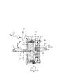
- FIG. 1 is a cross-sectional view schematically showing a centrifugal clutch according to a first embodiment of the invention.
- FIG. 1 shows a cross section including the rotation axis Ax of the centrifugal clutch.
- Also shown in FIG. 1 are part of the engine EG, part of the transmission MT and the clutch lever LV.
- part of the boundary lines of a plurality of members that move together is omitted, and common hatching is given.
- a centrifugal clutch 10 shown in FIG. 1 is a component that transmits rotational driving force of an engine EG, which is a power source, to a transmission MT. More specifically, the centrifugal clutch 10 has a connected state in which the rotational driving force of the engine EG is transmitted to the transmission MT, and a released state in which transmission of the rotational driving force is disconnected. The centrifugal clutch 10 switches between a connected state and a released state. The centrifugal clutch 10 also has a so-called half-clutch state in which part of the rotational driving force of the engine EG is transmitted. However, in this specification, for the sake of clarity, unless otherwise specified, the state in which the engagement of the friction plates is completed will be described as the "connected state.”
- Centrifugal clutch 10 is a multi-plate clutch.
- the centrifugal clutch 10 includes a first rotating member 111, a second rotating member 112, a plurality of first friction plates 113, a plurality of second friction plates 114, a first pressure plate 115, and a second elastic body 116. , and a second pressure plate 117 .
- Centrifugal clutch 10 also includes movement range restricting portion 118 , first elastic body 119 , operating force transmission member 121 , first pressure plate driving portion 122 , first weight 123 , and relative movement mechanism 130 . Prepare.
- the first rotating member 111 is a member that rotates by receiving the rotational driving force of the engine EG.
- the first rotating member 111 is, for example, a clutch housing.
- the first rotating member 111 is configured to rotate by receiving a rotational driving force from a crankshaft CL, which is the output shaft of the engine EG.
- the first rotating member 111 has a clutch input gear 111a.
- the clutch input gear 111a is engaged with a crank gear G provided on the crankshaft CL.
- the first rotating member 111 rotates together with the crankshaft CL of the engine EG. Due to the gear ratio between the clutch input gear 111a and the crank gear G, the first rotating member 111 rotates at a speed lower than the speed of the crankshaft CL.
- the second rotating member 112 is provided rotatably relative to the first rotating member 111 .
- the first rotating member 111 and the second rotating member 112 are configured to rotate about a common rotation axis Ax.
- the second rotating member 112 is, for example, a clutch boss.
- the first friction plate 113 is configured to rotate integrally with the first rotating member 111 .
- the first friction plate 113 functions as a drive plate.
- the second friction plate 114 rotates integrally with the second rotating member 112 .
- the second friction plate 114 functions as a driven plate.
- Each of the first friction plate 113 and the second friction plate 114 is an annular plate.
- the first friction plates 113 and the second friction plates 114 are alternately arranged side by side.
- the first pressure plate 115 is a member that presses one of the first friction plate 113 and the second friction plate 114 against the other friction plate in a pressing direction P parallel to the rotation axis Ax.
- the first pressure plate 115 is an annular plate.
- the first pressure plate 115 rotates integrally with the first rotating member 111 .
- the first pressure plate 115 is movable relative to the first rotating member 111 in the direction of the rotation axis Ax.
- the first pressure plate 115 presses the first friction plate 113 and the second friction plate 114 in the pressing direction P.
- the rotational driving force of the first friction plate 113 is transmitted to the second friction plate 114 by the friction between the first friction plate 113 and the second friction plate 114 . That is, the first friction plate 113 and the second friction plate 114 are engaged with each other.
- the second elastic body 116 is a member attached to the first rotating member 111 .
- the second elastic body 116 is composed of, for example, an annular disc spring. A portion of the second elastic body 116 is fixed to the first rotating member 111 .
- the second elastic body 116 is provided so as to rotate integrally with the first rotating member 111 .
- the second elastic body 116 urges the first pressure plate 115 in the pressing direction P. As shown in FIG. A second pressure plate 117 and a first weight 123 are interposed between the second elastic body 116 and the first pressure plate 115 .
- the second pressure plate 117 is provided so as to rotate integrally with the first rotating member 111 .
- the second pressure plate 117 is provided so as to be relatively movable in the pressing direction P or the releasing direction R with respect to the first rotating member 111 .
- the second pressure plate 117 is biased by the second elastic body 116 .
- the second pressure plate 117 transmits the biasing force in the pressing direction P from the second elastic body 116 to the first pressure plate 115 .
- the movement range restricting portion 118 is configured to restrict the range of movement of the second pressure plate 117 in the pressing direction P.
- the movement range restricting portion 118 is, for example, a step provided on the first rotating member 111 .
- the moving range restricting portion 118 cannot move in the pressing direction P beyond the position where it hits the moving range restricting portion 118 .
- the first elastic body 119 biases the first pressure plate 115 in the release direction R. As shown in FIG. The release direction R is opposite to the pressing direction P.
- the first elastic body 119 is not interposed between the first pressure plate 115 and the first friction plate 113 and the second friction plate 114 .
- First elastic body 119 , first friction plate 113 and second friction plate 114 are mechanically connected in parallel to first pressure plate 115 .
- the first elastic body 119 is configured to release the centrifugal clutch 10 when the rotational speed of the crankshaft CL is in a relatively low speed range such as idling speed.
- the first elastic body 119 is composed of, for example, a coil spring.
- the centrifugal clutch 10 operates according to the operation of the clutch lever LV.
- the operating force transmission member 121 is configured to displace the second pressure plate 117 in the release direction R upon receiving an operating force generated by operating the clutch lever LV.
- the operating force transmission member 121 displaces the second pressure plate 117 in the release direction R against the pressing force of the second elastic body 116 .
- the first pressure plate driving section 122 is provided on the second pressure plate 117, for example.
- the first pressure plate driving portion 122 is provided on a surface facing the first pressure plate 115 .
- the first pressure plate driving portion 122 is configured to function as a cam surface.
- the first pressure plate driving portion 122 is formed so that the distance between the second pressure plate 117 and the first pressure plate 115 becomes smaller toward the outer side in the radial direction.
- the outward direction is the direction away from the rotation axis Ax.
- First weight 123 is provided between first pressure plate 115 and second pressure plate 117 .
- the first weight 123 rotates integrally with the first rotating member 111 and the first pressure plate 115 . More specifically, first weight 123 rotates integrally with first pressure plate 115 and second pressure plate 117 .
- the first weight 123 is provided movably in the radial direction with respect to the first rotating member 111 and the first pressure plate 115 . More specifically, the first weight 123 is provided movably in the radial direction with respect to the first pressure plate 115 and the second pressure plate 117 .
- FIG. 1 shows the stopped state or idling state of the engine EG. When the engine EG is stopped, the first weight 123 is not rotating.
- the relative movement mechanism 130 moves the operating force transmitting member 121 relative to the second pressure plate 117 so as to reduce or eliminate the gap between the operating force transmitting member 121 and the second pressure plate 117 .
- the relative movement mechanism 130 is a mechanism that moves the operating force transmission member 121 without using an actuator.
- Relative movement mechanism 130 is interposed between operating force transmission member 121 and second pressure plate 117 .
- Relative movement mechanism 130 is configured to move operating force transmission member 121 relative to second pressure plate 117 when first weight 123 moves second pressure plate 117 in release direction R.
- the relative movement mechanism 130 moves the operating force transmitting member 121 relative to the second pressure plate 117 so as to reduce or eliminate the gap between the operating force transmitting member 121 and the second pressure plate 117.
- the relative movement mechanism 130 moves the operating force transmission member 121 relatively to the second pressure plate 117. Move in the pressing direction P.
- the relative movement mechanism 130 has a second weight 131 and a first cam portion 132 .
- the second weight 131 receives rotational driving force from the second pressure plate 117 and rotates integrally with the first rotating member 111 and the second pressure plate 117 around the rotation axis Ax.
- the second weight 131 is provided movably in the radial direction with respect to the second pressure plate 117 .
- the second weight 131 is configured to move outward due to the centrifugal force of rotation.
- the outward movement of the second weight 131 moves the relative movement mechanism 130 between the operating force transmission member 121 and the second pressure plate 117 . in the direction of the rotation axis Ax.
- the relative movement mechanism 130 has a displacement member 134 .
- the displacement member 134 rotates together with the second pressure plate 117 and the second weight 131 and is relatively displaceable with respect to the second pressure plate 117 in the direction of the rotation axis Ax.
- the relative movement mechanism 130 also has a third elastic body 133 that biases the second weight 131 so as to restrain the outward movement of the second weight 131 .
- the third elastic body 133 is shown only in FIG. 1 and is omitted from the rest of the drawings.
- the displacement member 134 has a shaft 134a to which the operating force from the operating force transmission member 121 is transmitted, and a washer portion 134b fixed to the shaft 134a and extending radially from the shaft 134a.
- the washer portion 134b receives the operating force transmitted from the operating force transmission member 121 by the shaft 134a, and transmits the operating force from the washer portion 134b to the second weight 131.
- the first cam portion 132 is provided on the second pressure plate 117 .
- the first cam portion 132 is a slope.
- the first cam portion 132 is formed such that the distance to the operating force transmission member 121 in the rotation axis direction A decreases toward the outside.
- FIG. 1 shows the state of the centrifugal clutch 10 when the engine EG is stopped or idling. That is, FIG. 1 shows the state of the centrifugal clutch 10 when the vehicle is stopped. FIG. 1 shows the case where no external force acts on the centrifugal clutch 10 .
- the second elastic body 116 urges the second pressure plate 117 in the pressing direction P. As shown in FIG. The second pressure plate 117 pushes the first weight 123 in the pressing direction P. As shown in FIG. The first weight 123 pushes the first pressure plate 115 in the pressing direction P. As shown in FIG. A range in which the second pressure plate 117 can move in the pressing direction P is restricted by a movement range restricting portion 118 .
- FIG. 2 is a cross-sectional view explaining the state of the centrifugal clutch when the crankshaft is rotating.
- Each part in FIG. 2 is the same as each part in FIG. Therefore, here, the parts different from those in FIG. 1 will mainly be described with reference numerals, and the reference numerals will be omitted for other parts.
- the first weight 123 When the first rotating member 111 rotates due to the rotational driving force of the engine EG, the first weight 123 receives the centrifugal force of the rotation of the first rotating member 111 and moves outward along the first pressure plate driving portion 122 . move to More specifically, when the first weight 123 rotates at such a speed as to move outward against the force of the first elastic body 119, the first weight 123 moves outward. More specifically, when the first weight 123 rotates at a speed greater than the idle speed, the first weight 123 moves outward. The first weight 123 moves outward along the first pressure plate driving portion 122 to move the first pressure plate 115 in the pressing direction P against the biasing force of the first elastic body 119. .
- the first pressure plate 115 presses the first friction plate 113 or the second friction plate 114 in the pressing direction P when the first weight 123 is at the connection position L2. This causes the first friction plate 113 and the second friction plate 114 to engage with each other.
- the centrifugal clutch 10 is connected by moving the first weight 123 to the connection position L2.
- the connection position L2 is the position of the first weight 123 when the non-worn first friction plate 113 and the second friction plate 114 complete engagement.
- the first weight 123 at the connection position L2 has a margin M for further outward movement.
- FIG. 3 is a cross-sectional view explaining the state of the centrifugal clutch rotating at a higher speed than the state of FIG.
- the first weight 123 moves outward from the connection position L2 by receiving a centrifugal force greater than that corresponding to the connection position L2 (see FIG. 2).
- the first weight 123 moves, for example, to position L3 shown in FIG.
- the first pressure plate 115 cannot move. Therefore, the first weight 123 pushes the second pressure plate 117 in the release direction R by the reaction force pushing the first pressure plate 115 .
- the first weight 123 moves the second pressure plate 117 in the release direction R against the biasing force of the second elastic body 116 .
- the first weight 123 moves the second pressure plate 117 in the release direction R while pressing the first pressure plate 115 in the pressing direction P. Therefore, the connected state of the centrifugal clutch 10 is maintained.
- the thickness of the first friction plates 113 and the second friction plates 114 in the rotation axis direction A decreases.
- the first weight 123 moves to the connection position L2 shown in FIG. 2, that is, the connection position L2 where the connection is completed before being worn, the engagement between the first friction plate 113 and the second friction plate 114 will not occur. does not complete. In other words, the connection becomes incomplete.
- the first weight 123 of the centrifugal clutch 10 has a margin M for further outward movement at the connection position L2 shown in FIG. Therefore, when the first friction plate 113 and the second friction plate 114 wear, the first weight 123 can move outward from the connecting position L2 shown in FIG. Thereby, the engagement between the worn first friction plate 113 and the second friction plate 114 can be completed. Therefore, even if wear occurs, the connected state can be achieved without manual operation such as adjustment of screws or the like, and without complicated control by an electric device.
- FIG. 4 is a diagram explaining how the centrifugal clutch 10 in the state of FIG. 2 is put into the released state by operating the clutch lever LV.
- the operating force transmission member 121 When the centrifugal clutch 10 is in the engaged state, the operating force transmission member 121 receives the operating force from the clutch lever LV and displaces the second pressure plate 117 in the release direction R. The operating force transmission member 121 pushes the second pressure plate 117 in the release direction R via the relative movement mechanism 130 . The second pressure plate 117 moves in the release direction R together with the operating force transmission member 121 and the relative movement mechanism 130 . However, the relative movement mechanism 130 rotates relative to the operating force transmission member 121 . The operating force transmission member 121 displaces the second pressure plate 117 against the pressing force of the second elastic body 116 by operating force from the clutch lever LV.
- the centrifugal clutch 10 is released. That is, the centrifugal clutch 10 is released by operating the clutch lever LV.
- the engaged state caused by the centrifugal force and the released state caused by the operation of the clutch lever LV are realized.
- Relative movement mechanism 130 moves operating force transmission member 121 to second pressure plate 117 when first weight 123 moves outward from connection position L2 to move second pressure plate 117 in release direction R. Move relative to The relative movement mechanism 130 moves the operating force transmitting member 121 so as to reduce or eliminate the gap generated between the operating force transmitting member 121 and the second pressure plate 117 .
- the rotation causes the second weight 131 of the relative movement mechanism 130 to move outward as shown in FIG.
- the relative movement mechanism 130 moves the operating force transmission member 121 in the pressing direction P relative to the second pressure plate 117 .
- the displacement member 134 is pushed in the pressing direction P relative to the second pressure plate 117 by the second weight 131 .
- the displacement member 134 of the relative movement mechanism 130 pushes the operating force transmission member 121 in the pressing direction P.
- the length in the rotation axis direction A from the operating force transmission member 121 to the second pressure plate 117 is extended.
- FIG. 5 is a sectional view showing a reference example without a relative movement mechanism as a comparison with this embodiment.
- FIG. 5 shows the condition of centrifugal clutch 90 rotating at a speed equivalent to the condition of FIG.
- the first weight 923 moves to position L3 by receiving the same centrifugal force as in the state shown in FIG.
- the second pressure plate 917 is pushed by the first weight 923 and moves in the release direction R.
- a gap S is created between the second pressure plate 917 and the operating force transmission member 921 .
- the gap S increases as the first weight 923 moves outward from the connection position (see L2 in FIG. 2).
- the amount of operation of the clutch lever LV from the non-operating position indicated by the solid line in FIG. 5 to the released position indicated by the broken line increases.
- the amount of operation of the clutch lever LV from the non-operated position to the released position corresponds to play of the clutch lever LV.
- the size of the gap S when the first weight 923 is at the connection position (see L2 in FIG. 2) and the gap S when the first weight 923 moves to the position L3 They differ in size. That is, the amount of play of the clutch lever LV differs between when the first weight 923 is at the connected position (see L2 in FIG. 2) and when it is at the position L3.
- the play of the clutch lever LV is not limited to the connection position L2, but is also the position where the repulsive force due to the biasing force of the second elastic body 916 is generated when the clutch lever LV is operated.
- the position at which the second elastic body 916 gives a response during the operation of the clutch lever LV depends on whether the first weight 923 is at the connected position (see L2 in FIG. 2) or at the position L3. different.
- the relative movement mechanism 130 of the embodiment of the present invention shown in FIGS. 1 to 4 moves the operating force transmission member 121 to the second pressure plate 117 when the first weight 123 moves the second pressure plate 117 in the release direction R.
- Move relative to The relative movement mechanism 130 relatively moves the operating force transmitting member 121 so as to reduce or eliminate the gap generated between the operating force transmitting member 121 and the second pressure plate 117 . Therefore, it is possible to suppress the change in the engagement position of the clutch lever LV due to the rotation speed.
- centrifugal clutch 10 can suppress changes in the operating position of the clutch lever LV caused by wear without adjusting screws or the like. That is, the centrifugal clutch 10 itself can suppress changes in the operating position of the clutch lever LV due to wear.
- the centrifugal clutch 10 can suppress the influence of wear of the first friction plate 113 and the second friction plate 114 on the connection state, and can also reduce the influence of the rotation speed on the connection position.
- FIG. 6 is a graph showing the relationship between the rotation speed of the first rotating member and the displacement amount of the first weight of the centrifugal clutch according to the second embodiment of the invention.
- the configuration of the centrifugal clutch 10 in this embodiment is the same as the first embodiment shown in FIGS. 1 to 4, and each elastic body has specific characteristics. Accordingly, the configuration of each part is given the same reference numerals and will be described with reference to FIGS. 1 to 4.
- FIG. 1 is the same reference numerals and will be described with reference to FIGS. 1 to 4.
- the horizontal axis of the graph indicates the rotational speed of the first rotating member 111 .
- the rotational speed of the first rotating member 111 is determined by the gear ratio between the clutch input gear 111a and the crank gear G with respect to the rotational speed of the crankshaft CL.
- the first weight 123 rotates at the same speed as the first rotating member 111 .
- the second weight 131 rotates at the same speed as the first rotating member 111 .
- the vertical axis of the graph indicates the amount of displacement of the first weight 123 .
- the vertical axis indicates positions L1, L2, and L3 of the first weight 123 shown in FIGS.
- the graph also shows the length in the rotation axis direction A from the operating force transmission member 121 to the second pressure plate 117 .
- This length is represented by, for example, the shortest distance between the operating force transmission member 121 and the second pressure plate 117 in the direction A of the rotation axis.
- the length can also be represented by the longest distance in the rotation axis direction A, for example.
- the first rotating member 111 rotates at a speed smaller than or equal to the speed N1.
- This rotational speed is, for example, the idling state of the engine EG.
- the first weight 123 is at the initial position L1 shown in FIG.
- the speed N1 is the speed at which the centrifugal force applied to the first weight 123 and the biasing force of the first elastic body 119 are balanced.
- the accelerator operation increases the rotation speed of the first rotating member 111 and exceeds the speed N1
- the first weight 123 moves outward against the biasing force of the first elastic body 119 .
- the centrifugal clutch 10 is connected. The vehicle starts running.
- the first weight 123 resists the biasing force of the second elastic body 116 and moves outward from the connection position L2.
- the first weight 123 stops at position L3 (see also FIG. 3).
- the speed N2 of the second weight 131 at which the centrifugal force applied to the second weight 131 and the biasing force of the third elastic body 133 that suppresses the movement of the second weight 131 are balanced is due to the centrifugal force applied to the second weight 131. is smaller than the speed N3 at which the force received by the second pressure plate 117 and the biasing force of the second elastic body 116 are balanced.
- the second weight 131 of the relative movement mechanism 130 attempts to move outward against the biasing force of the third elastic body 133.
- Relative movement mechanism 130 attempts to move operating force transmission member 121 relative to second pressure plate 117 .
- no gap is generated between the second pressure plate 117 and the operating force transmission member 121 . Therefore, the operating force transmission member 121 does not move and only presses in the pressing direction P. As shown in FIG.
- the relative movement mechanism 130 moves the operating force transmission member 121 relative to the second pressure plate 117 so as to reduce or eliminate a gap (for example, S in FIG. 5) that may occur at this time.
- the relative movement mechanism 130 moves the operating force transmission member 121 relative to the second pressure plate 117 when the rotation speed of the first rotating member 111 exceeds the speed N3. It is possible to move Therefore, a gap (for example, S in FIG. 5) is less likely to occur in a wide speed range.
- FIG. 7 is a cross-sectional view schematically showing a centrifugal clutch according to a third embodiment of the invention.
- a relative movement mechanism 330 of the centrifugal clutch 30 of FIG. 7 has a one-way slide mechanism 340 .
- the relative movement mechanism 330 has bearings 350 .
- the bearing 350 rotatably supports the one-way slide mechanism 340 with respect to the second pressure plate 117 .
- One-way slide mechanism 340 is interposed between second pressure plate 117 and operating force transmission member 121 .
- the one-way slide mechanism 340 is configured to be freely extendable when the second pressure plate 117 is pushed by the first pressure plate 115 and moves in the release direction R. Further, the one-way slide mechanism 340 is configured to restrict contraction when the operating force transmission member 121 receives an operating force and moves in the release direction R.
- one-way slide mechanism 340 includes slide housing 341 , ratchet 342 , ratchet spring 343 , extension spring 344 and transmission member extension 345 .
- the second rotating member 112 is provided with a releasing portion 112a.
- Slide housing 341 is rotatably supported by second pressure plate 117 via bearing 350 .
- the slide housing 341 moves in the rotational axis direction A together with the second pressure plate 117 .
- the slide housing 341 is cylindrical with a bottom.
- the transmission member extension 345 is housed in the slide housing 341 .
- the transmission member extension portion 345 is a member that extends from the operating force transmission member 121 .
- a wedge-shaped ratchet 342 is provided between the inner surface of the slide housing 341 and the operating force transmission member 121 .
- the ratchet 342 is pushed between the slide housing 341 and the operating force transmission member 121 by being biased by the ratchet spring 343 . Movement of the operating force transmission member 121 with respect to the slide housing 341 is blocked.
- Other configurations in this embodiment are the same as those in the first embodiment shown in FIG. Therefore, common elements are denoted by the same reference numerals as in the first embodiment, and differences from the first embodiment will be mainly described.
- FIG. 8 is a cross-sectional view explaining the state of the centrifugal clutch rotating at a higher speed than the state of FIG.
- the first weight 123 moves the second pressure plate 117 in the release direction R while moving outward from the connection position L2.
- the one-way slide mechanism 340 can be freely extended. Accordingly, the one-way slide mechanism 340 moves the operating force transmission member 121 relative to the second pressure plate 117 .
- the one-way slide mechanism 340 moves the operating force transmitting member 121 so as to reduce or eliminate the gap in the rotational axis direction A between the operating force transmitting member 121 and the second pressure plate 117 . More specifically, the transmission member extension 345 biased in the pressing direction P by the extension spring 344 is pushed out toward the operating force transmission member 121 .
- the operating force transmission member 121 moves in the pressing direction P when the clutch lever LV is released from operation.
- the ratchet 342 keeps the one-way slide mechanism 340 from being deformed. Therefore, the entire one-way slide mechanism 340 moves in the pressing direction P together with the operating force transmission member 121 .
- Centrifugal clutch 30 returns to the engaged state.
- the ratchet 342 hits the release portion 112a. The restriction by the ratchet 342 is released when the ratchet 342 hits the release portion 112a.
- FIG. 9 is a cross-sectional view schematically showing a centrifugal clutch according to a fourth embodiment of the invention.
- the second pressure plate 117 of the centrifugal clutch 10 in FIG. 9 has a second cam portion 141.
- the second weight 131 receives torque from the second pressure plate 117 to accelerate and decelerate its rotation.
- the second cam portion 141 is formed on the second pressure plate 117 so as to transmit deceleration torque to the second weight 131 and move the second weight 131 radially inward.
- the second cam portion 141 of the second pressure plate 117 of the present embodiment is configured by a plane having a normal that obliquely intersects the circumference of the second pressure plate 117 centered on the rotation axis Ax. .
- the plane of the second cam portion 141 obliquely intersects with the radial direction.
- the second weight 131 of the relative movement mechanism 130 moves outward due to the centrifugal force that the second weight 131 receives.
- the second cam portion 141 applies radially inward force to the second weight 131 when decelerating the rotation. Therefore, even if frictional force is generated between the second weight 131 and the first cam portion 132, the second weight 131 tends to return radially inward when the rotation is decelerated.
- FIG. 10(a) shows the state in which the engine EG is stopped.
- the second weight 131 of the centrifugal clutch 10 of this embodiment is composed of two weights 131a and 131b.
- the two weights 131a and 131b are coupled by a third elastic body 133 and urged inward by the urging force C2 of the third elastic body 133.
- No centrifugal force is generated in the second weight 131 (131a, 131b) when the rotation is stopped.
- the first weight 123 is at the initial position L1 as shown in FIG.
- a second cam portion 141 and a wall 142 are formed on the second pressure plate 117 .
- the second pressure plate 117 When the rotation starts, the second pressure plate 117 also rotates via the first rotating member 111. At this time, the second weight 131 receives a force F1 in the direction of rotation of the second pressure plate 117 by the wall 142 formed on the second pressure plate 117 and rotates in the same direction as the second pressure plate 117 .
- the second weight 131 (131a, 131b) rotates, the second weight 131 generates a centrifugal force C1.
- the magnitude of the centrifugal force C1 generated in the second weight 131 moves outward against the biasing force C2 of the third elastic body 133, thereby exerting an operating force on the first cam portion 132. less than the degree that gives Therefore, when the engine EG is in the idling operation state, the second weights 131 (131a, 131b) do not move from the positions shown in FIG. 10(a).
- FIG. 10(b) shows the state of the centrifugal clutch 10 when the crankshaft CL is rotating.
- the centrifugal force C1 that the second weight 131 receives increases, as shown in FIG. 10(b).
- the two weights 131a and 131b constituting the second weight 131 move outward along the wall 142 against the biasing force C2 of the third elastic body 133 respectively.
- the first weight 123 moves from the initial position L1 as shown in FIG. 1 to the position L3 as shown in FIG. It moves further outward along the 1 cam portion 132 .
- the second weight 131 pushes the operating force transmission member 121 in the pressing direction P relative to the second pressure plate 117 via the displacement member 134 (see FIG. 9). At this time, a frictional force is generated between the second weight 131 and the first cam portion 132 and the displacement member 134 .
- FIGS. 10(c) and (d) show the state of the centrifugal clutch 10 in which the crankshaft CL is decelerated from the state of FIG. 10(b).
- the second pressure plate 117 also decelerates.
- the second cam portion 141 contacts the second weight 131 to transmit deceleration torque.
- the second weight 131 leaves the wall 142 of the second pressure plate 117 and contacts the second cam portion 141 .
- the second weight 131 applies a rotating force F2 to the second cam portion 141 and receives a reaction force F3.
- the centrifugal force applied to the two weights 131a and 131b becomes smaller than the state shown in FIG. 10(b).
- an inward force acts on the two weights 131a and 131b due to the biasing force C2 of the third elastic body 133.
- the second weight 131 may become difficult to return inward due to the frictional force generated between the first cam portion 132 and the displacement member 134 .
- the second weight 131 in this embodiment receives a reaction force F3 from the second cam portion 141, as shown in FIG. 10(c). As a result, the two weights 131a and 131b move inward along the second cam portion 141, respectively.
- the two weights 131a and 131b are released from the frictional force generated between the first cam portion 132 and the displacement member 134, and the biasing force of the third elastic body 133 causes the weights 131a and 131b to move inward.
- the second weight 131 that has received the centrifugal force moves outward from its original position, it easily returns to its original position when the centrifugal force decreases. Therefore, displacement of the second pressure plate 117 in the direction of the rotation axis Ax caused by the first weight 123 receiving the centrifugal force moving outward from the connection position is likely to return when the centrifugal force is reduced. Therefore, it is possible to more precisely suppress the change in the connection position between when the vehicle starts running and when the vehicle is running. Therefore, for example, a change in connection position between when the vehicle starts running and when the vehicle is running can be easily suppressed.
- FIG. 11 is a diagram showing an example of the centrifugal clutch of the embodiment described above.
- 11(a) is a cross-sectional view in the rotation axis direction
- FIG. 11(b) is a view of the relative movement mechanism 130 in FIG.
- Elements of the centrifugal clutch shown in FIG. 11 are assigned the same reference numerals as in the first to fourth embodiments.
- the first cam portion 132 in this embodiment is provided on the displacement member 134 . More specifically, a portion of the peripheral edge of the washer portion 134b of the displacement member 134 is formed thick.
- the first cam portion 132 is composed of an inclined surface of the thick portion of the washer portion 134b.
- the second cam portion 141 is provided on the second pressure plate 117 . More specifically, the second pressure plate 117 is provided with a hole 143 penetrating in the rotational axis direction A. As shown in FIG. A second cam portion 141 and a wall 142 are provided in the hole 143 .
- the second weight 131 has a protrusion 131c. Projection 131 c is received in hole 143 of second pressure plate 117 .
- the projecting portion 131 c functions as a cam follower that receives the action of the second cam portion 141 .
- the second weight 131 assumes a position rotated relative to the second pressure plate 117 .
- the reference line Y1 between the two weights 131a, 131b rotates as indicated by Y2.
- the projecting portion 131c of the second weight 131 contacts the second cam portion 141 and moves inward along the second cam portion 141 .
- the second weight 131 moves inward due to the biasing force of the third elastic body 133 .
- the inward movement of the second weight 131 is promoted by the action of the second cam portion 141 .
- the position X3 of the inwardly moved second weight 131 (131a) is indicated by a two-dot chain line
- the position X4 of the projecting portion 131c is also indicated by a two-dot chain line.
- the second weight 131 rotates relative to the second pressure plate 117 in a direction opposite to the direction in which the second pressure plate 117 rotates and returns to its original position. return. At this time, the projection 131c of the second weight 131 contacts the wall 142. As shown in FIG. After that, when the rotational speed further increases, the projection 131c of the second weight 131 moves outward along the wall 142 .
- FIG. 12 is a side view showing a straddle-type vehicle to which the centrifugal clutch of the embodiment is applied.
- the straddle-type vehicle 1 shown in FIG. 12 is also one embodiment of the present invention.
- a straddle-type vehicle 1 shown in FIG. 12 is a motorcycle.
- a straddle-type vehicle 1 includes an engine EG, a transmission MT, and centrifugal clutches (10, 30). Centrifugal clutches (10, 30) transmit rotational driving force of engine EG to transmission MT.
- the transmission MT is operated by the foot of the driver of the straddle-type vehicle 1 .
- the straddle-type vehicle 1 also includes a clutch lever LV and drive wheels 5 .
- the clutch lever LV is operated by the driver of the straddle-type vehicle 1 .
- Centrifugal clutches (10, 30) switch between a connected state in which rotational driving force is transmitted from the engine EG to the transmission MT and a released state in which the transmission is released, in response to operation of a clutch lever LV.
- the centrifugal clutch (10, 30) also switches between a connected state and a released state according to the rotation speed of the engine EG.
- the transmission MT transmits rotational driving force to the drive wheels 5 .
- the straddle-type vehicle 1 travels by driving the driving wheels 5 .
Landscapes
- Engineering & Computer Science (AREA)
- General Engineering & Computer Science (AREA)
- Mechanical Engineering (AREA)
- One-Way And Automatic Clutches, And Combinations Of Different Clutches (AREA)
Abstract
Le but de la présente invention est d'utiliser un embrayage centrifuge susceptible de supprimer spontanément les effets de friction sur un état de liaison d'une plaque de friction et également de supprimer spontanément une variation de position de liaison due à la vitesse de rotation. L'embrayage centrifuge comprend : une première plaque de friction ; une seconde plaque de friction ; une première plaque de pression ; un second corps élastique ; une seconde plaque de pression ; une unité de restriction de plages de mouvement ; un premier corps élastique ; un élément de transmission de forces d'actionnement ; une première unité d'entraînement de plaques de pression ; et un premier poids. Le premier poids se déplace jusqu'à une position de liaison où s'achève l'engrènement de la première plaque de friction et de la seconde plaque de friction et où il existe une marge de manœuvre permettant un déportement supplémentaire vers l'extérieur. L'embrayage centrifuge comprend en outre un mécanisme de mouvement relatif et lorsque le premier poids se déporte davantage vers l'extérieur que la position de liaison, en provoquant ainsi le déplacement de la seconde plaque de pression selon un sens de libération, le mécanisme provoque le déplacement de l'élément de transmission de forces d'actionnement par rapport à la seconde plaque de pression, afin de réduire voire de supprimer la formation d'un espace entre l'élément de transmission de forces d'actionnement et la seconde plaque de pression.
Priority Applications (2)
| Application Number | Priority Date | Filing Date | Title |
|---|---|---|---|
| JP2023500754A JP7446516B2 (ja) | 2021-02-18 | 2022-02-08 | 遠心クラッチ、及びストラドルドビークル |
| TW111105246A TWI812005B (zh) | 2021-02-18 | 2022-02-14 | 離心式離合器、及跨坐型車輛 |
Applications Claiming Priority (2)
| Application Number | Priority Date | Filing Date | Title |
|---|---|---|---|
| JP2021-024215 | 2021-02-18 | ||
| JP2021024215 | 2021-02-18 |
Publications (1)
| Publication Number | Publication Date |
|---|---|
| WO2022176693A1 true WO2022176693A1 (fr) | 2022-08-25 |
Family
ID=82930858
Family Applications (1)
| Application Number | Title | Priority Date | Filing Date |
|---|---|---|---|
| PCT/JP2022/004826 WO2022176693A1 (fr) | 2021-02-18 | 2022-02-08 | Embrayage centrifuge et véhicule à selle |
Country Status (3)
| Country | Link |
|---|---|
| JP (1) | JP7446516B2 (fr) |
| TW (1) | TWI812005B (fr) |
| WO (1) | WO2022176693A1 (fr) |
Citations (5)
| Publication number | Priority date | Publication date | Assignee | Title |
|---|---|---|---|---|
| JPS54140051A (en) * | 1978-04-24 | 1979-10-30 | Yamaha Motor Co Ltd | Centrifugal clutch |
| US5377803A (en) * | 1992-05-06 | 1995-01-03 | Fichtel & Sachs Ag | Pressure plate arrangement for a motor vehicle friction clutch |
| US5638935A (en) * | 1995-10-26 | 1997-06-17 | Fehring; Thomas C. | Centrifugal clutch |
| JP2009197991A (ja) * | 2008-02-25 | 2009-09-03 | Yamaha Motor Co Ltd | 摩擦クラッチ |
| JP2012031901A (ja) * | 2010-07-29 | 2012-02-16 | Honda Motor Co Ltd | クラッチ装置 |
Family Cites Families (2)
| Publication number | Priority date | Publication date | Assignee | Title |
|---|---|---|---|---|
| US8210333B2 (en) * | 2007-06-29 | 2012-07-03 | Yamaha Hatsudoki Kabushiki Kaisha | Clutch and vehicle having clutch |
| JP2009197823A (ja) * | 2008-02-19 | 2009-09-03 | Yamaha Motor Co Ltd | 電子制御式変速装置およびそれを備えた鞍乗型車両 |
-
2022
- 2022-02-08 JP JP2023500754A patent/JP7446516B2/ja active Active
- 2022-02-08 WO PCT/JP2022/004826 patent/WO2022176693A1/fr active Application Filing
- 2022-02-14 TW TW111105246A patent/TWI812005B/zh active
Patent Citations (5)
| Publication number | Priority date | Publication date | Assignee | Title |
|---|---|---|---|---|
| JPS54140051A (en) * | 1978-04-24 | 1979-10-30 | Yamaha Motor Co Ltd | Centrifugal clutch |
| US5377803A (en) * | 1992-05-06 | 1995-01-03 | Fichtel & Sachs Ag | Pressure plate arrangement for a motor vehicle friction clutch |
| US5638935A (en) * | 1995-10-26 | 1997-06-17 | Fehring; Thomas C. | Centrifugal clutch |
| JP2009197991A (ja) * | 2008-02-25 | 2009-09-03 | Yamaha Motor Co Ltd | 摩擦クラッチ |
| JP2012031901A (ja) * | 2010-07-29 | 2012-02-16 | Honda Motor Co Ltd | クラッチ装置 |
Also Published As
| Publication number | Publication date |
|---|---|
| TW202238014A (zh) | 2022-10-01 |
| JPWO2022176693A1 (fr) | 2022-08-25 |
| JP7446516B2 (ja) | 2024-03-08 |
| TWI812005B (zh) | 2023-08-11 |
Similar Documents
| Publication | Publication Date | Title |
|---|---|---|
| JP6843634B2 (ja) | クラッチ装置及び自動変速機 | |
| JP5444153B2 (ja) | クラッチ装置 | |
| MX2014006648A (es) | Montaje de polea con un mecanismo de desacoplamiento. | |
| JP2016211688A5 (fr) | ||
| CN105247235A (zh) | 具有齿轮推力激活装置的楔式单向离合器 | |
| JP6779891B2 (ja) | クラッチ装置、及びクラッチ装置を備えるパワートレーン | |
| WO2012053281A1 (fr) | Dispositif d'embrayage | |
| WO2019044951A1 (fr) | Dispositif de transmission de puissance | |
| WO2019044950A1 (fr) | Dispositif de transmission d'énergie | |
| WO2022176693A1 (fr) | Embrayage centrifuge et véhicule à selle | |
| WO2020116508A1 (fr) | Dispositif de transmission de puissance | |
| JP2010216501A (ja) | 自動変速機のピストン構造 | |
| JP7161285B2 (ja) | クラッチ装置 | |
| WO2009093529A1 (fr) | Dispositif d'embrayage pour motocyclette | |
| KR101448394B1 (ko) | 자동화 수동변속기의 클러치 액추에이터 | |
| JP4566797B2 (ja) | クラッチ装置 | |
| US5833041A (en) | Clutch operating mechanism | |
| WO2006067399A1 (fr) | Embrayage à friction à prise avec ressorts diaphragme multiples sur plusieurs phases | |
| US6790161B2 (en) | Clutch for automobiles | |
| WO1998040638A1 (fr) | Embrayage a friction | |
| KR20100067948A (ko) | 역회전 방지기능을 갖춘 변속장치 | |
| JP2009174618A (ja) | クラッチ装置 | |
| USRE38580E1 (en) | Clutch operating mechanism | |
| JP2007211929A (ja) | 前後進切替え機構 | |
| JP5820860B2 (ja) | マルチディスク変速機 |
Legal Events
| Date | Code | Title | Description |
|---|---|---|---|
| 121 | Ep: the epo has been informed by wipo that ep was designated in this application |
Ref document number: 22756014 Country of ref document: EP Kind code of ref document: A1 |
|
| WWE | Wipo information: entry into national phase |
Ref document number: 2023500754 Country of ref document: JP |
|
| NENP | Non-entry into the national phase |
Ref country code: DE |
|
| 122 | Ep: pct application non-entry in european phase |
Ref document number: 22756014 Country of ref document: EP Kind code of ref document: A1 |