WO2022176407A1 - モータ制御装置、モータ駆動装置並びにこれを用いた機器 - Google Patents
モータ制御装置、モータ駆動装置並びにこれを用いた機器 Download PDFInfo
- Publication number
- WO2022176407A1 WO2022176407A1 PCT/JP2021/048765 JP2021048765W WO2022176407A1 WO 2022176407 A1 WO2022176407 A1 WO 2022176407A1 JP 2021048765 W JP2021048765 W JP 2021048765W WO 2022176407 A1 WO2022176407 A1 WO 2022176407A1
- Authority
- WO
- WIPO (PCT)
- Prior art keywords
- motor
- current
- fundamental wave
- wave component
- control device
- Prior art date
- Legal status (The legal status is an assumption and is not a legal conclusion. Google has not performed a legal analysis and makes no representation as to the accuracy of the status listed.)
- Ceased
Links
Images


Classifications
-
- B—PERFORMING OPERATIONS; TRANSPORTING
- B60—VEHICLES IN GENERAL
- B60L—PROPULSION OF ELECTRICALLY-PROPELLED VEHICLES; SUPPLYING ELECTRIC POWER FOR AUXILIARY EQUIPMENT OF ELECTRICALLY-PROPELLED VEHICLES; ELECTRODYNAMIC BRAKE SYSTEMS FOR VEHICLES IN GENERAL; MAGNETIC SUSPENSION OR LEVITATION FOR VEHICLES; MONITORING OPERATING VARIABLES OF ELECTRICALLY-PROPELLED VEHICLES; ELECTRIC SAFETY DEVICES FOR ELECTRICALLY-PROPELLED VEHICLES
- B60L15/00—Methods, circuits, or devices for controlling the traction-motor speed of electrically-propelled vehicles
- B60L15/007—Physical arrangements or structures of drive train converters specially adapted for the propulsion motors of electric vehicles
-
- H—ELECTRICITY
- H02—GENERATION; CONVERSION OR DISTRIBUTION OF ELECTRIC POWER
- H02P—CONTROL OR REGULATION OF ELECTRIC MOTORS, ELECTRIC GENERATORS OR DYNAMO-ELECTRIC CONVERTERS; CONTROLLING TRANSFORMERS, REACTORS OR CHOKE COILS
- H02P27/00—Arrangements or methods for the control of AC motors characterised by the kind of supply voltage
- H02P27/04—Arrangements or methods for the control of AC motors characterised by the kind of supply voltage using variable-frequency supply voltage, e.g. inverter or converter supply voltage
- H02P27/06—Arrangements or methods for the control of AC motors characterised by the kind of supply voltage using variable-frequency supply voltage, e.g. inverter or converter supply voltage using DC to AC converters or inverters
- H02P27/08—Arrangements or methods for the control of AC motors characterised by the kind of supply voltage using variable-frequency supply voltage, e.g. inverter or converter supply voltage using DC to AC converters or inverters with pulse width modulation
- H02P27/12—Arrangements or methods for the control of AC motors characterised by the kind of supply voltage using variable-frequency supply voltage, e.g. inverter or converter supply voltage using DC to AC converters or inverters with pulse width modulation pulsing by guiding the flux vector, current vector or voltage vector on a circle or a closed curve, e.g. for direct torque control
Definitions
- the present invention relates to a motor control device that controls an AC motor, a motor drive device that drives an AC motor at variable speeds, and equipment using the same.
- Synchronous PWM control (see, for example, Patent Document 1) is used to change the PWM carrier frequency and the number of pulses for each electrical angle frequency for high-speed rotation control of the motor.
- a DC bus current detection method (see Patent Documents 2 and 3, for example) that detects a three-phase AC current without using a phase current sensor is used to detect the motor current.
- the PWM carrier frequency changes in synchronization with the electrical angle rotation frequency, and the number of PWM pulses is controlled to be a multiple of 3 (odd number) and 1 pulse. In other words, during high-speed rotation, the number of PWM pulses decreases to a maximum of 1 pulse.
- the DC bus current detection method is a method of reproducing the fundamental wave component of the motor current by distributing the DC bus current detected almost simultaneously according to the combination of PWM pulses to each phase.
- the simultaneity of detection of the DC bus current changes depending on the detection capability of the AD converter of the microcomputer (hereinafter referred to as a microcomputer). In other words, when the motor rotates at high speed, the simultaneity of the DC bus current cannot be ensured, and the reproduction error of the motor current increases.
- the present invention provides a motor control device, a motor drive device, and the like, which can detect the fundamental wave component of the motor current with high accuracy even when the electrical angular frequency is high as in high-speed driving, and can stably control the motor.
- a motor control device a motor drive device, and the like, which can detect the fundamental wave component of the motor current with high accuracy even when the electrical angular frequency is high as in high-speed driving, and can stably control the motor.
- a motor control device generates a control signal for controlling a motor based on a speed command and a detected value of motor current. and a fundamental wave component extracting means for extracting a fundamental wave component of the phase current of the motor detected by the phase current detecting means, wherein the fundamental wave component extracted by the fundamental wave component extracting means is A control signal is created as a detected value of the motor current.
- a motor drive device includes an inverter that drives and controls a motor, and a control section that generates a control signal for controlling the inverter.
- 1 is a motor control device according to the invention
- the equipment according to the present invention is driven by a motor, and the motor is driven by the motor driving device according to the present invention.
- the motor current fundamental wave component can be detected with high accuracy even when the electrical angle frequency is high.
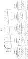
- FIG. 1 is a functional block diagram showing the configuration of a motor drive device that is Embodiment 1.
- FIG. 3 is a waveform diagram showing waveforms of a line voltage and a motor phase current output by an inverter 3;
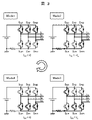
- FIG. 3 is a circuit diagram showing currents flowing through a main circuit portion of the inverter 3;
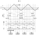
- FIG. 4 is a waveform diagram showing operation waveforms of the motor driving device (inverter 3 and control device section);
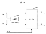
- FIG. 4 is a functional block diagram showing an example of a motor current computing unit that computes a motor current from a detected value of a DC bus current;
- FIG. 3 is a waveform diagram showing waveforms of a line voltage and a motor phase current output by an inverter 3
- FIG. 3 is a circuit diagram showing currents flowing through a main circuit portion of the inverter 3
- FIG. 4 is a waveform diagram showing operation waveforms of the motor driving device (inverter 3 and control device section)
- FIG. 4 is
- FIG. 4 is a waveform diagram showing operation waveforms of the motor driving device when the motor rotates at high speed; The relationship between the rotation speed and the phase difference is shown when the motor is a 4-pole PMSM and the detection interval of the AD converter is 10 ⁇ s.
- 4 is a functional block diagram showing the configuration of a DC bus motor current detector 5 in Embodiment 1.
- FIG. 3 is a functional block diagram showing the configuration of a fundamental wave component extractor 5B to which simple Fourier transform is applied;
- FIG. 2 is a functional block diagram showing the configuration of a fundamental wave component extractor 5B to which a sine wave transfer function is applied;
- FIG. 4 is a waveform diagram showing a motor phase current detected by a DC bus current and a fundamental wave component of the motor current extracted from the motor phase current; 4 is a waveform diagram showing a waveform of a motor current and a waveform of a DC bus current of a motor 4 rotationally driven in Embodiment 1.
- FIG. 1 is an external view showing a schematic configuration of a stick-type vacuum cleaner;
- FIG. 1 is an external view showing a schematic configuration of a drum-type washing machine;
- FIG. 1 is an external view showing a schematic configuration of an electric vehicle;
- FIG. 1 is a configuration diagram showing a schematic configuration of a hybrid turbocharger;
- FIG. 5 is a functional block diagram showing the configuration of a motor drive device that is Embodiment 2;
- FIG. 11 is a functional block diagram showing the configuration of a motor drive device that is Embodiment 3;
- Example 1 will be described using FIGS.
- FIG. 1 is a functional block diagram showing the configuration of a motor drive device that is Embodiment 1 of the present invention.
- the motor driving device of the first embodiment includes an inverter 3 that applies three-phase AC voltages Vu, Vv, and Vw to the motor 4 .
- a permanent magnet synchronous motor (hereinafter referred to as “PMSM”) is applied as the motor 4 in the first embodiment.
- the inverter 3 has an inverter circuit such as a three-phase bridge circuit composed of power semiconductor switching elements (eg, IGBTs and power MOSFETs).
- the inverter circuit converts the input DC voltage from the DC power supply into a three-phase AC voltage by turning on and off the semiconductor switching elements, and outputs this three-phase AC voltage to the motor 4 .
- the control unit for controlling the on/off of the semiconductor switching elements that make up the inverter circuit includes a synchronous PWM converter 2 that creates a pulse width modulation (hereinafter referred to as "PWM") control signal, speed commands ⁇ * and three A vector controller 1 that creates a three-phase voltage command Vuvw based on the phase motor current Iuvw and gives Vuvw to a synchronous PWM converter 2, and a DC bus current IDC in the inverter 3 is detected, and Iuvw is detected from the detected value of IDC. and a DC bus motor current detector 5 that reproduces
- PWM pulse width modulation
- the vector controller 1 employs simple vector control (see Patent Document 4) that does not use a current controller.
- Iq: T is the time constant).
- the d-axis current command Id * which is the current command for the d-axis component in the rotating coordinate system of the motor current, is set to zero.
- the vector controller 1 calculates the d-axis voltage command Vd * and the q-axis voltage command Vd* and the q-axis voltage command using the voltage equation represented by the formula (1) based on the rotation speed command ⁇ r * and the above Iq * and Id * . Compute Vq * .
- R, Lq, Ld, and Ke are the winding resistance, q-axis inductance, d-axis inductance, and induced voltage constant, respectively.
- the vector controller 1 creates a three-phase voltage command Vuvw from Vd * and Vq * by dq/three-phase conversion.
- the period of the carrier wave signal and the period of the sinusoidal command signal (modulated wave signal) are in an integral multiple relationship, and so-called synchronous PWM control is applied to synchronize the phases of both signals (Patent Reference 1).
- Synchronous PWM control generally changes the carrier frequency according to changes in the output frequency of the inverter.
- the number of pulses in one cycle of the PWM control signal is often constant regardless of the inverter output frequency, but the number of pulses may be switched according to the inverter output frequency.
- the number of PWM pulses and the carrier frequency are set for each electrical angular frequency and set to Vuvw.
- a PWM control signal (upper arm) is created according to the carrier frequency.
- the inverter 3 is a DC/AC converter made up of semiconductor switching elements, and generates a three-phase AC voltage (Vu, Vv, Vw) are output as PWM pulses.
- the motor 4 is driven by this PWM pulse.
- the PWM control signal may be given to the semiconductor switching element via the driver circuit.
- the inverter 3 also has a shunt resistor that detects the DC bus current.
- the voltage across the terminals of the shunt resistor is input to the DC bus motor current detector 5 as the DC bus current detection value IDC.
- the DC bus motor current detector 5 extracts the fundamental wave component Iuvw of the motor current based on the detected value IDC of the DC bus current and the PWM control signal (upper arm), and outputs the extracted Iuvw to the vector controller 1. do.
- FIG. 2 is a waveform diagram showing waveforms of the line voltage and the motor phase current output by the inverter 3.
- FIG. 2 is a waveform diagram showing waveforms of the line voltage and the motor phase current output by the inverter 3.
- the rotation speed of the motor 4 is accelerated from 0 rpm to 100,000 rpm.
- the vector controller 1 creates a PWM control signal by asynchronous PWM control at low speeds, but after switching to synchronous PWM control, as the rotation speed increases, the pulse of the PWM control signal per half cycle of the voltage command increases. The number is decreased stepwise from 15 pulses to 1 pulse.
- FIG. 3 is a circuit diagram showing the current flowing through the main circuit section of the inverter 3.
- the motor current can be detected by detecting the DC bus current flowing through the shunt resistor.
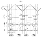
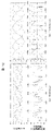
- FIG. 4 is a waveform diagram showing operation waveforms of the motor drive device (inverter 3 and control device section).
- each waveform of the carrier wave signal and the three-phase voltage command Vuvw (modulated wave signal), the waveform of the PWM control signal (upper arm) created based on the carrier signal and the three-phase voltage command Vuvw,
- the waveforms of the three-phase motor currents Iu, Iv, and Iw and the waveform of the DC bus current IDC are shown.
- the points shown in the waveforms of the motor currents Iu and Iw and the DC bus current IDC indicate the timing at which the DC bus motor current detector 5 in the control unit of the inverter 3 detects the DC bus current.
- This detection timing corresponds to, for example, the activation timing of the A/D conversion function provided in the microcomputer that constitutes the control device section.
- the detection timing of the DC bus current is the timing before and after the timing at which the intermediate-phase PWM control signal (pulse) in the three-phase applied voltage command Vuvw (modulation wave signal) changes.
- FIG. 4 shows the timing before and after the timing at which the V-phase PWM control signal changes.
- the DC bus motor current detector 5 detects two-phase motor currents, although the detection timings are different.
- the IDC detects two-phase motor currents (-Iw, Iu) at timings before and after phase A, and based on -Iw and Iu, three-phase motor currents with phase A as a reference. (Iu, Iv, Iw) is calculated. Furthermore, the IDC detects two-phase motor currents (Iu, -Iw) at timings before and after phase B, and based on Iu, -Iw, three-phase motor currents (Iu, Iv, Iw) is calculated.
- the operation modes of the inverter 3 before and after the phase A correspond to Mode 2 (SupON, SvpON, SwnON (SwpOFF)) and Mode 3 (SupON, SvnON (SvpOFF), SwnON (SwpOFF)) in FIG. there is
- the three-phase motor current is detected by repeating detection of the IDC at timings before and after the timing at which the PWM control signal changes, and connecting the detected values.
- the motor speed is medium to low (the number of pulses>3: see FIG. 2), the fundamental wave component of the motor current is detected.
- FIG. 5 is a functional block diagram showing an example of a motor current calculator that calculates the motor current from the detected value of the DC bus current. It should be noted that although this computing unit is based on conventional technology, it is also partially applied to the first embodiment.
- phase current calculator is also applied to the first embodiment.
- FIG. 5 also shows a three-phase/dq converter 51 included in the vector controller 1 .
- the three-phase motor current detection value by the IDC is directly input to the three-phase/dq converter 51 .
- the first embodiment will be described later.
- FIG. 6 is a waveform diagram showing operation waveforms of the motor drive device when the motor rotates at high speed (rotation speed at which the number of pulses is 3 in FIG. 2).
- FIG. 4 is a waveform diagram showing waveforms of (upper arm), three-phase motor currents Iu, Iv, and Iw, and DC bus current IDC;
- the waveforms of the motor currents Iu and Iw and the DC bus current IDC in FIG. shows the timing of detecting the bus current.
- This detection timing corresponds to, for example, the activation timing of the A/D conversion function provided in the microcomputer that constitutes the control device section.
- the IDC detects the two-phase motor current even during high-speed rotation.
- the combination of the phases of the detected motor currents (for example, V phase and U phase in phase A) are all different in phases A, B, and C.
- the detection interval of the AD converter is shortened in order to bring the detection timings of the two-phase motor currents closer together to improve the simultaneity of detection, the peak and bottom values of the motor current of each phase will be detected. It is difficult to detect the fundamental wave component of the motor current.
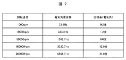
- FIG. 7 shows the relationship between the rotation speed and the phase difference when the motor is a 4-pole PMSM and the detection interval of the AD converter is 10 ⁇ s.
- the electrical angular frequency of the voltage command corresponding to the rotation speed, that is, the electrical angular frequency of the inverter output voltage is shown.
- the phase difference becomes 10 electrical degrees or more at 100,000 revolutions or more. This phase difference impairs the simultaneity of detection timing of the two-phase motor currents. Therefore, at 100,000 revolutions or more, the detection accuracy of the motor current decreases.
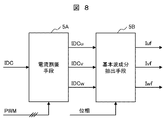
- FIG. 8 is a functional block diagram showing the configuration of the DC bus motor current detector 5 (FIG. 1) in the first embodiment.
- the DC bus motor current detector 5 inputs the voltage across the terminals of the shunt resistor as the DC bus current detection value IDC, and converts the IDC into a three-phase current detector based on the PWM control signal.
- a fundamental wave component extractor 5B is provided.
- the current allocator 5A performs current allocation according to the conventional technology described above. That is, the current divider 5A uses two-phase motor currents detected by the IDC detection values at timings before and after the timing at which the intermediate layer PWM control signal changes, and a phase current calculator ( IDC so that the remaining one-phase motor current calculated by "52" in FIG. Allocate
- the allocated three-phase motor phase currents correspond to the three-phase motor currents detected by the conventional technology described above.
- the fundamental wave component extractor 5B extracts the fundamental wave components Iuf, Ivf and Iwf from the motor phase currents IDCu, IDCv and IDCw, respectively, using a simple Fourier transform and a sine wave transfer function.
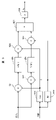
- FIG. 9 is a functional block diagram showing the configuration of the fundamental wave component extractor 5B (FIG. 8) to which the simple Fourier transform is applied.
- FIG. 9 shows only the configuration for extracting Iuf from IDCu for the U phase, but the V phase and W phase also have the same configuration.
- the fundamental wave component extractor 5B includes a cosine wave generator 5B9 that generates a cosine wave (Cos) and a sine wave generator 5B9 that generates a sine wave (Sin) according to the rotation phase of the motor.
- a generator 5B10 a multiplier 5B1 that multiplies the input signal (IDCu) by Cos and a multiplier 5B2 that multiplies Sin, a filter 5B3 that averages the output values of the multiplier 5B1, and a filter that averages the output values of the multiplier 5B2.
- a multiplier 5B5 that multiplies the output value of the filter 5B3 by Cos
- a multiplier 5B6 that multiplies the output value of the filter 5B4 by Sin
- an adder 5B7 that adds the output value of the multiplier 5B5 and the output value of the multiplier 5B6.
- an arithmetic unit 5B8 for doubling the output value of the adder 5B7 and outputting it as Iuf.
- the fundamental wave component synchronized with the rotation phase of the motor can be extracted from the motor phase current detected from the DC bus current.
- the control unit (vector controller 1, synchronous PWM converter 2) of the motor drive device of the first embodiment stably operates the motor during high-speed rotation. can be controlled as much as possible.
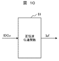
- FIG. 10 is a functional block diagram showing the configuration of the fundamental wave component extractor 5B (FIG. 8) to which the sinusoidal transfer function is applied.
- FIG. 10 for the sake of convenience, only the configuration for extracting Iuf from IDCu is shown for the U phase, but the V phase and W phase also have the same configuration.
- Equation (2) An example of a sine wave transfer function is shown in Equations (2) and (3).
- K 1 , K 2 and K 3 are control gain constants.
- Equation (3) K 4 and K 5 are control gain constants.
- the fundamental wave component of the motor phase current detected from the DC bus current can be extracted.
- the control device section of the motor driving device of the first embodiment can control the motor so that it can be operated stably during high-speed rotation.
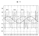
- FIG. 11 shows the motor phase currents IDCu, IDCv, and IDCw (see FIG. 8) detected by the DC bus current IDC, and the fundamental wave components Iu, Iv, and Iw of the motor current extracted from IDCu, IDCv, and IDCw (respectively, FIG. 9 is a waveform diagram showing Iuf, Ivf, and Iwf in FIG. 8).
- FIG. 12 is a waveform diagram showing the waveform of the motor current of the motor 4 rotationally driven in the first embodiment and the waveform of the DC bus current (after allocation to each phase by the current divider 5A (FIG. 8)). is. Waveforms are shown for cases where the motor rotation speed is 86000 rpm and 150000 rpm.
- Figures 11 and 12 are the results of the inventor's study through simulation.
- the rotation speed specification of the motor is 90000 rpm. Therefore, in the case of 150000 rpm, the waveform is such that the fundamental wave component can be recognized due to the effect of the so-called field-weakening control (Id* ⁇ 0).
- the fundamental wave component of the motor phase current can be extracted according to the first embodiment, and by controlling the motor based on the extracted fundamental wave component, 1 Stable high-speed rotation is possible up to pulse drive (see FIG. 2).
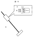
- Fig. 13 is an external view showing a schematic configuration of a stick-type vacuum cleaner.
- the vacuum cleaner 70 includes a blower section 71 having a motor and a fan rotated by the motor.
- a motor in the air blower 71 is driven by the motor driving device according to the first embodiment. Therefore, the motor can be stably rotated at high speed, and the output of the cleaner can be increased.
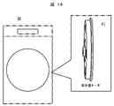
- FIG. 14 is an external view showing a schematic configuration of a drum-type washing machine.
- the washing tub of the washing machine 80 is rotated by a super multipolar motor 81.
- a super-multipole motor 81 is driven by the motor driving device according to the first embodiment.
- a multipolar motor such as the super multipolar motor 81 does not rotate at high speed as described above, but the electrical angle frequency of the inverter output voltage is high. For this reason, fluctuations in the DC bus current increase as in the case of high-speed rotation. Therefore, by being driven by the motor drive device according to the first embodiment, the rotation of the super-multipole motor 81 can be stably controlled. Therefore, by applying a super-multipolar motor to the washing machine, it is possible to reduce the vibration of the washing machine.
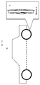
- FIG. 15 is an external view showing a schematic configuration of an electric vehicle.
- the electric vehicle 90 has a super-multipolar motor 91 as an in-wheel motor that drives the wheels.
- a super-multipole motor 91 is driven by the motor driving device according to the first embodiment. Therefore, as with the washing machine 80 (FIG. 14) described above, it is possible to reduce the vibration of the electric vehicle.
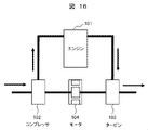
- FIG. 16 is a configuration diagram showing a schematic configuration of a hybrid turbocharger.
- a turbine 103 rotated by exhaust gas from an engine 101 and a compressor 102 driven by the turbine 103 are connected via a motor 104.
- a motor 104 is driven by the motor driving device according to the first embodiment. Therefore, the turbocharger can be assisted by the high-speed rotating motor, thereby improving the responsiveness of the turbocharger.
- the motor drive device is not limited to the above equipment, and can be applied to equipment such as machine tools, medical cutting instruments such as dental equipment, air compressors, etc., in which the motor is driven at high speed or high electrical angular frequency. can be applied to equipment such as machine tools, medical cutting instruments such as dental equipment, air compressors, etc., in which the motor is driven at high speed or high electrical angular frequency. can be applied to equipment such as machine tools, medical cutting instruments such as dental equipment, air compressors, etc., in which the motor is driven at high speed or high electrical angular frequency. can be applied to equipment such as machine tools, medical cutting instruments such as dental equipment, air compressors, etc., in which the motor is driven at high speed or high electrical angular frequency. can be applied to equipment such as machine tools, medical cutting instruments such as dental equipment, air compressors, etc., in which the motor is driven at high speed or high electrical angular frequency. can be applied to equipment such as machine tools, medical cutting instruments such as dental equipment, air compressors, etc., in which the motor is driven
- asynchronous PWM control may be applied to the PWM converter.
- the electrical angular frequency is high even if it is rotated at a low speed. Therefore, in the case where the number of PWM pulses in one cycle of the electrical angular frequency can be reduced, the fundamental wave component can be reduced according to the first embodiment. It can be extracted and the motor can be controlled stably.
- the fundamental wave component of the motor phase current detected from the DC bus current is extracted, and the motor is controlled based on this fundamental wave component, thereby increasing the inverter output voltage. Even if the electrical angular frequency is high, the motor can be controlled stably. This makes it possible to reduce the number of PWM pulses in one cycle of the electrical angle frequency to operate the motor at high speed, such as synchronous PWM control, or to operate the motor at low speed by increasing the electrical angle frequency, such as a multipolar motor. , the rotation of the motor can be stably controlled. This makes it possible to improve the performance and functionality of the equipment driven by the motor.
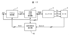
- FIG. 17 is a functional block diagram showing the configuration of a motor drive device that is Embodiment 2 of the present invention.
- phase currents flowing in the motor are detected by phase current sensors.
- the phase current sensor for example, a CT (Current Transformer) provided at the three-phase output section of the inverter 3 or the three-phase input section of the motor 4 is applied.
- the phase current of each of the three phases may be detected by a phase current sensor, or two of the three phases may be detected by a phase current sensor and the remaining one phase may be calculated.
- the detected values Iuvw_m of the three-phase motor phase currents of the motor 4 are input to the fundamental wave component extractor 5C.
- the fundamental wave component extractor 5C extracts the fundamental wave component of each phase current in the same manner as the fundamental wave component extractor 5B (FIG. 8) in the first embodiment described above.
- the fundamental wave component extractor 5C outputs the extracted fundamental wave component of the three-phase motor current to the vector controller 1 as a three-phase motor current detection value Iuvw.
- the fundamental wave component extractor 5C has a simple Fourier transform (FIG. 9) and a sine wave transfer function (FIG. 10, equations (2) and (3) ) is used to extract the fundamental wave component (Iuvw) from the detected value Iuvw_m of the motor phase current.
- the inverter by extracting the fundamental wave component of the motor phase current detected by the phase current sensor and controlling the motor based on this fundamental wave component, the inverter output Even if the electrical angular frequency of the voltage is high, the motor can be controlled stably. As a result, the rotation of the motor can be stably controlled when the motor is operated at a high speed or when a multipolar motor is operated, as in the first embodiment. and high functionality.
- FIG. 18 is a functional block diagram showing the configuration of a motor drive device that is Embodiment 3 of the present invention.
- the motor driving device of the third embodiment includes a fundamental wave component extractor 5C as in the second embodiment, and further includes a switch 6 for switching the detected value of the motor current to be supplied to the vector controller 1.
- the switch 6 In response to the speed command ⁇ *, the switch 6 outputs the detected value Iuvw_m of the motor phase current detected by the phase current sensor as in the second embodiment and the fundamental wave of Iuvw_m extracted by the fundamental wave component extractor 5C. component is selected and given to the vector controller 1 as the phase motor current detection value Iuvw.
- the switch 6 switches the fundamental wave component of Iuvw_m during high-speed rotation with a high electrical angle frequency based on the detected value Iuvw_m of the phase current of the motor detected by the phase current sensor during low-to-middle speed rotation with a low electrical angle frequency.
- Vector control is executed based on
- the motor can be stably controlled over a wide range of speeds from extremely low speeds to super high speeds.
- the present invention is not limited to the above-described embodiments, and includes various modifications.
- the above-described embodiments have been described in detail in order to explain the present invention in an easy-to-understand manner, and are not necessarily limited to those having all the described configurations.
- 1 vector controller 2 synchronous PWM converter, 3 inverter, 4 motor, 5 DC bus motor current detector, 5A current divider, 5B fundamental wave component extractor, 5C fundamental wave component extractor, 6 switch, 51 three Phase/dq converter, 52 Phase current calculator, 70 Vacuum cleaner, 71 Air blower, 80 Washing machine, 81 Super multi-pole motor, 90 Electric vehicle, 101 Engine, 102 Compressor, 103 Turbine, 104 Motor
Landscapes
- Engineering & Computer Science (AREA)
- Power Engineering (AREA)
- Transportation (AREA)
- Mechanical Engineering (AREA)
- Control Of Ac Motors In General (AREA)
Priority Applications (2)
| Application Number | Priority Date | Filing Date | Title |
|---|---|---|---|
| US18/274,153 US20250030371A1 (en) | 2021-02-17 | 2021-12-28 | Motor Control Apparatus, Motor Drive Apparatus, and Device Using Same |
| CN202180091726.9A CN116746053A (zh) | 2021-02-17 | 2021-12-28 | 电动机控制装置、电动机驱动装置以及使用该电动机驱动装置的设备 |
Applications Claiming Priority (2)
| Application Number | Priority Date | Filing Date | Title |
|---|---|---|---|
| JP2021023440A JP7586727B2 (ja) | 2021-02-17 | 2021-02-17 | モータ制御装置、モータ駆動装置並びにこれを用いた機器 |
| JP2021-023440 | 2021-02-17 |
Publications (1)
| Publication Number | Publication Date |
|---|---|
| WO2022176407A1 true WO2022176407A1 (ja) | 2022-08-25 |
Family
ID=82930721
Family Applications (1)
| Application Number | Title | Priority Date | Filing Date |
|---|---|---|---|
| PCT/JP2021/048765 Ceased WO2022176407A1 (ja) | 2021-02-17 | 2021-12-28 | モータ制御装置、モータ駆動装置並びにこれを用いた機器 |
Country Status (4)
| Country | Link |
|---|---|
| US (1) | US20250030371A1 (enExample) |
| JP (1) | JP7586727B2 (enExample) |
| CN (1) | CN116746053A (enExample) |
| WO (1) | WO2022176407A1 (enExample) |
Citations (2)
| Publication number | Priority date | Publication date | Assignee | Title |
|---|---|---|---|---|
| JP2007259675A (ja) * | 2006-03-27 | 2007-10-04 | Hitachi Appliances Inc | 電力変換器システム |
| WO2019008676A1 (ja) * | 2017-07-04 | 2019-01-10 | 三菱電機株式会社 | インバータ装置、及び、電動パワーステアリング装置 |
Family Cites Families (3)
| Publication number | Priority date | Publication date | Assignee | Title |
|---|---|---|---|---|
| JPH03155392A (ja) * | 1989-11-10 | 1991-07-03 | Toshiba Corp | 電流検出装置 |
| JP5526975B2 (ja) * | 2009-05-13 | 2014-06-18 | 株式会社安川電機 | 電動機の制御装置及びその制御方法 |
| JP5481286B2 (ja) * | 2010-06-30 | 2014-04-23 | 日立オートモティブシステムズ株式会社 | 電力変換システムおよび電力変換装置 |
-
2021
- 2021-02-17 JP JP2021023440A patent/JP7586727B2/ja active Active
- 2021-12-28 WO PCT/JP2021/048765 patent/WO2022176407A1/ja not_active Ceased
- 2021-12-28 CN CN202180091726.9A patent/CN116746053A/zh active Pending
- 2021-12-28 US US18/274,153 patent/US20250030371A1/en not_active Abandoned
Patent Citations (2)
| Publication number | Priority date | Publication date | Assignee | Title |
|---|---|---|---|---|
| JP2007259675A (ja) * | 2006-03-27 | 2007-10-04 | Hitachi Appliances Inc | 電力変換器システム |
| WO2019008676A1 (ja) * | 2017-07-04 | 2019-01-10 | 三菱電機株式会社 | インバータ装置、及び、電動パワーステアリング装置 |
Also Published As
| Publication number | Publication date |
|---|---|
| CN116746053A (zh) | 2023-09-12 |
| US20250030371A1 (en) | 2025-01-23 |
| JP7586727B2 (ja) | 2024-11-19 |
| JP2022125702A (ja) | 2022-08-29 |
Similar Documents
| Publication | Publication Date | Title |
|---|---|---|
| CN100511966C (zh) | 交流电动机的控制装置 | |
| CN1783692B (zh) | 同步电机的速度控制装置 | |
| JP4063166B2 (ja) | 電動機の制御装置 | |
| US6781333B2 (en) | Drive control apparatus and method of alternating current motor | |
| JP5853097B2 (ja) | 三相同期電動機駆動装置、一体型三相同期電動機、位置決め装置およびポンプ装置 | |
| JP3722048B2 (ja) | モーター制御装置 | |
| KR20030010480A (ko) | 전동기제어장치 | |
| CN107078675A (zh) | 逆变器控制装置以及电机驱动系统 | |
| RU2470453C1 (ru) | Устройство управления для электрической вращающейся машины | |
| EP3570432A1 (en) | Motor control device | |
| JP2002223600A (ja) | モータ制御装置 | |
| KR101251238B1 (ko) | 모터 제어 시스템 | |
| JP7154987B2 (ja) | 永久磁石同期電動機の制御装置,マイクロコンピュータ,電動機システム及び永久磁石同期電動機の運転方法 | |
| JP6293401B2 (ja) | 空気調和機のモータ制御装置及び空気調和機 | |
| JP2019115194A (ja) | 電力変換器制御装置 | |
| CN110247610A (zh) | 电动机控制装置 | |
| JP3939481B2 (ja) | 交流モータの制御装置 | |
| JP4007309B2 (ja) | モータ制御装置及びモータ制御方法 | |
| JP7586727B2 (ja) | モータ制御装置、モータ駆動装置並びにこれを用いた機器 | |
| JP2017205017A (ja) | 空気調和機のモータ制御装置及び空気調和機 | |
| JP6422796B2 (ja) | 同期機制御装置及び駆動システム | |
| JPH1198899A (ja) | Acモータ駆動装置 | |
| JP3788346B2 (ja) | 電圧形pwmインバータの制御装置 | |
| JP2009022085A (ja) | モータ制御装置とその制御方法 | |
| JP2022092879A (ja) | 交流モータ制御装置、および、それを用いた掃除機 |
Legal Events
| Date | Code | Title | Description |
|---|---|---|---|
| 121 | Ep: the epo has been informed by wipo that ep was designated in this application |
Ref document number: 21926830 Country of ref document: EP Kind code of ref document: A1 |
|
| WWE | Wipo information: entry into national phase |
Ref document number: 202180091726.9 Country of ref document: CN |
|
| WWE | Wipo information: entry into national phase |
Ref document number: 18274153 Country of ref document: US |
|
| NENP | Non-entry into the national phase |
Ref country code: DE |
|
| 122 | Ep: pct application non-entry in european phase |
Ref document number: 21926830 Country of ref document: EP Kind code of ref document: A1 |