WO2022176407A1 - モータ制御装置、モータ駆動装置並びにこれを用いた機器 - Google Patents
モータ制御装置、モータ駆動装置並びにこれを用いた機器 Download PDFInfo
- Publication number
- WO2022176407A1 WO2022176407A1 PCT/JP2021/048765 JP2021048765W WO2022176407A1 WO 2022176407 A1 WO2022176407 A1 WO 2022176407A1 JP 2021048765 W JP2021048765 W JP 2021048765W WO 2022176407 A1 WO2022176407 A1 WO 2022176407A1
- Authority
- WO
- WIPO (PCT)
- Prior art keywords
- motor
- current
- fundamental wave
- wave component
- control device
- Prior art date
Links
- 238000001514 detection method Methods 0.000 claims abstract description 44
- 239000000284 extract Substances 0.000 claims abstract description 6
- 238000000605 extraction Methods 0.000 claims abstract 3
- 230000001360 synchronised effect Effects 0.000 claims description 17
- 238000010586 diagram Methods 0.000 description 30
- 239000004065 semiconductor Substances 0.000 description 13
- 238000005406 washing Methods 0.000 description 9
- 238000005516 engineering process Methods 0.000 description 7
- 230000007423 decrease Effects 0.000 description 5
- 230000008859 change Effects 0.000 description 3
- 238000006243 chemical reaction Methods 0.000 description 3
- 238000012935 Averaging Methods 0.000 description 2
- 230000004913 activation Effects 0.000 description 2
- 230000005405 multipole Effects 0.000 description 2
- 230000003247 decreasing effect Effects 0.000 description 1
- 230000000694 effects Effects 0.000 description 1
- 238000000034 method Methods 0.000 description 1
- 238000012986 modification Methods 0.000 description 1
- 230000004048 modification Effects 0.000 description 1
- 230000004044 response Effects 0.000 description 1
- 230000004043 responsiveness Effects 0.000 description 1
- 238000004088 simulation Methods 0.000 description 1
- 238000004804 winding Methods 0.000 description 1
Images


Classifications
-
- H—ELECTRICITY
- H02—GENERATION; CONVERSION OR DISTRIBUTION OF ELECTRIC POWER
- H02P—CONTROL OR REGULATION OF ELECTRIC MOTORS, ELECTRIC GENERATORS OR DYNAMO-ELECTRIC CONVERTERS; CONTROLLING TRANSFORMERS, REACTORS OR CHOKE COILS
- H02P27/00—Arrangements or methods for the control of AC motors characterised by the kind of supply voltage
- H02P27/04—Arrangements or methods for the control of AC motors characterised by the kind of supply voltage using variable-frequency supply voltage, e.g. inverter or converter supply voltage
- H02P27/06—Arrangements or methods for the control of AC motors characterised by the kind of supply voltage using variable-frequency supply voltage, e.g. inverter or converter supply voltage using dc to ac converters or inverters
- H02P27/08—Arrangements or methods for the control of AC motors characterised by the kind of supply voltage using variable-frequency supply voltage, e.g. inverter or converter supply voltage using dc to ac converters or inverters with pulse width modulation
Definitions
- the present invention relates to a motor control device that controls an AC motor, a motor drive device that drives an AC motor at variable speeds, and equipment using the same.
- Synchronous PWM control (see, for example, Patent Document 1) is used to change the PWM carrier frequency and the number of pulses for each electrical angle frequency for high-speed rotation control of the motor.
- a DC bus current detection method (see Patent Documents 2 and 3, for example) that detects a three-phase AC current without using a phase current sensor is used to detect the motor current.
- the PWM carrier frequency changes in synchronization with the electrical angle rotation frequency, and the number of PWM pulses is controlled to be a multiple of 3 (odd number) and 1 pulse. In other words, during high-speed rotation, the number of PWM pulses decreases to a maximum of 1 pulse.
- the DC bus current detection method is a method of reproducing the fundamental wave component of the motor current by distributing the DC bus current detected almost simultaneously according to the combination of PWM pulses to each phase.
- the simultaneity of detection of the DC bus current changes depending on the detection capability of the AD converter of the microcomputer (hereinafter referred to as a microcomputer). In other words, when the motor rotates at high speed, the simultaneity of the DC bus current cannot be ensured, and the reproduction error of the motor current increases.
- the present invention provides a motor control device, a motor drive device, and the like, which can detect the fundamental wave component of the motor current with high accuracy even when the electrical angular frequency is high as in high-speed driving, and can stably control the motor.
- a motor control device a motor drive device, and the like, which can detect the fundamental wave component of the motor current with high accuracy even when the electrical angular frequency is high as in high-speed driving, and can stably control the motor.
- a motor control device generates a control signal for controlling a motor based on a speed command and a detected value of motor current. and a fundamental wave component extracting means for extracting a fundamental wave component of the phase current of the motor detected by the phase current detecting means, wherein the fundamental wave component extracted by the fundamental wave component extracting means is A control signal is created as a detected value of the motor current.
- a motor drive device includes an inverter that drives and controls a motor, and a control section that generates a control signal for controlling the inverter.
- 1 is a motor control device according to the invention
- the equipment according to the present invention is driven by a motor, and the motor is driven by the motor driving device according to the present invention.
- the motor current fundamental wave component can be detected with high accuracy even when the electrical angle frequency is high.
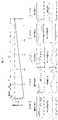
- FIG. 1 is a functional block diagram showing the configuration of a motor drive device that is Embodiment 1.
- FIG. 3 is a waveform diagram showing waveforms of a line voltage and a motor phase current output by an inverter 3;
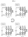
- FIG. 3 is a circuit diagram showing currents flowing through a main circuit portion of the inverter 3;
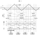
- FIG. 4 is a waveform diagram showing operation waveforms of the motor driving device (inverter 3 and control device section);
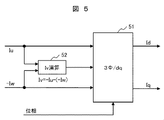
- FIG. 4 is a functional block diagram showing an example of a motor current computing unit that computes a motor current from a detected value of a DC bus current;
- FIG. 3 is a waveform diagram showing waveforms of a line voltage and a motor phase current output by an inverter 3
- FIG. 3 is a circuit diagram showing currents flowing through a main circuit portion of the inverter 3
- FIG. 4 is a waveform diagram showing operation waveforms of the motor driving device (inverter 3 and control device section)
- FIG. 4 is
- FIG. 4 is a waveform diagram showing operation waveforms of the motor driving device when the motor rotates at high speed; The relationship between the rotation speed and the phase difference is shown when the motor is a 4-pole PMSM and the detection interval of the AD converter is 10 ⁇ s.
- 4 is a functional block diagram showing the configuration of a DC bus motor current detector 5 in Embodiment 1.
- FIG. 3 is a functional block diagram showing the configuration of a fundamental wave component extractor 5B to which simple Fourier transform is applied;
- FIG. 2 is a functional block diagram showing the configuration of a fundamental wave component extractor 5B to which a sine wave transfer function is applied;
- FIG. 4 is a waveform diagram showing a motor phase current detected by a DC bus current and a fundamental wave component of the motor current extracted from the motor phase current; 4 is a waveform diagram showing a waveform of a motor current and a waveform of a DC bus current of a motor 4 rotationally driven in Embodiment 1.
- FIG. 1 is an external view showing a schematic configuration of a stick-type vacuum cleaner;
- FIG. 1 is an external view showing a schematic configuration of a drum-type washing machine;
- FIG. 1 is an external view showing a schematic configuration of an electric vehicle;
- FIG. 1 is a configuration diagram showing a schematic configuration of a hybrid turbocharger;
- FIG. 5 is a functional block diagram showing the configuration of a motor drive device that is Embodiment 2;
- FIG. 11 is a functional block diagram showing the configuration of a motor drive device that is Embodiment 3;
- Example 1 will be described using FIGS.
- FIG. 1 is a functional block diagram showing the configuration of a motor drive device that is Embodiment 1 of the present invention.
- the motor driving device of the first embodiment includes an inverter 3 that applies three-phase AC voltages Vu, Vv, and Vw to the motor 4 .
- a permanent magnet synchronous motor (hereinafter referred to as “PMSM”) is applied as the motor 4 in the first embodiment.
- the inverter 3 has an inverter circuit such as a three-phase bridge circuit composed of power semiconductor switching elements (eg, IGBTs and power MOSFETs).
- the inverter circuit converts the input DC voltage from the DC power supply into a three-phase AC voltage by turning on and off the semiconductor switching elements, and outputs this three-phase AC voltage to the motor 4 .
- the control unit for controlling the on/off of the semiconductor switching elements that make up the inverter circuit includes a synchronous PWM converter 2 that creates a pulse width modulation (hereinafter referred to as "PWM") control signal, speed commands ⁇ * and three A vector controller 1 that creates a three-phase voltage command Vuvw based on the phase motor current Iuvw and gives Vuvw to a synchronous PWM converter 2, and a DC bus current IDC in the inverter 3 is detected, and Iuvw is detected from the detected value of IDC. and a DC bus motor current detector 5 that reproduces
- PWM pulse width modulation
- the vector controller 1 employs simple vector control (see Patent Document 4) that does not use a current controller.
- Iq: T is the time constant).
- the d-axis current command Id * which is the current command for the d-axis component in the rotating coordinate system of the motor current, is set to zero.
- the vector controller 1 calculates the d-axis voltage command Vd * and the q-axis voltage command Vd* and the q-axis voltage command using the voltage equation represented by the formula (1) based on the rotation speed command ⁇ r * and the above Iq * and Id * . Compute Vq * .
- R, Lq, Ld, and Ke are the winding resistance, q-axis inductance, d-axis inductance, and induced voltage constant, respectively.
- the vector controller 1 creates a three-phase voltage command Vuvw from Vd * and Vq * by dq/three-phase conversion.
- the period of the carrier wave signal and the period of the sinusoidal command signal (modulated wave signal) are in an integral multiple relationship, and so-called synchronous PWM control is applied to synchronize the phases of both signals (Patent Reference 1).
- Synchronous PWM control generally changes the carrier frequency according to changes in the output frequency of the inverter.
- the number of pulses in one cycle of the PWM control signal is often constant regardless of the inverter output frequency, but the number of pulses may be switched according to the inverter output frequency.
- the number of PWM pulses and the carrier frequency are set for each electrical angular frequency and set to Vuvw.
- a PWM control signal (upper arm) is created according to the carrier frequency.
- the inverter 3 is a DC/AC converter made up of semiconductor switching elements, and generates a three-phase AC voltage (Vu, Vv, Vw) are output as PWM pulses.
- the motor 4 is driven by this PWM pulse.
- the PWM control signal may be given to the semiconductor switching element via the driver circuit.
- the inverter 3 also has a shunt resistor that detects the DC bus current.
- the voltage across the terminals of the shunt resistor is input to the DC bus motor current detector 5 as the DC bus current detection value IDC.
- the DC bus motor current detector 5 extracts the fundamental wave component Iuvw of the motor current based on the detected value IDC of the DC bus current and the PWM control signal (upper arm), and outputs the extracted Iuvw to the vector controller 1. do.
- FIG. 2 is a waveform diagram showing waveforms of the line voltage and the motor phase current output by the inverter 3.
- FIG. 2 is a waveform diagram showing waveforms of the line voltage and the motor phase current output by the inverter 3.
- the rotation speed of the motor 4 is accelerated from 0 rpm to 100,000 rpm.
- the vector controller 1 creates a PWM control signal by asynchronous PWM control at low speeds, but after switching to synchronous PWM control, as the rotation speed increases, the pulse of the PWM control signal per half cycle of the voltage command increases. The number is decreased stepwise from 15 pulses to 1 pulse.
- FIG. 3 is a circuit diagram showing the current flowing through the main circuit section of the inverter 3.
- the motor current can be detected by detecting the DC bus current flowing through the shunt resistor.
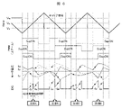
- FIG. 4 is a waveform diagram showing operation waveforms of the motor drive device (inverter 3 and control device section).
- each waveform of the carrier wave signal and the three-phase voltage command Vuvw (modulated wave signal), the waveform of the PWM control signal (upper arm) created based on the carrier signal and the three-phase voltage command Vuvw,
- the waveforms of the three-phase motor currents Iu, Iv, and Iw and the waveform of the DC bus current IDC are shown.
- the points shown in the waveforms of the motor currents Iu and Iw and the DC bus current IDC indicate the timing at which the DC bus motor current detector 5 in the control unit of the inverter 3 detects the DC bus current.
- This detection timing corresponds to, for example, the activation timing of the A/D conversion function provided in the microcomputer that constitutes the control device section.
- the detection timing of the DC bus current is the timing before and after the timing at which the intermediate-phase PWM control signal (pulse) in the three-phase applied voltage command Vuvw (modulation wave signal) changes.
- FIG. 4 shows the timing before and after the timing at which the V-phase PWM control signal changes.
- the DC bus motor current detector 5 detects two-phase motor currents, although the detection timings are different.
- the IDC detects two-phase motor currents (-Iw, Iu) at timings before and after phase A, and based on -Iw and Iu, three-phase motor currents with phase A as a reference. (Iu, Iv, Iw) is calculated. Furthermore, the IDC detects two-phase motor currents (Iu, -Iw) at timings before and after phase B, and based on Iu, -Iw, three-phase motor currents (Iu, Iv, Iw) is calculated.
- the operation modes of the inverter 3 before and after the phase A correspond to Mode 2 (SupON, SvpON, SwnON (SwpOFF)) and Mode 3 (SupON, SvnON (SvpOFF), SwnON (SwpOFF)) in FIG. there is
- the three-phase motor current is detected by repeating detection of the IDC at timings before and after the timing at which the PWM control signal changes, and connecting the detected values.
- the motor speed is medium to low (the number of pulses>3: see FIG. 2), the fundamental wave component of the motor current is detected.
- FIG. 5 is a functional block diagram showing an example of a motor current calculator that calculates the motor current from the detected value of the DC bus current. It should be noted that although this computing unit is based on conventional technology, it is also partially applied to the first embodiment.
- phase current calculator is also applied to the first embodiment.
- FIG. 5 also shows a three-phase/dq converter 51 included in the vector controller 1 .
- the three-phase motor current detection value by the IDC is directly input to the three-phase/dq converter 51 .
- the first embodiment will be described later.
- FIG. 6 is a waveform diagram showing operation waveforms of the motor drive device when the motor rotates at high speed (rotation speed at which the number of pulses is 3 in FIG. 2).
- FIG. 4 is a waveform diagram showing waveforms of (upper arm), three-phase motor currents Iu, Iv, and Iw, and DC bus current IDC;
- the waveforms of the motor currents Iu and Iw and the DC bus current IDC in FIG. shows the timing of detecting the bus current.
- This detection timing corresponds to, for example, the activation timing of the A/D conversion function provided in the microcomputer that constitutes the control device section.
- the IDC detects the two-phase motor current even during high-speed rotation.
- the combination of the phases of the detected motor currents (for example, V phase and U phase in phase A) are all different in phases A, B, and C.
- the detection interval of the AD converter is shortened in order to bring the detection timings of the two-phase motor currents closer together to improve the simultaneity of detection, the peak and bottom values of the motor current of each phase will be detected. It is difficult to detect the fundamental wave component of the motor current.
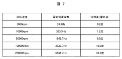
- FIG. 7 shows the relationship between the rotation speed and the phase difference when the motor is a 4-pole PMSM and the detection interval of the AD converter is 10 ⁇ s.
- the electrical angular frequency of the voltage command corresponding to the rotation speed, that is, the electrical angular frequency of the inverter output voltage is shown.
- the phase difference becomes 10 electrical degrees or more at 100,000 revolutions or more. This phase difference impairs the simultaneity of detection timing of the two-phase motor currents. Therefore, at 100,000 revolutions or more, the detection accuracy of the motor current decreases.
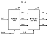
- FIG. 8 is a functional block diagram showing the configuration of the DC bus motor current detector 5 (FIG. 1) in the first embodiment.
- the DC bus motor current detector 5 inputs the voltage across the terminals of the shunt resistor as the DC bus current detection value IDC, and converts the IDC into a three-phase current detector based on the PWM control signal.
- a fundamental wave component extractor 5B is provided.
- the current allocator 5A performs current allocation according to the conventional technology described above. That is, the current divider 5A uses two-phase motor currents detected by the IDC detection values at timings before and after the timing at which the intermediate layer PWM control signal changes, and a phase current calculator ( IDC so that the remaining one-phase motor current calculated by "52" in FIG. Allocate
- the allocated three-phase motor phase currents correspond to the three-phase motor currents detected by the conventional technology described above.
- the fundamental wave component extractor 5B extracts the fundamental wave components Iuf, Ivf and Iwf from the motor phase currents IDCu, IDCv and IDCw, respectively, using a simple Fourier transform and a sine wave transfer function.
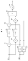
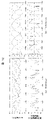
- FIG. 9 is a functional block diagram showing the configuration of the fundamental wave component extractor 5B (FIG. 8) to which the simple Fourier transform is applied.
- FIG. 9 shows only the configuration for extracting Iuf from IDCu for the U phase, but the V phase and W phase also have the same configuration.
- the fundamental wave component extractor 5B includes a cosine wave generator 5B9 that generates a cosine wave (Cos) and a sine wave generator 5B9 that generates a sine wave (Sin) according to the rotation phase of the motor.
- a generator 5B10 a multiplier 5B1 that multiplies the input signal (IDCu) by Cos and a multiplier 5B2 that multiplies Sin, a filter 5B3 that averages the output values of the multiplier 5B1, and a filter that averages the output values of the multiplier 5B2.
- a multiplier 5B5 that multiplies the output value of the filter 5B3 by Cos
- a multiplier 5B6 that multiplies the output value of the filter 5B4 by Sin
- an adder 5B7 that adds the output value of the multiplier 5B5 and the output value of the multiplier 5B6.
- an arithmetic unit 5B8 for doubling the output value of the adder 5B7 and outputting it as Iuf.
- the fundamental wave component synchronized with the rotation phase of the motor can be extracted from the motor phase current detected from the DC bus current.
- the control unit (vector controller 1, synchronous PWM converter 2) of the motor drive device of the first embodiment stably operates the motor during high-speed rotation. can be controlled as much as possible.
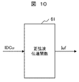
- FIG. 10 is a functional block diagram showing the configuration of the fundamental wave component extractor 5B (FIG. 8) to which the sinusoidal transfer function is applied.
- FIG. 10 for the sake of convenience, only the configuration for extracting Iuf from IDCu is shown for the U phase, but the V phase and W phase also have the same configuration.
- Equation (2) An example of a sine wave transfer function is shown in Equations (2) and (3).
- K 1 , K 2 and K 3 are control gain constants.
- Equation (3) K 4 and K 5 are control gain constants.
- the fundamental wave component of the motor phase current detected from the DC bus current can be extracted.
- the control device section of the motor driving device of the first embodiment can control the motor so that it can be operated stably during high-speed rotation.
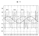
- FIG. 11 shows the motor phase currents IDCu, IDCv, and IDCw (see FIG. 8) detected by the DC bus current IDC, and the fundamental wave components Iu, Iv, and Iw of the motor current extracted from IDCu, IDCv, and IDCw (respectively, FIG. 9 is a waveform diagram showing Iuf, Ivf, and Iwf in FIG. 8).
- FIG. 12 is a waveform diagram showing the waveform of the motor current of the motor 4 rotationally driven in the first embodiment and the waveform of the DC bus current (after allocation to each phase by the current divider 5A (FIG. 8)). is. Waveforms are shown for cases where the motor rotation speed is 86000 rpm and 150000 rpm.
- Figures 11 and 12 are the results of the inventor's study through simulation.
- the rotation speed specification of the motor is 90000 rpm. Therefore, in the case of 150000 rpm, the waveform is such that the fundamental wave component can be recognized due to the effect of the so-called field-weakening control (Id* ⁇ 0).
- the fundamental wave component of the motor phase current can be extracted according to the first embodiment, and by controlling the motor based on the extracted fundamental wave component, 1 Stable high-speed rotation is possible up to pulse drive (see FIG. 2).
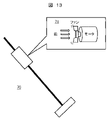
- Fig. 13 is an external view showing a schematic configuration of a stick-type vacuum cleaner.
- the vacuum cleaner 70 includes a blower section 71 having a motor and a fan rotated by the motor.
- a motor in the air blower 71 is driven by the motor driving device according to the first embodiment. Therefore, the motor can be stably rotated at high speed, and the output of the cleaner can be increased.
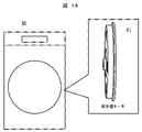
- FIG. 14 is an external view showing a schematic configuration of a drum-type washing machine.
- the washing tub of the washing machine 80 is rotated by a super multipolar motor 81.
- a super-multipole motor 81 is driven by the motor driving device according to the first embodiment.
- a multipolar motor such as the super multipolar motor 81 does not rotate at high speed as described above, but the electrical angle frequency of the inverter output voltage is high. For this reason, fluctuations in the DC bus current increase as in the case of high-speed rotation. Therefore, by being driven by the motor drive device according to the first embodiment, the rotation of the super-multipole motor 81 can be stably controlled. Therefore, by applying a super-multipolar motor to the washing machine, it is possible to reduce the vibration of the washing machine.
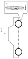
- FIG. 15 is an external view showing a schematic configuration of an electric vehicle.
- the electric vehicle 90 has a super-multipolar motor 91 as an in-wheel motor that drives the wheels.
- a super-multipole motor 91 is driven by the motor driving device according to the first embodiment. Therefore, as with the washing machine 80 (FIG. 14) described above, it is possible to reduce the vibration of the electric vehicle.
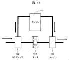
- FIG. 16 is a configuration diagram showing a schematic configuration of a hybrid turbocharger.
- a turbine 103 rotated by exhaust gas from an engine 101 and a compressor 102 driven by the turbine 103 are connected via a motor 104.
- a motor 104 is driven by the motor driving device according to the first embodiment. Therefore, the turbocharger can be assisted by the high-speed rotating motor, thereby improving the responsiveness of the turbocharger.
- the motor drive device is not limited to the above equipment, and can be applied to equipment such as machine tools, medical cutting instruments such as dental equipment, air compressors, etc., in which the motor is driven at high speed or high electrical angular frequency. can be applied to equipment such as machine tools, medical cutting instruments such as dental equipment, air compressors, etc., in which the motor is driven at high speed or high electrical angular frequency. can be applied to equipment such as machine tools, medical cutting instruments such as dental equipment, air compressors, etc., in which the motor is driven at high speed or high electrical angular frequency. can be applied to equipment such as machine tools, medical cutting instruments such as dental equipment, air compressors, etc., in which the motor is driven at high speed or high electrical angular frequency. can be applied to equipment such as machine tools, medical cutting instruments such as dental equipment, air compressors, etc., in which the motor is driven at high speed or high electrical angular frequency. can be applied to equipment such as machine tools, medical cutting instruments such as dental equipment, air compressors, etc., in which the motor is driven
- asynchronous PWM control may be applied to the PWM converter.
- the electrical angular frequency is high even if it is rotated at a low speed. Therefore, in the case where the number of PWM pulses in one cycle of the electrical angular frequency can be reduced, the fundamental wave component can be reduced according to the first embodiment. It can be extracted and the motor can be controlled stably.
- the fundamental wave component of the motor phase current detected from the DC bus current is extracted, and the motor is controlled based on this fundamental wave component, thereby increasing the inverter output voltage. Even if the electrical angular frequency is high, the motor can be controlled stably. This makes it possible to reduce the number of PWM pulses in one cycle of the electrical angle frequency to operate the motor at high speed, such as synchronous PWM control, or to operate the motor at low speed by increasing the electrical angle frequency, such as a multipolar motor. , the rotation of the motor can be stably controlled. This makes it possible to improve the performance and functionality of the equipment driven by the motor.
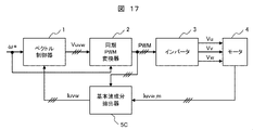
- FIG. 17 is a functional block diagram showing the configuration of a motor drive device that is Embodiment 2 of the present invention.
- phase currents flowing in the motor are detected by phase current sensors.
- the phase current sensor for example, a CT (Current Transformer) provided at the three-phase output section of the inverter 3 or the three-phase input section of the motor 4 is applied.
- the phase current of each of the three phases may be detected by a phase current sensor, or two of the three phases may be detected by a phase current sensor and the remaining one phase may be calculated.
- the detected values Iuvw_m of the three-phase motor phase currents of the motor 4 are input to the fundamental wave component extractor 5C.
- the fundamental wave component extractor 5C extracts the fundamental wave component of each phase current in the same manner as the fundamental wave component extractor 5B (FIG. 8) in the first embodiment described above.
- the fundamental wave component extractor 5C outputs the extracted fundamental wave component of the three-phase motor current to the vector controller 1 as a three-phase motor current detection value Iuvw.
- the fundamental wave component extractor 5C has a simple Fourier transform (FIG. 9) and a sine wave transfer function (FIG. 10, equations (2) and (3) ) is used to extract the fundamental wave component (Iuvw) from the detected value Iuvw_m of the motor phase current.
- the inverter by extracting the fundamental wave component of the motor phase current detected by the phase current sensor and controlling the motor based on this fundamental wave component, the inverter output Even if the electrical angular frequency of the voltage is high, the motor can be controlled stably. As a result, the rotation of the motor can be stably controlled when the motor is operated at a high speed or when a multipolar motor is operated, as in the first embodiment. and high functionality.
- FIG. 18 is a functional block diagram showing the configuration of a motor drive device that is Embodiment 3 of the present invention.
- the motor driving device of the third embodiment includes a fundamental wave component extractor 5C as in the second embodiment, and further includes a switch 6 for switching the detected value of the motor current to be supplied to the vector controller 1.
- the switch 6 In response to the speed command ⁇ *, the switch 6 outputs the detected value Iuvw_m of the motor phase current detected by the phase current sensor as in the second embodiment and the fundamental wave of Iuvw_m extracted by the fundamental wave component extractor 5C. component is selected and given to the vector controller 1 as the phase motor current detection value Iuvw.
- the switch 6 switches the fundamental wave component of Iuvw_m during high-speed rotation with a high electrical angle frequency based on the detected value Iuvw_m of the phase current of the motor detected by the phase current sensor during low-to-middle speed rotation with a low electrical angle frequency.
- Vector control is executed based on
- the motor can be stably controlled over a wide range of speeds from extremely low speeds to super high speeds.
- the present invention is not limited to the above-described embodiments, and includes various modifications.
- the above-described embodiments have been described in detail in order to explain the present invention in an easy-to-understand manner, and are not necessarily limited to those having all the described configurations.
- 1 vector controller 2 synchronous PWM converter, 3 inverter, 4 motor, 5 DC bus motor current detector, 5A current divider, 5B fundamental wave component extractor, 5C fundamental wave component extractor, 6 switch, 51 three Phase/dq converter, 52 Phase current calculator, 70 Vacuum cleaner, 71 Air blower, 80 Washing machine, 81 Super multi-pole motor, 90 Electric vehicle, 101 Engine, 102 Compressor, 103 Turbine, 104 Motor
Landscapes
- Engineering & Computer Science (AREA)
- Power Engineering (AREA)
- Control Of Ac Motors In General (AREA)
Abstract
電気角周波数が高い場合でも、モータ電流基本波成分を高精度に検出して、安定にモータを駆動制御できるモータ制御装置、モータ駆動装置並びにこれを用いた機器が開示される。このモータ制御装置は、速度指令(ω*)とモータ電流の検出値(Iuvw)とに基づいて、モータ(4)を制御するための制御信号(PWM)を作成するものであって、モータの相電流を検出する相電流検出手段と、相電流検出手段によって検出されるモータの相電流の基本波成分を抽出する基本波成分抽出手段(5)と、を備え、基本波成分手段によって抽出される基本波成分をモータ電流の検出値として、制御信号を作成する。
Description
本発明は、交流モータを制御するモータ制御装置、交流モータを可変速駆動するモータ駆動装置並びにこれを用いた機器に関する。
一般産業、家電、自動車等の様々な分野において、小型高出力化を目的にモータの更なる高速回転化が進んでいる。
モータの高速回転制御のために、PWMキャリア周波数とパルス数を電気角周波数毎に変更する同期PWM制御(例えば、特許文献1参照)が用いられる。
また、モータ電流の検出には、相電流センサを用いずに三相交流電流を検出する直流母線電流検出法(例えば、特許文献2,3参照)が用いられる。
また、永久磁石同期モータの高速回転制御には、電流制御器が省略された簡易ベクトル制御(例えば、特許文献4参照)が用いられる。
特許文献1で記載されている同期PWM制御は、電気角回転周波数に同期してPWMキャリア周波数が変化し、PWMパルス数が3の倍数(奇数)及び1パルスになるように制御される。言い換えると、高速回転時はPWMパルス数が減少し、最大1パルスになる。
PWMパルス数が減少するとモータ電流の変動幅が増加し、後述する直流母線電流検出法での電流検出が困難になる。
また、直流母線電流検出法は、PWMパルスの組合せに応じてほぼ同時に検出した直流母線電流を各相に振り分けてモータ電流の基本波成分を再現する方式であるが、制御器であるマイクロコンピュータ(以下、マイコンと称す)のAD変換器の検出能力に依存し、直流母線電流の検出の同時性が変化する。言い換えると、高速回転時には直流母線電流の同時性が担保できなくなりモータ電流の再現誤差が増加していく。
そこで、本発明は、高速駆動時のように電気角周波数が高い場合でも、モータ電流基本波成分を高精度に検出して、安定にモータを駆動制御できるモータ制御装置、モータ駆動装置並びにこれを用いた機器を提供する。
上記課題を解決するために、本発明によるモータ制御装置は、速度指令とモータ電流の検出値とに基づいて、モータを制御するための制御信号を作成するものであって、モータの相電流を検出する相電流検出手段と、相電流検出手段によって検出されるモータの相電流の基本波成分を抽出する基本波成分抽出手段と、を備え、基本波成分抽出手段によって抽出される基本波成分をモータ電流の検出値として、制御信号を作成する。
上記課題を解決するために、本発明によるモータ駆動装置は、モータを駆動制御するインバータと、インバータを制御する制御信号を作成する制御部と、を備えるものであって、制御部は、上記本発明によるモータ制御装置である。
上記課題を解決するために、本発明による機器は、モータによって駆動されるものであって、モータが、上記本発明によるモータ駆動装置によって駆動される。
本発明によれば、電気角周波数が高い場合でも、モータ電流基本波成分を高精度に検出することができる。
以下、本発明の実施形態について、下記の実施例1~3により、図面を用いながら説明する。
各図において、参照番号が同一のものは同一の構成要件あるいは類似の機能を備えた構成要件を示している。
図1~16を用いて、実施例1について説明する。
図1は、本発明の実施例1であるモータ駆動装置の構成を示す機能ブロック図である。
図1に示すように、本実施例1のモータ駆動装置は、モータ4に三相交流電圧Vu,Vv,Vwを印加するインバータ3を備えている。なお、本実施例1では、モータ4として、永久磁石同期モータ(以下、「PMSM」と記す)が適用される。
インバータ3は、電力用の半導体スイッチング素子(例えば、IGBTやパワーMOSFET)によって構成される三相ブリッジ回路のようなインバータ回路を有する。インバータ回路は、半導体スイッチング素子をオン・オフすることにより、直流電源からの入力直流電圧を三相交流電圧に変換して、この三相交流電圧をモータ4へ出力する。
インバータ回路を構成する半導体スイッチング素子のオン・オフを制御する制御装置部は、パルス幅変調(以下、「PWM」と記す)制御信号を作成する同期PWM変換器2と、速度指令ω*および三相モータ電流Iuvwに基づいて三相電圧指令Vuvwを作成して、Vuvwを同期PWM変換器2に与えるベクトル制御器1と、インバータ3における直流母線電流IDCを検出して、IDCの検出値からIuvwを再現する直流母線モータ電流検出器5とから構成される。
ベクトル制御器1では、電流制御器を用いない簡易的ベクトル制御(特許文献4参照)が適用される。簡易的ベクトル制御においては、モータ電流の回転座標系におけるq軸成分であるq軸電流Iqの一次遅れフィルタ値をq軸電流指令Iq*とする(Iq*=(1/(1+T・s))Iq:Tは時定数)。なお、モータ電流の回転座標系におけるd軸成分の電流指令であるd軸電流指令Id*は零とする。
ベクトル制御器1は、回転速度指令ωr
*と、上述のIq*およびId*に基づいて、式(1)で表される電圧方程式を用いて、d軸電圧指令Vd*およびq軸電圧指令Vq*を演算する。

式(1)において、R,Lq,Ld,Keは、それぞれ、巻線抵抗、q軸インダクタンス、d軸インダクタンス、誘起電圧定数である。
ベクトル制御器1は、Vd*およびVq*から、dq/三相変換により、三相電圧指令Vuvwを作成する。
したがって、本実施例1では、モータ電流の基本波成分を検出すれば、電流フィードバック制御系なしで、ベクトル制御が可能である。
同期PWM変換器2では、キャリア波信号の周期と正弦波指令信号(変調波信号)の周期が整数倍の関係にあり、両信号の位相を同期させる、いわゆる同期PWM制御が適用される(特許文献1参照)。
同期PWM制御においては、一般的に、インバータの出力周波数の変化に応じて、キャリア周波数を変化させる。また、同期PWM制御においては、多くの場合、インバータ出力周波数によらずPWM制御信号の一周期のパルス数が一定であるが、インバータ出力周波数に応じてパルス数を切り換える場合もある。本実施例1における同期PWM変換器2においては、三相電圧指令Vuvwと回転速度指令ωr
*とに基づいて、電気角周波数ごとにPWMパルス数およびキャリア周波数が設定され、Vuvwと設定されたキャリア周波数に応じてPWM制御信号(上アーム)が作成される。
インバータ3は、上述のように、半導体スイッチング素子で構成された直流/交流変換器であり、同期PWM変換器2が出力するPWM制御信号(上アーム)に基づいて、三相交流電圧(Vu,Vv,Vw)をPWMパルスで出力する。このPWMパルスによって、モータ4が駆動される。なお、PWM制御信号は、ドライバ回路を介して、半導体スイッチング素子に与えられてもよい。
また、インバータ3は、直流母線電流を検出するシャント抵抗を備えている。シャント抵抗の端子間電圧は、直流母線電流の検出値IDCとして、直流母線モータ電流検出器5に入力される。
直流母線モータ電流検出器5は、直流母線電流の検出値IDCとPWM制御信号(上アーム)とに基づいて、モータ電流の基本波成分Iuvwを抽出し、抽出したIuvwをベクトル制御器1に出力する。
以下、直流母線モータ電流検出器5の動作および直流母線モータ電流検出器5の構成について説明する。
まず、直流母線モータ電流検出器5の動作の内、従来の直流母線電流検出法(特許文献2,3参照)と共通する動作について、図2~7を用いて説明する。
図2は、インバータ3が出力する線間電圧およびモータ相電流の各波形を示す波形図である。
なお、図2の上図に示すように、モータ4の回転速度は、0rpmから10万rpmまで加速されている。ベクトル制御器1は、低速時には非同期PWM制御にてPWM制御信号を作成するが、同期PWM制御に切り換えた後は、回転速度が高くなるにしたがって、電圧指令の半周期あたりのPWM制御信号のパルス数を15パルスから1パルスまで、段階的に減少させる。
図2に示すように、モータ4の回転速度が高くなるにしたがって、線間電圧のPWMパルス数は減少し、6万rpmを超えると、電気角半周期あたり1パルスとなる。このとき、PWMパルス数が減少するためモータ相電流はリップルが大きくなり、PWMパルス数が3パルス以下では、モータ電流の波形からは基本波成分の大きさが不明確になる。このため、従来の直流母線電流検出法だけでは、モータ4の高速回転時に、モータ電流の基本波成分を所望の精度で検出することが難しく、モータ4の制御が不安定となる恐れがある。よって、このようなモータ電流からモータ電流の基本波成分を検出する電流検出方式が望まれている。
図3は、インバータ3の主回路部に流れる電流を示す回路図である。
半導体スイッチング素子(図3ではIGBT)の各動作モード(Mode1~4)において、電流の流れる回路部を太線で示す。
Mode1のように、上アームの半導体スイッチング素子Sup,Svp,Swpが全てONの場合、並びに、Mode4のように、下アームの半導体スイッチング素子Sun,Svn,Swnが全てONの場合、モータ電流は、シャント抵抗には流れない(IDC=0)。
また、Mode2のように、上アームの半導体スイッチング素子Sup,Svpと下アームの半導体スイッチング素子SwnがONの場合、並びに、Mode3のように、上アームの半導体スイッチング素子Supと下アームの半導体スイッチング素子Svn,SwnがONの場合、モータ電流が、シャント抵抗に流れる(IDC=-Iw(Mode2),IDC=Iu(Mode3))。
したがって、シャント抵抗にモータ電流が流れる動作モードで、シャント抵抗に流れる直流母線電流を検出することにより、モータ電流を検出することができる。
ここで、図4を用いて、直流母線電流検出値IDCからモータ電流を検出する手段について説明する。
図4は、モータ駆動装置(インバータ3および制御装置部)の動作波形を示す波形図である。
図4中、上から順に、キャリア波信号および三相電圧指令Vuvw(変調波信号)の各波形、キャリア信号および三相電圧指令Vuvwに基づいて作成されるPWM制御信号(上アーム)の波形、三相のモータ電流Iu,Iv,Iwの波形、直流母線電流IDCの波形である。
図4中、モータ電流Iu,Iwおよび直流母線電流IDCの各波形中に記載されている点は、インバータ3の制御装置部における直流母線モータ電流検出器5が直流母線電流を検出するタイミングを示す。この検出タイミングは、例えば、制御装置部を構成するマイクロコンピュータが備えるA/D変換機能の起動タイミングに相当する。
直流母線電流の検出タイミングは、三相印加電圧指令Vuvw(変調波信号)の内の中間相のPWM制御信号(パルス)が変化するタイミングの前後のタイミングである。図4では、V相のPWM制御信号の変化するタイミングの前後のタイミングである。
中間相のPWM制御パルスが変化する前後のタイミングにおいては、前述の図3におけるMode2,3のように、上アームおよび下アームの一方および他方において、それぞれ、三相の内の一相の半導体スイッチング素子および他の二相の半導体スイッチング素子がONである。したがって、各タイミングにおいては、三相の内の異なる一相のモータ電流が検出される。すなわち、直流母線モータ電流検出器5は、検出するタイミングは異なるものの、2相のモータ電流を検出する。
図4に示すように、IDCによって位相Aの前後のタイミングで2相のモータ電流(-Iw,Iu)が検出され、-Iw,Iuに基づいて、位相Aを基準にして3相のモータ電流(Iu,Iv,Iw)が算出される。さらに、IDCによって位相Bの前後のタイミングで2相のモータ電流(Iu,-Iw)が検出され、Iu,-Iwに基づいて、位相Bを基準にして3相のモータ電流(Iu,Iv,Iw)が算出される。
なお、位相Aの前後のタイミングにおけるインバータ3の動作モードは、それぞれ図2におけるMode2(SupON,SvpON,SwnON(SwpOFF))、Mode3(SupON,SvnON(SvpOFF),SwnON(SwpOFF))に対応している。
このようなPWM制御信号が変化するタイミングの前後のタイミングにおけるIDCの検出を繰り返して、検出値を繋ぎ合わせることにより、三相モータ電流が検出される。そして、モータ速度が中低速(パルス数>3:図2参照)の場合には、モータ電流の基本波成分が検出される。
なお、上述のように三相のモータ電流の内の二相がIDCによって検出され、残りの1相は、次に説明するように、検出された2相から演算される。
図5は、直流母線電流の検出値からモータ電流を演算するモータ電流演算器の一例を示す機能ブロック図である。なお、本演算器は、従来技術によるものであるが、一部、本実施例1においても適用される。
モータ電流演算器は、IDCによって検出される2相(図5ではU相およびW相)のモータ電流から、「Iu+Iv+Iw=0」という関係を用いて残りの1相(図5ではV相)が相電流演算器(図5ではV相電流(Iv)演算器52)によって演算される。
このような相電流演算器は、本実施例1においても適用される。
なお、図5においては、ベクトル制御器1が備える三相/dq変換器51も示される。従来技術では、IDCによる三相モータ電流検出値が直接、三相/dq変換器51に入力される。本実施例1については、後述する。
ここで、モータの高速回転時のようにモータ電流の変動成分が大きいと、直流母線電流の検出値も大きく変動する。このため、従来技術(特許文献2参照)では、直流母線電流の検出タイミングによってはモータ電流の変動成分が検出され、モータ電流の検出精度が低くなる。
また、従来技術として、PWM制御信号を操作することで、キャリア波信号の連続する2期間(周期)における直流母線電流の検出値を平均化することにより、モータ電流の変動成分をキャンセルする技術もある(特許文献3参照)。しかし、期間Aと期間Bとで、電気角位相の変化が小さければ検出値の平均化が有効であるが、変化が大きくなると本技術でもモータ電流の変動成分のキャンセルは難しい。
したがって、従来技術では、モータの高速回転時のように、キャリア周波数1周期の間に電気角位相が大きく変化する場合、モータ電流の基本波成分を精度よく検出することが難しい。
図4では、モータの回転速度が中低速であるため、三相電圧指令Vuvw(変調波信号)の変化が緩やかであり、直流母線電流の流れる期間にVuvw検出の大きさがほぼ一定値である場合には、2相のモータ電流を異なるタイミングで検出しても、同じタンミングで検出した場合との誤差は小さい。これに対し、次に図6を用いて説明するように、モータの高速回転時は、誤差が大きくなる。
図6は、モータの高速回転時(図2におけるパルス数が3となる回転速度)における、モータ駆動装置の動作波形を示す波形図である。
図4と同様に、図6中、上から順に、キャリア波信号および三相電圧指令Vuvw(変調波信号)の各波形、キャリア波信号および三相電圧指令Vuvwに基づいて作成されるPWM制御信号(上アーム)の波形、三相のモータ電流Iu,Iv,Iwおよび直流母線電流IDCの各波形を示す波形図である。
また、図4と同様に、図6中、モータ電流Iu,Iwおよび直流母線電流IDCの各波形中に記載されている点は、インバータ3の制御装置部における直流母線モータ電流検出器5が直流母線電流を検出するタイミングを示す。この検出タイミングは、例えば、制御装置部を構成するマイクロコンピュータが備えるA/D変換機能の起動タイミングに相当する。
図6に示すように、高速回転時においても、IDCによって、2相のモータ電流が検出される。ただし、検出されるモータ電流の相の組み合わせ(例えば、位相AではV相とU相)は、位相A,B,Cにおいてすべて異なる。また、2相のモータ電流の検出タイミングを近づけて検出の同時性を向上するために、AD変換器の検出間隔を短くすると、各相のモータ電流のピーク値やボトム値が検出されるので、モータ電流の基本波成分を検出することが難しい。
また、図6に示すように、各相の前後でIDCが流れる各期間の中心付近でモータ電流が検出されるようにAD変換器の検出間隔を設定すると、2相のモータ電流の検出タイミングの同時性が損なわれる。このため、モータ電流の検出精度が低下し、モータ制御の安定性が低下する。特に、本実施例1のように、電流制御器を有さずモータ電流検出値から電流指令を演算する簡易的ベクトル制御では、モータの高速回転制御が困難になる。
ここで、本発明者の検討による、モータ回転速度と、IDCによる2相のモータ電流の電流検出タイミングの位相差との関係について説明する。
図7は、モータを4極のPMSMとし、AD変換器の検出間隔を10μsとする場合における、回転速度と位相差の関係を示す。なお、回転速度に対応する電圧指令の電気角周波数、すなわちインバータ出力電圧の電気角周波数を示す。
図7に示すように、10万回転以上では位相差が電気角で10度以上となる。この位相差では、2相のモータ電流の検出タイミングの同時性が損なわれる。したがって、10万回転以上ではモータ電流の検出精度が低下する。
上述のように、直流母線電流によってモータ電流を検出する従来技術では、モータの回転速度が高速になると、モータ電流の基本波成分を検出することが困難になり、モータの安定した制御が難しくなる。
これに対し、本実施例1によれば、以下に説明するように、高速回転時においても、直流母線電流によるモータ電流の検出が可能になる。
図8は、本実施例1における直流母線モータ電流検出器5(図1)の構成を示す機能ブロック図である。
図8に示すように、直流母線モータ電流検出器5(図1)は、シャント抵抗の端子間電圧を直流母線電流検出値IDCとして入力し、IDCを、PWM制御信号に基づいて、三相のモータ相電流(IDCu,IDCv,IDCw)に割り振る電流割振器5Aと、割り振られた三相のモータ相電流(IDCu,IDCv,IDCw)の各々から基本波成分(Iuf,Ivf,Iwf)を抽出する基本波成分抽出器5Bを備える。
電流割振器5Aは、上述の従来技術により、電流の割り振りを実行する。すなわち、電流割振器5Aは、中間層のPWM制御信号が変化するタイミングの前後のタイミングのIDCの検出値によって検出される二相のモータ電流と、これら二相のモータ電流から相電流演算器(図5における「52」)によって演算される残りの一相のモータ電流とを、三相のモータ相電流(IDCu,IDCv,IDCw)の内の対応する相のモータ相電流とするように、IDCを割り振る。
したがって、割り振られた三相のモータ相電流(IDCu,IDCv,IDCw)は、上述の従来技術によって検出される三相のモータ電流に相当する。
基本波成分抽出器5Bは、簡易フーリエ変換や正弦波伝達関数を用いて、モータ相電流IDCu,IDCv,IDCwから、それぞれ、基本波成分Iuf,Ivf,Iwfを抽出する。
図9は、簡易フーリエ変換が適用される基本波成分抽出器5B(図8)の構成を示す機能ブロック図である。なお、図9では、便宜上、U相について、IDCuからIufを抽出するための構成のみを示すが、V相およびW相についても同様の構成である。
図9に示すように、基本波成分抽出器5B(図8)は、モータの回転位相に応じて余弦波(Cos)を発生する余弦波発生器5B9および正弦波(Sin)を発生する正弦波発生器5B10、入力信号(IDCu)にCosを乗算する乗算器5B1およびSinを乗算する乗算器5B2、乗算器5B1の出力値を平均化するフィルタ5B3および乗算器5B2の出力値を平均化するフィルタ5B4、フィルタ5B3の出力値にCosを乗算する乗算器5B5およびフィルタ5B4の出力値にSinを乗算する乗算器5B6、乗算器5B5の出力値と乗算器5B6の出力値とを加算する加算器5B7、加算器5B7の出力値を2倍してIufとして出力する演算器5B8を備えている。
図9に示す基本波成分抽出器によれば、直流母線電流から検出されるモータ相電流の、モータの回転位相に同期した基本波成分を抽出することができる。この基本波成分をモータ電流検出値とすることにより、本実施例1のモータ駆動装置の制御装置部(ベクトル制御器1、同期PWM変換器2)は、高速回転時において、モータを安定に運転できるように制御することができる。
図10は、正弦波伝達関数が適用される基本波成分抽出器5B(図8)の構成を示す機能ブロック図である。なお、図10では、便宜上、U相について、IDCuからIufを抽出するための構成のみを示すが、V相およびW相についても同様の構成である。
正弦波伝達関数の一例を式(2)および式(3)に示す。

式(2)において、K1,K2,K3は制御ゲイン定数である。

式(3)において、K4,K5は制御ゲイン定数である。
式(2)および(3)に示す正弦波伝達関数は、角周波数ω0でゲインが最大となるゲイン特性を有する。したがって、ω0をモータの回転電気角周波数に設定することにより、モータ電流の基本波成分を抽出することができる。なお、このようなゲイン特性を有する伝達関数であれば、他の関数形でもよい。
図10に示す基本波成分抽出器によれば、図9に示す基本波成分抽出器と同様に、直流母線電流から検出されるモータ相電流の基本波成分を抽出することができる。この基本波成分をモータ電流検出値とすることにより、本実施例1のモータ駆動装置の制御装置部は、高速回転時において、モータを安定に運転できるように制御することができる。
図11は、直流母線電流IDCによって検出されるモータ相電流IDCu,IDCv,IDCw(図8参照)と、IDCu,IDCv,IDCwから抽出されたモータ電流の基本波成分Iu,Iv,Iw(それぞれ、図8のIuf,Ivf,Iwfに対応)を示す波形図である。
また、図12は、本実施例1において回転駆動されているモータ4のモータ電流の波形と直流母線電流(電流割振器5A(図8)による各相への割振り後)の波形を示す波形図である。なお、モータ回転数が86000rpmおよび150000rpmの場合について、波形を示す。
図11および図12は、シミュレーションによる本発明者の検討結果である。本検討においては、モータの回転速度仕様を90000rpmとしている。このため、150000rpmの場合では、いわゆる弱め界磁制御(Id*≠0)の効果により、基本波成分がわかるような波形になっている。
上記のような本発明者の検討によれば、本実施例1により、モータ相電流の基本波成分を抽出することができ、抽出された基本波成分に基づいてモータを制御することにより、1パルス駆動(図2参照)まで、安定した高速回転が可能になる。
次に、本実施例1のモータ駆動装置を用いた機器として、掃除機、洗濯機、電動車、ハイブリッドチャージャーについて説明する。
図13は、スティック型の掃除機の概略的な構成を示す外観図である。
掃除機70は、モータおよびモータによって回転されるファンを有する送風部71を備えている。送風部71におけるモータが、本実施例1によるモータ駆動装置によって駆動される。したがって、モータを安定に高速回転させることができるので、掃除機の出力を増加することができる。
図14は、ドラム型の洗濯機の概略的な構成を示す外観図である。
洗濯機80の洗濯槽は、超多極モータ81によって回転される。超多極モータ81が、本実施例1によるモータ駆動装置によって駆動される。超多極モータ81のような多極モータは、前述のような高速回転をさせることはないが、インバータ出力電圧の電気角周波数は高い。このため、高速回転時と同様に、直流母線電流の変動が大きくなる。したがって、本実施例1によるモータ駆動装置によって駆動することにより、超多極モータ81を安定に回転制御することができる。このため、洗濯機に超多極モータを適用して、洗濯機を低振動化することができる。
図15は、電動車の概略的な構成を示す外観図である。
電動車90は、車輪を駆動するインホイールモータとして超多極モータ91を備えている。超多極モータ91が、本実施例1によるモータ駆動装置によって駆動される。したがって、上述の洗濯機80(図14)と同様に、電動車の低振動化が可能になる。
図16は、ハイブリッドターボチャージャーの概略的な構成を示す構成図である。
図16に示すように、エンジン101の排気によって回転するタービン103と、タービン103によって駆動されるコンプレッサ102とが、モータ104を介して接続される。モータ104が本実施例1によるモータ駆動装置によって駆動される。したがって、高速回転仕様のモータによりアシストすることができるので、ターボチャージャーの応答性が向上する。
なお、本実施例1によるモータ駆動装置は、上述の機器に限らず、工作機械、歯科用などの医療用切削器具、空気圧縮機など、モータが高速度もしくは高電気角周波数で駆動される機器に適用できる。
また、PWM変換器には、非同期PWM制御が適用されてもよい。たとえば、多極モータのように、低速で回転させても電気角周波数は高いため、電気角周波数の一周期におけるPWMパルス数が少なくなり得る場合には、本実施例1により、基本波成分を抽出して、モータを安定に制御できる。
上述のように、本実施例1によれば、直流母線電流から検出されるモータ相電流の基本波成分を抽出して、この基本波成分に基づいてモータを制御することにより、インバータ出力電圧の電気角周波数が高くても、安定にモータを制御できる。これにより、同期PWM制御のように、電気角周波数の一周期におけるPWMパルス数を少なくしてモータを高速運転する場合や、多極モータのように電気角周波数を高くして低速運転する場合に、モータの回転を安定に制御することができる。これにより、モータによって駆動される機器の高性能化や高機能化が可能になる。
図17は、本発明の実施例2であるモータ駆動装置の構成を示す機能ブロック図である。
以下、主に、実施例1と異なる点について説明する。
本実施例2においては、モータに流れる相電流が相電流センサによって検出される。相電流センサとしては、例えば、インバータ3の三相出力部もしくはモータ4の三相入力部に設けられるCT(Current Transformer)が適用される。なお、三相の各相電流を相電流センサにより検出してもよいし、三相の内の二相を相電流センサにより検出し、残りの1相を演算してもよい。
図2に示すように、モータ4の三相のモータ相電流の検出値Iuvw_mは、基本波成分抽出器5Cに入力される。基本波成分抽出器5Cは、前述の実施例1における基本波成分抽出器5B(図8)と同様に、各相電流の基本波成分を抽出する。基本波成分抽出器5Cは、抽出した三相のモータ電流の基本波成分を、三相モータ電流検出値Iuvwとしてベクトル制御器1に出力する。
基本波成分抽出器5Cは、実施例1における基本波成分抽出器5B(図8)と同様に、簡易フーリエ変換(図9)や正弦波伝達関数(図10、式(2)および(3))を用いて、モータ相電流の検出値Iuvw_mから、基本波成分(Iuvw)を抽出する。
本実施例2によれば、相電流センサにより検出されるモータ相電流の基本波成分を抽出して、この基本波成分に基づいてモータを制御することにより、実施例1と同様に、インバータ出力電圧の電気角周波数が高くても、安定にモータを制御できる。これにより、実施例1と同様に、モータを高速運転する場合や、多極モータを運転する場合に、モータの回転を安定に制御することができるので、モータによって駆動される機器の高性能化や高機能化が可能になる。
図18は、本発明の実施例3であるモータ駆動装置の構成を示す機能ブロック図である。
以下、主に、実施例2と異なる点について説明する。
本実施例3のモータ駆動装置は、実施例2と同様に、基本波成分抽出器5Cを備えるとともに、さらに、ベクトル制御器1に与えるモータ電流の検出値を切り替える切替器6を備える。
切替器6は、速度指令ω*に応じて、実施例2と同様に相電流センサによって検出されるモータの相電流の検出値Iuvw_mと、基本波成分抽出器5Cによって抽出されるIuvw_mの基本波成分とのいずれか一方を選択して、相モータ電流検出値Iuvwとしてベクトル制御器1に与える。
切替器6により、電気角周波数が低い低中速回転時は、相電流センサによって検出されるモータの相電流の検出値Iuvw_mに基づき、電気角周波数が高い高速回転時は、Iuvw_mの基本波成分に基づいて、ベクトル制御が実行される。
本実施例3によれば、極低速時から超高速時までの広い速度範囲で、モータを安定に制御できる。
なお、本発明は前述した実施形態に限定されるものではなく、様々な変形例が含まれる。例えば、前述した実施例は本発明を分かりやすく説明するために詳細に説明したものであり、必ずしも説明した全ての構成を備えるものに限定されるものではない。また、各実施例の構成の一部について、他の構成の追加・削除・置き換えをすることが可能である。
1 ベクトル制御器、2 同期PWM変換器、3 インバータ、4 モータ、5 直流母線モータ電流検出器、5A 電流割振器、5B 基本波成分抽出器、5C 基本波成分抽出器、6 切替器、51 三相/dq変換器、52 相電流演算器、70 掃除機、71 送風部、80 洗濯機、81 超多極モータ、90 電動車、101 エンジン、102 コンプレッサ、103 タービン、104 モータ
Claims (13)
- 速度指令とモータ電流の検出値とに基づいて、モータを制御するための制御信号を作成するモータ制御装置において、
前記モータの相電流を検出する相電流検出手段と、
前記相電流検出手段によって検出される前記モータの前記相電流の基本波成分を抽出する基本波成分抽出手段と、
を備え、
前記基本波成分抽出手段によって抽出される前記基本波成分を前記モータ電流の前記検出値として、前記制御信号を作成することを特徴とするモータ制御装置。 - 請求項1に記載のモータ制御装置において、
前記相電流検出手段は、前記モータを駆動するインバータにおける直流母線電流の検出値から前記相電流を検出することを特徴とするモータ制御装置。 - 請求項1に記載のモータ制御装置において、
前記相電流検出手段は、相電流センサであることを特徴とするモータ制御装置。 - 請求項3に記載のモータ制御装置において、
前記速度指令に応じて、前記相電流センサによって検出される前記相電流と、前記基本波成分との一方を選択する切替器を備え、
前記切替器によって選択される前記相電流または前記基本波成分を前記モータ電流の前記検出値として、前記制御信号を作成することを特徴とするモータ制御装置。 - 請求項1に記載のモータ制御装置において、
前記基本波成分抽出手段は、簡易フーリエ変換により、前記基本波成分を抽出することを特徴とするモータ制御装置。 - 請求項1に記載のモータ制御装置において、
前記基本波成分抽出手段は、正弦波伝達関数により、前記基本波成分を抽出することを特徴とするモータ制御装置。 - 請求項1に記載のモータ制御装置において、
前記制御信号がPWM信号であり、
変調波信号となる電圧指令とキャリア波とに基づいて、前記PWM信号を作成するPWM変換器と、
前記速度指令と前記モータ電流の前記検出値とに基づいて、前記電圧指令を作成する制御器と、
を備えることを特徴とするモータ制御装置。 - 請求項7に記載のモータ制御装置において、
前記PWM変換器は、同期PWMによって前記PWM信号を作成することを特徴とするモータ制御装置。 - 請求項7に記載のモータ制御装置において、
前記制御器は、前記モータの電圧方程式に基づき、前記モータ電流から演算される電流指令に応じて前記電圧指令を作成することを特徴とするモータ制御装置。 - 請求項9に記載のモータ制御装置において、
前記制御器は、簡易ベクトル制御により、前記電圧指令を作成することを特徴とするモータ制御装置。 - 請求項1に記載のモータ制御装置において、
前記モータが多極モータであることを特徴とするモータ制御装置。 - モータを駆動制御するインバータと、
前記インバータを制御する制御信号を作成する制御部と、
を備えるモータ駆動装置において、
前記制御部は、
速度指令とモータ電流の検出値とに基づいて前記制御信号を作成し、
前記モータの相電流を検出する相電流検出手段と、
前記相電流検出手段によって検出される前記モータの前記相電流の基本波成分を抽出する基本波成分抽出手段と、
を備え、
前記基本波成分抽出手段によって抽出される前記基本波成分を前記モータ電流の前記検出値として、前記制御信号を作成することを特徴とするモータ駆動装置。 - モータによって駆動される機器において、
前記モータが、請求項12に記載のモータ駆動装置によって駆動されることを特徴とする機器。
Priority Applications (1)
| Application Number | Priority Date | Filing Date | Title |
|---|---|---|---|
| CN202180091726.9A CN116746053A (zh) | 2021-02-17 | 2021-12-28 | 电动机控制装置、电动机驱动装置以及使用该电动机驱动装置的设备 |
Applications Claiming Priority (2)
| Application Number | Priority Date | Filing Date | Title |
|---|---|---|---|
| JP2021023440A JP2022125702A (ja) | 2021-02-17 | 2021-02-17 | モータ制御装置、モータ駆動装置並びにこれを用いた機器 |
| JP2021-023440 | 2021-02-17 |
Publications (1)
| Publication Number | Publication Date |
|---|---|
| WO2022176407A1 true WO2022176407A1 (ja) | 2022-08-25 |
Family
ID=82930721
Family Applications (1)
| Application Number | Title | Priority Date | Filing Date |
|---|---|---|---|
| PCT/JP2021/048765 WO2022176407A1 (ja) | 2021-02-17 | 2021-12-28 | モータ制御装置、モータ駆動装置並びにこれを用いた機器 |
Country Status (3)
| Country | Link |
|---|---|
| JP (1) | JP2022125702A (ja) |
| CN (1) | CN116746053A (ja) |
| WO (1) | WO2022176407A1 (ja) |
Citations (2)
| Publication number | Priority date | Publication date | Assignee | Title |
|---|---|---|---|---|
| JP2007259675A (ja) * | 2006-03-27 | 2007-10-04 | Hitachi Appliances Inc | 電力変換器システム |
| WO2019008676A1 (ja) * | 2017-07-04 | 2019-01-10 | 三菱電機株式会社 | インバータ装置、及び、電動パワーステアリング装置 |
-
2021
- 2021-02-17 JP JP2021023440A patent/JP2022125702A/ja active Pending
- 2021-12-28 CN CN202180091726.9A patent/CN116746053A/zh active Pending
- 2021-12-28 WO PCT/JP2021/048765 patent/WO2022176407A1/ja active Application Filing
Patent Citations (2)
| Publication number | Priority date | Publication date | Assignee | Title |
|---|---|---|---|---|
| JP2007259675A (ja) * | 2006-03-27 | 2007-10-04 | Hitachi Appliances Inc | 電力変換器システム |
| WO2019008676A1 (ja) * | 2017-07-04 | 2019-01-10 | 三菱電機株式会社 | インバータ装置、及び、電動パワーステアリング装置 |
Also Published As
| Publication number | Publication date |
|---|---|
| JP2022125702A (ja) | 2022-08-29 |
| CN116746053A (zh) | 2023-09-12 |
Similar Documents
| Publication | Publication Date | Title |
|---|---|---|
| JP4063166B2 (ja) | 電動機の制御装置 | |
| JP5853097B2 (ja) | 三相同期電動機駆動装置、一体型三相同期電動機、位置決め装置およびポンプ装置 | |
| US7064514B2 (en) | Motor drive system for AC motors | |
| JP3722048B2 (ja) | モーター制御装置 | |
| KR20030010480A (ko) | 전동기제어장치 | |
| RU2470453C1 (ru) | Устройство управления для электрической вращающейся машины | |
| EP1460758A2 (en) | Vector control method and apparatus | |
| WO2018131093A1 (ja) | モータ制御装置 | |
| JP2002223600A (ja) | モータ制御装置 | |
| KR101251238B1 (ko) | 모터 제어 시스템 | |
| JP7094859B2 (ja) | モータ制御装置及びモータ制御方法 | |
| CN113381649B (zh) | 用于直流无刷电机的控制方法和控制装置 | |
| JP6293401B2 (ja) | 空気調和機のモータ制御装置及び空気調和機 | |
| JP2008118797A (ja) | モータ模擬装置、およびモータ模擬方法 | |
| JP3939481B2 (ja) | 交流モータの制御装置 | |
| WO2022176407A1 (ja) | モータ制御装置、モータ駆動装置並びにこれを用いた機器 | |
| JP4007309B2 (ja) | モータ制御装置及びモータ制御方法 | |
| JP2009273302A (ja) | 電動モータの制御装置 | |
| JP2017205017A (ja) | 空気調和機のモータ制御装置及び空気調和機 | |
| JP2002191188A (ja) | 位置センサレスモータ制御方法及び制御装置 | |
| JP7154987B2 (ja) | 永久磁石同期電動機の制御装置,マイクロコンピュータ,電動機システム及び永久磁石同期電動機の運転方法 | |
| JPH1198899A (ja) | Acモータ駆動装置 | |
| JP3788346B2 (ja) | 電圧形pwmインバータの制御装置 | |
| WO2020170324A1 (ja) | 電力変換装置および電動パワーステアリング装置 | |
| JP2009022085A (ja) | モータ制御装置とその制御方法 |
Legal Events
| Date | Code | Title | Description |
|---|---|---|---|
| 121 | Ep: the epo has been informed by wipo that ep was designated in this application |
Ref document number: 21926830 Country of ref document: EP Kind code of ref document: A1 |
|
| WWE | Wipo information: entry into national phase |
Ref document number: 202180091726.9 Country of ref document: CN |
|
| NENP | Non-entry into the national phase |
Ref country code: DE |
|
| 122 | Ep: pct application non-entry in european phase |
Ref document number: 21926830 Country of ref document: EP Kind code of ref document: A1 |