WO2022176054A1 - データ照合装置、データ照合システム、及びデータ照合方法 - Google Patents
データ照合装置、データ照合システム、及びデータ照合方法 Download PDFInfo
- Publication number
- WO2022176054A1 WO2022176054A1 PCT/JP2021/005884 JP2021005884W WO2022176054A1 WO 2022176054 A1 WO2022176054 A1 WO 2022176054A1 JP 2021005884 W JP2021005884 W JP 2021005884W WO 2022176054 A1 WO2022176054 A1 WO 2022176054A1
- Authority
- WO
- WIPO (PCT)
- Prior art keywords
- expected value
- data
- output data
- value information
- matching
- Prior art date
- Legal status (The legal status is an assumption and is not a legal conclusion. Google has not performed a legal analysis and makes no representation as to the accuracy of the status listed.)
- Ceased
Links
Images


Classifications
-
- G—PHYSICS
- G05—CONTROLLING; REGULATING
- G05B—CONTROL OR REGULATING SYSTEMS IN GENERAL; FUNCTIONAL ELEMENTS OF SUCH SYSTEMS; MONITORING OR TESTING ARRANGEMENTS FOR SUCH SYSTEMS OR ELEMENTS
- G05B19/00—Program-control systems
- G05B19/02—Program-control systems electric
- G05B19/04—Program control other than numerical control, i.e. in sequence controllers or logic controllers
- G05B19/05—Programmable logic controllers, e.g. simulating logic interconnections of signals according to ladder diagrams or function charts
-
- G—PHYSICS
- G06—COMPUTING OR CALCULATING; COUNTING
- G06F—ELECTRIC DIGITAL DATA PROCESSING
- G06F11/00—Error detection; Error correction; Monitoring
- G06F11/28—Error detection; Error correction; Monitoring by checking the correct order of processing
Definitions
- the present disclosure relates to a sequence program data collation device, a data collation system, and a data collation method.
- a programmable logic controller is a controller generally used for device control in a factory, and executes a sequence program for device control.
- PLC programmable logic controller
- sequence program After creating a sequence program, it is necessary to check whether the program works as expected.
- the sequence program is executed in a state that simulates the input data and internal memory state during operation of the device, and the output data and internal memory state obtained as a result are as intended. verify whether However, there is a problem that such verification work is troublesome.
- Control devices such as PLCs that control peripheral devices by sequence control repeatedly execute sequence programs, refresh processing for digital input/output, and communication processing with peripheral devices. Therefore, the execution cycle of the sequence program varies depending on the condition of branching conditions in the sequence program, the load condition of communication processing, and the like. For example, if there is a timer function in the sequence program, the output will turn ON after the set time has elapsed after the input contact of the timer is turned ON. Therefore, the timing at which the output of the timer is turned on also fluctuates according to the above-described fluctuations in the execution period.
- Patent Document 1 discloses a method of collating the operation of a sequence program using expected value information, which is a combination of input data and output data expected for the PLC. It does not disclose a matching method when the execution cycle fluctuates and the timing of the output data deviates.
- the present disclosure has been made to solve the above problems, and aims to be able to collate the data of the sequence program even when the execution cycle of the sequence program fluctuates.
- the data matching device includes an expected value information generation unit that generates expected value information including time data, input data, and output data corresponding to a timing chart that defines sequence control; , an execution cycle setting unit that sets the execution cycle of the sequence program, the execution cycle of the sequence program, and the virtual input data based on the input data of the expected value information, executes the processing of the sequence program, and outputs virtual output data.
- a control unit a matching interval setting unit that sets a matching interval having a time width based on the time of at least one of the output data in matching the output data of the virtual output data and the expected value information, and in the set matching interval, an expected value matching unit for matching the virtual output data and the output data of the expected value information;
- the data collating device can collate the data of the sequence program even when the execution cycle of the sequence program fluctuates.
- FIG. 1 is a block diagram showing the configuration of a PLC according to Embodiment 1;
- FIG. A diagram showing an example of a timing chart according to the first embodiment A diagram showing an example of expected value information according to Embodiment 1
- FIG. 5 is a diagram illustrating comparison between expected value information and virtual data according to Embodiment 1;
- FIG. 5 is a diagram illustrating comparison between expected value information and virtual data according to Embodiment 1;
- FIG. 5 is a diagram illustrating comparison between expected value information and virtual data according to Embodiment 1;
- FIG. 5 is a diagram illustrating comparison between expected value information and virtual data according to Embodiment 1;
- 1 is a block diagram showing the configuration of a data matching system according to Embodiment 1.
- Block diagram showing configuration of PLC according to Embodiment 2 A diagram showing an example of a timing chart according to Embodiment 2 A diagram showing an example of collation enable/disable settings according to the second embodiment
- Block diagram showing configuration of PLC according to Embodiment 3 A diagram showing an example of replacement data according to the third embodiment
- a diagram showing an example of replacement data settings according to the third embodiment Flowchart for explaining the data matching method according to the third embodiment Modified example of the hardware configuration of the control unit according to the first to third embodiments
- FIG. 1 is a block diagram showing the configuration of PLC 1 according to Embodiment 1.
- the PLC 1 includes a control section 2 , an input setting section 3 and an expected value matching section 4 .
- the PLC 1 is connected to peripheral devices such as a PC (Personal Computer), a programmable display, and a device to be controlled, and inputs and outputs data therebetween.
- peripheral devices such as a PC (Personal Computer), a programmable display, and a device to be controlled, and inputs and outputs data therebetween.
- the data collating device in the present disclosure includes a PLC, and may also include other control equipment such as a numerical controller that incorporates PLC functions and performs sequence control, a programmable display, and the like. The same applies to the following embodiments, and the functions will be described using the PLC as an example of the data matching device.
- the control unit 2 is a microcomputer and includes a processor 21, a storage unit 22, and an operation mode switching unit 23.
- the processor 21 is, for example, a CPU (Central Processing Unit), a microprocessor, or a DSP (Digital Signal Processor).
- the storage unit 22 is, for example, RAM (Random Access Memory), ROM (Read Only Memory), or HDD (Hard Disk Drive), and stores user programs including sequence programs, other software, firmware, log data, and the like. Peripheral devices connected to the PLC 1 are controlled by the processor 21 executing the sequence program stored in the storage unit 22 .
- the storage unit 22 is not limited to being included in the control unit 2, and may be a recording medium removable from the PLC 1, for example.
- the operation mode switching unit 23 switches between these two modes.
- the control unit 2 performs a sequence based on the actual input data input from the peripheral device and the information in the internal memory of the storage unit 22 (corresponding to the device described later). Execute the processing of the program. Actual output data obtained by the processing is output to the peripheral device or output to the storage unit 22 .
- the control unit 2 executes the sequence program with respect to the virtual input data based on the sequence program execution cycle and the input data of the expected value information.
- the control unit 2 outputs virtual output data obtained by executing the processing of the sequence program to the outside or stores it in the storage unit 22 .
- “Actual input data” is the data that is actually input to the PLC 1 from the peripheral device, such as when the peripheral device connected to the PLC 1 is controlled by the sequence program.
- Real output data is output data obtained by executing a sequence program on real input data.
- the virtual input data is set by the input setting unit 3 based on the execution period of the sequence program and the input data of the expected value information.
- Virtual output data is output data obtained by executing sequence program processing on virtual input data.
- the term “virtual” here is an expression added to distinguish between real input data and real output data.
- the operation mode switching unit 23 is an additional component for switching between the normal operation mode and the expected value comparison mode, and switching may be performed based on a command from a peripheral device.
- the input setting unit 3 sets input data used for matching sequence programs.
- the input setting unit 3 includes an expected value information generation unit 31 , an execution cycle setting unit 32 and a matching interval setting unit 33 .
- the expected value information generation unit 31 generates expected value information including time data, input data, and output data corresponding to a timing chart that defines sequence control.
- the execution cycle setting unit 32 sets the execution cycle of the sequence program.
- the collation interval setting unit 33 sets a collation interval having a time width based on the time of at least one of the output data when collating the virtual output data and the output data of the expected value information.
- the execution cycle setting of the execution cycle setting unit 32 may be set by the user by estimating the execution cycle and setting an arbitrary value.
- the execution cycle may be set automatically or by the user.
- the execution cycle setting unit 32 may include measuring means for measuring the execution cycle of the sequence program.
- Engineering tools for sequence program design are generally used when creating a new sequence program or modifying an existing program.
- the engineering tool is installed on a PC, and is capable of designing, editing, and simulating the operation of sequence programs.
- the user uses an engineering tool to design the actual input data and output data of the PLC 1 and the expected state of the internal memory as a timing chart, and creates a sequence program that executes control according to the timing chart.
- the created sequence program is transmitted from the PC to the PLC 1 side and stored in the storage unit 22 .
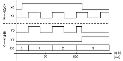
- FIG. 2 is a diagram showing an example of a timing chart.
- the timing chart defines sequence control, and represents input data and output data at each time when the sequence program is executed.
- Devices include bit devices and word devices.
- a bit device is a device that handles 1-bit information
- X is a device symbol for receiving a signal from the outside
- Y is a device symbol for outputting a signal to the outside.
- a word device is a device that handles numerical values and character strings
- D is a device symbol representing a data register that stores numerical values and character strings as device values.
- FIG. 3 is a diagram showing an example of expected value information.
- the expected value information corresponds to the timing chart of FIG. 2, and includes time data and input data and output data corresponding to the time data of each device.
- the expected value information generation unit 31 generates expected value information including time data, input data, and output data corresponding to the timing chart.
- FIG. 3 is a schematic example, and may include input data and output data corresponding to a shorter interval of time data. Information other than time data, input data, and output data may also be included.
- the expected value information generation unit 31 executes the sequence program based on the input data of the expected value information about the sequence program before change and the execution cycle of the sequence program, and outputs virtual output data and , the input data of the expected value information may be used to generate the expected value information. Even if you change the sequence program, there are many parts of the expected value information that are the same as the existing process, and even if you do not design the expected value information newly, you can use the same expected value information input data as before the change If the expected value information can be generated based on the output data obtained by executing the sequence program before change, it is possible to reduce the labor for generating the expected value information in comparing the sequence program after change.
- the expected value information generation unit 31 may execute a sequence program based on actual input data, and generate expected value information using the outputted actual output data and actual input data.
- a PLC sequence program built into the device, and in changing the sequence program, if you want to generate expected value information based on a new input data pattern, instead of designing virtual input data, By using the input data and the actual output data, it is possible to reduce the effort required to generate the expected value information.
- the expected value information generation unit 31 when expected value information is generated using actual input data and actual output data, the expected value information generation unit 31 generates expected values from the actual input data and actual output data of the sequence program before change.
- the start trigger condition if the actual input is ON or OFF (level trigger), or if the condition is a change from OFF to ON or from ON to OFF (edge trigger), the value of the device is specified. If the value is within or outside the range of a specific value, if all of the above multiple conditions are satisfied, if any condition is satisfied, a certain time before the time when the condition was satisfied ( pre-trigger) can be set.
- the end trigger in addition to the same conditions as the start trigger, the condition that a certain period of time has elapsed since the occurrence of the start trigger may be used. As a result, the expected value information to be used for collating the sequence program after the change is automatically created, and the labor for creating the expected value information can be reduced.
- the execution cycle setting unit 32 may set the execution cycle of the sequence program after change based on the measured value of the execution cycle measured in the sequence program before change.
- the matching interval setting unit 33 may set a matching interval to be used for data matching of the changed sequence program based on the measured value of the execution cycle measured in the sequence program before the change.
- FIG. 4 is a diagram illustrating a comparison of expected value information and virtual data.
- Expected value information X0 and Y1 are shown in the upper row, and virtual data X0 (virtual input data) and Y1 (virtual output data) are shown in the lower row.
- the expected value information is as described with reference to the timing chart of FIG. 2 and FIG.
- a deviation occurs between the virtual data and the expected value information due to variations in the execution cycle of the sequence program. For example, when the sequence program was created, the execution cycle was estimated to be 1.00 ms, but when it is actually executed, it may be 1.05 ms. may vary to 1.50 ms.
- the execution cycle setting unit 32 sets, as the execution cycle of the sequence program, a fixed value corresponding to variations in the execution cycle (for example, based on the average value obtained by measuring the varying execution cycles), or when executing the sequence program
- the execution cycle of the sequence program is dynamically set based on the obtained execution cycle measurement value.
- the dynamic setting when the execution cycle varies, for example, 1.20 ms or 1.50 ms, the measured value obtained when the sequence program is executed may be set, or the value calculated from the measured value. and an arbitrary fixed value may be used as the execution period.
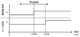
- FIG. 5 is a diagram illustrating a comparison of expected value information and virtual data, and is an enlarged excerpt from the time 110 ms of the output data of the expected value information and Y1 of the virtual output data in FIG.
- the execution cycle setting unit 32 sets the execution cycle as a fixed value of 1.00 ms, but the actual execution cycle is 1.05 ms due to fluctuations will be described as an example.
- Y1 as virtual output data is turned ON at the timing when the input X0 is turned OFF.
- the matching interval setting unit 33 sets a matching interval with a time width based on the time of the virtual output data.
- the expected value collating unit 4 collates the virtual output data with output data of expected value information included in the set interval (expected value information output data group). For example, with 110.25 ms of the virtual output data Y1 as a reference, a matching interval of 1.00 ms before and after that is set for a total of 2.00 ms (109.25 ms to 111.25 ms), and the virtual output data and the set matching interval Match with the expected value information output data group in.
- the output of the expected value information becomes OFF at time 109.50 ms, which coincides with the OFF of the virtual output data.
- a comparison interval of 1.00 ms is set before and after that, and the virtual output data and the expected value information output data group included in the set interval are compared. While the virtual output data Y1 is ON, the expected value information output data group in this collation interval is ON, so the collation result is determined to be a match.
- the expected value matching unit 4 matches the virtual output data with the expected value information output data group included in the set matching interval, and at least one data in the expected value information output data group matches the virtual output data. If so, the collation result is judged to be a match.
- the expected value matching unit 4 performs such matching for all virtual output data. If all of the virtual output data match the output data of the expected value information, the matching result of matching is output to the outside or stored in the storage unit 22 . If there is a mismatch as a result of matching, the user is notified to that effect, and the user confirms the relevant part, corrects the sequence program, or resets the execution cycle and time width of the matching section. . In this way, even if the sequence program behaves as expected, the timing may shift due to the execution cycle of the sequence program, and there is a possibility that the matching with the expected value information does not match. By setting and matching, such a problem is eliminated.
- the matching interval setting unit 33 sets the measured value of the execution cycle of the sequence program and an arbitrary fixed value (for example, 0 .50 ms).
- a measured value, a fixed value, and a proportional coefficient are used to set the matching interval.
- the time of the output data is not limited to providing a matching interval with a time width before and after the time of the output data as a reference.
- the matching intervals may be set with different front and rear time widths.
- the determination of fixed values and proportionality coefficients in setting the matching interval varies depending on the environment in which the PLC 1 is operated, the purpose of control, and restrictions. For example, in the case of a system that receives input from the control device, executes processing with the sequence program of the PLC1, and outputs the processing result to the control device, the output is obtained after the control device side inputs data to the PLC1. If there is a time constraint on the time until the matching is performed, the time width of the matching section is reduced.
- the matching interval setting unit 33 provides a matching interval with a time width based on the time of the virtual output data.
- FIG. 6, like FIG. 5, is a diagram illustrating a comparison of expected value information and virtual data.
- the collation interval setting unit 33 sets a collation interval having a time width of 1.50 ms based on 110.00 ms, which is the time of the output data of the expected value information.
- the expected value collating unit 4 collates the virtual output data (virtual output data group) in the set interval with the output data of the expected value information, and at least one data of the virtual output data group is the output data of the expected value information. If they match, the collation result is judged to match.
- the collation result is determined to be a match.
- the expected value matching unit 4 executes such matching for all the output data of the expected value information and determines whether they match or not. When all the output data of the expected value information match the virtual output data, the expected value matching unit 4 externally outputs or stores in the storage unit 22 the matching result that all match.
- the matching interval setting unit 33 sets a matching interval with a time width based on the time of each of the output data of the virtual output data and the expected value information
- the expected value matching unit 4 sets the time of the virtual output data as a reference.
- This kind of data collation may be able to improve the accuracy of collation compared to the case where comparison is performed by providing a collation interval with one output data as a reference.
- a matching interval is provided based on the time of the virtual output data, the result of matching the expected value information output data group and the virtual output data, and the matching interval is provided based on the time of the expected value information output data, and the expected value information If the output data of and the result of matching with the virtual output data group do not match, by adjusting each matching section appropriately, if the matching results of both match, the matching result is judged to match, and the matching section If the mismatch does not disappear even after adjusting
- FIG. 7 is a diagram illustrating a comparison of expected value information and virtual data. It is assumed that the output data of the expected value information is ON from 110.00 ms to 111.00 ms, and OFF in other sections. On the other hand, assume that the virtual output data is OFF in the interval from 110.00 ms to 111.00 ms and in other intervals. In this case, the output data of the expected value information should not match the virtual output data.
- a collation interval of 1.00 ms ((a) in the figure) is set before and after that, and the expected value information output data group and the virtual output data (110. OFF at 25 ms), the expected value matching unit 4 determines that the virtual output data and the expected value information match because there is output data of expected value information indicating OFF at 99.50 ms.
- a matching interval of 1.00 ms ((b) in the figure) is set before and after that, and the virtual output data group and the expected value information are output in that interval.
- the time widths of the matching intervals for both are the same, but they may be appropriately adjusted separately.
- the PLC 1 executes the generation of expected value information, the setting of the sequence program execution cycle and matching interval, and the matching process between the output data of the expected value information and the virtual output data. Not limited. Each of these functions may be executed in a data matching system that combines a PC with an engineering tool installed and the PLC 1 .
- FIG. 8 is a block diagram showing a configuration example of a data matching system. A sequence program is created on the PC 10 side in which the engineering tool 11 is installed, and expected value information corresponding to the timing chart is generated. A user program including a sequence program is stored in the PLC1, virtual input data is written from the PC10 to the PLC1, and the sequence program is executed in the PLC1.
- the virtual output data obtained by executing the sequence program may be read by the engineering tool 11 to set a verification interval according to the execution cycle of the sequence program, and data verification may be performed.
- the PC 10 installed with the engineering tool 11 implements the functions of the input setting unit 3 and the expected value matching unit 4 of the PLC 1 . Also in the subsequent embodiments, some functions may be configured to be implemented outside the PLC 1 .
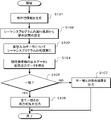
- Expected value information including time data, input data, and output data corresponding to a timing chart that defines sequence control is generated (S101).
- an execution cycle of the sequence program is set, and a matching interval is set from the execution cycle (S102).
- the virtual input data based on the execution period of the sequence program and the input data of the expected value information is processed by the sequence program (S103).
- the obtained virtual output data and the output data of the expected value information are compared using the matching section (S104). If all the output data match as a result of collation (YES in S105), the result is output (S106).
- the data matching device includes the expected value information generation unit 31 that generates expected value information including time data, input data, and output data corresponding to the timing chart that defines the sequence control, and the sequence Control for executing sequence program processing and outputting virtual output data for virtual input data based on an execution cycle setting unit 32 that sets the execution cycle of the program, the execution cycle of the sequence program, and the input data of the expected value information.
- a matching interval setting unit 33 for setting a matching interval having a time width based on the time of at least one of the output data in matching the output data of the virtual output data and the expected value information; , and an expected value matching unit 4 for matching the virtual output data with the output data of the expected value information.
- Embodiment 2 A PLC 1 according to Embodiment 2 will be described.
- the PLC 1 includes a collation enable/disable setting unit 5 in addition to the configuration disclosed in the first embodiment.
- the collation enable/disable setting unit 5 sets whether or not to collate the output data of the expected value information in the expected value collating unit 4 with the virtual output data.
- the expected value matching unit 4 does not perform matching for outputs set to not be matched by the matching permission/non-matching setting unit 5 .
- the output set to be collated by the collation enable/disable setting unit 5 is collated by the expected value collation unit 4, and the collation result is output.
- the sequence program When changing the contents of a sequence program due to a change in the specifications of a control device, etc., the sequence program has a part for existing control and a part for control after change.
- the expected value information corresponding to the existing control-oriented portion can be used as it is, but if the expected value information is used for the changed control-oriented portion, the matching result will not match. For this reason, the collation enable/disable setting unit 5 is set so as not to collate the output data of the control portion after the change due to the change of the sequence program.
- a degradation test can be performed on the modified sequence program to verify the effect of the modified sequence program on the existing control portion.
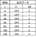
- FIG. 11 is a diagram showing an example of a timing chart. A case of changing the timing chart of FIG. 2 to the timing chart of FIG. 11 will be described as an example.
- the output Y1 is turned ON 130 ms after the input X0 is turned ON.
- the data register D0 counts the number of times the input X1 is switched between ON and OFF under the condition that the input X0 is ON, and stores it as a device value.
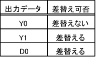
- FIG. 12 is a diagram showing an example of collation enable/disable setting. Due to the change in the sequence program, the output Y0 remains unchanged from the existing control, but the outputs Y1 and D0 are changed from the existing control.
- the collation enable/disable setting unit 5 sets the expected value collating unit 4 not to collate the output data of the expected value information and the virtual output data for the outputs Y1 and D0. As a result, the output data of the expected value information and the virtual output data are compared only for the output Y0 corresponding to the existing control portion of the sequence program.
- the collation enable/disable setting unit 5 has a function of analyzing the existing control portion and the changed control portion from the sequence program before and after the change, and detecting the output corresponding to them. can be In this case, the user's workload for specifying the target output can be reduced.
- expected value information is generated (S201).
- whether or not the output can be collated is set for the existing control portion and the changed control portion (S202).
- the existing control portion is set to "verify”
- the changed control portion is set to "do not verify”.
- the execution cycle of the sequence program after the change is set, and the matching interval is set from the execution cycle (S203).
- the processing of the sequence program is executed for the virtual input data based on the execution cycle of the sequence program after the change and the input data of the expected value information (S204).
- the obtained virtual output data and the output data of the expected value information set to be matched are matched using the matching interval (S205). If all the output data match as a result of collation (YES in S206), the result is output (S207). On the other hand, if the matching results in a mismatch (NO in S206), the user is notified of the mismatch result (S208).
- the data collation apparatus in the second embodiment has, in addition to the configuration of the first embodiment, a collation enable/disable setting unit 5 for setting whether collation between the output data of the expected value information and the virtual output data can be executed.
- the expected value matching unit 4 has a configuration for matching the output data of the expected value information and the virtual output data based on whether the matching is set to be executable.
- Embodiment 3 A PLC 1 according to Embodiment 3 will be described.
- a replacement data generation unit 34 and a replacement data setting unit 6 are provided.
- the replacement data generation unit 34 When changing the contents of a sequence program due to a change in the specifications of a control device, etc., there will be an existing control part that will not be changed in the sequence program and a control part after the change.
- the expected value information corresponding to the existing control-oriented portion can be used as it is, but if the expected value information is used for the changed control-oriented portion, the matching result will not match. Therefore, when the sequence program is changed, the replacement data generation unit 34 generates replacement data, which is expected value information including time data and output data corresponding to the timing chart that defines the sequence control after the change. .
- the replacement data setting unit 6 sets replacement data for the expected value information generated by the expected value information generation unit 31 for the sequence program before change.
- the expected value collation unit 4 collates the output data of the virtual output data, the replacement data, and the expected value information in the set collation interval.
- the replacement data is not limited to time data and output data, and may include input data.
- the partial replacement of the expected value information by the replacement data includes not only the time data and the output data but also the input data.
- FIG. 15 is a diagram showing an example of replacement data. 2 to FIG. 11 due to a change in the sequence program, the expected value information generated by the expected value information generating unit 31 for the sequence program before the change is used as it is for the output Y0, which is the existing part for control. Available. On the other hand, the outputs Y1 and D0 corresponding to the control portion after the change due to the change of the sequence program use replacement data.
- the replacement data is created to partially replace the output data of the expected value information, and the expected value information is used as it is for the input data.
- FIG. 16 is a diagram showing an example of replacement data settings.
- the output Y0 is set to "do not replace”.
- the expected value matching unit 4 reads the expected value information generated by the expected value information generating unit 31 as it is, and performs matching with the virtual output data.
- the outputs Y1 and D0 are set to "replace”. In this case, the expected value matching unit 4 reads the replacement data and performs matching with the virtual output data.
- the replacement of the expected value information with the replacement data may be performed by overwriting a part of the expected value information with the replacement data and integrating it, or without integrating the replacement data and the expected value information, the expected value matching unit 4 may read the part necessary for matching in accordance with the setting of the replacement data setting unit 6 .
- expected value information and replacement data are generated in advance (S301, S302).
- part of the expected value information is replaced with replacement data according to the setting of the replacement data setting unit 6 (S303).
- An execution cycle of the sequence program after the change is set, and a matching interval is set from the execution cycle (S304).
- the processing of the sequence program is executed for the virtual input data based on the execution cycle of the sequence program after the change and the input data of the expected value information (S305).
- the obtained virtual output data, replacement data, and expected value information output data are collated within the collation section (S306).
- the data matching device has time data corresponding to the timing chart defining the sequence control after the change, output A replacement data generation unit 34 for generating expected value information including data, and a replacement data setting unit for setting replacement data to replace the expected value information generated by the expected value information generation unit 31 for the sequence program before change. 6, and the expected value matching unit 4 has a configuration for matching the output data of the virtual output data, the replacement data, and the expected value information in the set matching interval.
- FIG. 18 is a diagram showing a modification of the hardware configuration of the control section 2 according to Embodiments 1-3. 1, 10, and 14, it has been explained that the control unit 2 has a processor 21 and a storage unit 22, and that the processor 21 executes a user program including a sequence program stored in the storage unit 22, other software, and firmware. .
- the control unit 2 may be realized by dedicated hardware (processing circuit 20). For example, single circuits, multiple circuits, programmed processors, parallel programmed processors, ASICs (Application Specific Integrated Circuits), FPGAs (Field-Programmable Gate Arrays), or combinations thereof.
- the functions of the data matching device may be partly realized by the dedicated hardware and partly realized by the configuration of the processor 21 and the storage unit 22 shown in FIGS.
Landscapes
- Physics & Mathematics (AREA)
- General Physics & Mathematics (AREA)
- Engineering & Computer Science (AREA)
- Automation & Control Theory (AREA)
- Programmable Controllers (AREA)
Priority Applications (4)
| Application Number | Priority Date | Filing Date | Title |
|---|---|---|---|
| JP2021577648A JP7113988B1 (ja) | 2021-02-17 | 2021-02-17 | データ照合装置、データ照合システム、及びデータ照合方法 |
| CN202180088713.6A CN116710858B (zh) | 2021-02-17 | 2021-02-17 | 数据核对装置、数据核对系统以及数据核对方法 |
| PCT/JP2021/005884 WO2022176054A1 (ja) | 2021-02-17 | 2021-02-17 | データ照合装置、データ照合システム、及びデータ照合方法 |
| DE112021005655.7T DE112021005655B4 (de) | 2021-02-17 | 2021-02-17 | Datenvergleichsgerät, Datenvergleichssystem und Datenvergleichsverfahren |
Applications Claiming Priority (1)
| Application Number | Priority Date | Filing Date | Title |
|---|---|---|---|
| PCT/JP2021/005884 WO2022176054A1 (ja) | 2021-02-17 | 2021-02-17 | データ照合装置、データ照合システム、及びデータ照合方法 |
Publications (1)
| Publication Number | Publication Date |
|---|---|
| WO2022176054A1 true WO2022176054A1 (ja) | 2022-08-25 |
Family
ID=82740437
Family Applications (1)
| Application Number | Title | Priority Date | Filing Date |
|---|---|---|---|
| PCT/JP2021/005884 Ceased WO2022176054A1 (ja) | 2021-02-17 | 2021-02-17 | データ照合装置、データ照合システム、及びデータ照合方法 |
Country Status (4)
| Country | Link |
|---|---|
| JP (1) | JP7113988B1 (https=) |
| CN (1) | CN116710858B (https=) |
| DE (1) | DE112021005655B4 (https=) |
| WO (1) | WO2022176054A1 (https=) |
Families Citing this family (2)
| Publication number | Priority date | Publication date | Assignee | Title |
|---|---|---|---|---|
| CN118672202B (zh) * | 2024-07-25 | 2026-03-17 | 哈尔滨宇龙自动化有限公司 | 一种plc控制器数据收发调节方法及系统 |
| JP7840498B1 (ja) * | 2024-12-18 | 2026-04-03 | 三菱電機株式会社 | シミュレーションシステム、シミュレーション方法およびシミュレーションプログラム |
Citations (6)
| Publication number | Priority date | Publication date | Assignee | Title |
|---|---|---|---|---|
| JPS6368904A (ja) * | 1986-09-10 | 1988-03-28 | Asahi Chem Ind Co Ltd | プログラマブルコントロ−ラのチエツク方法及び装置 |
| JPH0511835A (ja) * | 1991-07-08 | 1993-01-22 | Omron Corp | 故障診断装置 |
| JPH05189026A (ja) * | 1991-06-25 | 1993-07-30 | Matsushita Electric Works Ltd | 設備故障診断方法 |
| JPH1097318A (ja) * | 1996-09-20 | 1998-04-14 | Matsushita Electric Works Ltd | 自動化設備システムに於ける異常診断基準パターンの作成方法およびその基準パターンを用いた自動診断装置 |
| JPH10254510A (ja) * | 1997-03-07 | 1998-09-25 | Meidensha Corp | シーケンサ |
| JP2002163020A (ja) * | 2000-11-27 | 2002-06-07 | Matsushita Electric Works Ltd | プログラマブルコントローラにおける異常検出方法およびその装置 |
Family Cites Families (7)
| Publication number | Priority date | Publication date | Assignee | Title |
|---|---|---|---|---|
| US5951704A (en) * | 1997-02-19 | 1999-09-14 | Advantest Corp. | Test system emulator |
| JP4550641B2 (ja) | 2005-03-30 | 2010-09-22 | 大陽日酸エンジニアリング株式会社 | データ照合装置及び方法 |
| CN103246596A (zh) * | 2012-02-06 | 2013-08-14 | 镇江灵芯软件实验室有限公司 | 一种对基于时间控制的plc程序自动测试的方法 |
| CN104881363B (zh) * | 2015-06-24 | 2017-12-12 | 中国航空工业集团公司西安飞机设计研究所 | 一种控制律软件的测试方法 |
| JP6770802B2 (ja) * | 2015-12-28 | 2020-10-21 | 川崎重工業株式会社 | プラント異常監視方法およびプラント異常監視用のコンピュータプログラム |
| CN109643095A (zh) * | 2017-06-23 | 2019-04-16 | 三菱电机株式会社 | 程序验证系统、控制装置及程序验证方法 |
| CN110471394B (zh) * | 2019-07-30 | 2020-10-20 | 中车青岛四方机车车辆股份有限公司 | 任务测试方法及装置、系统、存储介质和处理器 |
-
2021
- 2021-02-17 CN CN202180088713.6A patent/CN116710858B/zh active Active
- 2021-02-17 DE DE112021005655.7T patent/DE112021005655B4/de active Active
- 2021-02-17 JP JP2021577648A patent/JP7113988B1/ja active Active
- 2021-02-17 WO PCT/JP2021/005884 patent/WO2022176054A1/ja not_active Ceased
Patent Citations (6)
| Publication number | Priority date | Publication date | Assignee | Title |
|---|---|---|---|---|
| JPS6368904A (ja) * | 1986-09-10 | 1988-03-28 | Asahi Chem Ind Co Ltd | プログラマブルコントロ−ラのチエツク方法及び装置 |
| JPH05189026A (ja) * | 1991-06-25 | 1993-07-30 | Matsushita Electric Works Ltd | 設備故障診断方法 |
| JPH0511835A (ja) * | 1991-07-08 | 1993-01-22 | Omron Corp | 故障診断装置 |
| JPH1097318A (ja) * | 1996-09-20 | 1998-04-14 | Matsushita Electric Works Ltd | 自動化設備システムに於ける異常診断基準パターンの作成方法およびその基準パターンを用いた自動診断装置 |
| JPH10254510A (ja) * | 1997-03-07 | 1998-09-25 | Meidensha Corp | シーケンサ |
| JP2002163020A (ja) * | 2000-11-27 | 2002-06-07 | Matsushita Electric Works Ltd | プログラマブルコントローラにおける異常検出方法およびその装置 |
Also Published As
| Publication number | Publication date |
|---|---|
| JP7113988B1 (ja) | 2022-08-05 |
| CN116710858B (zh) | 2024-05-03 |
| CN116710858A (zh) | 2023-09-05 |
| DE112021005655B4 (de) | 2025-09-18 |
| JPWO2022176054A1 (https=) | 2022-08-25 |
| DE112021005655T5 (de) | 2023-08-10 |
Similar Documents
| Publication | Publication Date | Title |
|---|---|---|
| JP7113988B1 (ja) | データ照合装置、データ照合システム、及びデータ照合方法 | |
| US5901073A (en) | Method for detecting errors in models through restriction | |
| US20110145799A1 (en) | Path-sensitive dataflow analysis including path refinement | |
| WO2017038290A1 (ja) | 検証システム、検証装置、及び、車両制御装置 | |
| CN104854465A (zh) | 使用数据相依性电路路径响应的唯一且不可仿制的平台识别符 | |
| CN120409376A (zh) | 回归测试方法、系统、计算机设备和可读存储介质 | |
| KR20130139221A (ko) | 반도체 프로세스 레시피들의 자동화된 검증을 위한 방법 및 장치 | |
| TWI732775B (zh) | 用於資料處理的裝置、方法、電腦軟體、儲存媒體及虛擬機 | |
| WO2021186685A1 (ja) | シミュレーション実行システム、シミュレーション実行方法およびシミュレーション実行プログラム | |
| JP2002163020A (ja) | プログラマブルコントローラにおける異常検出方法およびその装置 | |
| US20250130928A1 (en) | Automated generation of test code for testing embedded software | |
| US7532526B2 (en) | Method and system for testing address lines | |
| CN111104334B (zh) | 基于eeprom模块接口软件的测试方法、装置及可读取存储介质 | |
| WO2019142266A1 (ja) | テストケース生成装置、テストケース生成方法およびテストケース生成プログラム | |
| KR101968544B1 (ko) | 소프트웨어 취약점 검출 방법 및 장치 | |
| US20050149806A1 (en) | Failure detection simulation system | |
| US20160070846A1 (en) | System for testing ic design | |
| US20100077383A1 (en) | Simulation method and storage medium for storing program | |
| JP6620653B2 (ja) | プラント監視制御システム用エミュレータ | |
| US11531764B2 (en) | Assessing operational stability of computer system by integrity checking of computer program | |
| US10585650B1 (en) | Method and system for generating program code | |
| JP4952317B2 (ja) | 退避データ判別方法、退避データ判別プログラムおよび退避データ判別装置 | |
| US11403077B2 (en) | Method and system for preparing block diagrams for code generation | |
| JP6147094B2 (ja) | 情報処理装置及び情報処理方法及びプログラム | |
| JP2009223861A (ja) | 論理検証システム |
Legal Events
| Date | Code | Title | Description |
|---|---|---|---|
| ENP | Entry into the national phase |
Ref document number: 2021577648 Country of ref document: JP Kind code of ref document: A |
|
| 121 | Ep: the epo has been informed by wipo that ep was designated in this application |
Ref document number: 21926494 Country of ref document: EP Kind code of ref document: A1 |
|
| WWE | Wipo information: entry into national phase |
Ref document number: 202180088713.6 Country of ref document: CN |
|
| 122 | Ep: pct application non-entry in european phase |
Ref document number: 21926494 Country of ref document: EP Kind code of ref document: A1 |
|
| WWG | Wipo information: grant in national office |
Ref document number: 112021005655 Country of ref document: DE |