WO2022176002A1 - 計測機器用の超音波振動子 - Google Patents
計測機器用の超音波振動子 Download PDFInfo
- Publication number
- WO2022176002A1 WO2022176002A1 PCT/JP2021/005621 JP2021005621W WO2022176002A1 WO 2022176002 A1 WO2022176002 A1 WO 2022176002A1 JP 2021005621 W JP2021005621 W JP 2021005621W WO 2022176002 A1 WO2022176002 A1 WO 2022176002A1
- Authority
- WO
- WIPO (PCT)
- Prior art keywords
- piezoelectric element
- ultrasonic transducer
- vibrating
- frequency band
- measuring equipment
- Prior art date
- Legal status (The legal status is an assumption and is not a legal conclusion. Google has not performed a legal analysis and makes no representation as to the accuracy of the status listed.)
- Ceased
Links
Images








Classifications
-
- G—PHYSICS
- G01—MEASURING; TESTING
- G01S—RADIO DIRECTION-FINDING; RADIO NAVIGATION; DETERMINING DISTANCE OR VELOCITY BY USE OF RADIO WAVES; LOCATING OR PRESENCE-DETECTING BY USE OF THE REFLECTION OR RERADIATION OF RADIO WAVES; ANALOGOUS ARRANGEMENTS USING OTHER WAVES
- G01S7/00—Details of systems according to groups G01S13/00, G01S15/00, G01S17/00
- G01S7/52—Details of systems according to groups G01S13/00, G01S15/00, G01S17/00 of systems according to group G01S15/00
- G01S7/521—Constructional features
-
- H—ELECTRICITY
- H04—ELECTRIC COMMUNICATION TECHNIQUE
- H04R—LOUDSPEAKERS, MICROPHONES, GRAMOPHONE PICK-UPS OR LIKE ACOUSTIC ELECTROMECHANICAL TRANSDUCERS; ELECTRIC HEARING AIDS; PUBLIC ADDRESS SYSTEMS
- H04R17/00—Piezoelectric transducers; Electrostrictive transducers
Definitions
- the present invention relates to an ultrasonic transducer for measuring equipment that transmits and receives ultrasonic waves.
- Sonar that detects an object to be detected such as a school of fish by transmitting and receiving ultrasonic waves.
- Sonar consists of an ultrasonic transducer that transmits and receives ultrasonic waves, and a mechanism that causes the ultrasonic transducer to rotate around a vertical rotation axis and tilt around a tilting axis perpendicular to the rotation axis. It is a measuring instrument with By transmitting/receiving ultrasonic waves while moving the ultrasonic transducer, underwater can be detected. Then, the result of underwater detection is displayed on the screen as a detected image.
- An ultrasonic transducer generally includes an acoustic matching layer and a piezoelectric element bonded to the acoustic matching layer.
- an ultrasonic transducer for sonar uses a disk-shaped piezoelectric element, and the frequency band of ultrasonic waves is narrow.
- interference with other ships is becoming more likely to occur.
- a plurality of grooves 193 extending in the same direction are formed in a piezoelectric element 192 constituting an ultrasonic transducer 191, and the grooves 193 It has been proposed to dispose a plurality of vibrating portions 194 via the (see, for example, Patent Literature 1). By doing so, each vibrating portion 194 is easily deformed in the thickness direction of the piezoelectric element 192, so that the piezoelectric element 192 is easily deformed at each site. As a result, the piezoelectric element 192 is more likely to vibrate, increasing the electromechanical coupling coefficient and widening the frequency band.
- JP 2016-213666 A paragraph [0023], FIGS. 1, 3, 4A, etc.
- Patent Document 1 is a technique that makes it easy to vibrate the piezoelectric element 192 mainly in the thickness direction, it is difficult to say that a sufficient frequency band suitable for transmitting and receiving ultrasonic waves is obtained. Therefore, it is required to widen the frequency band of ultrasonic waves.
- the present invention has been made in view of the above problems, and an object of the present invention is to provide an ultrasonic transducer for measuring equipment capable of widening a frequency band suitable for transmitting and receiving ultrasonic waves.
- the invention according to claim 1 provides an ultrasonic transducer for a measuring instrument that transmits and receives ultrasonic waves, which has a substantially circular outer shape and a base material that also serves as an acoustic matching layer. and a piezoelectric element having a substantially circular outer shape and having a front surface bonded to the substrate and an opposite back surface, the piezoelectric elements communicating with each other at a central portion and A plurality of radially extending grooves are formed, and a plurality of generally fan-shaped vibrating portions are arranged through the grooves.
- the piezoelectric element vibrates in the thickness direction in a first frequency band
- the gist of the present invention is an ultrasonic transducer for measuring equipment, characterized by vibrating in a second frequency band lower than the first frequency band in the radial direction of the vibrating portion.
- each vibrating portion is easily deformed in the height direction.
- the piezoelectric element is more likely to vibrate in the thickness direction, resulting in a higher electromechanical coupling coefficient and a higher transmission/reception sensitivity in the first frequency band, which is the frequency band of vibration in the thickness direction. range is also widened.
- the substantially fan-shaped vibrating portion is obtained by forming the radial grooves in the piezoelectric element, when the vibrating portion is driven at the resonance frequency of the radial vibration, the end of the vibrating portion on the central side, that is, the substantially circular The amplitude becomes large at the central portion of the shaped ultrasonic transducer. As a result, the transmission/reception sensitivity of the second frequency band, which is the frequency band of radial vibration of the vibrating portion, is increased. As described above, high-sensitivity transmission and reception can be performed in both the thickness direction vibration and the radial direction vibration.
- substrate having a substantially circular outer shape includes not only a substrate having a circular outer shape, but also a substrate having an elliptical outer shape, a substrate having an oval outer shape, and the like. shall be taken.
- piezoelectric element having a substantially circular outer shape includes not only a piezoelectric element having a circular outer shape, but also a piezoelectric element having an elliptical outer shape, a piezoelectric element having an elliptical outer shape, and the like. shall be taken.
- the invention according to claim 2 is the piezoelectric element according to claim 1, wherein the piezoelectric element has a substantially annular shape having a through hole in the central portion, and the inner wall surface of the through hole The gist of this is that it constitutes the end face on the central portion side.
- the piezoelectric element has a substantially annular shape with a through hole in the center, so that the end of the vibrating portion on the center side is formed of a surface and is not sharp. Therefore, chipping of the vibrating portion can be prevented.
- the invention according to claim 3 is based on claim 1 or 2, wherein the plurality of vibrating portions include one or more first vibrating portions having a first radial length, and one or more second vibrating portions having a second radial length shorter than the first radial length; and one or more third vibrating portions having a third radial length longer than the first radial length.
- the gist of it is to include
- the plurality of vibrating portions includes three types of vibrating portions having different radial lengths.
- the individual resonance frequencies are different, and the frequency band in which the radial vibration occurs is slightly shifted up and down. (second frequency band) becomes wider. Therefore, the frequency band of ultrasonic waves is further widened.
- the gist of the invention according to claim 4 is that in any one of claims 1 to 3, the intersections of the plurality of grooves are eccentric from the center of the piezoelectric element.
- the fourth aspect of the present invention it is possible to obtain a plurality of types of vibrating portions having different radial lengths by eccentrically displacing the intersections of the plurality of grooves from the center of the piezoelectric element.
- the individual resonance frequencies are different, and the frequency band in which the radial vibration occurs is slightly shifted. 2 frequency band) becomes wider. Therefore, the frequency band of ultrasonic waves is further widened.
- eccentrically eccentrically intersecting the grooves it is possible to obtain a plurality of types of vibrating portions having different radial lengths even if the outer shape is circular.
- the invention according to claim 5 is the piezoelectric element according to claim 4, wherein the piezoelectric element has a perfect circular outer shape, and the intersection point has a length of 1% or more and 10% or less of the outer diameter of the piezoelectric element.
- the gist is that the piezoelectric element is eccentric from the center.
- the intersection of the plurality of grooves is offset from the center of the piezoelectric element by a length of 1% or more and 10% or less of the outer diameter of the piezoelectric element. It is possible to obtain a plurality of types of vibrating portions with different values. In this case, although radial vibration occurs in each vibrating part, the individual resonance frequencies are different, and the frequency band in which the radial vibration occurs is slightly shifted. 2 frequency band) becomes wider. Therefore, the frequency band of ultrasonic waves is further widened.
- the piezoelectric element has a substantially elliptical outer shape.
- the plurality of vibrating portions include a plurality of types of vibrating portions having different lengths in the radial direction.
- the individual resonance frequencies are different, and the frequency band in which the radial vibration occurs is slightly shifted. 2 frequency band) becomes wider. Therefore, the frequency band of ultrasonic waves is further widened.
- a seventh aspect of the invention provides the piezoelectric element according to any one of the first to sixth aspects, wherein the outer diameter of the piezoelectric element is at least twice the thickness of the piezoelectric element.
- the vibrating portion extending from the central portion of the piezoelectric element toward the outer peripheral side vibrates in the radial direction. It has an elongated shape that is easy to hold. As a result, the electromechanical coupling coefficient reliably increases, so that the range of the second frequency band, which is the frequency band of the radial vibration, can be reliably widened.
- the invention according to claim 8 is characterized in that, in any one of claims 1 to 7, eight or more of the vibrating portions are arranged in the piezoelectric element via the groove portions. do.
- the width of each vibrating portion becomes small, so that each vibrating portion extends in the height direction. It becomes a shape that is easy to vibrate. That is, since the piezoelectric element has a shape that easily vibrates in the thickness direction, the electromechanical coupling coefficient can be increased, the sensitivity of the first frequency band, which is the frequency band of vibration in the thickness direction, is increased, and the band is widened. can do.
- an ultrasonic transducer for measuring equipment capable of widening the frequency band suitable for transmitting and receiving ultrasonic waves.
- FIG. 1 is a schematic cross-sectional view showing a sonar of a first embodiment; FIG. Schematic cross-sectional view showing a sonar.
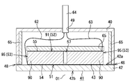
- FIG. 2 is a schematic cross-sectional view showing an ultrasonic transducer housed in a case; FIG. 2 is a plan view showing an ultrasonic transducer; FIG. 2 is a side view showing an ultrasonic transducer; Sectional drawing which shows a vibration part. The perspective view which shows a vibrating part.
- FIG. 8 is a plan view showing an ultrasonic transducer in a second embodiment; The perspective view which shows the vibration part of 2nd Embodiment.
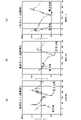
- FIG. 4 is a graph showing the relationship between frequency and impedance in sample A; 4 is a graph showing the relationship between frequency and impedance in sample B; (a) is a perspective view conceptually showing the ultrasonic transducer of Example 1, (b) is a perspective view conceptually showing the ultrasonic transducer of Example 2, and (c) is a comparative example.
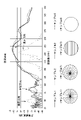
- 1 is a perspective view conceptually showing an ultrasonic transducer; FIG. (a) is a graph showing the relationship between frequency and impedance in Example 1, (b) is a graph showing the relationship between frequency and impedance in Example 2, and (c) is a graph showing the relationship between frequency and impedance in Comparative Example. Graph showing the relationship between , and impedance.
- FIG. 4 is a graph showing the relationship between frequency and transmission/reception sensitivity for samples 1 to 4;
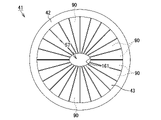
- FIG. 10 is a plan view showing an ultrasonic transducer according to another embodiment;
- FIG. 10 is a plan view showing an ultrasonic transducer according to another embodiment;
- (a) and (b) are schematic plan views showing an ultrasonic transducer according to another embodiment.
- FIG. 10 is a plan view showing an ultrasonic transducer according to another embodiment;
- FIG. 4 is a perspective view showing the ultrasonic transducer when viewed from the substrate side;
- FIG. 2 is a plan view of a main part showing a piezoelectric element in the prior art; Sectional drawing which shows the vibrating part in a prior art.
- the sonar 11 of this embodiment is used by being mounted on the bottom of a ship (not shown).
- the sonar 11 is a measuring device that detects an object to be detected such as a school of fish existing in water by irradiating ultrasonic waves into the water.
- the sonar 11 also has a sonar dome 20 .
- the sonar dome 20 is made of a resin material such as ABS resin (acrylonitrile-butadiene-styrene resin), and includes an upper case 21 , a lower case 22 and a lid 23 .
- the upper case 21 is a bottomed cylindrical case that is open at its lower end
- the lower case 22 is a bottomed cylindrical case that is open at its upper end.
- the lower end of the lower case 22 is dome-shaped (hemispherical).
- the cover 23 is disc-shaped and serves to close the lower opening of the upper case 21 and the upper opening of the lower case 22 .
- An upper housing space 24 is formed by the lid 23 and the upper case 21
- a lower housing space 25 is formed by the lid 23 and the lower case 22 .
- the sonar dome 20 accommodates an ultrasonic transducer 41 for the sonar 11 that transmits and receives ultrasonic waves, a case 40 that houses the ultrasonic transducer 41, and a drive mechanism 30 that moves the ultrasonic transducer 41.
- the drive mechanism 30 includes a scan motor 31, a tilt motor 32, and the like.
- the scan motor 31 is installed in the center of the lid 23 inside the upper accommodation space 24 .
- a stepping motor is used as the scan motor 31 of this embodiment.
- a rotating shaft 31 a of the scan motor 31 extends in the vertical direction and protrudes into the lower accommodation space 25 through a through hole 33 provided in the central portion of the lid 23 .
- the tip of the rotary shaft 31a is connected to the central portion of a disk-shaped support plate 34, and a support frame 35 is attached to the lower surface of the support plate 34. As shown in FIG.
- the support frame 35 is U-shaped with a pair of arms 35a.
- the case 40 is made of a resin material such as ABS resin and is formed into a bottomed cylindrical shape with one end open. Further, the case 40 is provided with a tilting shaft 36 perpendicular to the rotating shaft 31a.
- the tilting shaft 36 is divided into two tilting shaft portions 36a, and both tilting shaft portions 36a protrude in opposite directions from both ends of the case 40 (the left side and the right side in FIG. 2). Both tilting shafts 36a are fitted into through-holes provided in both arms 35a of the support frame 35 via bearings (not shown).
- the support plate 34, the support frame 35, the case 40, and the ultrasonic transducer 41 rotate around the rotary shaft 31a.
- the irradiation direction of the ultrasonic waves output from the ultrasonic transducer 41 changes along the circumferential direction of the rotating shaft 31a.
- the tilt motor 32 is attached to the upper end of the support frame 35 .
- a stepping motor is used as the tilt motor 32 of this embodiment.
- the output shaft 32a of the tilt motor 32 is arranged parallel to the pair of tilting shaft portions 36a, and a pinion gear 32b is attached to the tip portion thereof.
- the pinion gear 32 b meshes with a substantially semicircular tilt gear 37 attached to the case 40 . Therefore, when the output shaft 32a of the tilt motor 32 rotates, the pinion gear 32b and the tilt gear 37 rotate, so that the case 40 and the ultrasonic transducer 41 move about the tilt shaft 36 (tilt shaft portion 36a). Perform a tilting motion. Along with this, the irradiation angle of the ultrasonic waves output from the ultrasonic transducer 41 also changes as the ultrasonic transducer 41 tilts.
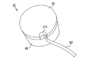
- the ultrasonic transducer 41 has a substrate 42 and a piezoelectric element 43.
- the base material 42 is a resin plate-shaped object having a substantially circular outer shape and also serving as an acoustic matching layer.
- Four projecting portions 44 are provided on the outer peripheral portion of the base material 42 , and each projecting portion 44 is provided with a screw hole 45 .
- the screw holes 45 are arranged at equal angular intervals with the center O1 of the piezoelectric element 43 (ultrasonic transducer 41) as a reference. Further, each screw hole 45 is countersunk at the opening on the back surface 42 b side of the base material 42 .
- the piezoelectric element 43 is a ceramic plate having a perfect circular outer shape and is made of, for example, lead zirconate titanate (PZT), which is a piezoelectric ceramic. As shown in FIGS. 3 to 5, the outer diameter D1 of the piezoelectric element 43 is smaller than the outer diameter of the base material 42, so the area of the base material 42 is larger than the area of the piezoelectric element 43.
- FIG. The piezoelectric element 43 also has a front surface 51 bonded to the substrate 42 , a rear surface 52 opposite to the front surface 51 , and an outer peripheral surface 53 perpendicular to the front surface 51 and the rear surface 52 . Furthermore, as shown in FIGS.
- a front side electrode 54 is formed on the front side 51 of the piezoelectric element 43 and a rear side electrode 55 is formed on the rear side 52 of the piezoelectric element 43 .
- the entire front surface 51 of the piezoelectric element 43 is bonded to the base material 42 via the front-side electrode 54 and the adhesive layer 56 (see FIG. 6).
- the piezoelectric element 43 is polarized in the thickness direction by applying a voltage between the front-side electrode 54 and the back-side electrode 55 .
- the piezoelectric element 43 has 24 grooves K1 and 24 vibrating parts 90 arranged through the grooves K1.
- the grooves K1 communicate with each other at the central portion 57 of the piezoelectric element 43 and extend radially.
- the grooves K1 are arranged at equal angular intervals with the center O1 of the piezoelectric element 43 as a reference. That is, the intersections of the grooves K1 coincide with the center O1.
- the widths of the grooves K1 are equal to each other.
- each groove K1 is not filled with a filler such as a resin material (epoxy resin, urethane resin, silicone resin, etc.) or an adhesive (epoxy adhesive, etc.), each groove K1 is entirely Generally, the gap is K0.
- a filler such as a resin material (epoxy resin, urethane resin, silicone resin, etc.) or an adhesive (epoxy adhesive, etc.)
- each vibrating portion 90 has a substantially fan shape when viewed from the rear.
- the surface 91 (back surface 52) of the vibrating portion 90 is composed of three sides 92, 93, and 94, and the side 92 has an arc shape when viewed from the back. , and sides 93 and 94 are linear when viewed from the rear.
- the outer surface 95 of each vibrating portion 90 constitutes the outer peripheral surface 53 of the piezoelectric element 43 .
- the vibrating portions 90 are connected to each other at the ends of the piezoelectric elements 43 on the front surface 51 side. Further, the radial length L0 of the substantially fan-shaped vibrating portion 90 is greater than the height H1 of the vibrating portion 90 . Note that the height H1 of the vibrating portion 90 is equal to the depth of the groove portion K1. Furthermore, the thickness of the substrate 42 described above is smaller than the height H1 of the vibrating portion 90 . Further, the thickness H2 of the portion where the vibrating portions 90 are connected to each other in the piezoelectric element 43 is smaller than the thickness of the base material 42 .
- the outer diameter D1 of the piezoelectric element 43 is two times or more the thickness H3 of the piezoelectric element 43 .
- the depth of the groove K1 is smaller than the thickness H3 of the piezoelectric element 43 and is 0.8 times or more the maximum width of the vibrating section 90 in the outer peripheral direction.
- a rear-side electrode 55 is formed on a surface 91 of each vibrating portion 90 .
- a metal foil 60 (for example, copper foil, brass foil, aluminum foil, etc.), which is a substantially circular conductive member, is attached so as to bridge each of the plurality of backside electrodes 55 .
- the metal foil 60 is attached to each rear electrode 55 using a conductive metal such as solder or a known adhesive containing a conductive filler. By attaching the metal foil 60 , the metal foil 60 becomes a common electrode for the surface 91 of each vibrating portion 90 .
- a first lead wire 62 is connected to the front electrode 54 and a second lead wire 63 is connected to the rear electrode 55, as shown in FIG.
- the first lead wire 62 is connected by soldering or the like to a side terminal (not shown) extending outward from the front electrode 54 .
- the second lead wire 63 is connected to one of the plurality of rear-side electrodes 55 by soldering or the like.
- the first lead wire 62 and the second lead wire 63 are bound by a wiring tube 64 and drawn out of the case 40 through a wire insertion hole 49 provided in the upper portion of the case 40 .
- first lead wire 62 is connected to the side terminal, a metal foil (not shown) such as copper foil is attached to the front electrode 54 and the surface 42a of the substrate 42, and the metal foil is connected to the metal foil.
- a metal foil such as copper foil is attached to the front electrode 54 and the surface 42a of the substrate 42, and the metal foil is connected to the metal foil.
- One lead wire 62 may be connected by soldering or the like.
- a sheet-like soundproof material 65 (backing material) is attached to the back surface 52 side of the piezoelectric element 43 .
- the soundproof material 65 is for suppressing reverberation, and is attached to the inner peripheral surface of the case 40 as well.
- a resin material or rubber containing particles or fibers made of metal or ceramics, or a resin material having dispersed holes (sponge or the like) is used. can be used.
- the sonar dome 20 shown in FIGS. 1 and 2 is filled with an ultrasonic wave propagating liquid (not shown) for propagating ultrasonic waves. Also, part of the ultrasonic wave propagating liquid flows into the case 40 through the communication port 48 provided in the case 40, and flows into the gap K0 (groove portion K1) between the vibrating portions 90 adjacent to each other in the piezoelectric element 43. , fills the gap K0.
- the ultrasonic wave propagating liquid of this embodiment is liquid paraffin.
- the intrinsic acoustic impedance of the base material 42 described above is smaller than the intrinsic acoustic impedance of the piezoelectric element 43, and greater than the intrinsic acoustic impedance of the ultrasonic propagating liquid and the intrinsic acoustic impedance of water.
- the sonar 11 is powered on (not shown).
- a control device (not shown) controls the ultrasonic transducer 41 to output an oscillation signal, thereby driving the ultrasonic transducer 41 .
- each vibrating portion 90 of the piezoelectric element 43 repeats contraction and expansion. Note that when the vibrating portion 90 shrinks in the height direction, the vibrating portion 90 expands in the width direction, specifically, toward the outer circumference of the vibrating portion 90 (see arrow f1 in FIG. 7) by the amount of the contracted volume. transform to become When the vibrating portion 90 expands in the height direction, the vibrating portion 90 deforms in the width direction, specifically, toward the central portion of the vibrating portion 90 (see arrow f2 in FIG. 7). As a result, the piezoelectric element 43 vibrates, and ultrasonic waves are emitted (transmitted) from the ultrasonic transducer 41 to the water.
- the ultrasonic waves when the ultrasonic waves reach an object to be detected (not shown) such as a school of fish, the ultrasonic waves are reflected by the object to be detected, become reflected waves, propagate toward the sonar 11, and are input to the ultrasonic transducer 41 ( received). After that, the ultrasonic waves (reflected waves) received by the ultrasonic transducer 41 are converted into received signals and input to the control device. At this point, the object to be detected is detected.
- control device performs control to drive the scan motor 31 and causes the ultrasonic transducer 41 to perform a turning motion about the rotating shaft 31a. Further, the control device performs control to drive the tilt motor 32 and causes the ultrasonic transducer 41 to perform tilting motion about the tilting shaft 36 .
- the irradiation direction of the ultrasonic wave gradually changes, and accordingly the detection range also gradually changes. After that, when the operator turns off the power, the irradiation of ultrasonic waves and the reception of reflected waves are terminated.
- the base material 42 is prepared. Specifically, a resin plate made of glass epoxy (FR-4) is cut into a circular shape. Also, a ceramic plate-like object to be the piezoelectric element 43 is prepared. Specifically, after producing a disk-shaped ceramic sintered body made of lead zirconate titanate (PZT), the surface is polished to obtain a ceramic plate. Next, a front-side electrode 54 is formed on the front surface 51 of the ceramic plate-like object, and a back-side electrode 55 is formed on the back surface 52 of the ceramic plate-like object. Specifically, the electrodes 54 and 55 are formed by applying a silver paste to the front surface 51 and the rear surface 52 of the ceramic plate, respectively, and firing the applied silver paste. Then, by applying a voltage between the front side electrode 54 and the back side electrode 55, a polarization process is performed to polarize the ceramic plate in the thickness direction.
- FR-4 resin plate made of glass epoxy
- FR-4 glass epoxy
- a ceramic plate is joined to one side of the substrate 42 via the front electrode 54 .
- an adhesive such as an epoxy-based adhesive
- the adhesive layer 56 is applied to either the surface of the front-side electrode 54 or the surface 42 a of the base material 42 , and the base material 42 is Adhere and fix a ceramic plate. It should be noted that brazing may be performed using solder or the like instead of applying the adhesive.
- 24 grooves K1 are formed on the back surface 52 side of the ceramic plate by performing cutting or the like.
- the ceramic plate is divided into 24 vibrating portions 90, and the rear side electrodes 55 formed on the back surface 52 of the ceramic plate are also divided into 24 pieces (the same number as the vibrating portions 90). be.
- the piezoelectric element 43 is completed. Since each vibrating portion 90 is divided while being connected to each other at the end portion of the piezoelectric element 43 on the front surface 51 side, the front electrode 54 formed on the front surface 51 is not divided.
- each rear-side electrode 55 is used as a common electrode for the surface 91 of each vibrating portion 90 .
- the ultrasonic transducer 41 is completed.
- the plurality of vibrating portions 90 are obtained by forming the grooves K1 in the piezoelectric element 43. Therefore, each vibrating portion 90 is easily deformed in the height direction. Become. As a result, the piezoelectric element 43 is more likely to vibrate in the thickness direction F1 (see FIG. 7), so that the electromechanical coupling coefficient increases and the transmission/reception sensitivity in the first frequency band, which is the frequency band of vibration in the thickness direction, increases. , and the range of the first frequency band is also widened.
- the substantially fan-shaped vibrating portion 90 is obtained by forming the radial groove portion K1 in the piezoelectric element 43, when the vibrating portion 90 is driven at the resonance frequency of the radial vibration, the end portion of the vibrating portion 90 on the central portion 57 side That is, the amplitude becomes large at the central portion of the substantially circular ultrasonic transducer 41 . As a result, the transmission/reception sensitivity of the second frequency band, which is the frequency band of radial vibration of the vibrating portion 90, is increased. As described above, high-sensitivity transmission and reception can be performed in both the thickness direction vibration and the radial direction vibration.
- the piezoelectric element 43 of the present embodiment not only vibrates in the thickness direction F1 in the first frequency band, but also vibrates in a frequency band different from the first frequency band, specifically the first frequency band. It also oscillates in radial direction F2 (see FIG. 7) in a second frequency band lower than . Therefore, if the ultrasonic transducer 41 is driven by switching between a first frequency band (e.g., around 200 kHz) vibrating in the thickness direction F1 and a second frequency band (e.g., around 50 kHz) vibrating in the radial direction F2, , ultrasonic waves can be transmitted and received in each frequency band. Further, since only one ultrasonic transducer 41 is provided in the sonar 11, ultrasonic waves can be transmitted and received in two frequency bands, so that the weight, size, and cost of the sonar 11 can be reduced.
- a first frequency band e.g., around 200 kHz
- a second frequency band e.g., around 50 kHz
- the ultrasonic transducer 41 When the ultrasonic transducer 41 is driven in the second frequency band (low-frequency drive), it is less likely to be attenuated compared to high-frequency waves, enabling deep detection and has the advantage of a wide directivity angle. , the resolution of the received signal (reflected wave) decreases. On the other hand, if the ultrasonic transducer 41 is driven (high-frequency drive) in the first frequency band, the attenuation is large and the detection depth is shallow, but detection with high resolution and a narrow directivity angle is possible. In this way, since one ultrasonic transducer 41 can be driven by switching the frequency, detection can be selected according to the situation.
- the base material 42 which also serves as the acoustic matching layer, is larger than the area of the piezoelectric element 43, ultrasonic waves can be reliably transmitted and received through the base material 42.
- the base material 42 can also be used as a support for the case 40 .
- the vibrating portions 90 forming the piezoelectric element 43 are connected to each other at the end of the piezoelectric element 43 on the front surface 51 side.
- the first lead wire 62 is connected to the front-side electrode 54 (side terminal)
- the conduction with the entire front-side electrode 54 can be ensured, so the sonar 11 can be easily manufactured.
- the entire front surface 51 of the piezoelectric element 43 is brought into contact with the surface 42a of the base material 42 by connecting the vibrating portions 90 to each other at the end portion of the piezoelectric element 43 on the front surface 51 side. Therefore, the contact area between the two is ensured, and the bonding strength between the piezoelectric element 43 and the base material 42 is improved. As a result, the reliability of the ultrasonic transducer 41 is enhanced.
- the intersection C1 between the center lines (not shown) of the plurality of grooves K1 is eccentric from the center O1 of the piezoelectric element 43. .
- the intersection C1 is eccentric from the center O1 by a length of 1% or more and 10% or less of the outer diameter D1 of the piezoelectric element 43 . Therefore, the grooves K1 are arranged at equal angular intervals around the intersection C1.
- each vibrating portion 90 has two vibrating portions 90 of 12 types with different radial lengths.
- two of the vibrating portions 90 are selected arbitrarily, excluding those having the minimum and maximum radial lengths L0, and these are defined as the first vibrating portions 101. (In FIG. 9, for example, the 7th from the shortest).
- Each first vibrating portion 101 has a first radial length L1.
- any two of the vibrating portions 90 having a second radial length L2 shorter than the first radial length L1 are selected and used as the second vibrating portions. It is defined as part 102 (in FIG. 9, for example, the shortest one (minimum value)).
- any two vibrating portions 90 having a third radial length L3 longer than the first radial length L1 are selected from among the vibrating portions 90 and used as the third vibrating portion. It is defined as part 103 (in FIG. 9, for example, the 12th (maximum value) from the shortest). Note that the radial lengths L1 to L3 of the vibrating portions 101 to 103 are larger than the heights of the vibrating portions 101 to 103, respectively.
- the vibrating portions 90 are 12 types of vibrating portions having different radial lengths L0.
- the individual resonance frequencies are different, and the frequency band in which the radial vibration occurs is slightly shifted. second frequency band) becomes wider. Therefore, the frequency band of ultrasonic waves is further widened.
- a fan-shaped vibrating portion which is a part of a piezoelectric element having a perfectly circular outer shape, was prepared. Specifically, two vibrating parts having the same center angle but different radii and thicknesses were produced, and these were used as samples A and B. As shown in FIG.
- the impedance of the vibrating portion was measured. Specifically, in each measurement sample, an impedance analyzer was used to sweep the frequency between 30 kHz and 300 kHz to measure the impedance.
- the amount of displacement in the radial direction vibration increases toward both ends (the central portion and the outer peripheral portion), and the amount of displacement in the thickness direction vibration increases toward the front surface side and the back surface side of the intermediate portion. was confirmed. Furthermore, it was confirmed that the frequency peak (resonance region) of the radial vibration in sample B, which has a larger radius of the vibrating portion than in sample A, is lower than in sample A. It was also confirmed that sample B, which has a vibrating portion thicker than sample A, has a lower frequency peak (resonance region) of the vibration in the thickness direction. It was confirmed that samples A and B both have similar waveforms.
- an ultrasonic transducer composed of a piezoelectric element and a base material was prepared. More specifically, an ultrasonic transducer 121 having a fan-shaped vibrating portion 124 formed by forming grooves 123 radially extending in a piezoelectric element 122 having a perfect circular outer shape (that is, an ultrasonic vibrator 121 of the first embodiment). An ultrasonic vibrator similar to the ultrasonic vibrator 41) was manufactured and used as Example 1 (see FIG. 12(a)).
- a piezoelectric element 122 with an outer diameter of 50 mm and a thickness of 7.2 mm is adhered to a substrate 125 (glass epoxy plate) with an outer diameter of 54 mm and a thickness of 3.6 mm, and 24 grooves 123 are bent at 15°. were formed at equal angular intervals with a pitch of .
- a fan-shaped vibrating portion 134 is formed by forming grooves 133 radially extending in a piezoelectric element 132 having a perfectly circular outer shape and eccentrically intersecting the intersections of the grooves 133 from the center of the piezoelectric element 132 .
- An ultrasonic transducer 131 (that is, an ultrasonic transducer similar to the ultrasonic transducer 41 of the second embodiment) was produced, and this was used as Example 2 (see FIG. 12B).
- a piezoelectric element 132 with an outer diameter of 50 mm and a thickness of 7.2 mm is adhered to a substrate 135 (glass epoxy plate) with an outer diameter of 54 mm and a thickness of 3 mm, and 24 grooves 133 are arranged at a pitch of 15°. formed at equal angular intervals.
- the intersection of the grooves 133 is eccentric from the center of the piezoelectric element 132 by 5 mm (that is, 10% of the outer diameter of the piezoelectric element 132).
- an ultrasonic transducer 141 having a plurality of band-shaped vibrating portions 144 formed thereon is fabricated.
- a piezoelectric element 142 with an outer diameter of 50 mm and a thickness of 7.2 mm was adhered to a base material 145 with an outer diameter of 54 mm and a thickness of 3.6 mm, and 12 grooves 143 were formed at equal intervals in parallel. .
- the impedances of the ultrasonic transducers 121, 131 and 141 were measured for Examples 1 and 2 and Comparative Example. Specifically, in each measurement sample, an impedance analyzer was used to sweep the frequency between 30 kHz and 300 kHz to measure the impedance.
- Example 1 it was confirmed that the resonance region of the vibration in the radial direction of the ultrasonic transducer 121 was near 80 kHz, and the resonance region of the vibration in the thickness direction of the ultrasonic transducer 121 was near 170 kHz ( See FIG. 13(a)). Further, in Example 2, it was confirmed that the resonance region of the ultrasonic transducer 131 in the radial direction vibration was around 70 kHz, and the resonance region of the thickness direction vibration of the ultrasonic transducer 131 was in the vicinity of 170 kHz (Fig. 13(b)).
- the ultrasonic transducers 121, 131, and 141 of Examples 1 and 2 and the comparative example all vibrate in the radial direction at a frequency lower than the frequency of vibration in the thickness direction.
- the frequencies and impedances were the same in all of Examples 1 and 2 and Comparative Example 2.
- the frequency of the comparative example was lower than the frequencies of the first and second examples, and the impedance of the comparative example was higher than the impedance of the first and second examples.
- the ultrasonic transducer 141 (comparative example) in which the groove 143 extending in one direction is formed with respect to the piezoelectric element 142, although the frequency of the vibration in the thickness direction is suitable for transmission and reception of ultrasonic waves, the frequency of the vibration in the radial direction is was found to be unsuitable for transmitting and receiving ultrasonic waves.
- An ultrasonic transducer having a fan-shaped vibrating portion (that is, similar to the ultrasonic transducer 41 of the first embodiment) is formed by forming radially extending grooves in a piezoelectric element having a circular outer shape. (Ultrasonic oscillator) was manufactured as a sample, and this was used as sample 1 (see FIG. 14). Then, a substantially circular metal foil was soldered to the ultrasonic transducer of Sample 1 so as to span the electrodes on the surface of each vibrating portion, and this was housed in a case.
- grooves extending radially are formed in the piezoelectric element having a perfect circular outer shape, and the intersection of the grooves is offset from the center of the piezoelectric element by 3 mm (here, 6% of the outer diameter of the piezoelectric element).
- an ultrasonic vibrator having a fan-shaped vibrating portion that is, an ultrasonic vibrator similar to the ultrasonic vibrator 41 of the second embodiment
- sample 2 was designated as sample 2 (see FIG. 14).
- a substantially circular metal foil was soldered to the ultrasonic transducer of Sample 2 so as to bridge each electrode on the surface of each vibrating portion, and this was housed in a case.
- an ultrasonic transducer having a plurality of band-shaped vibrating portions was fabricated. 14). Specifically, first, a piezoelectric element was adhered to a substrate, and a plurality of grooves were formed at equal intervals in parallel. Then, strip-shaped metal foil was soldered so as to span the electrodes on the surface of each vibrating portion, and this was housed in a case.
- an ultrasonic transducer having no groove formed in a piezoelectric element having a perfectly circular outer shape was experimentally produced, and this was designated as sample 4 (see FIG. 14). Specifically, first, the piezoelectric element was adhered to the substrate. Then, wiring was applied to the electrodes on the back surface of the piezoelectric element, and this was housed in a case.
- the transmission/reception sensitivity of the ultrasonic transducer was calculated for each measurement sample (samples 1 to 4). Specifically, the radiation surface of the ultrasonic transducer was immersed in water, and ultrasonic waves were perpendicularly applied to a SUS plate positioned 170 mm away from the radiation surface. Then, the ultrasonic wave (reflected wave) reflected by the SUS plate is received by the ultrasonic transducer, and a voltage signal is generated across the ultrasonic transducer. At this time, the voltage amplitude during transmission and reception of the ultrasonic transducer was measured with an oscilloscope, and the transmission/reception sensitivity was calculated by performing frequency component analysis and calculation of both the transmission voltage waveform and the reception voltage waveform.
- the transmission/reception sensitivity is the ratio of the amplitude Vr of the reception voltage to the amplitude Vs of the transmission voltage, and is calculated from the formula 20 ⁇ log(Vr/Vs). Also, the graph of FIG. 14 shows the relationship between frequency and transmission/reception sensitivity for samples 1-4.
- the piezoelectric element vibrates in the thickness direction in the first frequency band where the transmission/reception sensitivity peaks at 210 kHz.
- the second frequency band which is lower than the first frequency band and has a peak transmission/reception sensitivity at 80 kHz, oscillates in the radial direction of the vibrating portion.
- the range in which the transmission/reception sensitivity is -33 dB or more, for example, is around 135 kHz to 325 kHz in the first frequency band and around 80 kHz to 90 kHz in the second frequency band.
- both the first frequency band and the second frequency of Sample 1 are suitable for transmitting and receiving ultrasonic waves. It was also confirmed that when the grooves are formed radially, the ultrasonic transducer has a broad band around 200 kHz and a narrow band around 80 kHz.
- the piezoelectric element has a peak transmission/reception sensitivity at 220 kHz. It was confirmed that the first frequency band vibrates in the thickness direction and the radial direction of the vibrating portion vibrates in the second frequency band in which the transmission/reception sensitivity peaks at 90 kHz. It has been confirmed that the range in which the transmission/reception sensitivity is -33 dB or more, for example, is around 140 kHz to 325 kHz in the first frequency band and around 80 kHz to 90 kHz in the second frequency band. From the above, it was confirmed that both the first frequency band and the second frequency band of sample 2 are suitable for transmission and reception of ultrasonic waves, like sample 1 .
- the piezoelectric element vibrated in the thickness direction in the frequency band where the transmission/reception sensitivity peaked at 205 kHz, and at 50 kHz. It was confirmed that there was vibration in the radial direction (diameter direction) in the frequency band where the transmission/reception sensitivity peaked. It was also confirmed that the range in which the transmission/reception sensitivity is -33 dB or more, for example, is around 195 kHz to 230 kHz in the first frequency band and around 45 kHz to 55 kHz in the second frequency band.
- Sample 4 used as a comparative example is widely used in the market as a two-frequency switching type fish finder vibrator of 50 kHz and 200 kHz.
- samples 1 and 2 which are examples, have a higher sensitivity and a wider band for thickness direction vibration near 200 kHz than sample 4, and also have the same transmission/reception sensitivity as sample 4 for low-frequency radial vibration. Sensitivity is obtained and, like sample 4, can be used in both frequency bands.
- the piezoelectric element 43 has a substantially annular shape with a circular through hole 151 in the central portion 57, and the inner wall surface of the through hole 151 side end face 152 .
- the end portion of the vibrating portion 90 on the side of the central portion 57 is formed of a surface and does not become sharp, so chipping of the vibrating portion 90 can be prevented.
- the provision of the through holes 151 reduces the volume of the ceramics forming the piezoelectric element 43, thereby reducing the material cost.
- the inner diameter of the through hole 151 is preferably 1% or more and 20% or less of the outer diameter D1 of the piezoelectric element 43, for example.
- the base material 42 in addition to the piezoelectric element 43 having a substantially annular shape with a through hole 151, the base material 42 also has a circular through hole 153 in the central portion 57. may have a substantially annular shape. Note that the through hole 153 is formed in a size that does not interfere with the transmission and reception of ultrasonic waves, taking into consideration the ease of wiring work and the like.
- the ultrasonic transducer 41 of each of the above-described embodiments includes the piezoelectric element 43 having a perfectly circular outer shape, but the piezoelectric element has an elliptical outer shape (see FIG. 17(a)). or a piezoelectric element 43 (see FIG. 17(b)) having an oblong outer shape.
- the piezoelectric element 43 may have a substantially annular shape with an elliptical through hole 161 in the central portion 57, or an oval through hole (not shown) in the central portion 57. ) may have a substantially annular shape. That is, the through hole may have a non-circular shape (such as a rectangle).
- each vibrating portion 90 includes a plurality of types of vibrating portions 90 having different radial lengths. In this case, although radial vibration occurs in each vibrating portion 90, the individual resonance frequencies are different, and the frequency band in which the radial vibration occurs is slightly shifted. second frequency band) becomes wider. Therefore, the frequency band of ultrasonic waves is further widened.
- the area of the substrate 42 is larger than the area of the piezoelectric element 43 .
- the area of the substrate 42 may be equal to the area of the piezoelectric element 43 .
- the area of the base material 42 may be made smaller than the area of the piezoelectric element 43 by providing a notch 171 in the base material 42 (see FIG. 19).
- a first lead wire 62 (see FIGS. 3 and 19) is connected by soldering to the area exposed through the notch 171 of the front surface 51 (bonded surface to the base material 42) of the piezoelectric element 43. be done.
- the piezoelectric element 43 may be provided with 25 or more (for example, 30, 36, etc.) vibrating portions 90 via the grooves K1, or 23 or less (for example, 16, 12, etc.) vibrating portions 90 . , 10, 8, etc.) vibrating portions 90 may be arranged. Further, in each of the above embodiments, the piezoelectric element 43 has the vibrating portion 90 with the same central angle (15°), but the piezoelectric element 43 may have a plurality of types of vibrating portions with different central angles. good.
- the groove K1 is entirely void K0, but a part of the groove K1 may be filled with a filler.
- the internal region of the groove K1 may consist of a filled region filled with a filler (not shown) and a non-filled region not filled with the filler.
- a filling region is set at the outer end of each groove K1
- a non-filling region is set at a portion of each groove K1 excluding the outer end. and the positions of the non-filled regions are not particularly limited and can be changed as appropriate.
- the volume of the unfilled region may be larger than the volume of the filled region, smaller than the volume of the filled region, or equal to the volume of the filled region.
- the entire inner region of each groove K1 may be filled with a filler.
- the specific gravity of the filler is preferably 1.5 or less. By doing so, the filler becomes relatively light, so that the filler is less likely to be a load of vibration of the vibrating portion 90 . As a result, it is possible to prevent a decrease in transmission/reception sensitivity due to the filler.
- the piezoelectric element 43 of each of the above-described embodiments has a structure in which a plurality of divided vibrating portions 90 are connected to each other at the ends on the front surface 51 side.
- the piezoelectric element may have a structure in which a plurality of vibrating portions are completely divided.
- the ultrasonic transducer is configured by attaching each vibrating portion to the base material 42 respectively.
- the piezoelectric element 43 made of lead zirconate titanate (PZT) is used in the ultrasonic transducer 41 of each of the above embodiments, but the material for forming the piezoelectric element 43 is not particularly limited.
- PZT lead zirconate titanate
- the material for forming the piezoelectric element 43 is not particularly limited.
- potassium sodium niobate (alkali niobate), barium titanate, PMN-PT (Pb (Mg 1/3 Nb 2/3 )O 3 —PbTiO 3 ) single crystal, PZNT (Pb(Zn 1/3 Nb 2/3 )O 3 —PbTiO 3 ) single crystal, LiNbO 3 single crystal piezoelectric element. may be used.
- the base material 42 made of glass epoxy (FR-4) is used in the ultrasonic transducer 41 of each of the above embodiments. etc., and can be changed as appropriate.
- glass epoxy (CEM-3), polyphenyl sulfide (PPS), Duratron (registered trademark of QUADRANT group), fluorosint (registered trademark of QUADRANT group), and a substrate made of porous alumina may be used. .
- the metal foil 60 is used for electrical connection of the split back electrodes 55. Electrical connection may be made.
- the ultrasonic transducer 41 in each of the above embodiments was used in the sonar 11 that mechanically changes the irradiation direction of ultrasonic waves, but may be used in other measuring equipment.
- the ultrasonic transducer may be used in a sonar that electrically changes the irradiation direction of ultrasonic waves.
- the ultrasonic transducer may be used in a fish finder that does not change the irradiation direction of ultrasonic waves, that is, does not have the driving mechanism 30 .
- the ultrasonic transducer may be used for measuring equipment such as a probe for measuring the depth of water and an aerial sensor for measuring distance in the air.
- the depth of the groove is 0.8 times or more the maximum width of the vibrating portion in the outer peripheral direction. oscillator.
- the inner region of the groove is composed of a filled region filled with a filler and a non-filled region not filled with the filler.
Landscapes
- Engineering & Computer Science (AREA)
- Physics & Mathematics (AREA)
- Computer Networks & Wireless Communication (AREA)
- General Physics & Mathematics (AREA)
- Radar, Positioning & Navigation (AREA)
- Remote Sensing (AREA)
- Acoustics & Sound (AREA)
- Signal Processing (AREA)
- Transducers For Ultrasonic Waves (AREA)
Priority Applications (2)
| Application Number | Priority Date | Filing Date | Title |
|---|---|---|---|
| PCT/JP2021/005621 WO2022176002A1 (ja) | 2021-02-16 | 2021-02-16 | 計測機器用の超音波振動子 |
| JP2021526772A JP7294701B2 (ja) | 2021-02-16 | 2021-02-16 | 計測機器用の超音波振動子 |
Applications Claiming Priority (1)
| Application Number | Priority Date | Filing Date | Title |
|---|---|---|---|
| PCT/JP2021/005621 WO2022176002A1 (ja) | 2021-02-16 | 2021-02-16 | 計測機器用の超音波振動子 |
Publications (1)
| Publication Number | Publication Date |
|---|---|
| WO2022176002A1 true WO2022176002A1 (ja) | 2022-08-25 |
Family
ID=82931243
Family Applications (1)
| Application Number | Title | Priority Date | Filing Date |
|---|---|---|---|
| PCT/JP2021/005621 Ceased WO2022176002A1 (ja) | 2021-02-16 | 2021-02-16 | 計測機器用の超音波振動子 |
Country Status (2)
| Country | Link |
|---|---|
| JP (1) | JP7294701B2 (https=) |
| WO (1) | WO2022176002A1 (https=) |
Citations (5)
| Publication number | Priority date | Publication date | Assignee | Title |
|---|---|---|---|---|
| JPH03112540A (ja) * | 1989-09-28 | 1991-05-14 | Shimadzu Corp | 超音波探触子 |
| JPH0865792A (ja) * | 1994-08-25 | 1996-03-08 | Hitachi Ltd | 超音波トランスデューサと複合圧電材の製造方法及び複合圧電材 |
| WO2012011256A1 (ja) * | 2010-07-23 | 2012-01-26 | 日本電気株式会社 | 発振装置および電子機器 |
| JP2019114958A (ja) * | 2017-12-25 | 2019-07-11 | 第一精工株式会社 | 電気音響変換器 |
| JP6828944B1 (ja) * | 2020-04-14 | 2021-02-10 | 本多電子株式会社 | 計測機器用の超音波振動子 |
Family Cites Families (2)
| Publication number | Priority date | Publication date | Assignee | Title |
|---|---|---|---|---|
| JPS60112397A (ja) * | 1983-11-22 | 1985-06-18 | Oki Electric Ind Co Ltd | アレイ型平面振動子の製造方法 |
| JP7261429B2 (ja) | 2019-02-28 | 2023-04-20 | 本多電子株式会社 | ソナー、超音波振動子及びその製造方法 |
-
2021
- 2021-02-16 JP JP2021526772A patent/JP7294701B2/ja active Active
- 2021-02-16 WO PCT/JP2021/005621 patent/WO2022176002A1/ja not_active Ceased
Patent Citations (5)
| Publication number | Priority date | Publication date | Assignee | Title |
|---|---|---|---|---|
| JPH03112540A (ja) * | 1989-09-28 | 1991-05-14 | Shimadzu Corp | 超音波探触子 |
| JPH0865792A (ja) * | 1994-08-25 | 1996-03-08 | Hitachi Ltd | 超音波トランスデューサと複合圧電材の製造方法及び複合圧電材 |
| WO2012011256A1 (ja) * | 2010-07-23 | 2012-01-26 | 日本電気株式会社 | 発振装置および電子機器 |
| JP2019114958A (ja) * | 2017-12-25 | 2019-07-11 | 第一精工株式会社 | 電気音響変換器 |
| JP6828944B1 (ja) * | 2020-04-14 | 2021-02-10 | 本多電子株式会社 | 計測機器用の超音波振動子 |
Also Published As
| Publication number | Publication date |
|---|---|
| JPWO2022176002A1 (https=) | 2022-08-25 |
| JP7294701B2 (ja) | 2023-06-20 |
Similar Documents
| Publication | Publication Date | Title |
|---|---|---|
| JP6732274B1 (ja) | ソナー、超音波振動子 | |
| JP7320849B2 (ja) | ソナー | |
| Wong et al. | Development of a 20-MHz wide-bandwidth PMN-PT single crystal phased-array ultrasound transducer | |
| CN111624611B (zh) | 声呐、超声波振子及其制造方法 | |
| CN113840668B (zh) | 测量设备用超声波振子 | |
| JP7269666B2 (ja) | ソナー | |
| EP2076061B1 (en) | Ultrasonic transducer | |
| JP6991613B2 (ja) | 超音波送受波器 | |
| JP2020155900A (ja) | ソナー、超音波振動子及びその製造方法 | |
| KR20190073572A (ko) | 초음파 변환기 | |
| WO2021256414A1 (ja) | 超音波センサ | |
| WO2023095829A1 (ja) | 超音波トランスデューサ | |
| JP7294701B2 (ja) | 計測機器用の超音波振動子 | |
| US7388317B2 (en) | Ultrasonic transmitting/receiving device and method for fabricating the same | |
| US11965994B2 (en) | Ultrasonic transducer for a measuring device | |
| JP7576834B2 (ja) | ソナー | |
| JP2025009156A (ja) | 計測機器用の超音波振動子及びその製造方法 | |
| JP5417633B2 (ja) | 超音波センサ | |
| WO2023032064A1 (ja) | 超音波トランスデューサー | |
| JP2023116033A (ja) | 圧電トランスデューサ | |
| JPS5944051B2 (ja) | 超音波探触子 | |
| JP2025039030A (ja) | 振動子ユニットの製造方法、及び振動子ユニット | |
| JP2023116035A (ja) | 圧電トランスデューサ | |
| JP2023116037A (ja) | 圧電トランスデューサ | |
| JPH07265308A (ja) | 超音波探触子 |
Legal Events
| Date | Code | Title | Description |
|---|---|---|---|
| ENP | Entry into the national phase |
Ref document number: 2021526772 Country of ref document: JP Kind code of ref document: A |
|
| 121 | Ep: the epo has been informed by wipo that ep was designated in this application |
Ref document number: 21926442 Country of ref document: EP Kind code of ref document: A1 |
|
| NENP | Non-entry into the national phase |
Ref country code: DE |
|
| 122 | Ep: pct application non-entry in european phase |
Ref document number: 21926442 Country of ref document: EP Kind code of ref document: A1 |