WO2022176002A1 - Ultrasonic transducer for measurement apparatus - Google Patents
Ultrasonic transducer for measurement apparatus Download PDFInfo
- Publication number
- WO2022176002A1 WO2022176002A1 PCT/JP2021/005621 JP2021005621W WO2022176002A1 WO 2022176002 A1 WO2022176002 A1 WO 2022176002A1 JP 2021005621 W JP2021005621 W JP 2021005621W WO 2022176002 A1 WO2022176002 A1 WO 2022176002A1
- Authority
- WO
- WIPO (PCT)
- Prior art keywords
- piezoelectric element
- ultrasonic transducer
- vibrating
- frequency band
- measuring equipment
- Prior art date
Links
- 238000005259 measurement Methods 0.000 title abstract description 7
- 239000000758 substrate Substances 0.000 claims abstract description 21
- 239000000463 material Substances 0.000 claims description 43
- 230000005540 biological transmission Effects 0.000 abstract description 33
- 239000000523 sample Substances 0.000 description 34
- 239000002585 base Substances 0.000 description 31
- 230000035945 sensitivity Effects 0.000 description 27
- 239000000919 ceramic Substances 0.000 description 16
- 239000011888 foil Substances 0.000 description 14
- 239000002184 metal Substances 0.000 description 14
- 229910052751 metal Inorganic materials 0.000 description 14
- 239000000945 filler Substances 0.000 description 13
- 230000000052 comparative effect Effects 0.000 description 12
- WABPQHHGFIMREM-UHFFFAOYSA-N lead(0) Chemical compound [Pb] WABPQHHGFIMREM-UHFFFAOYSA-N 0.000 description 10
- 230000002093 peripheral effect Effects 0.000 description 8
- 229920005989 resin Polymers 0.000 description 8
- 239000011347 resin Substances 0.000 description 8
- 239000004593 Epoxy Substances 0.000 description 6
- 238000001514 detection method Methods 0.000 description 6
- 229910052451 lead zirconate titanate Inorganic materials 0.000 description 6
- XLYOFNOQVPJJNP-UHFFFAOYSA-N water Substances O XLYOFNOQVPJJNP-UHFFFAOYSA-N 0.000 description 6
- 241000251468 Actinopterygii Species 0.000 description 5
- 239000000853 adhesive Substances 0.000 description 5
- 230000001070 adhesive effect Effects 0.000 description 5
- 230000008878 coupling Effects 0.000 description 5
- 238000010168 coupling process Methods 0.000 description 5
- 238000005859 coupling reaction Methods 0.000 description 5
- 239000011521 glass Substances 0.000 description 5
- 239000010410 layer Substances 0.000 description 5
- 238000000034 method Methods 0.000 description 5
- 230000001902 propagating effect Effects 0.000 description 5
- 239000007788 liquid Substances 0.000 description 4
- 230000007246 mechanism Effects 0.000 description 4
- 238000005476 soldering Methods 0.000 description 4
- 229920000122 acrylonitrile butadiene styrene Polymers 0.000 description 3
- 239000013078 crystal Substances 0.000 description 3
- HFGPZNIAWCZYJU-UHFFFAOYSA-N lead zirconate titanate Chemical compound [O-2].[O-2].[O-2].[O-2].[O-2].[Ti+4].[Zr+4].[Pb+2] HFGPZNIAWCZYJU-UHFFFAOYSA-N 0.000 description 3
- RYGMFSIKBFXOCR-UHFFFAOYSA-N Copper Chemical compound [Cu] RYGMFSIKBFXOCR-UHFFFAOYSA-N 0.000 description 2
- BQCADISMDOOEFD-UHFFFAOYSA-N Silver Chemical compound [Ag] BQCADISMDOOEFD-UHFFFAOYSA-N 0.000 description 2
- 230000004308 accommodation Effects 0.000 description 2
- 239000012790 adhesive layer Substances 0.000 description 2
- 230000008859 change Effects 0.000 description 2
- 238000004891 communication Methods 0.000 description 2
- 239000011889 copper foil Substances 0.000 description 2
- 230000007423 decrease Effects 0.000 description 2
- 238000006073 displacement reaction Methods 0.000 description 2
- 230000005484 gravity Effects 0.000 description 2
- 230000005855 radiation Effects 0.000 description 2
- 229910052709 silver Inorganic materials 0.000 description 2
- 239000004332 silver Substances 0.000 description 2
- 229910000679 solder Inorganic materials 0.000 description 2
- 239000011800 void material Substances 0.000 description 2
- 229910001369 Brass Inorganic materials 0.000 description 1
- 239000011190 CEM-3 Substances 0.000 description 1
- 229910013641 LiNbO 3 Inorganic materials 0.000 description 1
- 229910020215 Pb(Mg1/3Nb2/3)O3PbTiO3 Inorganic materials 0.000 description 1
- UCKMPCXJQFINFW-UHFFFAOYSA-N Sulphide Chemical compound [S-2] UCKMPCXJQFINFW-UHFFFAOYSA-N 0.000 description 1
- XECAHXYUAAWDEL-UHFFFAOYSA-N acrylonitrile butadiene styrene Chemical compound C=CC=C.C=CC#N.C=CC1=CC=CC=C1 XECAHXYUAAWDEL-UHFFFAOYSA-N 0.000 description 1
- 239000004676 acrylonitrile butadiene styrene Substances 0.000 description 1
- 239000003513 alkali Substances 0.000 description 1
- 229910052782 aluminium Inorganic materials 0.000 description 1
- XAGFODPZIPBFFR-UHFFFAOYSA-N aluminium Chemical compound [Al] XAGFODPZIPBFFR-UHFFFAOYSA-N 0.000 description 1
- PNEYBMLMFCGWSK-UHFFFAOYSA-N aluminium oxide Inorganic materials [O-2].[O-2].[O-2].[Al+3].[Al+3] PNEYBMLMFCGWSK-UHFFFAOYSA-N 0.000 description 1
- 238000004458 analytical method Methods 0.000 description 1
- 230000002238 attenuated effect Effects 0.000 description 1
- 229910002113 barium titanate Inorganic materials 0.000 description 1
- JRPBQTZRNDNNOP-UHFFFAOYSA-N barium titanate Chemical compound [Ba+2].[Ba+2].[O-][Ti]([O-])([O-])[O-] JRPBQTZRNDNNOP-UHFFFAOYSA-N 0.000 description 1
- 230000008901 benefit Effects 0.000 description 1
- 239000010951 brass Substances 0.000 description 1
- 238000005219 brazing Methods 0.000 description 1
- 238000004364 calculation method Methods 0.000 description 1
- 239000011231 conductive filler Substances 0.000 description 1
- 230000008602 contraction Effects 0.000 description 1
- 238000005520 cutting process Methods 0.000 description 1
- 230000000694 effects Effects 0.000 description 1
- 229920001971 elastomer Polymers 0.000 description 1
- 229920006332 epoxy adhesive Polymers 0.000 description 1
- 239000003822 epoxy resin Substances 0.000 description 1
- 238000011156 evaluation Methods 0.000 description 1
- 239000000835 fiber Substances 0.000 description 1
- 238000010304 firing Methods 0.000 description 1
- 238000003780 insertion Methods 0.000 description 1
- 230000037431 insertion Effects 0.000 description 1
- 230000001678 irradiating effect Effects 0.000 description 1
- 229940057995 liquid paraffin Drugs 0.000 description 1
- 238000004519 manufacturing process Methods 0.000 description 1
- 230000010355 oscillation Effects 0.000 description 1
- 239000002245 particle Substances 0.000 description 1
- 230000010287 polarization Effects 0.000 description 1
- 229920000647 polyepoxide Polymers 0.000 description 1
- 229920006389 polyphenyl polymer Polymers 0.000 description 1
- BITYAPCSNKJESK-UHFFFAOYSA-N potassiosodium Chemical compound [Na].[K] BITYAPCSNKJESK-UHFFFAOYSA-N 0.000 description 1
- 230000008569 process Effects 0.000 description 1
- 229920002050 silicone resin Polymers 0.000 description 1
- 229920002803 thermoplastic polyurethane Polymers 0.000 description 1
Images


Classifications
-
- G—PHYSICS
- G01—MEASURING; TESTING
- G01S—RADIO DIRECTION-FINDING; RADIO NAVIGATION; DETERMINING DISTANCE OR VELOCITY BY USE OF RADIO WAVES; LOCATING OR PRESENCE-DETECTING BY USE OF THE REFLECTION OR RERADIATION OF RADIO WAVES; ANALOGOUS ARRANGEMENTS USING OTHER WAVES
- G01S7/00—Details of systems according to groups G01S13/00, G01S15/00, G01S17/00
- G01S7/52—Details of systems according to groups G01S13/00, G01S15/00, G01S17/00 of systems according to group G01S15/00
- G01S7/521—Constructional features
-
- H—ELECTRICITY
- H04—ELECTRIC COMMUNICATION TECHNIQUE
- H04R—LOUDSPEAKERS, MICROPHONES, GRAMOPHONE PICK-UPS OR LIKE ACOUSTIC ELECTROMECHANICAL TRANSDUCERS; DEAF-AID SETS; PUBLIC ADDRESS SYSTEMS
- H04R17/00—Piezoelectric transducers; Electrostrictive transducers
Definitions
- the present invention relates to an ultrasonic transducer for measuring equipment that transmits and receives ultrasonic waves.
- Sonar that detects an object to be detected such as a school of fish by transmitting and receiving ultrasonic waves.
- Sonar consists of an ultrasonic transducer that transmits and receives ultrasonic waves, and a mechanism that causes the ultrasonic transducer to rotate around a vertical rotation axis and tilt around a tilting axis perpendicular to the rotation axis. It is a measuring instrument with By transmitting/receiving ultrasonic waves while moving the ultrasonic transducer, underwater can be detected. Then, the result of underwater detection is displayed on the screen as a detected image.
- An ultrasonic transducer generally includes an acoustic matching layer and a piezoelectric element bonded to the acoustic matching layer.
- an ultrasonic transducer for sonar uses a disk-shaped piezoelectric element, and the frequency band of ultrasonic waves is narrow.
- interference with other ships is becoming more likely to occur.
- a plurality of grooves 193 extending in the same direction are formed in a piezoelectric element 192 constituting an ultrasonic transducer 191, and the grooves 193 It has been proposed to dispose a plurality of vibrating portions 194 via the (see, for example, Patent Literature 1). By doing so, each vibrating portion 194 is easily deformed in the thickness direction of the piezoelectric element 192, so that the piezoelectric element 192 is easily deformed at each site. As a result, the piezoelectric element 192 is more likely to vibrate, increasing the electromechanical coupling coefficient and widening the frequency band.
- JP 2016-213666 A paragraph [0023], FIGS. 1, 3, 4A, etc.
- Patent Document 1 is a technique that makes it easy to vibrate the piezoelectric element 192 mainly in the thickness direction, it is difficult to say that a sufficient frequency band suitable for transmitting and receiving ultrasonic waves is obtained. Therefore, it is required to widen the frequency band of ultrasonic waves.
- the present invention has been made in view of the above problems, and an object of the present invention is to provide an ultrasonic transducer for measuring equipment capable of widening a frequency band suitable for transmitting and receiving ultrasonic waves.
- the invention according to claim 1 provides an ultrasonic transducer for a measuring instrument that transmits and receives ultrasonic waves, which has a substantially circular outer shape and a base material that also serves as an acoustic matching layer. and a piezoelectric element having a substantially circular outer shape and having a front surface bonded to the substrate and an opposite back surface, the piezoelectric elements communicating with each other at a central portion and A plurality of radially extending grooves are formed, and a plurality of generally fan-shaped vibrating portions are arranged through the grooves.
- the piezoelectric element vibrates in the thickness direction in a first frequency band
- the gist of the present invention is an ultrasonic transducer for measuring equipment, characterized by vibrating in a second frequency band lower than the first frequency band in the radial direction of the vibrating portion.
- each vibrating portion is easily deformed in the height direction.
- the piezoelectric element is more likely to vibrate in the thickness direction, resulting in a higher electromechanical coupling coefficient and a higher transmission/reception sensitivity in the first frequency band, which is the frequency band of vibration in the thickness direction. range is also widened.
- the substantially fan-shaped vibrating portion is obtained by forming the radial grooves in the piezoelectric element, when the vibrating portion is driven at the resonance frequency of the radial vibration, the end of the vibrating portion on the central side, that is, the substantially circular The amplitude becomes large at the central portion of the shaped ultrasonic transducer. As a result, the transmission/reception sensitivity of the second frequency band, which is the frequency band of radial vibration of the vibrating portion, is increased. As described above, high-sensitivity transmission and reception can be performed in both the thickness direction vibration and the radial direction vibration.
- substrate having a substantially circular outer shape includes not only a substrate having a circular outer shape, but also a substrate having an elliptical outer shape, a substrate having an oval outer shape, and the like. shall be taken.
- piezoelectric element having a substantially circular outer shape includes not only a piezoelectric element having a circular outer shape, but also a piezoelectric element having an elliptical outer shape, a piezoelectric element having an elliptical outer shape, and the like. shall be taken.
- the invention according to claim 2 is the piezoelectric element according to claim 1, wherein the piezoelectric element has a substantially annular shape having a through hole in the central portion, and the inner wall surface of the through hole The gist of this is that it constitutes the end face on the central portion side.
- the piezoelectric element has a substantially annular shape with a through hole in the center, so that the end of the vibrating portion on the center side is formed of a surface and is not sharp. Therefore, chipping of the vibrating portion can be prevented.
- the invention according to claim 3 is based on claim 1 or 2, wherein the plurality of vibrating portions include one or more first vibrating portions having a first radial length, and one or more second vibrating portions having a second radial length shorter than the first radial length; and one or more third vibrating portions having a third radial length longer than the first radial length.
- the gist of it is to include
- the plurality of vibrating portions includes three types of vibrating portions having different radial lengths.
- the individual resonance frequencies are different, and the frequency band in which the radial vibration occurs is slightly shifted up and down. (second frequency band) becomes wider. Therefore, the frequency band of ultrasonic waves is further widened.
- the gist of the invention according to claim 4 is that in any one of claims 1 to 3, the intersections of the plurality of grooves are eccentric from the center of the piezoelectric element.
- the fourth aspect of the present invention it is possible to obtain a plurality of types of vibrating portions having different radial lengths by eccentrically displacing the intersections of the plurality of grooves from the center of the piezoelectric element.
- the individual resonance frequencies are different, and the frequency band in which the radial vibration occurs is slightly shifted. 2 frequency band) becomes wider. Therefore, the frequency band of ultrasonic waves is further widened.
- eccentrically eccentrically intersecting the grooves it is possible to obtain a plurality of types of vibrating portions having different radial lengths even if the outer shape is circular.
- the invention according to claim 5 is the piezoelectric element according to claim 4, wherein the piezoelectric element has a perfect circular outer shape, and the intersection point has a length of 1% or more and 10% or less of the outer diameter of the piezoelectric element.
- the gist is that the piezoelectric element is eccentric from the center.
- the intersection of the plurality of grooves is offset from the center of the piezoelectric element by a length of 1% or more and 10% or less of the outer diameter of the piezoelectric element. It is possible to obtain a plurality of types of vibrating portions with different values. In this case, although radial vibration occurs in each vibrating part, the individual resonance frequencies are different, and the frequency band in which the radial vibration occurs is slightly shifted. 2 frequency band) becomes wider. Therefore, the frequency band of ultrasonic waves is further widened.
- the piezoelectric element has a substantially elliptical outer shape.
- the plurality of vibrating portions include a plurality of types of vibrating portions having different lengths in the radial direction.
- the individual resonance frequencies are different, and the frequency band in which the radial vibration occurs is slightly shifted. 2 frequency band) becomes wider. Therefore, the frequency band of ultrasonic waves is further widened.
- a seventh aspect of the invention provides the piezoelectric element according to any one of the first to sixth aspects, wherein the outer diameter of the piezoelectric element is at least twice the thickness of the piezoelectric element.
- the vibrating portion extending from the central portion of the piezoelectric element toward the outer peripheral side vibrates in the radial direction. It has an elongated shape that is easy to hold. As a result, the electromechanical coupling coefficient reliably increases, so that the range of the second frequency band, which is the frequency band of the radial vibration, can be reliably widened.
- the invention according to claim 8 is characterized in that, in any one of claims 1 to 7, eight or more of the vibrating portions are arranged in the piezoelectric element via the groove portions. do.
- the width of each vibrating portion becomes small, so that each vibrating portion extends in the height direction. It becomes a shape that is easy to vibrate. That is, since the piezoelectric element has a shape that easily vibrates in the thickness direction, the electromechanical coupling coefficient can be increased, the sensitivity of the first frequency band, which is the frequency band of vibration in the thickness direction, is increased, and the band is widened. can do.
- an ultrasonic transducer for measuring equipment capable of widening the frequency band suitable for transmitting and receiving ultrasonic waves.
- FIG. 1 is a schematic cross-sectional view showing a sonar of a first embodiment; FIG. Schematic cross-sectional view showing a sonar.
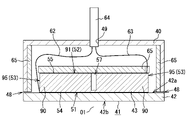
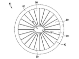
- FIG. 2 is a schematic cross-sectional view showing an ultrasonic transducer housed in a case; FIG. 2 is a plan view showing an ultrasonic transducer; FIG. 2 is a side view showing an ultrasonic transducer; Sectional drawing which shows a vibration part. The perspective view which shows a vibrating part.
- FIG. 8 is a plan view showing an ultrasonic transducer in a second embodiment; The perspective view which shows the vibration part of 2nd Embodiment.
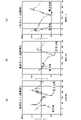
- FIG. 4 is a graph showing the relationship between frequency and impedance in sample A; 4 is a graph showing the relationship between frequency and impedance in sample B; (a) is a perspective view conceptually showing the ultrasonic transducer of Example 1, (b) is a perspective view conceptually showing the ultrasonic transducer of Example 2, and (c) is a comparative example.
- 1 is a perspective view conceptually showing an ultrasonic transducer; FIG. (a) is a graph showing the relationship between frequency and impedance in Example 1, (b) is a graph showing the relationship between frequency and impedance in Example 2, and (c) is a graph showing the relationship between frequency and impedance in Comparative Example. Graph showing the relationship between , and impedance.
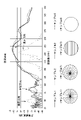
- FIG. 4 is a graph showing the relationship between frequency and transmission/reception sensitivity for samples 1 to 4;
- FIG. 10 is a plan view showing an ultrasonic transducer according to another embodiment;
- FIG. 10 is a plan view showing an ultrasonic transducer according to another embodiment;
- (a) and (b) are schematic plan views showing an ultrasonic transducer according to another embodiment.
- FIG. 10 is a plan view showing an ultrasonic transducer according to another embodiment;
- FIG. 4 is a perspective view showing the ultrasonic transducer when viewed from the substrate side;
- FIG. 2 is a plan view of a main part showing a piezoelectric element in the prior art; Sectional drawing which shows the vibrating part in a prior art.
- the sonar 11 of this embodiment is used by being mounted on the bottom of a ship (not shown).
- the sonar 11 is a measuring device that detects an object to be detected such as a school of fish existing in water by irradiating ultrasonic waves into the water.
- the sonar 11 also has a sonar dome 20 .
- the sonar dome 20 is made of a resin material such as ABS resin (acrylonitrile-butadiene-styrene resin), and includes an upper case 21 , a lower case 22 and a lid 23 .
- the upper case 21 is a bottomed cylindrical case that is open at its lower end
- the lower case 22 is a bottomed cylindrical case that is open at its upper end.
- the lower end of the lower case 22 is dome-shaped (hemispherical).
- the cover 23 is disc-shaped and serves to close the lower opening of the upper case 21 and the upper opening of the lower case 22 .
- An upper housing space 24 is formed by the lid 23 and the upper case 21
- a lower housing space 25 is formed by the lid 23 and the lower case 22 .
- the sonar dome 20 accommodates an ultrasonic transducer 41 for the sonar 11 that transmits and receives ultrasonic waves, a case 40 that houses the ultrasonic transducer 41, and a drive mechanism 30 that moves the ultrasonic transducer 41.
- the drive mechanism 30 includes a scan motor 31, a tilt motor 32, and the like.
- the scan motor 31 is installed in the center of the lid 23 inside the upper accommodation space 24 .
- a stepping motor is used as the scan motor 31 of this embodiment.
- a rotating shaft 31 a of the scan motor 31 extends in the vertical direction and protrudes into the lower accommodation space 25 through a through hole 33 provided in the central portion of the lid 23 .
- the tip of the rotary shaft 31a is connected to the central portion of a disk-shaped support plate 34, and a support frame 35 is attached to the lower surface of the support plate 34. As shown in FIG.
- the support frame 35 is U-shaped with a pair of arms 35a.
- the case 40 is made of a resin material such as ABS resin and is formed into a bottomed cylindrical shape with one end open. Further, the case 40 is provided with a tilting shaft 36 perpendicular to the rotating shaft 31a.
- the tilting shaft 36 is divided into two tilting shaft portions 36a, and both tilting shaft portions 36a protrude in opposite directions from both ends of the case 40 (the left side and the right side in FIG. 2). Both tilting shafts 36a are fitted into through-holes provided in both arms 35a of the support frame 35 via bearings (not shown).
- the support plate 34, the support frame 35, the case 40, and the ultrasonic transducer 41 rotate around the rotary shaft 31a.
- the irradiation direction of the ultrasonic waves output from the ultrasonic transducer 41 changes along the circumferential direction of the rotating shaft 31a.
- the tilt motor 32 is attached to the upper end of the support frame 35 .
- a stepping motor is used as the tilt motor 32 of this embodiment.
- the output shaft 32a of the tilt motor 32 is arranged parallel to the pair of tilting shaft portions 36a, and a pinion gear 32b is attached to the tip portion thereof.
- the pinion gear 32 b meshes with a substantially semicircular tilt gear 37 attached to the case 40 . Therefore, when the output shaft 32a of the tilt motor 32 rotates, the pinion gear 32b and the tilt gear 37 rotate, so that the case 40 and the ultrasonic transducer 41 move about the tilt shaft 36 (tilt shaft portion 36a). Perform a tilting motion. Along with this, the irradiation angle of the ultrasonic waves output from the ultrasonic transducer 41 also changes as the ultrasonic transducer 41 tilts.
- the ultrasonic transducer 41 has a substrate 42 and a piezoelectric element 43.
- the base material 42 is a resin plate-shaped object having a substantially circular outer shape and also serving as an acoustic matching layer.
- Four projecting portions 44 are provided on the outer peripheral portion of the base material 42 , and each projecting portion 44 is provided with a screw hole 45 .
- the screw holes 45 are arranged at equal angular intervals with the center O1 of the piezoelectric element 43 (ultrasonic transducer 41) as a reference. Further, each screw hole 45 is countersunk at the opening on the back surface 42 b side of the base material 42 .
- the piezoelectric element 43 is a ceramic plate having a perfect circular outer shape and is made of, for example, lead zirconate titanate (PZT), which is a piezoelectric ceramic. As shown in FIGS. 3 to 5, the outer diameter D1 of the piezoelectric element 43 is smaller than the outer diameter of the base material 42, so the area of the base material 42 is larger than the area of the piezoelectric element 43.
- FIG. The piezoelectric element 43 also has a front surface 51 bonded to the substrate 42 , a rear surface 52 opposite to the front surface 51 , and an outer peripheral surface 53 perpendicular to the front surface 51 and the rear surface 52 . Furthermore, as shown in FIGS.
- a front side electrode 54 is formed on the front side 51 of the piezoelectric element 43 and a rear side electrode 55 is formed on the rear side 52 of the piezoelectric element 43 .
- the entire front surface 51 of the piezoelectric element 43 is bonded to the base material 42 via the front-side electrode 54 and the adhesive layer 56 (see FIG. 6).
- the piezoelectric element 43 is polarized in the thickness direction by applying a voltage between the front-side electrode 54 and the back-side electrode 55 .
- the piezoelectric element 43 has 24 grooves K1 and 24 vibrating parts 90 arranged through the grooves K1.
- the grooves K1 communicate with each other at the central portion 57 of the piezoelectric element 43 and extend radially.
- the grooves K1 are arranged at equal angular intervals with the center O1 of the piezoelectric element 43 as a reference. That is, the intersections of the grooves K1 coincide with the center O1.
- the widths of the grooves K1 are equal to each other.
- each groove K1 is not filled with a filler such as a resin material (epoxy resin, urethane resin, silicone resin, etc.) or an adhesive (epoxy adhesive, etc.), each groove K1 is entirely Generally, the gap is K0.
- a filler such as a resin material (epoxy resin, urethane resin, silicone resin, etc.) or an adhesive (epoxy adhesive, etc.)
- each vibrating portion 90 has a substantially fan shape when viewed from the rear.
- the surface 91 (back surface 52) of the vibrating portion 90 is composed of three sides 92, 93, and 94, and the side 92 has an arc shape when viewed from the back. , and sides 93 and 94 are linear when viewed from the rear.
- the outer surface 95 of each vibrating portion 90 constitutes the outer peripheral surface 53 of the piezoelectric element 43 .
- the vibrating portions 90 are connected to each other at the ends of the piezoelectric elements 43 on the front surface 51 side. Further, the radial length L0 of the substantially fan-shaped vibrating portion 90 is greater than the height H1 of the vibrating portion 90 . Note that the height H1 of the vibrating portion 90 is equal to the depth of the groove portion K1. Furthermore, the thickness of the substrate 42 described above is smaller than the height H1 of the vibrating portion 90 . Further, the thickness H2 of the portion where the vibrating portions 90 are connected to each other in the piezoelectric element 43 is smaller than the thickness of the base material 42 .
- the outer diameter D1 of the piezoelectric element 43 is two times or more the thickness H3 of the piezoelectric element 43 .
- the depth of the groove K1 is smaller than the thickness H3 of the piezoelectric element 43 and is 0.8 times or more the maximum width of the vibrating section 90 in the outer peripheral direction.
- a rear-side electrode 55 is formed on a surface 91 of each vibrating portion 90 .
- a metal foil 60 (for example, copper foil, brass foil, aluminum foil, etc.), which is a substantially circular conductive member, is attached so as to bridge each of the plurality of backside electrodes 55 .
- the metal foil 60 is attached to each rear electrode 55 using a conductive metal such as solder or a known adhesive containing a conductive filler. By attaching the metal foil 60 , the metal foil 60 becomes a common electrode for the surface 91 of each vibrating portion 90 .
- a first lead wire 62 is connected to the front electrode 54 and a second lead wire 63 is connected to the rear electrode 55, as shown in FIG.
- the first lead wire 62 is connected by soldering or the like to a side terminal (not shown) extending outward from the front electrode 54 .
- the second lead wire 63 is connected to one of the plurality of rear-side electrodes 55 by soldering or the like.
- the first lead wire 62 and the second lead wire 63 are bound by a wiring tube 64 and drawn out of the case 40 through a wire insertion hole 49 provided in the upper portion of the case 40 .
- first lead wire 62 is connected to the side terminal, a metal foil (not shown) such as copper foil is attached to the front electrode 54 and the surface 42a of the substrate 42, and the metal foil is connected to the metal foil.
- a metal foil such as copper foil is attached to the front electrode 54 and the surface 42a of the substrate 42, and the metal foil is connected to the metal foil.
- One lead wire 62 may be connected by soldering or the like.
- a sheet-like soundproof material 65 (backing material) is attached to the back surface 52 side of the piezoelectric element 43 .
- the soundproof material 65 is for suppressing reverberation, and is attached to the inner peripheral surface of the case 40 as well.
- a resin material or rubber containing particles or fibers made of metal or ceramics, or a resin material having dispersed holes (sponge or the like) is used. can be used.
- the sonar dome 20 shown in FIGS. 1 and 2 is filled with an ultrasonic wave propagating liquid (not shown) for propagating ultrasonic waves. Also, part of the ultrasonic wave propagating liquid flows into the case 40 through the communication port 48 provided in the case 40, and flows into the gap K0 (groove portion K1) between the vibrating portions 90 adjacent to each other in the piezoelectric element 43. , fills the gap K0.
- the ultrasonic wave propagating liquid of this embodiment is liquid paraffin.
- the intrinsic acoustic impedance of the base material 42 described above is smaller than the intrinsic acoustic impedance of the piezoelectric element 43, and greater than the intrinsic acoustic impedance of the ultrasonic propagating liquid and the intrinsic acoustic impedance of water.
- the sonar 11 is powered on (not shown).
- a control device (not shown) controls the ultrasonic transducer 41 to output an oscillation signal, thereby driving the ultrasonic transducer 41 .
- each vibrating portion 90 of the piezoelectric element 43 repeats contraction and expansion. Note that when the vibrating portion 90 shrinks in the height direction, the vibrating portion 90 expands in the width direction, specifically, toward the outer circumference of the vibrating portion 90 (see arrow f1 in FIG. 7) by the amount of the contracted volume. transform to become When the vibrating portion 90 expands in the height direction, the vibrating portion 90 deforms in the width direction, specifically, toward the central portion of the vibrating portion 90 (see arrow f2 in FIG. 7). As a result, the piezoelectric element 43 vibrates, and ultrasonic waves are emitted (transmitted) from the ultrasonic transducer 41 to the water.
- the ultrasonic waves when the ultrasonic waves reach an object to be detected (not shown) such as a school of fish, the ultrasonic waves are reflected by the object to be detected, become reflected waves, propagate toward the sonar 11, and are input to the ultrasonic transducer 41 ( received). After that, the ultrasonic waves (reflected waves) received by the ultrasonic transducer 41 are converted into received signals and input to the control device. At this point, the object to be detected is detected.
- control device performs control to drive the scan motor 31 and causes the ultrasonic transducer 41 to perform a turning motion about the rotating shaft 31a. Further, the control device performs control to drive the tilt motor 32 and causes the ultrasonic transducer 41 to perform tilting motion about the tilting shaft 36 .
- the irradiation direction of the ultrasonic wave gradually changes, and accordingly the detection range also gradually changes. After that, when the operator turns off the power, the irradiation of ultrasonic waves and the reception of reflected waves are terminated.
- the base material 42 is prepared. Specifically, a resin plate made of glass epoxy (FR-4) is cut into a circular shape. Also, a ceramic plate-like object to be the piezoelectric element 43 is prepared. Specifically, after producing a disk-shaped ceramic sintered body made of lead zirconate titanate (PZT), the surface is polished to obtain a ceramic plate. Next, a front-side electrode 54 is formed on the front surface 51 of the ceramic plate-like object, and a back-side electrode 55 is formed on the back surface 52 of the ceramic plate-like object. Specifically, the electrodes 54 and 55 are formed by applying a silver paste to the front surface 51 and the rear surface 52 of the ceramic plate, respectively, and firing the applied silver paste. Then, by applying a voltage between the front side electrode 54 and the back side electrode 55, a polarization process is performed to polarize the ceramic plate in the thickness direction.
- FR-4 resin plate made of glass epoxy
- FR-4 glass epoxy
- a ceramic plate is joined to one side of the substrate 42 via the front electrode 54 .
- an adhesive such as an epoxy-based adhesive
- the adhesive layer 56 is applied to either the surface of the front-side electrode 54 or the surface 42 a of the base material 42 , and the base material 42 is Adhere and fix a ceramic plate. It should be noted that brazing may be performed using solder or the like instead of applying the adhesive.
- 24 grooves K1 are formed on the back surface 52 side of the ceramic plate by performing cutting or the like.
- the ceramic plate is divided into 24 vibrating portions 90, and the rear side electrodes 55 formed on the back surface 52 of the ceramic plate are also divided into 24 pieces (the same number as the vibrating portions 90). be.
- the piezoelectric element 43 is completed. Since each vibrating portion 90 is divided while being connected to each other at the end portion of the piezoelectric element 43 on the front surface 51 side, the front electrode 54 formed on the front surface 51 is not divided.
- each rear-side electrode 55 is used as a common electrode for the surface 91 of each vibrating portion 90 .
- the ultrasonic transducer 41 is completed.
- the plurality of vibrating portions 90 are obtained by forming the grooves K1 in the piezoelectric element 43. Therefore, each vibrating portion 90 is easily deformed in the height direction. Become. As a result, the piezoelectric element 43 is more likely to vibrate in the thickness direction F1 (see FIG. 7), so that the electromechanical coupling coefficient increases and the transmission/reception sensitivity in the first frequency band, which is the frequency band of vibration in the thickness direction, increases. , and the range of the first frequency band is also widened.
- the substantially fan-shaped vibrating portion 90 is obtained by forming the radial groove portion K1 in the piezoelectric element 43, when the vibrating portion 90 is driven at the resonance frequency of the radial vibration, the end portion of the vibrating portion 90 on the central portion 57 side That is, the amplitude becomes large at the central portion of the substantially circular ultrasonic transducer 41 . As a result, the transmission/reception sensitivity of the second frequency band, which is the frequency band of radial vibration of the vibrating portion 90, is increased. As described above, high-sensitivity transmission and reception can be performed in both the thickness direction vibration and the radial direction vibration.
- the piezoelectric element 43 of the present embodiment not only vibrates in the thickness direction F1 in the first frequency band, but also vibrates in a frequency band different from the first frequency band, specifically the first frequency band. It also oscillates in radial direction F2 (see FIG. 7) in a second frequency band lower than . Therefore, if the ultrasonic transducer 41 is driven by switching between a first frequency band (e.g., around 200 kHz) vibrating in the thickness direction F1 and a second frequency band (e.g., around 50 kHz) vibrating in the radial direction F2, , ultrasonic waves can be transmitted and received in each frequency band. Further, since only one ultrasonic transducer 41 is provided in the sonar 11, ultrasonic waves can be transmitted and received in two frequency bands, so that the weight, size, and cost of the sonar 11 can be reduced.
- a first frequency band e.g., around 200 kHz
- a second frequency band e.g., around 50 kHz
- the ultrasonic transducer 41 When the ultrasonic transducer 41 is driven in the second frequency band (low-frequency drive), it is less likely to be attenuated compared to high-frequency waves, enabling deep detection and has the advantage of a wide directivity angle. , the resolution of the received signal (reflected wave) decreases. On the other hand, if the ultrasonic transducer 41 is driven (high-frequency drive) in the first frequency band, the attenuation is large and the detection depth is shallow, but detection with high resolution and a narrow directivity angle is possible. In this way, since one ultrasonic transducer 41 can be driven by switching the frequency, detection can be selected according to the situation.
- the base material 42 which also serves as the acoustic matching layer, is larger than the area of the piezoelectric element 43, ultrasonic waves can be reliably transmitted and received through the base material 42.
- the base material 42 can also be used as a support for the case 40 .
- the vibrating portions 90 forming the piezoelectric element 43 are connected to each other at the end of the piezoelectric element 43 on the front surface 51 side.
- the first lead wire 62 is connected to the front-side electrode 54 (side terminal)
- the conduction with the entire front-side electrode 54 can be ensured, so the sonar 11 can be easily manufactured.
- the entire front surface 51 of the piezoelectric element 43 is brought into contact with the surface 42a of the base material 42 by connecting the vibrating portions 90 to each other at the end portion of the piezoelectric element 43 on the front surface 51 side. Therefore, the contact area between the two is ensured, and the bonding strength between the piezoelectric element 43 and the base material 42 is improved. As a result, the reliability of the ultrasonic transducer 41 is enhanced.
- the intersection C1 between the center lines (not shown) of the plurality of grooves K1 is eccentric from the center O1 of the piezoelectric element 43. .
- the intersection C1 is eccentric from the center O1 by a length of 1% or more and 10% or less of the outer diameter D1 of the piezoelectric element 43 . Therefore, the grooves K1 are arranged at equal angular intervals around the intersection C1.
- each vibrating portion 90 has two vibrating portions 90 of 12 types with different radial lengths.
- two of the vibrating portions 90 are selected arbitrarily, excluding those having the minimum and maximum radial lengths L0, and these are defined as the first vibrating portions 101. (In FIG. 9, for example, the 7th from the shortest).
- Each first vibrating portion 101 has a first radial length L1.
- any two of the vibrating portions 90 having a second radial length L2 shorter than the first radial length L1 are selected and used as the second vibrating portions. It is defined as part 102 (in FIG. 9, for example, the shortest one (minimum value)).
- any two vibrating portions 90 having a third radial length L3 longer than the first radial length L1 are selected from among the vibrating portions 90 and used as the third vibrating portion. It is defined as part 103 (in FIG. 9, for example, the 12th (maximum value) from the shortest). Note that the radial lengths L1 to L3 of the vibrating portions 101 to 103 are larger than the heights of the vibrating portions 101 to 103, respectively.
- the vibrating portions 90 are 12 types of vibrating portions having different radial lengths L0.
- the individual resonance frequencies are different, and the frequency band in which the radial vibration occurs is slightly shifted. second frequency band) becomes wider. Therefore, the frequency band of ultrasonic waves is further widened.
- a fan-shaped vibrating portion which is a part of a piezoelectric element having a perfectly circular outer shape, was prepared. Specifically, two vibrating parts having the same center angle but different radii and thicknesses were produced, and these were used as samples A and B. As shown in FIG.
- the impedance of the vibrating portion was measured. Specifically, in each measurement sample, an impedance analyzer was used to sweep the frequency between 30 kHz and 300 kHz to measure the impedance.
- the amount of displacement in the radial direction vibration increases toward both ends (the central portion and the outer peripheral portion), and the amount of displacement in the thickness direction vibration increases toward the front surface side and the back surface side of the intermediate portion. was confirmed. Furthermore, it was confirmed that the frequency peak (resonance region) of the radial vibration in sample B, which has a larger radius of the vibrating portion than in sample A, is lower than in sample A. It was also confirmed that sample B, which has a vibrating portion thicker than sample A, has a lower frequency peak (resonance region) of the vibration in the thickness direction. It was confirmed that samples A and B both have similar waveforms.
- an ultrasonic transducer composed of a piezoelectric element and a base material was prepared. More specifically, an ultrasonic transducer 121 having a fan-shaped vibrating portion 124 formed by forming grooves 123 radially extending in a piezoelectric element 122 having a perfect circular outer shape (that is, an ultrasonic vibrator 121 of the first embodiment). An ultrasonic vibrator similar to the ultrasonic vibrator 41) was manufactured and used as Example 1 (see FIG. 12(a)).
- a piezoelectric element 122 with an outer diameter of 50 mm and a thickness of 7.2 mm is adhered to a substrate 125 (glass epoxy plate) with an outer diameter of 54 mm and a thickness of 3.6 mm, and 24 grooves 123 are bent at 15°. were formed at equal angular intervals with a pitch of .
- a fan-shaped vibrating portion 134 is formed by forming grooves 133 radially extending in a piezoelectric element 132 having a perfectly circular outer shape and eccentrically intersecting the intersections of the grooves 133 from the center of the piezoelectric element 132 .
- An ultrasonic transducer 131 (that is, an ultrasonic transducer similar to the ultrasonic transducer 41 of the second embodiment) was produced, and this was used as Example 2 (see FIG. 12B).
- a piezoelectric element 132 with an outer diameter of 50 mm and a thickness of 7.2 mm is adhered to a substrate 135 (glass epoxy plate) with an outer diameter of 54 mm and a thickness of 3 mm, and 24 grooves 133 are arranged at a pitch of 15°. formed at equal angular intervals.
- the intersection of the grooves 133 is eccentric from the center of the piezoelectric element 132 by 5 mm (that is, 10% of the outer diameter of the piezoelectric element 132).
- an ultrasonic transducer 141 having a plurality of band-shaped vibrating portions 144 formed thereon is fabricated.
- a piezoelectric element 142 with an outer diameter of 50 mm and a thickness of 7.2 mm was adhered to a base material 145 with an outer diameter of 54 mm and a thickness of 3.6 mm, and 12 grooves 143 were formed at equal intervals in parallel. .
- the impedances of the ultrasonic transducers 121, 131 and 141 were measured for Examples 1 and 2 and Comparative Example. Specifically, in each measurement sample, an impedance analyzer was used to sweep the frequency between 30 kHz and 300 kHz to measure the impedance.
- Example 1 it was confirmed that the resonance region of the vibration in the radial direction of the ultrasonic transducer 121 was near 80 kHz, and the resonance region of the vibration in the thickness direction of the ultrasonic transducer 121 was near 170 kHz ( See FIG. 13(a)). Further, in Example 2, it was confirmed that the resonance region of the ultrasonic transducer 131 in the radial direction vibration was around 70 kHz, and the resonance region of the thickness direction vibration of the ultrasonic transducer 131 was in the vicinity of 170 kHz (Fig. 13(b)).
- the ultrasonic transducers 121, 131, and 141 of Examples 1 and 2 and the comparative example all vibrate in the radial direction at a frequency lower than the frequency of vibration in the thickness direction.
- the frequencies and impedances were the same in all of Examples 1 and 2 and Comparative Example 2.
- the frequency of the comparative example was lower than the frequencies of the first and second examples, and the impedance of the comparative example was higher than the impedance of the first and second examples.
- the ultrasonic transducer 141 (comparative example) in which the groove 143 extending in one direction is formed with respect to the piezoelectric element 142, although the frequency of the vibration in the thickness direction is suitable for transmission and reception of ultrasonic waves, the frequency of the vibration in the radial direction is was found to be unsuitable for transmitting and receiving ultrasonic waves.
- An ultrasonic transducer having a fan-shaped vibrating portion (that is, similar to the ultrasonic transducer 41 of the first embodiment) is formed by forming radially extending grooves in a piezoelectric element having a circular outer shape. (Ultrasonic oscillator) was manufactured as a sample, and this was used as sample 1 (see FIG. 14). Then, a substantially circular metal foil was soldered to the ultrasonic transducer of Sample 1 so as to span the electrodes on the surface of each vibrating portion, and this was housed in a case.
- grooves extending radially are formed in the piezoelectric element having a perfect circular outer shape, and the intersection of the grooves is offset from the center of the piezoelectric element by 3 mm (here, 6% of the outer diameter of the piezoelectric element).
- an ultrasonic vibrator having a fan-shaped vibrating portion that is, an ultrasonic vibrator similar to the ultrasonic vibrator 41 of the second embodiment
- sample 2 was designated as sample 2 (see FIG. 14).
- a substantially circular metal foil was soldered to the ultrasonic transducer of Sample 2 so as to bridge each electrode on the surface of each vibrating portion, and this was housed in a case.
- an ultrasonic transducer having a plurality of band-shaped vibrating portions was fabricated. 14). Specifically, first, a piezoelectric element was adhered to a substrate, and a plurality of grooves were formed at equal intervals in parallel. Then, strip-shaped metal foil was soldered so as to span the electrodes on the surface of each vibrating portion, and this was housed in a case.
- an ultrasonic transducer having no groove formed in a piezoelectric element having a perfectly circular outer shape was experimentally produced, and this was designated as sample 4 (see FIG. 14). Specifically, first, the piezoelectric element was adhered to the substrate. Then, wiring was applied to the electrodes on the back surface of the piezoelectric element, and this was housed in a case.
- the transmission/reception sensitivity of the ultrasonic transducer was calculated for each measurement sample (samples 1 to 4). Specifically, the radiation surface of the ultrasonic transducer was immersed in water, and ultrasonic waves were perpendicularly applied to a SUS plate positioned 170 mm away from the radiation surface. Then, the ultrasonic wave (reflected wave) reflected by the SUS plate is received by the ultrasonic transducer, and a voltage signal is generated across the ultrasonic transducer. At this time, the voltage amplitude during transmission and reception of the ultrasonic transducer was measured with an oscilloscope, and the transmission/reception sensitivity was calculated by performing frequency component analysis and calculation of both the transmission voltage waveform and the reception voltage waveform.
- the transmission/reception sensitivity is the ratio of the amplitude Vr of the reception voltage to the amplitude Vs of the transmission voltage, and is calculated from the formula 20 ⁇ log(Vr/Vs). Also, the graph of FIG. 14 shows the relationship between frequency and transmission/reception sensitivity for samples 1-4.
- the piezoelectric element vibrates in the thickness direction in the first frequency band where the transmission/reception sensitivity peaks at 210 kHz.
- the second frequency band which is lower than the first frequency band and has a peak transmission/reception sensitivity at 80 kHz, oscillates in the radial direction of the vibrating portion.
- the range in which the transmission/reception sensitivity is -33 dB or more, for example, is around 135 kHz to 325 kHz in the first frequency band and around 80 kHz to 90 kHz in the second frequency band.
- both the first frequency band and the second frequency of Sample 1 are suitable for transmitting and receiving ultrasonic waves. It was also confirmed that when the grooves are formed radially, the ultrasonic transducer has a broad band around 200 kHz and a narrow band around 80 kHz.
- the piezoelectric element has a peak transmission/reception sensitivity at 220 kHz. It was confirmed that the first frequency band vibrates in the thickness direction and the radial direction of the vibrating portion vibrates in the second frequency band in which the transmission/reception sensitivity peaks at 90 kHz. It has been confirmed that the range in which the transmission/reception sensitivity is -33 dB or more, for example, is around 140 kHz to 325 kHz in the first frequency band and around 80 kHz to 90 kHz in the second frequency band. From the above, it was confirmed that both the first frequency band and the second frequency band of sample 2 are suitable for transmission and reception of ultrasonic waves, like sample 1 .
- the piezoelectric element vibrated in the thickness direction in the frequency band where the transmission/reception sensitivity peaked at 205 kHz, and at 50 kHz. It was confirmed that there was vibration in the radial direction (diameter direction) in the frequency band where the transmission/reception sensitivity peaked. It was also confirmed that the range in which the transmission/reception sensitivity is -33 dB or more, for example, is around 195 kHz to 230 kHz in the first frequency band and around 45 kHz to 55 kHz in the second frequency band.
- Sample 4 used as a comparative example is widely used in the market as a two-frequency switching type fish finder vibrator of 50 kHz and 200 kHz.
- samples 1 and 2 which are examples, have a higher sensitivity and a wider band for thickness direction vibration near 200 kHz than sample 4, and also have the same transmission/reception sensitivity as sample 4 for low-frequency radial vibration. Sensitivity is obtained and, like sample 4, can be used in both frequency bands.
- the piezoelectric element 43 has a substantially annular shape with a circular through hole 151 in the central portion 57, and the inner wall surface of the through hole 151 side end face 152 .
- the end portion of the vibrating portion 90 on the side of the central portion 57 is formed of a surface and does not become sharp, so chipping of the vibrating portion 90 can be prevented.
- the provision of the through holes 151 reduces the volume of the ceramics forming the piezoelectric element 43, thereby reducing the material cost.
- the inner diameter of the through hole 151 is preferably 1% or more and 20% or less of the outer diameter D1 of the piezoelectric element 43, for example.
- the base material 42 in addition to the piezoelectric element 43 having a substantially annular shape with a through hole 151, the base material 42 also has a circular through hole 153 in the central portion 57. may have a substantially annular shape. Note that the through hole 153 is formed in a size that does not interfere with the transmission and reception of ultrasonic waves, taking into consideration the ease of wiring work and the like.
- the ultrasonic transducer 41 of each of the above-described embodiments includes the piezoelectric element 43 having a perfectly circular outer shape, but the piezoelectric element has an elliptical outer shape (see FIG. 17(a)). or a piezoelectric element 43 (see FIG. 17(b)) having an oblong outer shape.
- the piezoelectric element 43 may have a substantially annular shape with an elliptical through hole 161 in the central portion 57, or an oval through hole (not shown) in the central portion 57. ) may have a substantially annular shape. That is, the through hole may have a non-circular shape (such as a rectangle).
- each vibrating portion 90 includes a plurality of types of vibrating portions 90 having different radial lengths. In this case, although radial vibration occurs in each vibrating portion 90, the individual resonance frequencies are different, and the frequency band in which the radial vibration occurs is slightly shifted. second frequency band) becomes wider. Therefore, the frequency band of ultrasonic waves is further widened.
- the area of the substrate 42 is larger than the area of the piezoelectric element 43 .
- the area of the substrate 42 may be equal to the area of the piezoelectric element 43 .
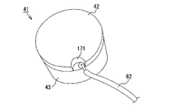
- the area of the base material 42 may be made smaller than the area of the piezoelectric element 43 by providing a notch 171 in the base material 42 (see FIG. 19).
- a first lead wire 62 (see FIGS. 3 and 19) is connected by soldering to the area exposed through the notch 171 of the front surface 51 (bonded surface to the base material 42) of the piezoelectric element 43. be done.
- the piezoelectric element 43 may be provided with 25 or more (for example, 30, 36, etc.) vibrating portions 90 via the grooves K1, or 23 or less (for example, 16, 12, etc.) vibrating portions 90 . , 10, 8, etc.) vibrating portions 90 may be arranged. Further, in each of the above embodiments, the piezoelectric element 43 has the vibrating portion 90 with the same central angle (15°), but the piezoelectric element 43 may have a plurality of types of vibrating portions with different central angles. good.
- the groove K1 is entirely void K0, but a part of the groove K1 may be filled with a filler.
- the internal region of the groove K1 may consist of a filled region filled with a filler (not shown) and a non-filled region not filled with the filler.
- a filling region is set at the outer end of each groove K1
- a non-filling region is set at a portion of each groove K1 excluding the outer end. and the positions of the non-filled regions are not particularly limited and can be changed as appropriate.
- the volume of the unfilled region may be larger than the volume of the filled region, smaller than the volume of the filled region, or equal to the volume of the filled region.
- the entire inner region of each groove K1 may be filled with a filler.
- the specific gravity of the filler is preferably 1.5 or less. By doing so, the filler becomes relatively light, so that the filler is less likely to be a load of vibration of the vibrating portion 90 . As a result, it is possible to prevent a decrease in transmission/reception sensitivity due to the filler.
- the piezoelectric element 43 of each of the above-described embodiments has a structure in which a plurality of divided vibrating portions 90 are connected to each other at the ends on the front surface 51 side.
- the piezoelectric element may have a structure in which a plurality of vibrating portions are completely divided.
- the ultrasonic transducer is configured by attaching each vibrating portion to the base material 42 respectively.
- the piezoelectric element 43 made of lead zirconate titanate (PZT) is used in the ultrasonic transducer 41 of each of the above embodiments, but the material for forming the piezoelectric element 43 is not particularly limited.
- PZT lead zirconate titanate
- the material for forming the piezoelectric element 43 is not particularly limited.
- potassium sodium niobate (alkali niobate), barium titanate, PMN-PT (Pb (Mg 1/3 Nb 2/3 )O 3 —PbTiO 3 ) single crystal, PZNT (Pb(Zn 1/3 Nb 2/3 )O 3 —PbTiO 3 ) single crystal, LiNbO 3 single crystal piezoelectric element. may be used.
- the base material 42 made of glass epoxy (FR-4) is used in the ultrasonic transducer 41 of each of the above embodiments. etc., and can be changed as appropriate.
- glass epoxy (CEM-3), polyphenyl sulfide (PPS), Duratron (registered trademark of QUADRANT group), fluorosint (registered trademark of QUADRANT group), and a substrate made of porous alumina may be used. .
- the metal foil 60 is used for electrical connection of the split back electrodes 55. Electrical connection may be made.
- the ultrasonic transducer 41 in each of the above embodiments was used in the sonar 11 that mechanically changes the irradiation direction of ultrasonic waves, but may be used in other measuring equipment.
- the ultrasonic transducer may be used in a sonar that electrically changes the irradiation direction of ultrasonic waves.
- the ultrasonic transducer may be used in a fish finder that does not change the irradiation direction of ultrasonic waves, that is, does not have the driving mechanism 30 .
- the ultrasonic transducer may be used for measuring equipment such as a probe for measuring the depth of water and an aerial sensor for measuring distance in the air.
- the depth of the groove is 0.8 times or more the maximum width of the vibrating portion in the outer peripheral direction. oscillator.
- the inner region of the groove is composed of a filled region filled with a filler and a non-filled region not filled with the filler.
Abstract
The present invention addresses the problem of providing an ultrasonic transducer for a measurement apparatus, whereby the frequency band suitable for the transmission and reception of ultrasonic waves can be widened. This ultrasonic transducer 41 for a measurement apparatus according to the present invention comprises: a substrate 42 having a substantially circular outer shape and also serving as an acoustic matching layer; and a piezoelectric element 43 having a substantially circular outer shape and joined to the substrate 42. The piezoelectric element 43 has a plurality of groove parts K1 communicating with each other in a central part 57 and extending radially, and has a plurality of substantially fan-shaped vibration parts 90 that are arranged via the groove parts K1. The piezoelectric element 43 vibrates in the thickness direction in a first frequency band and vibrates in the radial direction of the vibration part 90 in a second frequency band lower than the first frequency band.
Description
本発明は、超音波を送受信する計測機器用の超音波振動子に関するものである。
The present invention relates to an ultrasonic transducer for measuring equipment that transmits and receives ultrasonic waves.
従来、超音波の送受信によって魚群などの被探知物を検知するソナーが知られている。ソナーは、超音波を送受信する超音波振動子と、鉛直方向を向いた回転軸を中心とした旋回運動や回転軸に直交する傾動軸を中心とした傾動運動を超音波振動子に行わせる機構とを備えた計測機器である。そして、超音波振動子を運動させながら超音波の送受信を行うことにより、水中が探知できるようになっている。そして、水中を探知した探知結果は、探知画像として画面に表示される。なお、超音波振動子は、一般的に、音響整合層と、同音響整合層に接合された圧電素子とを備えている。
2. Description of the Related Art Conventionally, there has been known a sonar that detects an object to be detected such as a school of fish by transmitting and receiving ultrasonic waves. Sonar consists of an ultrasonic transducer that transmits and receives ultrasonic waves, and a mechanism that causes the ultrasonic transducer to rotate around a vertical rotation axis and tilt around a tilting axis perpendicular to the rotation axis. It is a measuring instrument with By transmitting/receiving ultrasonic waves while moving the ultrasonic transducer, underwater can be detected. Then, the result of underwater detection is displayed on the screen as a detected image. An ultrasonic transducer generally includes an acoustic matching layer and a piezoelectric element bonded to the acoustic matching layer.
ところで、ソナー用の超音波振動子は、円板状の圧電素子を用いており、超音波の周波数帯域が狭い。近年、同様のソナーを搭載した船舶が増加しているため、他の船舶との混信が生じやすくなってきている。混信を避けるためには、付近の船舶が使用している駆動周波数を外して超音波を送受信すればよいが、周波数帯域が狭い場合には、変更できる周波数の選択肢が少なくなってしまう。このため、超音波の周波数帯域が広い超音波振動子を用いることが求められている。
By the way, an ultrasonic transducer for sonar uses a disk-shaped piezoelectric element, and the frequency band of ultrasonic waves is narrow. In recent years, since the number of ships equipped with similar sonars has increased, interference with other ships is becoming more likely to occur. In order to avoid interference, it is possible to transmit and receive ultrasonic waves by removing the driving frequency used by nearby ships. Therefore, it is required to use an ultrasonic transducer with a wide ultrasonic frequency band.
なお、超音波を広帯域にする手法としては、図20,図21に示されるように、超音波振動子191を構成する圧電素子192に、同一方向に延びる複数の溝部193を形成し、溝部193を介して複数の振動部194を配設することが提案されている(例えば、特許文献1参照)。このようにすれば、各振動部194のそれぞれが圧電素子192の厚さ方向に変形しやすくなるため、圧電素子192が各部位において変形しやすくなる。その結果、圧電素子192が振動しやすくなるため、電気機械結合係数が高くなり、周波数帯域も広くなる。
20 and 21, a plurality of
ところが、特許文献1は、圧電素子192を主として厚さ方向に振動しやすくする技術であるため、超音波の送受信に適した周波数帯域が十分に得られているとは言い難い。ゆえに、超音波の周波数帯域をより広くすることが求められている。
However, since
本発明は上記の課題に鑑みてなされたものであり、その目的は、超音波の送受信に適した周波数帯域を広げることが可能な計測機器用の超音波振動子を提供することにある。
SUMMARY OF THE INVENTION The present invention has been made in view of the above problems, and an object of the present invention is to provide an ultrasonic transducer for measuring equipment capable of widening a frequency band suitable for transmitting and receiving ultrasonic waves.
上記課題を解決するために、請求項1に記載の発明は、超音波を送受信する計測機器用の超音波振動子であって、略円形状の外形を有し、音響整合層を兼ねる基材と、略円形状の外形を有し、前記基材に対して接合された前面及びその反対側にある背面を有する圧電素子とを備え、前記圧電素子には、中央部にて互いに連通しかつ放射状に延びる複数の溝部が形成されるとともに、前記溝部を介して複数の略扇状の振動部が配設され、前記圧電素子は、第1の周波数帯で厚さ方向に振動するとともに、前記第1の周波数帯よりも低い第2の周波数帯で前記振動部の半径方向に振動することを特徴とする計測機器用の超音波振動子をその要旨とする。
In order to solve the above problems, the invention according to
従って、請求項1に記載の発明によれば、圧電素子に溝部を形成することにより複数の振動部を得ているため、各振動部のそれぞれが高さ方向に変形しやすくなる。その結果、圧電素子が厚さ方向に振動しやすくなるため、電気機械結合係数が高くなり、厚さ方向振動の周波数帯である第1の周波数帯の送受感度が高くなり、第1の周波数帯の範囲も広くなる。しかも、圧電素子に放射状の溝部を形成することにより略扇状の振動部を得ているため、半径方向振動の共振周波数で駆動したときに、振動部における中央部側の端部、即ち、略円形状の超音波振動子の中央部で振幅が大きくなる。その結果、振動部の半径方向振動の周波数帯である第2の周波数帯の送受感度が高くなる。以上のことから、厚さ方向振動及び半径方向振動の双方において、高感度な送受信を行うことができる。
Therefore, according to the first aspect of the invention, since a plurality of vibrating portions are obtained by forming grooves in the piezoelectric element, each vibrating portion is easily deformed in the height direction. As a result, the piezoelectric element is more likely to vibrate in the thickness direction, resulting in a higher electromechanical coupling coefficient and a higher transmission/reception sensitivity in the first frequency band, which is the frequency band of vibration in the thickness direction. range is also widened. Moreover, since the substantially fan-shaped vibrating portion is obtained by forming the radial grooves in the piezoelectric element, when the vibrating portion is driven at the resonance frequency of the radial vibration, the end of the vibrating portion on the central side, that is, the substantially circular The amplitude becomes large at the central portion of the shaped ultrasonic transducer. As a result, the transmission/reception sensitivity of the second frequency band, which is the frequency band of radial vibration of the vibrating portion, is increased. As described above, high-sensitivity transmission and reception can be performed in both the thickness direction vibration and the radial direction vibration.
なお、「略円形状の外形を有する基材」とは、円形状の外形を有する基材だけでなく、楕円形状の外形を有する基材や、長円形状の外形を有する基材なども含むものとする。同様に、「略円形状の外形を有する圧電素子」も、円形状の外形を有する圧電素子だけでなく、楕円形状の外形を有する圧電素子や、長円形状の外形を有する圧電素子なども含むものとする。
The term "substrate having a substantially circular outer shape" includes not only a substrate having a circular outer shape, but also a substrate having an elliptical outer shape, a substrate having an oval outer shape, and the like. shall be taken. Similarly, the “piezoelectric element having a substantially circular outer shape” includes not only a piezoelectric element having a circular outer shape, but also a piezoelectric element having an elliptical outer shape, a piezoelectric element having an elliptical outer shape, and the like. shall be taken.
請求項2に記載の発明は、請求項1において、前記圧電素子は、前記中央部に貫通孔を有する略円環状をなしており、前記貫通孔の内壁面は、複数の前記振動部における前記中央部側の端面を構成していることをその要旨とする。
The invention according to claim 2 is the piezoelectric element according to
従って、請求項2に記載の発明によると、圧電素子が中央部に貫通孔を有する略円環状をなすことにより、振動部における中央部側の端部が面で構成されて尖らないようになるため、振動部の欠けを防ぐことができる。
Therefore, according to the second aspect of the invention, the piezoelectric element has a substantially annular shape with a through hole in the center, so that the end of the vibrating portion on the center side is formed of a surface and is not sharp. Therefore, chipping of the vibrating portion can be prevented.
請求項3に記載の発明は、請求項1または2において、複数の前記振動部は、第1の径方向長さを有する1つ以上の第1の振動部と、前記第1の径方向長さよりも短い第2の径方向長さを有する1つ以上の第2の振動部と、前記第1の径方向長さよりも長い第3の径方向長さを有する1つ以上の第3の振動部とを含むことをその要旨とする。
The invention according to claim 3 is based on
従って、請求項3に記載の発明では、複数の振動部が、径方向長さが異なる3種類の振動部を含んでいる。この場合、各振動部に半径方向振動が生じるものの、個々の共振周波数が異なり、当該半径方向振動が生じる周波数帯が上下に少しずつずれるため、個々の周波数帯同士が合成されることで周波数帯(第2の周波数帯)の幅が広くなる。よって、超音波の周波数帯域がよりいっそう広くなる。
Therefore, in the third aspect of the invention, the plurality of vibrating portions includes three types of vibrating portions having different radial lengths. In this case, although radial vibration occurs in each vibrating portion, the individual resonance frequencies are different, and the frequency band in which the radial vibration occurs is slightly shifted up and down. (second frequency band) becomes wider. Therefore, the frequency band of ultrasonic waves is further widened.
請求項4に記載の発明は、請求項1乃至3のいずれか1項において、前記複数の溝部同士の交点が、前記圧電素子の中心から偏心していることをその要旨とする。
The gist of the invention according to claim 4 is that in any one of
従って、請求項4に記載の発明によると、複数の溝部同士の交点が圧電素子の中心から偏心することにより、径方向長さが異なる複数種類の振動部を得ることができる。この場合、各振動部に半径方向振動が生じるものの、個々の共振周波数が異なり、当該半径方向振動が生じる周波数帯が少しずつずれるため、個々の周波数帯同士が合成されることで周波数帯(第2の周波数帯)の幅が広くなる。よって、超音波の周波数帯域がよりいっそう広くなる。また、溝部同士の交点を偏心させることにより、外形が円形状であっても、径方向長さが異なる複数種類の振動部を得ることができる。
Therefore, according to the fourth aspect of the present invention, it is possible to obtain a plurality of types of vibrating portions having different radial lengths by eccentrically displacing the intersections of the plurality of grooves from the center of the piezoelectric element. In this case, although radial vibration occurs in each vibrating part, the individual resonance frequencies are different, and the frequency band in which the radial vibration occurs is slightly shifted. 2 frequency band) becomes wider. Therefore, the frequency band of ultrasonic waves is further widened. Further, by eccentrically eccentrically intersecting the grooves, it is possible to obtain a plurality of types of vibrating portions having different radial lengths even if the outer shape is circular.
請求項5に記載の発明は、請求項4において、前記圧電素子は真円状の外形を有しており、前記交点は、前記圧電素子の外径の1%以上10%以下の長さだけ前記圧電素子の中心から偏心していることをその要旨とする。
The invention according to
従って、請求項5に記載の発明によると、複数の溝部同士の交点が、圧電素子の外径の1%以上10%以下の長さだけ圧電素子の中心から偏心することにより、径方向長さが異なる複数種類の振動部を得ることができる。この場合、各振動部に半径方向振動が生じるものの、個々の共振周波数が異なり、当該半径方向振動が生じる周波数帯が少しずつずれるため、個々の周波数帯同士が合成されることで周波数帯(第2の周波数帯)の幅が広くなる。よって、超音波の周波数帯域がよりいっそう広くなる。
Therefore, according to the fifth aspect of the invention, the intersection of the plurality of grooves is offset from the center of the piezoelectric element by a length of 1% or more and 10% or less of the outer diameter of the piezoelectric element. It is possible to obtain a plurality of types of vibrating portions with different values. In this case, although radial vibration occurs in each vibrating part, the individual resonance frequencies are different, and the frequency band in which the radial vibration occurs is slightly shifted. 2 frequency band) becomes wider. Therefore, the frequency band of ultrasonic waves is further widened.
請求項6に記載の発明は、請求項1乃至4のいずれか1項において、前記圧電素子は略楕円状の外形を有していることをその要旨とする。
According to a sixth aspect of the invention, in any one of the first to fourth aspects, the piezoelectric element has a substantially elliptical outer shape.
従って、請求項6に記載の発明によると、圧電素子が略楕円形状の外形を有することにより、複数の振動部が、径方向長さが異なる複数種類の振動部を含むようになる。この場合、各振動部に半径方向振動が生じるものの、個々の共振周波数が異なり、当該半径方向振動が生じる周波数帯が少しずつずれるため、個々の周波数帯同士が合成されることで周波数帯(第2の周波数帯)の幅が広くなる。よって、超音波の周波数帯域がよりいっそう広くなる。また、複数の溝部同士の交点を圧電素子の中心から偏心させなくても、径方向長さが異なる複数種類の振動部を得ることができる。
Therefore, according to the sixth aspect of the invention, since the piezoelectric element has a substantially elliptical outer shape, the plurality of vibrating portions include a plurality of types of vibrating portions having different lengths in the radial direction. In this case, although radial vibration occurs in each vibrating part, the individual resonance frequencies are different, and the frequency band in which the radial vibration occurs is slightly shifted. 2 frequency band) becomes wider. Therefore, the frequency band of ultrasonic waves is further widened. Moreover, it is possible to obtain a plurality of types of vibrating portions having different radial lengths without eccentrically eccentrically intersecting the intersections of the plurality of grooves from the center of the piezoelectric element.
請求項7に記載の発明は、請求項1乃至6のいずれか1項において、前記圧電素子の外径は、前記圧電素子の厚さの2倍以上であることをその要旨とする。
A seventh aspect of the invention provides the piezoelectric element according to any one of the first to sixth aspects, wherein the outer diameter of the piezoelectric element is at least twice the thickness of the piezoelectric element.
従って、請求項7に記載の発明によると、圧電素子の外径が圧電素子の厚さの2倍以上であるため、圧電素子の中央部から外周側に向けて延びる振動部が半径方向に振動しやすい細長形状となる。その結果、電気機械結合係数が確実に高くなるため、半径方向振動の周波数帯である第2の周波数帯の範囲を確実に広くすることができる。
Therefore, according to the seventh aspect of the invention, since the outer diameter of the piezoelectric element is at least twice the thickness of the piezoelectric element, the vibrating portion extending from the central portion of the piezoelectric element toward the outer peripheral side vibrates in the radial direction. It has an elongated shape that is easy to hold. As a result, the electromechanical coupling coefficient reliably increases, so that the range of the second frequency band, which is the frequency band of the radial vibration, can be reliably widened.
請求項8に記載の発明は、請求項1乃至7のいずれか1項において、前記圧電素子には、前記溝部を介して8個以上の前記振動部が配設されていることをその要旨とする。
The invention according to claim 8 is characterized in that, in any one of
従って、請求項8に記載の発明によると、圧電素子に8個以上の振動部を配設することにより、1個当りの振動部の幅が小さくなるため、各振動部のそれぞれが高さ方向に振動しやすい形状となる。つまり、圧電素子が厚さ方向に振動しやすい形状となるため、電気機械結合係数を高くすることができ、厚さ方向振動の周波数帯である第1の周波数帯の感度を高め、帯域を広くすることができる。
Therefore, according to the eighth aspect of the invention, by arranging eight or more vibrating portions in the piezoelectric element, the width of each vibrating portion becomes small, so that each vibrating portion extends in the height direction. It becomes a shape that is easy to vibrate. That is, since the piezoelectric element has a shape that easily vibrates in the thickness direction, the electromechanical coupling coefficient can be increased, the sensitivity of the first frequency band, which is the frequency band of vibration in the thickness direction, is increased, and the band is widened. can do.
以上詳述したように、請求項1~8に記載の発明によると、超音波の送受信に適した周波数帯域を広げることが可能な計測機器用の超音波振動子を得ることができる。
As described in detail above, according to the first to eighth aspects of the invention, it is possible to obtain an ultrasonic transducer for measuring equipment capable of widening the frequency band suitable for transmitting and receiving ultrasonic waves.
[第1実施形態]
以下、本発明を具体化した第1実施形態を図面に基づき詳細に説明する。
[First embodiment]
BEST MODE FOR CARRYING OUT THE INVENTION A first embodiment embodying the present invention will be described in detail below with reference to the drawings.
図1,図2に示されるように、本実施形態のソナー11は、船舶(図示略)の船底部に搭載されて使用される。ソナー11は、水中に超音波を照射することにより、水中に存在する魚群などの被探知物を探知する計測機器である。
As shown in FIGS. 1 and 2, the
また、ソナー11はソナードーム20を備えている。ソナードーム20は、ABS樹脂(アクリロニトリルブタジエンスチレン樹脂)などの樹脂材料を用いて形成されており、上ケース21、下ケース22及び蓋体23によって構成されている。上ケース21は、下端にて開口する有底円筒状のケースであり、下ケース22は、上端にて開口する有底円筒状のケースである。なお、下ケース22の下端部はドーム状(半球状)をなしている。また、蓋体23は、円板状をなし、上ケース21の下端側開口及び下ケース22の上端側開口を閉塞するためのものである。なお、蓋体23と上ケース21とによって上側収容空間24が形成されるとともに、蓋体23と下ケース22とによって下側収容空間25が形成される。
The
また、ソナードーム20には、超音波を送受信するソナー11用の超音波振動子41と、超音波振動子41を収納するケース40と、超音波振動子41を移動させる駆動機構30とが収容されている。駆動機構30は、スキャンモータ31及びチルトモータ32等を備えている。スキャンモータ31は、上側収容空間24内において蓋体23の中央部に設置されている。本実施形態のスキャンモータ31としては、ステッピングモータが用いられている。そして、スキャンモータ31の回転軸31aは、鉛直方向に沿って延びており、蓋体23の中央部に設けられた貫通孔33を挿通して下側収容空間25内に突出している。さらに、回転軸31aの先端は、円板状をなす支持板34の中央部に接続され、支持板34の下面には支持フレーム35が取り付けられている。支持フレーム35は、一対の腕部35aを有するコ字状をなしている。
Further, the
図1,図2に示されるように、ケース40は、ABS樹脂などの樹脂材料を用いて一端が開口する有底円筒状に形成されている。また、ケース40には、回転軸31aに直交する傾動軸36が設けられている。傾動軸36は、2つの傾動軸部36aに分断されており、両傾動軸部36aは、ケース40の両端部(図2では左側部及び右側部)から互いに反対方向に突出している。そして、両傾動軸部36aは、ベアリング(図示略)を介して支持フレーム35の両腕部35aに設けられた貫通孔にそれぞれ嵌め込まれている。よって、スキャンモータ31の回転軸31aが回転すると、支持板34、支持フレーム35、ケース40及び超音波振動子41は、回転軸31aを中心とした旋回運動を行う。これに伴い、超音波振動子41から出力される超音波の照射方向は、回転軸31aの周方向に沿って変化する。
As shown in FIGS. 1 and 2, the
図1,図2に示されるように、チルトモータ32は、支持フレーム35の上端部に取り付けられている。本実施形態のチルトモータ32としては、ステッピングモータが用いられている。チルトモータ32の出力軸32aは、一対の傾動軸部36aと平行に配置されており、その先端部にはピニオンギヤ32bが取り付けられている。ピニオンギヤ32bは、ケース40に取り付けられた略半円状のチルト歯車37に噛合している。よって、チルトモータ32の出力軸32aが回転すると、ピニオンギヤ32b及びチルト歯車37が回動するのに伴い、ケース40及び超音波振動子41は、傾動軸36(傾動軸部36a)を中心とした傾動運動を行う。これに伴い、超音波振動子41から出力される超音波の照射角度も、超音波振動子41の傾動に伴って変化する。
As shown in FIGS. 1 and 2, the
図3~図5に示されるように、超音波振動子41は、基材42及び圧電素子43を備えている。基材42は、略円形状の外形を有し、音響整合層を兼ねる樹脂製板状物である。そして、基材42の外周部には4つの張出部44が設けられ、各張出部44にはそれぞれネジ孔45が設けられている。各ネジ孔45は、圧電素子43(超音波振動子41)の中心O1を基準として等角度間隔で配置されている。また、各ネジ孔45には、基材42の裏面42b側の開口部に座繰り加工が施されている。よって、ネジ孔45にネジ(図示略)を挿通したとしても、ネジの頭部は基材42の裏面42bから突出しないため、ネジと超音波振動子41を収容するソナードーム20との干渉を避けることができる。
As shown in FIGS. 3 to 5, the
そして、各ネジ孔45にネジを挿通し、挿通したネジの先端部をケース40に螺着させる。その結果、超音波振動子41がケース40に固定される。なお、超音波振動子41をケース40に固定した際には、ケース40と基材42との間に隙間が生じるようになる。そして、この隙間が、ケース40内外を連通する連通口48となる。
Then, a screw is inserted through each
また、圧電素子43は、真円状の外形を有し、例えば、圧電セラミックスであるチタン酸ジルコン酸鉛(PZT)を用いて形成されたセラミックス製板状物である。図3~図5に示されるように、圧電素子43の外径D1は基材42の外径よりも小さいため、基材42の面積は圧電素子43の面積よりも大きくなる。また、圧電素子43は、基材42に対して接合された前面51と、前面51の反対側にある背面52と、前面51及び背面52に直交する外周面53とを有している。さらに、図3,図6に示されるように、圧電素子43の前面51には前面側電極54が形成され、圧電素子43の背面52には背面側電極55が形成されている。なお、本実施形態では、圧電素子43の前面51の全体が、前面側電極54及び接着層56(図6参照)を介して基材42に接合されている。また、圧電素子43は、前面側電極54及び背面側電極55の間に電圧を印加することにより、厚さ方向に分極されている。
The
図4~図7に示されるように、圧電素子43には、24本の溝部K1が形成されるとともに、溝部K1を介して24個の振動部90が配設されている。各溝部K1は、圧電素子43の中央部57にて互いに連通しかつ放射状に延びている。そして、各溝部K1は、圧電素子43の中心O1を基準として等角度間隔で配置されている。つまり、各溝部K1同士の交点は中心O1と一致している。また、各溝部K1の幅は、互いに等しくなっている。さらに、各溝部K1内には、樹脂材料(エポキシ樹脂、ウレタン樹脂、シリコーン樹脂等)や接着剤(エポキシ系接着剤等)などからなる充填材が何ら充填されていないため、各溝部K1は全体的に空隙K0となっている。
As shown in FIGS. 4 to 7, the
図4に示されるように、各振動部90は、背面視で略扇状をなしている。具体的に言うと、図7に示されるように、振動部90の表面91(背面52)は、3つの辺92,93,94によって構成されており、辺92が背面視で円弧状をなし、辺93,94が背面視で直線状をなしている。なお、各振動部90の外側面95は、圧電素子43の外周面53を構成している。
As shown in FIG. 4, each vibrating
図4~図7に示されるように、各振動部90は、圧電素子43の前面51側の端部において互いに繋がっている。また、略扇状の振動部90の半径方向長さL0は振動部90の高さH1よりも大きくなっている。なお、振動部90の高さH1は、溝部K1の深さと等しくなっている。さらに、上述した基材42の厚さは、振動部90の高さH1よりも小さくなっている。また、圧電素子43において振動部90同士が繋がる部分の厚さH2は、基材42の厚さよりも小さくなっている。さらに、本実施形態では、圧電素子43の外径D1が、圧電素子43の厚さH3の2倍以上となっている。また、溝部K1の深さは、圧電素子43の厚さH3よりも小さく、かつ、振動部90の外周方向における最大幅の0.8倍以上となっている。
As shown in FIGS. 4 to 7, the vibrating
図6に示されるように、各振動部90の表面91上には、それぞれ背面側電極55が形成されている。そして、複数の背面側電極55の各々を架け渡すようにして、略円形状の導電性部材である金属箔60(例えば、銅箔、黄銅箔、アルミニウム箔など)が貼付されている。また、金属箔60は、はんだ等の導電金属や、従来周知の導電性フィラーを含む接着剤などにより、各背面側電極55に貼付されている。なお、金属箔60の貼付により、金属箔60は、各振動部90の表面91の共通電極となる。
As shown in FIG. 6, a rear-
そして、図3に示されるように、前面側電極54には第1のリード線62が接続され、背面側電極55には第2のリード線63が接続されている。第1のリード線62は、前面側電極54から外側に延出された側面端子(図示略)に対してはんだ付けなどにより接続されている。第2のリード線63は、複数の背面側電極55のいずれか1つに対してはんだ付けなどにより接続されている。そして、第1のリード線62及び第2のリード線63は、配線チューブ64によって結束され、ケース40の上部に設けられた配線挿通孔49を通ってケース40外に引き出される。なお、第1のリード線62は側面端子に接続されているが、前面側電極54及び基材42の表面42aに銅箔等の金属箔(図示略)を貼付し、金属箔に対して第1のリード線62をはんだ付けなどにより接続してもよい。
A
また、圧電素子43の背面52側には、シート状の防音材65(バッキング材)が貼付されている。防音材65は、残響を抑えるためのものであり、ケース40の内周面にも貼付されている。なお、防音材65としては、樹脂材料やゴムに対して、金属やセラミックスからなる粒子または繊維を含有させたものや、樹脂材料に対して空孔を分散的に設けたもの(スポンジなど)を用いることができる。
A sheet-like soundproof material 65 (backing material) is attached to the
そして、図1,図2に示されるソナードーム20内には、超音波を伝搬させる超音波伝搬液体(図示略)が充填されている。また、超音波伝搬液体の一部は、ケース40に設けられた連通口48を介してケース40内に流入し、圧電素子43において隣接する振動部90間の空隙K0(溝部K1)に流入し、空隙K0を満たしている。なお、本実施形態の超音波伝搬液体は流動パラフィンである。また、上述した基材42の固有音響インピーダンスは、圧電素子43の固有音響インピーダンスよりも小さく、かつ超音波伝搬液体の固有音響インピーダンスや水の固有音響インピーダンスよりも大きくなっている。
The
次に、ソナー11を用いて被探知物を探知する方法を説明する。
Next, a method of detecting an object to be detected using the
まず、ソナー11の電源(図示略)をオンする。次に、制御装置(図示略)は、超音波振動子41に対して発振信号を出力させる制御を行い、超音波振動子41を駆動させる。このとき、圧電素子43の各振動部90は、収縮と伸長とを繰り返す。なお、振動部90が高さ方向に収縮した際には、振動部90が幅方向、具体的には、振動部90の外周側(図7の矢印f1参照)に、収縮した体積分だけ太くなるように変形する。そして、振動部90が高さ方向に伸長すると、振動部90が幅方向、具体的には、振動部90の中央部側(図7の矢印f2参照)に変形する。その結果、圧電素子43が振動し、超音波振動子41から水中に対して超音波が照射(送信)される。
First, the
そして、超音波が魚群などの被探知物(図示略)に到達すると、超音波は、被探知物で反射して反射波となり、ソナー11に向かって伝搬して超音波振動子41に入力(受信)される。その後、超音波振動子41が受信した超音波(反射波)は、受信信号に変換されて制御装置に入力される。この時点で、被探知物が探知される。
Then, when the ultrasonic waves reach an object to be detected (not shown) such as a school of fish, the ultrasonic waves are reflected by the object to be detected, become reflected waves, propagate toward the
さらに、制御装置は、スキャンモータ31を駆動させる制御を行い、回転軸31aを中心とした旋回運動を超音波振動子41に行わせる。また、制御装置は、チルトモータ32を駆動させる制御を行い、傾動軸36を中心とした傾動運動を超音波振動子41に行わせる。その結果、超音波の照射方向が徐々に変化し、これに伴って探知範囲も徐々に変化する。その後、作業者が電源をオフすると、超音波の照射及び反射波の受信が終了する。
Further, the control device performs control to drive the
次に、超音波振動子41の製造方法を説明する。
Next, a method for manufacturing the
まず、基材42を準備する。具体的には、ガラスエポキシ(FR-4)からなる樹脂製板状物を円形状に切削加工する。また、圧電素子43となるべきセラミックス製板状物を準備する。具体的には、チタン酸ジルコン酸鉛(PZT)からなる円板状のセラミックス製焼結体を作製した後、表面研磨を行うことにより、セラミックス製板状物を得る。次に、セラミックス製板状物の前面51に前面側電極54を形成するとともに、セラミックス製板状物の背面52に背面側電極55を形成する。具体的には、セラミックス製板状物の前面51及び背面52にそれぞれ銀ペーストを塗布し、塗布した銀ペーストを焼成することにより、電極54,55を形成する。そして、前面側電極54及び背面側電極55の間に電圧を印加することにより、セラミックス製板状物を厚さ方向に分極させる分極処理を行う。
First, the
次に、基材42の片面に対して、セラミックス製板状物を前面側電極54を介して接合する。具体的には、前面側電極54の表面及び基材42の表面42aのいずれか一方に対して、接着層56となる接着剤(エポキシ系接着剤など)を塗布し、基材42に対してセラミックス製板状物を接着固定する。なお、接着剤を塗布する代わりに、はんだ等を用いてロウ付けを行ってもよい。
Next, a ceramic plate is joined to one side of the
その後、切削加工等を行うことにより、セラミックス製板状物における背面52側に24本の溝部K1を形成する。その結果、セラミックス製板状物が24個の振動部90に分割されるとともに、セラミックス製板状物の背面52に形成された背面側電極55も24枚(振動部90と同数)に分割される。この時点で、圧電素子43が完成する。なお、各振動部90は、圧電素子43の前面51側の端部において互いに繋がった状態で分割されるため、前面51に形成された前面側電極54までが分割されることはない。その後、複数の背面側電極55の各々を架け渡すようにして金属箔60を貼付し、各背面側電極55を、各振動部90の表面91の共通電極とする。そして、この時点で、超音波振動子41が完成する。
After that, 24 grooves K1 are formed on the
従って、本実施形態によれば以下の効果を得ることができる。
Therefore, according to this embodiment, the following effects can be obtained.
(1)本実施形態の超音波振動子41では、圧電素子43に溝部K1を形成することにより複数の振動部90を得ているため、各振動部90のそれぞれが高さ方向に変形しやすくなる。その結果、圧電素子43が厚さ方向F1(図7参照)に振動しやすくなるため、電気機械結合係数が高くなり、厚さ方向振動の周波数帯である第1の周波数帯の送受感度が高くなり、第1の周波数帯の範囲も広くなる。しかも、圧電素子43に放射状の溝部K1を形成することにより略扇状の振動部90を得ているため、半径方向振動の共振周波数で駆動したときに、振動部90における中央部57側の端部、即ち、略円形状の超音波振動子41の中央部で振幅が大きくなる。その結果、振動部90の半径方向振動の周波数帯である第2の周波数帯の送受感度が高くなる。以上のことから、厚さ方向振動及び半径方向振動の双方において、高感度な送受信を行うことができる。
(1) In the
(2)本実施形態の圧電素子43は、第1の周波数帯で厚さ方向F1に振動するだけでなく、第1の周波数帯とは異なる周波数帯、具体的には、第1の周波数帯よりも低い第2の周波数帯で半径方向F2(図7参照)にも振動する。そこで、厚さ方向F1に振動する第1の周波数帯(例えば200kHz付近)と、半径方向F2に振動する第2の周波数帯(例えば50kHz付近)とに切り替えて超音波振動子41を駆動すれば、それぞれの周波数帯で超音波を送受信することが可能となる。また、ソナー11に1つの超音波振動子41を設けるだけで、2つの周波数帯において超音波の送受信が可能となるため、ソナー11の軽量化、小型化、低コスト化を図ることができる。
(2) The
なお、第2の周波数帯で超音波振動子41を駆動(低周波駆動)する場合には、高周波に比べて減衰しにくく深い探知が可能であって、広指向角となるという特長がある反面、受信信号(反射波)の分解能は低下する。一方、第1の周波数帯で超音波振動子41を駆動(高周波駆動)すれば、減衰が大きく探知深度は浅くなるが、高分解能で狭い指向角の探知が可能となる。このように、1つの超音波振動子41で周波数を切り替えて駆動できることから、状況に応じた探知が選択できるようになる。
When the
(3)本実施形態では、音響整合層を兼ねる基材42の面積が圧電素子43の面積よりも大きくなっているため、超音波を、基材42を介して確実に送受信させることができる。また、基材42を、ケース40の支持体としても用いることができる。
(3) In the present embodiment, since the area of the
(4)本実施形態では、圧電素子43を構成する各振動部90が、圧電素子43の前面51側の端部において互いに繋がっているため、前面51に形成された前面側電極54が分割されることはない。この場合、前面側電極54(側面端子)に第1のリード線62を接続すれば、前面側電極54全体との導通を確実に図ることができるため、ソナー11を容易に作製することができる。また、各振動部90が圧電素子43の前面51側の端部において互いに繋がることにより、圧電素子43の前面51全体が基材42の表面42aに接触する。このため、両者の接触面積が確保され、圧電素子43と基材42との接合強度が向上する。その結果、超音波振動子41の信頼性が高くなる。
(4) In the present embodiment, the vibrating
[第2実施形態]
以下、本発明を具体化した第2実施形態を図面に基づいて説明する。ここでは、前記第1実施形態と相違する部分を中心に説明する。本実施形態では、超音波振動子の構造が第1実施形態とは異なっている。
[Second embodiment]
A second embodiment embodying the present invention will be described below with reference to the drawings. Here, the description will focus on the parts that are different from the first embodiment. This embodiment differs from the first embodiment in the structure of the ultrasonic transducer.
詳述すると、図8に示されるように、本実施形態の超音波振動子41では、複数の溝部K1の中心線(図示略)同士の交点C1が、圧電素子43の中心O1から偏心している。具体的に言うと、交点C1は、圧電素子43の外径D1の1%以上10%以下の長さだけ中心O1から偏心している。このため、各溝部K1は、交点C1を中心として等角度間隔で配置されている。
More specifically, as shown in FIG. 8, in the
また、図9に示されるように、各振動部90は、半径方向長さが異なる12種類の振動部90をそれぞれ2つずつ有している。そして、本実施形態では、各振動部90のうち、半径方向長さL0が最小及び最大となるものを除いた任意の2つを選択し、これらを第1の振動部101と定義している(図9では、例えば短い方から7番目のもの)。なお、各第1の振動部101は、第1の径方向長さL1を有している。さらに、本実施形態では、各振動部90の中から、第1の径方向長さL1よりも短い第2の径方向長さL2を有する任意の2つを選択し、これらを第2の振動部102と定義している(図9では、例えば短い方から1番目(最小値)のもの)。また、本実施形態では、各振動部90の中から、第1の径方向長さL1よりも長い第3の径方向長さL3を有する任意の2つを選択し、これらを第3の振動部103と定義している(図9では、例えば短い方から12番目(最大値)のもの)。なお、各振動部101~103の径方向長さL1~L3は、振動部101~103の高さよりも大きくなっている。
In addition, as shown in FIG. 9, each vibrating
従って、本実施形態では、各溝部K1同士の交点C1が圧電素子43の中心O1から偏心しているため、各振動部90が、半径方向長さL0が異なる12種類の振動部となる。この場合、各振動部90に半径方向振動が生じるものの、個々の共振周波数が異なり、当該半径方向振動が生じる周波数帯が少しずつずれるため、個々の周波数帯同士が合成されることで周波数帯(第2の周波数帯)の幅が広くなる。よって、超音波の周波数帯域がよりいっそう広くなる。
Therefore, in this embodiment, since the intersection C1 between the grooves K1 is eccentric from the center O1 of the
[超音波振動子の評価]
以下、超音波振動子の評価方法及びその結果を説明する。
[Evaluation of Ultrasonic Vibrator]
The method of evaluating the ultrasonic transducer and the results thereof will be described below.
まず、真円状の外形を有する圧電素子の一部である扇状の振動部を準備した。具体的には、中心角は等しいものの、半径及び厚さが異なる2つの振動部を作製し、これらをサンプルA,Bとした。
First, a fan-shaped vibrating portion, which is a part of a piezoelectric element having a perfectly circular outer shape, was prepared. Specifically, two vibrating parts having the same center angle but different radii and thicknesses were produced, and these were used as samples A and B. As shown in FIG.
次に、サンプルA,Bに対して、振動部のインピーダンスを測定した。具体的には、各測定用サンプルにおいて、インピーダンスアナライザを用いて30kHz~300kHzの間で周波数をスイープし、インピーダンスを測定した。
Next, for samples A and B, the impedance of the vibrating portion was measured. Specifically, in each measurement sample, an impedance analyzer was used to sweep the frequency between 30 kHz and 300 kHz to measure the impedance.
その結果、サンプルAでは、振動部の半径方向振動の共振領域(谷になっている領域)が70kHz付近にあり、振動部の厚さ方向振動の共振領域が200kHz付近にあることが確認された(図10参照)。一方、サンプルAよりも半径及び厚さが大きいサンプルBでは、振動部の半径方向振動の共振領域が50kHz付近にあり、振動部の厚さ方向振動の共振領域が160kHz付近にあることが確認された(図11参照)。従って、サンプルA,Bのいずれにおいても、これらの振動部は、厚さ方向に振動する際の周波数よりも低い周波数で半径方向に振動することが確認された。また、半径方向振動での変位量は、両端部(中心部及び外周部)に行くに従って大きくなり、厚さ方向振動での変位量は、中間部の表面側及び裏面側に行くに従って大きくなることが確認された。さらに、サンプルAよりも振動部の半径が大きいサンプルBでは、半径方向振動の周波数のピーク(共振領域)がサンプルAよりも低いことが確認された。また、サンプルAよりも振動部の厚さが厚いサンプルBでは、厚さ方向振動の周波数のピーク(共振領域)がサンプルBよりも低いことも確認された。なお、サンプルA,Bは、いずれも同様の波形を有することが確認された。
As a result, in sample A, it was confirmed that the resonance region (valley region) of the vibration in the radial direction of the vibrating portion was around 70 kHz, and the resonance region of the vibration in the thickness direction of the vibrating portion was around 200 kHz. (See FIG. 10). On the other hand, in sample B, which has a larger radius and thickness than sample A, it was confirmed that the resonance region of the vibration in the radial direction of the vibrating portion was around 50 kHz, and the resonance region of the vibration in the thickness direction of the vibrating portion was around 160 kHz. (see FIG. 11). Therefore, in both samples A and B, it was confirmed that these vibrating portions vibrate in the radial direction at a frequency lower than the frequency when vibrating in the thickness direction. In addition, the amount of displacement in the radial direction vibration increases toward both ends (the central portion and the outer peripheral portion), and the amount of displacement in the thickness direction vibration increases toward the front surface side and the back surface side of the intermediate portion. was confirmed. Furthermore, it was confirmed that the frequency peak (resonance region) of the radial vibration in sample B, which has a larger radius of the vibrating portion than in sample A, is lower than in sample A. It was also confirmed that sample B, which has a vibrating portion thicker than sample A, has a lower frequency peak (resonance region) of the vibration in the thickness direction. It was confirmed that samples A and B both have similar waveforms.
次に、圧電素子と基材とからなる超音波振動子を準備した。詳述すると、真円状の外形を有する圧電素子122に対して放射状に延びる溝部123を形成することにより、扇状の振動部124が形成された超音波振動子121(即ち、第1実施形態の超音波振動子41と同様の超音波振動子)を作製し、これを実施例1とした(図12(a)参照)。具体的には、外径50mm、厚さ7.2mmの圧電素子122を、外径54mm、厚さ3.6mmの基材125(ガラスエポキシ板)に接着し、24本の溝部123を15°のピッチで等角度間隔に形成した。
Next, an ultrasonic transducer composed of a piezoelectric element and a base material was prepared. More specifically, an
また、真円状の外形を有する圧電素子132に対して放射状に延びる溝部133を形成し、かつ溝部133同士の交点を圧電素子132の中心から偏心させることにより、扇状の振動部134が形成された超音波振動子131(即ち、第2実施形態の超音波振動子41と同様の超音波振動子)を作製し、これを実施例2とした(図12(b)参照)。具体的には、外径50mm、厚さ7.2mmの圧電素子132を、外径54mm、厚さ3mmの基材135(ガラスエポキシ板)に接着し、24本の溝部133を15°のピッチで等角度間隔に形成した。また、溝部133同士の交点を、5mm(即ち、圧電素子132の外径の10%)だけ圧電素子132の中心から偏心させた。
A fan-shaped vibrating
一方、真円状の外形を有する圧電素子142に対して一方向に延びる溝部143を複数形成することにより、複数の帯状の振動部144が形成された超音波振動子141を作製し、これを比較例とした(図12(c)参照)。具体的には、外径50mm、厚さ7.2mmの圧電素子142を、外径54mm、厚さ3.6mmの基材145に接着し、12本の溝部143を等間隔かつ平行に形成した。
On the other hand, by forming a plurality of
次に、実施例1,2及び比較例に対して、超音波振動子121,131,141のインピーダンスを測定した。具体的には、各測定用サンプルにおいて、インピーダンスアナライザを用いて30kHz~300kHzの間で周波数をスイープし、インピーダンスを測定した。
Next, the impedances of the
その結果、実施例1では、超音波振動子121の半径方向振動の共振領域が80kHz付近にあり、超音波振動子121の厚さ方向振動の共振領域が170kHz付近にあることが確認された(図13(a)参照)。また、実施例2では、超音波振動子131の半径方向振動の共振領域が70kHz付近にあり、超音波振動子131の厚さ方向振動の共振領域が170kHz付近にあることが確認された(図13(b)参照)。一方、比較例では、超音波振動子141の半径方向振動の共振領域が30kHz付近にあり、超音波振動子141の厚さ方向振動の共振領域が180kHz付近にあることが確認された(図13(c)参照)。
As a result, in Example 1, it was confirmed that the resonance region of the vibration in the radial direction of the
以上のことから、実施例1,2及び比較例の超音波振動子121,131,141は、いずれも厚さ方向振動の周波数よりも低い周波数で半径方向に振動することが確認された。また、厚さ方向振動では、実施例1,2及び比較例2の全てにおいて、周波数及びインピーダンスが同等であることが確認された。一方、半径方向振動では、比較例の周波数が実施例1,2の周波数よりも低く、かつ比較例のインピーダンスが実施例1,2のインピーダンスよりも高いことが確認された。従って、圧電素子142に対して一方向に延びる溝部143を形成した超音波振動子141(比較例)は、厚さ方向振動の周波数が超音波の送受信に適しているものの、半径方向振動の周波数は、超音波の送受信には適さないことが確認された。
From the above, it was confirmed that the
次に、以下の測定用サンプルを試作した。真円状の外形を有する圧電素子に対して放射状に延びる溝部を形成することにより、扇状の振動部が形成された超音波振動子(即ち、第1実施形態の超音波振動子41と同様の超音波振動子)を試作し、これをサンプル1(図14参照)とした。そして、サンプル1の超音波振動子に対して、各振動部の表面上にある電極の各々を架け渡すようにして略円形状の金属箔をはんだ付けし、これをケースに収容した。
Next, the following samples for measurement were fabricated. An ultrasonic transducer having a fan-shaped vibrating portion (that is, similar to the
また、真円状の外形を有する圧電素子に対して放射状に延びる溝部を形成し、かつ溝部同士の交点を圧電素子の中心から3mm(ここでは、圧電素子の外径の6%)だけ偏心させることにより、扇状の振動部が形成された超音波振動子(即ち、第2実施形態の超音波振動子41と同様の超音波振動子)を試作し、これをサンプル2(図14参照)とした。そして、サンプル2の超音波振動子に対して、各振動部の表面上にある電極の各々を架け渡すようにして略円形状の金属箔をはんだ付けし、これをケースに収容した。
Further, grooves extending radially are formed in the piezoelectric element having a perfect circular outer shape, and the intersection of the grooves is offset from the center of the piezoelectric element by 3 mm (here, 6% of the outer diameter of the piezoelectric element). As a result, an ultrasonic vibrator having a fan-shaped vibrating portion (that is, an ultrasonic vibrator similar to the
さらに、真円状の外形を有する圧電素子に対して一方向に延びる溝部を複数形成することにより、複数の帯状の振動部が形成された超音波振動子を試作し、これをサンプル3(図14参照)とした。具体的には、まず、圧電素子を基材に接着し、複数の溝部を等間隔かつ平行に形成した。そして、各振動部の表面上にある電極の各々を架け渡すようにして、帯状の金属箔をはんだ付けし、これをケースに収容した。
Furthermore, by forming a plurality of grooves extending in one direction on a circular piezoelectric element, an ultrasonic transducer having a plurality of band-shaped vibrating portions was fabricated. 14). Specifically, first, a piezoelectric element was adhered to a substrate, and a plurality of grooves were formed at equal intervals in parallel. Then, strip-shaped metal foil was soldered so as to span the electrodes on the surface of each vibrating portion, and this was housed in a case.
また、真円状の外形を有する圧電素子に溝部が形成されていない超音波振動子を試作し、これをサンプル4(図14参照)とした。具体的には、まず、圧電素子を基材に接着した。そして、圧電素子の背面上にある電極に対して配線を施し、これをケースに収容した。
In addition, an ultrasonic transducer having no groove formed in a piezoelectric element having a perfectly circular outer shape was experimentally produced, and this was designated as sample 4 (see FIG. 14). Specifically, first, the piezoelectric element was adhered to the substrate. Then, wiring was applied to the electrodes on the back surface of the piezoelectric element, and this was housed in a case.
次に、各測定用サンプル(サンプル1~4)に対して、超音波振動子の送受感度を算出した。具体的には、超音波振動子の放射面を水中に浸漬し、放射面から170mm離れた位置にあるSUS板に対して超音波を垂直に照射した。そして、SUS板で反射した超音波(反射波)は、超音波振動子で受信され、超音波振動子の両端に電圧信号を生じる。このとき、超音波振動子の送信時及び受信時の電圧振幅をオシロスコープにより測定し、送信電圧波形及び受信電圧波形の双方の周波数成分解析と演算とを行うことにより、送受感度を算出した。なお、送受感度は、送信電圧の振幅Vsに対する受信電圧の振幅Vrの比であり、20×log(Vr/Vs) の式から算出されるものである。また、図14のグラフは、サンプル1~4における周波数と送受感度との関係を示している。
Next, the transmission/reception sensitivity of the ultrasonic transducer was calculated for each measurement sample (
その結果、真円状の外形を有する圧電素子に対して放射状に延びる溝部を形成したサンプル1では、圧電素子が、210kHzで送受感度がピークとなる第1の周波数帯で厚さ方向に振動するとともに、第1の周波数帯よりも低く、80kHzで送受感度がピークとなる第2の周波数帯で振動部の半径方向に振動することが確認された。そして、送受感度が例えば-33dB以上となる範囲は、第1の周波数帯で135kHz~325kHz付近となり、第2の周波数帯で80kHz~90kHz付近となることが確認された。以上のことから、サンプル1は、第1の周波数帯及び第2の周波数の両方が、超音波の送受信に適していることが確認された。また、溝部を放射状に形成すると、200kHz付近で広帯域となる一方、80kHz付近では狭帯域となる超音波振動子となることが確認された。
As a result, in the
また、真円状の外形を有する圧電素子に対して放射状に延びる溝部を形成し、かつ溝部同士の交点を圧電素子の中心から偏心させたサンプル2では、圧電素子が、220kHzで送受感度がピークとなる第1の周波数帯で厚さ方向に振動するとともに、90kHzで送受感度がピークとなる第2の周波数帯で振動部の半径方向に振動することが確認された。そして、送受感度が例えば-33dB以上となる範囲は、第1の周波数帯で140kHz~325kHz付近となり、第2の周波数帯で80kHz~90kHz付近となることが確認された。以上のことから、サンプル2は、サンプル1と同様に、第1の周波数帯及び第2の周波数帯の両方が、超音波の送受信に適していることが確認された。
Further, in Sample 2, in which grooves extending radially are formed in a piezoelectric element having a perfectly circular outer shape and the intersections of the grooves are eccentric from the center of the piezoelectric element, the piezoelectric element has a peak transmission/reception sensitivity at 220 kHz. It was confirmed that the first frequency band vibrates in the thickness direction and the radial direction of the vibrating portion vibrates in the second frequency band in which the transmission/reception sensitivity peaks at 90 kHz. It has been confirmed that the range in which the transmission/reception sensitivity is -33 dB or more, for example, is around 140 kHz to 325 kHz in the first frequency band and around 80 kHz to 90 kHz in the second frequency band. From the above, it was confirmed that both the first frequency band and the second frequency band of sample 2 are suitable for transmission and reception of ultrasonic waves, like
一方、真円状の外形を有する圧電素子に対して一方向に延びる溝部を形成したサンプル3では、圧電素子が、220kHzで送受感度がピークとなる周波数帯で厚さ方向に振動することが確認された。そして、送受感度が例えば-33dB以上となる範囲は、220kHzをピークとする周波数帯で140kHz~340kHz付近となることが確認された。なお、サンプル3では、半径方向振動のピークは認められなかった。以上のように、比較例であるサンプル3では、厚さ方向振動で広帯域となっているものの、切込み(溝部)の長手方向振動による送受感度が弱いことが確認された。それに対して、実施例であるサンプル1,2では、サンプル3と同様の厚さ方向の送受感度と帯域特性を持つことに加えて、振動部の半径方向振動による低周波での送受信も可能となることが確認された。
On the other hand, in Sample 3, in which grooves extending in one direction were formed in the piezoelectric element having a perfect circular shape, it was confirmed that the piezoelectric element vibrated in the thickness direction in the frequency band where the transmission/reception sensitivity peaked at 220 kHz. was done. It was confirmed that the range in which the transmission/reception sensitivity is -33 dB or more, for example, is around 140 kHz to 340 kHz in a frequency band with a peak of 220 kHz. In sample 3, no radial vibration peak was observed. As described above, it was confirmed that Sample 3, which is a comparative example, has a wide band in thickness direction vibration, but weak transmission/reception sensitivity due to longitudinal direction vibration of the notch (groove). On the other hand, in
また、真円状の外形を有する圧電素子に対して何ら溝部が形成されていないサンプル4では、圧電素子が、205kHzで送受感度がピークとなる周波数帯で厚さ方向に振動するとともに、50kHzで送受感度がピークとなる周波数帯で径方向(直径方向)に振動することが確認された。そして、送受感度が例えば-33dB以上となる範囲は、第1の周波数帯で195kHz~230kHz付近となり、第2の周波数帯で45kHz~55kHz付近となることが確認された。比較例としたサンプル4は、50kHzと200kHzとの2周波切替タイプの魚群探知機用振動子として、広く市場に浸透しているものである。一方、実施例であるサンプル1,2は、200kHz付近の厚さ方向振動がサンプル4よりも高感度かつ広帯域であることに加えて、低周波の径方向振動の送受感度もサンプル4と同等の感度が得られており、サンプル4と同様に両周波数帯で使用することが可能である。
In sample 4, in which no grooves were formed in the piezoelectric element having a perfect circular outer shape, the piezoelectric element vibrated in the thickness direction in the frequency band where the transmission/reception sensitivity peaked at 205 kHz, and at 50 kHz. It was confirmed that there was vibration in the radial direction (diameter direction) in the frequency band where the transmission/reception sensitivity peaked. It was also confirmed that the range in which the transmission/reception sensitivity is -33 dB or more, for example, is around 195 kHz to 230 kHz in the first frequency band and around 45 kHz to 55 kHz in the second frequency band. Sample 4 used as a comparative example is widely used in the market as a two-frequency switching type fish finder vibrator of 50 kHz and 200 kHz. On the other hand,
なお、上記実施形態を以下のように変更してもよい。
In addition, you may change the said embodiment as follows.
・図15に示されるように、圧電素子43は、中央部57に円形状の貫通孔151を有する略円環状をなしており、貫通孔151の内壁面は、各振動部90における中央部57側の端面152を構成していてもよい。このようにすれば、振動部90における中央部57側の端部が面で構成されて尖らないようになるため、振動部90の欠けを防ぐことができる。また、貫通孔151を設けることにより、圧電素子43を構成するセラミックスの体積が減少するため、材料費の削減にもなる。なお、貫通孔151の内径は、例えば、圧電素子43の外径D1の1%以上20%以下の長さであることが好ましい。
As shown in FIG. 15, the
さらに、図16の超音波振動子41に示されるように、圧電素子43が貫通孔151を有する略円環状をなすのに加えて、基材42も、中央部57に円形状の貫通孔153を有する略円環状をなしていてもよい。なお、貫通孔153は、配線作業等のやり易さを考慮して、超音波の送受信を妨げない程度の大きさに形成される。
Furthermore, as shown in the
・上記各実施形態の超音波振動子41は、真円状の外形を有する圧電素子43を備えていたが、圧電素子は、楕円状の外形を有する圧電素子43(図17(a)参照)であってもよいし、長円状の外形を有する圧電素子43(図17(b)参照)であってもよい。
The
・図18に示されるように、圧電素子43は、中央部57に楕円形状の貫通孔161を有する略円環状をなしていてもよいし、中央部57に長円形状の貫通孔(図示略)を有する略円環状をなしていてもよい。即ち、貫通孔は、真円でない形状(矩形など)であってもよい。これらのようにすれば、各振動部90が、半径方向長さが異なる複数種類の振動部90を含むようになる。この場合、各振動部90に半径方向振動が生じるものの、個々の共振周波数が異なり、当該半径方向振動が生じる周波数帯が少しずつずれるため、個々の周波数帯同士が構成されることで周波数帯(第2の周波数帯)の幅が広くなる。よって、超音波の周波数帯域がよりいっそう広くなる。
- As shown in FIG. 18, the
・上記各実施形態では、基材42の面積が圧電素子43の面積よりも大きくなっていた。しかし、基材42の面積は、圧電素子43の面積と等しくてもよい。また、例えば、基材42に切り欠き171を設ける等することにより(図19参照)、基材42の面積を圧電素子43の面積よりも小さくしてもよい。なお、圧電素子43の前面51(基材42との接着面)のうち切り欠き171を介して露出する領域には、第1のリード線62(図3,図19参照)がはんだ付けにより接続される。
- In each of the above-described embodiments, the area of the
・上記各実施形態の圧電素子43には、溝部K1を介して24個の振動部90(中心角15°)が配設されていた。しかし、圧電素子43には、溝部K1を介して25個以上(例えば、30個,36個等)の振動部90が配設されていてもよいし、23個以下(例えば、16個,12個,10個,8個等)の振動部90が配設されていてもよい。また、上記各実施形態では、圧電素子43が同じ中心角(15°)の振動部90を有していたが、圧電素子43は、中心角が異なる複数種類の振動部を有していてもよい。
- Twenty-four vibrating portions 90 (with a central angle of 15°) are arranged in the
・上記各実施形態の超音波振動子41では、溝部K1が全体的に空隙K0となっていたが、溝部K1の一部に充填材が充填されていてもよい。例えば、それぞれの溝部K1について、溝部K1の内部領域が、充填材(図示略)が充填される充填領域と、充填材が充填されない非充填領域とからなっていてもよい。具体的に言うと、各溝部K1の外周側の端部に充填領域が設定され、各溝部K1において外周側の端部を除く部分に非充填領域が設定されることが考えられるが、充填領域及び非充填領域の位置は、特に限定される訳ではなく、適宜変更可能である。また、非充填領域の体積は、充填領域の体積よりも大きくてもよいし、充填領域の体積より小さくてもよいし、充填領域の体積と等しくてもよい。また、各溝部K1の内部領域の全体に充填材が充填されていてもよい。
- In the
なお、充填材の比重は1.5以下であることが好ましい。このようにすれば、充填材が比較的軽くなるため、充填材が振動部90の振動の負荷になりにくくなる。その結果、充填材に起因する送受感度の低下を防止することができる。
The specific gravity of the filler is preferably 1.5 or less. By doing so, the filler becomes relatively light, so that the filler is less likely to be a load of vibration of the vibrating
・上記各実施形態の圧電素子43は、分割された複数の振動部90が前面51側の端部において互いに繋がった構造を有していた。しかし、圧電素子は、複数の振動部が完全に分割された構造を有していてもよい。この場合、各振動部を基材42に対してそれぞれ貼付することにより、超音波振動子が構成される。
- The
・上記各実施形態の超音波振動子41では、チタン酸ジルコン酸鉛(PZT)からなる圧電素子43を用いたが、圧電素子43の形成材料は特に限定されるものではない。例えば、ニオブ酸カリウムナトリウム系(ニオブ酸アルカリ系)、チタン酸バリウム系、PMN-PT(Pb(Mg
1/3Nb2/3)O3-PbTiO3)単結晶、PZNT(Pb(Zn1/3Nb2/3)O3-PbTiO3)単結晶、LiNbO3単結晶の圧電セラミックスからなる圧電素子を用いてもよい。
The
1/3 Nb 2/3 )O 3 —PbTiO 3 ) single crystal, PZNT (Pb(Zn 1/3 Nb 2/3 )O 3 —PbTiO 3 ) single crystal, LiNbO 3 single crystal piezoelectric element. may be used.
・上記各実施形態の超音波振動子41では、ガラスエポキシ(FR-4)からなる基材42を用いたが、基材42の形成材料は、固有音響インピーダンス、超音波の周波数、機械的強度等を考慮して適宜変更することができる。例えば、ガラスエポキシ(CEM-3)、ポリフェニルサルファイド(PPS)、ジュラトロン(QUADRANTグループの登録商標)、フルオロシント(QUADRANTグループの登録商標)、アルミナの多孔体からなる基材を用いてもよい。
The base material 42 made of glass epoxy (FR-4) is used in the ultrasonic transducer 41 of each of the above embodiments. etc., and can be changed as appropriate. For example, glass epoxy (CEM-3), polyphenyl sulfide (PPS), Duratron (registered trademark of QUADRANT group), fluorosint (registered trademark of QUADRANT group), and a substrate made of porous alumina may be used. .
・上記各実施形態の超音波振動子41では、分割した背面側電極55の電気的接続に金属箔60が用いられていたが、銅線などの線材のはんだ付けにより、分割した背面側電極55の電気的接続を行ってもよい。
In the ultrasonic transducer 41 of each of the above-described embodiments, the metal foil 60 is used for electrical connection of the split back electrodes 55. electrical connection may be made.
・上記各実施形態の超音波振動子41は、超音波の照射方向を機械的に変更するソナー11に用いられていたが、他の計測機器に用いられていてもよい。例えば、超音波振動子を、超音波の照射方向を電気的に変更するソナーに用いてもよい。また、超音波振動子を、超音波の照射方向を変更しない、即ち、駆動機構30を有しない魚群探知機に用いてもよい。さらに、超音波振動子を、例えば、水の深さを計測する測探機や、空気中で距離を計測する空中センサなどの計測機器に用いてもよい。
· The ultrasonic transducer 41 in each of the above embodiments was used in the sonar 11 that mechanically changes the irradiation direction of ultrasonic waves, but may be used in other measuring equipment. For example, the ultrasonic transducer may be used in a sonar that electrically changes the irradiation direction of ultrasonic waves. Further, the ultrasonic transducer may be used in a fish finder that does not change the irradiation direction of ultrasonic waves, that is, does not have the driving mechanism 30 . Further, the ultrasonic transducer may be used for measuring equipment such as a probe for measuring the depth of water and an aerial sensor for measuring distance in the air.
次に、特許請求の範囲に記載された技術的思想のほかに、前述した実施形態によって把握される技術的思想を以下に列挙する。
Next, in addition to the technical ideas described in the claims, technical ideas grasped by the above-described embodiments are listed below.
(1)請求項1乃至8のいずれか1項において、前記基材の面積は前記圧電素子の面積よりも大きいことを特徴とする計測機器用の超音波振動子。
(1) An ultrasonic transducer for measuring equipment according to any one of claims 1 to 8, characterized in that the area of the base material is larger than the area of the piezoelectric element.
(2)請求項1乃至8のいずれか1項において、前記基材の面積は前記圧電素子の面積と等しいことを特徴とする計測機器用の超音波振動子。
(2) An ultrasonic transducer for measuring equipment according to any one of claims 1 to 8, characterized in that the area of the base material is equal to the area of the piezoelectric element.
(3)請求項1乃至8のいずれか1項において、前記基材の面積は前記圧電素子の面積よりも小さいことを特徴とする計測機器用の超音波振動子。
(3) An ultrasonic transducer for measuring equipment according to any one of claims 1 to 8, characterized in that the area of the base material is smaller than the area of the piezoelectric element.
(4)請求項1乃至8のいずれか1項において、複数の前記振動部が、前記圧電素子の前記前面側の端部において互いに繋がっていることを特徴とする計測機器用の超音波振動子。
(4) An ultrasonic transducer for measuring equipment according to any one of claims 1 to 8, characterized in that a plurality of said vibrating parts are connected to each other at said front end of said piezoelectric element. .
(5)請求項1乃至8のいずれか1項において、前記溝部の深さは前記圧電素子の厚さよりも小さいことを特徴とする計測機器用の超音波振動子。
(5) The ultrasonic transducer for measuring equipment according to any one of claims 1 to 8, wherein the depth of the groove is smaller than the thickness of the piezoelectric element.
(6)請求項1乃至8のいずれか1項において、前記溝部の深さは、前記振動部の外周方向における最大幅の0.8倍以上であることを特徴とする計測機器用の超音波振動子。
(6) In any one of claims 1 to 8, the depth of the groove is 0.8 times or more the maximum width of the vibrating portion in the outer peripheral direction. oscillator.
(7)請求項1乃至8のいずれか1項において、前記溝部が全体的に空隙となっていることを特徴とする計測機器用の超音波振動子。
(7) The ultrasonic vibrator for measuring equipment according to any one of claims 1 to 8, characterized in that the groove is entirely void.
(8)請求項1乃至8のいずれか1項において、1本の前記溝部について、前記溝部の内部領域が、充填材が充填される充填領域と、前記充填材が充填されない非充填領域とからなることを特徴とする計測機器用の超音波振動子。
(8) In any one of claims 1 to 8, in one groove, the inner region of the groove is composed of a filled region filled with a filler and a non-filled region not filled with the filler. An ultrasonic transducer for measuring equipment, characterized by:
(9)請求項1乃至8のいずれか1項において、前記溝部の内部領域の全体に充填材が充填されていることを特徴とする計測機器用の超音波振動子。
(9) The ultrasonic transducer for measuring equipment according to any one of claims 1 to 8, characterized in that the entire inner region of the groove is filled with a filler.
(10)請求項1乃至8のいずれか1項において、前記充填材の比重が1.5以下であることを特徴とする計測機器用の超音波振動子。
(10) The ultrasonic transducer for measuring equipment according to any one of claims 1 to 8, wherein the filler has a specific gravity of 1.5 or less.
11…計測機器としてのソナー
41…超音波振動子
42…基材
43…圧電素子
51…圧電素子の前面
52…圧電素子の背面
57…圧電素子の中央部
90…振動部
101…第1の振動部
102…第2の振動部
103…第3の振動部
151,161…貫通孔
152…振動部における中央部側の端面
C1…複数の溝部同士の交点
D1…圧電素子の外径
F1…厚さ方向
F2…半径方向
H3…圧電素子の厚さ
K1…溝部
L1…第1の径方向長さ
L2…第2の径方向長さ
L3…第3の径方向長さ
O1…圧電素子の中心 REFERENCE SIGNS LIST 11:Sonar 41 as measuring instrument 41: Ultrasonic oscillator 42: Base material 43: Piezoelectric element 51: Front surface of piezoelectric element 52: Back surface of piezoelectric element 57: Central part of piezoelectric element 90: Vibrating part 101: First vibration Part 102 Second vibrating part 103 Third vibrating part 151, 161 Through hole 152 Central side end face C1 of vibrating part Intersection point D1 of a plurality of grooves Outer diameter F1 of piezoelectric element Thickness Direction F2 Radial direction H3 Piezoelectric element thickness K1 Groove L1 First radial length L2 Second radial length L3 Third radial length O1 Center of piezoelectric element
41…超音波振動子
42…基材
43…圧電素子
51…圧電素子の前面
52…圧電素子の背面
57…圧電素子の中央部
90…振動部
101…第1の振動部
102…第2の振動部
103…第3の振動部
151,161…貫通孔
152…振動部における中央部側の端面
C1…複数の溝部同士の交点
D1…圧電素子の外径
F1…厚さ方向
F2…半径方向
H3…圧電素子の厚さ
K1…溝部
L1…第1の径方向長さ
L2…第2の径方向長さ
L3…第3の径方向長さ
O1…圧電素子の中心 REFERENCE SIGNS LIST 11:
Claims (8)
- 超音波を送受信する計測機器用の超音波振動子であって、
略円形状の外形を有し、音響整合層を兼ねる基材と、略円形状の外形を有し、前記基材に対して接合された前面及びその反対側にある背面を有する圧電素子とを備え、
前記圧電素子には、中央部にて互いに連通しかつ放射状に延びる複数の溝部が形成されるとともに、前記溝部を介して複数の略扇状の振動部が配設され、
前記圧電素子は、第1の周波数帯で厚さ方向に振動するとともに、前記第1の周波数帯よりも低い第2の周波数帯で前記振動部の半径方向に振動する
ことを特徴とする計測機器用の超音波振動子。 An ultrasonic transducer for measuring equipment that transmits and receives ultrasonic waves,
A substrate having a substantially circular outer shape and serving also as an acoustic matching layer, and a piezoelectric element having a substantially circular outer shape and having a front surface joined to the base material and a back surface on the opposite side thereof. prepared,
The piezoelectric element is formed with a plurality of grooves communicating with each other and extending radially at a central portion thereof, and a plurality of substantially fan-shaped vibrating portions are disposed through the grooves,
A measuring instrument, wherein the piezoelectric element vibrates in a thickness direction in a first frequency band and vibrates in a radial direction of the vibrating portion in a second frequency band lower than the first frequency band. ultrasonic transducer for - 前記圧電素子は、前記中央部に貫通孔を有する略円環状をなしており、前記貫通孔の内壁面は、複数の前記振動部における前記中央部側の端面を構成していることを特徴とする請求項1に記載の計測機器用の超音波振動子。 The piezoelectric element has a substantially annular shape having a through hole in the central portion, and an inner wall surface of the through hole constitutes an end surface of the plurality of vibrating portions on the central portion side. The ultrasonic transducer for measuring equipment according to claim 1.
- 複数の前記振動部は、
第1の径方向長さを有する1つ以上の第1の振動部と、
前記第1の径方向長さよりも短い第2の径方向長さを有する1つ以上の第2の振動部と、
前記第1の径方向長さよりも長い第3の径方向長さを有する1つ以上の第3の振動部と
を含むことを特徴とする請求項1または2に記載の計測機器用の超音波振動子。 The plurality of vibrating parts are
one or more first vibrating portions having a first radial length;
one or more second vibrating portions having a second radial length shorter than the first radial length;
and one or more third vibrating portions having a third radial length that is longer than the first radial length. oscillator. - 前記複数の溝部同士の交点が、前記圧電素子の中心から偏心していることを特徴とする請求項1乃至3のいずれか1項に記載の計測機器用の超音波振動子。 The ultrasonic transducer for measuring equipment according to any one of claims 1 to 3, characterized in that the intersections of the plurality of grooves are eccentric from the center of the piezoelectric element.
- 前記圧電素子は真円状の外形を有しており、
前記交点は、前記圧電素子の外径の1%以上10%以下の長さだけ前記圧電素子の中心から偏心している
ことを特徴とする請求項4に記載の計測機器用の超音波振動子。 The piezoelectric element has a perfect circular outer shape,
5. The ultrasonic transducer for measuring equipment according to claim 4, wherein the intersection point is eccentric from the center of the piezoelectric element by a length of 1% or more and 10% or less of the outer diameter of the piezoelectric element. - 前記圧電素子は略楕円状の外形を有していることを特徴とする請求項1乃至4のいずれか1項に記載の計測機器用の超音波振動子。 The ultrasonic transducer for measuring equipment according to any one of claims 1 to 4, characterized in that said piezoelectric element has a substantially elliptical outer shape.
- 前記圧電素子の外径は、前記圧電素子の厚さの2倍以上であることを特徴とする請求項1乃至6のいずれか1項に記載の計測機器用の超音波振動子。 The ultrasonic transducer for measuring equipment according to any one of claims 1 to 6, characterized in that the outer diameter of the piezoelectric element is at least twice the thickness of the piezoelectric element.
- 前記圧電素子には、前記溝部を介して8個以上の前記振動部が配設されていることを特徴とする請求項1乃至7のいずれか1項に記載の計測機器用の超音波振動子。 8. The ultrasonic transducer for measuring equipment according to claim 1, wherein eight or more of said vibrating portions are arranged in said piezoelectric element via said groove portions. .
Priority Applications (2)
| Application Number | Priority Date | Filing Date | Title |
|---|---|---|---|
| JP2021526772A JP7294701B2 (en) | 2021-02-16 | 2021-02-16 | Ultrasonic transducer for measuring equipment |
| PCT/JP2021/005621 WO2022176002A1 (en) | 2021-02-16 | 2021-02-16 | Ultrasonic transducer for measurement apparatus |
Applications Claiming Priority (1)
| Application Number | Priority Date | Filing Date | Title |
|---|---|---|---|
| PCT/JP2021/005621 WO2022176002A1 (en) | 2021-02-16 | 2021-02-16 | Ultrasonic transducer for measurement apparatus |
Publications (1)
| Publication Number | Publication Date |
|---|---|
| WO2022176002A1 true WO2022176002A1 (en) | 2022-08-25 |
Family
ID=82931243
Family Applications (1)
| Application Number | Title | Priority Date | Filing Date |
|---|---|---|---|
| PCT/JP2021/005621 WO2022176002A1 (en) | 2021-02-16 | 2021-02-16 | Ultrasonic transducer for measurement apparatus |
Country Status (2)
| Country | Link |
|---|---|
| JP (1) | JP7294701B2 (en) |
| WO (1) | WO2022176002A1 (en) |
Citations (5)
| Publication number | Priority date | Publication date | Assignee | Title |
|---|---|---|---|---|
| JPH03112540A (en) * | 1989-09-28 | 1991-05-14 | Shimadzu Corp | Ultrasonic probe |
| JPH0865792A (en) * | 1994-08-25 | 1996-03-08 | Hitachi Ltd | Ultrasonic transducer, manufacture of composite piezoelectric material and the composite piezoelectric material |
| WO2012011256A1 (en) * | 2010-07-23 | 2012-01-26 | 日本電気株式会社 | Vibration device and electronic device |
| JP2019114958A (en) * | 2017-12-25 | 2019-07-11 | 第一精工株式会社 | Electro-acoustic transducer |
| JP6828944B1 (en) * | 2020-04-14 | 2021-02-10 | 本多電子株式会社 | Ultrasonic oscillator for measuring equipment |
Family Cites Families (1)
| Publication number | Priority date | Publication date | Assignee | Title |
|---|---|---|---|---|
| JP7261429B2 (en) | 2019-02-28 | 2023-04-20 | 本多電子株式会社 | Sonar, ultrasonic transducer and manufacturing method thereof |
-
2021
- 2021-02-16 WO PCT/JP2021/005621 patent/WO2022176002A1/en active Application Filing
- 2021-02-16 JP JP2021526772A patent/JP7294701B2/en active Active
Patent Citations (5)
| Publication number | Priority date | Publication date | Assignee | Title |
|---|---|---|---|---|
| JPH03112540A (en) * | 1989-09-28 | 1991-05-14 | Shimadzu Corp | Ultrasonic probe |
| JPH0865792A (en) * | 1994-08-25 | 1996-03-08 | Hitachi Ltd | Ultrasonic transducer, manufacture of composite piezoelectric material and the composite piezoelectric material |
| WO2012011256A1 (en) * | 2010-07-23 | 2012-01-26 | 日本電気株式会社 | Vibration device and electronic device |
| JP2019114958A (en) * | 2017-12-25 | 2019-07-11 | 第一精工株式会社 | Electro-acoustic transducer |
| JP6828944B1 (en) * | 2020-04-14 | 2021-02-10 | 本多電子株式会社 | Ultrasonic oscillator for measuring equipment |
Also Published As
| Publication number | Publication date |
|---|---|
| JP7294701B2 (en) | 2023-06-20 |
| JPWO2022176002A1 (en) | 2022-08-25 |
Similar Documents
| Publication | Publication Date | Title |
|---|---|---|
| Wong et al. | Development of a 20-MHz wide-bandwidth PMN-PT single crystal phased-array ultrasound transducer | |
| WO2021210055A1 (en) | Ultrasonic vibrator for measurement instrument | |
| EP2076061B1 (en) | Ultrasonic transducer | |
| KR20190073572A (en) | Ultrasonic transducer | |
| JP6732274B1 (en) | Sonar, ultrasonic transducer | |
| CN111624611B (en) | Sonar, ultrasonic vibrator and manufacturing method thereof | |
| JP7294701B2 (en) | Ultrasonic transducer for measuring equipment | |
| WO2021176726A1 (en) | Sonar | |
| US7388317B2 (en) | Ultrasonic transmitting/receiving device and method for fabricating the same | |
| JP6991613B2 (en) | Ultrasonic wave transmitter / receiver | |
| WO2021220377A1 (en) | Sonar | |
| US11965994B2 (en) | Ultrasonic transducer for a measuring device | |
| WO2021210151A1 (en) | Sonar | |
| JP5417633B2 (en) | Ultrasonic sensor | |
| JP2020155900A (en) | Sonar, ultrasonic transducer, and production method therefor | |
| JP7422377B1 (en) | Ultrasonic transducer | |
| JP7139545B1 (en) | ultrasonic transducer | |
| JPS6093899A (en) | Ultrasonic wave probe | |
| JP2023116033A (en) | piezoelectric transducer | |
| WO2023095829A1 (en) | Ultrasonic transducer | |
| JP2023116037A (en) | piezoelectric transducer | |
| JP2023116035A (en) | piezoelectric transducer | |
| JPS5944051B2 (en) | ultrasonic probe | |
| CN115699809A (en) | Ultrasonic sensor | |
| JPH07265308A (en) | Ultrasonic probe |
Legal Events
| Date | Code | Title | Description |
|---|---|---|---|
| ENP | Entry into the national phase |
Ref document number: 2021526772 Country of ref document: JP Kind code of ref document: A |
|
| 121 | Ep: the epo has been informed by wipo that ep was designated in this application |
Ref document number: 21926442 Country of ref document: EP Kind code of ref document: A1 |
|
| NENP | Non-entry into the national phase |
Ref country code: DE |
|
| 122 | Ep: pct application non-entry in european phase |
Ref document number: 21926442 Country of ref document: EP Kind code of ref document: A1 |