WO2022168188A1 - 超音波トランスデューサー及びその製造方法 - Google Patents
超音波トランスデューサー及びその製造方法 Download PDFInfo
- Publication number
- WO2022168188A1 WO2022168188A1 PCT/JP2021/003816 JP2021003816W WO2022168188A1 WO 2022168188 A1 WO2022168188 A1 WO 2022168188A1 JP 2021003816 W JP2021003816 W JP 2021003816W WO 2022168188 A1 WO2022168188 A1 WO 2022168188A1
- Authority
- WO
- WIPO (PCT)
- Prior art keywords
- plate
- piezoelectric element
- ultrasonic transducer
- support plate
- recesses
- Prior art date
- Legal status (The legal status is an assumption and is not a legal conclusion. Google has not performed a legal analysis and makes no representation as to the accuracy of the status listed.)
- Ceased
Links
Images










Classifications
-
- B—PERFORMING OPERATIONS; TRANSPORTING
- B06—GENERATING OR TRANSMITTING MECHANICAL VIBRATIONS IN GENERAL
- B06B—METHODS OR APPARATUS FOR GENERATING OR TRANSMITTING MECHANICAL VIBRATIONS OF INFRASONIC, SONIC, OR ULTRASONIC FREQUENCY, e.g. FOR PERFORMING MECHANICAL WORK IN GENERAL
- B06B1/00—Methods or apparatus for generating mechanical vibrations of infrasonic, sonic, or ultrasonic frequency
- B06B1/02—Methods or apparatus for generating mechanical vibrations of infrasonic, sonic, or ultrasonic frequency making use of electrical energy
- B06B1/06—Methods or apparatus for generating mechanical vibrations of infrasonic, sonic, or ultrasonic frequency making use of electrical energy operating with piezoelectric effect or with electrostriction
- B06B1/0607—Methods or apparatus for generating mechanical vibrations of infrasonic, sonic, or ultrasonic frequency making use of electrical energy operating with piezoelectric effect or with electrostriction using multiple elements
- B06B1/0622—Methods or apparatus for generating mechanical vibrations of infrasonic, sonic, or ultrasonic frequency making use of electrical energy operating with piezoelectric effect or with electrostriction using multiple elements on one surface
- B06B1/0629—Square array
-
- H—ELECTRICITY
- H04—ELECTRIC COMMUNICATION TECHNIQUE
- H04R—LOUDSPEAKERS, MICROPHONES, GRAMOPHONE PICK-UPS OR LIKE ACOUSTIC ELECTROMECHANICAL TRANSDUCERS; ELECTRIC HEARING AIDS; PUBLIC ADDRESS SYSTEMS
- H04R17/00—Piezoelectric transducers; Electrostrictive transducers
-
- H—ELECTRICITY
- H04—ELECTRIC COMMUNICATION TECHNIQUE
- H04R—LOUDSPEAKERS, MICROPHONES, GRAMOPHONE PICK-UPS OR LIKE ACOUSTIC ELECTROMECHANICAL TRANSDUCERS; ELECTRIC HEARING AIDS; PUBLIC ADDRESS SYSTEMS
- H04R29/00—Monitoring arrangements; Testing arrangements
-
- H—ELECTRICITY
- H10—SEMICONDUCTOR DEVICES; ELECTRIC SOLID-STATE DEVICES NOT OTHERWISE PROVIDED FOR
- H10N—ELECTRIC SOLID-STATE DEVICES NOT OTHERWISE PROVIDED FOR
- H10N30/00—Piezoelectric or electrostrictive devices
- H10N30/01—Manufacture or treatment
- H10N30/03—Assembling devices that include piezoelectric or electrostrictive parts
-
- H—ELECTRICITY
- H10—SEMICONDUCTOR DEVICES; ELECTRIC SOLID-STATE DEVICES NOT OTHERWISE PROVIDED FOR
- H10N—ELECTRIC SOLID-STATE DEVICES NOT OTHERWISE PROVIDED FOR
- H10N30/00—Piezoelectric or electrostrictive devices
- H10N30/01—Manufacture or treatment
- H10N30/06—Forming electrodes or interconnections, e.g. leads or terminals
- H10N30/063—Forming interconnections, e.g. connection electrodes of multilayered piezoelectric or electrostrictive parts
-
- H—ELECTRICITY
- H10—SEMICONDUCTOR DEVICES; ELECTRIC SOLID-STATE DEVICES NOT OTHERWISE PROVIDED FOR
- H10N—ELECTRIC SOLID-STATE DEVICES NOT OTHERWISE PROVIDED FOR
- H10N30/00—Piezoelectric or electrostrictive devices
- H10N30/80—Constructional details
- H10N30/87—Electrodes or interconnections, e.g. leads or terminals
- H10N30/875—Further connection or lead arrangements, e.g. flexible wiring boards, terminal pins
-
- H—ELECTRICITY
- H10—SEMICONDUCTOR DEVICES; ELECTRIC SOLID-STATE DEVICES NOT OTHERWISE PROVIDED FOR
- H10N—ELECTRIC SOLID-STATE DEVICES NOT OTHERWISE PROVIDED FOR
- H10N30/00—Piezoelectric or electrostrictive devices
- H10N30/80—Constructional details
- H10N30/88—Mounts; Supports; Enclosures; Casings
- H10N30/883—Additional insulation means preventing electrical, physical or chemical damage, e.g. protective coatings
-
- H—ELECTRICITY
- H10—SEMICONDUCTOR DEVICES; ELECTRIC SOLID-STATE DEVICES NOT OTHERWISE PROVIDED FOR
- H10N—ELECTRIC SOLID-STATE DEVICES NOT OTHERWISE PROVIDED FOR
- H10N39/00—Integrated devices, or assemblies of multiple devices, comprising at least one piezoelectric, electrostrictive or magnetostrictive element covered by groups H10N30/00 – H10N35/00
Definitions
- the present invention relates to an ultrasonic transducer that has a plurality of piezoelectric elements arranged in parallel and that can be suitably used as a phased array sensor, and a method for manufacturing the same.
- An ultrasonic transducer in which multiple vibrating bodies, including piezoelectric elements and diaphragms, are arranged in parallel, is suitable for use as a phased array sensor for detecting the shape of an object or for detecting the presence or absence of an object over a wide range. It is possible, but in this case the ultrasonic transducer is required to:
- the arrangement pitch of the plurality of vibrating bodies should be 1/2 or less of the wavelength ⁇ of the ultrasonic waves radiated by the vibrating bodies.
- the frequency of the ultrasonic waves emitted by the vibrating body used in the ultrasonic transducer is set to a low frequency of about 30 to 50 kHz.
- an ultrasonic transducer comprising a rigid elastic plate such as a metal plate and a plurality of piezoelectric elements fixed to the elastic plate in parallel, wherein the elastic plate is: a plurality of vibration regions in which the plurality of piezoelectric elements are mounted respectively; a plurality of restraint regions surrounding the plurality of vibration regions through low-rigidity regions such as grooves; and a boundary region that separates the outer region located radially outward, and the boundary region includes a slit portion that divides the one restraint region and the outer region, and the one restraint region.
- a patent for an invention relating to an ultrasonic transducer provided with a bridge portion that is mechanically connected to the outer region (see Patent Document 1 below).
- the presence of the low-rigidity region weakens the rigidity of the vibration region to improve the vibration characteristics of the vibrating body including the piezoelectric element and the vibration region. is useful in that the vibration in one vibration region can be effectively prevented from propagating to another vibration region, but there is room for improvement in the following points.
- the rigidity of the vibration region in the rigid elastic plate can be weakened by providing the low-rigidity region
- the piezoelectric element can be stretched and contracted against the rigidity of the vibration region to which the piezoelectric element is mounted.
- the vibrating body is caused to resonate. Theoretically, it is possible to secure the necessary amount of amplitude by
- the applicant of the present application has proposed a rigid elastic plate such as a metal plate having a plurality of openings formed in parallel, a flexible resin film provided so as to cover the entire surface of the rigid elastic plate,
- An invention relating to an ultrasonic transducer provided with a plurality of piezoelectric elements fixed to the upper surface of the flexible resin film so as to overlap with the plurality of openings in plan view has been filed and patented. (See Patent Document 2 below).
- the resonance frequency of the vibrating body including the piezoelectric element is set to 70 kHz to 80 kHz, which is higher than 40 kHz, which is the frequency of the driving voltage to be applied to the piezoelectric element. It is useful in that it is possible to obtain a high radiated sound pressure by vibrating the vibrating body with a sufficient amount of amplitude. We have discovered that it can be difficult to radiate sound waves in certain directions.
- the present invention has been made in view of such prior art, and is capable of obtaining sufficiently high radiated sound pressure even if the resonance frequency of a vibrating body including a piezoelectric element is higher than the driving frequency of the vibrating body, Another object of the present invention is to provide an ultrasonic transducer capable of maintaining a good sound pressure of sound waves emitted by a plurality of vibrating bodies even when the number of the vibrating bodies is increased, and a method of manufacturing the same.
- the present invention provides a rigid support plate having a first surface on one side in the thickness direction and a second surface on the other side in the thickness direction, wherein a plurality of recesses are opened in the first surface. and a first end portion on one end side having an opening width smaller than the opening width of the recess portion is opened to the bottom surface of the recess portion, and a second end portion on the other end side is opened to the second surface to radiate sound waves.
- a rigid support plate provided with a plurality of waveguides forming openings; a flexible resin film fixed to a first surface of the support plate so as to cover the plurality of recesses; piezoelectric elements of the same number as the plurality of recesses fixed to the first surface of the flexible resin film so that the corresponding recesses overlap and the peripheral region overlaps with the first surface of the support plate;
- the frequency of the lowest-order resonance mode of flexural vibration is higher than the drive frequency of the piezoelectric element
- the support plate is the entire ultrasonic transducer.
- an ultrasonic transducer configured so that the frequency of the lowest-order resonance mode of flexural vibration is higher than the driving frequency of the piezoelectric element.
- the ultrasonic transducer of the present invention it is possible to obtain a sufficiently high radiated sound pressure even if the resonance frequency of the vibrating body including the piezoelectric element is higher than the driving frequency of the vibrating body. Even if the number of vibrating bodies is increased, the sound pressure of the sound waves emitted by the plurality of vibrating bodies can be well maintained.
- the arrangement pitch of the piezoelectric elements is 4.3 mm or less.
- the piezoelectric element has a rectangular shape with a maximum vertical and horizontal dimension of 4.0 mm or less in plan view, a circular shape with a diameter of 4.0 mm or less in plan view, or an ellipse with a major axis of 4.0 mm or less in plan view.
- the recess has a shape similar to that of the piezoelectric element in plan view so that the overlapping width of the peripheral region of the piezoelectric element and the support plate in plan view is 0.05 mm to 0.1 mm.
- the recess has a depth of 0.05 mm to 0.15 mm.
- At least the portion of the support plate in which the plurality of waveguides are formed in the thickness direction is made of ceramics.
- the support plate includes a first plate in which a plurality of through holes having the same opening width as that of each of the plurality of recesses and a plurality of through holes having the same opening width as that of each of the plurality of waveguides are formed. and a second plate having a plurality of through holes formed therein, and the first and second plates are fixed in a layered state in the thickness direction. More preferably, the second plate is made of ceramics.
- the waveguide includes a cylindrical portion including the first end opened on the bottom surface of the recess, and the second end opened on the second surface of the support plate. and a horn portion including The tubular portion has an opening width smaller than that of the concave portion and the same opening width over the entire thickness direction. It is configured such that the width of the opening increases as it approaches the sound wave emitting opening opened in the second surface.
- the opening width of the tubular portion has a ratio of 0.15 to 0.2 with respect to the wavelength of the sound wave radiated by the vibrating body.
- the length of the tubular portion has a ratio of 0.09 or less, more preferably 0.035 or less, to the wavelength of the sound wave radiated by the vibrating body.
- the opening width of the sound wave emitting port is preferably 0.8 to 0.95 with respect to the arrangement pitch of the piezoelectric elements.
- the ultrasonic transducer according to the present invention further includes a lower sealing plate having a plurality of piezoelectric element openings each having a size surrounding the plurality of piezoelectric elements and having a thickness greater than that of the piezoelectric elements. a lower sealing plate fixed to the flexible resin film so that the plurality of piezoelectric elements are positioned within the plurality of piezoelectric element openings in plan view; and a lower sealing plate fixed to the lower sealing plate. and a wiring assembly.
- the wiring assembly includes an insulating base layer, a conductor layer provided on the base layer and including first and second wirings respectively connected to a pair of first and second electrodes of the piezoelectric element, and the conductor. and an insulating cover layer surrounding the base layer, the base layer having first wire/piezoelectric element connection openings for connecting the first wires to corresponding first electrodes of the piezoelectric elements. and a second wiring/piezoelectric element connection opening for connecting the second wiring to the corresponding second electrode of the piezoelectric element.
- the ultrasonic transducer according to the present invention may further include an upper sealing plate fixed to the lower sealing plate and the wiring assembly via flexible resin.
- the upper sealing plate has openings at positions corresponding to the plurality of piezoelectric elements.
- the ultrasonic transducer according to the present invention may further include a sound absorbing material fixed to the upper sealing plate so as to cover the plurality of openings of the upper sealing plate.
- the ultrasonic transducer according to the present invention may further include a reinforcing plate fixed to the sound absorbing material.
- a plurality of recesses opened on a first surface on one side in the thickness direction and a first end portion on one end side having an opening width smaller than the opening width of the recesses are opened on the bottom surface of the recesses.
- the vibrating body includes the same number of piezoelectric elements as the plurality of recesses fixed to the first surface of the flexible resin film, and the vibrating body formed by the piezoelectric elements and the flexible resin film operates in the lowest-order resonance mode of flexural vibration. is higher than the drive frequency of the piezoelectric element, and the support plate is arranged so that the frequency of the lowest-order resonance mode of flexural vibration of the entire ultrasonic transducer is higher than the drive frequency of the piezoelectric element.
- a method of manufacturing an ultrasonic transducer comprising: a support plate forming step of forming the support plate; a flexible resin film fixing step of fixing the plurality of piezoelectric elements to a plate; a piezoelectric element fixing step of fixing the film to the film with an insulating adhesive; and a lower side sealing having a plurality of piezoelectric element openings each having a size surrounding the plurality of piezoelectric elements and having a thickness larger than that of the piezoelectric elements.
- a lower sealing plate is prepared, and the lower sealing plate is fixed to the flexible resin film with an adhesive so that the plurality of piezoelectric elements are positioned within the plurality of piezoelectric element openings in a plan view.
- a plate installation step an insulating base layer, a conductor layer provided on the base layer and including first and second wirings respectively connected to a pair of first and second electrodes of the piezoelectric element, and the conductor layer and the base layer has a first wire/piezoelectric element connection opening and a second wire/piezoelectric element connection opening exposing portions of the first and second wires, respectively.
- a wiring assembly preparing step of preparing the provided wiring assembly a wiring assembly fixing step of fixing the base layer to the lower sealing plate with an adhesive; and the first wiring/piezoelectric element of the first wiring.
- the ultrasonic transducer can be manufactured efficiently.
- the support plate forming step forms a recess-side plate having a plate thickness equal to the depth of the plurality of recesses and having a plurality of through holes having the same opening width as each of the plurality of recesses.
- the process of forming the waveguide-side plate includes forming a plurality of through holes having the same mold depth as the length of the plurality of waveguides and the same opening width as each of the plurality of waveguides.
- a ceramic material is injected into a mold for a waveguide-side plate provided with a structure for sintering.
- the process for forming the recess side plate includes forming a through hole having the same mold depth as the depth of the plurality of recesses and the same opening width as each of the plurality of recesses.
- a ceramic material is injected into the recess-side plate mold provided with the structure and fired.
- the process of forming the recess side plate includes preparing a metal plate having the same plate thickness as the depth of the recess, and etching the metal plate to form the same opening as each of the plurality of recesses. It is configured to form a plurality of width through holes.
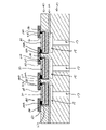
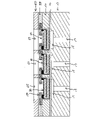
- FIG. 1 is a partial vertical cross-sectional view of an ultrasonic transducer according to Embodiment 1 of the present invention.
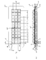
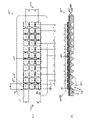
- 2 is a plan view of the piezoelectric assembly (support plate, flexible resin film and a plurality of piezoelectric elements) in the ultrasonic transducer according to Embodiment 1.
- FIG. FIG. 3 is a plan view of the support plate.
- FIG. 4 is a partial vertical cross-sectional view of an ultrasonic transducer according to a modification of the first embodiment.
- FIG. 5(a) is a plan view of the piezoelectric element
- FIG. 5(b) is a cross-sectional view taken along line VV in FIG. 5(a).
- FIG. 6(a) is a plan view of a model (piezoelectric assembly) used for the finite element method (FEM) analysis performed for the first embodiment
- FIG. 6(b) is a plan view of FIG. ) along the line VI-VI.
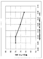
- FIG. 7 shows the thickness L2 of the portion (second plate) where the waveguide is formed and the lowest resonance frequency of the bending vibration of the entire model in the model shown in FIGS. is a graph showing the results of a finite element method analysis performed on the relationship of FIG. 8 is a finite element method performed on the relationship between the opening width D2 of the waveguide and the sound pressure level of the sound wave emitted by the vibrating body including the piezoelectric element in the model shown in FIGS.
- FIG. 9 shows the relationship between the plate thickness L1 of the recessed portion (first plate) and the sound pressure level of the sound wave radiated by the vibrating body in the model shown in FIGS. It is a graph which shows the result of the finite element method analysis which was performed.
- FIG. 10(a) is a plan view of another model (piezoelectric assembly) used in the finite element method (FEM) analysis performed for the first embodiment
- FIG. 10(b) is a plan view of FIG. It is a cross-sectional view along line X-X in (a).
- FIG. 11 shows, in the model shown in FIGS.
- FIG. 10(a) and 10(b), the thickness L2 of the portion (second plate) where the waveguide is formed and the lowest resonance frequency of the bending vibration of the entire model. is a graph showing the results of a finite element method analysis performed on the relationship of 12 is a cross-sectional view taken along line XII-XII in FIG. 1.
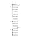
- FIG. 13 is a cross-sectional view of a support plate formed by a support plate forming step in the method of manufacturing an ultrasonic transducer according to Embodiment 1.
- FIG. 14(a) and 14(b) are cross-sectional views of a recess-side plate and a waveguide-side plate, respectively, formed by a support plate forming step in the method of manufacturing an ultrasonic transducer according to a modification of Embodiment 1; is.
- FIG. 15 shows an ultrasonic transducer support according to a modification of the first embodiment, which is formed by fixing the concave-side plate and the waveguide-side plate shown in FIGS. 14(a) and (b). It is a cross-sectional view of a plate.
- FIG. 16 is a cross-sectional view showing a state after the flexible resin film fixing step in the manufacturing method.
- FIG. 15 shows an ultrasonic transducer support according to a modification of the first embodiment, which is formed by fixing the concave-side plate and the waveguide-side plate shown in FIGS. 14(a) and (b). It is a cross-sectional view of a plate.
- FIG. 16 is a cross-sectional view
- FIG. 17 is a cross-sectional view showing the state after the piezoelectric element fixing step in the manufacturing method.
- FIG. 18 is a cross-sectional view showing the state after the step of installing the lower sealing plate in the manufacturing method.
- FIG. 19 is a cross-sectional view showing the state after the electrical connection step in the manufacturing method.
- FIG. 20 is a cross-sectional view showing the state after the upper sealing plate installation step in the manufacturing method.
- FIG. 21 is a cross-sectional view showing a state after the sound absorbing material installation step in the manufacturing method.
- FIG. 22 is a cross-sectional view showing a state after the reinforcing plate installation step in the manufacturing method.
- FIG. 23 is a partial vertical cross-sectional view of an ultrasonic transducer according to Embodiment 2 of the present invention.
- 24 is a plan view of a piezoelectric assembly (a support plate, a flexible resin film, and a plurality of piezoelectric elements) in the ultrasonic transducer according to Embodiment 2.
- FIG. FIG. 25 is a partial vertical cross-sectional view of an ultrasonic transducer according to a modification of the embodiment.
- FIG. 26(a) is a plan view of a model (piezoelectric assembly) used for the finite element method (FEM) analysis performed for the second embodiment
- FIG. 26(b) is a plan view of FIG. ) along the line XXVI-XXVI.
- FIG. 27 is an enlarged view of the XXVII portion in FIG. 26(b).
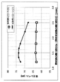
- FIG. 28 is a finite element analysis performed on the relationship between the opening width D2a of the cylindrical portion of the waveguide and the sound pressure level of the sound wave emitted by the vibrating body in the model shown in FIGS. 26(a) and (b). It is a graph which shows the result of.
- FIG. 29 is a graph showing the results of a finite element method analysis performed on the relationship between the length L2a of the cylindrical portion and the sound pressure level in the model shown in FIGS. 26(a) and (b).
- FIG. 30 is a graph showing the results of a finite element method analysis performed on the relationship between the radiation aperture D2b and the sound pressure level in the model shown in FIGS. 26(a) and 26(b).
- FIG. 1 shows a partial longitudinal sectional view of an ultrasonic transducer 1A according to this embodiment.
- the ultrasonic transducer 1 includes, as main constituent members, a rigid support plate 10 having a first surface 11 on one side in the thickness direction and a second surface 12 on the other side in the thickness direction, and a first surface 21 on one side in the thickness direction. and a second surface 22 on the other side in the thickness direction, the second surface 22 being fixed to the first surface 11 of the support plate 10; and a plurality of piezoelectric elements 30 affixed to the surface 21 .
- FIG. 2 shows the support plate 10, the flexible resin film 20 fixed to the first surface 11 of the support plate 10, and the plurality of the flexible resin films 20 fixed to the first surface 21 of the flexible resin film 20.
- the waveguide 17 has a tubular shape with an opening width smaller than that of the recess 15 and the same opening width throughout the thickness direction.
- the support plate 10 can be made of various rigid members, and can be made of a metal such as stainless steel, or preferably a ceramic material such as SiC or Al2O3, which has a lower density and a higher Young's modulus than metal. can.
- the support plate 10 is a single unit integrally including a portion in which the plurality of recesses 15 are formed and a portion in which the plurality of waveguides 17 are formed.
- the invention is not so limited.
- FIG. 4 shows a partial longitudinal sectional view of an ultrasonic transducer 1B according to a modification of this embodiment.
- the ultrasonic transducer 1B differs from the ultrasonic transducer 1A only in that the support plate 10 is changed to a support plate 100.
- FIG. 4 shows a partial longitudinal sectional view of an ultrasonic transducer 1B according to a modification of this embodiment.
- the ultrasonic transducer 1B differs from the ultrasonic transducer 1A only in that the support plate 10 is changed to a support plate 100.
- the support plate 100 includes a first plate 110 in which the plurality of recesses 15 are formed, and a second plate 120 that is separate from the first plate 110 and has a large plate thickness, It has a second plate 120 on which the plurality of waveguides 17 are formed, and the first and second plates 110 and 120 are fixed in a layered state in the thickness direction.
- the surface of the first plate 110 opposite to the second plate 120 forms the first surface 101 on one side in the thickness direction of the support plate 100, and
- the surface of the second plate 120 opposite to the first plate 110 forms the second surface 102 of the support plate 100 on the other side in the thickness direction.
- the support plate 100 has a plurality of recess through holes formed in the first plate 110 and having the same opening width as that of the plurality of recesses 15 , and a plurality of waveguides 17 in the second plate 120 . It can be easily formed by forming a plurality of waveguide through-holes having the same opening width as the opening width, and then fixing the first and second plate bodies 110 and 120 in a state of being laminated in the thickness direction. obtain.
- the first and second plates 110 and 120 can also be formed of various rigid members such as metals such as stainless steel and ceramics materials such as SiC and Al2O3.
- the second plate 120 can preferably be made of a ceramic material such as SiC or Al2O3, which has a lower density and a higher Young's modulus than metal.
- the flexible resin film 20 is fixed to the first surface 11 (101) of the support plate 10 (100) so as to cover the recesses 15.
- the flexible resin film 20 is formed of an insulating resin such as polyimide having a thickness of 20 ⁇ m to 100 ⁇ m, for example.
- the flexible resin film 20 is fixed to the support plate 10 (100) by various methods such as adhesive or thermocompression bonding.
- the piezoelectric element 30 has a central region 30C overlapping with the corresponding concave portion 15 and a peripheral region 30P overlapping with the first surface 11 (101) of the support plate 10 (100) in plan view. It is fixed to the first surface 21 of the flexible resin film 20 as shown.
- FIG. 5(a) shows a plan view of the piezoelectric element 30. As shown in FIG. Further, FIG. 5(b) shows a cross-sectional view taken along line VV in FIG. 5(a).
- the piezoelectric element 30 has a piezoelectric element main body 32 and a pair of first and second electrodes, and is configured to expand and contract when a voltage is applied between the first and second electrodes.
- the piezoelectric element 30 is of a laminated type. Compared to a single-layer piezoelectric element, the laminated piezoelectric element can increase the electric field strength when the same voltage is applied, and can increase the expansion/contraction displacement per applied voltage.
- the piezoelectric element 30 is of a two-layer laminated type.
- the piezoelectric element 30 includes the piezoelectric element main body 32 formed of a piezoelectric material such as lead zirconate titanate (PZT), a first piezoelectric portion 32a on the upper side of the piezoelectric element main body 32 in the thickness direction, and a piezoelectric element 32b.
- An inner electrode 34 partitioning the lower second piezoelectric portion 32b, an upper surface electrode 36 fixed to a portion of the upper surface of the first piezoelectric portion 32a, and a lower surface electrode fixed to the lower surface of the second piezoelectric portion 32b.
- an inner electrode terminal 34T one end of which is electrically connected to the inner electrode 34 and the other end of which is insulated from the top electrode 36 and which is accessible on the top surface of the first piezoelectric portion 32a.
- An electrode connection member 35 one end of which is electrically connected to the lower electrode 37 and the other end of which is insulated from the upper electrode 36 and the inner electrode 34, is accessible on the upper surface of the first piezoelectric portion 32a.
- a bottom electrode connection member 38 forming a bottom electrode terminal 37T.
- the outer electrode formed by the upper electrode 36 and the lower electrode 37 acts as one of the first and second electrodes
- the inner electrode 34 acts as the other of the first and second electrodes
- the polarization directions of the first and second piezoelectric portions 32a and 32b are the same with respect to the thickness direction.
- electric fields in opposite directions are applied to the first and second piezoelectric portions 32a and 32b.
- the top electrode 36 and the bottom electrode 37 are insulated from each other, so that when the piezoelectric element 30 is fabricated, a voltage is applied between the top electrode 36 and the bottom electrode 37. By doing so, the polarization directions of the first and second piezoelectric portions 32a and 32b can be made the same.
- the piezoelectric element 30 and the flexible resin film 20 act as a vibrating body that generates ultrasonic waves. is higher than the frequency of the voltage applied to the piezoelectric element 30 (driving frequency).
- a phased array in which a plurality of piezoelectric elements 30 forming a vibrating body are arranged in parallel is used to detect an object several meters away. Therefore, it is necessary to precisely control the phases of sound waves radiated from a plurality of vibrating bodies each having a plurality of piezoelectric elements 30 mounted thereon.
- the piezoelectric elements are expanded and contracted against the rigidity of the rigid support plate. It is necessary to flexibly vibrate the vibrating body formed by the piezoelectric element and the rigid support plate with a predetermined amplitude to ensure the magnitude of the generated sound pressure.
- the frequency (driving frequency) of the voltage applied to the piezoelectric element it is necessary to set the frequency (driving frequency) of the voltage applied to the piezoelectric element to the vicinity of the resonance frequency of the bending vibration of the vibrating body on which the piezoelectric element is mounted.
- the frequency response of the flexural vibration of the vibrating body on which the piezoelectric element is mounted with respect to the voltage applied to the piezoelectric element varies greatly in the vicinity of the resonance frequency of the vibrating body.
- the ultrasonic transducer 1A (1B) has a plurality of recesses 15 opened in the first surface 11 (101) and the opening width of the recesses 15 is wider than the opening width of the recesses 15.
- the rigid support plate provided with a plurality of waveguides 17 each of which has a narrowed first end opening to the bottom surface of the recess 15 and a second end opening to the second surface 12 (102).
- 10 (100) and the flexible resin film 20 fixed to the first surface 11 (101) of the support plate 10 (100) so as to cover the plurality of recesses 15 correspond to the central region 30C in plan view.
- the plurality of grooves fixed to the first surface 21 of the flexible resin film 20 so as to overlap with the concave portion 15 and the peripheral region 30P overlap with the first surface 11 (101) of the support plate 10 (100). and a piezoelectric element 30 .
- the resonance frequency of the plurality of vibrating bodies is higher than the driving frequency of the piezoelectric element 30, even if there is "variation" in the resonance frequency among the plurality of vibrating bodies, the vibration of the plurality of vibrating bodies No significant difference occurs in the phase of the frequency response of the flexural vibration. Therefore, it is possible to precisely control the phases of the sound waves generated by the plurality of vibrating bodies.
- the frequency should be a low frequency of about 30 to 50 kHz.
- the resonance frequency of the vibrating body is set to a resonance frequency (for example, 70 kHz) sufficiently higher than the driving frequency (30 to 50 kHz) of the piezoelectric element 30, it is better to increase the vertical and horizontal dimensions of the piezoelectric element 30 in plan view. , the sound pressure of the ultrasonic waves generated by the vibrator can be increased.
- the plurality of piezoelectric elements 30 are mounted respectively.
- the arrangement pitch of the plurality of piezoelectric elements 30 is set to 1/2 or less of the wavelength ⁇ of the ultrasonic waves radiated by the piezoelectric elements 30.
- the plurality of piezoelectric elements 30 are arranged in order to suppress the generation of grating lobes while setting the frequency of the ultrasonic waves radiated by the piezoelectric elements 30 to 40 kHz.
- the vertical and horizontal dimensions of the piezoelectric element 30 in plan view are preferably 3.0 mm or more from the viewpoint of ensuring sound pressure, and 4.0 mm or less from the viewpoint of suppressing the generation of grating lobes.
- the piezoelectric element 30 has a square shape in plan view.
- a rectangular shape including the following rectangles, a circular shape with a diameter of 4.0 mm or less, or an elliptical shape with a major axis of 4.0 mm or less is also possible.
- the opening width of the recess 15 is such that the frequency of the lowest-order resonance mode of the bending vibration of the vibrating body formed by the piezoelectric element 30 and the flexible resin film 20 is higher than the frequency of the voltage applied to the piezoelectric element. is set so that
- the overlapping width of the peripheral region 30P of the piezoelectric element 30 and the support plate 10 (100) in plan view is 0.05 mm to 0.1 mm over the entire circumference of the piezoelectric element 30.
- the shape is similar to that of the piezoelectric element 30 in plan view.
- the concave portion 15 preferably has a square shape with a side of 3.8 mm to 3.9 mm in plan view
- the concave portion 15 preferably has a circular shape with a diameter of 3.8 mm to 3.9 mm in plan view.
- Nine piezoelectric elements 30 are arranged so as to overlap with the nine openings 15 in a plan view, with each of the nine piezoelectric elements mounted.
- nine vibrators of three are provided, the invention is of course not limited to such a configuration. In order to sharpen the directivity of the radiated sound waves and increase the intensity, it is desirable to arrange more than 3 ⁇ 3 vibrating bodies.
- the analysis performed by the inventor of the present invention on the example of the present embodiment will be described.
- the minimum flexural vibration of the plurality of vibrating bodies is Setting the frequency of the next resonance mode higher than the drive frequency of the plurality of piezoelectric elements 30 is not sufficient, and the support plate 10 (100), the flexible resin film 20, and the plurality of piezoelectric elements 30 Based on a new idea that it is necessary to consider the frequency of the lowest-order resonance mode of the flexural vibration of the piezoelectric assembly, the following analysis was performed.
- FIG. 6(a) shows a plan view of a model 200 (piezoelectric assembly) used in this analysis. Further, FIG. 6(b) shows a cross-sectional view taken along line VI-VI in FIG. 6(a).
- the relationship between the thickness L2 of the portion (second plate 120) where the waveguide 17 is formed and the lowest-order resonance frequency of the flexural vibration of the entire model is calculated using the finite element method (FEM). It is calculated by analysis.
- FEM finite element method
- the shape and dimensions of the piezoelectric element 30, the material and thickness of the flexible resin film 20, the opening width D1 of the recess 15, the opening width D2 of the waveguide 17, and the piezoelectric element 30 The arrangement pitch P of was set as follows.
- the material of the second plate 120 is SiC
- the material of the first plate 110 is the second plate It was set to be the same as 120.
- the thickness L2 of the portion (second plate 120) where the waveguide 17 is formed and the thickness L1 of the portion (first plate 110) where the recess 15 is formed are set as follows.
- the first and second plates 110 and 120 are made of stainless steel, the thickness L2 of the second plate 120 is 1.5 mm, and the thickness L1 of the first plate 110 is 0.2 mm.
- the resonance frequency of Comparative Example 1 was calculated. The results are also shown in FIG.
- the material of the portion (second plate 120) where the waveguide 17 is formed is ceramics (SiC), and the thickness L2 is 1.0 mm or more, so that the entire model is It was confirmed that the resonance frequency can be sufficiently higher than 40 kHz, which is the frequency of sound waves to be radiated by the vibrating body including the piezoelectric element 30 (that is, the driving frequency of the piezoelectric element 30).
- the thickness L2 of the portion where the waveguide 17 is formed (the second plate 120) is 1.5 mm.
- the resonance frequency of the entire model is set in the vicinity of the driving frequency of the piezoelectric element 30 .
- the sound wave emitted from the vibrator is adversely affected by the sound wave that can be generated by the vibration of the model (the piezoelectric assembly).
- This analysis (2) obtains the relationship between the opening width D2 of the waveguide 17 and the sound pressure level of the sound wave radiated from the vibrating body by the finite element method analysis.
- the centrally arranged piezoelectric element 30X (see FIG. 6(a)) of the nine piezoelectric elements 30 arranged in 3 ⁇ 3 in the model 200 is a sine wave with an amplitude of 10 V and a frequency of 40 kHz. Sound at a position separated from the vibrating body by a distance of 0.3 m on an imaginary vertical line passing through the center of the vibrating body including the piezoelectric element 30X and perpendicular to the plane on which the model 200 is positioned, when driven by a voltage. A pressure distribution was calculated.
- the thickness L1 of the portion (first plate 110) in which the recess 15 is formed and the thickness L2 of the portion (second plate 120) in which the waveguide 17 is formed are as follows. set.
- the opening width D2 of the waveguide 17 was set as follows.
- Example 2a-(1), Example 2b-(1): D2 1.8 mm
- Example 2a-(2), Example 2b-(2): D2 2.0 mm
- Example 2a-(3), Example 2b-(3): D2 2.2 mm
- Example 2a-(4), Example 2b-(4): D2 2.4 mm
- Example 2a-(5): D2 3.2 mm
- the opening width D2 of the waveguide 17 is 2.0 mm to 2.0 mm. It is preferably set to 0.5 mm.
- This analysis (3) obtains the relationship between the plate thickness L1 of the portion (first plate 110) where the recess 15 is formed and the sound pressure level of the sound wave radiated by the vibrating body by the finite element method analysis. .
- the piezoelectric element 30X (Fig. 6(a) ) is driven by a sine wave voltage with an amplitude of 10 V and a frequency of 40 kHz.
- the sound pressure distribution was calculated at a position separated by a distance of 0.3 m from the body.
- the thickness L2 of the portion (second plate 120) where the waveguide 17 is formed is set to 1.5 mm, and the opening width D2 of the waveguide 17 is set to 2.2 mm. Further, the material of the portion (the second plate 120) where the waveguide 17 is formed is SiC.
- the thickness L1 of the portion (first plate body 110) where the recess 15 was formed was set as follows.
- the material of the portion (first plate 110) in which the recess 15 is formed is the same as the material (SiC) of the portion (second plate 120) in which the waveguide 17 is formed.
- the thickness L1 of the portion (first plate 110) in which the recess 15 is formed that is, the depth of the recess 15 is preferably 0.15 mm or less.
- the pressure level is maximized, and from the viewpoint of sound pressure, it is more preferable that the depth of the recess 15 is 0.1 mm or less.
- the concave portion 15 is too shallow, the following problems may occur. In other words, an adhesive or the like used to fix the flexible resin film 20 to the first surface 101 of the support plate 100 may flow into the recess 15 . In such a situation, if the depth of the concave portion 15 is too small, there is a risk that the operation of the vibrating body formed by the piezoelectric element 30 and the flexible resin film 20 will be hindered. Considering this point, the depth of the concave portion 15 is preferably 0.05 mm or more.
- FIG. 10(a) shows a plan view of a model 210 (piezoelectric assembly) used in this analysis. Also, FIG. 10(b) shows a cross-sectional view taken along line XX in FIG. 10(a).
- the thickness L2 of the portion (second plate 120) where the waveguide 17 is formed and the lowest resonance frequency of the bending vibration of the entire model is calculated by finite element method (FEM) analysis.
- the depth L1 of the material of the portion (first plate body 110) in which the recess 15 is formed is set to 0.1 mm.
- the material of the portion (the first plate body 110) where the recess 15 is formed is SUS304.
- the length of the portion (second plate 120) where the waveguide 17 is formed (second plate 120) and the material are set as follows.
- the resonance frequency of the entire model including the three piezoelectric elements 30 is sufficiently higher than 40 kHz, which is the frequency of sound waves to be emitted by the vibrating body including the piezoelectric elements 30 (that is, the driving frequency of the piezoelectric elements 30). It was confirmed that the
- the ultrasonic transducer 1A (1B) according to the present embodiment has a lower sealing plate 40 and a wiring assembly 150 as optional constituent members in addition to the piezoelectric assembly which is a main constituent member.
- FIG. 12 shows a cross-sectional view taken along line XII-XII in FIG.
- the lower sealing plate 40 has a plurality of piezoelectric element openings 42 each having a size surrounding the plurality of piezoelectric elements 30.
- the lower sealing plate 40 is The plurality of piezoelectric elements 30 are fixed to the first surface 21 of the flexible resin film 20 by adhesive, thermocompression bonding, or the like so that the plurality of piezoelectric elements 30 are positioned within the plurality of piezoelectric element openings 42 in plan view.
- the thickness of the lower sealing plate 40 is greater than the thickness of the piezoelectric element 30, and when it is fixed to the first surface of the flexible resin film 20, The first surface of the lower sealing plate 40 is further separated from the flexible resin film 20 than the upper electrode 36, the lower electrode terminal 37T, and the inner electrode terminal 34T (see FIG. 5) of the piezoelectric element 30. It is
- the lower sealing plate 40 is made of a rigid member such as metal such as stainless steel, carbon fiber reinforced plastic, or ceramics.
- the lower sealing plate 40 seals the sides of the piezoelectric element group including the plurality of piezoelectric elements 30 and acts as a base to which the wiring assembly 150 is fixed.
- the wiring assembly 150 is for transmitting an applied voltage supplied from the outside to the plurality of piezoelectric elements 30 .
- the wiring assembly 150 includes an insulating base layer 160 fixed to the lower sealing plate 40 with an adhesive or the like, a conductor layer 170 fixed to the base layer 160, and the conductors. and an insulating cover layer 180 surrounding layer 170 .
- the base layer 160 and the cover layer 180 are made of, for example, an insulating resin such as polyimide.
- the conductor layer 170 is made of, for example, a conductive metal such as Cu.
- the conductor layer 170 can be formed by etching away unnecessary portions of a Cu foil having a thickness of about 12 to 25 ⁇ m laminated on the base layer 160 .
- the exposed portion of Cu forming the conductor layer 170 may be plated with Ni/Au.
- the conductor layer 170 is provided on the first electrode (the outer electrodes 36 and 37 in the present embodiment) and the second electrode (the inner electrode 34 in the present embodiment) of the piezoelectric element 30. It includes a first wiring 170a and a second wiring 170b that are connected to each other.
- the base layer 160 has a first wiring/piezoelectric element connection opening 161a for connecting the first wiring 170a to the corresponding first electrode of the piezoelectric element 30, and a first wiring/piezoelectric element connection opening 161a for connecting the second wiring 170b to the corresponding piezoelectric element.
- a second wire/piezoelectric element connection opening 161b for connecting to the second electrode of the element 30 is formed.
- the upper electrode 36 and the lower electrode 37 act as the first electrode, and the inner electrode 34 acts as the second electrode.
- the portion of the first wiring 170a exposed through the first wiring/piezoelectric element connection opening 161a is attached to both the part of the upper surface electrode 36 and the lower surface electrode terminal 37T by, for example, a conductive adhesive. or electrically connected by soldering.
- a portion of the second wiring 170b exposed through the second wiring/piezoelectric element connection opening 161b is electrically connected to the inner electrode terminal 34T by, for example, a conductive adhesive or solder. .
- the cover layer 180 is provided with first wiring/external connection openings and second wiring/external connection openings for electrically connecting the first and second wirings 170a and 170b to the outside, respectively. .
- the ultrasonic transducer 1A further includes an upper sealing plate 40 and an upper sealing plate fixed to the upper surfaces of the wiring assembly 150 via a flexible resin 55. It has a stop plate 60 .
- the upper sealing plate 60 has openings 65 at positions corresponding to the plurality of piezoelectric elements 30 respectively.
- the upper sealing plate 60 is made of, for example, metal such as stainless steel, carbon fiber reinforced plastic, ceramics, or the like with a thickness of 0.1 mm to 0.3 mm.
- the ultrasonic transducer 1A further includes a sound absorbing material 70 fixed to the upper surface of the upper sealing plate 60 by adhesion or the like so as to cover the plurality of openings 65 of the upper sealing plate 60. I have.
- the sound absorbing material 70 is made of, for example, silicone resin or other foamable resin having a thickness of about 0.3 mm to 1.5 mm.
- the ultrasonic transducer 1A further includes a reinforcing plate 75 fixed to the upper surface of the sound absorbing material 70 by adhesion or the like.
- the reinforcing plate 75 is made of, for example, metal such as stainless steel, carbon fiber reinforced plastic, ceramics, etc., having a thickness of about 0.2 mm to 0.5 mm.
- the manufacturing method is A ceramic material is placed in a support plate mold having a mold depth equal to the plate thickness of the support plate 10 and having a structure for forming the plurality of recesses 15 and the plurality of waveguides 17.
- the support plate forming step is performed so that the plate thickness is the same as the depth of the plurality of recesses 15. and formed with a plurality of through holes 116 having the same opening width as each of the plurality of recesses 15 (FIG. 14(a)), and the length of the plurality of waveguides 17
- the process of forming the waveguide-side plate 125 includes forming a plurality of through holes having the same mold depth as the length of the plurality of waveguides 17 and the same opening width as each of the plurality of waveguides 17.
- a ceramic material is injected into a mold for a waveguide-side plate provided with a structure for sintering.
- a metal plate such as SUS304 having the same plate thickness as the depth of the concave portion 15 is prepared, and the metal plate is etched to form the same thickness as each of the plurality of concave portions 15.
- a plurality of through holes 116 having an opening width are formed.
- the process of forming the concave portion side plate 115 is performed by forming through holes having the same die depth as the plurality of concave portions 15 and the same opening width as each of the plurality of concave portions 15.
- a ceramic material is injected into the recess-side plate mold provided with the structure and fired.
- the manufacturing method is a flexible resin film fixing step (FIG. 16) of fixing the flexible resin film 20 to the first surface 11 of the support plate 10 by adhesive or thermocompression so as to cover the plurality of recesses 15;
- the plurality of piezoelectric elements 30 are arranged so that the central region 30C (see FIG. 2) overlaps with the corresponding recess 15 and the peripheral region 30P (see FIG. 2) overlaps with the support plate 10 in plan view.
- a piezoelectric element fixing step (FIG. 16) of fixing the flexible resin film 20 to the first surface 11 of the support plate 10 by adhesive or thermocompression so as to cover the plurality of recesses 15;
- the plurality of piezoelectric elements 30 are arranged so that the central region 30C (see FIG. 2) overlaps with the corresponding recess 15 and the peripheral region 30P (see FIG. 2) overlaps with the support plate 10 in plan view.
- a piezoelectric element fixing step (FIG.
- the base layer 160 is provided with a first wiring/piezoelectric element connection opening 161a and a second wiring/piezoelectric element connection opening 161b that expose portions of the first and second wirings 170a and 170b, respectively.
- a wiring assembly preparation step of preparing the wiring assembly 150 that is a wiring assembly fixing step of fixing the base layer 160 to the first surface of the lower sealing plate 40 with an adhesive such as a silicone adhesive;
- a portion of the first wiring 170a exposed through the first wiring/piezoelectric element connection opening 161a and a portion of the second wiring 170b exposed through the second wiring/piezoelectric element connection opening 161b are electrically connected to the first and second electrodes of the piezoelectric element 30 by a conductive adhesive or solder (FIG. 19).
- the manufacturing method can include a bonding step in which the wiring assembly fixing step and the electrical connection step are collectively and simultaneously performed.
- the bonding step includes applying a thermosetting insulating adhesive to a portion of the first surface of the lower sealing plate 40 where the wiring assembly 150 is located, and attaching the first electrode 36 of the piezoelectric element 30.
- a process of applying a thermosetting conductive adhesive to the electrical connection area in this embodiment, so as to straddle both a part of the upper electrode 36 and the lower electrode terminal 37T (see FIG. 5));
- a process of applying a thermosetting conductive adhesive to the electrical connection area of the second electrode in the body 30 in this embodiment, to the inner electrode terminal 34T (see FIG. 5)), and attaching the wiring assembly 150 to the lower part.
- the fixing of the wiring assembly 150 and the lower sealing plate 40 and the electrical connection of the wiring assembly 150 and the piezoelectric element 30 can be performed simultaneously, and efficiency can be improved.
- the manufacturing method further includes an upper sealing plate installation step (FIG. 20) for installing the upper sealing plate 60 after the electrical connection step.
- the upper sealing plate installation process includes a process of applying a thermosetting flexible resin 55 such as a silicone resin on the upper surface of the wiring assembly 150 and placing the upper sealing plate 60 on the flexible resin 55 . and curing the flexible resin 55 by heating at, for example, about 100° C. to 150° C. for several tens of minutes.
- a thermosetting flexible resin 55 such as a silicone resin
- the manufacturing method further includes a step of installing the sound absorbing material 70 (FIG. 21) and a step of installing the reinforcing plate 75 (FIG. 22) after the upper sealing plate installing step.
- the sound-absorbing material installation process includes a process of applying a thermosetting insulating adhesive to the upper surface of the upper sealing plate 60, and a process of applying a silicone resin or other foaming resin on the thermosetting insulating adhesive. It includes a process of disposing the sound absorbing material 70 and a process of curing the thermosetting insulating adhesive by heating, for example, at about 120° C. to 150° C. for several tens of minutes.
- the reinforcing plate installing step includes a process of applying a thermosetting insulating adhesive to the upper surface of the sound absorbing material 70, a process of placing the reinforcing plate 75 on the thermosetting insulating adhesive, and, for example, and curing the thermosetting insulating adhesive by heating at about 120° C. to 150° C. for several tens of minutes.
- FIG. 23 shows a partial longitudinal sectional view of an ultrasonic transducer 2A according to this embodiment.
- the same reference numerals are assigned to the same members as in the first embodiment, and detailed description thereof will be omitted as appropriate.
- the ultrasonic transducer 2A has a support plate 300 instead of the support plate 10 described above.
- the ultrasonic transducer 2A includes, as main constituent members, the rigid support plate 300 having a first surface 301 on one side in the thickness direction and a second surface 302 on the other side in the thickness direction, and a second surface of the support plate 300. It includes the flexible resin film 20 fixed to one surface 301 and a plurality of piezoelectric elements 30 fixed to the first surface 21 of the flexible resin film 20 .
- FIG. 24 shows a plan view of a piezoelectric assembly including the support plate 300, the flexible resin film 20, and the plurality of piezoelectric elements 30.
- FIG. 24 shows a plan view of a piezoelectric assembly including the support plate 300, the flexible resin film 20, and the plurality of piezoelectric elements 30.
- the support plate 300 differs from the support plate 10 in that the plurality of waveguides 17 are changed to a plurality of waveguides 317 .
- the support plate 300 has the plurality of recesses 15 , one end of which is opened to the bottom surface of the plurality of recesses 15 , and the other end of which is the second recess of the support plate 300 .
- a plurality of waveguides 317 are provided that are open to the surface 302 .
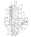
- the waveguide 317 has a tubular portion 320 opened at the bottom surface of the recess 15 and a horn portion 330 opened at the second surface 302 of the support plate 300 .
- the tubular portion 320 has a tubular shape with an opening width smaller than that of the concave portion 15 and the same opening width throughout the thickness direction.
- the horn portion 330 is opened in the thickness direction from the end portion communicating with the cylindrical portion 320 to the end portion (sound wave emitting port) opened in the second surface 302 of the support plate 300 . It has a horn shape with a large width.
- the sound pressure level of the sound waves emitted from the vibrating body formed by the piezoelectric element 30 and the flexible resin film 20 can be increased.
- the support plate 300 is divided into a portion (first plate 360 described below) in which the recess 15 is formed and a portion (second plate 360 described below) in which the waveguide 317 is formed. 370) can be changed to a separate support plate 350.
- FIG. 25 shows a partial vertical cross-sectional view of an ultrasonic transducer 2B according to a modification of the present embodiment, which includes the support plate 350. As shown in FIG.
- FIG. 26(a) shows a plan view of a model 220 (piezoelectric assembly) used in this analysis. Also, FIG. 26(b) shows a cross-sectional view taken along line XXVI-XXVI in FIG. 26(a). Furthermore, FIG. 27 shows an enlarged view of the XXVII part in FIG. 26(b).
- the cylindrical portion 320 has the same opening width throughout the thickness direction, and the opening width increases as it approaches the sound wave emission opening opened in the second surface 302 of the support plate 350 in the thickness direction.
- the relationship between the opening width D2a of the cylindrical portion 320 and the sound pressure level of the sound wave radiated by the vibrating body is analyzed by a finite element method. is obtained by
- the shape and dimensions of the piezoelectric element 30, the material and thickness of the flexible resin film 20, the opening width D1 of the recess 15, the portion where the recess 15 is formed (first plate 360) and the arrangement pitch P of the piezoelectric elements 30 were set as follows.
- the material of the portion (first plate 360) where the recess 15 is formed is SUS304, and the material of the portion (second plate 370) where the waveguide 317 is formed is SiC.
- the length L2a of the cylindrical portion 320 is set to a constant value (0.25 mm), and the opening width D2a is set as follows. set in the street.
- Example 5-(1): D2a 1.2 mm
- Example 5-(2): D2a 1.35 mm
- Example 5-(3): D2a 1.5 mm
- Example 5-(4): D2a 1.65 mm
- Example 5-(5): D2a 1.8 mm
- Example 5-(6): D2a 2.2 mm
- Example 5-(7): D2a 2.5 mm
- the opening width D2 of the waveguide 17 and the vibrating body The relationship between the radiated sound wave and the sound pressure level was obtained by the finite element method analysis.
- the opening width D2 (see FIG. 10(b)) is set as follows, and the other conditions are set as in Examples 5-(1) to 5-(4). Same as Example 5-(7).
- Fig. 28 shows the calculation results of this analysis (5).
- the configuration in which the waveguide 317 including the horn portion 330 is formed (Embodiment 5-(1) to Embodiment 5-(7)) has an opening width of The sound pressure level is remarkably high compared to the configuration (reference examples 5-(1) to 5-(4)) in which the tubular waveguide 17 having a constant .DELTA.
- the cylindrical portion 320 When the opening width D2a is 1.35 mm to 1.65 mm (that is, the opening width of the cylindrical portion 320 with respect to the wavelength ⁇ of the sound wave emitted by the vibrating body including the piezoelectric element 30 (wavelength 8.6 mm at a driving frequency of 40 kHz) When the ratio D2a/ ⁇ of D2a is 0.15 to 0.2), the sound pressure level was maximized.
- Fig. 29 shows the calculation results of this analysis (6).
- the length L2a of the cylindrical portion 320 is 0.75 mm or less (that is, the ratio L2a/ ⁇ of L2a to the wavelength ⁇ of the sound wave emitted by the vibrating body including the piezoelectric element 30 (wavelength 8.6 mm at a driving frequency of 40 kHz). 0.09 or less), and more preferably set L2a to 0.3 mm or less (that is, L2a/L ⁇ 0.035).
- Example 7-(1): D2b 1.5 mm
- Example 7-(2): D2b 2.0 mm
- Example 7-(3): D2b 3.0 mm
- Example 7-(4): D2b 3.7 mm
- Fig. 30 shows the calculation results of this analysis (7).
- the ratio of the radiation diameter D2b to the arrangement pitch P is preferably 0.8 to 0.95. That is, when the arrangement pitch P is set to 4.0 mm, it is preferable to set the radiation aperture D2b to 3.2 mm to 3.8 mm.
Landscapes
- Engineering & Computer Science (AREA)
- Manufacturing & Machinery (AREA)
- Mechanical Engineering (AREA)
- Physics & Mathematics (AREA)
- Acoustics & Sound (AREA)
- Signal Processing (AREA)
- Health & Medical Sciences (AREA)
- General Health & Medical Sciences (AREA)
- Otolaryngology (AREA)
- Transducers For Ultrasonic Waves (AREA)
Priority Applications (3)
| Application Number | Priority Date | Filing Date | Title |
|---|---|---|---|
| US18/274,938 US20240082877A1 (en) | 2021-02-03 | 2021-02-03 | Ultrasonic transducer and method for manufacturing the same |
| PCT/JP2021/003816 WO2022168188A1 (ja) | 2021-02-03 | 2021-02-03 | 超音波トランスデューサー及びその製造方法 |
| JP2021565782A JP7023436B1 (ja) | 2021-02-03 | 2021-02-03 | 超音波トランスデューサー及びその製造方法 |
Applications Claiming Priority (1)
| Application Number | Priority Date | Filing Date | Title |
|---|---|---|---|
| PCT/JP2021/003816 WO2022168188A1 (ja) | 2021-02-03 | 2021-02-03 | 超音波トランスデューサー及びその製造方法 |
Publications (1)
| Publication Number | Publication Date |
|---|---|
| WO2022168188A1 true WO2022168188A1 (ja) | 2022-08-11 |
Family
ID=81076728
Family Applications (1)
| Application Number | Title | Priority Date | Filing Date |
|---|---|---|---|
| PCT/JP2021/003816 Ceased WO2022168188A1 (ja) | 2021-02-03 | 2021-02-03 | 超音波トランスデューサー及びその製造方法 |
Country Status (3)
| Country | Link |
|---|---|
| US (1) | US20240082877A1 (https=) |
| JP (1) | JP7023436B1 (https=) |
| WO (1) | WO2022168188A1 (https=) |
Families Citing this family (4)
| Publication number | Priority date | Publication date | Assignee | Title |
|---|---|---|---|---|
| CN114864806B (zh) * | 2022-06-01 | 2026-02-03 | 上海交通大学 | 具有短波导结构的超声换能器及制造方法、超声检测装置 |
| CN114947946A (zh) * | 2022-06-01 | 2022-08-30 | 上海交通大学 | 柔性超声换能器及其制造方法、超声检测装置 |
| US20260097418A1 (en) * | 2022-12-08 | 2026-04-09 | Suncall Corporation | Ultrasonic Transducer Array and Ultrasonic Phased Array Sensor |
| JP7671420B2 (ja) * | 2023-03-27 | 2025-05-01 | サンコール株式会社 | 圧電素子、超音波トランスデューサー及びその製造方法 |
Citations (2)
| Publication number | Priority date | Publication date | Assignee | Title |
|---|---|---|---|---|
| JP2020115940A (ja) * | 2019-01-18 | 2020-08-06 | コニカミノルタ株式会社 | 超音波プローブ、及び超音波診断装置 |
| JP6776481B1 (ja) * | 2020-01-30 | 2020-10-28 | サンコール株式会社 | 超音波トランスデューサー及びその製造方法 |
-
2021
- 2021-02-03 WO PCT/JP2021/003816 patent/WO2022168188A1/ja not_active Ceased
- 2021-02-03 JP JP2021565782A patent/JP7023436B1/ja active Active
- 2021-02-03 US US18/274,938 patent/US20240082877A1/en active Pending
Patent Citations (2)
| Publication number | Priority date | Publication date | Assignee | Title |
|---|---|---|---|---|
| JP2020115940A (ja) * | 2019-01-18 | 2020-08-06 | コニカミノルタ株式会社 | 超音波プローブ、及び超音波診断装置 |
| JP6776481B1 (ja) * | 2020-01-30 | 2020-10-28 | サンコール株式会社 | 超音波トランスデューサー及びその製造方法 |
Also Published As
| Publication number | Publication date |
|---|---|
| JP7023436B1 (ja) | 2022-02-21 |
| US20240082877A1 (en) | 2024-03-14 |
| JPWO2022168188A1 (https=) | 2022-08-11 |
Similar Documents
| Publication | Publication Date | Title |
|---|---|---|
| WO2022168188A1 (ja) | 超音波トランスデューサー及びその製造方法 | |
| JP6776481B1 (ja) | 超音波トランスデューサー及びその製造方法 | |
| CN106416295B (zh) | 具有声能反射中间层的微机电声换能器 | |
| JP5815833B2 (ja) | 音響発生器およびそれを用いた音響発生装置 | |
| JP6598417B1 (ja) | 超音波トランスデューサー及びその製造方法 | |
| WO2023095829A1 (ja) | 超音波トランスデューサ | |
| JP6496097B1 (ja) | 超音波トランスデューサー及びその製造方法 | |
| CN105324184B (zh) | 电声转换器 | |
| JP6024655B2 (ja) | 発振装置、および電子機器 | |
| JP7139545B1 (ja) | 超音波トランスデューサー | |
| JP7154462B1 (ja) | 超音波トランスデューサー及びその製造方法 | |
| CN111512643B (zh) | 压电元件 | |
| JP6552149B1 (ja) | 超音波トランスデューサー及びその製造方法 | |
| JP7486670B2 (ja) | 圧電素子アッセンブリ及びその製造方法 | |
| JP5771135B2 (ja) | 球面状複合多チャンネル圧電振動子及びその製造方法 | |
| JP2000088822A (ja) | 超音波探触子 | |
| JP2012217037A (ja) | 電子機器 | |
| JP6595248B2 (ja) | 音響発生器 | |
| JP2022103942A (ja) | 超音波トランスデューサ | |
| JP6595280B2 (ja) | 音響発生器 | |
| CN119450320A (zh) | 具有压电元件的变换器及其制造方法 |
Legal Events
| Date | Code | Title | Description |
|---|---|---|---|
| ENP | Entry into the national phase |
Ref document number: 2021565782 Country of ref document: JP Kind code of ref document: A |
|
| 121 | Ep: the epo has been informed by wipo that ep was designated in this application |
Ref document number: 21924585 Country of ref document: EP Kind code of ref document: A1 |
|
| WWE | Wipo information: entry into national phase |
Ref document number: 18274938 Country of ref document: US |
|
| NENP | Non-entry into the national phase |
Ref country code: DE |
|
| 122 | Ep: pct application non-entry in european phase |
Ref document number: 21924585 Country of ref document: EP Kind code of ref document: A1 |