WO2022163704A1 - 定着パッド - Google Patents
定着パッド Download PDFInfo
- Publication number
- WO2022163704A1 WO2022163704A1 PCT/JP2022/002896 JP2022002896W WO2022163704A1 WO 2022163704 A1 WO2022163704 A1 WO 2022163704A1 JP 2022002896 W JP2022002896 W JP 2022002896W WO 2022163704 A1 WO2022163704 A1 WO 2022163704A1
- Authority
- WO
- WIPO (PCT)
- Prior art keywords
- sliding member
- adhesive
- fixing pad
- fixing
- base material
- Prior art date
- Legal status (The legal status is an assumption and is not a legal conclusion. Google has not performed a legal analysis and makes no representation as to the accuracy of the status listed.)
- Ceased
Links
Images


Classifications
-
- G—PHYSICS
- G03—PHOTOGRAPHY; CINEMATOGRAPHY; ANALOGOUS TECHNIQUES USING WAVES OTHER THAN OPTICAL WAVES; ELECTROGRAPHY; HOLOGRAPHY
- G03G—ELECTROGRAPHY; ELECTROPHOTOGRAPHY; MAGNETOGRAPHY
- G03G15/00—Apparatus for electrographic processes using a charge pattern
- G03G15/20—Apparatus for electrographic processes using a charge pattern for fixing, e.g. by using heat
Definitions
- the present invention relates to a fixing pad.
- Patent Literature 1 discloses a structure in which a fabric made of fluorine fiber or the like is wound on the surface of a sliding member parallel to the sliding direction.
- the sliding surface of the sliding member is preferably smooth from the viewpoint of thermal conductivity and low friction with the fixing belt.
- Patent Document 1 since the fabric is wound and fixed in the sliding direction of the sliding member, the smooth surface cannot be maintained due to slippage and loosening of the fabric over time, and image quality deteriorates over time. is concerned.
- SUMMARY OF THE INVENTION It is an object of the present invention to provide a fixing pad that prevents displacement and loosening of a sliding member over time and has a smooth sliding surface.
- the present invention comprises a substrate, an adhesive, and a sliding member in this order, the sliding member comprising at least one woven or knitted fabric containing fluorine fibers, and the sliding member being impregnated with the adhesive. fusing pad.
- the adhesive is a silicone rubber adhesive, and is preferably impregnated to at least 10% of the thickness of the sliding member from the substrate side surface of the sliding member.
- the surface roughness Ra of the sliding surface of the sliding member is preferably 16 ⁇ m or less.
- the thickness of the sliding member is preferably 300 ⁇ m or more and 1000 ⁇ m or less.
- the cross-sectional shape of the substrate in the transverse direction is preferably U-shaped or arc-shaped.
- the sliding member is prevented from slipping and loosening, and has a smooth sliding surface.
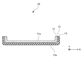
- FIG. 1 is a schematic cross-sectional view showing one embodiment of a fixing pad of the present invention
- FIG. FIG. 2 is a schematic cross-sectional view showing a state impregnated with an adhesive in the fixing pad of the present invention
- 1 is a schematic cross-sectional view of a toner fixing device provided with a fixing pad of the present invention
- FIG. 4 is a schematic cross-sectional view showing another embodiment of the fixing pad of the present invention
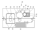
- 1 is a schematic cross-sectional view showing an example of an image forming apparatus equipped with a fixing pad of the present invention
- a fixing pad according to one embodiment of the present invention is the fixing pad 10 arranged to face the pressure roller 23 in the toner fixing device 20 (see FIG. 3).
- the fixing pad 10 will be described with reference to FIG.
- FIG. 1 is a cross-sectional view of the fixing pad 10 in a direction perpendicular to the longitudinal direction Y (lateral direction X).
- the fixing pad 10 comprises a substrate 11, an adhesive 12 and a sliding member 13 provided on the surface 11a of the substrate 11 facing the pressure roller, in this order. be. That is, the base material 11 and the sliding member 13 are adhered with the adhesive 12 .
- the surface 11a of the base material 11 facing the pressure roller is also referred to as a surface to which the sliding member 13 is adhered. Details of each configuration will be described below.
- the base material 11 aluminum (including aluminum alloys), copper, iron, stainless steel, brass, sulfur free-cutting steel (SUM), and nickel- or zinc-plated surfaces of these metals can be used. .
- the substrate 11 is preferably made of aluminum or copper from the viewpoint of thermal conductivity.
- the base material 11 may be composed of one material, or may be composed of two or more materials. Moreover, the base material 11 may have a laminated structure.
- the region of the substrate 11 forming a nip with the pressure roller 23 is flat and has a U-shaped cross section in the transverse direction.
- the base material 11 may have an arcuate cross-sectional shape in the transverse direction. Since the cross-sectional shape of the base material 11 in the lateral direction is U-shaped or arc-shaped, the fixing belt 21 can smoothly slide without being caught on the corners of the fixing pad 10 .
- the length of the base material 11 in the longitudinal direction Y is not particularly limited, and may be appropriately adjusted according to the form of the installed image forming apparatus.
- the length of the substrate 11 in the longitudinal direction Y is preferably 200 mm or more and 400 mm or less, and more preferably 250 mm or more and 370 mm or less.
- the length of the base material 11 in the transverse direction X is not particularly limited, and may be appropriately adjusted according to the form of the installed image forming apparatus.
- the length of the substrate 11 in the transverse direction X is preferably 8 mm or more and 30 mm or less, more preferably 15 mm or more and 25 mm or less.
- the thickness of the base material 11 is preferably 0.2 mm or more and 1.0 mm or less, and more preferably 0.3 mm or more and 0.6 mm or less.
- the adhesive 12 is preferably a silicone rubber adhesive from the viewpoint of good adhesion between the sliding member 13 and the base material 11 .
- silicone rubber adhesive one-component curing type rubber is preferable, and one-component liquid silicone rubber, one-component silicone RTV rubber, and the like can be mentioned.
- Commercially available products include KE-1880 (manufactured by Shin-Etsu Chemical Co., Ltd.), KE-1833 (manufactured by Shin-Etsu Chemical Co., Ltd.), and TSE322 (manufactured by Momentive Japan).
- the sliding member 13 is made of at least one woven or knitted fabric containing fluorine fibers.
- a woven fabric is preferable from the viewpoint of maintaining smoothness over a long period of time.
- Plain weave, twill weave, satin weave and the like can be used as the weaving method of the fluorine fiber fabric.
- Polytetrafluoroethylene fibers and polyfluoroethylene fibers are preferred as fluorine fibers.
- Polytetrafluoroethylene materials include homopolymers of tetrafluoroethylene or copolymers in which 90 mol % or more, preferably 95 mol % or more of the total is tetrafluoroethylene.
- Examples of monomers copolymerizable with tetrafluoroethylene include vinyl fluoride compounds such as trifluoroethylene, trifluorochloroethylene, tetrafluoropropylene and hexafluoropropylene, and further propylene, ethylene, isobutylene, styrene, acrylonitrile and the like. Examples include vinyl compounds. From the viewpoint of reducing the friction of the sliding surface, the content of tetrafluoroethylene units is preferably large, and a homopolymer is more preferable.
- Fluorine fibers may be monofilaments, multifilaments, or spun yarns.
- the total fineness of the monofilament or multifilament fibers is preferably 50 to 2000 dtex, more preferably 100 to 1000 dtex.
- the strength of the fibers increases and the resistance to yarn breakage increases. If it is 2000 dtex or less, the unevenness of the surface when the fibers are arranged in parallel is small, so there is no influence on the slidability, and the flexibility is high, so it can easily conform to the shape of the base material 11 .
- the surface roughness Ra of the sliding surface 13a of the sliding member 13 is preferably 16 ⁇ m or less, more preferably 0.5 ⁇ m or more and 16 ⁇ m or less, and even more preferably 1 ⁇ m or more and 10 ⁇ m or less.
- the method of measuring the surface roughness Ra shall be that in Examples described later.
- the sliding surface 13a When the surface roughness Ra of the sliding surface 13a is within the above range, the sliding surface 13a can be made smooth even though it is a woven or knitted fabric, and heat can be conducted well to the fixing belt. , a high-quality image can be obtained.
- the sliding member 13 is preferably formed by subjecting the sliding member 13 made of the woven fabric or knitted fabric to hot press processing or cold press processing.
- Hot press processing can be performed with a known hot press machine.
- the heating temperature depends on the material of the sliding member 13, it is preferably 100° C. or higher and 200° C. or lower.
- the pressure depends on the material and desired thickness of the sliding member 13, it is preferably 2 MPa or more and 10 MPa or less.
- the thickness t13 of the sliding member 13 is preferably 300 ⁇ m or more and 1000 ⁇ m or less, more preferably 400 ⁇ m or more and 600 ⁇ m or less.
- the method of measuring the thickness t13 of the sliding member 13 shall be that in the examples described later.
- a fixing pad can be manufactured, for example, as follows. First, the surface 11a of the substrate 11 to which the sliding member 13 is adhered is cleaned with alcohol or the like. Next, the sliding member 13 cut larger than the size of the base material 11 is placed on a workbench, and the adhesive 12 is applied thereon by a bar coater, squeegee, or the like. Then, the sliding member 13 coated with the adhesive 12 and the base material 11 arranged thereon are placed in a mold of the same type as the base material 11, and the adhesive 12 is cured while being heated and pressed. Let Although the heating temperature at this time depends on the material and thickness of the sliding member 13, it is preferably 100° C. or higher and 200° C. or lower. Although the pressure depends on the material and desired thickness of the sliding material, it is preferably 2 MPa or more and 10 MPa or less. Finally, the excess sliding member 13 is cut off to complete the fixing pad 10 .
- the sliding member 13 is impregnated with the adhesive 12 as shown in FIG. 2 by curing the adhesive 12 while applying heat and pressure as described above.
- a region 14 in FIG. 2 schematically shows a region of the sliding member 13 impregnated with the adhesive 12 .
- the sliding member 13 is firmly adhered to the base material 11 by the adhesive 12 entering the weaves or stitches of the sliding member 13 .
- the adhesive 12 is preferably impregnated from the base 11 side surface 13b of the sliding member 13 to at least 10% of the thickness t13 of the sliding member 13. As shown in FIG.
- the adhesive 12 is more preferably impregnated in an area of 35% or more and 80% or less from the surface 13b of the sliding member 13 on the base material 11 side, and is impregnated in an area of 45% or more and 80% or less from the surface 13b. More preferably. Since the region impregnated with the adhesive 12 is within the above range, the base material 11 and the sliding member 13 are prevented from leaking out of the adhesive 12 from the weaves or stitches of the sliding member 13 onto the sliding surface 13a. Since the two are strongly bonded together, the sliding member 13 is prevented from slipping and loosening, and a high-quality image can be obtained.
- the material of the impregnated adhesive 12 is silicone rubber, it has the effect of absorbing the stress caused by the displacement of the sliding member because it is a stretchable material. Furthermore, since the sliding member 13 is flexibly deformed when used in contact with the fixing belt, the load on the fixing belt is favorably reduced.
- the sliding member 13 is provided on the entire surface 11 a of the base material 11 facing the pressure roller 23 . Since the fixing belt 21 is provided on the entire surface 11 a , the fixing belt 21 can smoothly slide without being caught by the corners of the sliding member 13 .
- the sliding member 13 may not be provided on the entire surface 11a, and may be provided at least in an area where a desired nip width with the pressure roller 23 can be secured.
- a primer layer may be provided by applying a primer to the surface 11a of the base material 11 to which the sliding member 13 is adhered before applying the adhesive 12 . Thereby, the adhesion between the base material 11 and the adhesive 12 becomes stronger.
- primers include No. 4 (manufactured by Shin-Etsu Chemical Co., Ltd.) and No. 33 (manufactured by Shin-Etsu Chemical Co., Ltd.).
- the fixing pad 10 of the present invention is used in a toner fixing device 20 of an image forming apparatus, as shown in FIG.
- the fixing pad 10 is arranged to face the pressure roller 23 and is pressed against each other with a predetermined nip width.
- the pressure roller 23 has an elastic body 25 and a coating layer 26 on the outer periphery of the shaft 24, and is driven to rotate by driving means (not shown).
- a fixing belt 21 is wound around the fixing pad 10 , and the rotation of the pressure roller 23 causes the fixing belt 21 to rotate.
- the fixing pad 10 is connected to a heating device 22 , and the sliding surface 13 a of the fixing pad 10 is heated by the heating device 22 , thereby heating the fixing belt 21 .
- the pressure roller 23 is also heated by heating means (not shown). While the fixing belt 21 and the pressure roller 23 are heated, when the recording medium 36 with the developer 42 transferred thereon is transported and brought into pressure contact between the fixing belt 21 and the pressure roller 23 , the developer 42 is fixed on the recording medium 36 by being heated and
- the image forming apparatus 30 includes a rotatable image carrier 31, such as a photosensitive member, on which an electrostatic latent image is formed, and a charging roller 32 and exposure means arranged around the image carrier 31. 33, a developing means 40, a transfer roller 34, an image carrier cleaning roller 35, and a toner fixing device 20 on the downstream side of the recording medium 36 in the conveying direction.
- the toner fixing device 20 includes the pressure roller 23, the fixing pad 10 arranged to face the pressure roller 23, the heating device 22, and the fixing belt (endless belt) 21, as described above.
- a heating device (not shown) is also connected to the pressure roller 23 .
- the developing means 40 includes a developer accommodating portion 41, a developer carrier 44 that supplies the developer 42 to the image carrier 31, a developer supply means 43 that supplies the developer 42 to the developer carrier 44, and a developer. and a developer regulating member 45 that charges the developer 42 .
- the developer 42 may be a dry developer or a wet developer as long as it is a one-component developer, and may be a non-magnetic developer or a magnetic developer.
- the toner fixing device 20 includes a heating device that fixes the developer 42 (electrostatic latent image) transferred to the recording medium 36 .
- the toner fixing device 20 is arranged in a housing 27 having an opening 28 through which the recording medium 36 passes, and includes a fixing pad 10 , a fixing belt 21 , and a pressure roller 23 arranged to face the fixing pad 10 .
- It is a pressure heat fixing device in which a fixing pad 10 and a pressure roller 23 are rotatably supported so as to abut or press against each other via a fixing belt 21 .
- the image forming apparatus 30 operates as follows. First, in the image forming apparatus 30 , the charging roller 32 uniformly charges the image carrier 31 , and the exposure means 33 forms an electrostatic latent image on the surface of the image carrier 31 . Next, developer 42 is supplied from developing means 40 to image carrier 31 to develop the electrostatic latent image. The developer image is then transferred onto a recording medium 36 conveyed between the image carrier 31 and transfer roller 34 . This recording medium 36 is conveyed to the toner fixing device 20, and the developer image is fixed on the recording medium 36 as a permanent image. An image can be formed on the recording medium 36 in this way. After the developer image has been transferred, the image carrier 31 is cleaned by an image carrier cleaning roller 35 disposed on the upstream side of the charging roller 32 to remove the developer adhering to or remaining on the outer peripheral surface of the image carrier 31 .
- the image forming apparatus 30 of the present embodiment is an electrophotographic image forming apparatus, but in the present invention, the image forming apparatus is not limited to an electrophotographic image forming apparatus, for example, an electrostatic image forming apparatus. may be Further, the image forming apparatus 30 is a monochrome image forming apparatus that stores only a single-color developer 42 in the developing means 40, but in the present invention, the image forming apparatus is not limited to a monochrome image forming apparatus. A four-cycle type color image forming apparatus may be used in which the primary transfer of developer images carried on a bearing member is sequentially repeated onto an intermediate transfer member.
- a color image forming apparatus for example, an image forming apparatus on an image carrier, a tandem type color image forming apparatus in which a plurality of image carriers provided with developing means for each color are arranged in series on an intermediate transfer member or a transfer/transport belt, and the like. is mentioned.
- the image forming apparatus 30 is, for example, an image forming apparatus such as a copier, facsimile machine, or printer.
- a one-component developer is advantageously used as the developer 42, but a two-component developer containing toner and a carrier such as iron or nickel can also be used. .
- image forming apparatus 30 is not limited to the above-described embodiment, and various modifications are possible within the scope of achieving the object of the present invention.
- image forming apparatuses include various image forming apparatuses, and an image forming apparatus capable of forming images at high speed is preferable.
- Example 1 A fixing pad was made using the following materials.
- Base material copper plate thickness 0.4mm
- Examples 2 to 4 and Comparative Example 1 A fixing pad was produced in the same manner as in Example 1, except that the thickness of the impregnated adhesive and the impregnation ratio were as shown in Table 1.
- ⁇ Thickness of sliding member> instead of a copper plate, an iron plate coated with a release agent was used as the base material, and an adhesive was applied. , pressed for 3 minutes. After that, the sliding member with the adhesive was peeled off from the iron plate, and this was used as a sample for measurement.
- the thickness of the sliding member was measured from the cross section with a shape analysis laser microscope (model number: VK-X1000, manufactured by Keyence Corporation). The sample size was 140 mm ⁇ 25 mm. Three points L (left end), C (center), and R (right end) were measured in the longitudinal direction, and the average value was obtained. For L (left end) and R (right end), measurements were taken at points 10.0 mm inside from both ends, and at the central point in the width direction.
- Impregnation ratio (%) thickness of adhesive impregnated in sliding member/thickness of sliding member ⁇ 100
- Measuring equipment Ueshima Seisakusho De Mattia bending tester, model number: FT-1520 Test conditions: stroke 20 mm, temperature 20°C, number of times 100,000, speed 300 rpm Sample size: 140mm x 25mm thickness 500 ⁇ m (based on JIS K 6260 5.1) A sample of the above size was cut out from a sample for measurement, and a bending test was performed three times.
- the surface roughness Ra of the sliding surface before and after the bending test was measured using the following measuring equipment and conditions.
- Measuring instrument Surface roughness shape measuring machine (model number: SURFCOM 1400D-3DF, manufactured by Tokyo Seimitsu Co., Ltd.)
- Parameter calculation standard JIS'01 standard Cutoff type: Gaussian Measurement length: 20.0 mm
- Measurement speed 0.3mm/sec
- the longitudinal direction C was measured before and after the flex test, and the three values were averaged.
- the width direction the central portion was measured.
- a difference (absolute value) in surface roughness Ra of the sliding surface before and after the bending test was determined and evaluated according to the following criteria.
- -criterion- A No change in the surface of the sliding portion, or a difference in surface roughness Ra of less than 1 ⁇ m before and after the Dematcher test
- B A difference in surface roughness Ra of 1 ⁇ m or more and 2 ⁇ m or less before and after the Dematcher test
- C Surface roughness before and after the Dematcher test The difference in height Ra is more than 2 ⁇ m
- the sliding surface of the fixing pad of the present invention has no change in surface roughness Ra or a difference in surface roughness Ra of less than 1 ⁇ m even after the bending test. That is, in the fixing pad of the present invention, the base material and the sliding member are firmly bonded, the sliding member is well prevented from slipping and loosening with use over time, and the fixing pad has a smooth sliding surface. I found out.
Landscapes
- Physics & Mathematics (AREA)
- General Physics & Mathematics (AREA)
- Fixing For Electrophotography (AREA)
Priority Applications (2)
| Application Number | Priority Date | Filing Date | Title |
|---|---|---|---|
| JP2022578446A JPWO2022163704A1 (https=) | 2021-01-28 | 2022-01-26 | |
| CN202290000256.0U CN220752528U (zh) | 2021-01-28 | 2022-01-26 | 定影垫 |
Applications Claiming Priority (2)
| Application Number | Priority Date | Filing Date | Title |
|---|---|---|---|
| JP2021-012126 | 2021-01-28 | ||
| JP2021012126 | 2021-01-28 |
Publications (1)
| Publication Number | Publication Date |
|---|---|
| WO2022163704A1 true WO2022163704A1 (ja) | 2022-08-04 |
Family
ID=82653605
Family Applications (1)
| Application Number | Title | Priority Date | Filing Date |
|---|---|---|---|
| PCT/JP2022/002896 Ceased WO2022163704A1 (ja) | 2021-01-28 | 2022-01-26 | 定着パッド |
Country Status (3)
| Country | Link |
|---|---|
| JP (1) | JPWO2022163704A1 (https=) |
| CN (1) | CN220752528U (https=) |
| WO (1) | WO2022163704A1 (https=) |
Families Citing this family (1)
| Publication number | Priority date | Publication date | Assignee | Title |
|---|---|---|---|---|
| CN116802567B (zh) * | 2021-01-28 | 2025-12-09 | 信越聚合物株式会社 | 定影垫 |
Citations (3)
| Publication number | Priority date | Publication date | Assignee | Title |
|---|---|---|---|---|
| JP2008197317A (ja) * | 2007-02-13 | 2008-08-28 | Nitto Denko Corp | 画像定着装置および摺動シート |
| JP2013171171A (ja) * | 2012-02-21 | 2013-09-02 | Fuji Xerox Co Ltd | 定着装置用摺動部材、定着装置、及び画像形成装置 |
| JP2016153872A (ja) * | 2015-02-17 | 2016-08-25 | 東レプラスチック精工株式会社 | 定着具およびその製造方法 |
Family Cites Families (2)
| Publication number | Priority date | Publication date | Assignee | Title |
|---|---|---|---|---|
| JP2014186303A (ja) * | 2013-02-25 | 2014-10-02 | Ricoh Co Ltd | 定着装置および画像形成装置 |
| JP2018097072A (ja) * | 2016-12-09 | 2018-06-21 | コニカミノルタ株式会社 | 押圧パッド、およびそれを利用する定着装置と画像形成装置 |
-
2022
- 2022-01-26 JP JP2022578446A patent/JPWO2022163704A1/ja active Pending
- 2022-01-26 CN CN202290000256.0U patent/CN220752528U/zh active Active
- 2022-01-26 WO PCT/JP2022/002896 patent/WO2022163704A1/ja not_active Ceased
Patent Citations (3)
| Publication number | Priority date | Publication date | Assignee | Title |
|---|---|---|---|---|
| JP2008197317A (ja) * | 2007-02-13 | 2008-08-28 | Nitto Denko Corp | 画像定着装置および摺動シート |
| JP2013171171A (ja) * | 2012-02-21 | 2013-09-02 | Fuji Xerox Co Ltd | 定着装置用摺動部材、定着装置、及び画像形成装置 |
| JP2016153872A (ja) * | 2015-02-17 | 2016-08-25 | 東レプラスチック精工株式会社 | 定着具およびその製造方法 |
Also Published As
| Publication number | Publication date |
|---|---|
| JPWO2022163704A1 (https=) | 2022-08-04 |
| CN220752528U (zh) | 2024-04-09 |
Similar Documents
| Publication | Publication Date | Title |
|---|---|---|
| US7493074B2 (en) | Fixing device, sheet member, and image forming apparatus | |
| US7142803B2 (en) | Fixing device and image forming apparatus | |
| US8326200B2 (en) | Fixing device, image forming apparatus and method of controlling fixing device | |
| JP7570291B2 (ja) | 定着パッド | |
| US7515858B2 (en) | Fluorocarbon resin-coated member with a specified relative film density, manufacturing method thereof, fixing device using the member, and image forming apparatus using the device | |
| WO2022163704A1 (ja) | 定着パッド | |
| US6782233B2 (en) | Externally heated thick belt fuser | |
| US8385805B2 (en) | Fixing member, fixing apparatus and image forming apparatus | |
| WO2022163702A1 (ja) | 定着パッド | |
| JP2010078863A (ja) | 無端ベルト、定着装置及び画像形成装置 | |
| JP2024172738A (ja) | 定着パッド | |
| JP4984820B2 (ja) | 定着装置及び画像形成装置 | |
| JP2010197579A (ja) | 無端ベルト、画像定着装置、及び画像形成装置 | |
| JP3910780B2 (ja) | 画像定着ユニット | |
| JP5070739B2 (ja) | 画像形成装置、定着装置、定着部材、および定着部材の製造方法 | |
| JP5089083B2 (ja) | 画像加熱装置 | |
| JP3269544B2 (ja) | 定着装置及び定着用エンドレスベルト | |
| JP3233349B2 (ja) | 定着装置及び定着用エンドレスベルト | |
| JP2006267408A (ja) | 定着装置、ベルト管状体、および画像形成装置 | |
| CN112558450A (zh) | 图像形成装置用滑动部件、定影装置和图像形成装置 | |
| JP6361136B2 (ja) | 定着ベルト、定着装置及び画像形成装置 | |
| JPH0876625A (ja) | シリコーン及びバイトンの定着ローラ | |
| JP2010026093A (ja) | 無端ベルト、定着装置及び画像形成装置 | |
| JP2004109668A (ja) | 定着用フィルム管状体、及びそれを用いた定着装置 | |
| JP4682659B2 (ja) | ベルト管状体、定着装置、および画像形成装置 |
Legal Events
| Date | Code | Title | Description |
|---|---|---|---|
| 121 | Ep: the epo has been informed by wipo that ep was designated in this application |
Ref document number: 22745923 Country of ref document: EP Kind code of ref document: A1 |
|
| ENP | Entry into the national phase |
Ref document number: 2022578446 Country of ref document: JP Kind code of ref document: A |
|
| WWE | Wipo information: entry into national phase |
Ref document number: 202290000256.0 Country of ref document: CN |
|
| NENP | Non-entry into the national phase |
Ref country code: DE |
|
| 122 | Ep: pct application non-entry in european phase |
Ref document number: 22745923 Country of ref document: EP Kind code of ref document: A1 |