WO2022163675A1 - 密封装置 - Google Patents
密封装置 Download PDFInfo
- Publication number
- WO2022163675A1 WO2022163675A1 PCT/JP2022/002760 JP2022002760W WO2022163675A1 WO 2022163675 A1 WO2022163675 A1 WO 2022163675A1 JP 2022002760 W JP2022002760 W JP 2022002760W WO 2022163675 A1 WO2022163675 A1 WO 2022163675A1
- Authority
- WO
- WIPO (PCT)
- Prior art keywords
- lip
- conductive
- inner peripheral
- axis
- sealing device
- Prior art date
- Legal status (The legal status is an assumption and is not a legal conclusion. Google has not performed a legal analysis and makes no representation as to the accuracy of the status listed.)
- Ceased
Links
Images


Classifications
-
- F—MECHANICAL ENGINEERING; LIGHTING; HEATING; WEAPONS; BLASTING
- F16—ENGINEERING ELEMENTS AND UNITS; GENERAL MEASURES FOR PRODUCING AND MAINTAINING EFFECTIVE FUNCTIONING OF MACHINES OR INSTALLATIONS; THERMAL INSULATION IN GENERAL
- F16J—PISTONS; CYLINDERS; SEALINGS
- F16J15/00—Sealings
- F16J15/16—Sealings between relatively-moving surfaces
- F16J15/32—Sealings between relatively-moving surfaces with elastic sealings, e.g. O-rings
- F16J15/3204—Sealings between relatively-moving surfaces with elastic sealings, e.g. O-rings with at least one lip
- F16J15/3228—Sealings between relatively-moving surfaces with elastic sealings, e.g. O-rings with at least one lip formed by deforming a flat ring
-
- F—MECHANICAL ENGINEERING; LIGHTING; HEATING; WEAPONS; BLASTING
- F16—ENGINEERING ELEMENTS AND UNITS; GENERAL MEASURES FOR PRODUCING AND MAINTAINING EFFECTIVE FUNCTIONING OF MACHINES OR INSTALLATIONS; THERMAL INSULATION IN GENERAL
- F16J—PISTONS; CYLINDERS; SEALINGS
- F16J15/00—Sealings
- F16J15/16—Sealings between relatively-moving surfaces
- F16J15/32—Sealings between relatively-moving surfaces with elastic sealings, e.g. O-rings
- F16J15/3284—Sealings between relatively-moving surfaces with elastic sealings, e.g. O-rings characterised by their structure; Selection of materials
-
- F—MECHANICAL ENGINEERING; LIGHTING; HEATING; WEAPONS; BLASTING
- F16—ENGINEERING ELEMENTS AND UNITS; GENERAL MEASURES FOR PRODUCING AND MAINTAINING EFFECTIVE FUNCTIONING OF MACHINES OR INSTALLATIONS; THERMAL INSULATION IN GENERAL
- F16J—PISTONS; CYLINDERS; SEALINGS
- F16J15/00—Sealings
- F16J15/16—Sealings between relatively-moving surfaces
- F16J15/32—Sealings between relatively-moving surfaces with elastic sealings, e.g. O-rings
- F16J15/3204—Sealings between relatively-moving surfaces with elastic sealings, e.g. O-rings with at least one lip
- F16J15/3232—Sealings between relatively-moving surfaces with elastic sealings, e.g. O-rings with at least one lip having two or more lips
-
- F—MECHANICAL ENGINEERING; LIGHTING; HEATING; WEAPONS; BLASTING
- F16—ENGINEERING ELEMENTS AND UNITS; GENERAL MEASURES FOR PRODUCING AND MAINTAINING EFFECTIVE FUNCTIONING OF MACHINES OR INSTALLATIONS; THERMAL INSULATION IN GENERAL
- F16J—PISTONS; CYLINDERS; SEALINGS
- F16J15/00—Sealings
- F16J15/16—Sealings between relatively-moving surfaces
- F16J15/32—Sealings between relatively-moving surfaces with elastic sealings, e.g. O-rings
- F16J15/324—Arrangements for lubrication or cooling of the sealing itself
-
- F—MECHANICAL ENGINEERING; LIGHTING; HEATING; WEAPONS; BLASTING
- F16—ENGINEERING ELEMENTS AND UNITS; GENERAL MEASURES FOR PRODUCING AND MAINTAINING EFFECTIVE FUNCTIONING OF MACHINES OR INSTALLATIONS; THERMAL INSULATION IN GENERAL
- F16J—PISTONS; CYLINDERS; SEALINGS
- F16J15/00—Sealings
- F16J15/16—Sealings between relatively-moving surfaces
- F16J15/32—Sealings between relatively-moving surfaces with elastic sealings, e.g. O-rings
- F16J15/3244—Sealings between relatively-moving surfaces with elastic sealings, e.g. O-rings with hydrodynamic pumping action
-
- F—MECHANICAL ENGINEERING; LIGHTING; HEATING; WEAPONS; BLASTING
- F16—ENGINEERING ELEMENTS AND UNITS; GENERAL MEASURES FOR PRODUCING AND MAINTAINING EFFECTIVE FUNCTIONING OF MACHINES OR INSTALLATIONS; THERMAL INSULATION IN GENERAL
- F16J—PISTONS; CYLINDERS; SEALINGS
- F16J15/00—Sealings
- F16J15/16—Sealings between relatively-moving surfaces
- F16J15/32—Sealings between relatively-moving surfaces with elastic sealings, e.g. O-rings
- F16J15/3248—Sealings between relatively-moving surfaces with elastic sealings, e.g. O-rings provided with casings or supports
- F16J15/3252—Sealings between relatively-moving surfaces with elastic sealings, e.g. O-rings provided with casings or supports with rigid casings or supports
-
- H—ELECTRICITY
- H02—GENERATION; CONVERSION OR DISTRIBUTION OF ELECTRIC POWER
- H02K—DYNAMO-ELECTRIC MACHINES
- H02K11/00—Structural association of dynamo-electric machines with electric components or with devices for shielding, monitoring or protection
- H02K11/40—Structural association with grounding devices
-
- H—ELECTRICITY
- H02—GENERATION; CONVERSION OR DISTRIBUTION OF ELECTRIC POWER
- H02K—DYNAMO-ELECTRIC MACHINES
- H02K7/00—Arrangements for handling mechanical energy structurally associated with dynamo-electric machines, e.g. structural association with mechanical driving motors or auxiliary dynamo-electric machines
- H02K7/08—Structural association with bearings
-
- H—ELECTRICITY
- H05—ELECTRIC TECHNIQUES NOT OTHERWISE PROVIDED FOR
- H05F—STATIC ELECTRICITY; NATURALLY-OCCURRING ELECTRICITY
- H05F3/00—Carrying-off electrostatic charges
- H05F3/02—Carrying-off electrostatic charges by means of earthing connections
Definitions
- the present disclosure relates to a sealing device, and more particularly to a sealing device used for a motor or its vicinity.
- Hybrid vehicles and electric vehicles use a drive motor as a power source.
- the induced current generated by the drive motor becomes electromagnetic noise, which may affect the electronic devices of the vehicle.
- the seal member made of conductive rubber can save space and reduce costs.
- the seal member is in contact with the shaft that rotates at high speed, and the resulting heat generation (sliding heat generation) may deteriorate the seal member. Then, there is a possibility that the sealing performance may deteriorate, and the conductive performance may deteriorate. In this way, it is required to prevent deterioration due to heat generation for a conductive sealing member for suppressing electromagnetic noise.
- An object of the present disclosure is to provide a sealing device that can prevent deterioration due to heat generation.
- a sealing device for sealing an annular space between an inner peripheral member and an outer peripheral member, a metal retaining ring annular about the axis; A seal lip that is fixed to the retaining ring on the outer peripheral side and has an annular shape around the axis, A seal portion extending obliquely with respect to the axis and forming an end on the inner peripheral side, the seal portion having a first inner peripheral surface in contact with the inner peripheral member on the inner peripheral side.
- a conductive lip fixed to the retaining ring on the outer peripheral side and having an annular conductivity around the axis A conductive lip extending obliquely with respect to the axis and forming an end on the inner peripheral side, the contact portion having a second inner peripheral surface contacting the inner peripheral member on the inner peripheral side.
- the sealing lip and the conductive lip are sealing devices spaced apart in the axial direction at least at the sealing portion and the contact portion.
- the sealing device of the present disclosure According to the sealing device of the present disclosure, deterioration due to heat generation can be prevented.
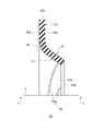
- Sectional drawing along an axis which shows schematic structure of the sealing device of embodiment Partially enlarged cross-sectional view of the upper side of the cross-section of FIG. Sectional drawing which shows partially the seal lip of the sealing device of embodiment
- FIG. 1 is a cross-sectional view along the axis x showing the schematic configuration of the sealing device 1 of the embodiment.
- FIG. 2 is a partially enlarged cross-sectional view of the upper side of the cross-section of the sealing device 1 of FIG.
- the direction of the arrow a on the axis x is defined as the outside
- the direction of the arrow b is defined as the inside.
- the inside is the internal space side of the member to which the sealing device 1 is attached, and is the space side (sealing object side) where the sealing object such as lubricant exists.
- the outside is the side opposite to the sealing object side, the side that prevents the sealing object from leaking, and is the atmosphere side.
- the direction away from the axis x (the direction of arrow c in FIGS. 1 and 2) is defined as the outer peripheral side, and the direction approaching the axis x ( , 2 in the direction of arrow d) is defined as the inner peripheral side.
- the sealing device 1 of the embodiment seals the annular space between the inner peripheral side member and the outer peripheral side member. As will be described later, in use, the sealing device 1 is attached to the annular space.
- the inner peripheral member is, for example, an output shaft of an electric motor.
- the outer peripheral member is, for example, an electric motor housing having a through hole through which the output shaft of the electric motor passes. Note that the inner peripheral member is not limited to a member that rotates about the axis x, and may be a member that reciprocates along the axis x.
- the sealing device 1 has a retaining ring 10, a sealing lip 20, and a conductive lip 30.
- the retaining ring 10 is made of metal and has an annular shape around the axis x.
- the sealing lip 20 is annular around the axis x.
- Conductive lip 30 is electrically conductive and annular about axis x. The seal lip 20 and the conductive lip 30 are fixed to the retaining ring 10 on the outer peripheral side.
- the seal lip 20 has a seal portion 21 .
- the seal portion 21 extends obliquely with respect to the axis x and has an end portion (inner peripheral end portion 20a) on the inner peripheral side.
- the conductive lip 30 has a contact portion 31 .
- the contact portion 31 extends obliquely with respect to the axis x and has an end portion (inner peripheral end portion 30a) on the inner peripheral side.
- the seal lip 20 and the conductive lip 30 are spaced apart in the direction of the axis x at least at the seal portion 21 and the contact portion 31 .
- the seal lip 20 has an inner peripheral surface 22 facing the inner peripheral side of the seal portion 21 .
- the inner peripheral surface 22 contacts the inner peripheral side member.
- the conductive lip 30 has an inner peripheral surface 32 facing the inner peripheral side of the contact portion 31 .
- the inner peripheral surface 32 contacts the inner peripheral side member.
- the retaining ring 10 has a receiving portion against which the seal lip 20 or the conductive lip 30 is pressed in the direction of the axis x.
- a sealing lip 20 and a conductive lip 30 are pressed against the retaining ring 10 in the direction of the axis x.
- the retaining ring 10 is made of metal and has an annular shape centered on the axis x.
- the retaining ring 10 is L-shaped in a cross section along the axis x (hereinafter also simply referred to as a “cross section”).
- the retaining ring 10 has, for example, a cylindrical portion 11 and a disc portion 12 .
- the cylindrical portion 11 has a cylindrical shape extending in the direction of the axis x.
- the disk portion 12 has a hollow disk shape extending from the outer (arrow a direction) end portion of the cylindrical portion 11 toward the inner peripheral side (arrow d direction).
- the disc portion 12 serves as a receiving portion. As will be described later, in the state of use, the cylindrical portion 11 is fitted and fixed to the inner peripheral surface of the through hole formed in the outer peripheral member.
- the seal lip 20 has an annular shape centered on the axis x.
- Seal lip 20 is made of an elastic material.
- the cross-sectional shape of the seal lip 20 has the same thickness along the extending direction between the inner peripheral side and the outer peripheral side.
- the seal lip 20 has a seal portion 21 , a fixed portion 23 and a connection portion 24 .
- the seal portion 21 is a portion on the inner peripheral side of the seal lip 20 .
- the fixed portion 23 is positioned on the outer peripheral side of the seal portion 21 .
- the fixed portion 23 extends in the radial direction and has an end portion (outer peripheral end portion 20b) on the outer peripheral side.
- the fixed portion 23 is connected to the seal portion 21 via the connection portion 24 .
- the connecting portion 24 connects the sealing portion 21 and the fixing portion 23 .
- the seal portion 21 extends obliquely with respect to the axis x so as to increase in diameter toward the outside (in the direction of arrow a) in the direction of the axis x.
- the seal portion 21 has the same thickness over the extending direction.
- thickness is the width
- the seal portion 21 has a truncated cone shape centered on the axis x.
- the fixed portion 23 extends parallel to the radial direction.
- the fixed portion 23 has the same thickness along the extending direction.
- the connecting portion 24 extends convexly outward such that the sealing portion 21 is located inside the fixing portion 23 .
- the connecting portion 24 has the same thickness along the extension direction.
- the inner peripheral surface 22 of the seal portion 21 contacts the inner peripheral side member.
- the contact portion 22a on the inner peripheral side of the imaginary line (l1) indicating the outer peripheral surface of the inner peripheral member in the use state shown in FIGS. 1 and 2 contacts the inner peripheral member.
- the contact portion 22a forms an annular surface having a width in the extending direction of the seal portion 21 from the inner peripheral end portion 20a.
- the fixed portion 23 receives an outward force in the direction of the axis x.
- the fixed portion 23 is specifically in the shape of a hollow disk centered on the axis x.
- the fixed portion 23 has a radial length corresponding to the disk portion 12 of the retaining ring 10, as shown in FIGS.
- the fixed portion 23 has a radial length that is slightly shorter than the radial length of the disk portion 12 of the retaining ring 10 . 1 and 2, the fixed portion 23 has a radial length corresponding to a fixed portion 33 of the conductive lip 30, which will be described later.
- the securing portion 23 has a radial length that is slightly less than the radial length of the securing portion 33 of the conductive lip 30 .
- the fixing portion 23 contacts the inner peripheral surface 11a of the cylindrical portion 11 at the outer peripheral end portion 20b.
- the fixed portion 23 does not have to contact the inner peripheral surface 11a of the cylindrical portion 11 at the outer peripheral end portion 20b.
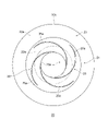
- a thread groove 25 is formed in the seal lip 20 as shown in FIGS.
- the thread groove 25 forms an airflow from the outside to the inside of the seal lip 20 as the inner peripheral member rotates during use. This causes a pumping action from the outside of the sealing lip 20 to the inside.
- the screw groove 25 is formed, for example, from four grooves 25a to form a four-thread screw.
- the groove 25 a is recessed inside from the surface of the seal lip 20 .
- the groove 25a extends in a direction corresponding to the rotational direction of the inner peripheral member.
- the thread groove 25 is not limited to forming a four-start thread, and the number of grooves forming the thread groove 25 is not limited to four.
- the thread groove 25 should just generate a pump action.
- the thread groove 25 may be formed from one groove 25a that forms a single thread, or may be formed from multiple grooves 25a that form another multiple thread.
- the thread groove 25 is formed on the inner peripheral surface 22 of the seal portion 21 .
- Each groove 25a crosses the contact portion 22a from the outside of the contact portion 22a and reaches the inner peripheral end portion 20a.
- the position of the screw groove 25 is not limited to this.
- each groove 25a does not have to reach the inner peripheral end 20a.
- each groove 25a may be formed only outside the contact portion 22a of the inner peripheral surface 22 and may not reach the contact portion 22a.
- the seal lip 20 may not have the thread groove 25 .
- the conductive lip 30 has an annular shape centered on the axis x, as shown in FIGS.
- Conductive lip 30 is formed from a material having electrical conductivity.
- Conductive lip 30 has a shape similar to sealing lip 20 .
- the cross-sectional shape of the conductive lip 30 has the same thickness along the extending direction between the inner peripheral side and the outer peripheral side.
- the conductive lip 30 has a contact portion 31 , a fixed portion 33 and a connecting portion 34 .
- the contact portion 31 is a portion on the inner peripheral side of the conductive lip 30 .
- the fixed portion 33 is positioned on the outer peripheral side of the contact portion 31 .
- the fixed portion 33 extends in the radial direction and has an end portion (outer peripheral end portion 30b) on the outer peripheral side.
- the fixed portion 33 is connected to the contact portion 31 via the connection portion 34 .
- the connection portion 34 connects the contact portion 31 and the fixed portion 33 .
- the contact portion 31 extends obliquely with respect to the axis x so as to increase in diameter toward the outside (in the direction of the arrow a) in the direction of the axis x.
- the contact portion 31 has the same thickness in the extending direction.
- thickness is the width
- the contact portion 31 has a truncated cone shape centered on the axis x.
- the fixed portion 33 extends parallel to the radial direction.
- the fixed portion 33 has the same thickness along the extending direction.
- the connecting portion 34 extends convexly outward such that the contact portion 31 is located inside the fixing portion 33 .
- the connecting portion 34 has the same thickness in the extending direction.
- the inner peripheral surface 32 of the contact portion 31 contacts the inner peripheral side member.
- the contact portion 32a on the inner peripheral side of the imaginary line (l1) indicating the outer peripheral surface of the inner peripheral member in the use state shown in FIGS. 1 and 2 contacts the inner peripheral member.
- the contact portion 32a forms an annular surface having a width in the extending direction of the contact portion 31 from the inner peripheral end portion 30a.
- the fixed portion 33 receives an outward force in the direction of the axis x.
- the fixed portion 33 is pressed against the disk portion 12 of the retaining ring 10 outward in the direction of the axis x.
- the fixing portion 33 is specifically in the shape of a hollow disk centered on the axis x.
- the fixed portion 33 has a radial length corresponding to the disk portion 12 of the retaining ring 10, as shown in FIGS.
- the fixed portion 33 has a radial length that is slightly longer than the radial length of the disk portion 12 of the retaining ring 10 .
- the fixed portion 33 contacts the inner peripheral surface 11a of the cylindrical portion 11 at the outer peripheral end portion 30b.
- the fixed portion 33 does not have to contact the inner peripheral surface 11a of the cylindrical portion 11 at the outer peripheral end portion 30b.
- the shape of the conductive lip 30 is similar to the shape of the seal lip 20. 1 and 2, the width of the contact portion 32a of the contact portion 31 is larger than the width of the contact portion 22a of the seal portion 21. As shown in FIG. The interference of the conductive lip 30 is larger than the interference of the seal lip 20. - ⁇ However, the relationship between the interference of the seal lip 20 and the interference of the conductive lip 30 is not limited to this.
- the seal lip 20 and the conductive lip 30 are fixed to the retaining ring 10 on the outer peripheral side.
- the sealing device 1 has a push ring 13 .
- a push ring 13 secures the sealing lip 20 and the conductive lip 30 to the retaining ring 10 .
- the push ring 13 is annular around the axis x.
- the push ring 13 can be fitted and fixed to the retaining ring 10 .
- the push ring 13 pushes the seal lip 20 and the conductive lip 30 outward in the direction of the axis x.
- the push ring 13 has, for example, an annular shape centered on the axis x.
- the push ring 13 has an L-shaped cross section.
- the push ring 13 has a cylindrical portion 13a and a push portion 13b.
- the cylindrical portion 13a has a cylindrical shape extending in the direction of the axis x.
- the pressing portion 13b has a hollow disk shape and extends from the outer end of the cylindrical portion 13a to the inner peripheral side.
- the cylindrical portion 13 a is fitted and fixed to the inner peripheral side of the cylindrical portion 11 of the retaining ring 10 .
- the pressing portion 13b contacts the fixed portion 23 of the seal lip 20 from the inner side in the direction of the axis x.
- the sealing device 1 has spacers 14 .
- the spacer 14 forms a space between the seal lip 20 and the conductive lip 30 in the direction of the axis x at the portion where the seal lip 20 and the conductive lip 30 and the retaining ring 10 are fixed.
- the spacer 14 is made of metal and has an annular shape around the axis x.
- the spacer 14 has, for example, a hollow disc shape centered on the axis x.
- the cross-sectional shape of the spacer 14 extends parallel to the radial direction, as shown in FIGS.
- the spacer 14 has a constant thickness along its extending direction.
- the spacer 14 has a radial length corresponding to the fixed portion 23 of the seal lip 20 and the fixed portion 33 of the conductive lip 30, as shown in FIGS.
- the spacer 14 has, for example, a radial length equivalent to the radial length of the fixed portion 23 of the seal lip 20 .
- the spacer 14 is sandwiched between the fixed portion 23 of the seal lip 20 and the fixed portion 33 of the conductive lip 30 in the direction of the axis x. Further, the spacer 14 contacts the inner peripheral surface 11a of the cylindrical portion 11 at the outer peripheral end portion 14a. Note that the spacer 14 does not have to contact the inner peripheral surface 11a of the cylindrical portion 11 at the outer peripheral end portion 14a.
- the seal lip 20 and the conductive lip 30 are sandwiched between the disk portion 12 of the retaining ring 10 and the pressing portion 13b of the pressing ring 13 in the direction of the axis x, and are attached to the retaining ring 10.
- the push ring 13 is press-fitted and fixed to the cylindrical portion 11 of the retaining ring 10 .
- a spacer 14 is sandwiched between the sealing lip 20 and the conductive lip 30 .
- the seal lip 20 and the conductive lip 30 are separated from each other in the direction of the axis x, and a space S is formed between the seal lip 20 and the conductive lip 30 .
- the fixing portion 23 of the seal lip 20 is pushed outward in the direction of the axis x by the pushing portion 13b of the push ring 13 .
- the fixed portion 33 of the conductive lip 30 is pushed outward in the direction of the axis x by the fixed portion 23 of the seal lip 20 via the spacer 14 .
- the fixed portion 33 of the conductive lip 30 is pressed outwardly in the direction of the axis x against the disk portion 12 of the retaining ring 10 .
- the seal lip 20 and the conductive lip 30 are sandwiched between the retaining ring 10 and the pressing ring 13 at the fixing portions 23 and 33 and fixed to the retaining ring 10 .
- the sealing lip 20 and the conductive lip 30 are fixed to the retaining ring 10 without using an adhesive.
- outer peripheral end portion 20b of the seal lip 20, the outer peripheral end portion 30b of the conductive lip 30, and the outer peripheral end portion 14a of the spacer 14 are in contact with the cylindrical portion 11 of the retaining ring 10.
- the outer peripheral end portion 20b of the seal lip 20 does not have to come into contact with the cylindrical portion 11 of the retaining ring 10 .
- the outer peripheral end portion 30b of the conductive lip 30 does not have to contact the cylindrical portion 11 of the retaining ring 10 .
- the outer peripheral end portion 14 a of the spacer 14 does not have to come into contact with the cylindrical portion 11 of the retaining ring 10 .
- the retaining ring 10 may have a support portion 15 as shown in FIGS.
- the support portion 15 protrudes from the inner end portion of the cylindrical portion 11 to the inner peripheral side.
- the support portion 15 is annular and contacts the inner end portion of the cylindrical portion 13a of the push ring 13 from the inside.
- the support portion 15 is formed by deforming the inner end portion of the cylindrical portion 11 toward the inner peripheral side.
- the spacer 14 is sandwiched between the fixed portion 23 of the seal lip 20 and the fixed portion 33 of the conductive lip 30.
- the seal lip 20 and the conductive lip 30 have similar shapes. Therefore, the space S between the seal lip 20 and the conductive lip 30 has a constant width along the extending direction between the inner peripheral side and the outer peripheral side.
- the space S has a spacing such that the seal portion 21 of the seal lip 20 and the contact portion 31 of the conductive lip 30 do not overlap in the radial direction in use.
- a conductive grease G may be provided in the space S.
- the conductive grease G may fill the entire space S or may be provided in a part of the space S.
- the seal lip 20 is made of either PTFE or rubber, for example.
- Conductive lip 30 is formed from a material having electrical conductivity.
- conductive lip 30 is formed from conductive PTFE, conductive fabric, and conductive rubber.
- the retaining ring 10 can be fitted into the annular gap between the outer peripheral side member and the inner peripheral side member to be attached. Also, the seal lip 20 can come into contact with the inner peripheral member. Therefore, it is possible to prevent leakage of the object to be sealed to the outside, and prevent foreign matter such as sand, muddy water, and dust from entering from the atmospheric side.
- An electrically conductive conductive lip 30 is contactable with the inner member. Also, the conductive lip 30 contacts the metal retaining ring 10 attached to the outer peripheral member. Therefore, the sealing device 1 forms a conducting path between the inner peripheral side member and the outer peripheral side member. Further, the outer surface 33 a of the fixing portion 33 of the conductive lip 30 contacts the disk portion 12 of the retaining ring 10 . An outer peripheral end portion 30 b of the conductive lip 30 contacts the cylindrical portion 11 of the retaining ring 10 . Therefore, the contact area between the conductive lip 30 and the retaining ring 10 is increased, and the conductivity of the conduction path between the inner peripheral side member and the outer peripheral side member is increased.
- a metal spacer 14 contacts the inner surface 33 b of the fixed portion 33 of the conductive lip 30 .
- Spacer 14 contacts cylindrical portion 11 of retaining ring 10 . Therefore, the contact area between the conductive lip 30 and the retaining ring 10 is increased, and the conductivity of the conduction path between the inner peripheral side member and the outer peripheral side member is increased.
- the connection between the conductive lip 30, the retaining ring 10 and the spacer 14 is fixed without using an adhesive. Therefore, the reduction in the contact area between the conductive lip 30 and the retaining ring 10 is suppressed, and the conductivity of the conduction path between the inner peripheral side member and the outer peripheral side member is increased.
- FIG. 5 is a partially enlarged sectional view of the sealing device 1 in use.
- a housing 50 to be attached has a shaft hole 51 which is a through hole.
- a shaft 52 is inserted into the shaft hole 51 .
- the sealing device 1 is mounted on the shaft 52 .
- the housing 50 is, for example, an electric motor housing.
- Shaft 52 is, for example, the output shaft of an electric motor.
- the sealing device 1 when the sealing device 1 is used, the sealing device 1 is press-fitted into the shaft hole 51 and fitted. Thus, the sealing device 1 is fixed to the housing 50 . More specifically, the retaining ring 10 is press-fitted into the shaft hole 51 . The cylindrical portion 11 of the retaining ring 10 is in close contact with the inner peripheral surface 51 a of the shaft hole 51 . Thereby, the space between the sealing device 1 and the shaft hole 51 is sealed. Further, the sealing device 1 is axially aligned with the shaft hole 51 by press-fitting the retaining ring 10 into the shaft hole 51 .
- the inner peripheral surface 22 of the seal portion 21 contacts the outer peripheral surface 52a of the shaft 52 and is elastically deformed. Then, the contact portion 22 a of the inner peripheral surface 22 contacts the outer peripheral surface 52 a of the shaft 52 .
- the seal lip 20 contacts the outer peripheral surface 52a of the shaft 52 so that the shaft 52 can slide.
- the seal lip 20 prevents the sealing object such as lubricating oil from leaking out beyond the sealing lip 20 from the side of the sealing object.
- the seal lip 20 prevents foreign matter from entering the interior from the outside.
- the seal lip 20 contacts the outer peripheral surface 52a of the shaft 52 at a contact portion 22a having a certain width in the direction of the axis x. Therefore, the sliding resistance between the seal lip 20 and the shaft 52 is reduced. Therefore, sliding heat generation between the seal lip 20 and the shaft 52 is suppressed, and the amount of heat generated is reduced. As a result, deterioration of the seal lip 20 due to sliding heat generation can be prevented, and deterioration of sealing performance can be prevented.
- the seal lip 20 is formed with a thread groove 25 that exerts a pump action. Therefore, even if an object to be sealed oozes out from the inside of the housing 50 beyond the seal lip 20 , the exuded object to be sealed can be returned to the inside from the outside of the housing 50 .
- the pump action also improves the sealing performance of the sealing device 1 .
- a layer of the object to be sealed is formed between the contact portion 22a of the seal lip 20 and the outer peripheral surface 52a of the shaft 52 by the pumping action. Thereby, the sliding resistance between the seal lip 20 and the shaft 52 is reduced, and the generation of sliding heat can be suppressed.
- the sealing device 1 heat generated by sliding between the seal lip 20 and the shaft 52 can be suppressed also by the action of the thread groove 25 . As a result, deterioration of the seal lip 20 due to sliding heat generation can be prevented, and deterioration of sealing performance can be prevented.
- the seal lip 20 is made of PTFE, the heat resistance of the seal lip 20 is enhanced. Also, the coefficient of friction of the seal lip 20 is reduced, and the sliding resistance is reduced. Therefore, it is possible to suppress the generation of heat generated by sliding, prevent deterioration of the seal lip 20 due to heat generated by sliding, and prevent deterioration of sealing performance.
- the inner peripheral surface 32 of the contact portion 31 contacts the outer peripheral surface 52a of the shaft 52 and is elastically deformed. Then, the contact portion 32 a of the inner peripheral surface 32 contacts the outer peripheral surface 52 a of the shaft 52 .
- the sealing device 1 when the sealing device 1 is in use, the conductive lip 30 contacts the outer peripheral surface 52a of the shaft 52 so that the shaft 52 can slide. Also, the retaining ring 10 contacts the housing 50 . The sealing device 1 forms a conducting path between the shaft 52 and the housing 50 . As a result, leakage current generated in the electric motor is discharged from the shaft 52 to the housing 50 through the conducting path. This can prevent the occurrence of noise due to leakage current.
- the conductive lip 30 contacts the outer peripheral surface 52a of the shaft 52 at a contact portion 32a having a certain width in the direction of the axis x. Therefore, the sliding resistance between the conductive lip 30 and the shaft 52 is reduced. Therefore, sliding heat generation between the conductive lip 30 and the shaft 52 is suppressed, and the amount of heat generated is reduced. As a result, deterioration of the conductive lip 30 due to sliding heat generation can be prevented, and deterioration of conductive performance can be prevented. Also, the conductive lip 30 contacts the outer peripheral surface 52a of the shaft 52 at a contact portion 32a having a certain width in the direction of the axis x. Therefore, the cross-sectional area of the conduction path is increased, and the conductivity between the conductive lip 30 and the shaft 52 is increased.
- the heat resistance of the conductive lip 30 is enhanced. Also, the coefficient of friction of the conductive lip 30 is reduced, and the sliding resistance is reduced. Therefore, it is possible to suppress the generation of heat generated by sliding, prevent deterioration of the conductive lip 30 due to heat generated by sliding, and prevent deterioration of the conductive performance.
- the conductive lip 30 is made of conductive PTFE, it is possible to prevent deterioration of the conductive lip 30 due to sliding heat generation and to prevent deterioration of the sealing performance of the conductive lip 30 .
- the outer peripheral end portion 30b of the conductive lip 30 contacts the cylindrical portion 11 of the retaining ring 10.
- the metal spacer 14 contacts the inner side surface 33 b of the fixed portion 33 .
- Spacer 14 contacts cylindrical portion 11 of retaining ring 10 . Therefore, the cross-sectional area of the conductive path between the conductive lip 30 and the retaining ring 10 is increased.
- the conductive lip 30, the retaining ring 10, and the spacer 14 are fixed without using an adhesive, and the cross-sectional area of the conductive path between the conductive lip 30 and the retaining ring 10 is prevented from decreasing. This makes the conducting path between the shaft 52 and the housing 50 highly conductive.
- a conductive grease G is provided in the space S between the seal lip 20 and the conductive lip 30 facing each other in the direction of the axis x. Therefore, the cross-sectional area of the conduction path of the sealing device 1 is increased, and the conductivity of the conduction path between the shaft 52 and the housing 50 is increased. A portion of the space S is sandwiched between the contact portion 31 of the conductive lip 30 and the seal portion 21 of the seal lip 20 in the radial direction. Therefore, the conductive grease G is easily held in the space S. Therefore, the conductive grease G works for a long time.
- the seal lip 20 and the conductive lip 30 are similar to each other and face each other in the direction of the axis x. Therefore, the size of the sealing device 1 can be reduced, and the mounting space for the sealing device 1 can be reduced.
- the sealing lip 20 and the conductive lip 30 are members different from each other. Therefore, the sealing performance and electrical conductivity are improved, and sliding heat generation for preventing deterioration of the sealing performance and electrical conductivity can be effectively suppressed.
- the seal lip 20 is provided on the side of the object to be sealed, and the conductive lip 30 is provided on the atmosphere side. This improves sealing performance and electrical conductivity.
- the sealing device 1 of this embodiment According to the sealing device 1 of this embodiment, deterioration due to heat generation can be prevented. This can prevent deterioration of the sealing performance. In addition, it is possible to prevent deterioration of the conductive performance and prevent deterioration of the electromagnetic noise suppressing action.
- the sealing device 1 of the embodiment has been described above, the sealing device of the present disclosure is not limited to the sealing device 1 described above, and includes all aspects included in the concept and claims of the present disclosure. Moreover, each configuration may be selectively combined as appropriate so as to achieve at least part of the above-described problems and effects. For example, the shape, material, arrangement, size, etc. of each component in the above embodiments may be changed as appropriate according to the specific usage of the present disclosure.
- the seal portion 21 of the seal lip 20 and the contact portion 31 of the conductive lip 30 extend diagonally in the same direction, but they may extend diagonally in different directions.
- the sealing lip 20 may be provided on the atmosphere side, and the conductive lip 30 may be provided on the sealed object side.
- the sealing device 1 of the embodiment has a spacer 14 as a member different from the seal lip 20 and the conductive lip 30 .
- the sealing lip 20 or the conducting lip 30 may integrally form the spacer 14 at the fixed portions 23, 33 respectively.
- the fixing portion 33 of the conductive lip 30 may have a portion having a shape similar to that of the spacer 14 .
Landscapes
- Engineering & Computer Science (AREA)
- General Engineering & Computer Science (AREA)
- Mechanical Engineering (AREA)
- Physics & Mathematics (AREA)
- Fluid Mechanics (AREA)
- Power Engineering (AREA)
- Sealing With Elastic Sealing Lips (AREA)
- Sealing Devices (AREA)
- Motor Or Generator Frames (AREA)
Priority Applications (6)
| Application Number | Priority Date | Filing Date | Title |
|---|---|---|---|
| JP2022578431A JP7437539B2 (ja) | 2021-01-27 | 2022-01-26 | 密封装置 |
| US18/265,610 US20240035573A1 (en) | 2021-01-27 | 2022-01-26 | Sealing device |
| KR1020237022681A KR20230114288A (ko) | 2021-01-27 | 2022-01-26 | 밀봉 장치 |
| EP22745895.7A EP4287783A4 (en) | 2021-01-27 | 2022-01-26 | SEALING DEVICE |
| CN202280008106.9A CN116746284A (zh) | 2021-01-27 | 2022-01-26 | 密封装置 |
| JP2024018684A JP2024045492A (ja) | 2021-01-27 | 2024-02-09 | 密封装置 |
Applications Claiming Priority (2)
| Application Number | Priority Date | Filing Date | Title |
|---|---|---|---|
| JP2021011531 | 2021-01-27 | ||
| JP2021-011531 | 2021-01-27 |
Publications (1)
| Publication Number | Publication Date |
|---|---|
| WO2022163675A1 true WO2022163675A1 (ja) | 2022-08-04 |
Family
ID=82653595
Family Applications (1)
| Application Number | Title | Priority Date | Filing Date |
|---|---|---|---|
| PCT/JP2022/002760 Ceased WO2022163675A1 (ja) | 2021-01-27 | 2022-01-26 | 密封装置 |
Country Status (6)
| Country | Link |
|---|---|
| US (1) | US20240035573A1 (https=) |
| EP (1) | EP4287783A4 (https=) |
| JP (2) | JP7437539B2 (https=) |
| KR (1) | KR20230114288A (https=) |
| CN (1) | CN116746284A (https=) |
| WO (1) | WO2022163675A1 (https=) |
Cited By (3)
| Publication number | Priority date | Publication date | Assignee | Title |
|---|---|---|---|---|
| CN116677604A (zh) * | 2023-05-30 | 2023-09-01 | 华涧新能源科技(上海)有限公司 | 一种气封结构以及氢气循环泵 |
| WO2024190361A1 (ja) * | 2023-03-10 | 2024-09-19 | Nok株式会社 | 密封装置 |
| WO2025068798A1 (en) * | 2023-09-28 | 2025-04-03 | Troy Lance Timm | Shaft grounding assembly |
Families Citing this family (5)
| Publication number | Priority date | Publication date | Assignee | Title |
|---|---|---|---|---|
| WO2022163675A1 (ja) * | 2021-01-27 | 2022-08-04 | Nok株式会社 | 密封装置 |
| GB202409063D0 (en) * | 2024-06-25 | 2024-08-07 | Rolls Royce Plc | Seal structure for a gas turbine engine |
| JP7707468B1 (ja) * | 2025-03-25 | 2025-07-14 | Nok株式会社 | 導電リング |
| JP7707467B1 (ja) * | 2025-03-25 | 2025-07-14 | Nok株式会社 | 導電リング |
| JP7707469B1 (ja) * | 2025-03-25 | 2025-07-14 | Nok株式会社 | 導電リング |
Citations (7)
| Publication number | Priority date | Publication date | Assignee | Title |
|---|---|---|---|---|
| JPH11218229A (ja) * | 1998-01-30 | 1999-08-10 | Toyota Autom Loom Works Ltd | オイルシール及びエンジン |
| JP2015014296A (ja) | 2013-07-03 | 2015-01-22 | 内山工業株式会社 | 密封装置 |
| JP2015207534A (ja) | 2014-04-23 | 2015-11-19 | 本田技研工業株式会社 | 車両用動力伝達装置 |
| WO2019131899A1 (ja) * | 2017-12-27 | 2019-07-04 | Nok株式会社 | 密封装置 |
| JP2019173773A (ja) * | 2018-03-27 | 2019-10-10 | キーパー株式会社 | 密封装置 |
| US20200103029A1 (en) * | 2018-10-01 | 2020-04-02 | Carl Freudenberg Kg | Sealing element |
| JP2020523531A (ja) * | 2017-06-12 | 2020-08-06 | ガーロック・シーリング・テクノロジーズ・エルエルシー | 多層ptfeラジアルリップシール |
Family Cites Families (24)
| Publication number | Priority date | Publication date | Assignee | Title |
|---|---|---|---|---|
| IT1053388B (it) * | 1975-02-20 | 1981-08-31 | Garlock Inc | Perfezionamento nei dispositivi di tenuta per alberi ruotanti |
| US5595697A (en) * | 1990-01-25 | 1997-01-21 | Nok Corporation | Method of manufacturing a sealing device |
| EP0578755B1 (en) * | 1991-04-04 | 1995-09-06 | W.L. Gore & Associates, Inc. | Electrically conductive gasket materials |
| JP2843280B2 (ja) * | 1995-09-29 | 1999-01-06 | アイシン精機株式会社 | ウォータポンプ |
| JPH1163241A (ja) * | 1997-08-27 | 1999-03-05 | Mitsubishi Cable Ind Ltd | 回転用シール |
| JP3875824B2 (ja) * | 2000-03-17 | 2007-01-31 | イーグル工業株式会社 | リップ型シール |
| JP3890925B2 (ja) * | 2001-07-06 | 2007-03-07 | 株式会社日立製作所 | シール機構を備えた高圧燃料ポンプ及びそのシール機構 |
| US6830641B2 (en) * | 2001-08-13 | 2004-12-14 | Saint-Gobain Performance Plastics Corporation | Method of making a seal formed from polymer laminated metallic constructions |
| JP3876171B2 (ja) * | 2002-03-08 | 2007-01-31 | 株式会社小松製作所 | オイルシール |
| DE10314923B4 (de) * | 2003-04-01 | 2007-03-22 | Carl Freudenberg Kg | Einrichtung zur Erfassung einer Leckage |
| US8235391B2 (en) * | 2010-03-17 | 2012-08-07 | Federal-Mogul Corporation | Radial shaft seal assembly with lubrication retention and debris exclusion feature and method of construction thereof |
| JP6081179B2 (ja) * | 2012-12-14 | 2017-02-15 | Nok株式会社 | 密封装置 |
| JP2014139451A (ja) * | 2013-01-21 | 2014-07-31 | Nok Corp | 密封装置 |
| DE102013000982B4 (de) * | 2013-01-22 | 2015-10-29 | Carl Freudenberg Kg | Dichtring und Dichtungsanordnung damit |
| DE102014210129A1 (de) * | 2014-05-27 | 2015-12-03 | Aktiebolaget Skf | Dichtungsvorrichtung und Verfahren zum Abdichten in einem flüssigen Medium |
| DE102014010269B4 (de) * | 2014-07-11 | 2020-06-18 | Carl Freudenberg Kg | Vorschaltdichtung, Vorschaltdichtungsanordnung und Dichtring, umfassend die Vorschaltdichtung |
| DE202016009162U1 (de) * | 2016-03-03 | 2023-06-29 | Kaco Gmbh + Co. Kg | Wellenerdungsring |
| DE102016207672A1 (de) * | 2016-05-04 | 2017-11-09 | Bayerische Motoren Werke Aktiengesellschaft | Dichtungssystem für eine Welle |
| DE102017004061B4 (de) * | 2017-04-27 | 2019-01-31 | Carl Freudenberg Kg | Dichtung |
| DE102018115732A1 (de) * | 2018-06-29 | 2020-01-02 | Schaeffler Technologies AG & Co. KG | Wälzlager mit integrierter Stromableitfunktion |
| CN113474568B (zh) * | 2019-05-08 | 2024-01-05 | Nok株式会社 | 密封装置 |
| CN111894991A (zh) * | 2020-07-30 | 2020-11-06 | 舍弗勒技术股份两合公司 | 导电密封环和轴承组件 |
| WO2022163675A1 (ja) * | 2021-01-27 | 2022-08-04 | Nok株式会社 | 密封装置 |
| DE102022104415A1 (de) * | 2021-05-03 | 2022-11-03 | BRUSS Sealing Systems GmbH | Radialwellendichtring |
-
2022
- 2022-01-26 WO PCT/JP2022/002760 patent/WO2022163675A1/ja not_active Ceased
- 2022-01-26 JP JP2022578431A patent/JP7437539B2/ja active Active
- 2022-01-26 US US18/265,610 patent/US20240035573A1/en active Pending
- 2022-01-26 CN CN202280008106.9A patent/CN116746284A/zh active Pending
- 2022-01-26 EP EP22745895.7A patent/EP4287783A4/en active Pending
- 2022-01-26 KR KR1020237022681A patent/KR20230114288A/ko active Pending
-
2024
- 2024-02-09 JP JP2024018684A patent/JP2024045492A/ja active Pending
Patent Citations (7)
| Publication number | Priority date | Publication date | Assignee | Title |
|---|---|---|---|---|
| JPH11218229A (ja) * | 1998-01-30 | 1999-08-10 | Toyota Autom Loom Works Ltd | オイルシール及びエンジン |
| JP2015014296A (ja) | 2013-07-03 | 2015-01-22 | 内山工業株式会社 | 密封装置 |
| JP2015207534A (ja) | 2014-04-23 | 2015-11-19 | 本田技研工業株式会社 | 車両用動力伝達装置 |
| JP2020523531A (ja) * | 2017-06-12 | 2020-08-06 | ガーロック・シーリング・テクノロジーズ・エルエルシー | 多層ptfeラジアルリップシール |
| WO2019131899A1 (ja) * | 2017-12-27 | 2019-07-04 | Nok株式会社 | 密封装置 |
| JP2019173773A (ja) * | 2018-03-27 | 2019-10-10 | キーパー株式会社 | 密封装置 |
| US20200103029A1 (en) * | 2018-10-01 | 2020-04-02 | Carl Freudenberg Kg | Sealing element |
Non-Patent Citations (1)
| Title |
|---|
| See also references of EP4287783A4 |
Cited By (5)
| Publication number | Priority date | Publication date | Assignee | Title |
|---|---|---|---|---|
| WO2024190361A1 (ja) * | 2023-03-10 | 2024-09-19 | Nok株式会社 | 密封装置 |
| JPWO2024190361A1 (https=) * | 2023-03-10 | 2024-09-19 | ||
| JP7760092B2 (ja) | 2023-03-10 | 2025-10-24 | Nok株式会社 | 密封装置 |
| CN116677604A (zh) * | 2023-05-30 | 2023-09-01 | 华涧新能源科技(上海)有限公司 | 一种气封结构以及氢气循环泵 |
| WO2025068798A1 (en) * | 2023-09-28 | 2025-04-03 | Troy Lance Timm | Shaft grounding assembly |
Also Published As
| Publication number | Publication date |
|---|---|
| JPWO2022163675A1 (https=) | 2022-08-04 |
| EP4287783A4 (en) | 2024-12-04 |
| JP2024045492A (ja) | 2024-04-02 |
| CN116746284A (zh) | 2023-09-12 |
| EP4287783A1 (en) | 2023-12-06 |
| KR20230114288A (ko) | 2023-08-01 |
| JP7437539B2 (ja) | 2024-02-22 |
| US20240035573A1 (en) | 2024-02-01 |
Similar Documents
| Publication | Publication Date | Title |
|---|---|---|
| WO2022163675A1 (ja) | 密封装置 | |
| JP7214807B2 (ja) | 密封装置 | |
| JP7360454B2 (ja) | 密封装置 | |
| CN115777047B (zh) | 密封装置 | |
| JP6967155B2 (ja) | 密封装置 | |
| JP2024175009A (ja) | 導電性密封装置 | |
| CN103534905B (zh) | 用于电机的止推垫片 | |
| CN110005815A (zh) | 密封装置、轴组件和轴承 | |
| CN106030135A (zh) | 带密封件的球轴承 | |
| CN111895095A (zh) | 密封组件 | |
| KR102536974B1 (ko) | 씰링 구조가 개선된 휠베어링 | |
| KR101366143B1 (ko) | 휠 베어링의 씰링 장치 | |
| US20260039078A1 (en) | Conductive structural body and conduction method | |
| KR20250144431A (ko) | 밀봉 장치 | |
| CN114688169A (zh) | 密封组件及密封结构 |
Legal Events
| Date | Code | Title | Description |
|---|---|---|---|
| 121 | Ep: the epo has been informed by wipo that ep was designated in this application |
Ref document number: 22745895 Country of ref document: EP Kind code of ref document: A1 |
|
| WWE | Wipo information: entry into national phase |
Ref document number: 18265610 Country of ref document: US |
|
| WWE | Wipo information: entry into national phase |
Ref document number: 202280008106.9 Country of ref document: CN |
|
| ENP | Entry into the national phase |
Ref document number: 20237022681 Country of ref document: KR Kind code of ref document: A |
|
| ENP | Entry into the national phase |
Ref document number: 2022578431 Country of ref document: JP Kind code of ref document: A |
|
| WWE | Wipo information: entry into national phase |
Ref document number: 2022745895 Country of ref document: EP |
|
| NENP | Non-entry into the national phase |
Ref country code: DE |
|
| ENP | Entry into the national phase |
Ref document number: 2022745895 Country of ref document: EP Effective date: 20230828 |