WO2022162989A1 - 電動機の制御装置 - Google Patents
電動機の制御装置 Download PDFInfo
- Publication number
- WO2022162989A1 WO2022162989A1 PCT/JP2021/032028 JP2021032028W WO2022162989A1 WO 2022162989 A1 WO2022162989 A1 WO 2022162989A1 JP 2021032028 W JP2021032028 W JP 2021032028W WO 2022162989 A1 WO2022162989 A1 WO 2022162989A1
- Authority
- WO
- WIPO (PCT)
- Prior art keywords
- phase
- voltage
- harmonic
- current
- rotor
- Prior art date
- Legal status (The legal status is an assumption and is not a legal conclusion. Google has not performed a legal analysis and makes no representation as to the accuracy of the status listed.)
- Ceased
Links
Images

Classifications
-
- H—ELECTRICITY
- H02—GENERATION; CONVERSION OR DISTRIBUTION OF ELECTRIC POWER
- H02P—CONTROL OR REGULATION OF ELECTRIC MOTORS, ELECTRIC GENERATORS OR DYNAMO-ELECTRIC CONVERTERS; CONTROLLING TRANSFORMERS, REACTORS OR CHOKE COILS
- H02P27/00—Arrangements or methods for the control of AC motors characterised by the kind of supply voltage
- H02P27/04—Arrangements or methods for the control of AC motors characterised by the kind of supply voltage using variable-frequency supply voltage, e.g. inverter or converter supply voltage
- H02P27/06—Arrangements or methods for the control of AC motors characterised by the kind of supply voltage using variable-frequency supply voltage, e.g. inverter or converter supply voltage using DC to AC converters or inverters
- H02P27/08—Arrangements or methods for the control of AC motors characterised by the kind of supply voltage using variable-frequency supply voltage, e.g. inverter or converter supply voltage using DC to AC converters or inverters with pulse width modulation
-
- H—ELECTRICITY
- H02—GENERATION; CONVERSION OR DISTRIBUTION OF ELECTRIC POWER
- H02P—CONTROL OR REGULATION OF ELECTRIC MOTORS, ELECTRIC GENERATORS OR DYNAMO-ELECTRIC CONVERTERS; CONTROLLING TRANSFORMERS, REACTORS OR CHOKE COILS
- H02P21/00—Arrangements or methods for the control of electric machines by vector control, e.g. by control of field orientation
- H02P21/05—Arrangements or methods for the control of electric machines by vector control, e.g. by control of field orientation specially adapted for damping motor oscillations, e.g. for reducing hunting
-
- H—ELECTRICITY
- H02—GENERATION; CONVERSION OR DISTRIBUTION OF ELECTRIC POWER
- H02P—CONTROL OR REGULATION OF ELECTRIC MOTORS, ELECTRIC GENERATORS OR DYNAMO-ELECTRIC CONVERTERS; CONTROLLING TRANSFORMERS, REACTORS OR CHOKE COILS
- H02P2207/00—Indexing scheme relating to controlling arrangements characterised by the type of motor
- H02P2207/05—Synchronous machines, e.g. with permanent magnets or DC excitation
Definitions
- the present invention relates to an electric motor control device.
- a permanent magnet synchronous motor is designed so that the magnetic flux produced by the stator and the magnetic flux produced by the rotor are sine waves.
- harmonics synchronized with the rotor position (the phase of the rotor as seen from the stator) are superimposed on the interlinking magnetic flux due to the structure of the stator teeth, the arrangement of the rotor magnets, and the like. This distorts the interlinkage magnetic flux, which causes motor noise and torque pulsation.
- an electric motor is mounted on an electric vehicle, the drivability and marketability of the vehicle deteriorate.
- the distortion of the interlinking magnetic flux appears as the distortion of the induced voltage.
- the harmonic voltage contained in the induced voltage is generated in synchronization with the phase of the rotor. Therefore, distortion can be suppressed by superimposing a harmonic voltage of opposite phase based on the phase of the rotor by an inverter (controller), and noise and torque pulsation generated from the motor can be suppressed.
- an inverter controller
- noise and torque pulsation generated from the motor can be suppressed.
- Patent Literature 1 The invention described in Patent Literature 1 is a technique that calculates an anti-phase harmonic voltage based on the phase of the rotor and superimposes it on the voltage command value on the two-phase fixed coordinates.
- PWM phase lag compensation for superimposed harmonic voltages in the controller Therefore, it is difficult to correctly superimpose the harmonic voltages at high motor speeds.
- the problem to be solved by the present invention is to superimpose the anti-phase harmonic voltage superimposed by the controller in order to suppress the noise and torque pulsation generated from the electric motor without phase delay.
- a control apparatus for an electric motor includes: a harmonic voltage calculation unit for calculating a harmonic voltage to be added to a fundamental wave voltage command value on a two-phase rotating coordinate system synchronized with a rotor phase; a harmonic phase delay compensating section for compensating for a phase delay during calculation in the section based on the harmonic order of the harmonic voltage and the electrical angle frequency of the fundamental voltage.
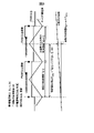
- FIG. 3 is a processing block diagram illustrating conventional processing of the controller 104; It is a figure which shows the principle of PWM phase lag compensation.
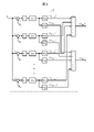
- 3 is a processing block diagram of a harmonic superimposing unit 211; FIG. It is a simulation waveform in conventional processing of the controller 104 .
- FIG. 3 is a processing block diagram for explaining the processing of the controller 104 according to the present invention; It is a simulation waveform in the processing of the controller 104 according to the present invention.
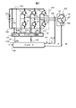
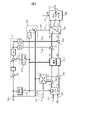
- FIG. 1 is a diagram showing a schematic circuit configuration of a power converter.
- the power conversion device for the electric motor 102 is mainly composed of an inverter 101, a battery 103, a controller 104, and the like.
- Inverter 101 is a three-phase voltage source two-level inverter.
- the electric motor 102 is connected to the drive mechanism of the electric vehicle system, and the electric motor 102 rotates to propel the vehicle.
- the electric motor 102 of this embodiment is an AC electric motor, which is a three-phase interior permanent magnet type synchronous motor (IPMSM).
- the electric motor 102 interacts with a magnetic flux generated by a permanent magnet provided in a rotor (not shown) and a magnetic field generated by currents iu, iv, and iw flowing through three-phase windings 105, 106, and 107 fixed to the armature. It works by iu, iv, and iw are the U-phase current, V-phase current, and W-phase current, respectively.
- a permanent magnet synchronous motor is used for explanation, but the present invention can also be applied to other synchronous motors such as wound field synchronous motors.
- the electric motor 102 is equipped with a magnetic pole position sensor 108 .
- the magnetic pole position sensor 108 has a function of detecting the magnetic pole position of the rotor of the electric motor 102 as a phase with respect to the stator.
- Magnetic pole position sensor 108 outputs rotor phase 109 ( ⁇ ), which is input to controller 104 .
- the processing in the controller 104 for the rotor phase 109( ⁇ ) will be described later with reference to FIG.
- the magnetic pole position sensor 108 can be configured by a resolver, rotary encoder, absolute encoder, or the like.
- Current sensor 110 detects currents flowing through windings 105, 106 and 107, and based on this, U-phase current sensor signal 111 (signal indicating current iu), V-phase current sensor signal 112 (signal indicating current iv), W A phase current sensor signal 113 (a signal indicating the current iw) is output and input to the controller 104 . Processing of current sensor signals 111, 112, and 113 in controller 104 will also be described later with reference to FIG.
- the inverter 101 includes switching elements 114, 115, 116, 117, 118, 119 and freewheeling diodes 120, 121, 122, 123, 124, 125.
- the switching elements 114 to 119 of this embodiment are Si-IGBTs and include gate terminals, collector terminals, and emitter terminals. Freewheeling diodes 120-125 are connected between respective collector and emitter terminals of switching elements 114-119. The freewheeling diodes 120-125 allow current to flow through the freewheeling diodes 120-125 when the potential of the collector terminals of the switching elements 114-119 is higher than that of the emitter terminals of the switching elements 114-119, thereby preventing a high reverse voltage from being applied to the switching elements 114-119.
- the inverter circuit is not limited to the combination of the Si-IGBT and the free wheel diode, and may be configured by other semiconductor elements.
- the ON/OFF switching of the switching elements 114-119 is performed by gate drive signals 126, 127, 128, 129, 130, 131 connected to the gate terminals of the respective switching elements 114-119.
- a gate signal 132 that is the basis of each of the gate drive signals 126 to 131 is generated by the controller 104 and output to the gate drive circuit 135 .
- the gate drive circuit 135 converts the gate signal 132 into a potential required to turn on and off the switching elements 114, 115, 116, 117, 118, and 119 to generate the gate drive signals 126, 127, 128, 129, and 130. , 131.
- Generation of gate signal 132 in controller 104 will be described later with reference to FIG.
- the emitter terminal of the switching element 114 and the collector terminal of the switching element 115 are connected to each other, and the connection point is connected to the winding 105 to flow the current iu.
- the emitter terminal of switching element 116 and the collector terminal of switching element 117 are connected to each other, and the connection point is connected to winding 106 to allow current iv to flow.
- the emitter terminal of switching element 118 and the collector terminal of switching element 119 are connected to each other, and the connection point is connected to winding 107 to allow current iw to flow.
- the collector terminals of the switching elements 114 , 116 and 118 are connected together and connected to the high potential DC wiring 133 .
- the emitter terminals of the switching elements 115 , 117 , 119 are connected to each other and connected to the low-potential DC wiring 134 .
- the controller 104 Based on the generated gate signal 132, the controller 104 turns on and off the switching elements 114, 115, 116, 117, 118, and 119 at appropriate timings, and the current iu flowing through the windings 105, 106, and 107 is , iv, and iw to realize rotation control of the electric motor 102 .
- the gating signal 132 is in the form of a PWM (Pulse Width Modulated) signal such that the currents iu, iv, iw are sinusoidal signals that are 120 degrees out of phase with each other.
- the voltage sensor 136 is connected to the high-potential DC wiring 133 and the low-potential DC wiring 134 and detects the potential difference between them. Since the potential difference between the high-potential DC wiring 133 and the low-potential DC wiring 134 is normally a high voltage of 100 V or more, the voltage sensor 136 generates a DC voltage sensor signal 137 (Vdc) converted to a low voltage detectable by the controller 104. and input to the controller 104 .
- Vdc DC voltage sensor signal 137
- a smoothing capacitor 138 included in the inverter 101 is connected between the high potential DC wiring 133 and the low potential DC wiring 134 .
- the smoothing capacitor 138 functions to suppress pulsation of the DC voltage generated by the switching operations of the switching elements 114-119.
- the high potential side terminal of the battery 103 and the high potential DC wiring 133 are connected to the battery 103, and the low potential side terminal of the battery 103 and the low potential DC wiring 134 are connected. Thereby, it functions as a DC power supply that supplies power to the inverter 101 and the electric motor 102 .
- the controller 104 receives a torque command 139 (T*) given from a vehicle host controller such as an ECU (Electronic Control Unit).
- the controller 104 performs torque control of the electric motor 102 based on this torque command 139 (T*).
- the rotor temperature of the electric motor 102 is input to the controller 104 .
- the rotor temperature is desirably detected by a temperature sensor, but may be configured to use a temperature estimated by a known method.
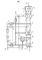
- FIG. 2 is a processing block diagram illustrating conventional processing of the controller 104.
- the processing blocks of the controller 104 include a current command calculation unit 201, a three-phase two-phase conversion unit 202, a current control unit 203, a two-phase three-phase conversion unit 204, a speed calculation unit 205, and a PWM gate control signal generation unit ( control signal generator) 206 , deviation calculator 207 , deviation calculator 208 , PWM phase lag compensator 209 , and harmonic superimposer 211 .
- the current command calculator 201, the three-phase two-phase converter 202, the current controller 203, the two-phase three-phase converter 204, the deviation calculator 207, and the deviation calculator 208 form a three-phase voltage command value generator.
- the controller 104 controls the rotation by supplying three-phase currents iu, iv, and iw to the electric motor 102. Inside the controller 104, the rotor phase represented by the d-axis and the q-axis is changed from the three-phase fixed coordinates. A so-called current vector control method is used in which processing is performed in a coordinate system converted into synchronized two-phase rotating coordinates.
- a current command calculation unit 201 calculates a d-axis current command value id* and a q-axis current command value iq*.
- a torque command 139 (T*), a rotational angular velocity ⁇ , and a DC voltage sensor signal 137 (Vdc) are input to a current command calculation unit 201, and a d-axis current command value id* and a q-axis current command value iq* are obtained. calculated.
- the rotational angular velocity ⁇ is calculated by the speed calculator 205 based on the rotor phase 109 ( ⁇ ).
- a three-phase to two-phase conversion unit 202 performs coordinate conversion of the current sensor signals 111 (iu), 112 (iv), and 113 (iw) to the d-axis and the q-axis based on the information of the rotor phase 109 ( ⁇ ). to output the d-axis detection current id and the q-axis detection current iq.
- a deviation calculator 207 calculates the deviation between the d-axis current command value id* output from the current command calculation unit 201 and the d-axis detection current id output from the three-phase to two-phase conversion unit 202, and calculates the d-axis current deviation. ⁇ id is output to current control section 203 .
- a deviation calculator 208 computes the deviation between the q-axis current command value iq* output from the current command computation unit 201 and the q-axis detection current iq output from the three-phase to two-phase conversion unit 202 to obtain a q-axis current deviation ⁇ iq. is output to the current control unit 203 .
- the current control unit 203 performs feedback control so that the d-axis current deviation ⁇ id and the q-axis current deviation ⁇ iq that indicate the deviation between the command value that is the target value and the measured value that is the output value become zero, and the output value is A d-axis voltage command Vd* and a q-axis voltage command Vq*, which are voltage commands for updating, are calculated and output.
- Feedback control in the current control unit 203 is performed by PI control, for example.
- the adder 212 adds Vd* and Vdhrm* output from the harmonic superimposer 211, which will be described later, and outputs a new d-axis voltage command value Vd**.
- Adder 213 adds Vq* and Vqhrm* output from harmonic superimposer 211, which will be described later, and outputs a new q-axis voltage command value Vq**.
- Vd** and Vq** are input to a two-to-three-phase converter 204, which calculates and outputs three-phase voltage command values Vu*, Vv*, and Vw* based on the corrected rotor phase 210 ( ⁇ delay). do.
- the corrected rotor phase 210 ( ⁇ delay) input to the two-to-three-phase converter 204 is calculated by the PWM phase delay compensator 209 as shown in Equations (1) and (2).
- ⁇ delay ⁇ + ⁇ Tdelay (1)
- Tdelay Ts[n]+0.5Ts[n+1] (2)
- Tdelay is the control delay time
- Ts[n] is the current control cycle (carrier cycle)
- Ts[n+1] is the control cycle for the next interrupt.
- PWM phase lag compensation which is a technology related to the present invention, will be described.
- the coordinate conversion is performed by estimating the rotor phase advanced during the control delay time. It is a function to perform. The reason why the control delay time occurs and the method of compensation will be explained below.
- FIG. 3 shows an example of the relationship between the operation timing of the controller 4 (phase current and rotor phase detection and current control, PWM duty update), rotor phase, and control delay time when the horizontal axis is time. .
- the detection timing of the DC voltage sensor signal 137 (Vdc) used for PWM duty calculation is omitted.
- the PWM duty update timing is delayed by the current control period Ts[n] with respect to the detection of the phase current and rotor phase.
- the PWM duty is constant during the period of the control cycle Ts[n+1] at the time of the next interrupt, and it is necessary to set the average PWM duty during this period. Therefore, the control delay time Tdelay from the detection of the phase current and rotor phase to the update of the PWM duty is expressed by Equation (2) described above.
- the rotor phase difference ⁇ diff progressing during Tdelay can be calculated as shown in Equation (3).
- a PWM gate control signal generator (control signal generator) 206 calculates a PWM duty from the three-phase voltage command values Vu*, Vv*, Vw* and Vdc. By comparing the PWM duty with a carrier wave (not shown), six gate signals 132 that are PWM signals are generated and output to the gate drive circuit 135 .
- FIG. 4 is a processing block diagram of the harmonic superimposing unit 211.
- a d-axis harmonic voltage command value Vdhrm* and a q-axis harmonic voltage command value Vqhrm* are output by the calculations of equations (4) and (5).
- Vdhrm* ⁇ (Adi ⁇ SIN(ni( ⁇ + ⁇ i))
- Vqhrm* ⁇ (Aqi ⁇ SIN(ni( ⁇ + ⁇ i)) (5)
- Adi is the d-axis harmonic voltage amplitude
- Aqi is the q-axis harmonic voltage amplitude
- ni is the harmonic order
- ⁇ i is the harmonic voltage phase.
- Vdhrm* and Vqhrm* are signals obtained by synthesizing harmonic voltages of a plurality of orders, and the harmonic voltage to be superimposed is selected according to the harmonic voltage contained in the induced voltage of the motor.
- the harmonic voltage contained in the induced voltage is mainly 6n ⁇ 1 order on fixed coordinates (n is a natural number excluding 0, in the case of three-phase equilibrium), and 6n on rotating coordinates synchronized with the rotor phase. Next. Therefore, the harmonic to be superimposed should be selected to be the 6nth order.
- Adi, Aqi and ⁇ i are set so as to cancel the harmonic voltage superimposed on the induced voltage. These values may not be constant values, but may be changed using a lookup table or the like depending on torque, current, number of revolutions, and the like.
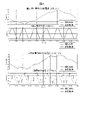
- FIG. 5 shows waveforms (simulation waveforms) of the U-phase current iu and the q-axis harmonic voltage Vqhrm when the harmonic voltage is superimposed only on the q-axis in the conventional processing of the controller 104 shown in FIG.
- the dotted line represents the waveform in the ideal state
- the dotted line represents the waveform in the conventional control.
- two results of 300 rpm and 3000 rpm are compared.
- the ideal state shows the analytical results in a continuous system.
- simulation was performed using a model that takes into consideration the delay due to discrete control without simulating the PWM control of the inverter.
- the control period is 10 kHz.
- the conventional control q-axis harmonic voltage lags behind the ideal state, but there is no significant lag. Therefore, it can be seen that there is no large difference in the U-phase current between the ideal state and the conventional control.
- the q-axis harmonic voltage under conventional control lags significantly behind the ideal state, so it can be seen that there is a large difference in the U-phase current as well.
- the harmonic voltage to be superimposed cannot be correctly superimposed as the motor speed increases.
- noise and torque pulsation generated from the electric motor cannot be suppressed, and depending on the magnitude of the lag phase, the noise and torque pulsation may be amplified.
- FIG. 6 is a processing block diagram explaining the processing of the controller 104 according to the present invention.
- FIG. 6 has a configuration in which a harmonic phase delay compensator 601 is added to FIG.
- Vdhrm* ⁇ (Adi ⁇ SIN(ni( ⁇ + ⁇ Tdelay+ ⁇ i)) (7)
- Vqhrm* ⁇ (Aqi ⁇ SIN(ni( ⁇ + ⁇ Tdelay+ ⁇ i)) (8)
- the above formula can be transformed as follows using formula (1).
- Vdhrm* ⁇ (Adi ⁇ SIN(ni( ⁇ delay+ ⁇ i)) (9)
- Vqhrm* ⁇ (Aqi ⁇ SIN(ni( ⁇ delay+ ⁇ i)) (10)
- phase delay compensation for harmonics can be realized by replacing the input ⁇ in FIG.
- Vdhrm* and Vqhrm* calculated as described above are added to the dq-axis voltage commands on the rotating coordinates, respectively, and converted into three-phase voltage command values by the two-to-three-phase converter 204 .
- phase delay compensation by the harmonic phase delay compensator 601 and phase delay compensation by the two-to-three-phase converter 204 and the PWM phase delay compensator 209 are doubled with respect to the superimposed harmonic voltage command. This principle will be explained below.
- Vdhrm Ad ⁇ SIN(n( ⁇ + ⁇ )) (11)
- Vqhrm Aq ⁇ SIN(n( ⁇ + ⁇ )) (12)
- Phase voltages Vu, Vv, and Vw after harmonic superimposition can be expressed as follows.
- phase lag compensation by the harmonic phase lag compensator 601 and phase lag compensation by the two-to-three phase converter 204 and the PWM phase lag compensator 209 are required.
- FIG. 7 shows waveforms (simulated waveforms) of the U-phase current iu and the q-axis harmonic voltage Vqhrm when the harmonic voltage is superimposed only on the q-axis in the processing of the present invention by the controller 104 shown in FIG. ing. Simulation conditions are the same as those shown in FIG.
- the q-axis harmonic voltage of the control of the present invention does not lag behind the ideal state. Therefore, although there is a difference in the U-phase current due to the discretization error, it can be seen that there is no large difference between the ideal state and the control of the present invention.
- the motor control apparatus includes: a harmonic voltage calculation unit for calculating a harmonic voltage to be added to a fundamental voltage command value on a two-phase rotating coordinate system synchronized with a rotor phase; a harmonic phase delay compensator for compensating a phase delay during calculation in the wave voltage calculator based on the harmonic order of the harmonic voltage and the electrical angle frequency of the fundamental voltage.
- 101 inverter, 102: electric motor, 103: battery, 104: controller, 105 to 107: three-phase winding, 108: magnetic pole position sensor, 109: rotor phase, 110: current sensor, 111: U-phase current sensor signal, 112: V-phase current sensor signal, 113: W-phase current sensor signal, 114-119: switching element, 120-125: IGBT, 126-131: gate drive signal, 132: gate signal, 133: high potential DC wiring, 134 : low potential DC wiring, 135: gate drive circuit, 136: voltage sensor, 137: DC voltage sensor signal, 138: smoothing capacitor, 139: torque command, 201: current command calculation unit, 202: three-phase to two-phase conversion unit, 203: current control unit, 204: two-phase three-phase conversion unit, 205: speed calculation unit, 206: PWM gate control signal generation unit (control signal generation unit), 207: deviation calculator, 208: deviation calculator, 209: PWM phase lag compensator, 211
Landscapes
- Engineering & Computer Science (AREA)
- Power Engineering (AREA)
- Control Of Ac Motors In General (AREA)
Abstract
Description
θdelay=θ+ω×Tdelay ・・・(1)
Tdelay=Ts[n]+0.5Ts[n+1] ・・・(2)
ただし、式(1)、式(2)において、Tdelayは制御遅れ時間、Ts[n]は現在の制御周期(キャリア周期)、Ts[n+1]は次回割り込み時の制御周期である。
検出した回転子位相θにθdiffを加算することで、PWM duty更新時の回転子位相θdelayを式(1)のように推定できる。以上がPWM位相遅れ補償の原理である。
Vdhrm*=Σ(Adi×SIN(ni(θ+Φi)) ・・・(4)
Vqhrm*=Σ(Aqi×SIN(ni(θ+Φi)) ・・・(5)
ただし、式(4)、式(5)において、Adiはd軸高調波電圧振幅、Aqiはq軸高調波電圧振幅、niは高調波次数、Φiは高調波電圧位相である。また、iは1~mの整数である。Vdhrm*とVqhrm*は複数次数の高調波電圧を合成した信号となっており、電動機の誘起電圧に含まれる高調波電圧に応じて、重畳する高調波電圧を選択する。また、誘起電圧に含まれる高調波電圧は、主に固定座標上で6n±1次(nは0を除く自然数、三相平衡の場合)であり、回転子位相に同期した回転座標上では6n次となる。従って、重畳する高調波は6n次を選択すればよい。
θdiffn=n×ω×Tdelay ・・・(6)
高調波位相遅れ補償部601は、重畳する高調波の位相をθdiffnだけ進めることで、高調波に対する位相遅れを補償している。また、式(4)、(5)を高調波に対する位相遅れ補償を考慮して表すと下記となる。
Vdhrm*=Σ(Adi×SIN(ni(θ+ω×Tdelay+Φi)) ・・・(7)
Vqhrm*=Σ(Aqi×SIN(ni(θ+ω×Tdelay+Φi)) ・・・(8)
上記式は(1)式を用いて下記のように変形できる。
Vdhrm*=Σ(Adi×SIN(ni(θdelay+Φi)) ・・・(9)
Vqhrm*=Σ(Aqi×SIN(ni(θdelay+Φi)) ・・・(10)
(9)、(10)式より、実際の実装では図4における入力θを、PWM位相遅れ補償器209の出力θdelayに置き換えることで、高調波に対する位相遅れ補償を実現できる。
Vdhrm=Ad×SIN(n(θ+Φ)) ・・・(11)
Vqhrm=Aq×SIN(n(θ+Φ)) ・・・(12)
高調波重畳後の相電圧Vu,Vv、Vwは以下のように表せる。
Vu=Ad×SIN(n(θ+Φ))×COSθ - Aq×SIN(n(θ+Φ))×SINθ ・・・(13)
Vv=Ad×SIN(n(θ+Φ))×COS(θ-2π/3) - Aq×SIN(n(θ+Φ))×SIN(θ-2π/3) ・・・(14)
Vw=Ad×SIN(n(θ+Φ))×COS(θ+2π/3)-Aq×SIN(n(θ+Φ))×SIN(θ+2π/3) ・・・(15)
式(13)において、Ad×SIN(n(θ+Φ))やAq×SIN(n(θ+Φ))は重畳する高調波を表し、それらの後ろの項は座標変換の項を表している。式(14)、(15)においても同様である。高調波計算と座標変換に用いるθは、インバータの電圧が反映されるときのθを使用して計算する必要がある。すなわちそれぞれの計算に対し位相遅れ補償が必要となる。
Claims (2)
- 基本波電圧指令値に加算する高調波電圧を回転子位相に同期した二相回転座標系上で演算する高調波電圧演算部と、
前記高調波電圧演算部における演算時の位相遅れを前記高調波電圧の高調波次数と基本波電圧の電気角周波数とに基づいて補償する高調波位相遅れ補償部と、を備えた電動機の制御装置。 - 請求項1に記載された電動機の制御装置であって、
前記高調波電圧演算部によって演算された高調波電圧を回転子位相に同期した二相回転座標系上で前記基本波電圧指令値に加算する電動機の制御装置。
Priority Applications (4)
| Application Number | Priority Date | Filing Date | Title |
|---|---|---|---|
| JP2022578030A JP7385776B2 (ja) | 2021-01-29 | 2021-08-31 | 電動機の制御装置 |
| DE112021006189.5T DE112021006189T5 (de) | 2021-01-29 | 2021-08-31 | Steuerungsvorrichtung für einen elektromotor |
| US18/261,863 US12348168B2 (en) | 2021-01-29 | 2021-08-31 | Control device for electric motor |
| CN202180091892.9A CN116802991A (zh) | 2021-01-29 | 2021-08-31 | 电动机的控制装置 |
Applications Claiming Priority (2)
| Application Number | Priority Date | Filing Date | Title |
|---|---|---|---|
| JP2021-012640 | 2021-01-29 | ||
| JP2021012640 | 2021-01-29 |
Publications (1)
| Publication Number | Publication Date |
|---|---|
| WO2022162989A1 true WO2022162989A1 (ja) | 2022-08-04 |
Family
ID=82654299
Family Applications (1)
| Application Number | Title | Priority Date | Filing Date |
|---|---|---|---|
| PCT/JP2021/032028 Ceased WO2022162989A1 (ja) | 2021-01-29 | 2021-08-31 | 電動機の制御装置 |
Country Status (5)
| Country | Link |
|---|---|
| US (1) | US12348168B2 (ja) |
| JP (1) | JP7385776B2 (ja) |
| CN (1) | CN116802991A (ja) |
| DE (1) | DE112021006189T5 (ja) |
| WO (1) | WO2022162989A1 (ja) |
Citations (4)
| Publication number | Priority date | Publication date | Assignee | Title |
|---|---|---|---|---|
| JP2007006645A (ja) * | 2005-06-24 | 2007-01-11 | Toyota Motor Corp | 交流電圧出力装置およびそれを備えたハイブリッド自動車 |
| JP2016032407A (ja) * | 2014-07-30 | 2016-03-07 | 株式会社デンソー | 回転電機の制御装置 |
| JP2016082662A (ja) * | 2014-10-15 | 2016-05-16 | ダイキン工業株式会社 | 電力変換器制御装置 |
| WO2017064946A1 (ja) * | 2015-10-16 | 2017-04-20 | 日本精工株式会社 | モータ制御装置及びそれを搭載した電動パワーステアリング装置 |
Family Cites Families (7)
| Publication number | Priority date | Publication date | Assignee | Title |
|---|---|---|---|---|
| JP4234359B2 (ja) | 2002-06-27 | 2009-03-04 | オークマ株式会社 | 同期電動機の制御装置 |
| CN1206784C (zh) * | 2002-09-06 | 2005-06-15 | 清华大学 | 有源滤波器谐波电流检测的延迟时间的补偿方法及系统 |
| WO2004055967A1 (ja) * | 2002-10-17 | 2004-07-01 | Denso Corporation | 交流回転電機の磁気騒音低減方法、それを用いるモータ制御装置及び交流回転電機装置 |
| JP4117554B2 (ja) * | 2003-08-06 | 2008-07-16 | 株式会社デンソー | モータ制御装置 |
| US9419553B2 (en) | 2014-07-25 | 2016-08-16 | Denso Corporation | Apparatus for controlling rotary machine |
| CN104899398A (zh) * | 2015-06-23 | 2015-09-09 | 广州供电局有限公司 | 硬件在环仿真系统中信号延时补偿方法与系统 |
| CN107645164A (zh) * | 2016-07-22 | 2018-01-30 | 刘铮 | 一种新型有源电力滤波器选择性谐波补偿方法 |
-
2021
- 2021-08-31 DE DE112021006189.5T patent/DE112021006189T5/de active Pending
- 2021-08-31 JP JP2022578030A patent/JP7385776B2/ja active Active
- 2021-08-31 CN CN202180091892.9A patent/CN116802991A/zh active Pending
- 2021-08-31 US US18/261,863 patent/US12348168B2/en active Active
- 2021-08-31 WO PCT/JP2021/032028 patent/WO2022162989A1/ja not_active Ceased
Patent Citations (4)
| Publication number | Priority date | Publication date | Assignee | Title |
|---|---|---|---|---|
| JP2007006645A (ja) * | 2005-06-24 | 2007-01-11 | Toyota Motor Corp | 交流電圧出力装置およびそれを備えたハイブリッド自動車 |
| JP2016032407A (ja) * | 2014-07-30 | 2016-03-07 | 株式会社デンソー | 回転電機の制御装置 |
| JP2016082662A (ja) * | 2014-10-15 | 2016-05-16 | ダイキン工業株式会社 | 電力変換器制御装置 |
| WO2017064946A1 (ja) * | 2015-10-16 | 2017-04-20 | 日本精工株式会社 | モータ制御装置及びそれを搭載した電動パワーステアリング装置 |
Also Published As
| Publication number | Publication date |
|---|---|
| CN116802991A (zh) | 2023-09-22 |
| US12348168B2 (en) | 2025-07-01 |
| JPWO2022162989A1 (ja) | 2022-08-04 |
| DE112021006189T5 (de) | 2023-09-14 |
| JP7385776B2 (ja) | 2023-11-22 |
| US20240305233A1 (en) | 2024-09-12 |
Similar Documents
| Publication | Publication Date | Title |
|---|---|---|
| JP6617500B2 (ja) | 電動パワーステアリング制御方法、電動パワーステアリング制御装置、電動パワーステアリング装置および車両 | |
| CN101809857B (zh) | 旋转电机的控制装置 | |
| JP4961292B2 (ja) | モータ制御装置 | |
| JP4019842B2 (ja) | モータ制御装置 | |
| US9479106B2 (en) | Apparatus for controlling rotary machine | |
| US9112436B2 (en) | System for controlling controlled variable of rotary machine | |
| CN114208020B (zh) | 交流旋转电机的控制装置及电动助力转向装置 | |
| JPWO2019008676A1 (ja) | インバータ装置、及び、電動パワーステアリング装置 | |
| JP5514660B2 (ja) | 負荷制御装置 | |
| JPWO2016117115A1 (ja) | 交流回転機の制御装置 | |
| CN111034013B (zh) | 三相同步电动机的控制装置和使用其的电动助力转向装置 | |
| US11309817B2 (en) | Control device of rotating machine, and control device of electric vehicle | |
| JP2010068581A (ja) | 電動機駆動装置 | |
| JP2011062000A (ja) | 交流モータの制御装置 | |
| JP6116449B2 (ja) | 電動機駆動制御装置 | |
| JP7385776B2 (ja) | 電動機の制御装置 | |
| JP2023032879A (ja) | モータユニットの制御方法及び制御装置 | |
| JP5376218B2 (ja) | モータ制御装置 | |
| JP7267457B2 (ja) | 電力変換装置 | |
| JP2003274688A (ja) | インバータ制御方法およびその装置 | |
| JP2019161705A (ja) | 同期電動機の位置センサレス制御装置 | |
| JP2026007199A (ja) | 電動コンプレッサのモータ制御装置 | |
| HK1144501B (en) | Controller of rotary electric machine | |
| JP2010088264A (ja) | 電動機の磁極位置推定装置 |
Legal Events
| Date | Code | Title | Description |
|---|---|---|---|
| 121 | Ep: the epo has been informed by wipo that ep was designated in this application |
Ref document number: 21922997 Country of ref document: EP Kind code of ref document: A1 |
|
| ENP | Entry into the national phase |
Ref document number: 2022578030 Country of ref document: JP Kind code of ref document: A |
|
| WWE | Wipo information: entry into national phase |
Ref document number: 18261863 Country of ref document: US |
|
| WWE | Wipo information: entry into national phase |
Ref document number: 202180091892.9 Country of ref document: CN Ref document number: 112021006189 Country of ref document: DE |
|
| 122 | Ep: pct application non-entry in european phase |
Ref document number: 21922997 Country of ref document: EP Kind code of ref document: A1 |
|
| WWG | Wipo information: grant in national office |
Ref document number: 18261863 Country of ref document: US |