WO2022162720A1 - 制御装置、電力変換装置、モータ駆動装置及び冷凍サイクル適用機器 - Google Patents
制御装置、電力変換装置、モータ駆動装置及び冷凍サイクル適用機器 Download PDFInfo
- Publication number
- WO2022162720A1 WO2022162720A1 PCT/JP2021/002562 JP2021002562W WO2022162720A1 WO 2022162720 A1 WO2022162720 A1 WO 2022162720A1 JP 2021002562 W JP2021002562 W JP 2021002562W WO 2022162720 A1 WO2022162720 A1 WO 2022162720A1
- Authority
- WO
- WIPO (PCT)
- Prior art keywords
- compensation command
- control device
- voltage
- torque pulsation
- frequency
- Prior art date
- Legal status (The legal status is an assumption and is not a legal conclusion. Google has not performed a legal analysis and makes no representation as to the accuracy of the status listed.)
- Ceased
Links
Images


Classifications
-
- H—ELECTRICITY
- H02—GENERATION; CONVERSION OR DISTRIBUTION OF ELECTRIC POWER
- H02P—CONTROL OR REGULATION OF ELECTRIC MOTORS, ELECTRIC GENERATORS OR DYNAMO-ELECTRIC CONVERTERS; CONTROLLING TRANSFORMERS, REACTORS OR CHOKE COILS
- H02P6/00—Arrangements for controlling synchronous motors or other dynamo-electric motors using electronic commutation dependent on the rotor position; Electronic commutators therefor
- H02P6/10—Arrangements for controlling torque ripple, e.g. providing reduced torque ripple
-
- H—ELECTRICITY
- H02—GENERATION; CONVERSION OR DISTRIBUTION OF ELECTRIC POWER
- H02P—CONTROL OR REGULATION OF ELECTRIC MOTORS, ELECTRIC GENERATORS OR DYNAMO-ELECTRIC CONVERTERS; CONTROLLING TRANSFORMERS, REACTORS OR CHOKE COILS
- H02P23/00—Arrangements or methods for the control of AC motors characterised by a control method other than vector control
- H02P23/04—Arrangements or methods for the control of AC motors characterised by a control method other than vector control specially adapted for damping motor oscillations, e.g. for reducing hunting
-
- H—ELECTRICITY
- H02—GENERATION; CONVERSION OR DISTRIBUTION OF ELECTRIC POWER
- H02P—CONTROL OR REGULATION OF ELECTRIC MOTORS, ELECTRIC GENERATORS OR DYNAMO-ELECTRIC CONVERTERS; CONTROLLING TRANSFORMERS, REACTORS OR CHOKE COILS
- H02P27/00—Arrangements or methods for the control of AC motors characterised by the kind of supply voltage
- H02P27/04—Arrangements or methods for the control of AC motors characterised by the kind of supply voltage using variable-frequency supply voltage, e.g. inverter or converter supply voltage
- H02P27/06—Arrangements or methods for the control of AC motors characterised by the kind of supply voltage using variable-frequency supply voltage, e.g. inverter or converter supply voltage using DC to AC converters or inverters
-
- H—ELECTRICITY
- H02—GENERATION; CONVERSION OR DISTRIBUTION OF ELECTRIC POWER
- H02P—CONTROL OR REGULATION OF ELECTRIC MOTORS, ELECTRIC GENERATORS OR DYNAMO-ELECTRIC CONVERTERS; CONTROLLING TRANSFORMERS, REACTORS OR CHOKE COILS
- H02P6/00—Arrangements for controlling synchronous motors or other dynamo-electric motors using electronic commutation dependent on the rotor position; Electronic commutators therefor
- H02P6/14—Electronic commutators
- H02P6/16—Circuit arrangements for detecting position
- H02P6/18—Circuit arrangements for detecting position without separate position detecting elements
Definitions
- the present disclosure relates to a control device that controls a power conversion device having a smoothing capacitor, a power conversion device, a motor drive device, and a refrigeration cycle application device.
- a power conversion device includes a converter that converts an AC voltage output from an AC power source into a DC voltage, a smoothing capacitor that smoothes the output voltage of the converter, and a DC voltage that is output via the smoothing capacitor and converts it into an AC voltage. and an inverter for applying to the load. That is, the power conversion device has a smoothing capacitor between the converter and the inverter for smoothing the output voltage of the converter.
- Patent Document 1 describes a power converter for driving a compressor.
- this type of power converter when the DC voltage applied to the inverter oscillates, or when suppressing fluctuations in load torque, an oscillating component is superimposed on the current flowing through the inverter. If the value of this vibration component and the rotation speed of the motor interact with each other, an unintended vibration component may occur. This vibration component causes the motor to hum.
- Patent Document 1 suppresses the generation of the beat sound
- the motor cannot be driven at a rotation speed at which the beat sound is generated.
- this constraint limits the performance of the motor and the load.
- the present disclosure has been made in view of the above, and an object of the present disclosure is to obtain a control device that can suppress the generation of unintended vibration components that cause beat noise while eliminating restrictions on the rotation speed of the motor and the load.
- the control device is a control device that controls the operation of a power conversion device that includes a converter, a smoothing capacitor, and an inverter.
- the converter rectifies the power supply voltage, which is the voltage of the AC power supply.
- the smoothing capacitor smoothes the rectified voltage output by the converter.
- the inverter converts the DC voltage smoothed by the smoothing capacitor into AC voltage for the motor.
- the control device includes first to third computing units.
- the first computation unit computes a voltage command including a first compensation command for reducing a first torque ripple that pulsates at twice the frequency of the power supply voltage.
- the second computation unit computes a second compensation command for reducing a second torque pulsation that pulsates at the rotation frequency of the motor.
- the third computing section computes a third compensation command for reducing a third torque pulsation generated by the first torque pulsation and the second torque pulsation.
- control device it is possible to suppress the occurrence of unintended vibration components that cause beat noise while eliminating restrictions on the rotation speed of the motor and load.
- FIG. 1 is a diagram showing a configuration example of a power conversion device including a control device according to Embodiment 1;
- FIG. 1 is a block diagram showing a configuration example of a control device according to Embodiment 1;
- FIG. 11 is a diagram showing simulation results of a configuration that does not have a beat component compensation command calculation unit according to Embodiment 1;
- FIG. 10 is a diagram showing a simulation result of the configuration having the beat component compensation command calculation section according to Embodiment 1;
- FIG. 2 is a block diagram showing an example of a hardware configuration that implements the functions of the control device according to Embodiment 1;
- FIG. 4 is a block diagram showing another example of a hardware configuration that implements the functions of the control device according to Embodiment 1;
- FIG. 4 is a block diagram showing a configuration example of a control device according to Embodiment 2;
- FIG. 10 is a diagram showing a first configuration example of a beat component compensation command calculator according to Embodiment 2;
- FIG. 10 is a diagram showing a second configuration example of the beat component compensation command calculator according to the second embodiment;
- FIG. 11 is a block diagram showing a configuration example of a control device according to Embodiment 3;
- a control device, a power conversion device, a motor drive device, and a refrigeration cycle application device according to an embodiment of the present disclosure will be described below in detail with reference to the accompanying drawings.
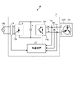
- FIG. 1 is a diagram showing a configuration example of a power conversion device 1 including a control device 2 according to Embodiment 1.
- the power converter 1 is connected to an AC power supply 100 and a compressor 120 .
- Compressor 120 is an example of a load that has periodic load torque fluctuations.
- Compressor 120 has motor 110 .
- the power converter 1 converts the power supply voltage applied from the AC power supply 100 into an AC voltage having a desired amplitude and phase, and applies the AC voltage to the motor 110 .
- the power conversion device 1 includes a control device 2, a converter 10, a smoothing capacitor 12, an inverter 14, a voltage detector 16, and current detectors 18u, 18v and 18w.
- Control device 2 controls the operation of inverter 14 .
- a motor driving device 50 is configured by the power conversion device 1 and the motor 110 included in the compressor 120 .
- the voltage detector 16 detects the power supply voltage applied from the AC power supply 100 to the converter 10 . A detected value of the voltage detector 16 is input to the control device 2 .
- the converter 10 rectifies the voltage output from the AC power supply 100 .
- the converter 10 is configured using a plurality of bridge-connected rectifying elements 10a. Note that the arrangement and connection of the rectifying element 10a in the converter 10 are known, and the description thereof is omitted here.
- the converter 10 may have a rectifying function as well as a boosting function for boosting the rectified voltage.
- a converter having a boosting function may be configured with one or more switching elements, or a plurality of switching elements in which a transistor element and a diode are connected in antiparallel, in addition to the rectifying element 10a or in place of the rectifying element 10a. can. Note that the arrangement and connection of switching elements in a converter having a boosting function are well known, and descriptions thereof will be omitted here.
- the rectified voltage rectified by the converter 10 is applied to the smoothing capacitor 12 .
- the smoothing capacitor 12 is connected to the output terminal of the converter 10 .
- Smoothing capacitor 12 smoothes the rectified voltage applied from converter 10 .
- Examples of the smoothing capacitor 12 include an electric field capacitor and a film capacitor.
- the inverter 14 is connected across the smoothing capacitor 12 .
- Inverter 14 converts the DC voltage smoothed by smoothing capacitor 12 into AC voltage for compressor 120 and applies it to motor 110 of compressor 120 .
- the inverter 14 is configured using a plurality of switching elements 14a in which transistor elements and diodes are connected in antiparallel. The arrangement and connection of the switching elements 14a in the inverter 14 are known, and the description thereof is omitted here.
- Electric wiring connecting the inverter 14 and the motor 110 is provided with current detectors 18u, 18v, and 18w.
- Current detectors 18u, 18v, and 18w detect currents corresponding to one phase of each of three-phase motor currents iu, iv, and iw output from inverter 14, respectively.
- Each detection value of the current detectors 18u, 18v, 18w is input to the control device 2.
- a compressor 120 is a load having a motor 110 for driving the compressor.
- the motor 110 rotates according to the amplitude and phase of the second AC voltage applied from the inverter 14 and performs compression operation.
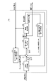
- FIG. 2 is a block diagram showing a configuration example of the control device 2 according to Embodiment 1.
- the control device 2 includes a speed controller 21, an adder/subtractor 22, a voltage command calculator 23, a speed estimator 24, a torque ripple compensation command calculator 25, and a beat component compensation command calculator. a portion 26;
- the control device 2 receives a detected voltage, which is a detected value of the power supply voltage, and a detected current, which is a detected value of the motor currents iu, iv, and iw.
- the speed command is generated by a higher control device (not shown) or generated inside the control device 2 . Note that FIG.
- the control device 2 shows a configuration in which a speed command is generated by a higher-level control device.
- the control device 2 generates and outputs a voltage command to be given to the inverter 14 so that the inverter 14 outputs an AC voltage having a desired amplitude and phase.
- the speed control unit 21 calculates a basic torque command that makes the rotational speed of the motor 110 match the speed command and outputs it to the adder/subtractor 22 .
- Speed control by a general Proportional Integral Differential (PID) controller or a general Proportional Integral (PI) controller can be applied to the calculation of the basic torque command.
- PID Proportional Integral Differential
- PI Proportional Integral
- a controller other than the PID controller or the PI controller may be used as long as desired control performance can be obtained.
- Torque pulsation compensation command calculation unit 25 calculates a torque pulsation compensation command for compensating for periodic torque pulsations that occur when motor 110 is rotated and compressor 120 is operated, and outputs the torque pulsation compensation command to adder/subtractor 22 .
- the configuration of the torque pulsation compensation command calculator 25 is known, and detailed description thereof will be omitted here. A specific configuration is disclosed in Japanese Patent No. 6537725, for example.
- the torque ripple compensation command generated by the torque ripple compensation command calculator 25 is added to or subtracted from the basic torque command in the adder/subtractor 22 .
- the output of the adder/subtractor 22 may contain beat components, which are unintended frequency components. Therefore, the beat component compensation command calculation section 26 calculates a beat component compensation command for compensating for this beat component and outputs it to the adder/subtractor 22 .
- the adder/subtractor 22 further adds or subtracts the beat component compensation command, and outputs the calculated value to the voltage command calculator 23 as a torque command. The details of the control performed by the beat component compensation command calculator 26 will be described later.
- the voltage command calculation unit 23 calculates a voltage command that causes the output torque of the motor 110 to match the torque command, and outputs the voltage command to the speed estimation unit 24 .
- the configuration of the voltage command calculation unit 23 is known, and detailed description thereof will be omitted here.
- Japanese Patent No. 6537725 it is described as a "torque control section".
- the voltage command generated by the voltage command calculation unit 23 includes a compensation command for reducing torque pulsation that pulsates at twice the frequency of the power supply voltage.
- first torque pulsation the torque pulsation that pulsates at twice the frequency of the power supply voltage
- second torque pulsation the periodic torque pulsation that occurs when the compressor 120 described above is operated.
- the beat component described above is also a component of torque pulsation generated by the first torque pulsation and the second torque pulsation, so this is appropriately described as “third torque pulsation”.
- the compensation command for reducing the first torque ripple is appropriately described as “first compensation command”
- the torque ripple compensation command for reducing the second torque ripple is appropriately described as “second compensation command”
- a beat component compensation command for reducing a beat component which is a component having the same frequency as the frequency component of the third torque pulsation, will be appropriately referred to as a “third compensation command”.
- smoothing capacitor 12 sufficiently smoothes the DC voltage output from converter 10 .
- the inverter current flowing through the inverter 14 has a small pulsating current value, but a large pulsating current flows through the smoothing capacitor 12 . Therefore, the capacity of the smoothing capacitor 12 is a factor that accelerates deterioration of the smoothing capacitor 12 . Therefore, in Embodiment 1, the capacitance of the smoothing capacitor 12 is made as small as possible while allowing the pulsation of the inverter current.
- the voltage command calculator 23 Since the pulsation of the inverter current causes the first torque pulsation in the load, the voltage command calculator 23 generates a first compensation command for reducing the first torque pulsation.
- the first compensation command is included in the voltage command and output.
- the speed estimator 24 calculates an estimated speed and an estimated acceleration based on the voltage command and the detected current.
- the estimated speed is an estimated value of the rotational speed of the motor 110 and the estimated acceleration is an estimated value of the rotational acceleration of the motor 110 .
- a case in which a PI controller and an integrator are connected in series is known for calculating the estimated velocity and the estimated acceleration, and detailed description thereof will be omitted here.
- the torque ripple compensation command which is the second compensation command, can be formulated by the following equation (1) at a certain amplitude component
- angular frequency ⁇ 1 in the above equation ( 1 ) is an angular frequency expressed in mechanical angles.
- the beat component described above is generated by the angular frequency ⁇ 1 of the compressor 120 and the angular frequency ⁇ s of the power supply voltage.
- the theoretical calculation formula is as follows.
- the third and fourth terms of the above equation (6) are the above-described unintended frequency components, and beat components are generated based on these.
- this beat component is represented by I beat_comp , the following equation (7) is obtained.
- the beat component can be calculated if the angular frequency ⁇ s and the expression (1) are known.
- the beat component can be canceled by subtracting the calculated value of the beat component from I qref in the above equation (2). It should be noted that the beat noise reduction effect can be obtained even with only one of the two terms in the above equation (7).
- Iqrip is a torque ripple compensation command. Therefore, the beat component compensation command calculation unit 26 estimates the beat component based on the torque ripple compensation command and the detected value of the power supply voltage, and generates the beat component compensation command based on the estimated beat component. 22 compensates for the base torque. As shown in the above equation (7), the beat component compensation command is calculated based on the amplitude component and phase component of the torque ripple compensation command and the phase component of the detected value of the power supply voltage.
- FIG. 3 is a diagram showing a simulation result of a configuration without the beat component compensation command calculation section 26 according to Embodiment 1.
- FIG. 4 is a diagram showing a simulation result of a configuration including the beat component compensation command calculation section 26 according to the first embodiment. 3 and 4, the horizontal axis represents frequency, and the vertical axis represents amplitude of each frequency component on the horizontal axis.
- the control device includes the first to third computing units.
- the first computation unit computes a voltage command including a first compensation command for reducing a first torque ripple that pulsates at twice the frequency of the power supply voltage.
- the second computation unit computes a second compensation command for reducing a second torque pulsation that pulsates at the rotation frequency of the motor.
- the third computing section computes a third compensation command for reducing a third torque pulsation generated by the first torque pulsation and the second torque pulsation.
- the third compensation command reduces unintended inclusion of beat components that may be included in the input signal of the control section that performs torque control. As a result, it is possible to suppress the occurrence of unintended vibration components that cause beat noise in the motor and load. By suppressing the occurrence of unintended vibration components, it is possible to suppress the occurrence of abnormal overcurrent that may occur in the motor and load.
- the compressor has been described as an example of the load, but the load is not limited to this.
- the control method described above can be applied to rotation control of a motor that drives a mechanism that generates periodic torque pulsation, such as a compressor.
- a torque ripple compensation command calculation section for reducing the second torque ripple is explicitly added, but the torque ripple compensation command calculation section may be omitted depending on the configuration of the control system. . If the second torque pulsation causes speed oscillation, speed control causes a pulsation equivalent to the second torque pulsation in the torque current component of the motor. Therefore, even if the configuration does not have a torque ripple compensation command calculation unit, the above effect can be obtained.
- FIG. 5 is a block diagram showing an example of a hardware configuration that implements the functions of the control device 2 according to the first embodiment.
- FIG. 6 is a block diagram showing another example of the hardware configuration that implements the functions of the control device 2 according to the first embodiment.
- the processor 200 may be arithmetic means such as an arithmetic unit, a microprocessor, a microcomputer, a CPU (Central Processing Unit), or a DSP (Digital Signal Processor).
- the memory 202 includes nonvolatile or volatile semiconductor memories such as RAM (Random Access Memory), ROM (Read Only Memory), flash memory, EPROM (Erasable Programmable ROM), EEPROM (registered trademark) (Electrically EPROM), Magnetic discs, flexible discs, optical discs, compact discs, mini discs, and DVDs (Digital Versatile Discs) can be exemplified.
- the memory 202 stores programs for executing the functions of the control device 2 in the first embodiment.
- the processor 200 transmits and receives necessary information via the interface 204, the processor 200 executes the program stored in the memory 202, and the processor 200 refers to the table stored in the memory 202, thereby performing the above-described processing. It can be carried out. Results of operations by processor 200 may be stored in memory 202 .
- part of the processing in the control device 2 may be performed by the processing circuit 203, and the processing not performed by the processing circuit 203 may be performed by the processor 200 and the memory 202.
- FIG. 7 is a block diagram showing a configuration example of the control device 2a according to the second embodiment.
- the beat component compensation command calculation section 26 is replaced with a beat component compensation command calculation section 27 as compared with the configuration of the control device 2 shown in FIG.
- the configuration is such that the detected current is input to the beat component compensation command calculation section 27.
- FIG. Other configurations are the same as or equivalent to those in FIG. 2, and the same or equivalent components are denoted by the same reference numerals, and overlapping descriptions are omitted.
- Embodiment 1 is a feedforward method in which these beat components are calculated in advance and applied.
- the control of the second embodiment is a feedback system in which beat components are extracted from the detected current and applied dynamically.
- the beat component compensation command calculator 27 extracts a component having the same frequency as the beat component based on the detected current, generates a beat component compensation command so that the extracted frequency component is equal to or less than the threshold value, and outputs the beat component compensation command to the adder/subtractor 22 . .
- the formula for calculating the beat component I beat_comp can be expressed as the following formula (8).
- FIG. 8 is a diagram showing a first configuration example of the beat component compensation command calculator 27 according to the second embodiment.
- FIG. 9 is a diagram showing a second configuration example of the beat component compensation command calculator 27 according to the second embodiment.
- the beat component compensation command calculator 27 includes a Fourier coefficient calculator 271, an amplitude component calculator 272, and a PI controller 273.
- the Fourier coefficient calculator 271 calculates a cosine wave component with the same frequency as the frequency of the beat component and a sine wave component with the same frequency based on the detected current.
- the amplitude component calculator 272 calculates the amplitude of the beat component based on those cosine wave components and sine wave components.
- the PI controller 273 PI-controls the amplitude of the beat component using the proportional gain and the integral gain, and outputs the PI-controlled output as the amplitude of the beat component compensation command.
- the beat component compensation command controls the motor current, and the detected value of the motor current controls the beat component compensation command. Specifically,
- PI control is performed by the PI controllers 274 and 275 before the arithmetic processing of the amplitude value.
- the AC restorer 276 performs arithmetic processing of the amplitude of the beat component compensation command. Information on the frequency of the beat component is required for this arithmetic processing, and is configured to be input to the AC restorer 276 . Subsequent processing is the same as in FIG. 8, and description thereof is omitted.
- the third calculation unit provided in the control device detects a component having the same frequency as the frequency component of the third torque pulsation from the detected value of the motor current flowing through the motor. is extracted, and a third compensation command is calculated so that the extracted frequency component is equal to or less than the threshold.
- Such feedback control gradually reduces the unintended beat component contained in the detected current.
- By suppressing the occurrence of unintended vibration components it is possible to suppress the occurrence of abnormal overcurrent that may occur in the motor and load.
- the PI controller 273 shown in FIG. 8 may be configured in place of the I controller.
- the detected value of the motor current which is a three-phase current
- the present invention is not limited to this. Instead of the three-phase current values, dq-axis current values obtained by coordinate transformation of the three-phase current values may be used.
- FIG. 10 is a block diagram showing a configuration example of the control device 2b according to the third embodiment.
- the beat component compensation command calculation section 27 is replaced with a beat component compensation command calculation section 28 as compared with the configuration of the control device 2a shown in FIG. Further, instead of inputting the detected current to the beat component compensation command calculation unit 27, the estimated acceleration calculated inside the control device 2b is input to the beat component compensation command calculation unit 28.
- FIG. The rest of the configuration is the same as or equivalent to that of FIG. 7, and the same or equivalent components are denoted by the same reference numerals, and overlapping descriptions are omitted.
- the beat component compensation command is generated so that the beat frequency component appearing in the detected current is equal to or less than the threshold.
- the beat component compensation command is calculated based on the beat component, which has the same frequency as the frequency component of the third torque pulsation appearing in the estimated acceleration generated by the speed estimator 24 .
- the beat component compensation command calculation unit 28 extracts the beat component appearing in the estimated acceleration, calculates the beat component compensation command so that the extracted beat component is equal to or less than the threshold value, and outputs it to the adder/subtractor 22 .
- a specific method of generating the beat component compensation command is the same as that of the second embodiment, and the description is omitted here.
- the estimated acceleration is used as the input signal of the beat component compensation command calculator 28, but the configuration is not limited to this. Instead of the estimated acceleration, the estimated velocity generated by the velocity estimator 24 may be used as the input signal to the beat component compensation command calculator 28 . Since the unintended beat component also appears in the estimated velocity, the estimated velocity may be used.
- the third calculation unit provided in the control device calculates the frequency component of the third torque ripple appearing in the estimated acceleration or estimated speed generated inside the control device. , and calculates a third compensation command so that the extracted frequency component is equal to or less than the threshold.
- Such feedback control gradually reduces the unintended beat component included in the estimated acceleration or estimated velocity. As a result, it is possible to suppress the occurrence of unintended vibration components that cause beat noise in the motor and load. By suppressing the occurrence of unintended vibration components, it is possible to suppress the occurrence of abnormal overcurrent that may occur in the motor and load.
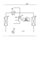
- FIG. 11 is a diagram showing a configuration example of a refrigeration cycle equipment 900 according to Embodiment 4.
- a refrigeration cycle applied equipment 900 according to the fourth embodiment includes the power converter 1 described in the first embodiment.
- the refrigerating cycle applied equipment 900 according to Embodiment 4 can be applied to products equipped with a refrigerating cycle, such as air conditioners, refrigerators, freezers, and heat pump water heaters.
- constituent elements having functions similar to those of the first embodiment are assigned the same reference numerals as those of the first embodiment.
- Refrigerating cycle applied equipment 900 includes compressor 120 incorporating motor 110 according to Embodiment 1, four-way valve 902, indoor heat exchanger 906, expansion valve 908, and outdoor heat exchanger 910 with refrigerant pipe 912. attached through
- a compression mechanism 904 that compresses the refrigerant and a motor 110 that operates the compression mechanism 904 are provided inside the compressor 120 .
- the refrigeration cycle applied equipment 900 can perform heating operation or cooling operation by switching operation of the four-way valve 902 .
- Compression mechanism 904 is driven by motor 110 whose speed is controlled.
- the refrigerant is pressurized by the compression mechanism 904 and sent out through the four-way valve 902, the indoor heat exchanger 906, the expansion valve 908, the outdoor heat exchanger 910, and the four-way valve 902. Return to compression mechanism 904 .
- the refrigerant is pressurized by the compression mechanism 904 and sent through the four-way valve 902, the outdoor heat exchanger 910, the expansion valve 908, the indoor heat exchanger 906, and the four-way valve 902. Return to compression mechanism 904 .
- the indoor heat exchanger 906 acts as a condenser to release heat, and the outdoor heat exchanger 910 acts as an evaporator to absorb heat.
- the outdoor heat exchanger 910 acts as a condenser to release heat, and the indoor heat exchanger 906 acts as an evaporator to absorb heat.
- the expansion valve 908 reduces the pressure of the refrigerant to expand it.
Landscapes
- Engineering & Computer Science (AREA)
- Power Engineering (AREA)
- Control Of Ac Motors In General (AREA)
Priority Applications (4)
| Application Number | Priority Date | Filing Date | Title |
|---|---|---|---|
| PCT/JP2021/002562 WO2022162720A1 (ja) | 2021-01-26 | 2021-01-26 | 制御装置、電力変換装置、モータ駆動装置及び冷凍サイクル適用機器 |
| JP2022577820A JP7459312B2 (ja) | 2021-01-26 | 2021-01-26 | 制御装置、電力変換装置、モータ駆動装置及び冷凍サイクル適用機器 |
| CN202180088997.9A CN116671000A (zh) | 2021-01-26 | 2021-01-26 | 控制装置、电力转换装置、马达驱动装置和制冷循环应用设备 |
| US18/254,259 US20240014759A1 (en) | 2021-01-26 | 2021-01-26 | Control device, power conversion apparatus, motor drive unit, and applied refrigeration cycle apparatus |
Applications Claiming Priority (1)
| Application Number | Priority Date | Filing Date | Title |
|---|---|---|---|
| PCT/JP2021/002562 WO2022162720A1 (ja) | 2021-01-26 | 2021-01-26 | 制御装置、電力変換装置、モータ駆動装置及び冷凍サイクル適用機器 |
Publications (1)
| Publication Number | Publication Date |
|---|---|
| WO2022162720A1 true WO2022162720A1 (ja) | 2022-08-04 |
Family
ID=82652712
Family Applications (1)
| Application Number | Title | Priority Date | Filing Date |
|---|---|---|---|
| PCT/JP2021/002562 Ceased WO2022162720A1 (ja) | 2021-01-26 | 2021-01-26 | 制御装置、電力変換装置、モータ駆動装置及び冷凍サイクル適用機器 |
Country Status (4)
| Country | Link |
|---|---|
| US (1) | US20240014759A1 (https=) |
| JP (1) | JP7459312B2 (https=) |
| CN (1) | CN116671000A (https=) |
| WO (1) | WO2022162720A1 (https=) |
Families Citing this family (2)
| Publication number | Priority date | Publication date | Assignee | Title |
|---|---|---|---|---|
| JP7345673B2 (ja) * | 2020-10-26 | 2023-09-15 | 三菱電機株式会社 | 電力変換装置、モータ駆動装置および冷凍サイクル適用機器 |
| US20250141340A1 (en) * | 2021-10-28 | 2025-05-01 | Mitsubishi Electric Corporation | Power converting apparatus, motor drive unit, and refrigeration cycle-incorporating apparatus |
Citations (3)
| Publication number | Priority date | Publication date | Assignee | Title |
|---|---|---|---|---|
| JP5156149B1 (ja) * | 2012-01-18 | 2013-03-06 | 三菱電機株式会社 | 電力変換装置 |
| WO2019187721A1 (ja) * | 2018-03-29 | 2019-10-03 | ダイキン工業株式会社 | 電力変換装置 |
| WO2020184285A1 (ja) * | 2019-03-14 | 2020-09-17 | ダイキン工業株式会社 | 直接形の電力変換装置 |
Family Cites Families (3)
| Publication number | Priority date | Publication date | Assignee | Title |
|---|---|---|---|---|
| US6307759B1 (en) * | 1997-10-31 | 2001-10-23 | Hitachi, Ltd. | Control device for electric power translating device |
| JP6614825B2 (ja) * | 2015-06-30 | 2019-12-04 | 日立ジョンソンコントロールズ空調株式会社 | 電力変換装置およびモータ駆動装置、冷凍装置 |
| WO2017212794A1 (ja) * | 2016-06-08 | 2017-12-14 | 三菱電機株式会社 | 交流電動機の速度推定装置、交流電動機の駆動装置、冷媒圧縮機および冷凍サイクル装置 |
-
2021
- 2021-01-26 US US18/254,259 patent/US20240014759A1/en not_active Abandoned
- 2021-01-26 CN CN202180088997.9A patent/CN116671000A/zh active Pending
- 2021-01-26 WO PCT/JP2021/002562 patent/WO2022162720A1/ja not_active Ceased
- 2021-01-26 JP JP2022577820A patent/JP7459312B2/ja active Active
Patent Citations (3)
| Publication number | Priority date | Publication date | Assignee | Title |
|---|---|---|---|---|
| JP5156149B1 (ja) * | 2012-01-18 | 2013-03-06 | 三菱電機株式会社 | 電力変換装置 |
| WO2019187721A1 (ja) * | 2018-03-29 | 2019-10-03 | ダイキン工業株式会社 | 電力変換装置 |
| WO2020184285A1 (ja) * | 2019-03-14 | 2020-09-17 | ダイキン工業株式会社 | 直接形の電力変換装置 |
Also Published As
| Publication number | Publication date |
|---|---|
| US20240014759A1 (en) | 2024-01-11 |
| CN116671000A (zh) | 2023-08-29 |
| JP7459312B2 (ja) | 2024-04-01 |
| JPWO2022162720A1 (https=) | 2022-08-04 |
Similar Documents
| Publication | Publication Date | Title |
|---|---|---|
| JP7466794B2 (ja) | 電力変換装置、モータ駆動装置および冷凍サイクル適用機器 | |
| WO2016002074A1 (ja) | 電力変換装置、除湿機、空調装置および冷凍装置 | |
| WO2023084600A1 (ja) | 電力変換装置、モータ駆動装置及び冷凍サイクル適用機器 | |
| JP7459312B2 (ja) | 制御装置、電力変換装置、モータ駆動装置及び冷凍サイクル適用機器 | |
| CN116857748B (zh) | 压缩机振动抑制方法、装置、空调器和存储介质 | |
| WO2023105761A1 (ja) | 電力変換装置、電動機駆動装置及び冷凍サイクル適用機器 | |
| US20240405694A1 (en) | Power converting apparatus, motor drive unit, and refrigeration cycle-incorporating device | |
| JP7012901B2 (ja) | 交流電動機の速度推定装置、交流電動機の駆動装置、冷媒圧縮機及び冷凍サイクル装置 | |
| JP7570536B2 (ja) | 電力変換装置および空気調和機 | |
| JP7542751B2 (ja) | 電力変換装置、電動機駆動装置及び冷凍サイクル適用機器 | |
| JP7195165B2 (ja) | 制御装置、モータ駆動装置、及びそれを用いた冷凍機器 | |
| WO2025069183A1 (ja) | 電力変換装置、電動機駆動装置及び冷凍サイクル適用機器 | |
| JP2020205708A (ja) | オープン巻線モータ駆動装置及び冷凍サイクル装置 | |
| WO2020095377A1 (ja) | 負荷駆動装置、冷凍サイクル装置及び空気調和機 | |
| WO2023157045A1 (ja) | 電力変換装置および空気調和機 | |
| WO2023100321A1 (ja) | 電力変換装置、モータ駆動装置及び冷凍サイクル適用機器 | |
| JP7308949B2 (ja) | 電動機駆動装置及び冷凍サイクル適用機器 | |
| WO2023095311A1 (ja) | 電力変換装置、電動機駆動装置及び冷凍サイクル適用機器 | |
| JP7345690B2 (ja) | 電力変換装置、モータ駆動装置及び冷凍サイクル適用機器 | |
| JP7710642B1 (ja) | 駆動装置、圧縮機駆動システム、および冷凍サイクル装置 | |
| JP7819347B2 (ja) | 電力変換装置、モータ駆動装置および冷凍サイクル適用機器 | |
| JP7714159B1 (ja) | 駆動装置、圧縮機駆動システム、および冷凍サイクル装置 | |
| WO2023105676A1 (ja) | 電力変換装置、モータ駆動装置及び冷凍サイクル適用機器 | |
| WO2025069182A1 (ja) | 電力変換装置、電動機駆動装置及び冷凍サイクル適用機器 | |
| WO2025220197A1 (ja) | 駆動装置、圧縮機駆動システム、および冷凍サイクル装置 |
Legal Events
| Date | Code | Title | Description |
|---|---|---|---|
| 121 | Ep: the epo has been informed by wipo that ep was designated in this application |
Ref document number: 21922745 Country of ref document: EP Kind code of ref document: A1 |
|
| ENP | Entry into the national phase |
Ref document number: 2022577820 Country of ref document: JP Kind code of ref document: A |
|
| WWE | Wipo information: entry into national phase |
Ref document number: 18254259 Country of ref document: US |
|
| WWE | Wipo information: entry into national phase |
Ref document number: 202180088997.9 Country of ref document: CN |
|
| NENP | Non-entry into the national phase |
Ref country code: DE |
|
| 122 | Ep: pct application non-entry in european phase |
Ref document number: 21922745 Country of ref document: EP Kind code of ref document: A1 |