WO2022158489A1 - 弁装置 - Google Patents
弁装置 Download PDFInfo
- Publication number
- WO2022158489A1 WO2022158489A1 PCT/JP2022/001789 JP2022001789W WO2022158489A1 WO 2022158489 A1 WO2022158489 A1 WO 2022158489A1 JP 2022001789 W JP2022001789 W JP 2022001789W WO 2022158489 A1 WO2022158489 A1 WO 2022158489A1
- Authority
- WO
- WIPO (PCT)
- Prior art keywords
- valve
- discharge port
- valve body
- chamber
- partition wall
- Prior art date
- Legal status (The legal status is an assumption and is not a legal conclusion. Google has not performed a legal analysis and makes no representation as to the accuracy of the status listed.)
- Ceased
Links
Images


Classifications
-
- B—PERFORMING OPERATIONS; TRANSPORTING
- B60—VEHICLES IN GENERAL
- B60K—ARRANGEMENT OR MOUNTING OF PROPULSION UNITS OR OF TRANSMISSIONS IN VEHICLES; ARRANGEMENT OR MOUNTING OF PLURAL DIVERSE PRIME-MOVERS IN VEHICLES; AUXILIARY DRIVES FOR VEHICLES; INSTRUMENTATION OR DASHBOARDS FOR VEHICLES; ARRANGEMENTS IN CONNECTION WITH COOLING, AIR INTAKE, GAS EXHAUST OR FUEL SUPPLY OF PROPULSION UNITS IN VEHICLES
- B60K15/00—Arrangement in connection with fuel supply of combustion engines or other fuel consuming energy converters, e.g. fuel cells; Mounting or construction of fuel tanks
- B60K15/03—Fuel tanks
- B60K15/035—Fuel tanks characterised by venting means
-
- F—MECHANICAL ENGINEERING; LIGHTING; HEATING; WEAPONS; BLASTING
- F02—COMBUSTION ENGINES; HOT-GAS OR COMBUSTION-PRODUCT ENGINE PLANTS
- F02M—SUPPLYING COMBUSTION ENGINES IN GENERAL WITH COMBUSTIBLE MIXTURES OR CONSTITUENTS THEREOF
- F02M25/00—Engine-pertinent apparatus for adding non-fuel substances or small quantities of secondary fuel to combustion-air, main fuel or fuel-air mixture
- F02M25/08—Engine-pertinent apparatus for adding non-fuel substances or small quantities of secondary fuel to combustion-air, main fuel or fuel-air mixture adding fuel vapours drawn from engine fuel reservoir
-
- F—MECHANICAL ENGINEERING; LIGHTING; HEATING; WEAPONS; BLASTING
- F02—COMBUSTION ENGINES; HOT-GAS OR COMBUSTION-PRODUCT ENGINE PLANTS
- F02M—SUPPLYING COMBUSTION ENGINES IN GENERAL WITH COMBUSTIBLE MIXTURES OR CONSTITUENTS THEREOF
- F02M37/00—Apparatus or systems for feeding liquid fuel from storage containers to carburettors or fuel-injection apparatus; Arrangements for purifying liquid fuel specially adapted for, or arranged on, internal-combustion engines
-
- F—MECHANICAL ENGINEERING; LIGHTING; HEATING; WEAPONS; BLASTING
- F16—ENGINEERING ELEMENTS AND UNITS; GENERAL MEASURES FOR PRODUCING AND MAINTAINING EFFECTIVE FUNCTIONING OF MACHINES OR INSTALLATIONS; THERMAL INSULATION IN GENERAL
- F16K—VALVES; TAPS; COCKS; ACTUATING-FLOATS; DEVICES FOR VENTING OR AERATING
- F16K24/00—Devices, e.g. valves, for venting or aerating enclosures
- F16K24/04—Devices, e.g. valves, for venting or aerating enclosures for venting only
Definitions
- the present invention relates to a valve device attached to a fuel tank of an automobile or the like and used as a fuel outflow prevention valve, a full-tank regulation valve, or the like.
- the fuel tank of a vehicle is equipped with a valve device that prevents the fuel in the fuel tank from leaking out of the fuel tank when the vehicle tilts or rolls over.
- a valve device generally has a housing with a vent chamber at the top and a valve chamber at the bottom via a partition wall having a vent hole, and a float valve arranged in the valve chamber so as to move up and down. .
- a valve case is partitioned into a gas collection chamber and a vent chamber by a partition wall, a communication port is formed in the partition wall for communicating the gas collection chamber and the ventilation chamber, and a communication port is formed on the partition wall.
- a cylindrical guide wall is erected so as to surround the peripheral edge of the port, and the guide wall is formed with a discharge port for communicating with the outside of the valve case.
- a valve device is described in which a valve body is detachable and seatable. Further, when the valve body separates from the communicating port peripheral portion and comes into contact with the valve case, the valve body seating surface is inclined with respect to the communicating port peripheral portion, and the seating surface of the valve body is inclined relative to the communicating port peripheral portion. The side farthest from the peripheral portion is set to be positioned on the outlet side.
- a float valve is arranged in the gas collecting chamber so as to be movable up and down.
- an object of the present invention is to provide a valve device that makes it difficult for the float valve to float up and makes it easy to lower the pressure in the fuel tank.
- a valve device is provided with a valve chamber downwardly communicating with the inside of a fuel tank and a vent chamber upwardly communicating with the outside of the fuel tank through a partition wall.
- a housing having a vent hole communicating between the valve chamber and the vent chamber; a float valve housed in the valve chamber so as to be movable up and down and opening and closing the vent hole;
- a fuel vapor discharge port is formed in the housing above the partition wall and communicates with the ventilation chamber, and the fuel vapor discharge port communicates with the fuel vapor discharge port.
- a fuel vapor discharge pipe connected to a canister arranged outside the tank is provided, and the valve body is configured so that the flow rate per unit time of the fluid flowing into the ventilation chamber through the ventilation hole exceeds a predetermined value. It is characterized in that it is configured to be pushed up at times to partially block the fuel vapor discharge port.
- the valve body when the pressure in the fuel tank rises and the fluid such as fuel vapor passes through the vent hole and flows into the vent chamber, and the flow rate per unit time exceeds a predetermined value, the valve body is pushed up and partially blocks the fuel vapor outlet, so that the passage area of the fuel vapor outlet is reduced. As a result, the flow resistance of the fluid flowing through the fuel vapor discharge port increases, making it difficult for the fluid to flow within the housing. It can be lowered easily.
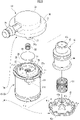
- FIG. 1 is an exploded perspective view showing one embodiment of a valve device according to the present invention
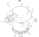
- FIG. It is a perspective view of the same valve apparatus.
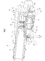
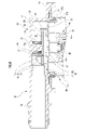
- FIG. 3 is a cross-sectional view taken along the line AA of FIG. 2;
- FIG. 2 is a perspective view of an upper cover that constitutes the same valve device, viewed from a direction different from that of FIG. 1; It is a top view of the same top cover.
- FIG. 4 is an enlarged cross-sectional perspective view of a main portion of the valve device according to the present invention, showing a state in which the valve body is lowered; 7 is an enlarged explanatory view of the state of FIG. 6;
- FIG. FIG. 4 is an enlarged explanatory view of a main part of the valve device according to the present invention in a state where the valve body is lifted;
- valve device An embodiment of a valve device according to the present invention will be described below with reference to the drawings.
- the valve device 10 of this embodiment has a valve chamber V downwardly communicating with the inside of the fuel tank and an upwardly communicating vent chamber R communicating with the outside of the fuel tank.
- a housing 15 having a partition wall 23 formed with a ventilation hole 25 communicating the valve chamber V and the ventilation chamber R; , and a valve body 80 arranged in the ventilation chamber R so as to be movable up and down.
- the housing 15 of this embodiment also has a housing body 20 , a lower cap 40 attached below the housing body 20 , and an upper cover 50 attached above the housing body 20 .
- fuel means liquid fuel (including fuel droplets)
- fuel vapor means vaporized fuel (gaseous fuel).
- the housing body 20 will be described with reference to FIGS. 1 and 4-6.
- the housing body 20 has a substantially cylindrical peripheral wall 21, above which the partition wall 23 is arranged.
- a circular ventilation hole 25 is formed in the center of the partition wall 23 to allow the valve chamber V and the ventilation chamber R to communicate with each other.
- a substantially cross-shaped rib 25a is provided inside the vent hole 25. As shown in FIG.
- a plurality of first locking claws 21a protrude at even intervals in the circumferential direction.
- a plurality of second locking claws 21b protrude above the peripheral wall 21 at equal intervals in the circumferential direction.
- a flange portion 27 protrudes from the upper outer periphery of the peripheral wall 21 .
- a ring mounting groove 27a is formed inside the flange portion 27, and an annular seal ring 27b is mounted in the ring mounting groove 27a (see FIG. 3).
- a plurality of protrusions 29 are provided on the upper surface side of the partition wall 23 and outside the ventilation holes 25 at equal intervals in the circumferential direction. These protrusions 29 support the valve body 80 in a floating state from the upper surface of the partition wall 23 (see FIG. 3) so that the vent hole 25 is not completely blocked even when the valve body 80 is lowered. do.
- a substantially cylindrical guide wall 31 is provided with a separation portion 31a at a part in the circumferential direction. is established.
- the guide wall 31 has the valve body 80 disposed therein, guides the upward/downward movement of the valve body 80, and regulates the position in the radial direction.
- the lower cap 40 has a bottom wall 41 and a peripheral wall 43 erected from the peripheral edge of the bottom wall 41 .
- the bottom wall 41 is formed with a plurality of through holes 41a.
- a plurality of locking holes 43a are formed in the peripheral wall 43 at equal intervals in the circumferential direction. Then, the peripheral wall 43 of the lower cap 40 is put on the outer periphery of the lower end of the peripheral wall 21 of the housing body 20, and the first locking claws 21a corresponding to the locking holes 43a are engaged with each other.
- a lower cap 40 is attached below (see FIG. 2).
- a valve chamber V communicating with the inside of the fuel tank (not shown) is formed below the housing through the partition wall 23 (see FIG. 3).
- a float valve 45 for opening and closing the vent hole 25 is arranged between the lower cap 40 and a float valve biasing spring S1 (hereinafter simply referred to as "biasing spring S1") made of a coil spring. ) is interposed, and is housed and arranged so as to be able to move up and down.
- biasing spring S1 float valve biasing spring S1
- the float valve 45 rises by its own buoyancy and the biasing force of the biasing spring S1 when immersed in fuel, and descends by its own weight when not immersed in fuel.
- the float valve 45 includes a float body 46 having a circular outer periphery that generates buoyancy when immersed in fuel, and a seal member 47 that is mounted above the float body 46 and moves up and down relative to the float body 46. and A seal valve element 47a made of an elastic material such as rubber or elastic elastomer is mounted above the seal member 47. As shown in FIG. The seal valve body 47a contacts and separates from the periphery of the lower opening of the ventilation hole 25 to open and close the ventilation hole 25. As shown in FIG. Further, an intermediate valve body 48 is tiltably supported between the float body 46 and the seal member 47 (see FIG. 3). The float valve 45 contacts and separates from the periphery of the lower opening of the ventilation hole 25 by its up-and-down movement to open and close the ventilation hole 25, thereby functioning as a fuel outflow prevention valve and a full tank regulation valve.
- the upper cover 50 constituting the housing 15 includes a peripheral wall 51 having a substantially circular outer periphery and a ceiling wall 53 disposed above the peripheral wall 51 and facing the partition wall 23 . , and a flange portion 55 extending outward from the lower side of the peripheral wall 51, forming a substantially hat shape.
- a plurality of locking pieces 57 extend from the lower end of the peripheral wall 51 at equal intervals in the circumferential direction.
- Each locking piece 57 is formed with a locking hole 57a with which the second locking claw 21b provided on the housing body 20 is locked.
- the housing 15 is formed with a fuel vapor discharge port 70 (hereinafter simply referred to as “discharge port 70") communicating with the ventilation chamber R above the partition wall 23.
- a fuel vapor discharge pipe 75 (hereinafter also simply referred to as “discharge pipe 75”) is provided which communicates with the discharge port 70 and is connected to a not-shown canister disposed outside the fuel tank.
- the housing 15 is provided with a projecting portion 60 projecting in a tubular shape toward the inside of the ventilation chamber R and communicating with the discharge pipe 75 , and the projecting portion 60 has a discharge port 70 formed on the outer periphery thereof. .
- the upper cover 50 that constitutes the housing 15 is provided with a discharge port 70 and a discharge pipe 75 .
- the protruding portion 60 is a predetermined portion in the circumferential direction of the peripheral wall 51 of the upper cover 50 and protrudes in a tubular shape from the inner peripheral surface toward the radial center of the upper cover 50 (the radial center of the ceiling wall 53). It is composed of a first projecting portion 61 and a second projecting portion 63 which is connected to the end of the projecting direction of the first projecting portion 61 and has a frame-like shape with an opening mainly downward (in the direction facing the partition wall 23). ing.
- the first projecting portion 61 has a ceiling portion 61a connected to the ceiling wall 53 of the upper cover 50 and a bottom portion 61b opposite to the ceiling portion 61a, which are parallel to each other.
- the portions 61c, 61c are in the shape of a deformed tube with circular arcs.
- a first discharge port 71 communicating with a discharge pipe 75 is formed at the tip of the first projecting portion 61 in the projecting direction.
- the second projecting portion 63 includes a pair of projecting walls 64, 64 projecting from both ends of the projecting direction of the first projecting portion 61, and a pair of projecting walls 64, 64 extending from the projecting ends of the projecting walls 64, 64. a pair of side walls 65, 65 extending perpendicularly and parallel to each other;
- a connection wall 66 is arranged at a predetermined distance from the first discharge port 71 of 61, and has a substantially square frame shape with an open bottom. The upper ends of the walls 64 , 65 , 66 are connected to the ceiling wall 53 of the upper cover 50 . Moreover, as shown in FIG.
- the protrusion amount of the side wall 65 and the connection wall 66 from the inner surface of the ceiling wall 53 is the same. Furthermore, as shown in FIG. 4, the side wall 65 and the connecting wall 66 protrude so as to be one step lower than the overhang wall 64 .
- the spaces surrounded by the walls 64 , 65 , 66 communicate with the first discharge port 71 of the first projecting portion 61 .
- a lower opening of the second protrusion 63 forms a second discharge port 72 and communicates with the space surrounded by the plurality of walls 64 , 65 , 66 .
- Each side wall 65 is also formed with a notched third discharge port 73 that communicates with the space surrounded by the walls 64 , 65 , 66 .
- the third discharge port 73 has an inner surface 73a on the side of the connecting wall 66 that forms a vertical surface, and an inner surface 73b on the side of the overhang wall 64 that gradually widens with respect to the inner surface 73a from the ceiling wall 53 side toward the lower end. It has a tapered surface that is inclined so that
- each side wall 65 (the end facing the partition wall 23) on the inner surface 73a side and the end face of the lower end of the connecting wall 66 (the end facing the partition wall 23) are stepless.
- a continuous flat valve contact surface 67 is formed (see FIG. 4), and a valve disc 80 contacts this valve contact surface 67 when the valve is raised (see FIG. 4). 8).
- This valve contact surface 67 forms the "end surface facing the partition wall" of the projecting portion in the present invention.
- An end surface 67a (see FIG. 4) of each side wall 65 on the side of the inner surface 73b, which is the lower end portion, does not come into contact with the valve body 80 even if it rises.
- a first discharge port 71 formed in the first projecting portion 61, a second discharge port 72 formed in the second projecting portion 63, and a second discharge port 72 formed in the side wall 65 of the second projecting portion 63 are provided.
- 3 discharge port 73 constitutes the "fuel vapor discharge port” in the present invention.
- the "fuel vapor discharge port” in the present invention means an opening communicating with the internal space of the fuel vapor discharge pipe and communicating with the inside of the ventilation chamber.
- the second discharge port 72 constituting the discharge port 70 constitutes "a portion opened toward the partition wall” in the present invention.
- the projecting portion 60 having the structure described above is formed as shown in FIG. enters the inside of the guide wall 31, the first protrusion 61 is arranged outside the guide wall 31 at a position aligned with the separation portion 31a, and the first protrusion formed in the first protrusion 61 An outlet 71 is arranged so as to face the separating portion 31a.
- the projecting portion 60 including the first projecting portion 61 and the second projecting portion 63 is provided.
- the fuel vapor outlet 70 consisting of 72 and the third outlet 73 is provided, the fuel vapor outlet is not limited to this aspect.
- a fuel vapor discharge port may be provided at a predetermined location on the peripheral wall 51 of the upper cover 50, or (2) a fuel vapor discharge port may be provided at the tip of a tubular projecting portion projecting from the peripheral wall 51 in the projecting direction (this (3) A fuel vapor discharge port is provided at a predetermined location on the ceiling wall 53 or at the tip of the tubular projection extending from the ceiling wall 53 in the projecting direction.
- the overall shape of the protrusion may be, for example, a shape that extends in a simple straight tube shape, or the second protrusion that constitutes the protrusion may be a circular, oval, or oval frame shape, An opening may be provided only in the side wall without providing a lower opening in the second protrusion, and the shape and structure of the protrusion are not particularly limited.
- the opening angle of the first discharge port 71 constituting the fuel vapor discharge port 70 in this embodiment (meaning the angle of the surface surrounded by the opening; the same applies to the following description) is vertical (the vertical direction of the valve body ), and the opening angle of the second discharge port 72 is horizontal (perpendicular to the vertical direction of the valve body), but the opening angle of the fuel vapor discharge port is You may incline at a predetermined angle with respect to the raising/lowering direction of a valve body.
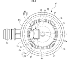
- the discharge pipe 75 extends radially outward from a position aligned with the first projecting portion 61 on the outer surface side of the peripheral wall 51 of the upper cover 50 . As shown in FIG. 5 , when the housing 15 is viewed from the axial direction, the discharge pipe 75 extends on the same straight line as the first projecting portion 61 .
- a tube (not shown) connected to a canister arranged outside the fuel tank is connected to the discharge pipe 75 .
- a substantially cylindrical projection 77 protrudes toward the partition wall 23 from the radial center of the ceiling wall 53 of the upper cover 50 and from the inner surface side thereof.
- the protrusion 77 protrudes perpendicularly to the planar direction of the ceiling wall 53 .
- a lower end surface 77a which is the leading end of the protrusion 77 in the projecting direction, has a flat shape.
- the protrusion amount of the projection 77 from the inner surface of the ceiling wall 53 is the same as the protrusion amount of the side wall 65 and the connecting wall 66 .
- the valve element 80 arranged in the ventilation chamber R so as to be able to move up and down is in the form of a disc with a constant thickness and made of metal such as stainless steel in the case of this embodiment. .
- the outer diameter of the valve body 80 is set to be larger than the outer dimension of the second projecting portion 63 forming the projecting portion 60.
- the valve body 80 is disposed inside the guide wall 31 in the ventilation chamber R and above the ventilation hole 25 formed in the partition wall 23 so as to be able to move up and down.
- a plurality of projections 29 provided on the upper surface of the wall 23 support the partition wall 23 in a floating state.
- the valve element 80 is arranged inside the guide wall 31 so that its movement in the radial direction is restricted so that the upper opening of the vent hole 25 formed in the partition wall 23 is always covered.
- a valve body biasing spring S2 (hereinafter also simply referred to as “biasing spring S2") made of a coil spring is interposed around the outer periphery of the projection 77, and this biasing spring S2 causes the valve body to 80 is biased toward the partition wall 23 side. That is, the valve body 80 is normally biased toward the partition wall 23 by the biasing means (here, the valve body biasing spring S2). However, the valve body 80 may be lowered only by its own weight without providing the valve body biasing spring S2. In this case, the weight of the valve body 80 serves as the urging means.
- the valve body 80 is pushed up to partially block the fuel vapor discharge port 70 when the flow rate per unit time of the fluid flowing into the ventilation chamber R through the ventilation hole 25 exceeds a predetermined value.
- valve body 80 when fuel is supplied to a fuel tank (not shown) and the pressure in the fuel tank rises, as shown in FIGS. After flowing into the chamber V, it passes through the vent hole 25 and comes into contact with the lower surface of the valve body 80 .
- the valve body 80 When the flow rate of the fluid per unit time exceeds a predetermined value set by the biasing force of the biasing spring S2 and the self-weight of the valve body 80, the valve body 80 is pushed up, and the discharge port 70 is partially closed. is blocked (see FIG. 8).
- the valve body 80 is preferably pushed up when, for example, the flow rate of the fluid per unit time exceeds 200 L/min.
- the valve body 80 abuts on the valve body contact surface 67 provided on the projecting portion 60 and the lower end surface 77a of the projection 77, respectively, and the valve body 80 extends beyond that.
- the first discharge port 71 is partially blocked by the thickness of the valve body 80 (the lower opening portion of the first discharge port 71 is blocked).
- the second discharge port 72 is partially blocked by the valve body 80 which is larger than the second projecting portion 63. (The second discharge port 72 is closed except for the portion near the first projecting portion 61.)
- (3) As shown in FIG. is partially blocked by the valve body 80 . In this way, the discharge port 70 is partially blocked by the valve body 80 .
- the shape and structure of the housing body, lower cap, and upper cover that constitute the housing described above are not particularly limited. Further, the housing does not have to be composed of three parts, ie, the housing main body, the lower cap, and the upper cover. Furthermore, the float valve 45 in this embodiment has a multi-part structure consisting of a float body 46, a seal member 47, and the like. etc., and the shape and structure are not particularly limited as long as the air vent 25 can be opened and closed.
- the valve body 80 partially closes all of the discharge ports 71, 72, and 73 that constitute the discharge port 70, but the valve body partially closes the fuel vapor discharge port.
- the covering configuration is not limited to this aspect.
- the valve body is formed in the shape of a square plate that is larger than the second projecting portion, and when the valve body rises, it blocks the entire range of the second discharge port 72 and partially blocks the first discharge port 71.
- the plate thickness of the valve body may be increased or decreased to adjust the amount of partial blockage of the first discharge port, or the position of the valve body may be shifted in the radial direction with respect to the second discharge port. , the amount of partial blockage of the second discharge port and the third discharge port may be adjusted.
- valve element 80 in this embodiment has a disk shape, it may have a polygonal shape, an elliptical shape, an oval shape, or the like, or may have a through-hole, or may have a fuel vapor shape. Any shape may be used as long as it can partially block the discharge port 70 .
- This valve device 10 is mainly installed in the fuel tank of a so-called hybrid car (any type of hybrid car, such as a series system, a parallel system, or a split system) having a gasoline engine and an electric motor.
- the valve device 10 of the present invention may of course be attached to the fuel tank of a vehicle that employs only a normal gasoline engine instead of a hybrid vehicle.
- the valve body 80 is urged by its own weight and the urging spring S2 to descend, and is supported by the plurality of projections 29 in a floating state from the upper surface of the partition wall 23. , and the upper opening of the ventilation hole 25 is also open. Therefore, the valve chamber V and the vent chamber R communicate with each other through the vent hole 25 .
- the first discharge port 71 is partially blocked by the thickness of the valve body 80 (see FIG. 8), and the second discharge port 72 and the third discharge port 73 are partially blocked by the valve body 80. is blocked (see FIG. 5), and the discharge port 70 is partially blocked by the valve body 80 .
- the flow path area of the discharge port 70 is narrowed, so that the flow resistance of the fluid F flowing through the discharge port 70 increases, making it difficult for the fluid F to flow within the housing 15 .
- the float valve 45 can be made less likely to float, making it easier to lower the pressure in the fuel tank.
- the housing 15 is provided with a projecting portion 60 projecting inwardly of the ventilation chamber R in a tubular shape and communicating with the discharge pipe 75.
- a discharge port 70 is formed on the outer periphery of the projecting portion 60 .
- the degree of freedom in forming the discharge port 70 can be increased, so that the discharge port 70 can be formed into a shape that is easy to partially block with the valve body 80 . If the protruding portion 60 is not provided, for example, it is necessary to provide the discharge port 70 in the peripheral wall 51 of the upper cover 50 or the like, which tends to make it difficult to partially block the discharge port 70 with the valve body 80 .
- the outlet 70 has a portion that opens toward the partition wall 23 (here, as shown in FIG. 7, the second outlet 72 opens toward the partition wall 23). is doing).
- the protruding portion 60 has an end surface (here, the valve body contact surface 67) facing the partition wall 23, and the valve body 80 is plate-shaped and protrudes when ascending. It is configured to contact the end surface of the portion 60 (see FIG. 8).
- valve body 80 when the valve body 80 is raised, the valve body 80 can be brought into contact with the projecting portion 60 in a stable posture, so that the flow passage area of the discharge port 70 can be narrowed more stably. can.
- the housing 15 has a ceiling wall 53 that faces the partition wall 23.
- a projection 77 protrudes from the ceiling wall 53 toward the partition wall 23, and the valve body 80 is When it rises and comes into contact with the end surface (valve contact surface 67) of the projecting portion 60, it also comes into contact with the lower end surface 77a of the protrusion 77 (see FIG. 8).
- valve body 80 when the valve body 80 is raised, the valve body 80 can be brought into contact with the protrusion 60 in a more stable posture by the two points of the end surface of the protrusion 60 and the lower end surface 77a of the protrusion 77. can.
- Fuel tank valve device (valve device) 15 Housing 20 Housing body 23 Partition wall 25 Vent 40 Lower cap 45 Float valve 50 Upper cover 51 Peripheral wall 53 Ceiling wall 60 Projection 67 Valve body contact surface (end surface) 70 fuel vapor outlet (outlet) 75 fuel vapor exhaust pipe (exhaust pipe) 77 Protrusion 80 Valve disc V Valve chamber R Vent chamber
Landscapes
- Engineering & Computer Science (AREA)
- Mechanical Engineering (AREA)
- Chemical & Material Sciences (AREA)
- Combustion & Propulsion (AREA)
- General Engineering & Computer Science (AREA)
- Life Sciences & Earth Sciences (AREA)
- Sustainable Development (AREA)
- Sustainable Energy (AREA)
- Transportation (AREA)
- Cooling, Air Intake And Gas Exhaust, And Fuel Tank Arrangements In Propulsion Units (AREA)
- Float Valves (AREA)
- Self-Closing Valves And Venting Or Aerating Valves (AREA)
Priority Applications (1)
| Application Number | Priority Date | Filing Date | Title |
|---|---|---|---|
| JP2022576719A JP7488918B2 (ja) | 2021-01-25 | 2022-01-19 | 弁装置 |
Applications Claiming Priority (2)
| Application Number | Priority Date | Filing Date | Title |
|---|---|---|---|
| JP2021-009749 | 2021-01-25 | ||
| JP2021009749 | 2021-01-25 |
Publications (1)
| Publication Number | Publication Date |
|---|---|
| WO2022158489A1 true WO2022158489A1 (ja) | 2022-07-28 |
Family
ID=82549422
Family Applications (1)
| Application Number | Title | Priority Date | Filing Date |
|---|---|---|---|
| PCT/JP2022/001789 Ceased WO2022158489A1 (ja) | 2021-01-25 | 2022-01-19 | 弁装置 |
Country Status (2)
| Country | Link |
|---|---|
| JP (1) | JP7488918B2 (enExample) |
| WO (1) | WO2022158489A1 (enExample) |
Cited By (1)
| Publication number | Priority date | Publication date | Assignee | Title |
|---|---|---|---|---|
| WO2025003998A1 (en) * | 2023-06-28 | 2025-01-02 | Eaton Intelligent Power Limited | Fuel tank valve systems and methods of assembly |
Citations (5)
| Publication number | Priority date | Publication date | Assignee | Title |
|---|---|---|---|---|
| WO2015122408A1 (ja) * | 2014-02-12 | 2015-08-20 | 株式会社ニフコ | 弁装置 |
| WO2016031726A1 (ja) * | 2014-08-25 | 2016-03-03 | 株式会社パイオラックス | 弁ケースの取付構造 |
| JP2018013087A (ja) * | 2016-07-21 | 2018-01-25 | 京三電機株式会社 | 燃料タンク用通気制御弁 |
| WO2019198596A1 (ja) * | 2018-04-11 | 2019-10-17 | 株式会社パイオラックス | 弁装置 |
| WO2020084156A1 (en) * | 2018-10-26 | 2020-04-30 | Plastic Omnium Advanced Innovation And Research | Valve for controlling a pressure differential |
-
2022
- 2022-01-19 JP JP2022576719A patent/JP7488918B2/ja active Active
- 2022-01-19 WO PCT/JP2022/001789 patent/WO2022158489A1/ja not_active Ceased
Patent Citations (5)
| Publication number | Priority date | Publication date | Assignee | Title |
|---|---|---|---|---|
| WO2015122408A1 (ja) * | 2014-02-12 | 2015-08-20 | 株式会社ニフコ | 弁装置 |
| WO2016031726A1 (ja) * | 2014-08-25 | 2016-03-03 | 株式会社パイオラックス | 弁ケースの取付構造 |
| JP2018013087A (ja) * | 2016-07-21 | 2018-01-25 | 京三電機株式会社 | 燃料タンク用通気制御弁 |
| WO2019198596A1 (ja) * | 2018-04-11 | 2019-10-17 | 株式会社パイオラックス | 弁装置 |
| WO2020084156A1 (en) * | 2018-10-26 | 2020-04-30 | Plastic Omnium Advanced Innovation And Research | Valve for controlling a pressure differential |
Cited By (1)
| Publication number | Priority date | Publication date | Assignee | Title |
|---|---|---|---|---|
| WO2025003998A1 (en) * | 2023-06-28 | 2025-01-02 | Eaton Intelligent Power Limited | Fuel tank valve systems and methods of assembly |
Also Published As
| Publication number | Publication date |
|---|---|
| JPWO2022158489A1 (enExample) | 2022-07-28 |
| JP7488918B2 (ja) | 2024-05-22 |
Similar Documents
| Publication | Publication Date | Title |
|---|---|---|
| JP3931291B2 (ja) | 燃料タンクの燃料流出規制装置 | |
| US20090211649A1 (en) | Fuel cutoff valve | |
| JP5874601B2 (ja) | 燃料遮断弁 | |
| US6591855B2 (en) | Fuel cutoff valve | |
| JP4135664B2 (ja) | 燃料遮断弁 | |
| JP3909837B2 (ja) | 燃料タンクの燃料流出規制装置 | |
| JP6295905B2 (ja) | 燃料遮断弁 | |
| JP2006097674A (ja) | 燃料遮断弁 | |
| JP2010143498A (ja) | 燃料遮断弁 | |
| WO2022158489A1 (ja) | 弁装置 | |
| JP5660070B2 (ja) | 燃料遮断弁 | |
| JP2012071639A (ja) | 燃料遮断弁 | |
| US6779545B2 (en) | Pressure control valve for fuel tank | |
| US20110278482A1 (en) | Fuel shut-off valves | |
| US20110017320A1 (en) | Fuel Cutoff valve | |
| US7963296B2 (en) | Fuel cutoff valve | |
| JP7442698B2 (ja) | 弁装置 | |
| JP7462834B2 (ja) | ピラー付き弁装置 | |
| JP7394238B2 (ja) | 燃料タンク用弁装置 | |
| JP7441339B2 (ja) | 満タン規制バルブ | |
| JP6070453B2 (ja) | 燃料遮断装置 | |
| JP2012180037A (ja) | 燃料遮断弁 | |
| JP7553365B2 (ja) | 弁装置 | |
| JP7422246B2 (ja) | 満タン規制バルブ | |
| JP2021032146A (ja) | 燃料遮断弁 |
Legal Events
| Date | Code | Title | Description |
|---|---|---|---|
| 121 | Ep: the epo has been informed by wipo that ep was designated in this application |
Ref document number: 22742611 Country of ref document: EP Kind code of ref document: A1 |
|
| ENP | Entry into the national phase |
Ref document number: 2022576719 Country of ref document: JP Kind code of ref document: A |
|
| NENP | Non-entry into the national phase |
Ref country code: DE |
|
| 122 | Ep: pct application non-entry in european phase |
Ref document number: 22742611 Country of ref document: EP Kind code of ref document: A1 |