WO2022158298A1 - アダプタハーネス - Google Patents
アダプタハーネス Download PDFInfo
- Publication number
- WO2022158298A1 WO2022158298A1 PCT/JP2022/000201 JP2022000201W WO2022158298A1 WO 2022158298 A1 WO2022158298 A1 WO 2022158298A1 JP 2022000201 W JP2022000201 W JP 2022000201W WO 2022158298 A1 WO2022158298 A1 WO 2022158298A1
- Authority
- WO
- WIPO (PCT)
- Prior art keywords
- holder
- connector
- connectors
- attached
- connector housing
- Prior art date
- Legal status (The legal status is an assumption and is not a legal conclusion. Google has not performed a legal analysis and makes no representation as to the accuracy of the status listed.)
- Ceased
Links
Images


Classifications
-
- H—ELECTRICITY
- H01—ELECTRIC ELEMENTS
- H01R—ELECTRICALLY-CONDUCTIVE CONNECTIONS; STRUCTURAL ASSOCIATIONS OF A PLURALITY OF MUTUALLY-INSULATED ELECTRICAL CONNECTING ELEMENTS; COUPLING DEVICES; CURRENT COLLECTORS
- H01R13/00—Details of coupling devices of the kinds covered by groups H01R12/70 or H01R24/00 - H01R33/00
- H01R13/46—Bases; Cases
-
- H—ELECTRICITY
- H01—ELECTRIC ELEMENTS
- H01R—ELECTRICALLY-CONDUCTIVE CONNECTIONS; STRUCTURAL ASSOCIATIONS OF A PLURALITY OF MUTUALLY-INSULATED ELECTRICAL CONNECTING ELEMENTS; COUPLING DEVICES; CURRENT COLLECTORS
- H01R13/00—Details of coupling devices of the kinds covered by groups H01R12/70 or H01R24/00 - H01R33/00
- H01R13/46—Bases; Cases
- H01R13/502—Bases; Cases composed of different pieces
- H01R13/506—Bases; Cases composed of different pieces assembled by snap action of the parts
-
- H—ELECTRICITY
- H01—ELECTRIC ELEMENTS
- H01R—ELECTRICALLY-CONDUCTIVE CONNECTIONS; STRUCTURAL ASSOCIATIONS OF A PLURALITY OF MUTUALLY-INSULATED ELECTRICAL CONNECTING ELEMENTS; COUPLING DEVICES; CURRENT COLLECTORS
- H01R13/00—Details of coupling devices of the kinds covered by groups H01R12/70 or H01R24/00 - H01R33/00
- H01R13/46—Bases; Cases
- H01R13/516—Means for holding or embracing insulating body, e.g. casing, hoods
- H01R13/518—Means for holding or embracing insulating body, e.g. casing, hoods for holding or embracing several coupling parts, e.g. frames
-
- H—ELECTRICITY
- H01—ELECTRIC ELEMENTS
- H01R—ELECTRICALLY-CONDUCTIVE CONNECTIONS; STRUCTURAL ASSOCIATIONS OF A PLURALITY OF MUTUALLY-INSULATED ELECTRICAL CONNECTING ELEMENTS; COUPLING DEVICES; CURRENT COLLECTORS
- H01R31/00—Coupling parts supported only by co-operation with counterpart
- H01R31/06—Intermediate parts for linking two coupling parts, e.g. adapter
-
- H—ELECTRICITY
- H02—GENERATION; CONVERSION OR DISTRIBUTION OF ELECTRIC POWER
- H02G—INSTALLATION OF ELECTRIC CABLES OR LINES, OR OF COMBINED OPTICAL AND ELECTRIC CABLES OR LINES
- H02G3/00—Installations of electric cables or lines or protective tubing therefor in or on buildings, equivalent structures or vehicles
- H02G3/02—Details
- H02G3/08—Distribution boxes; Connection or junction boxes
- H02G3/16—Distribution boxes; Connection or junction boxes structurally associated with support for line-connecting terminals within the box
Definitions
- the present disclosure relates to adapter harnesses.
- Patent Document 1 discloses an interconnection box, which is sometimes called a junction box.
- the interconnection box has multiple connectors attached to the case.
- a mating connector is connected to each of the plurality of connectors.
- mating connectors are electrically interconnected by electrically connecting a plurality of connectors to each other.
- An object of the present disclosure is to provide an adapter harness as an alternative to an interconnection box, which can reduce the installation space of installed parts.
- An adapter harness of the present disclosure includes a holder and wiring attached to the holder, wherein the wiring includes a plurality of connectors to which mating connectors different from each other are connected, and a wiring between the plurality of connectors. and a plurality of electric wires that electrically connect each other, the wiring includes a branch portion for branching the electric wire, a mounting portion mounted with an electronic component for distributing power from a power supply to a plurality of devices, and at least one of
- the adapter harness of the present disclosure it is possible to provide the adapter harness as a substitute for the interconnection box, which can reduce the installation space for the installation parts.
- FIG. 1 is a perspective view showing the adapter harness of the embodiment.
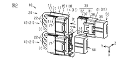
- FIG. FIG. 2 is a perspective view partially showing the adapter harness of the same form.
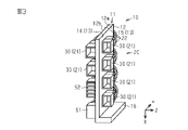
- FIG. 3 is a schematic diagram schematically showing an adapter harness in which a branch portion and a mounting portion are attached to a holder in the same embodiment.
- FIG. 4 is a perspective view showing a modified adapter harness.
- the adapter harness of the present disclosure includes: [1] An adapter harness comprising a holder and wiring attached to the holder, wherein the wiring includes a plurality of connectors to which mutually different mating connectors are connected, and an electrical connection between the plurality of connectors. and a plurality of electric wires to be connected, wherein the wiring includes at least one of a branching portion for branching the electric wires and a mounting portion to which an electronic component for distributing power from a power source to a plurality of devices is mounted. have more.
- the adapter harness has at least one of the branch portion and the mounting portion in addition to the connector and the electric wire. Therefore, since at least one of the branching portion and the mounting portion can be integrated into the adapter harness, it is possible to reduce the arrangement space of the installation parts such as the branching portion and the mounting portion.
- the plurality of connectors have connector terminals electrically connected to ends of the electric wires, and connector housings that accommodate the connector terminals, and the connector housings are separate from the holders. and attached to the holder.
- the connector housing is separate from the holder, it is possible to change the position of the connector housing in addition to the replacement of the electric wire in accordance with the specification change of the mating connector. Therefore, compared to the case where the connector housing is integrated with the holder, it is possible to electrically connect a plurality of connectors with a highly versatile configuration.
- the holder has a plurality of first connecting portions having a shape common to each other, the connector housing has a second connecting portion having a shape common to the plurality of connectors, and the second connecting portion has a shape common to the plurality of connectors.
- a portion is attached to the holder by connecting with the first connecting portion.
- the plurality of first connecting portions have a shape common to each other.
- the second connecting portion has a shape common to a plurality of connectors. Therefore, the position of the connector housing can be selected among the formation positions of the plurality of first connecting portions in the holder. Therefore, electrical connections between a plurality of connectors can be made with a more versatile configuration.
- the holder has a flat portion, and the plurality of first connecting portions are arranged on the flat portion. According to this configuration, the connector housings of the plurality of connectors are attached to the planar portion by connecting the second connecting portion to the first connecting portion. Therefore, compared to the case where the mounting location of the connector housing in the holder has a shape surrounding the connector housing, the mounting location of the connector housing is less likely to be restricted due to the shape of the holder. Therefore, it is possible to improve the degree of freedom in the mounting position of the connector housing with respect to the holder, and it is possible to perform electrical connection between a plurality of connectors with a more versatile configuration.
- the holder has a flat plate portion whose front surface and back surface are the flat surface portions, and the connector housing is attached separately to the front surface and the back surface for each connector. According to this configuration, the connector housing is attached to the front and back of the flat plate portion, so that the space for arranging the adapter harness can be reduced.
- the drawing shows the X-axis, Y-axis, and Z-axis that are orthogonal to each other.
- the direction parallel to the X-axis is also called the first direction X
- the direction parallel to the Y-axis is also called the second direction Y
- the direction parallel to the Z-axis is also called the third direction Z.
- the adapter harness 10 has a holder 11 .
- the adapter harness 10 is for connecting, for example, between an ECU and an electric device, between an electric device and a branch portion, between an electric device and a power supply portion, and between electric devices not directly related to the ECU.
- Electrical equipment is mounted in, for example, an engine room, an instrument panel, a floor of a vehicle, and the like.
- the holder 11 has a flat plate portion 12 .
- the flat plate portion 12 has a flat plate shape extending perpendicular to the Z-axis.
- the flat plate portion 12 has a rectangular shape when viewed from the third direction Z.
- a front surface 12a and a back surface 12b of the flat plate portion 12 are planar.
- the flat plate portion 12 has a flat portion 13 on each of the front surface 12a and the back surface 12b. In other words, it can be said that the holder 11 has the plane portion 13 .
- the plane portion 13 positioned on the surface 12 a of the flat plate portion 12 is called a first plane portion 14 .
- the plane portion 13 positioned on the rear surface 12 b of the flat plate portion 12 is called a second plane portion 15 .
- the term "rectangle" includes a shape with chamfered edges and a shape with rounded edges.
- the holder 11 has a base portion 16.
- the base portion 16 is connected to the end portion of the flat plate portion 12 in the first direction X. As shown in FIG.
- the base portion 16 is in the shape of a rectangular flat plate.
- the length of the base portion 16 extends in the second direction Y.
- a short side of the base portion 16 extends in the third direction Z. As shown in FIG.
- the holder 11 is attached to the vehicle, for example, in such a manner that the base portion 16 is seated on the vehicle. Further, the holder 11 may have a mounting seat (not shown) around the flat portion 13 of the flat portion 12 .
- the mounting seat has, for example, a flat plate shape and a through hole penetrating in the thickness direction. For example, the holder 11 is attached to the vehicle by threading a bolt or the like into a nut through a through hole of the attachment seat.
- the holder 11 has a plurality of first connecting portions 17. As shown in FIG. The plurality of first connecting portions 17 are arranged on the plane portion 13 of the holder 11 . The plurality of first connecting portions 17 are arranged on both the first plane portion 14 and the second plane portion 15 . Four first connecting portions 17 of the present embodiment are arranged on the first plane portion 14 and two are arranged on the second plane portion 15 . The plurality of first connecting portions 17 are arranged in the first direction X in each of the first plane portion 14 and the second plane portion 15 .
- first connecting portions 17 arranged on the first plane portion 14 are illustrated in detail. Detailed illustration of the remaining two first connecting portions 17 arranged on the first plane portion 14 and the remaining two first connecting portions 17 arranged on the second plane portion 15 is omitted.
- the plurality of first connecting portions 17 have a shape common to each other and have compatibility. Therefore, the following description of the shape of the first connecting portion 17 is common to all the first connecting portions 17 .
- the first connecting portion 17 has a first protruding portion 18 and a first extending portion 19 .
- the first protruding portion 18 protrudes from the flat portion 13 .
- the first projecting portion 18 is positioned so as to surround the first extending portion 19 from three directions of the first direction X, the direction opposite to the first direction X, and the second direction Y.
- the first extension portion 19 has a flat plate shape. An end portion of the first extension portion 19 in the second direction Y is connected to the first projecting portion 18 . Of the end portions of the first extension portion 19 , the portion other than the portion connected to the first projecting portion 18 is separated from the first projecting portion 18 .
- the end portion of the first extension portion 19 connected to the first projecting portion 18 is the base end of the first extension portion 19, and the end portion opposite to the base end of the first extension portion 19 is the first extension portion. It is the tip of the part 19 .
- the distal end of the first elongated portion 19 can be displaced in the thickness direction of the first elongated portion 19 with the base end as a fulcrum.
- the first extended portion 19 is located away from the flat portion 13 .
- the adapter harness 10 has wiring 20 attached to the holder 11 .
- the wiring 20 has multiple connectors 21 and multiple electric wires 22 .
- the wiring 20 of this embodiment has six connectors 21 .
- Each of the plurality of electric wires 22 electrically connects the plurality of connectors 21 to each other.
- the plurality of electric wires 22 are, for example, covered electric wires having a core wire 23 made of a conductor and an insulating coating 24 covering the outer periphery of the core wire 23 .
- the multiple connectors 21 have connector terminals 25 and connector housings 30 that accommodate the connector terminals 25 .
- the connector terminal 25 is electrically connected to the axial end of each electric wire 22 .
- the connector housing 30 is separate from the holder 11 .
- the connectors 21 are attached to the holder 11 by attaching the connector housing 30 to the holder 11 .
- the connector housing 30 has, for example, a tubular inserting portion 31 and a rectangular pole-like holding portion 32 .
- the axial direction of the insertion portion 31 coincides with the second direction Y when the connector housing 30 is attached to the holder 11 .
- the axial directions of the insertion portion 31 and the holding portion 32 are aligned with each other.
- the insertion portion 31 is connected to the holding portion 32 at one end in the axial direction and has an opening 31h at the other end in the axial direction.
- the opening 31 h opens to the outside of the insertion section 31 and communicates with the internal space of the insertion section 31 .
- the holding part 32 holds one or more electric wires 22 inside.
- the holding part 32 of this embodiment holds the three electric wires 22 inside.
- a plurality of electric wires 22 pass through the inside of the holding portion 32 .
- a portion of the electric wire 22 that is not held inside the holding portion 32 is exposed to the outside of the holding portion 32 from the end portion of the holding portion 32 in the second direction Y.
- the connector terminal 25 of each of the plurality of electric wires 22 is exposed inside the insertion portion 31 from inside the holding portion 32 .
- first connector 41 and second connector 42 A plurality of connectors 21 are attached to each of the first plane portion 14 and the second plane portion 15 of the holder 11 .
- Four connectors 21 of this embodiment are attached to the first flat portion 14 and two are attached to the second flat portion 15 .
- the connector 21 attached to the first plane portion 14 is called a first connector 41
- the connector 21 attached to the second plane portion 15 is called a second connector 42 .
- the first connector 41 has one or more connector terminals 25 .
- the first connector 41 of this embodiment has three connector terminals 25 .
- the second connector 42 also has one or more connector terminals 25 like the first connector 41 .
- the connector terminal 25 in the first connector 41 is, for example, a male connector.
- the connector terminal 25 in the first connector 41 is, for example, an axial end of the core wire 23 exposed from the insulating coating 24 .
- the connector terminal 25 of the first connector 41 is formed, for example, by peeling off a certain length of the insulating coating 24 from the end of the electric wire 22 in the axial direction.
- the connector terminal 25 in the second connector 42 is, for example, a female connector. Both the connector terminals 25 of the first connector 41 and the second connector 42 may be female connectors or male connectors.
- the connector terminals 25 are connected to both ends of the electric wire 22 .
- Each of the connector terminal 25 connected to one end of the electric wire 22 and the connector terminal 25 connected to the other end of the electric wire 22 is connected to either the first connector 41 or the second connector 42 .
- the connectors 21 are electrically connected to each other via the wires 22 .
- the electric wire 22 is connected to the first connector 41 via the electric wire 22.
- the second connector 42 is electrically connected. In this case, the electric wire 22 extends across the end of the flat plate portion 12 in the second direction Y between the first connector 41 and the second connector 42 .
- the plurality of connectors 21 are connected to mating connectors 50 different from each other.
- the mating connector 50 is a connector of a wire harness (not shown).
- Wire harnesses include, for example, instrument panel harnesses, engine room harnesses, and floor harnesses.
- connector housing 30 has a second connecting portion 35 .
- the second connecting portion 35 is attached to the outer surfaces of the insertion portion 31 and the holding portion 32 in each of the plurality of connectors 21 .
- the drawing shows the second connecting portion 35 attached to one connector 21 . Illustration of the second connecting portion 35 attached to the other connectors 21 is omitted.
- the second connecting portion 35 has a shape common to the plurality of connectors 21 and has compatibility. Therefore, the following description of the shape of the second connecting portion 35 is common to the second connecting portions 35 attached to all the connectors 21 .
- the second connecting portion 35 has a second projecting portion 36 and a second extending portion 37 .
- the second protruding portion 36 protrudes from the outer surfaces of the insertion portion 31 and the holding portion 32 .
- the second projecting portion 36 is positioned so as to sandwich the second extending portion 37 from two directions, i.e., the first direction X and the direction opposite to the first direction X.
- the second extension portion 37 has a flat plate shape. In both the first direction X and the direction opposite to the first direction X, the end of the second extending portion 37 is connected to the second protruding portion 36 .
- the second extension portion 37 is located apart from the outer surfaces of the insertion portion 31 and the holding portion 32 .
- the connector housing 30 is attached to the holder 11 by connecting the second connecting portion 35 to the first connecting portion 17 .
- the connector housing 30 is attached separately to the front surface 12 a and the rear surface 12 b of the flat plate portion 12 for each connector 21 .
- the connector housing 30 of the first connector 41 is attached to the first flat portion 14 by connecting the second connecting portion 35 to the first connecting portion 17 arranged on the first flat portion 14 .
- the connector housing 30 of the second connector 42 is attached to the second flat portion 15 by connecting the second connecting portion 35 to the first connecting portion 17 arranged on the second flat portion 15 .
- the connector housing 30 is removable from the holder 11. Specifically, when the operator displaces the connector housing 30 in the insertion direction D ⁇ b>1 , the second extension portion 37 is inserted between the first extension portion 19 and the plane portion 13 . The connector housing 30 is thereby attached to the holder 11 .
- the insertion direction D1 is a direction that coincides with the second direction Y. As shown in FIG.
- the connector housing 30 With the connector housing 30 attached to the holder 11, when the operator displaces the connector housing 30 in the removal direction D2, which is opposite to the insertion direction D1, a gap between the first extension portion 19 and the flat portion 13 is formed. The second extending portion 37 is extracted from the . The connector housing 30 is thereby removed from the holder 11 .
- the take-out direction D2 is opposite to the second direction Y. As shown in FIG.
- the wiring 20 further has a branch portion 51 for branching the electric wire 22, and a mounting portion 52 mounted with electronic components for distributing power from the power supply to a plurality of devices.
- the branching portion 51 include a joint connector, a common crimping portion in which a plurality of wires 22 are crimped using a common crimping terminal, and a splice connection portion in which the wires 22 are branched into a plurality using a splice terminal.
- the mounting portion 52 include a relay holder including a relay and a fuse holder including a fuse. An electric wire 22 is connected to the branch portion 51 and the mounting portion 52 .
- the electric wires 22 connected to the branching portion 51 and the mounting portion 52 are connected to the plurality of connectors 21 at the ends opposite to the ends connected to the branching portion 51 and the mounting portion 52 .
- Each of the branch portions 51 and the mounting portions 52 is electrically connected to the plurality of connectors 21 via the electric wires 22 .
- the branched portion 51 and the mounting portion 52 are attached to the second flat portion 15 of the holder 11 .
- the branch portion 51 and the mounting portion 52 are positioned in the first direction X from the two second connectors 42 .
- a connection portion similar to the first connection portion 17 is formed at the mounting position of the branch portion 51 and the mounting portion 52 on the second plane portion 15, and a connection portion similar to the second connection portion 35 is formed in the branch portion 51 and the mounting portion 52. may be formed.
- the branching portion 51 and the mounting portion 52 are attached to the holder 11 by connecting the connecting portion of the branching portion 51 and the mounting portion 52 to the connecting portion of the second flat portion 15 .
- the branching portion 51 and the mounting portion 52 can be integrated into the adapter harness 10 .
- the operator may attach only one of the branch portion 51 and the mounting portion 52 to the holder 11 in accordance with the specification change.
- the adapter harness 10 has a branch portion 51 and a mounting portion 52 in addition to the connector 21 and the electric wire 22 . Therefore, since the branch portion 51 and the mounting portion 52 can be integrated into the adapter harness 10, the installation space for the installation parts such as the branch portion 51 and the mounting portion 52 can be reduced.
- the plurality of first connecting portions 17 have a shape common to each other.
- the second connecting portion 35 has a shape common to the plurality of connectors 21 . Therefore, the position of the connector housing 30 can be selected among the formation positions of the plurality of first connecting portions 17 in the holder 11 . Therefore, electrical connection between a plurality of connectors 21 can be made with a more versatile configuration.
- the connector housings 30 of the plurality of connectors 21 are connected to the flat portion 13 by connecting the second connecting portions 35 to the first connecting portion 17 . is attached. Therefore, compared to the case where the connector housing 30 is attached to the holder 11 in a shape surrounding the connector housing 30 , the connector housing 30 is less likely to be restricted due to the shape of the holder 11 . Therefore, it is possible to improve the degree of freedom in the mounting position of the connector housing 30 with respect to the holder 11, so that it is possible to electrically connect the plurality of connectors 21 with a more versatile configuration.
- the holder 11 has a flat plate portion 12 whose front surface 12a and rear surface 12b are flat portions 13 .
- the connector housing 30 is attached to the front surface 12a and the rear surface 12b separately for each connector 21. As shown in FIG. Therefore, by attaching the connector housing 30 to the front and back of the flat plate portion 12, the space for arranging the adapter harness 10 can be reduced.
- the plurality of connectors 21 are electrically connected to each other using bus bars and substrates.
- the specification of the mating connector 50 is changed, it is necessary to change the shape of the bus bar or the substrate in order to make the electrical connection between the plurality of mating connectors 50 different.
- the electrical connection between the plurality of connectors 21 can be adapted to the specification change of the mating connector 50 by replacing the electric wire 22 . Therefore, compared to the case of using a junction box as described above, it is possible to electrically connect a plurality of connectors 21 with a highly versatile configuration.
- the wiring 20 may have only one of the branch portion 51 and the mounting portion 52 .
- the shape of the flat plate portion 12 viewed from the third direction Z may be a square shape, or may be a shape other than a rectangular shape.
- the holder 11 may have a plurality of flat plate portions 12 .
- the holder 11 in this case may have a three-dimensional shape in which a plurality of flat plate portions 12 are connected while being bent at their boundaries.
- the connector housings 30 of the multiple connectors 21 may be attached to each of the multiple flat plate portions 12 .
- the shape of the holder 11 is not limited to having the flat plate portion 12 .
- the holder 11 may have a plurality of support portions 53 that support the connector housing 30 inside.
- the support portion 53 has a shape surrounding the connector housing 30 .
- the connector housing 30 is attached to the holder 11 by being inserted inside the support portion 53 .
- the shapes of the connector housings 30 are different from each other. Therefore, the shapes of the plurality of support portions 53 are also different from each other so as to correspond to the shape of the connector housing 30 .
- the holder 11 may have a support portion 53 that supports the branch portion 51 and the mounting portion 52 . In this case, the branch portion 51 and the mounting portion 52 are attached to the holder 11 by arranging the branch portion 51 and the mounting portion 52 inside the support portion 53 .
- an ECU (Electronic Control Unit) 54 may be attached to the holder 11 .
- the holder 11 has an ECU support portion 55 that supports the ECU 54 inside.
- the ECU 54 is attached to the holder 11 by being inserted inside the ECU support portion 55 .
- the ECU 54 and the plurality of connectors 21 are electrically connected to each other via the electric wires 22 by connecting an ECU connector (not shown) arranged on the ECU 54 and the connectors 21 electrically connected to the ends of the electric wires 22 . be.
- Some or all of the plurality of first connecting portions 17 may have different shapes.
- the second connecting portions 35 of the connector housings 30 may have different shapes. Also in this case, for example, by matching the shape of one first connecting portion 17 and the shape of one second connecting portion 35 to each other, the first connecting portion 17 and the second connecting portion 35 are connected, A connector 21 can be attached to a predetermined position of the holder 11 .
- the plurality of connectors 21 may be attached to the holder 11 by a method other than the connection between the first connecting portion 17 and the second connecting portion 35 .
- the holder 11 and the connector housing 30 may be integrated.
- connector housing 30 is fixed to holder 11 .
- each connector 21 may have a wire lead-out side and a non-wire lead-out side coupled to the mating connector 50 opposite to the wire lead-out side.
- a plurality of, for example, all of the connectors 21 provided in the holder 11 may face the same direction (eg, the second direction Y).
- a plurality of, for example, all of the connectors 21 provided in the holder 11 may face the same other direction (for example, the direction opposite to the second direction Y).
- Both the branch portion 51 and the mounting portion 52 may have a wire lead-out side and a non-wire lead-out side opposite to the wire lead-out side.
- the wire drawing sides of the branch portion 51 and the mounting portion 52 face the same direction as the wire drawing side of the connector 21 (for example, the second direction Y).
- the non-wire-drawn side may face the same direction as the non-wire-drawn side of the connector 21 (for example, the direction opposite to the second direction Y).
- the first element group which is attached to the surface 12a among the plurality of connectors 21, the branching portions 51 and the mounting portion 52, and the plurality of connectors 21, the branching portions 51 and the mounting portion 52
- Each electric wire 22 connecting the second element group attached to the back surface 12 b may extend across the end face in the second direction Y of the flat plate portion 12 .
- the electric wire 22 may have, for example, a U-shaped bent portion or folded portion that straddles the end face in the second direction Y of the flat plate portion 12 .
- the plurality of support portions 53 are provided through the holder 11, and in a state in which the plurality of connectors 21, the branch portions 51, and the mounting portions 52 are respectively arranged in the support portions 53,
- the non-wire drawing sides of the plurality of connectors 21, branch portions 51 and mounting portion 52 may face the same direction, and the wire drawing sides of the plurality of connectors 21, branch portions 51 and mounting portion 52 may face another same direction.
- one dimension (eg, width) of the connector 21 may be common to a plurality of, eg, all, connectors 21 .
- Holder 11 may be configured to hold a stack of multiple connectors 21 .
- the holder 11 includes a first support stack or connector support stack, which is a stack of four supports 53 supporting four connectors 21 respectively corresponding to four mating connectors 50, and a bifurcation.
- There may be a second support stack or a non-connector support stack that is a stack of two supports 53 supporting 51 and mounting 52 .
- the first support stack and the second support stack may be arranged side-by-side.
- the first projecting portion 18 projects vertically from the front surface 12a or the back surface 12b of the flat plate portion 12, and the first extending portion 19 is connected to the first projecting portion 18 only at one end surface.
- the second projecting portion 36 projects vertically from the outer surface of the connector housing 30, and the parallel end surfaces of the second extending portion 37 are connected to the second projecting portion 36. good.
- the first extension portion 19 of the connection portion 17 is inserted and accommodated between the second extension portion 37 and the outer surface of the connector housing 30 , thereby connecting the first connection portion 17 and the second connection portion 35 . and the connector housing 30 may be attached to the holder 11 .
- adapter harness 11 holder 12 flat plate portion 12a front surface 12b rear surface 13 flat surface portion 14 first flat surface portion 15 second flat surface portion 16 base portion 17 first connecting portion 18 first projecting portion 19 first extending portion 20 wiring 21 connector 22 electric wire 23 core wire 24 insulation coating 25 connector terminal 30 connector housing 31 insertion portion 31h opening 32 holding portion 35 second connecting portion 36 second projecting portion 37 second extending portion 41 first connector 42 second connector 50 mating connector 51 branching portion 52 mounting portion 53 support portion 54 ECU 55 ECU support portion D1 insertion direction D2 removal direction X first direction Y second direction Z third direction
Landscapes
- Engineering & Computer Science (AREA)
- Architecture (AREA)
- Civil Engineering (AREA)
- Structural Engineering (AREA)
- Coupling Device And Connection With Printed Circuit (AREA)
- Connector Housings Or Holding Contact Members (AREA)
- Connection Or Junction Boxes (AREA)
Abstract
本開示の一態様に従うアダプタハーネス(10)は、ホルダ(11)と、ホルダ(11)に取り付けられた配線(20)と、を備える。配線(20)は、互いに異なる相手コネクタ(50)が接続される複数のコネクタ(21)と、複数のコネクタ(21)間を相互に電気接続する複数の電線(22)と、を有する。配線(20)は、電線(22)を分岐させる分岐部と、電源から複数の機器に電力を分配するための電子部品が装着された装着部と、をさらに有する。
Description
本開示は、アダプタハーネスに関する。
特許文献1には、ジャンクションボックスと呼称されることもある相互接続箱が開示されている。相互接続箱は、ケースに取り付けられた複数のコネクタを有している。複数のコネクタの各々には相手コネクタが接続されている。相互接続箱において、複数のコネクタ間が相互に電気接続されることにより、相手コネクタ同士が電気的に相互接続されている。
自動車等の車両への設置部品の設置スペースを小さくすることが望まれている。
本開示の目的は、設置部品の設置スペースを小さくできる、相互接続箱の代替としてのアダプタハーネスを提供することにある。
本開示の目的は、設置部品の設置スペースを小さくできる、相互接続箱の代替としてのアダプタハーネスを提供することにある。
本開示のアダプタハーネスは、ホルダと、前記ホルダに取り付けられた配線と、を備えたアダプタハーネスであって、前記配線は、互いに異なる相手コネクタが接続される複数のコネクタと、複数の前記コネクタ間を相互に電気接続する複数の電線と、を有し、前記配線は、前記電線を分岐させる分岐部と、電源から複数の機器に電力を分配するための電子部品が装着された装着部と、の少なくとも一方をさらに有する。
本開示のアダプタハーネスによれば、設置部品の設置スペースを小さくできる、相互接続箱の代替としてのアダプタハーネスを提供することが可能となる。
[本開示の実施形態の説明]
最初に本開示の実施形態を列記して説明する。
本開示のアダプタハーネスは、
[1]ホルダと、前記ホルダに取り付けられた配線と、を備えたアダプタハーネスであって、前記配線は、互いに異なる相手コネクタが接続される複数のコネクタと、複数の前記コネクタ間を相互に電気接続する複数の電線と、を有し、前記配線は、前記電線を分岐させる分岐部と、電源から複数の機器に電力を分配するための電子部品が装着された装着部と、の少なくとも一方をさらに有する。
最初に本開示の実施形態を列記して説明する。
本開示のアダプタハーネスは、
[1]ホルダと、前記ホルダに取り付けられた配線と、を備えたアダプタハーネスであって、前記配線は、互いに異なる相手コネクタが接続される複数のコネクタと、複数の前記コネクタ間を相互に電気接続する複数の電線と、を有し、前記配線は、前記電線を分岐させる分岐部と、電源から複数の機器に電力を分配するための電子部品が装着された装着部と、の少なくとも一方をさらに有する。
この構成によれば、アダプタハーネスは、コネクタ及び電線に加えて、分岐部及び装着部の少なくとも一方を有している。したがって、分岐部及び装着部の少なくとも一方をアダプタハーネスに集約させることができるため、分岐部や装着部といった設置部品の配置スペースを小さくできる。
[2]複数の前記コネクタは、前記電線の端部に電気的に接続されたコネクタ端子と、前記コネクタ端子を収容するコネクタハウジングと、を有し、前記コネクタハウジングは、前記ホルダと別体であるとともに、前記ホルダに取り付けられている。
この構成によれば、コネクタハウジングがホルダと別体であるため、相手コネクタの仕様変更に応じて、電線の付け替えに加えてコネクタハウジングの位置変更を行える。したがって、コネクタハウジングがホルダと一体である場合と比較して、汎用性の高い構成によって複数のコネクタ間の電気接続を行うことができる。
[3]前記ホルダは、互いに共通した形状を有する複数の第1連結部を有し、前記コネクタハウジングは、複数の前記コネクタにおいて共通した形状を有する第2連結部を有するとともに、前記第2連結部が前記第1連結部と連結することにより前記ホルダに取り付けられている。
この構成によれば、複数の第1連結部は互いに共通した形状を有する。第2連結部は複数のコネクタにおいて共通した形状を有する。そのため、ホルダにおける複数の第1連結部の形成位置のなかで、コネクタハウジングの位置を選択可能である。したがって、さらに汎用性の高い構成によって、複数のコネクタ間の電気接続を行うことができる。
[4]前記ホルダは平面部を有し、複数の前記第1連結部は前記平面部に配置されている。
この構成によれば、第2連結部が第1連結部と連結することにより、平面部に複数のコネクタのコネクタハウジングが取り付けられる。そのため、仮にホルダにおけるコネクタハウジングの取り付け箇所がコネクタハウジングを囲む形状である場合と比較して、コネクタハウジングがホルダの形状に起因する取り付け箇所の制限を受けにくい。したがって、ホルダに対するコネクタハウジングの取り付け位置の自由度を向上させることができるため、さらに汎用性の高い構成によって複数のコネクタ間の電気接続を行うことができる。
この構成によれば、第2連結部が第1連結部と連結することにより、平面部に複数のコネクタのコネクタハウジングが取り付けられる。そのため、仮にホルダにおけるコネクタハウジングの取り付け箇所がコネクタハウジングを囲む形状である場合と比較して、コネクタハウジングがホルダの形状に起因する取り付け箇所の制限を受けにくい。したがって、ホルダに対するコネクタハウジングの取り付け位置の自由度を向上させることができるため、さらに汎用性の高い構成によって複数のコネクタ間の電気接続を行うことができる。
[5]前記ホルダは、表面及び裏面が前記平面部である平板部を有し、前記コネクタハウジングは、前記コネクタごとで前記表面と前記裏面とに分かれて取り付けられている。
この構成によれば、コネクタハウジングが平板部の表裏に取り付けられることにより、アダプタハーネスの配置スペースを小さくできる。
この構成によれば、コネクタハウジングが平板部の表裏に取り付けられることにより、アダプタハーネスの配置スペースを小さくできる。
[本開示の実施形態の詳細]
本開示のアダプタハーネスの具体例を、以下に図面を参照しつつ説明する。なお、本発明はこれらの例示に限定されるものではなく、特許請求の範囲によって示され、特許請求の範囲と均等の意味及び範囲内でのすべての変更が含まれることが意図される。また、図面では、説明の便宜上、構成の一部を誇張又は簡略化して示す場合があり、各部分の寸法比率についても、実際と異なる場合がある。さらには、各部分の寸法比率については各図面で異なる場合がある。本明細書における「平行」や「直交」は、厳密に平行や直交の場合のみでなく、本実施形態における作用効果を奏する範囲内で概ね平行や直交の場合も含まれる。
本開示のアダプタハーネスの具体例を、以下に図面を参照しつつ説明する。なお、本発明はこれらの例示に限定されるものではなく、特許請求の範囲によって示され、特許請求の範囲と均等の意味及び範囲内でのすべての変更が含まれることが意図される。また、図面では、説明の便宜上、構成の一部を誇張又は簡略化して示す場合があり、各部分の寸法比率についても、実際と異なる場合がある。さらには、各部分の寸法比率については各図面で異なる場合がある。本明細書における「平行」や「直交」は、厳密に平行や直交の場合のみでなく、本実施形態における作用効果を奏する範囲内で概ね平行や直交の場合も含まれる。
図面では、互いに直交するX軸、Y軸、及びZ軸を示している。以下の説明では、X軸と平行な方向を第1方向Xともいい、Y軸と平行な方向を第2方向Yともいい、Z軸と平行な方向を第3方向Zともいう。
[アダプタハーネス10の全体構成]
図1に示すように、アダプタハーネス10はホルダ11を備えている。ホルダ11が自動車等の車両に取り付けられることによって、アダプタハーネス10は車両に搭載される。アダプタハーネス10は、例えばECUと電気機器、電気機器と分岐部の間、電気機器と電源部分の間、及びECUとは直接関係のない電気機器の間を接続するためのものである。電気機器は、例えば、エンジンルーム、インストルメントパネル、及び車両のフロア等に搭載される。
図1に示すように、アダプタハーネス10はホルダ11を備えている。ホルダ11が自動車等の車両に取り付けられることによって、アダプタハーネス10は車両に搭載される。アダプタハーネス10は、例えばECUと電気機器、電気機器と分岐部の間、電気機器と電源部分の間、及びECUとは直接関係のない電気機器の間を接続するためのものである。電気機器は、例えば、エンジンルーム、インストルメントパネル、及び車両のフロア等に搭載される。
[ホルダ11の構成]
ホルダ11は平板部12を有する。平板部12はZ軸に直交して延びる平板状である。平板部12は、第3方向Zから見て長方形状である。平板部12の表面12a及び裏面12bは平面状である。平板部12は、表面12a及び裏面12bの各々に平面部13を有する。言い換えると、ホルダ11は平面部13を有するといえる。平板部12の表面12aに位置する平面部13を第1平面部14という。平板部12の裏面12bに位置する平面部13を第2平面部15という。本明細書における「長方形」には、稜部を面取りした形状や、稜部を丸めた形状も含まれる。
ホルダ11は平板部12を有する。平板部12はZ軸に直交して延びる平板状である。平板部12は、第3方向Zから見て長方形状である。平板部12の表面12a及び裏面12bは平面状である。平板部12は、表面12a及び裏面12bの各々に平面部13を有する。言い換えると、ホルダ11は平面部13を有するといえる。平板部12の表面12aに位置する平面部13を第1平面部14という。平板部12の裏面12bに位置する平面部13を第2平面部15という。本明細書における「長方形」には、稜部を面取りした形状や、稜部を丸めた形状も含まれる。
ホルダ11は土台部16を有する。土台部16は、第1方向Xにおける平板部12の端部に接続されている。土台部16は、長方形の平板状である。土台部16の長手は第2方向Yに延びている。土台部16の短手は第3方向Zに延びている。
ホルダ11は、例えば土台部16が車両に着座する態様で車両に取り付けられている。さらに、ホルダ11は、平板部12における平面部13の周囲に図示しない取付座を有してもよい。取付座は、例えば平板状であって、且つ厚み方向に貫通する貫通孔を有する。例えば、取付座の貫通孔を貫通してボルト等がナットに螺合されることにより、ホルダ11が車両に取り付けられる。
[第1連結部17の構成]
図1及び図2に示すように、ホルダ11は複数の第1連結部17を有している。複数の第1連結部17は、ホルダ11の平面部13に配置されている。複数の第1連結部17は、第1平面部14及び第2平面部15の両方に配置されている。本実施形態の第1連結部17は、第1平面部14に4つ配置されるとともに、第2平面部15に2つ配置されている。第1平面部14及び第2平面部15の各々において、複数の第1連結部17は第1方向Xに並んでいる。
図1及び図2に示すように、ホルダ11は複数の第1連結部17を有している。複数の第1連結部17は、ホルダ11の平面部13に配置されている。複数の第1連結部17は、第1平面部14及び第2平面部15の両方に配置されている。本実施形態の第1連結部17は、第1平面部14に4つ配置されるとともに、第2平面部15に2つ配置されている。第1平面部14及び第2平面部15の各々において、複数の第1連結部17は第1方向Xに並んでいる。
図面では、第1平面部14に配置される2つの第1連結部17を詳細に図示している。第1平面部14に配置される残りの2つの第1連結部17と、第2平面部15に配置される2つの第1連結部17とについては、詳しい図示を省略している。複数の第1連結部17は、互いに共通した形状を有し、互換性を有する。そのため、以下の第1連結部17の形状の説明は、全ての第1連結部17において共通している。
図1に示すように、第1連結部17は、第1突出部18及び第1延設部19を有する。第1突出部18は、平面部13から突出している。第1突出部18は、第1方向X、第1方向Xの反対方向、及び第2方向Yの3方向から第1延設部19を囲うように位置している。第1延設部19は平板状である。第2方向Yにおける第1延設部19の端部は、第1突出部18に接続されている。第1延設部19の端部のうち、第1突出部18に接続される部分以外は、第1突出部18から離間している。
第1突出部18と接続する第1延設部19の端部を第1延設部19の基端とし、第1延設部19の基端とは反対側の端部を第1延設部19の先端とする。第1延設部19は、基端を支点として先端が第1延設部19の厚み方向に変位可能である。第1延設部19は、平面部13から離れて位置している。
[配線20の構成]
図1及び図2に示すように、アダプタハーネス10は、ホルダ11に取り付けられた配線20を備えている。配線20は、複数のコネクタ21と、複数の電線22と、を有する。本実施形態の配線20は、6つのコネクタ21を有している。複数の電線22の各々は、複数のコネクタ21間を相互に電気接続する。複数の電線22は、例えば、導体よりなる芯線23と、芯線23の外周を被覆する絶縁被覆24とを有する被覆電線である。
図1及び図2に示すように、アダプタハーネス10は、ホルダ11に取り付けられた配線20を備えている。配線20は、複数のコネクタ21と、複数の電線22と、を有する。本実施形態の配線20は、6つのコネクタ21を有している。複数の電線22の各々は、複数のコネクタ21間を相互に電気接続する。複数の電線22は、例えば、導体よりなる芯線23と、芯線23の外周を被覆する絶縁被覆24とを有する被覆電線である。
[コネクタ21の構成]
複数のコネクタ21は、コネクタ端子25と、コネクタ端子25を収容するコネクタハウジング30と、を有する。コネクタ端子25は、各電線22の軸方向の端部に電気的に接続されている。コネクタハウジング30は、ホルダ11と別体である。コネクタハウジング30がホルダ11に取り付けられることにより、複数のコネクタ21はホルダ11に取り付けられている。
複数のコネクタ21は、コネクタ端子25と、コネクタ端子25を収容するコネクタハウジング30と、を有する。コネクタ端子25は、各電線22の軸方向の端部に電気的に接続されている。コネクタハウジング30は、ホルダ11と別体である。コネクタハウジング30がホルダ11に取り付けられることにより、複数のコネクタ21はホルダ11に取り付けられている。
[コネクタハウジング30の構成]
コネクタハウジング30は、例えば、筒状の挿入部31と、四角柱状の保持部32と、を有する。コネクタハウジング30がホルダ11に取り付けられた状態で、挿入部31の軸線方向は第2方向Yに一致している。挿入部31と保持部32とは、軸線方向が互いに一致している。挿入部31は、軸線方向における一端において保持部32と接続されているとともに、軸線方向における他端に開口部31hを有する。開口部31hは、挿入部31外に開口するとともに、挿入部31の内部空間に連通している。
コネクタハウジング30は、例えば、筒状の挿入部31と、四角柱状の保持部32と、を有する。コネクタハウジング30がホルダ11に取り付けられた状態で、挿入部31の軸線方向は第2方向Yに一致している。挿入部31と保持部32とは、軸線方向が互いに一致している。挿入部31は、軸線方向における一端において保持部32と接続されているとともに、軸線方向における他端に開口部31hを有する。開口部31hは、挿入部31外に開口するとともに、挿入部31の内部空間に連通している。
保持部32は、内部に1つ又は複数の電線22を保持する。本実施形態の保持部32は、内部に3つの電線22を保持する。複数の電線22は保持部32の内部を貫通している。保持部32の内部に保持されない電線22の部分は、第2方向Yにおける保持部32の端部から保持部32の外部に露出している。複数の電線22の各々におけるコネクタ端子25は、保持部32の内部から挿入部31の内部に露出している。
[第1コネクタ41及び第2コネクタ42の構成]
コネクタ21は、ホルダ11の第1平面部14及び第2平面部15に複数ずつ取り付けられている。本実施形態のコネクタ21は、第1平面部14に4つ取り付けられるとともに、第2平面部15に2つ取り付けられる。本実施形態において、第1平面部14に取り付けられるコネクタ21を第1コネクタ41といい、第2平面部15に取り付けられるコネクタ21を第2コネクタ42という。
コネクタ21は、ホルダ11の第1平面部14及び第2平面部15に複数ずつ取り付けられている。本実施形態のコネクタ21は、第1平面部14に4つ取り付けられるとともに、第2平面部15に2つ取り付けられる。本実施形態において、第1平面部14に取り付けられるコネクタ21を第1コネクタ41といい、第2平面部15に取り付けられるコネクタ21を第2コネクタ42という。
[コネクタ端子25の構成]
第1コネクタ41は、1つ又は複数のコネクタ端子25を有する。本実施形態の第1コネクタ41は、3つのコネクタ端子25を有する。図示は省略しているが、第2コネクタ42も、第1コネクタ41と同様に、1つまたは複数のコネクタ端子25を有する。
第1コネクタ41は、1つ又は複数のコネクタ端子25を有する。本実施形態の第1コネクタ41は、3つのコネクタ端子25を有する。図示は省略しているが、第2コネクタ42も、第1コネクタ41と同様に、1つまたは複数のコネクタ端子25を有する。
第1コネクタ41におけるコネクタ端子25は、例えばオスコネクタである。第1コネクタ41におけるコネクタ端子25は、例えば、絶縁被覆24から露出した芯線23の軸方向の端部である。第1コネクタ41におけるコネクタ端子25は、例えば、電線22の軸方向の端末から一定の長さの分の絶縁被覆24が剥がされることによって形成されている。
第2コネクタ42におけるコネクタ端子25は、例えばメスコネクタである。第1コネクタ41及び第2コネクタ42の両方のコネクタ端子25が、メスコネクタであってもよいし、オスコネクタであってもよい。
コネクタ端子25は、電線22の両端部の各々に接続されている。電線22の一端に接続されるコネクタ端子25と、電線22の他端に接続されるコネクタ端子25との各々は、第1コネクタ41及び第2コネクタ42のいずれかに接続されている。これにより、コネクタ21同士が電線22を介して電気的に接続される。例えば、電線22の両端に接続されるコネクタ端子25のうち、一方が第1コネクタ41に接続されるとともに、他方が第2コネクタ42に接続される場合、電線22を介して第1コネクタ41と第2コネクタ42とが電気的に接続される。この場合、電線22は、第2方向Yにおける平板部12の端部を跨いで第1コネクタ41と第2コネクタ42との間で延びている。
[相手コネクタ50]
複数のコネクタ21は、互いに異なる相手コネクタ50が接続される。相手コネクタ50は、図示しないワイヤーハーネスのコネクタである。ワイヤーハーネスとしては、例えば、インパネハーネス、エンジンルームハーネス、フロアハーネス等が挙げられる。コネクタ21同士が電線22を介して電気的に接続されることにより、コネクタ21に接続される相手コネクタ50同士が電線22を介して電気的に接続される。
複数のコネクタ21は、互いに異なる相手コネクタ50が接続される。相手コネクタ50は、図示しないワイヤーハーネスのコネクタである。ワイヤーハーネスとしては、例えば、インパネハーネス、エンジンルームハーネス、フロアハーネス等が挙げられる。コネクタ21同士が電線22を介して電気的に接続されることにより、コネクタ21に接続される相手コネクタ50同士が電線22を介して電気的に接続される。
[第2連結部35の構成]
図2に示すように、コネクタハウジング30は第2連結部35を有している。第2連結部35は、複数のコネクタ21の各々において、挿入部31及び保持部32の外面に取り付けられている。
図2に示すように、コネクタハウジング30は第2連結部35を有している。第2連結部35は、複数のコネクタ21の各々において、挿入部31及び保持部32の外面に取り付けられている。
図面では、1つのコネクタ21に取り付けられた第2連結部35を図示している。その他のコネクタ21に取り付けられた第2連結部35の図示は省略されている。第2連結部35は、複数のコネクタ21において共通した形状を有し、互換性を有する。そのため、以下の第2連結部35の形状の説明は、全てのコネクタ21に取り付けられた第2連結部35において共通している。
第2連結部35は、第2突出部36及び第2延設部37を有する。第2突出部36は、挿入部31及び保持部32の外面から突出している。第2突出部36は、第1方向X及び第1方向Xの反対方向の2方向から第2延設部37を挟むように位置している。第2延設部37は平板状である。第1方向X及び第1方向Xの反対方向の両方向において、第2延設部37の端部は第2突出部36に接続されている。第2延設部37は、挿入部31及び保持部32の外面から離れて位置している。
[第1連結部17と第2連結部35との連結]
図1及び図2に示すように、コネクタハウジング30は、第2連結部35が第1連結部17と連結することによりホルダ11に取り付けられている。コネクタハウジング30は、コネクタ21ごとで平板部12の表面12aと裏面12bとに分かれて取り付けられている。第1コネクタ41のコネクタハウジング30は、第1平面部14に配置された第1連結部17に第2連結部35が連結することにより、第1平面部14に取り付けられている。第2コネクタ42のコネクタハウジング30は、第2平面部15に配置された第1連結部17に第2連結部35が連結することにより、第2平面部15に取り付けられている。
図1及び図2に示すように、コネクタハウジング30は、第2連結部35が第1連結部17と連結することによりホルダ11に取り付けられている。コネクタハウジング30は、コネクタ21ごとで平板部12の表面12aと裏面12bとに分かれて取り付けられている。第1コネクタ41のコネクタハウジング30は、第1平面部14に配置された第1連結部17に第2連結部35が連結することにより、第1平面部14に取り付けられている。第2コネクタ42のコネクタハウジング30は、第2平面部15に配置された第1連結部17に第2連結部35が連結することにより、第2平面部15に取り付けられている。
コネクタハウジング30はホルダ11に対して取り外し可能である。具体的には、作業者がコネクタハウジング30を挿入方向D1に変位させると、第1延設部19と平面部13との間に第2延設部37が挿入される。これにより、コネクタハウジング30がホルダ11に取り付けられる。例えば、挿入方向D1は第2方向Yと一致する方向である。
コネクタハウジング30がホルダ11に取り付けられた状態で、作業者がコネクタハウジング30を挿入方向D1とは反対方向である取出方向D2に変位させると、第1延設部19と平面部13との間から第2延設部37が抜き出される。これにより、コネクタハウジング30がホルダ11から取り外される。例えば、取出方向D2は第2方向Yとは反対方向である。
[分岐部51及び装着部52]
図3に示すように、配線20は、電線22を分岐させる分岐部51と、電源から複数の機器に電力を分配するための電子部品が装着された装着部52と、をさらに有する。分岐部51としては、例えば、ジョイントコネクタ、複数の電線22を共通の圧着端子を用いて圧着した共通圧着部、及びスプライス端子を用いて電線22を複数に分岐させるスプライス接続部等が挙げられる。装着部52としては、例えば、リレーを備えるリレーホルダや、ヒューズを備えるヒューズホルダ等が挙げられる。分岐部51及び装着部52には、電線22が接続されている。分岐部51及び装着部52に接続される電線22は、分岐部51及び装着部52と接続する端部とは反対側の端部が複数のコネクタ21に接続されている。分岐部51及び装着部52の各々は、電線22を介して複数のコネクタ21との間で相互に電気接続する。
図3に示すように、配線20は、電線22を分岐させる分岐部51と、電源から複数の機器に電力を分配するための電子部品が装着された装着部52と、をさらに有する。分岐部51としては、例えば、ジョイントコネクタ、複数の電線22を共通の圧着端子を用いて圧着した共通圧着部、及びスプライス端子を用いて電線22を複数に分岐させるスプライス接続部等が挙げられる。装着部52としては、例えば、リレーを備えるリレーホルダや、ヒューズを備えるヒューズホルダ等が挙げられる。分岐部51及び装着部52には、電線22が接続されている。分岐部51及び装着部52に接続される電線22は、分岐部51及び装着部52と接続する端部とは反対側の端部が複数のコネクタ21に接続されている。分岐部51及び装着部52の各々は、電線22を介して複数のコネクタ21との間で相互に電気接続する。
分岐部51及び装着部52は、ホルダ11の第2平面部15に取り付けられている。本実施形態では、分岐部51及び装着部52は、2つの第2コネクタ42よりも第1方向Xに位置している。第2平面部15における分岐部51及び装着部52の取り付け位置に第1連結部17と同様の連結部を形成するとともに、分岐部51及び装着部52に第2連結部35と同様の連結部を形成してもよい。この場合、分岐部51及び装着部52の連結部が第2平面部15の連結部に連結することにより、分岐部51及び装着部52がホルダ11に取り付けられる。
[作用]
本実施形態の作用について説明する。
作業者は、異なる第1連結部17に第2連結部35を付け替えることにより、ホルダ11の異なる位置にコネクタハウジング30を付け替えることができる。これにより、ホルダ11に対するコネクタ21の取り付け位置を変更できる。このとき、電線22をコネクタハウジング30に繋いだままコネクタハウジング30の付け替えを行えば、コネクタハウジング30の付け替えを行うことで電線22の位置変更もできる。
本実施形態の作用について説明する。
作業者は、異なる第1連結部17に第2連結部35を付け替えることにより、ホルダ11の異なる位置にコネクタハウジング30を付け替えることができる。これにより、ホルダ11に対するコネクタ21の取り付け位置を変更できる。このとき、電線22をコネクタハウジング30に繋いだままコネクタハウジング30の付け替えを行えば、コネクタハウジング30の付け替えを行うことで電線22の位置変更もできる。
分岐部51及び装着部52をホルダ11に取り付けることにより、分岐部51及び装着部52をアダプタハーネス10に集約させることができる。作業者は、仕様変更に応じて、分岐部51及び装着部52の一方のみをホルダ11に取り付けてもよい。
本実施形態の効果について説明する。
(1)アダプタハーネス10は、コネクタ21及び電線22に加えて、分岐部51及び装着部52を有している。したがって、分岐部51及び装着部52をアダプタハーネス10に集約させることができるため、分岐部51や装着部52といった設置部品の配置スペースを小さくできる。
(1)アダプタハーネス10は、コネクタ21及び電線22に加えて、分岐部51及び装着部52を有している。したがって、分岐部51及び装着部52をアダプタハーネス10に集約させることができるため、分岐部51や装着部52といった設置部品の配置スペースを小さくできる。
(2)コネクタハウジング30がホルダ11と別体であるため、相手コネクタ50の仕様変更に応じて、電線22の付け替えに加えてコネクタハウジング30の位置変更を行える。したがって、コネクタハウジング30がホルダ11と一体である場合と比較して、汎用性の高い構成によって複数のコネクタ21間の電気接続を行うことができる。
(3)複数の第1連結部17は互いに共通した形状を有する。第2連結部35は複数のコネクタ21において共通した形状を有する。そのため、ホルダ11における複数の第1連結部17の形成位置のなかで、コネクタハウジング30の位置を選択可能である。したがって、さらに汎用性の高い構成によって、複数のコネクタ21間の電気接続を行うことができる。
(4)複数の第1連結部17は平面部13に配置されているため、第2連結部35が第1連結部17と連結することにより、平面部13に複数のコネクタ21のコネクタハウジング30が取り付けられる。そのため、仮にホルダ11におけるコネクタハウジング30の取り付け箇所がコネクタハウジング30を囲む形状である場合と比較して、コネクタハウジング30がホルダ11の形状に起因する取り付け箇所の制限を受けにくい。したがって、ホルダ11に対するコネクタハウジング30の取り付け位置の自由度を向上させることができるため、さらに汎用性の高い構成によって複数のコネクタ21間の電気接続を行うことができる。
(5)ホルダ11は、表面12a及び裏面12bが平面部13である平板部12を有する。コネクタハウジング30は、コネクタ21ごとで表面12aと裏面12bとに分かれて取り付けられている。そのため、コネクタハウジング30が平板部12の表裏に取り付けられることにより、アダプタハーネス10の配置スペースを小さくできる。
(6)仮に一般的なジャンクションボックスを用いる場合、バスバーや基板を用いて複数のコネクタ21間が相互に電気接続される。この場合、相手コネクタ50の仕様が変更されると、複数の相手コネクタ50間の電気接続を異ならせるために、バスバーや基板の形状の変更が必要になる。様々な相手コネクタ50の仕様に対応するためには、異なる形状のバスバーや基板を用意する必要がある。
本実施形態によれば、電線22の付け替えを行うことにより、複数のコネクタ21間の電気接続を、相手コネクタ50の仕様変更に対応させることができる。したがって、上記のようなジャンクションボックスを用いる場合と比較して、汎用性の高い構成によって、複数のコネクタ21間の電気接続を行うことができる。
なお、上記実施形態は、以下のように変更して実施することができる。上記実施形態及び以下の変更例は、技術的に矛盾しない範囲で互いに組み合わせて実施することができる。
・配線20は、分岐部51及び装着部52のいずれか一方のみを有してもよい。
・第3方向Zから見た平板部12の形状は、正方形状であってもよいし、矩形状以外の形状であってもよい。
・第3方向Zから見た平板部12の形状は、正方形状であってもよいし、矩形状以外の形状であってもよい。
・ホルダ11は、複数の平板部12を有してもよい。この場合のホルダ11は、複数の平板部12が互いの境界において折れ曲がりながら繋がった立体形状であってもよい。この場合、複数の平板部12の各々に、複数のコネクタ21のコネクタハウジング30を取り付けてもよい。
・図4に示すように、ホルダ11は平板部12を有する形状に限らない。具体的には、ホルダ11はコネクタハウジング30を内部に支持する支持部53を複数有してもよい。支持部53は、コネクタハウジング30の周りを囲む形状である。コネクタハウジング30は、支持部53の内部に挿入されることによってホルダ11に取り付けられる。この形態では、コネクタハウジング30の形状が互いに異なる。そのため、コネクタハウジング30の形状に対応するように、複数の支持部53の形状も互いに異なっている。ホルダ11は、分岐部51及び装着部52を支持する支持部53を有してもよい。この場合、分岐部51及び装着部52が支持部53の内部に配置されることにより、ホルダ11に対して分岐部51及び装着部52が取り付けられている。
・図4に示すように、ホルダ11にECU(Electronic Control Unit)54を取り付けてもよい。具体的には、ホルダ11はECU54を内部に支持するECU支持部55を有する。ECU54は、ECU支持部55の内部に挿入されることにより、ホルダ11に取り付けられる。ECU54に配置された図示しないECUコネクタと、電線22の端部に電気接続されたコネクタ21とが接続されることにより、ECU54と複数のコネクタ21とが、電線22を介して相互に電気接続される。
・複数の第1連結部17の一部または全てが、互いに異なる形状であってもよい。複数のコネクタ21の一部または全てにおいて、コネクタハウジング30が有する第2連結部35が互いに異なる形状であってもよい。この場合も、例えば、1つの第1連結部17の形状と1つの第2連結部35の形状とを互いに対応させることにより、第1連結部17と第2連結部35とを連結させて、ホルダ11の所定の位置にコネクタ21を取り付けることができる。
・複数のコネクタ21の一部または全てを、第1連結部17と第2連結部35との連結以外の方法によってホルダ11に取り付けてもよい。
・ホルダ11とコネクタハウジング30とが一体であってもよい。この場合、コネクタハウジング30はホルダ11に固定されている。この場合も、複数のコネクタハウジング30に対して電線22を付け替えることにより、相手コネクタ50の仕様変更に対応させることができる。
・ホルダ11とコネクタハウジング30とが一体であってもよい。この場合、コネクタハウジング30はホルダ11に固定されている。この場合も、複数のコネクタハウジング30に対して電線22を付け替えることにより、相手コネクタ50の仕様変更に対応させることができる。
・図3及び図4に示すように、各コネクタ21は、電線引き出し側と、当該電線引き出し側とは反対の、相手コネクタ50と結合される非電線引き出し側とを有してよい。ホルダ11に備えられた複数の、例えば全ての、コネクタ21の電線引き出し側は、同じ方向(例えば第2方向Y)を向いてよい。ホルダ11に備えられた複数の、例えば全ての、コネクタ21の非電線引き出し側は、別の同じ方向(例えば第2方向Yの反対方向)を向いてよい。分岐部51及び装着部52はいずれも、電線引き出し側と、当該電線引き出し側とは反対の非電線引き出し側とを有してよい。平板部12に取り付けられた状態において、分岐部51及び装着部52の電線引き出し側は、コネクタ21の電線引き出し側と同じ方向(例えば第2方向Y)を向き、分岐部51及び装着部52の非電線引き出し側は、コネクタ21の非電線引き出し側と同じ方向(例えば第2方向Yの反対方向)を向いてよい。
・図1に示すように、複数のコネクタ21、分岐部51及び装着部52のうち表面12aに取り付けられたものである第1要素群と、複数のコネクタ21、分岐部51及び装着部52のうち裏面12bに取り付けられたものである第2要素群とを接続する各電線22は、平板部12の第2方向Yにおける端面を跨いで延びてよい。電線22は、平板部12の第2方向Yにおける端面を跨ぐ例えばU字状の曲げ部分または折り返し部分を有してよい。
・図4に示すように、複数の支持部53は、ホルダ11を貫通して設けられ、複数のコネクタ21、分岐部51及び装着部52がそれぞれ、支持部53内に配置された状態において、複数のコネクタ21、分岐部51及び装着部52の非電線引き出し側が、同じ方向をき、複数のコネクタ21、分岐部51及び装着部52の電線引き出し側が、別の同じ方向を向いてよい。
・図4に示すように、コネクタ21の一寸法(例えば幅)は、複数の、例えば全ての、コネクタ21に共通であってよい。ホルダ11は、複数のコネクタ21のスタックを保持するように構成されてよい。図4の例では、ホルダ11は、4つの相手コネクタ50にそれぞれ対応する4つのコネクタ21を支持する4つの支持部53のスタックである第1の支持部スタックまたはコネクタ支持部スタックと、分岐部51と装着部52を支持する2つの支持部53のスタックである第2の支持部スタックまたは非コネクタ支持部スタックとを含むことができる。第1の支持部スタックと第2の支持部スタックとはサイドバイサイドに配置されてよい。
・図1,2に示すように、第1突出部18は、平板部12の表面12aまたは裏面12bから垂直に突出し、第1延設部19は、一端面のみが第1突出部18に接続されてよい。また、図1,2に示すように、第2突出部36は、コネクタハウジング30の外面から垂直に突出し、第2延設部37は、平行する両端面が第2突出部36に接続されてよい。第2延設部37とコネクタハウジング30の外面との間に連結部17の第1延設部19が挿入されて収容されることによって、第1連結部17と第2連結部35とが連結され、コネクタハウジング30がホルダ11に取り付けられてよい。
・今回開示された実施形態及び変更例はすべての点で例示であって制限的なものではないと考えられるべきである。本発明の範囲は、上記した意味ではなく、特許請求の範囲によって示され、特許請求の範囲と均等の意味及び範囲内でのすべての変更が含まれることが意図される。
10 アダプタハーネス
11 ホルダ
12 平板部
12a 表面
12b 裏面
13 平面部
14 第1平面部
15 第2平面部
16 土台部
17 第1連結部
18 第1突出部
19 第1延設部
20 配線
21 コネクタ
22 電線
23 芯線
24 絶縁被覆
25 コネクタ端子
30 コネクタハウジング
31 挿入部
31h 開口部
32 保持部
35 第2連結部
36 第2突出部
37 第2延設部
41 第1コネクタ
42 第2コネクタ
50 相手コネクタ
51 分岐部
52 装着部
53 支持部
54 ECU
55 ECU支持部
D1 挿入方向
D2 取出方向
X 第1方向
Y 第2方向
Z 第3方向
11 ホルダ
12 平板部
12a 表面
12b 裏面
13 平面部
14 第1平面部
15 第2平面部
16 土台部
17 第1連結部
18 第1突出部
19 第1延設部
20 配線
21 コネクタ
22 電線
23 芯線
24 絶縁被覆
25 コネクタ端子
30 コネクタハウジング
31 挿入部
31h 開口部
32 保持部
35 第2連結部
36 第2突出部
37 第2延設部
41 第1コネクタ
42 第2コネクタ
50 相手コネクタ
51 分岐部
52 装着部
53 支持部
54 ECU
55 ECU支持部
D1 挿入方向
D2 取出方向
X 第1方向
Y 第2方向
Z 第3方向
Claims (5)
- ホルダと、
前記ホルダに取り付けられた配線と、を備えたアダプタハーネスであって、
前記配線は、互いに異なる相手コネクタが接続される複数のコネクタと、複数の前記コネクタ間を相互に電気接続する複数の電線と、を有し、
前記配線は、前記電線を分岐させる分岐部と、電源から複数の機器に電力を分配するための電子部品が装着された装着部と、の少なくとも一方をさらに有する、アダプタハーネス。 - 複数の前記コネクタは、前記電線の端部に電気的に接続されたコネクタ端子と、前記コネクタ端子を収容するコネクタハウジングと、を有し、
前記コネクタハウジングは、前記ホルダと別体であるとともに、前記ホルダに取り付けられている、請求項1に記載のアダプタハーネス。 - 前記ホルダは、互いに共通した形状を有する複数の第1連結部を有し、
前記コネクタハウジングは、複数の前記コネクタにおいて共通した形状を有する第2連結部を有するとともに、前記第2連結部が前記第1連結部と連結することにより前記ホルダに取り付けられている、請求項2に記載のアダプタハーネス。 - 前記ホルダは平面部を有し、
複数の前記第1連結部は前記平面部に配置されている、請求項3に記載のアダプタハーネス。 - 前記ホルダは、表面及び裏面が前記平面部である平板部を有し、
前記コネクタハウジングは、前記コネクタごとで前記表面と前記裏面とに分かれて取り付けられている、請求項4に記載のアダプタハーネス。
Applications Claiming Priority (2)
| Application Number | Priority Date | Filing Date | Title |
|---|---|---|---|
| JP2021007211A JP2022111647A (ja) | 2021-01-20 | 2021-01-20 | アダプタハーネス |
| JP2021-007211 | 2021-01-20 |
Publications (1)
| Publication Number | Publication Date |
|---|---|
| WO2022158298A1 true WO2022158298A1 (ja) | 2022-07-28 |
Family
ID=82548849
Family Applications (1)
| Application Number | Title | Priority Date | Filing Date |
|---|---|---|---|
| PCT/JP2022/000201 Ceased WO2022158298A1 (ja) | 2021-01-20 | 2022-01-06 | アダプタハーネス |
Country Status (2)
| Country | Link |
|---|---|
| JP (1) | JP2022111647A (ja) |
| WO (1) | WO2022158298A1 (ja) |
Citations (7)
| Publication number | Priority date | Publication date | Assignee | Title |
|---|---|---|---|---|
| JPH02207466A (ja) * | 1989-02-06 | 1990-08-17 | Yazaki Corp | 電気接続箱およびその製造方法 |
| JPH0965546A (ja) * | 1995-08-24 | 1997-03-07 | Yazaki Corp | 電気接続箱 |
| JP2001035278A (ja) * | 1999-07-27 | 2001-02-09 | Sumitomo Wiring Syst Ltd | ワイヤハーネスの形成方法、該方法で形成されたワイヤハーネスおよびジョイントコネクタ |
| JP2003111239A (ja) * | 2001-07-25 | 2003-04-11 | Fujikura Ltd | ジョイントボックス |
| JP2003272783A (ja) * | 2002-03-18 | 2003-09-26 | Yazaki Corp | ジョイント吸収コネクタ及びその製造方法 |
| JP2004079296A (ja) * | 2002-08-13 | 2004-03-11 | Yazaki Corp | サブハーネス、ワイヤハーネス及びこれらの組立方法 |
| JP2005071806A (ja) * | 2003-08-25 | 2005-03-17 | Sumitomo Wiring Syst Ltd | コネクタ装置 |
-
2021
- 2021-01-20 JP JP2021007211A patent/JP2022111647A/ja active Pending
-
2022
- 2022-01-06 WO PCT/JP2022/000201 patent/WO2022158298A1/ja not_active Ceased
Patent Citations (7)
| Publication number | Priority date | Publication date | Assignee | Title |
|---|---|---|---|---|
| JPH02207466A (ja) * | 1989-02-06 | 1990-08-17 | Yazaki Corp | 電気接続箱およびその製造方法 |
| JPH0965546A (ja) * | 1995-08-24 | 1997-03-07 | Yazaki Corp | 電気接続箱 |
| JP2001035278A (ja) * | 1999-07-27 | 2001-02-09 | Sumitomo Wiring Syst Ltd | ワイヤハーネスの形成方法、該方法で形成されたワイヤハーネスおよびジョイントコネクタ |
| JP2003111239A (ja) * | 2001-07-25 | 2003-04-11 | Fujikura Ltd | ジョイントボックス |
| JP2003272783A (ja) * | 2002-03-18 | 2003-09-26 | Yazaki Corp | ジョイント吸収コネクタ及びその製造方法 |
| JP2004079296A (ja) * | 2002-08-13 | 2004-03-11 | Yazaki Corp | サブハーネス、ワイヤハーネス及びこれらの組立方法 |
| JP2005071806A (ja) * | 2003-08-25 | 2005-03-17 | Sumitomo Wiring Syst Ltd | コネクタ装置 |
Also Published As
| Publication number | Publication date |
|---|---|
| JP2022111647A (ja) | 2022-08-01 |
Similar Documents
| Publication | Publication Date | Title |
|---|---|---|
| JP2752010B2 (ja) | 電気接続箱 | |
| JP3006662B2 (ja) | 電気接続箱 | |
| US6702607B2 (en) | Wiring harness and manufacturing method of the same | |
| JP6505065B2 (ja) | 分岐構造及びワイヤハーネス | |
| US10457229B2 (en) | Branch structure and wire harness | |
| JP2000092661A (ja) | 電気接続箱 | |
| JP2570358Y2 (ja) | 電気接続箱 | |
| JP2020055334A (ja) | ワイヤハーネス | |
| JP6563746B2 (ja) | 電気接続箱、及び、ワイヤハーネス | |
| WO2021261245A1 (ja) | 電気接続箱 | |
| US20090009977A1 (en) | Three-Dimensional Wiring Body for Mounting Electronic Component and Electronic Component Mounting Structure | |
| US11052837B2 (en) | Wire harness | |
| WO2022158298A1 (ja) | アダプタハーネス | |
| JP7168533B2 (ja) | ワイヤハーネス | |
| JP2000092659A (ja) | 電気接続箱 | |
| WO2022158299A1 (ja) | アダプタハーネス | |
| JPH1140281A (ja) | ジョイントコネクタの固定構造 | |
| JP7593971B2 (ja) | 車載用の電気接続箱 | |
| JP5128179B2 (ja) | 電気接続箱 | |
| JP5803826B2 (ja) | ワイヤハーネス | |
| JP3825253B2 (ja) | ワイヤーハーネス用クランプ | |
| JP4809733B2 (ja) | 基板ユニット及びその製造方法並びに電気接続箱 | |
| JP2008011677A (ja) | 電気接続箱 | |
| JP2001210413A (ja) | 車両用ワイヤハーネスの配索構造 | |
| JP2013149501A (ja) | コネクタ |
Legal Events
| Date | Code | Title | Description |
|---|---|---|---|
| 121 | Ep: the epo has been informed by wipo that ep was designated in this application |
Ref document number: 22742423 Country of ref document: EP Kind code of ref document: A1 |
|
| NENP | Non-entry into the national phase |
Ref country code: DE |
|
| 122 | Ep: pct application non-entry in european phase |
Ref document number: 22742423 Country of ref document: EP Kind code of ref document: A1 |