WO2022158240A1 - 回転電機の制御装置 - Google Patents
回転電機の制御装置 Download PDFInfo
- Publication number
- WO2022158240A1 WO2022158240A1 PCT/JP2021/047889 JP2021047889W WO2022158240A1 WO 2022158240 A1 WO2022158240 A1 WO 2022158240A1 JP 2021047889 W JP2021047889 W JP 2021047889W WO 2022158240 A1 WO2022158240 A1 WO 2022158240A1
- Authority
- WO
- WIPO (PCT)
- Prior art keywords
- phase
- phase short
- control
- axis current
- circuit
- Prior art date
- Legal status (The legal status is an assumption and is not a legal conclusion. Google has not performed a legal analysis and makes no representation as to the accuracy of the status listed.)
- Ceased
Links
Images








Classifications
-
- H—ELECTRICITY
- H02—GENERATION; CONVERSION OR DISTRIBUTION OF ELECTRIC POWER
- H02P—CONTROL OR REGULATION OF ELECTRIC MOTORS, ELECTRIC GENERATORS OR DYNAMO-ELECTRIC CONVERTERS; CONTROLLING TRANSFORMERS, REACTORS OR CHOKE COILS
- H02P21/00—Arrangements or methods for the control of electric machines by vector control, e.g. by control of field orientation
- H02P21/0085—Arrangements or methods for the control of electric machines by vector control, e.g. by control of field orientation specially adapted for high speeds, e.g. above nominal speed
- H02P21/0089—Arrangements or methods for the control of electric machines by vector control, e.g. by control of field orientation specially adapted for high speeds, e.g. above nominal speed using field weakening
-
- H—ELECTRICITY
- H02—GENERATION; CONVERSION OR DISTRIBUTION OF ELECTRIC POWER
- H02P—CONTROL OR REGULATION OF ELECTRIC MOTORS, ELECTRIC GENERATORS OR DYNAMO-ELECTRIC CONVERTERS; CONTROLLING TRANSFORMERS, REACTORS OR CHOKE COILS
- H02P21/00—Arrangements or methods for the control of electric machines by vector control, e.g. by control of field orientation
- H02P21/36—Arrangements for braking or slowing; Four quadrant control
-
- H—ELECTRICITY
- H02—GENERATION; CONVERSION OR DISTRIBUTION OF ELECTRIC POWER
- H02M—APPARATUS FOR CONVERSION BETWEEN AC AND AC, BETWEEN AC AND DC, OR BETWEEN DC AND DC, AND FOR USE WITH MAINS OR SIMILAR POWER SUPPLY SYSTEMS; CONVERSION OF DC OR AC INPUT POWER INTO SURGE OUTPUT POWER; CONTROL OR REGULATION THEREOF
- H02M7/00—Conversion of AC power input into DC power output; Conversion of DC power input into AC power output
- H02M7/42—Conversion of DC power input into AC power output without possibility of reversal
- H02M7/44—Conversion of DC power input into AC power output without possibility of reversal by static converters
- H02M7/48—Conversion of DC power input into AC power output without possibility of reversal by static converters using discharge tubes with control electrode or semiconductor devices with control electrode
-
- H—ELECTRICITY
- H02—GENERATION; CONVERSION OR DISTRIBUTION OF ELECTRIC POWER
- H02P—CONTROL OR REGULATION OF ELECTRIC MOTORS, ELECTRIC GENERATORS OR DYNAMO-ELECTRIC CONVERTERS; CONTROLLING TRANSFORMERS, REACTORS OR CHOKE COILS
- H02P21/00—Arrangements or methods for the control of electric machines by vector control, e.g. by control of field orientation
- H02P21/14—Estimation or adaptation of machine parameters, e.g. flux, current or voltage
- H02P21/16—Estimation of constants, e.g. the rotor time constant
-
- H—ELECTRICITY
- H02—GENERATION; CONVERSION OR DISTRIBUTION OF ELECTRIC POWER
- H02P—CONTROL OR REGULATION OF ELECTRIC MOTORS, ELECTRIC GENERATORS OR DYNAMO-ELECTRIC CONVERTERS; CONTROLLING TRANSFORMERS, REACTORS OR CHOKE COILS
- H02P21/00—Arrangements or methods for the control of electric machines by vector control, e.g. by control of field orientation
- H02P21/22—Current control, e.g. using a current control loop
-
- H—ELECTRICITY
- H02—GENERATION; CONVERSION OR DISTRIBUTION OF ELECTRIC POWER
- H02P—CONTROL OR REGULATION OF ELECTRIC MOTORS, ELECTRIC GENERATORS OR DYNAMO-ELECTRIC CONVERTERS; CONTROLLING TRANSFORMERS, REACTORS OR CHOKE COILS
- H02P23/00—Arrangements or methods for the control of AC motors characterised by a control method other than vector control
- H02P23/20—Controlling the acceleration or deceleration
-
- H—ELECTRICITY
- H02—GENERATION; CONVERSION OR DISTRIBUTION OF ELECTRIC POWER
- H02P—CONTROL OR REGULATION OF ELECTRIC MOTORS, ELECTRIC GENERATORS OR DYNAMO-ELECTRIC CONVERTERS; CONTROLLING TRANSFORMERS, REACTORS OR CHOKE COILS
- H02P9/00—Arrangements for controlling electric generators for the purpose of obtaining a desired output
- H02P9/10—Control effected upon generator excitation circuit to reduce harmful effects of overloads or transients, e.g. sudden application of load, sudden removal of load, sudden change of load
- H02P9/12—Control effected upon generator excitation circuit to reduce harmful effects of overloads or transients, e.g. sudden application of load, sudden removal of load, sudden change of load for demagnetising; for reducing effects of remanence; for preventing pole reversal
- H02P9/123—Control effected upon generator excitation circuit to reduce harmful effects of overloads or transients, e.g. sudden application of load, sudden removal of load, sudden change of load for demagnetising; for reducing effects of remanence; for preventing pole reversal for demagnetising; for reducing effects of remanence
Definitions
- the present disclosure relates to a control device for a rotating electric machine.
- a rotating electric machine includes a rotor having permanent magnets and a stator having multi-phase coils.
- the inverter has upper and lower arm switches for each phase and is electrically connected to the coil.
- Patent Document 1 discloses a control device for a rotating electric machine applied to the above-described system, in which one of the upper and lower arm switches is turned on in all phases and the other arm switch is turned off in all phases. It is described that implements all-phase short-circuit control.
- the operating point specified by the d, q-axis current values in the dq coordinate system converges to the final arrival position where the d-axis current value becomes a predetermined value on the field-weakening side.
- the operating point does not move linearly from the operating point at the start of all-phase short-circuit control to the final destination position, but instead draws a swirling trajectory around the final destination position to reach the final destination position.
- the d-axis current intermittently increases toward the field-weakening side. If the d-axis current becomes excessively large on the field-weakening side, the permanent magnets may become demagnetized.
- the control to suppress demagnetization of the permanent magnets may complicate the control until the all-phase short-circuit control is implemented.
- the d- and q-axis current command values are changed prior to all-phase short-circuit control so that the d-axis current after all-phase short-circuit control is reduced.
- Switching control of the upper and lower arm switches is performed to control the d and q axis currents to the d and q axis current command values.
- the present disclosure has been made in view of the circumstances described above, and a main object thereof is to provide a control device for a rotating electrical machine that can suppress demagnetization of permanent magnets through simple control. .
- the present disclosure has a rotary electric machine including a rotor having permanent magnets and a stator having multi-phase coils, and upper and lower arm switches in which diodes are connected in anti-parallel. and an inverter electrically connected to each other, wherein one of the upper and lower arm switches is turned on in all phases and the other arm switch is turned off in all phases.
- the all-phase short-circuiting section performs all-phase short-circuiting control and the rotating electric machine functions as a generator
- the upper and lower arm switches of the plurality of phases are switched.
- a one-phase short-circuiting unit that turns on one arm switch in one phase, turns off the other arm switch, and turns off the upper and lower arm switches in the remaining phase.
- the inventors of the present application have found that the one-phase short-circuit control, which is a simple switching control, is implemented to reduce the effect of the all-phase short-circuit control. It was noted that the d-axis current on the field-weakening side is reduced.
- one-phase short-circuit control is performed prior to all-phase short-circuit control.
- a return current flows through a closed circuit including the turned-on arm switch for one phase, the diode, and the coil.
- the operating point specified by the d- and q-axis current values in the dq coordinate system is changed so that the d-axis current on the field-weakening side when all-phase short-circuit control is performed is reduced by the flow of the return current.
- the d-axis current on the field-weakening side is reduced when all-phase short-circuit control is subsequently performed, and demagnetization of the permanent magnets can be suppressed.
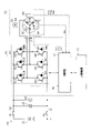
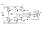
- FIG. 1 is an overall configuration diagram of a control system according to the first embodiment
- FIG. 2 is a functional block diagram of the control device
- FIG. 3 is a diagram showing changes in d- and q-axis current values when three-phase short-circuit control is continued
- FIG. 4 is a diagram showing an example of the waveform of the phase current
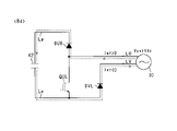
- FIG. 5 is a diagram showing a current path of the first current pattern
- FIG. 6 is a diagram showing a current path of the second current pattern
- FIG. 7 is a diagram showing a current path of the third current pattern
- FIG. 8 is a diagram showing a current path of the fourth current pattern
- FIG. 1 is an overall configuration diagram of a control system according to the first embodiment
- FIG. 2 is a functional block diagram of the control device
- FIG. 3 is a diagram showing changes in d- and q-axis current values when three-phase short-circuit control is continued
- FIG. 4 is a diagram showing an example of the waveform of the phase current
- FIG. 9 is a diagram showing the current path of the fifth current pattern
- FIG. 10 is a diagram showing the current path of the sixth current pattern
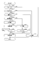
- FIG. 11 is a flowchart showing a control processing procedure performed by the control device
- FIG. 12 is a diagram showing changes in d- and q-axis current values when single-phase short-circuit control is performed
- FIG. 13 is a diagram showing an example of the waveform of the line voltage according to the second embodiment
- FIG. 14 is a diagram showing a current path of the first voltage pattern
- FIG. 15 is a diagram showing current paths of the second voltage pattern
- FIG. 16 is a diagram showing a current path of the third voltage pattern
- FIG. 17 is a diagram showing current paths of the fourth voltage pattern
- FIG. 18 is a diagram showing current paths of the fifth voltage pattern
- FIG. 19 is a diagram showing current paths of the sixth voltage pattern
- FIG. 20 is a flowchart showing a control processing procedure performed by the control device according to the third embodiment
- FIG. 21 is a flowchart showing a control processing procedure performed by the control device according to the fourth embodiment
- FIG. 22 is a flowchart showing a control processing procedure performed by the control device according to the fifth embodiment.
- the control device according to the present embodiment constitutes a control system together with a rotating electric machine as a driving power source, and the control system is mounted on the vehicle.
- the control system 10 includes a storage battery 20 as a DC power supply.
- the storage battery 20 has a terminal voltage (power supply voltage Vdc) of, for example, 100 V or more, and is configured as an assembled battery in which a plurality of battery cells are connected in series.
- the battery cells are, for example, lithium ion storage batteries or nickel metal hydride storage batteries.
- the control system 10 includes a rotating electrical machine 30 and an inverter 40 .
- Inverter 40 electrically connects storage battery 20 and rotating electric machine 30 .
- the rotating electrical machine 30 is a synchronous machine, more specifically a permanent magnet synchronous machine.
- the rotating electric machine 30 has a stator 32 and a rotor 33 .
- the rotating shaft of the rotor 33 is connected to drive wheels of the vehicle via a transmission, a shaft and the like (not shown).
- the stator 32 is provided with U-, V-, and W-phase coils 31U, 31V, and 31W.
- the phase coils 31U, 31V, and 31W are arranged with an electrical angle difference of 120°.
- a permanent magnet 34 is provided on the rotor 33 .
- the inverter 40 has a switching device section 41 .
- the switching device section 41 has three phases of serially connected bodies of upper arm switches QUH, QVH, QWH and lower arm switches QUL, QVL, QWL.
- the switches QUH, QVH, QWH, QUL, QVL, and QWL are voltage-controlled semiconductor switching elements, and more specifically, IGBTs. Therefore, the high potential side terminal of each switch QUH, QVH, QWH, QUL, QVL, QWL is the collector, and the low potential side terminal is the emitter.
- Diodes DUH, DVH, DWH, DUL, DVL, and DWL as freewheel diodes are connected in antiparallel to the switches QUH, QVH, QWH, QUL, QVL, and QWL.
- a first end of a U-phase coil 31U is connected to the emitter of the U-phase upper arm switch QUH and the collector of the U-phase lower arm switch QUL via a U-phase conductive member LU such as a bus bar.
- a first end of a V-phase coil 31V is connected to the emitter of the V-phase upper arm switch QVH and the collector of the V-phase lower arm switch QVL via a V-phase conductive member LV such as a bus bar.
- a first end of a W-phase coil 31W is connected to the emitter of the W-phase upper arm switch QWH and the collector of the W-phase lower arm switch QWL via a W-phase conductive member LW such as a bus bar.
- Second ends of the U-, V-, and W-phase coils 31U, 31V, and 31W are connected at a neutral point O. That is, the coils 31 of each phase are star-connected.
- the number of turns of each phase coil 31U, 31V, and 31W is set to be the same. Thereby, the phase coils 31U, 31V, and 31W are set to have the same inductance, for example.
- the control system 10 includes first and second cut-off switches Sp, Sn.
- each cutoff switch Sp, Sn is a relay (specifically, for example, a system main relay).
- the collectors of the upper arm switches QUH, QVH, QWH and the first end of the first cutoff switch Sp are connected by a positive electrode side bus line Lp such as a bus bar.
- the emitters of the lower arm switches QUL, QVL, QWL and the first end of the second cutoff switch Sn are connected by a negative bus line Ln such as a bus bar.
- the positive terminal of the storage battery 20 is connected to the second end of the first cutoff switch Sp, and the negative terminal of the storage battery 20 is connected to the second end of the second cutoff switch Sn.
- the negative bus line Ln is connected to the ground.
- the inverter 40 has a controller 50 and the control system 10 has a host controller 70 .
- Each cut-off switch Sp, Sn is operated by the controller 50 or the host controller 70 .
- the control system 10 includes a smoothing capacitor 42.
- Smoothing capacitor 42 connects positive electrode side bus line Lp and negative electrode side bus line Ln. Smoothing capacitor 42 may be built in inverter 40 or may be provided outside inverter 40 .
- the storage battery 20 and the smoothing capacitor 42 serve as a power storage unit that supplies the input voltage of the inverter 40 .
- the smoothing capacitor 42 of the storage battery 20 and the smoothing capacitor 42 serves as a power storage unit that supplies the input voltage of the inverter 40 .
- the control system 10 includes a phase current detector 43 , an angle detector 44 and a DC voltage detector 45 .
- the phase current detection unit 43 detects at least two phase currents among the phase currents flowing in the rotating electric machine 30 .
- the sign of the phase current is positive when the current flows from each phase coil 31U, 31V, 31W to the connection point of the series connection of the upper and lower arm switches. It is negative when the current flows from the point to the phase coils 31U, 31V, and 31W.
- the angle detector 44 detects the electrical angle of the rotor 33 and is, for example, a resolver.
- a DC voltage detector 45 detects a power supply voltage, which is a voltage between terminals of the smoothing capacitor 42 . Since the phase coils 31U to 31W are star-connected, the phase current and line current are equal.
- the control system 10 includes a line voltage detection section 46 .
- the line voltage detection unit 46 detects the UV-phase line voltage Vuv between the U-phase coil 31U and the V-phase coil 31V, the V-phase coil 31V and the W-phase coil, using the potential of the negative bus line Ln as a reference voltage (0 V).
- a VW-phase line voltage Vvw between 31W and a WU-phase line voltage Vwu between the W-phase coil 31W and the U-phase coil 31U are detected.
- Detected values of the detectors 43 to 46 are input to the controller 50 .
- the control device 50 corresponds to the "line voltage acquisition section".
- the control device 50 is an ECU (electronic control unit) having a CPU, RAM, ROM, and the like.
- the control device 50 performs power running drive control.
- Powering drive control is switching control of the upper and lower arm switches QUH to QWL for converting the DC power output from the storage battery 20 into AC power and supplying it to the rotary electric machine 30 .
- the rotating electric machine 30 functions as an electric motor and generates a powering torque (>0).
- the control device 50 performs regenerative drive control.
- Regenerative drive control is switching control of upper and lower arm switches QUH to QWL for converting AC power generated by rotary electric machine 30 into DC power and supplying the DC power to storage battery 20 .
- the rotating electric machine 30 functions as a generator and generates regenerative torque ( ⁇ 0).
- FIG. 2 is a functional block diagram of processing executed by the control device 50.
- torque command unit 51 calculates a torque command value Trq* by receiving a command from host control device 70 .
- the current command unit 52 calculates a d-axis current command value Id* and a q-axis current command value Iq* based on the calculated torque command value Trq*.
- the dq conversion unit 53 calculates a d-axis current value Idr and the q-axis current value Iqr.
- the dq conversion unit 53 corresponds to the "dq-axis current acquisition unit" and the "q-axis current acquisition unit”.
- a deviation calculator 54 calculates a d-axis current deviation ⁇ Id that is the difference between the d-axis current command value Id* and the d-axis current value Idr, and a difference q A shaft current deviation ⁇ Iq is calculated.
- the feedback control unit 55 calculates a d-axis voltage command value Vd* as an operation amount for feedback-controlling the d-axis current deviation ⁇ Id to 0, and calculates q as an operation amount for feedback-controlling the q-axis current deviation ⁇ Iq to 0.
- a shaft voltage command value Vq* is calculated.
- Feedback control is, for example, proportional integral control.
- UVW converter 56 converts U-, V- and W-phase voltage command values Vu* and Vv* based on d- and q-axis voltage command values Vd* and Vq* and electrical angle ⁇ e detected by angle detector 44. , Vw*.
- the modulation factor calculator 57 calculates the U-, V-, and W-phase modulation factors based on the U-, V-, and W-phase voltage command values Vu*, Vv*, and Vw* and the power supply voltage Vdc detected by the DC voltage detector 45. Calculate Mu, Mv and Mw.
- the U-phase modulation factor Mu is obtained by dividing the U-phase voltage command value Vu* by the power supply voltage Vdc
- the V-phase modulation factor Mv is obtained by dividing the V-phase voltage command value Vv* by the power supply voltage Vdc
- the W-phase modulation factor Mw is obtained by dividing the W-phase voltage command value Vw* by the power supply voltage Vdc.
- the signal generator 58 generates gate signals for the switches QUH to QWL based on the phase modulation factors Mu, Mv, and Mw calculated by the modulation factor calculator 57 . Specifically, for example, the signal generation unit 58 generates a gate signal based on a magnitude comparison between each modulation factor Mu, Mv, Mw and a carrier signal (for example, a triangular wave signal).
- the gate signal is a signal that instructs to turn on or off each of the switches QUH to QWL, and is input to the switching device section 41 . Thereby, switching control of each of the switches QUH to QWL is performed.
- the control device 50 includes an abnormality determination section 59 and an abnormality control section 60 .
- Abnormality determination unit 59 determines whether an overvoltage abnormality has occurred in smoothing capacitor 42 based on first signal Sg1 and power supply voltage Vdc output from host controller 70, and generates second signal Sg2.
- the first signal Sg1 is a signal for transmitting whether or not an abnormality has occurred in the vehicle
- the second signal Sg2 is a signal for transmitting whether or not an overvoltage abnormality has occurred in the smoothing capacitor 42. is a signal.
- the second signal Sg2 is input to the abnormality control section 60 .
- the abnormality determination unit 59 will be described later.
- the overvoltage abnormality is likely to occur when the permanent magnet 34 has a high magnetic flux density in order to increase the torque of the rotary electric machine 30 . This is because the higher the magnetic flux density of the permanent magnet 34, the higher the back electromotive voltage generated in the coil, and the more likely the smoothing capacitor 42 is applied with an excessively high voltage.
- the intrinsic coercive force is 400 [kA / m] or more, and , a slotless structure having a permanent magnet with a residual magnetic flux density of 1.0 T or more.
- the abnormal control unit 60 generates a shutdown command signal or a three-phase short-circuit command signal based on the second signal Sg2.
- the shutdown command signal is a signal generated when the abnormality control unit 60 determines that the shutdown control to turn off the switches QUH to QWL is to be executed.
- the three-phase short-circuit command signal is generated when the abnormality control unit 60 determines that three-phase short-circuit control is to be performed to turn off the upper arm switches QUH to QWH and turn on the lower arm switches QUL to QWL. signal.
- the shutdown command signal and the three-phase short-circuit command signal are input to the signal generator 58 .
- the abnormal control unit 60 will be described later.
- the three-phase short-circuit control corresponds to "all-phase short-circuit control".
- the signal generator 58 generates a gate signal for turning off the switches QUH to QWL when the shutdown command signal is input. As a result, shutdown control is performed.
- the signal generator 58 When the three-phase short-circuit command signal is input, the signal generator 58 generates gate signals for turning off the upper arm switches QUH to QWH and turning on the lower arm switches QUL to QWL. Thereby, three-phase short-circuit control is performed.
- FIG. 3 shows an example of changes in the d- and q-axis currents Id and Iq when the three-phase short-circuit control is continued.
- the position specified by the d- and q-axis currents Id and Iq in the dq coordinate system of current values will be referred to as an operating point OP.
- the sign of the d-axis current Id is positive when performing field-strengthening, and the sign of the d-axis current Id is negative when performing field-weakening.
- the sign of the q-axis current Iq is positive when the power running torque is generated in the first rotation direction of the rotor 33 by the power running drive control, and the regenerative drive control regenerates in the second rotation direction opposite to the first rotation direction.
- the sign of the q-axis current Iq is negative when torque is generated.
- the operating point OP When the three-phase short-circuit control is executed, return currents flow through the inverter 40 and the phase coils 31U, 31V, and 31W. As shown in FIG. 3, the operating point OP finally reaches the final arrival position M where the q-axis current Iq is the q-axis predetermined value Iq0 and the d-axis current Id is the d-axis predetermined value Id0. converge.
- the q-axis predetermined value Iq0 is approximately 0 when the electrical angular velocity of the rotating electric machine 30 is large.
- the q-axis predetermined value Iq0 is a negative value when the electrical angular velocity of the rotating electric machine 30 is small.
- the d-axis predetermined value Id0 is, for example, when the magnet flux of the permanent magnet 34 and the magnetic flux generated in the phase coils 31U, 31V, and 31W by the d-axis current Id and in the direction of canceling the magnet flux are equal. value.
- the d-axis predetermined value Id0 and the q-axis predetermined value Iq0 are represented by the following equation (e1).
- ⁇ is the magnetic flux of the permanent magnet 34
- R is the resistance value of each phase coil 31U, 31V, 31W
- Ld is the d-axis inductance
- Lq is the q-axis inductance
- ⁇ is the electrical angular velocity of the rotating electric machine 30 .
- the operating point OP does not move linearly from the start position Ps where the three-phase short-circuit control is started to the final reach position M, but draws a trajectory that swirls clockwise around the final reach position M to reach the final position. Go to the arrival position M.
- the trajectory of the operating point OP from the start position Ps to the final arrival position M is sandwiched between the second and third quadrants and the second and third quadrants in the dq coordinate system of the current value. It exists in the d-axis region.
- the second quadrant is a region where the q-axis current Iq has a positive value and the d-axis current Id has a negative value. It is an area where
- the transient d-axis current in the process in which the operating point OP moves toward the final arrival position M intermittently increases in the negative direction.
- the maximum value of the transient d-axis current in the negative direction is indicated as Id1. If the transient d-axis current becomes too large in the negative direction, the permanent magnet 34 may be demagnetized.
- control for suppressing demagnetization of the permanent magnet 34 is performed prior to the implementation of the three-phase short-circuit control.
- the control for suppressing demagnetization of the permanent magnet 34 may complicate the control until the three-phase short-circuit control is implemented.
- the inventors of the present application have decided that the one-phase short-circuit control, which is a simple switching control, is performed in the regenerative driving state in which the rotating electric machine 30 functions as a generator. It was noticed that the magnitude of the transient d-axis current is reduced by
- the abnormality control unit 60 is configured to perform 1-phase short-circuit control before 3-phase short-circuit control is performed in the regenerative drive state.
- One-phase short-circuit control is control in which any one of the switches QUH to QWL is turned on and the remaining switches are turned off. The switching pattern of the one-phase short-circuit control will be described below.
- the abnormality time control unit 60 selects the switch to be turned on in the one-phase short-circuit control among the switches QUH to QWL according to the state of each phase current Iur, Ivr, Iwr.
- FIG. 4 shows an example of the waveforms of the phase currents Iur, Ivr, and Iwr detected by the phase current detector 43 when the rotating electrical machine 30 is in the regenerative drive state.
- the solid line indicates the waveform of the U-phase current Iur
- the dashed line indicates the waveform of the V-phase current Ivr
- the dashed line indicates the waveform of the W-phase current Iwr.
- each phase current Iur, Ivr, Iwr is classified into first to sixth current patterns A1 to A6.
- the phase having the maximum absolute value of the phase current is the U phase, and the U phase current Iur is negative.
- the phase having the maximum absolute value of the phase current among the phases of the switching device section 41 is the V phase, and the V phase current Ivr is positive.
- the phase having the maximum absolute value of the phase current among the phases of the switching device section 41 is the W phase, and the W phase current Iwr is negative.
- the phase having the maximum absolute value of the phase current among the phases of the switching device section 41 is the U phase, and the U phase current Iur is positive.
- the phase having the maximum absolute value of the phase current among the phases of the switching device section 41 is the V phase, and the V phase current Ivr is negative.
- the phase having the maximum absolute value of the phase current among the phases of the switching device section 41 is the W phase, and the W phase current Iwr is positive.
- the abnormal control unit 60 selects the phase having the maximum absolute value of the phase current among the plurality of phases of the switching device unit 41 as the one-phase short-circuit control. Of the upper and lower arms of the selected phase, the abnormal control unit 60 turns on the switch in the arm in which the current does not flow through the diode, and turns off the switch in the arm in which the current flows through the diode. . The abnormal control unit 60 turns off the upper and lower arm switches in the phases other than the phase having the maximum absolute value of the phase current among the plurality of phases of the switching device unit 41 .
- 5 to 10 are diagrams showing current paths flowing through the control system 10 in each of the current patterns A1 to A6. 5 to 10, the configuration shown in FIG. 1 is given the same reference numerals for convenience, and the switches QUH to QWL are turned off.
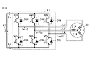
- FIG. 5 shows the current path of the first current pattern A1.
- the current path of the first current pattern A1 is as follows: smoothing capacitor 42 ⁇ negative bus Ln ⁇ U-phase lower arm diode DUL ⁇ U-phase conductive member LU ⁇ U-phase coil 31U ⁇ V, W-phase coils 31V, 31W ⁇ V, W-phase Conductive members LV, LW ⁇ V, W-phase upper arm diodes DVH, DWH ⁇ positive side bus line Lp ⁇ smoothing capacitor 42 .
- the abnormal control unit 60 selects the U phase, turns on the U phase upper arm switch QUH, and turns off the U phase lower arm switch QUL. This forms a closed circuit including the U-phase upper arm switch QUH, the V- and W-phase upper arm diodes DVH and DWH, and the phase coils 31U, 31V and 31W.
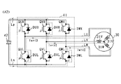
- FIG. 6 shows the current path of the second current pattern A2.
- the current paths of the second current pattern A2 are as follows: smoothing capacitor 42 ⁇ negative bus Ln ⁇ U, W-phase lower arm diodes DUL, DWL ⁇ U, W-phase conductive members LU, LW ⁇ U, W-phase coils 31U, 31W ⁇ V Phase coil 31 V ⁇ V-phase conductive member LV ⁇ V-phase upper arm diode DVH ⁇ positive side bus line Lp ⁇ smoothing capacitor 42 .
- the abnormality control unit 60 selects the V phase, turns on the V phase lower arm switch QVL, and turns off the V phase upper arm switch QVH. This forms a closed circuit including the V-phase lower arm switch QVL, the U- and W-phase lower arm diodes DUL and DWL, and the phase coils 31U, 31V and 31W.
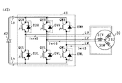
- FIG. 7 shows the current path of the third current pattern A3.
- the current path of the third current pattern A3 is as follows: smoothing capacitor 42 ⁇ negative bus Ln ⁇ W phase lower arm diode DWL ⁇ W phase conductive member LW ⁇ W phase coil 31W ⁇ U, V phase coils 31U, 31V ⁇ U, V phase Conductive members LU, LV ⁇ U, V-phase upper arm diodes DUH, DVH ⁇ positive side bus line Lp ⁇ smoothing capacitor 42 .
- the abnormality control unit 60 selects the W phase, turns on the W phase upper arm switch QWH, and turns off the W phase lower arm switch QWL. This forms a closed circuit including the W-phase upper arm switch QWH, the U- and V-phase upper arm diodes DUH and DVH, and the phase coils 31U, 31V and 31W.
- FIG. 8 shows the current path of the fourth current pattern A4.
- the current path of the fourth current pattern A4 is smoothing capacitor 42 ⁇ negative bus Ln ⁇ V, W-phase lower arm diodes DVL, DWL ⁇ V, W-phase conductive members LV, LW ⁇ V, W-phase coils 31V, 31W ⁇ U.
- the abnormal control unit 60 selects the U phase, turns on the U phase lower arm switch QUL, and turns off the U phase upper arm switch QUH. This forms a closed circuit including the U-phase lower arm switch QUL, the V- and W-phase lower arm diodes DVL and DWL, and the phase coils 31U, 31V and 31W.
- FIG. 9 shows the current path of the fifth current pattern A5.
- the current path of the fifth current pattern A5 is as follows: smoothing capacitor 42 ⁇ negative bus Ln ⁇ V phase lower arm diode DVL ⁇ V phase conductive member LV ⁇ V phase coil 31V ⁇ U, W phase coils 31U, 31W ⁇ U, W phase Conductive members LU, LW ⁇ U, W-phase upper arm diodes DUH, DWH ⁇ positive side bus line Lp ⁇ smoothing capacitor 42 .
- the abnormality control unit 60 selects the V-phase, turns on the V-phase upper arm switch QVH, and turns off the V-phase lower arm switch QVL. This forms a closed circuit including the V-phase upper arm switch QVH, the U- and W-phase upper arm diodes DUH and DWH, and the phase coils 31U, 31V and 31W.
- FIG. 10 shows the current path of the sixth current pattern A6.
- the current path of the sixth current pattern A6 is smoothing capacitor 42 ⁇ negative bus Ln ⁇ U, V-phase lower arm diodes DUL, DVL ⁇ U, V-phase conductive members LU, LV ⁇ U, V-phase coils 31U, 31V ⁇ W.
- the abnormality control unit 60 selects the W phase, turns on the W phase lower arm switch QWL, and performs one-phase short-circuit control to turn off the W phase upper arm switch QWH. This forms a closed circuit including the W-phase lower arm switch QWL, the U- and V-phase lower arm diodes DUL and DVL, and the phase coils 31U, 31V and 31W.
- the abnormal control unit 60 turns on the switches QUH to QWL corresponding to the states of the phase currents Iur, Ivr, and Iwr described above, and issues a one-phase short-circuit command to perform one-phase short-circuit control in which the remaining switches are turned off. Generate a signal.
- the one-phase short-circuit command signal is a signal that is generated when the abnormality control unit 60 determines that one-phase short-circuit control is to be performed.
- a closed circuit including the rotating electric machine 30 and the switching device section 41 is formed. The return current flowing in the closed circuit allows the operating point OP to move towards the operating point where the magnitude of the transient d-axis current is reduced.
- the control device 50 has a configuration for appropriately performing single-phase short-circuit control.
- the host controller 70 determines whether or not an abnormality has occurred in the vehicle. For example, the upper control device 70 may determine that an abnormality has occurred in the vehicle when determining that any one of the following conditions is satisfied.
- the control device 50 has a function of detecting ON/OFF of each of the switches QUH to QWL of the switching device section 41 and notifying the upper control device 70 of the detected information. Based on the information detected by the control device 50, the host control device 70 determines whether or not an abnormality has occurred in the switching device section 41.
- the control device 50 when the host controller 70 determines that an abnormality has occurred in the vehicle, the control device 50 is configured so that the drive signal for each phase output from the signal generator 58 is turned off. there is This configuration can be realized, for example, by instructing the torque command unit 51 from the host controller 70 to stop calculating the torque command value Trq*.
- the host control device 70 also has a function of notifying the driver of the occurrence of an abnormality in the vehicle when it is determined that an abnormality has occurred in the vehicle. As a means of notifying the occurrence of an abnormality in the vehicle, it is conceivable to notify the driver visually or audibly. , or by a voice message.
- the host controller 70 sets the logic of the first signal Sg1 to L when it determines that there is no abnormality in the vehicle, and sets the logic of the first signal Sg1 to H when it determines that there is an abnormality in the vehicle. .
- the first signal Sg ⁇ b>1 is input to the abnormality determination section 59 .
- the abnormality determination unit 59 generates the second signal Sg2 based on the power supply voltage Vdc of the DC voltage detection unit 45 when the logic of the first signal Sg1 is set to H. Specifically, when the logic of the first signal Sg1 is set to H, the abnormality determination unit 59 determines whether or not the power supply voltage Vdc is higher than the overvoltage threshold Vj. When determining that the power supply voltage Vdc is equal to or lower than the overvoltage threshold value Vj, the abnormality determination unit 59 determines that the smoothing capacitor 42 does not have an overvoltage abnormality. In this case, the abnormality determination unit 59 sets the logic of the second signal Sg2 to L.
- the abnormality determination unit 59 determines that the power supply voltage Vdc is higher than the overvoltage threshold value Vj, it determines that an overvoltage abnormality has occurred in the smoothing capacitor 42 . In this case, the abnormality determination unit 59 sets the logic of the second signal Sg2 to H. The second signal Sg2 is input to the abnormality control section 60 .
- the abnormality determination unit 59 does not generate the second signal Sg2 and does not instruct the three-phase short-circuit control and the shutdown control.
- switching control of each of the switches QUH to QWL may be performed based on the gate signal generated by the signal generator 58, for example.
- the abnormality control section 60 determines that shutdown control should be performed. In this case, the abnormality control unit 60 generates a shutdown command signal. The abnormality control unit 60 outputs a shutdown command signal to the signal generation unit 58 .
- the abnormality control section 60 determines that the three-phase short-circuit control is to be performed. In this case, the abnormal control unit 60 generates a three-phase short-circuit command signal. Prior to outputting the three-phase short-circuit command signal to the signal generating section 58, the abnormality control section 60 performs the following control.
- the abnormality control unit 60 determines whether the permanent magnet 34 is demagnetized when the three-phase short-circuit control is performed. judge. Specifically, the abnormality control unit 60 provides correspondence information (for example, , map information or formula information) is used to estimate the magnitude of the transient d-axis current. If the magnitude of the estimated transient d-axis current is greater than or equal to the demagnetization determination value, it is determined that the permanent magnet 34 is demagnetized.
- correspondence information for example, map information or formula information
- the correspondence information and the demagnetization determination value may be set according to the characteristics of the rotating electric machine 30 .
- the abnormality control unit 60 acquires the q-axis current value Iqr calculated by the dq conversion unit 53 .
- the abnormality control unit 60 determines the driving state of the rotating electric machine 30 based on the acquired q-axis current value Iqr. Specifically, when the sign of the q-axis current value Iqr is positive, the abnormality time control unit 60 determines that the rotating electric machine 30 is in a power running state in which it functions as an electric motor. On the other hand, when the sign of the q-axis current value Iqr is negative, the abnormality control unit 60 determines that the rotating electric machine 30 is in a regenerative drive state in which it functions as a generator.
- abnormality control unit 60 determines that the permanent magnet 34 is demagnetized and determines that the rotating electric machine 30 is in the regenerative drive state, it generates a one-phase short-circuit command signal.
- a switching pattern for one-phase short-circuit control is set according to the states of the phase currents Iur, Ivr, and Iwr described above.
- Abnormal control unit 60 outputs a one-phase short-circuit command signal to signal generator 58 prior to the three-phase short-circuit command signal.
- the signal generator 58 turns on one of the switches QUH to QWL based on the one-phase short-circuit command signal and generates a gate signal for turning off the remaining switches. Thereby, the one-phase short-circuit control is performed prior to the three-phase short-circuit control.
- the abnormal time control unit 60 counts the duration after the one-phase short-circuit control is performed, and when it is determined that the duration has reached the first set time Tj1, the three-phase short-circuit command signal is sent to the signal generation unit 58. and output. As a result, the three-phase short-circuit control is performed after the one-phase short-circuit control is temporarily performed.
- the abnormality control unit 60 determines that the permanent magnet 34 is demagnetized and determines that the rotating electrical machine 30 is in the power running state, it generates a shutdown command signal.
- Abnormal control unit 60 outputs a shutdown command signal to signal generation unit 58 prior to the three-phase short-circuit command signal.
- shutdown control is implemented prior to implementation of three-phase short-circuit control.
- the abnormality time control unit 60 determines that the duration time after the shutdown control is performed has reached the second set time Tj2, it outputs a three-phase short-circuit command signal to the signal generation unit 58 .
- the three-phase short-circuit control is performed after the shutdown control is temporarily performed.
- the first and second set times Tj1 and Tj2 may be predetermined in consideration of the characteristics of the rotary electric machine 30, for example.
- FIG. 11 shows the control processing procedure performed by the control device 50 . This control is repeatedly performed at predetermined intervals.
- step S10 the abnormality determination unit 59 determines whether the logic of the first signal Sg1 is H. When determining that the logic of the first signal Sg1 is L, the abnormality determination unit 59 determines that there is no abnormality in the vehicle, and terminates this process. On the other hand, when the abnormality determination unit 59 determines that the logic of the first signal Sg1 is H, it determines that an abnormality has occurred in the vehicle. In this case, abnormality determination unit 59 determines whether an overvoltage abnormality has occurred in smoothing capacitor 42 based on power supply voltage Vdc. The abnormality determination unit 59 generates the second signal Sg2 based on the determination result of the overvoltage abnormality, and outputs the second signal Sg2 to the abnormality time control unit 60 . Then, the process proceeds to step S11.
- step S11 the abnormality control unit 60 determines whether the logic of the second signal Sg2 is H.
- the abnormality control unit 60 determines that the logic of the second signal Sg2 is L, it determines that an overvoltage abnormality does not occur in the smoothing capacitor 42, and proceeds to step S12.
- the abnormality determination unit 59 determines that the logic of the second signal Sg2 is H, it determines that an overvoltage abnormality has occurred in the smoothing capacitor 42, and proceeds to step S13.
- step S11 corresponds to the "overvoltage determination section".
- step S ⁇ b>12 the abnormality control unit 60 generates a shutdown command signal and outputs the shutdown command signal to the signal generation unit 58 .
- the signal generator 58 generates gate signals for turning off the switches QUH to QWL based on the shutdown command signal. As a result, shutdown control is performed.
- step S12 corresponds to the "shutdown control unit".
- step S13 the abnormality control unit 60 demagnetizes the permanent magnet 34 when three-phase short-circuit control is performed based on the d-axis current value Idr and the q-axis current value Iqr calculated by the dq conversion unit 53. Determine whether or not When the abnormality time control unit 60 determines that the permanent magnet 34 is not demagnetized when the three-phase short-circuit control is performed, the process proceeds to step S20 without performing the processes from step S14 to step S19.
- step S ⁇ b>20 the abnormality control unit 60 generates a three-phase short-circuit command signal and outputs the three-phase short-circuit command signal to the signal generation unit 58 .
- the signal generator 58 generates gate signals for turning off the upper arm switches QUH to QWH and turning on the lower arm switches QUL to QWL based on the three-phase short-circuit command signal. Thereby, three-phase short-circuit control is performed.
- step S20 corresponds to the "all-phase short circuit".
- step S13 when the abnormality control unit 60 determines that the permanent magnet 34 is demagnetized when the three-phase short-circuit control is performed, the process proceeds to step S14.
- step S13 corresponds to a "demagnetization determination unit.”
- step S14 the abnormality control unit 60 acquires the q-axis current value Iqr calculated by the dq conversion unit 53. Based on the obtained q-axis current value Iqr, the abnormality control unit 60 determines whether or not the rotating electric machine 30 is in the regenerative driving state. When the abnormality control unit 60 determines that the rotating electrical machine 30 is not in the regenerative driving state, that is, the rotating electrical machine 30 is in the power running driving state, the process proceeds to step S15. It should be noted that in the present embodiment, step S14 corresponds to the "driving state obtaining unit" and the "driving determination unit".
- step S ⁇ b>15 the abnormality control unit 60 generates a shutdown command signal prior to the three-phase short-circuit command signal, and outputs the shutdown command signal to the signal generation unit 58 .
- the signal generator 58 generates gate signals for turning off the switches QUH to QWH based on the shutdown command signal. As a result, shutdown control is performed.
- step S16 the abnormality control unit 60 determines whether or not the duration time since the shutdown control was performed has reached the second set time Tj2.
- the process proceeds to step S20. That is, in this embodiment, the shutdown control is continued only during the second set time Tj2, and then the three-phase short-circuit control is performed.
- step S14 when the abnormality control unit 60 determines that the rotating electric machine 30 is in the regenerative driving state, the process proceeds to step S17.
- step S ⁇ b>17 the abnormality control section 60 generates a shutdown command signal prior to the one-phase short-circuit command signal and outputs the shutdown command signal to the signal generation section 58 .
- the signal generator 58 generates gate signals for turning off the switches QUH to QWH based on the shutdown command signal. As a result, shutdown control is temporarily performed.
- step S ⁇ b>18 the abnormality control unit 60 generates the one-phase short-circuit command signal prior to the three-phase short-circuit command signal, and outputs the one-phase short-circuit command signal to the signal generation unit 58 .
- the abnormality control unit 60 sets the switching pattern for one-phase short-circuit control based on the phase currents Iur, Ivr, and Iwr.
- the signal generator 58 turns on one of the switches QUH to QWL based on the one-phase short-circuit command signal and generates a gate signal for turning off the remaining switches. Thereby, one-phase short-circuit control is performed.
- step S18 corresponds to "one-phase short circuit".
- step S19 the abnormality control unit 60 determines whether or not the duration time since the one-phase short-circuit control has been implemented has reached the first set time Tj1.
- the process proceeds to step S20. That is, in this embodiment, the one-phase short-circuit control is continued for the first set time Tj1, and then the three-phase short-circuit control is performed.
- FIG. 12 shows an example of transition of the operating point OP when one-phase short-circuit control is performed prior to three-phase short-circuit control.
- 1-phase short-circuit control is performed while the operating point OP moves from the start position Ps to the intermediate position Pj
- 3-phase short-circuit control is performed while the operating point OP moves from the intermediate position Pj to the final arrival position M.
- the maximum negative value Id2 of the transient d-axis current of the present embodiment is reduced compared to the maximum negative value Id1 of the transient d-axis current of the comparative example in FIG.
- the operating point OP is compared with the negative maximum value Id1 of the transient d-axis current of the comparative example in FIG.
- the maximum value of the d-axis current in the negative direction increases.
- Tj1 by setting the first set time Tj1 to an appropriate length, an excessive increase in the magnitude of the d-axis current during execution of the one-phase short-circuit control is suppressed.
- the one-phase short-circuit control when the three-phase short-circuit control is performed in the regenerative driving state of the rotating electric machine 30, the one-phase short-circuit control is performed prior to the three-phase short-circuit control. Thereby, a closed circuit including the rotating electric machine 30 and the switching device section 41 is formed.
- the return current flowing in the closed circuit formed by the one-phase short-circuit control allows the operating point OP to move toward the operating point where the magnitude of the transient d-axis current in the negative direction is reduced. Therefore, when the three-phase short-circuit control is performed, the magnitude of the transient d-axis current in the negative direction is reduced, so demagnetization of the permanent magnet 34 can be suppressed.
- the switches QUH-QWL As one-phase short-circuit control, among the switches QUH-QWL, the switches QUH-QWL corresponding to the states of the phase currents Iur, Ivr, and Iwr are turned on, and the remaining switches are turned off. Thereby, a closed circuit including the rotating electric machine 30 and the switching device section 41 is properly formed.
- phase currents Iur, Ivr, and Iwr detected by the phase current detection unit 43 are used for power running drive control or regenerative drive control. Therefore, in the present embodiment, a switch to be turned on is selected based on the phase currents Iur, Ivr, and Iwr in the one-phase short-circuit control. Thereby, one-phase short-circuit control can be performed using the phase currents Iur, Ivr, and Iwr used for powering drive control or regenerative drive control.
- the duration of single-phase short-circuit control is excessively short, the magnitude of the transient d-axis current may not be sufficiently reduced.
- the duration of one-phase short-circuit control is excessively long, the magnitude of the d-axis current may increase. That is, if the duration of the one-phase short-circuit control is not appropriately set, the permanent magnet 34 may be demagnetized.
- the three-phase short-circuit control is performed.
- the duration of the one-phase short-circuit control can be appropriately set, and the magnitude of the transient d-axis current can be appropriately suppressed.
- demagnetization of the permanent magnet 34 can be suppressed accurately.
- a configuration is adopted in which a predetermined time is used as the first set time Tj1.
- a predetermined time is used as the first set time Tj1.
- One-phase short-circuit control is performed on the condition that it is determined that demagnetization of the permanent magnet 34 occurs. Therefore, when it is determined that demagnetization of the permanent magnet 34 does not occur, three-phase short-circuit control is promptly performed without performing one-phase short-circuit control. As a result, while suppressing demagnetization of the permanent magnet 34, it is possible to simplify the control up to the execution of the three-phase short-circuit control.
- Three-phase short-circuit control is performed on the condition that it is determined that an overvoltage abnormality has occurred in the smoothing capacitor 42 . Accordingly, when it is determined that an overvoltage abnormality does not occur in the smoothing capacitor 42, the three-phase short-circuit control is not performed. As a result, the possibility that the permanent magnet 34 is demagnetized can be reduced by executing the three-phase short-circuit control.
- the regenerative driving state is one in which the one-phase short-circuit control should be performed.
- shutdown control is performed prior to the 3-short circuit control.
- the power supply from the switching device section 41 to the rotary electric machine 30 is stopped, so that the operating point OP can be moved toward the operating point at which the transient d-axis current is reduced.
- demagnetization of the permanent magnet 34 can be suppressed.
- FIG. 13 shows an example of waveforms of the line voltages Vuv, Vvw, and Vwu detected by the line voltage detection unit 46 in the regenerative driving state of the rotating electric machine 30.
- the solid line indicates the waveform of the UV-phase line voltage Vuv
- the dashed line indicates the waveform of the VW-phase line voltage Vvw
- the dashed line indicates the waveform of the WU-phase line voltage Vwu.
- the states of the line voltages Vuv, Vvw, and Vwu are classified into first to sixth voltage patterns B1 to B6.
- the first voltage pattern B1 the UV phase line voltage Vuv is lower than the reference voltage.
- the VW-phase line voltage Vvw is higher than the power supply voltage Vdc.
- the WU-phase line voltage Vwu is lower than the reference voltage.
- the UV phase line voltage Vuv is higher than the power supply voltage Vdc.
- the VW-phase line voltage Vvw is lower than the reference voltage.
- the WU-phase line voltage Vwu is higher than the power supply voltage Vdc.
- the power supply voltage Vdc detected by the DC voltage detection unit 45 may be used.
- the abnormal-time control unit 60 controls, among the plurality of phases of the switching device unit 41, the phase in which the current is flowing to the lower arm diode. Turn on the upper arm switch and turn off the lower arm switch.
- the abnormal time control section 60 performs one-phase short-circuit control so that current does not flow through the upper arm diode among the plurality of phases of the switching device section 41 . Turn on the lower arm switch and turn off the upper arm switch in the current phase. It should be noted that the abnormal control section 60 turns off the upper and lower arm switches in phases other than the selected phase among the plurality of phases of the switching device section 41 .
- 14 to 19 are diagrams showing current paths flowing through the control system 10 in each of the voltage patterns B1 to B6. 14 to 19, the illustration of the configuration not used for explanation among the configurations shown in FIG. 1 is omitted, and the configurations shown in FIG. 1 are given the same reference numerals for convenience. ing.
- FIG. 14 shows the current path of the first voltage pattern B1. Since the UV-phase line voltage Vuv becomes lower than the reference voltage, current flows in the direction in which the sign of the U-phase current Iur becomes negative.
- the current path of the first voltage pattern B1 is smoothing capacitor 42 ⁇ negative-side bus Ln ⁇ U-phase lower arm diode DUL ⁇ U-phase conductive member LU ⁇ rotating electric machine 30 ⁇ V-phase conductive member LV ⁇ V-phase upper arm diode DVH ⁇ positive electrode.
- Side bus line Lp ⁇ Smoothing capacitor 42 the abnormal control unit 60 turns on the U-phase upper arm switch QUH and turns off the U-phase lower arm switch QUL in the U-phase in which the current is flowing through the lower arm diode. Thereby, a closed circuit including U-phase upper arm switch QUH, V-phase upper arm diode DVH, and rotating electric machine 30 is formed.
- FIG. 15 shows the current path of the second voltage pattern B2. Since the VW-phase line voltage Vvw becomes higher than the power supply voltage Vdc, current flows in the direction in which the sign of the V-phase current Ivr is positive.
- the current path of the second voltage pattern B2 is smoothing capacitor 42 ⁇ negative-side bus Ln ⁇ W-phase lower arm diode DWL ⁇ W-phase conductive member LW ⁇ rotating electric machine 30 ⁇ V-phase conductive member LV ⁇ V-phase upper arm diode DVH ⁇ positive electrode.
- Side bus line Lp ⁇ Smoothing capacitor 42 is smoothing capacitor 42 ⁇ negative-side bus Ln ⁇ W-phase lower arm diode DWL ⁇ W-phase conductive member LW ⁇ rotating electric machine 30 ⁇ V-phase conductive member LV ⁇ V-phase upper arm diode DVH ⁇ positive electrode.
- the abnormal control unit 60 turns on the V-phase lower arm switch QVL and turns off the V-phase upper arm switch QVH in the V-phase in which current flows through the upper arm diode. Thereby, a closed circuit including V-phase lower arm switch QVL, W-phase lower arm diode DWL, and rotating electric machine 30 is formed.
- FIG. 16 shows the current path of the third voltage pattern B3. Since the WU-phase line voltage Vwu becomes lower than the reference voltage, current flows in the direction in which the sign of the W-phase current Iwr becomes negative.
- the current path of the third voltage pattern B3 is smoothing capacitor 42 ⁇ negative-side bus Ln ⁇ W-phase lower arm diode DWL ⁇ W-phase conductive member LW ⁇ rotating electric machine 30 ⁇ U-phase conductive member LU ⁇ U-phase upper arm diode DUH ⁇ positive electrode. Side bus line Lp ⁇ Smoothing capacitor 42 .
- the abnormal control unit 60 turns on the W-phase upper arm switch QWH and turns off the W-phase lower arm switch QWL in the W-phase in which the current flows through the lower arm diode. Thereby, a closed circuit including W-phase upper arm switch QWH, U-phase upper arm diode DUH, and rotating electric machine 30 is formed.
- FIG. 17 shows the current path of the fourth voltage pattern B4. Since the UV-phase line voltage Vuv is higher than the power supply voltage Vdc, current flows in the direction in which the sign of the U-phase current Iur is positive.
- the current path of the fourth voltage pattern B4 is smoothing capacitor 42 ⁇ negative-side bus Ln ⁇ V-phase lower arm diode DVL ⁇ V-phase conductive member LV ⁇ rotating electric machine 30 ⁇ U-phase conductive member LU ⁇ U-phase upper arm diode DUH ⁇ positive electrode. Side bus line Lp ⁇ Smoothing capacitor 42 .
- the abnormal control unit 60 turns on the U-phase lower arm switch QUL and turns off the U-phase upper arm switch QUH in the U-phase in which current is flowing through the upper arm diode. Thereby, a closed circuit including U-phase lower arm switch QUL, V-phase lower arm diode DVL, and rotating electric machine 30 is formed.
- FIG. 18 shows the current path of the fifth voltage pattern B5. Since the VW-phase line voltage Vvw becomes lower than the reference voltage, current flows in the direction in which the sign of the V-phase current Ivr becomes negative.
- the current path of the fifth voltage pattern B5 is smoothing capacitor 42 ⁇ negative-side bus Ln ⁇ V-phase lower arm diode DVL ⁇ V-phase conductive member LV ⁇ rotating electric machine 30 ⁇ W-phase conductive member LW ⁇ W-phase upper arm diode DWH ⁇ positive electrode. Side bus line Lp ⁇ Smoothing capacitor 42 .
- the abnormal control unit 60 turns on the V-phase upper arm switch QVH and turns off the V-phase lower arm switch QVL in the V-phase in which the current flows through the lower arm diode. Thereby, a closed circuit including V-phase upper arm switch QVH, W-phase upper arm diode DWH, and rotating electric machine 30 is formed.
- FIG. 19 shows the current path of the sixth voltage pattern B6. Since the WU-phase line voltage Vwu becomes higher than the power supply voltage Vdc, current flows in the direction in which the sign of the W-phase current Iwr is positive.
- the current path of the sixth voltage pattern B6 is smoothing capacitor 42 ⁇ negative-side bus Ln ⁇ U-phase lower arm diode DUL ⁇ U-phase conductive member LU ⁇ rotating electric machine 30 ⁇ W-phase conductive member LW ⁇ W-phase upper arm diode DWH ⁇ positive electrode. Side bus line Lp ⁇ Smoothing capacitor 42 .
- the abnormal control unit 60 turns on the W-phase lower arm switch QWL and turns off the W-phase upper arm switch QWH in the W-phase in which the current is flowing through the upper arm diode.
- a closed circuit including W-phase lower arm switch QWL, U-phase lower arm diode DUL, and rotating electric machine 30 is formed.
- a switching pattern for one-phase short-circuit control is selected according to the state of each line voltage Vuv, Vvw, and Vwu.
- the switching pattern for one-phase short-circuit control can be appropriately selected as in the first embodiment.
- the third embodiment will be described below with reference to the drawings, focusing on differences from the first embodiment.
- the d-axis current value Idr and the q-axis current value are used as the first and second set times Tj1 and Tj2.
- the one calculated based on Iqr is used.
- step S21 the abnormal time control unit 60 proceeds to step S21, where the magnitude of the transient d-axis current determines demagnetization based on the d-axis current value Idr and the q-axis current value Iqr.
- a first set time Tj1 is calculated as a set time that is smaller than the value.
- the abnormality control unit 60 uses correspondence information (for example, map information or mathematical expression information) in which the d-axis current value Idr and the q-axis current value Iqr are associated with the first set time Tj1 to obtain the first 1 set time Tj1 is calculated.
- step S19 the abnormality control unit 60 determines whether or not the duration has reached the first set time Tj1 calculated in step S21. It should be noted that in the present embodiment, step S21 corresponds to the "time calculation unit".
- the abnormality control unit 60 proceeds to step S22, and sets the magnitude of the transient d-axis current to be smaller than the demagnetization determination value based on the d-axis current value Idr and the q-axis current value Iqr.
- a second set time Tj2 is calculated.
- the abnormality control unit 60 uses correspondence information (for example, map information or mathematical expression information) in which the d-axis current value Idr and the q-axis current value Iqr are associated with the second set time Tj2 to 2 Calculate the set time Tj2.
- step S16 the abnormality control unit 60 determines whether or not the duration has reached the second set time Tj2 calculated in step S22.
- the first and second set times Tj1 and Tj2 are calculated based on the d-axis current value Idr and the q-axis current value Iqr. Thereby, the duration of the one-phase short-circuit control for suppressing demagnetization of the permanent magnet 34 can be set accurately.
- the fourth embodiment will be described below with reference to the drawings, focusing on differences from the first embodiment.
- the magnitude of the transient d-axis current in the negative direction causes demagnetization of the permanent magnet 34. It is determined whether or not it is within a range that does not occur.
- the abnormality control unit 60 performs the process of step S23 instead of the process of step S19.
- the abnormality control unit 60 estimates the magnitude of the transient d-axis current in the negative direction based on the d-axis current value Idr and the q-axis current value Iqr during execution of the one-phase short-circuit control.
- the abnormality control unit 60 determines whether or not the magnitude of the estimated negative transient d-axis current is within a range in which demagnetization of the permanent magnet 34 does not occur.
- the abnormal-time control unit 60 determines that the magnitude of the transient d-axis current is such that demagnetization of the permanent magnet 34 occurs. Determined to be within range.
- the abnormality control unit 60 sets the magnitude of the transient d-axis current to a range where demagnetization of the permanent magnet 34 does not occur. determined to be within
- the abnormality control unit 60 performs the process of step S24 instead of the process of step S16.
- the abnormality control section 60 may perform the same process as that of step S23. It should be noted that in the present embodiment, the process of step S23 corresponds to the "implementation determination unit".
- the magnitude of the transient d-axis current in the negative direction is within a range where demagnetization of the permanent magnet 34 does not occur. It is determined whether it is within Thereby, the one-phase short-circuit control can be continued until the operating point OP becomes an operating point at which demagnetization of the permanent magnet 34 does not occur. As a result, demagnetization of the permanent magnet 34 can be suppressed.
- the abnormality control unit 60 performs the process of step S25 instead of the process of step S19.
- the abnormality control unit 60 determines whether or not the q-axis current value Iqr during one-phase short-circuit control is zero.
- the abnormal control unit 60 performs the process of step S26 instead of the process of step S16.
- the abnormality control unit 60 may perform the same process as that of step S25. It should be noted that in the present embodiment, the process of step S25 corresponds to the "implementation determination unit".
- the q-axis current value Iqr during execution of one-phase short-circuit control is 0, three-phase short-circuit control is executed.
- the three-phase short-circuit control may be control that turns on the upper arm switches QUH to QWH and turns off the lower arm switches QUL to QWL.
- the abnormality determination unit 59 determines whether or not the power supply voltage Vdc is higher than the overvoltage threshold value Vj. However, it is not limited to this. The abnormality determination unit 59 may determine whether the power supply voltage Vdc is higher than the overvoltage threshold Vj regardless of the logic of the first signal Sg1. When the abnormality determination unit 59 determines that the power supply voltage Vdc is higher than the overvoltage threshold value Vj regardless of the logic of the second signal Sg2, the abnormality control unit 60 determines that an overvoltage abnormality has occurred. The processing of steps S13 to S20 may be performed. Note that in the present embodiment, the processes of steps S10 and S11 may not be performed.
- a load dump such as the first cutoff switch Sp being unintentionally switched to the off state may occur, and an overvoltage abnormality may occur in which the power supply voltage Vdc rises instantaneously. be done.
- one-phase short-circuiting is performed based on the electrical angle ⁇ e of the angle detection unit 44 .
- a switching pattern of controls may be selected.
- step S17 may not be performed.
- the switches that make up the inverter are not limited to IGBTs, but may be, for example, N-channel MOSFETs with built-in body diodes.
- the rotating electric machine and the inverter are not limited to three-phase ones, but may be two-phase ones or four-phase or more ones. Further, the rotating electric machine is not limited to an on-board motor, and may be an in-wheel motor built into a wheel.
- the coils 31 of each phase may be delta-connected.
- the abnormality control unit 60 determines whether or not the q-axis current value Iqr during the one-phase short-circuit control is 0 as the processing of step S25 and the processing of step S26. Instead, it may be determined whether or not the q-axis current value Iqr during execution of the one-phase short-circuit control has been reduced to a current determination value slightly larger than zero.
- the current determination value is a value that can determine that the q-axis current value Iqr during execution of the one-phase short-circuit control is lower than the q-axis current value Iqr before the one-phase short-circuit control is executed. Just do it.
- the mobile object on which the control system is installed is not limited to a vehicle, and may be an aircraft or a ship, for example.
- the rotating electric machine that constitutes the control system serves as the flight power source of the aircraft.
- the rotating electric machine that constitutes the control system serves as the navigation power source of the ship.
- control unit and techniques described in this disclosure can be performed by a dedicated computer provided by configuring a processor and memory programmed to perform one or more functions embodied by a computer program; may be implemented.
- the controls and techniques described in this disclosure may be implemented by a dedicated computer provided by configuring the processor with one or more dedicated hardware logic circuits.
- the control units and techniques described in this disclosure can be implemented by a combination of a processor and memory programmed to perform one or more functions and a processor configured by one or more hardware logic circuits. It may also be implemented by one or more dedicated computers configured.
- the computer program may also be stored as computer-executable instructions on a computer-readable non-transitional tangible recording medium.
Landscapes
- Engineering & Computer Science (AREA)
- Power Engineering (AREA)
- Control Of Ac Motors In General (AREA)
- Control Of Electric Motors In General (AREA)
- Inverter Devices (AREA)
Abstract
制御装置(50)は、永久磁石(34)を有するロータ(33)、及びコイル(31U,31V,31W)を有するステータ(32)を備える回転電機(30)と、ダイオード(DUH,DVH,DWH,DUL,DVL,DWL)が逆並列接続された上,下アームスイッチ(QUH,QVH,QWH,QUL,QVL,QWL)を有するインバータ(40)と、を備えるシステム(10)に適用される。制御装置は、上,下アームスイッチのうち、一方のアームスイッチを全相オンするとともに他方のアームスイッチを全相オフする全相短絡制御を実施する全相短絡部と、回生駆動状態において、全相短絡制御が実施されるのに先立ち、複数相の上,下アームスイッチのうち1相における一方のアームスイッチをオンするとともに他方のアームスイッチをオフし、残りの相における上,下アームスイッチをオフする1相短絡制御を実施する1相短絡部と、を備える。
Description
本出願は、2021年1月22日に出願された日本出願番号2021-008624号に基づくもので、ここにその記載内容を援用する。
本開示は、回転電機の制御装置に関する。
従来、回転電機と、インバータとを備えるシステムが知られている。回転電機は、永久磁石を有するロータと、複数相のコイルを有するステータとを備える。インバータは、各相毎に上,下アームスイッチを有し、コイルに電気的に接続される。例えば特許文献1には、上述したシステムに適用される回転電機の制御装置として、上,下アームスイッチのうち、一方のアームスイッチを全相オンし、かつ、他方のアームスイッチを全相オフする全相短絡制御を実施するものが記載されている。
全相短絡制御が実施された場合、dq座標系においてd,q軸電流値で特定される動作点は、d軸電流値が弱め界磁側の所定値になる最終到達位置に収束する。この場合、動作点は、全相短絡制御の開始時における動作点から最終到達位置に直線的に向かうのではなく、最終到達位置を中心に渦を巻く軌跡を描いて最終到達位置に向かう。最終到達位置に向かう過程において、d軸電流は、弱め界磁側に断続的に大きくなる。d軸電流が弱め界磁側に過剰に大きくなる場合、永久磁石が減磁される可能性がある。
永久磁石が減磁されるのを抑制するための制御により、全相短絡制御が実施されるまでの制御が複雑化し得る。例えば、特許文献1では、全相短絡制御が実施されるのに先立ち、全相短絡制御の実施後のd軸電流が低減されるように、d,q軸電流指令値が変更され、変更されたd,q軸電流指令値にd,q軸電流を制御すべく、上,下アームスイッチのスイッチング制御が行われる。この場合、全相短絡制御が実施されるまでに、d,q軸電流指令値の変更と、スイッチング制御とを実施する必要があり、全相短絡制御が実施されるまでの制御が複雑化する。
本開示は、上記事情に鑑みてなされたものであり、その主たる目的は、簡素な制御により、永久磁石が減磁されるのを抑制することができる回転電機の制御装置を提供することである。
本開示は、永久磁石を有するロータ、及び複数相のコイルを有するステータを備える回転電機と、ダイオードが逆並列接続された上,下アームスイッチを有し、該上,下アームスイッチ及び前記コイルを電気的に接続するインバータと、を備えるシステムに適用される回転電機の制御装置において、前記上,下アームスイッチのうち、一方のアームスイッチを全相オンするとともに他方のアームスイッチを全相オフする全相短絡制御を実施する全相短絡部と、前記回転電機が発電機として機能する回生駆動状態において、前記全相短絡制御が実施されるのに先立ち、複数相の前記上,下アームスイッチのうち1相における一方のアームスイッチをオンするとともに他方のアームスイッチをオフし、残りの相における上,下アームスイッチをオフする1相短絡制御を実施する1相短絡部と、を備える。
本願発明者は、全相短絡制御を実施するまでの制御が複雑化することに鑑み、簡易なスイッチング制御である1相短絡制御が実施されることにより、全相短絡制御が実施された場合の弱め界磁側のd軸電流が低減されることに着目した。
そこで、本開示では、回生駆動状態において、全相短絡制御が実施されるのに先立ち、1相短絡制御が実施される。これにより、オンされた1相分のアームスイッチと、ダイオードと、コイルとを含む閉回路に還流電流が流れる。還流電流が流れることにより、全相短絡制御が実施された場合における弱め界磁側のd軸電流が低減されるように、dq座標系においてd,q軸電流値で特定される動作点を変化させることができる。そのため、その後全相短絡制御が実施された場合の弱め界磁側のd軸電流が低減され、永久磁石が減磁されるのを抑制できる。このように、本開示によれば、1相短絡制御を一時的に実施するといった簡素な制御により、永久磁石が減磁されるのを抑制することができる。
本開示についての上記目的およびその他の目的、特徴や利点は、添付の図面を参照しながら下記の詳細な記述により、より明確になる。その図面は、
図1は、第1実施形態に係る制御システムの全体構成図であり、
図2は、制御装置の機能ブロック図であり、
図3は、3相短絡制御が継続された場合のd,q軸電流値の推移を示す図であり、
図4は、相電流の波形の一例を示す図であり、
図5は、第1電流パターンの電流経路を示す図であり、
図6は、第2電流パターンの電流経路を示す図であり、
図7は、第3電流パターンの電流経路を示す図であり、
図8は、第4電流パターンの電流経路を示す図であり、
図9は、第5電流パターンの電流経路を示す図であり、
図10は、第6電流パターンの電流経路を示す図であり、
図11は、制御装置が実施する制御の処理手順を示すフローチャートであり、
図12は、1相短絡制御が実施された場合のd,q軸電流値の推移を示す図であり、
図13は、第2実施形態に係る線間電圧の波形の一例を示す図であり、
図14は、第1電圧パターンの電流経路を示す図であり、
図15は、第2電圧パターンの電流経路を示す図であり、
図16は、第3電圧パターンの電流経路を示す図であり、
図17は、第4電圧パターンの電流経路を示す図であり、
図18は、第5電圧パターンの電流経路を示す図であり、
図19は、第6電圧パターンの電流経路を示す図であり、
図20は、第3実施形態に係る制御装置が実施する制御の処理手順を示すフローチャートであり、
図21は、第4実施形態に係る制御装置が実施する制御の処理手順を示すフローチャートであり、
図22は、第5実施形態に係る制御装置が実施する制御の処理手順を示すフローチャートである。
<第1実施形態>
以下、本開示に係る制御装置を具体化した第1実施形態について、図面を参照しつつ説明する。本実施形態に係る制御装置は、走行動力源としての回転電機とともに制御システムを構成し、制御システムは車両に搭載されている。
以下、本開示に係る制御装置を具体化した第1実施形態について、図面を参照しつつ説明する。本実施形態に係る制御装置は、走行動力源としての回転電機とともに制御システムを構成し、制御システムは車両に搭載されている。
図1に示すように、制御システム10は、直流電源としての蓄電池20を備えている。蓄電池20は、例えば百V以上となる端子間電圧(電源電圧Vdc)を有し、複数の電池セルが直列接続された組電池として構成されている。電池セルは、例えばリチウムイオン蓄電池又はニッケル水素蓄電池である。
制御システム10は、回転電機30及びインバータ40を備えている。インバータ40は、蓄電池20及び回転電機30を電気的に接続する。回転電機30は、同期機であり、より具体的には永久磁石同期機である。
回転電機30は、ステータ32及びロータ33を備えている。ロータ33の回転軸は、図示しない変速機及びシャフト等を介して、車両の駆動輪に接続されている。ステータ32には、U,V,W相コイル31U,31V,31Wが設けられている。各相コイル31U,31V,31Wは、電気角で120°ずつずれて配置されている。ロータ33には、永久磁石34が設けられている。
インバータ40は、スイッチングデバイス部41を備えている。スイッチングデバイス部41は、上アームスイッチQUH,QVH,QWHと下アームスイッチQUL,QVL,QWLとの直列接続体を3相分備えている。本実施形態では、各スイッチQUH,QVH,QWH,QUL,QVL,QWLとして、電圧制御形の半導体スイッチング素子が用いられており、具体的にはIGBTが用いられている。このため、各スイッチQUH,QVH,QWH,QUL,QVL,QWLの高電位側端子はコレクタであり、低電位側端子はエミッタである。各スイッチQUH,QVH,QWH,QUL,QVL,QWLには、フリーホイールダイオードとしての各ダイオードDUH,DVH,DWH,DUL,DVL,DWLが逆並列に接続されている。
U相上アームスイッチQUHのエミッタと、U相下アームスイッチQULのコレクタとには、バスバー等のU相導電部材LUを介して、U相コイル31Uの第1端が接続されている。V相上アームスイッチQVHのエミッタと、V相下アームスイッチQVLのコレクタとには、バスバー等のV相導電部材LVを介して、V相コイル31Vの第1端が接続されている。W相上アームスイッチQWHのエミッタと、W相下アームスイッチQWLのコレクタとには、バスバー等のW相導電部材LWを介して、W相コイル31Wの第1端が接続されている。U,V,W相コイル31U,31V,31Wの第2端同士は、中性点Oで接続されている。すなわち、各相のコイル31は、スター結線されている。なお、本実施形態において、各相コイル31U,31V,31Wは、ターン数が同じに設定されている。これにより、各相コイル31U,31V,31Wは、例えばインダクタンスが同じに設定されている。
制御システム10は、第1,第2遮断スイッチSp,Snを備えている。本実施形態において、各遮断スイッチSp,Snは、リレー(具体的には例えば、システムメインリレー)である。各上アームスイッチQUH,QVH,QWHのコレクタと、第1遮断スイッチSpの第1端とは、バスバー等の正極側母線Lpにより接続されている。各下アームスイッチQUL,QVL,QWLのエミッタと、第2遮断スイッチSnの第1端とは、バスバー等の負極側母線Lnにより接続されている。第1遮断スイッチSpの第2端には、蓄電池20の正極端子が接続され、第2遮断スイッチSnの第2端には、蓄電池20の負極端子が接続されている。本実施形態では、負極側母線Lnがグランドに接続されている。
インバータ40は、制御装置50を備えており、制御システム10は、上位制御装置70を備えている。各遮断スイッチSp,Snは、制御装置50又は上位制御装置70により操作される。
制御システム10は、平滑コンデンサ42を備えている。平滑コンデンサ42は、正極側母線Lpと負極側母線Lnとを接続する。なお、平滑コンデンサ42は、インバータ40に内蔵されていてもよいし、インバータ40の外部に設けられていてもよい。
各遮断スイッチSp,Snがオンされている場合、蓄電池20及び平滑コンデンサ42が、インバータ40の入力電圧を供給する蓄電部となる。一方、各遮断スイッチSp,Snがオフされている場合、蓄電池20及び平滑コンデンサ42のうち平滑コンデンサ42が、インバータ40の入力電圧を供給する蓄電部となる。
制御システム10は、相電流検出部43、角度検出部44及び直流電圧検出部45を備えている。相電流検出部43は、回転電機30に流れる各相電流のうち、少なくとも2相分の相電流を検出する。相電流の符号は、各相コイル31U,31V,31Wから各上,下アームスイッチの直列接続体の接続点へと電流が流れる場合を正とし、各上,下アームスイッチの直列接続体の接続点から各相コイル31U,31V,31Wへと電流が流れる場合を負とする。角度検出部44は、ロータ33の電気角を検出し、例えばレゾルバである。直流電圧検出部45は、平滑コンデンサ42の端子間電圧である電源電圧を検出する。なお、各相コイル31U~31Wはスター結線されているため、相電流と線電流とは等しい。
制御システム10は、線間電圧検出部46を備えている。線間電圧検出部46は、負極側母線Lnの電位を基準電圧(0V)として、U相コイル31U及びV相コイル31Vの間のUV相線間電圧Vuvと、V相コイル31V及びW相コイル31Wの間のVW相線間電圧Vvwと、W相コイル31W及びU相コイル31Uの間のWU相線間電圧Vwuとを検出する。各検出部43~46の検出値は、制御装置50に入力される。本実施形態において、制御装置50が「線間電圧取得部」に相当する。
制御装置50は、CPU、RAM,ROM等を有するECU(電子制御ユニット)である。制御装置50は、力行駆動制御を行う。力行駆動制御は、蓄電池20から出力される直流電力を交流電力に変換して回転電機30に供給するための各上,下アームスイッチQUH~QWLのスイッチング制御である。力行駆動制御が行われる場合、回転電機30は、電動機として機能し、力行トルク(>0)を発生する。また、制御装置50は、回生駆動制御を行う。回生駆動制御は、回転電機30で発電される交流電力を直流電力に変換して蓄電池20に供給するための各上,下アームスイッチQUH~QWLのスイッチング制御である。回生駆動制御が行われる場合、回転電機30は、発電機として機能し、回生トルク(<0)を発生する。
図2は、制御装置50が実行する処理の機能ブロック図である。制御装置50において、トルク指令部51は、上位制御装置70から指令を受けることにより、トルク指令値Trq*を算出する。電流指令部52は、算出されたトルク指令値Trq*に基づいて、d軸電流指令値Id*及びq軸電流指令値Iq*を算出する。
dq変換部53は、相電流検出部43により検出された各相電流Iur,Ivr,Iwrと、角度検出部44により検出された電気角θeとに基づいて、dq座標系におけるd軸電流値Idr及びq軸電流値Iqrを算出する。なお、本実施形態において、dq変換部53が「dq軸電流取得部」及び「q軸電流取得部」に相当する。
偏差演算部54は、d軸電流指令値Id*とd軸電流値Idrとの差であるd軸電流偏差ΔIdと、q軸電流指令値Iq*とq軸電流値Iqrとの差であるq軸電流偏差ΔIqとを算出する。
フィードバック制御部55は、d軸電流偏差ΔIdを0にフィードバック制御するための操作量としてd軸電圧指令値Vd*を算出し、q軸電流偏差ΔIqを0にフィードバック制御するための操作量としてq軸電圧指令値Vq*を算出する。フィードバック制御は、例えば、比例積分制御である。
UVW変換部56は、d,q軸電圧指令値Vd*,Vq*と、角度検出部44により検出された電気角θeとに基づいて、U,V,W相電圧指令値Vu*,Vv*,Vw*を算出する。
変調率算出部57は、U,V,W相電圧指令値Vu*,Vv*,Vw*と、直流電圧検出部45により検出された電源電圧Vdcに基づいて、U,V,W相変調率Mu,Mv,Mwを算出する。ここで、U相変調率Muは、U相電圧指令値Vu*を電源電圧Vdcで除算したものであり、V相変調率Mvは、V相電圧指令値Vv*を電源電圧Vdcで除算したものであり、W相変調率Mwは、W相電圧指令値Vw*を電源電圧Vdcで除算したものである。
信号生成部58は、変調率算出部57により算出された各相変調率Mu,Mv,Mwに基づいて、各スイッチQUH~QWLのゲート信号を生成する。具体的には例えば、信号生成部58は、各変調率Mu,Mv,Mwとキャリア信号(例えば三角波信号)との大小比較に基づいて、ゲート信号を生成する。ここで、ゲート信号は、各スイッチQUH~QWLのオン又はオフを指示する信号であり、スイッチングデバイス部41に入力される。これにより、各スイッチQUH~QWLのスイッチング制御が実施される。
制御装置50は、異常判定部59及び異常時制御部60を備えている。異常判定部59は、上位制御装置70から出力される第1信号Sg1及び電源電圧Vdcに基づいて、平滑コンデンサ42に過電圧異常が発生したか否かを判定し、第2信号Sg2を生成する。ここで、第1信号Sg1は、車両に異常が発生したか否かを伝達するための信号であり、第2信号Sg2は、平滑コンデンサ42に過電圧異常が発生したか否かを伝達するための信号である。第2信号Sg2は、異常時制御部60に入力される。なお、異常判定部59については後述する。
過電圧異常は、回転電機30の高トルク化を図るために、永久磁石34が高磁束密度を有するものである場合に発生しやすい。これは、永久磁石34が高磁束密度であるほど、コイルに発生する逆起電圧が高くなりやすく、平滑コンデンサ42に過度な高電圧が印加されやすいためである。なお、高トルク化が図られた回転電機としては、具体的には例えば、特開2019-106866号公報に記載されているように、固有保磁力が400[kA/m]以上であり、かつ、残留磁束密度が1.0T以上の永久磁石を有するスロットレス構造のものがある。
異常時制御部60は、第2信号Sg2に基づいて、シャットダウン指令信号又は3相短絡指令信号を生成する。ここで、シャットダウン指令信号とは、各スイッチQUH~QWLをオフするシャットダウン制御を実施すると異常時制御部60により判定された場合に生成される信号である。3相短絡指令信号とは、各上アームスイッチQUH~QWHをオフするとともに、各下アームスイッチQUL~QWLをオンする3相短絡制御を実施すると異常時制御部60により判定された場合に生成される信号である。シャットダウン指令信号及び3相短絡指令信号は信号生成部58に入力される。なお、異常時制御部60については後述する。本実施形態において、3相短絡制御が「全相短絡制御」に相当する。
信号生成部58は、シャットダウン指令信号が入力された場合、各スイッチQUH~QWLをオフするゲート信号を生成する。これにより、シャットダウン制御が実施される。信号生成部58は、3相短絡指令信号が入力された場合、各上アームスイッチQUH~QWHをオフするとともに、各下アームスイッチQUL~QWLをオンするゲート信号を生成する。これにより、3相短絡制御が実施される。
図3に、3相短絡制御が継続された場合におけるd,q軸電流Id,Iqの推移の一例を示す。以下では、電流値のdq座標系においてd,q軸電流Id,Iqで特定される位置を動作点OPと称すこととする。また、本実施形態では、強め界磁を行う場合のd軸電流Idの符号を正とし、弱め界磁を行う場合のd軸電流Idの符号を負とする。また、力行駆動制御によりロータ33の第1回転方向に力行トルクを発生させる場合のq軸電流Iqの符号を正とし、回生駆動制御により第1回転方向とは逆方向の第2回転方向に回生トルクを発生させる場合におけるq軸電流Iqの符号を負とする。
3相短絡制御が実行されると、インバータ40及び各相コイル31U,31V,31Wに還流電流が流れるようになる。図3に示すように、動作点OPは、最終的には、q軸電流Iqがq軸所定値Iq0であって、かつ、d軸電流Idがd軸所定値Id0になる最終到達位置Mに収束する。q軸所定値Iq0は、回転電機30の電気角速度が大きい場合、ほぼ0の値となる。一方、q軸所定値Iq0は、回転電機30の電気角速度が小さい場合、負側の値となる。d軸所定値Id0は、例えば、永久磁石34の磁石磁束と、d軸電流Idにより各相コイル31U,31V,31Wに発生する磁束であって磁石磁束を打ち消す方向の磁束とが等しくなる場合の値である。詳しくは、d軸所定値Id0及びq軸所定値Iq0は下式(e1)で表される。

動作点OPは、3相短絡制御が開始される開始位置Psから最終到達位置Mに直線的に向かうのではなく、最終到達位置Mを中心に時計回りに渦を巻くような軌跡を描いて最終到達位置Mに向かう。図3に示す例では、開始位置Psから最終到達位置Mに向かうまでの動作点OPの軌跡が、電流値のdq座標系において第2,第3象限及び第2,第3象限に挟まれたd軸の領域に存在している。第2象限とは、q軸電流Iqが正の値となり、d軸電流Idが負の値となる領域であり、第3象限とは、d,q軸電流Id,Iqがともに負の値となる領域である。
3相短絡制御の実施中において、動作点OPが最終到達位置Mに向かう過程の過渡d軸電流は、負方向に断続的に大きくなる。図3では、過渡d軸電流の負方向の最大値をId1として示している。過渡d軸電流が負方向に過剰に大きくなる場合、永久磁石34が減磁される可能性がある。
従来、3相短絡制御の実施に先立ち、永久磁石34の減磁を抑制するための制御が実施されている。しかし、永久磁石34が減磁されるのを抑制するための制御により、3相短絡制御が実施されるまでの制御が複雑化し得る。本願発明者は、3相短絡制御が実施されるまでの制御が複雑化することに鑑み、回転電機30が発電機として機能する回生駆動状態において、簡易なスイッチング制御である1相短絡制御が実施されることにより、過渡d軸電流の大きさが低減されることに着目した。
そこで、本実施形態では、異常時制御部60は、回生駆動状態において、3相短絡制御が実施されるのに先立ち1相短絡制御が実施される構成を備えることとした。1相短絡制御とは、各スイッチQUH~QWLのうちいずれか1つのスイッチがオンされるとともに、残りのスイッチがオフされる制御である。以下、1相短絡制御のスイッチングパターンについて説明する。
異常時制御部60は、各スイッチQUH~QWLのうち1相短絡制御においてオンするスイッチを、各相電流Iur,Ivr,Iwrの状態に応じて選択する。図4は、回転電機30の回生駆動状態において、相電流検出部43により検出される各相電流Iur,Ivr,Iwrの波形の一例である。図4において、実線はU相電流Iurの波形を示し、破線はV相電流Ivrの波形を示し、一点鎖線はW相電流Iwrの波形を示す。
各相電流Iur,Ivr,Iwrの状態は、第1~第6電流パターンA1~A6に区分される。詳しくは、第1電流パターンA1では、スイッチングデバイス部41の各相のうち相電流の絶対値が最大となる相がU相とされ、かつ、U相電流Iurが負とされる。第2電流パターンA2では、スイッチングデバイス部41の各相のうち相電流の絶対値が最大となる相がV相とされ、かつ、V相電流Ivrが正とされる。第3電流パターンA3では、スイッチングデバイス部41の各相のうち相電流の絶対値が最大となる相がW相とされ、かつ、W相電流Iwrが負とされる。第4電流パターンA4では、スイッチングデバイス部41の各相のうち相電流の絶対値が最大となる相がU相とされ、かつ、U相電流Iurが正とされる。第5電流パターンA5では、スイッチングデバイス部41の各相のうち相電流の絶対値が最大となる相がV相とされ、かつ、V相電流Ivrが負とされる。第6電流パターンA6では、スイッチングデバイス部41の各相のうち相電流の絶対値が最大となる相がW相とされ、かつ、W相電流Iwrが正とされる。
異常時制御部60は、1相短絡制御として、スイッチングデバイス部41の複数相のうち、相電流の絶対値が最大となる相を選択する。異常時制御部60は、選択した相における上,下アームのうち、ダイオードに電流が流れていない方のアームにおけるスイッチをオンするとともに、ダイオードに電流が流れている方のアームにおけるスイッチをオフする。なお、異常時制御部60は、スイッチングデバイス部41の複数相のうち、相電流の絶対値が最大となる相以外の相において、上,下アームスイッチをオフする。
図5~10は、各電流パターンA1~A6において、制御システム10に流れる電流経路を示す図である。なお、図5~10において、先の図1に示した構成については、便宜上、同一の符号を付しており、各スイッチQUH~QWLはオフされている。
図5は、第1電流パターンA1の電流経路である。第1電流パターンA1の電流経路は、平滑コンデンサ42→負極側母線Ln→U相下アームダイオードDUL→U相導電部材LU→U相コイル31U→V,W相コイル31V,31W→V,W相導電部材LV,LW→V,W相上アームダイオードDVH,DWH→正極側母線Lp→平滑コンデンサ42となる。この場合、異常時制御部60は、U相を選択し、U相上アームスイッチQUHをオンするとともにU相下アームスイッチQULをオフする。これにより、U相上アームスイッチQUHと、V,W相上アームダイオードDVH,DWHと、各相コイル31U,31V,31Wとを含む閉回路が形成される。
図6は、第2電流パターンA2の電流経路である。第2電流パターンA2の電流経路は、平滑コンデンサ42→負極側母線Ln→U,W相下アームダイオードDUL,DWL→U,W相導電部材LU,LW→U,W相コイル31U,31W→V相コイル31V→V相導電部材LV→V相上アームダイオードDVH→正極側母線Lp→平滑コンデンサ42となる。この場合、異常時制御部60は、V相を選択し、V相下アームスイッチQVLをオンするとともにV相上アームスイッチQVHをオフする。これにより、V相下アームスイッチQVLと、U,W相下アームダイオードDUL,DWLと、各相コイル31U,31V,31Wとを含む閉回路が形成される。
図7は、第3電流パターンA3の電流経路である。第3電流パターンA3の電流経路は、平滑コンデンサ42→負極側母線Ln→W相下アームダイオードDWL→W相導電部材LW→W相コイル31W→U,V相コイル31U,31V→U,V相導電部材LU,LV→U,V相上アームダイオードDUH,DVH→正極側母線Lp→平滑コンデンサ42となる。この場合、異常時制御部60は、W相を選択し、W相上アームスイッチQWHをオンするとともにW相下アームスイッチQWLをオフする。これにより、W相上アームスイッチQWHと、U,V相上アームダイオードDUH,DVHと、各相コイル31U,31V,31Wとを含む閉回路が形成される。
図8は、第4電流パターンA4の電流経路である。第4電流パターンA4の電流経路は、平滑コンデンサ42→負極側母線Ln→V,W相下アームダイオードDVL,DWL→V,W相導電部材LV,LW→V,W相コイル31V,31W→U相コイル31U→U相導電部材LU→U相上アームダイオードDUH→正極側母線Lp→平滑コンデンサ42となる。この場合、異常時制御部60は、U相を選択し、U相下アームスイッチQULをオンするとともにU相上アームスイッチQUHをオフする。これにより、U相下アームスイッチQULと、V,W相下アームダイオードDVL,DWLと、各相コイル31U,31V,31Wとを含む閉回路が形成される。
図9は、第5電流パターンA5の電流経路である。第5電流パターンA5の電流経路は、平滑コンデンサ42→負極側母線Ln→V相下アームダイオードDVL→V相導電部材LV→V相コイル31V→U,W相コイル31U,31W→U,W相導電部材LU,LW→U,W相上アームダイオードDUH,DWH→正極側母線Lp→平滑コンデンサ42となる。この場合、異常時制御部60は、V相を選択し、V相上アームスイッチQVHをオンするとともにV相下アームスイッチQVLをオフする。これにより、V相上アームスイッチQVHと、U,W相上アームダイオードDUH,DWHと、各相コイル31U,31V,31Wとを含む閉回路が形成される。
図10は、第6電流パターンA6の電流経路である。第6電流パターンA6の電流経路は、平滑コンデンサ42→負極側母線Ln→U,V相下アームダイオードDUL,DVL→U,V相導電部材LU,LV→U,V相コイル31U,31V→W相コイル31W→W相導電部材LW→W相上アームダイオードDWH→正極側母線Lp→平滑コンデンサ42となる。この場合、異常時制御部60は、W相を選択し、W相下アームスイッチQWLをオンするとともに、W相上アームスイッチQWHをオフする1相短絡制御を実施する。これにより、W相下アームスイッチQWLと、U,V相下アームダイオードDUL,DVLと、各相コイル31U,31V,31Wとを含む閉回路が形成される。
異常時制御部60は、上述した各相電流Iur,Ivr,Iwrの状態に対応するスイッチQUH~QWLをオンするとともに、残りのスイッチをオフする1相短絡制御を実施すべく、1相短絡指令信号を生成する。ここで、1相短絡指令信号とは、1相短絡制御を実施すると異常時制御部60により判定された場合に生成される信号である。これにより、1相短絡制御が実施された場合、回転電機30及びスイッチングデバイス部41を含む閉回路が形成される。閉回路に還流電流が流れることにより、動作点OPを、過渡d軸電流の大きさが低減される動作点に向かわせることができる。
制御装置50は、1相短絡制御を適切に実施するための構成を備えている。
上位制御装置70は、車両に異常が発生したか否かを判定する。例えば、上位制御装置70は、以下の条件のうちいずれか1つが成立したと判定した場合、車両に異常が発生したと判定すればよい。
・車両が衝突してエアバックが作動したとの条件
・車両が他車両に牽引されているとの条件
・制御システム10に異常が発生したとの条件
制御システム10の異常には、回転電機30及びインバータ40のうち少なくとも1つの異常が含まれる。本実施形態では、制御装置50は、スイッチングデバイス部41の各スイッチQUH~QWLのオンオフを検出し、検出された情報を上位制御装置70に通知する機能を有している。上位制御装置70は、制御装置50により検出された情報に基づいて、スイッチングデバイス部41に異常が発生したか否かを判定する。
・車両が他車両に牽引されているとの条件
・制御システム10に異常が発生したとの条件
制御システム10の異常には、回転電機30及びインバータ40のうち少なくとも1つの異常が含まれる。本実施形態では、制御装置50は、スイッチングデバイス部41の各スイッチQUH~QWLのオンオフを検出し、検出された情報を上位制御装置70に通知する機能を有している。上位制御装置70は、制御装置50により検出された情報に基づいて、スイッチングデバイス部41に異常が発生したか否かを判定する。
本実施形態では、上位制御装置70により車両に異常が発生したと判定された場合、制御装置50において、信号生成部58から出力される各相の駆動信号がオフ指令になるように構成されている。この構成は、例えば、上位制御装置70からトルク指令部51に対して、トルク指令値Trq*の算出の停止を指示することにより実現できる。また、上位制御装置70は、車両に異常が発生したと判定した場合、車両に異常が発生した旨を運転者に通知する機能を有している。車両に異常が発生した旨の通知手段としては、視覚や聴覚により運転者への通知を行うことが考えられ、具体的にはインストルメントパネル等の表示部にメッセージを表示することで通知したり、或いは音声メッセージにより通知したりする。
上位制御装置70は、車両に異常が発生していないと判定した場合、第1信号Sg1の論理をLにし、車両に異常が発生したと判定した場合、第1信号Sg1の論理をHにする。第1信号Sg1は、異常判定部59に入力される。
異常判定部59は、第1信号Sg1の論理がHとされた場合、直流電圧検出部45の電源電圧Vdcに基づいて、第2信号Sg2を生成する。詳しくは、異常判定部59は、第1信号Sg1の論理がHとされた場合、電源電圧Vdcが過電圧閾値Vjよりも高いか否かを判定する。異常判定部59は、電源電圧Vdcが過電圧閾値Vj以下であると判定した場合、平滑コンデンサ42に過電圧異常が発生してないと判定する。この場合、異常判定部59は第2信号Sg2の論理をLにする。一方、異常判定部59は、電源電圧Vdcが過電圧閾値Vjよりも高いと判定した場合、平滑コンデンサ42に過電圧異常が発生したと判定する。この場合、異常判定部59は第2信号Sg2の論理をHにする。第2信号Sg2は、異常時制御部60に入力される。
なお、異常判定部59は、第1信号Sg1の論理がLとされた場合、第2信号Sg2を生成せず、3相短絡制御及びシャットダウン制御の指示を行わない。この場合、例えば、信号生成部58により生成されたゲート信号に基づいて、各スイッチQUH~QWLのスイッチング制御が行われればよい。
異常時制御部60は、第2信号Sg2の論理がLとされた場合、シャットダウン制御を実施すると判定する。この場合、異常時制御部60は、シャットダウン指令信号を生成する。異常時制御部60は、シャットダウン指令信号を信号生成部58に出力する。
異常時制御部60は、第2信号Sg2の論理がHとされた場合、3相短絡制御を実施すると判定する。この場合、異常時制御部60は、3相短絡指令信号を生成する。異常時制御部60は、3相短絡指令信号を信号生成部58に出力するのに先立ち、以下の制御を行う。
異常時制御部60は、dq変換部53により算出されたd軸電流値Idr及びq軸電流値Iqrに基づいて、3相短絡制御を実施した場合に永久磁石34が減磁するか否かを判定する。具体的には、異常時制御部60は、d軸電流値Idr及びq軸電流値Iqrと、3相短絡制御を実施した場合の過渡d軸電流の大きさとが対応付けられた対応情報(例えば、マップ情報又は数式情報)を用いて、過渡d軸電流の大きさを推定する。推定された過渡d軸電流の大きさが減磁判定値以上の場合、永久磁石34が減磁すると判定する。一方、推定された過渡d軸電流の大きさが所定値未満の場合、永久磁石34が減磁しないと判定する。なお、対応情報及び減磁判定値は、回転電機30の特性に応じて設定されればよい。
異常時制御部60は、dq変換部53により算出されたq軸電流値Iqrを取得する。異常時制御部60は取得したq軸電流値Iqrに基づいて、回転電機30の駆動状態を判定する。詳しくは、異常時制御部60は、q軸電流値Iqrの符号が正の場合、回転電機30が電動機として機能する力行駆動状態であると判定する。一方、異常時制御部60は、q軸電流値Iqrの符号が負の場合、回転電機30が発電機として機能する回生駆動状態であると判定する。
異常時制御部60は、永久磁石34が減磁すると判定し、かつ、回転電機30が回生駆動状態であると判定した場合、1相短絡指令信号を生成する。1相短絡制御のスイッチングパターンは、上述した各相電流Iur,Ivr,Iwrの状態に応じて設定される。異常時制御部60は、3相短絡指令信号よりも先に、1相短絡指令信号を信号生成部58へと出力する。
信号生成部58は、1相短絡指令信号に基づいて、各スイッチQUH~QWLのうちいずれか1つのスイッチをオンするとともに、残りのスイッチをオフするゲート信号を生成する。これにより、3相短絡制御の実施に先立ち、1相短絡制御が実施される。
異常時制御部60は、1相短絡制御が実施されてからの継続時間をカウントし、継続時間が第1設定時間Tj1に到達したと判定した場合、3相短絡指令信号を信号生成部58へと出力する。これにより、1相短絡制御が一時的に実施された後、3相短絡制御が実施される。
なお、異常時制御部60は、永久磁石34が減磁すると判定し、かつ、回転電機30が力行駆動状態であると判定した場合、シャットダウン指令信号を生成する。異常時制御部60は、3相短絡指令信号よりも先に、シャットダウン指令信号を信号生成部58へと出力する。この場合、3相短絡制御の実施に先立ち、シャットダウン制御が実施される。異常時制御部60は、シャットダウン制御が実施されてからの継続時間が第2設定時間Tj2に到達したと判定した場合、3相短絡指令信号を信号生成部58へと出力する。これにより、シャットダウン制御が一時的に実施された後、3相短絡制御が実施される。本実施形態において、第1,第2設定時間Tj1,Tj2は、例えば回転電機30の特性等を考慮し、予め定められたものを用いればよい。
図11に、制御装置50が実施する制御の処理手順を示す。この制御は、所定周期毎に繰り返し実施される。
ステップS10では、異常判定部59は、第1信号Sg1の論理がHであるか否かを判定する。異常判定部59は、第1信号Sg1の論理がLであると判定した場合、車両に異常が発生してないと判定するとともに、本処理を終了する。一方、異常判定部59は、第1信号Sg1の論理がHであると判定した場合、車両に異常が発生したと判定する。この場合、異常判定部59は、電源電圧Vdcに基づいて、平滑コンデンサ42に過電圧異常が発生したか否かを判定する。異常判定部59は、過電圧異常の判定結果に基づいて、第2信号Sg2を生成するとともに、第2信号Sg2を異常時制御部60に出力する。そして、ステップS11に進む。
ステップS11では、異常時制御部60は、第2信号Sg2の論理がHであるか否かを判定する。異常時制御部60は、第2信号Sg2の論理がLであると判定した場合、平滑コンデンサ42に過電圧異常が発生してないと判定するとともに、ステップS12に進む。一方、異常判定部59は、第2信号Sg2の論理がHであると判定した場合、平滑コンデンサ42に過電圧異常が発生したと判定するとともに、ステップS13に進む。なお、本実施形態において、ステップS11が「過電圧判定部」に相当する。
ステップS12では、異常時制御部60は、シャットダウン指令信号を生成するとともに、シャットダウン指令信号を信号生成部58に出力する。信号生成部58は、シャットダウン指令信号に基づいて、各スイッチQUH~QWLをオフするゲート信号を生成する。これにより、シャットダウン制御が実施される。なお、本実施形態において、ステップS12が「シャットダウン制御部」に相当する。
ステップS13では、異常時制御部60は、dq変換部53により算出されたd軸電流値Idr及びq軸電流値Iqrに基づいて、3相短絡制御を実施した場合に永久磁石34が減磁するか否かを判定する。異常時制御部60は、3相短絡制御を実施した場合に永久磁石34が減磁しないと判定した場合、ステップS14からステップS19までの処理を行わずに、ステップS20に進む。
ステップS20では、異常時制御部60は、3相短絡指令信号を生成するとともに、3相短絡指令信号を信号生成部58に出力する。信号生成部58は、3相短絡指令信号に基づいて、各上アームスイッチQUH~QWHをオフするとともに、各下アームスイッチQUL~QWLをオンするゲート信号を生成する。これにより、3相短絡制御が実施される。本実施形態において、ステップS20が「全相短絡部」に相当する。
一方、ステップS13において、異常時制御部60は、3相短絡制御を実施した場合に永久磁石34が減磁すると判定した場合、ステップS14に進む。なお、本実施形態において、ステップS13が「減磁判定部」に相当する。
ステップS14では、異常時制御部60は、dq変換部53により算出されたq軸電流値Iqrを取得する。異常時制御部60は、取得したq軸電流値Iqrに基づいて、回転電機30が回生駆動状態であるか否かを判定する。異常時制御部60は、回転電機30が回生駆動状態でない、すなわち回転電機30が力行駆動状態であると判定した場合、ステップS15に進む。なお、本実施形態において、ステップS14が「駆動状態取得部」及び「駆動判定部」に相当する。
ステップS15では、異常時制御部60は、3相短絡指令信号よりも先にシャットダウン指令信号を生成するとともに、シャットダウン指令信号を信号生成部58に出力する。信号生成部58は、シャットダウン指令信号に基づいて、各スイッチQUH~QWHをオフするゲート信号を生成する。これにより、シャットダウン制御が実施される。
ステップS16では、異常時制御部60は、シャットダウン制御が実施されてからの継続時間が第2設定時間Tj2に到達したか否かを判定する。異常時制御部60は、継続時間が第2設定時間Tj2に到達したと判定した場合、ステップS20に進む。つまり、本実施形態では、シャットダウン制御が第2設定時間Tj2の間だけ継続され、その後3相短絡制御が実施される。
一方、ステップS14において、異常時制御部60は、回転電機30が回生駆動状態であると判定した場合、ステップS17に進む。
ステップS17では、異常時制御部60は、1相短絡指令信号よりも先にシャットダウン指令信号を生成するとともに、シャットダウン指令信号を信号生成部58に出力する。信号生成部58は、シャットダウン指令信号に基づいて、各スイッチQUH~QWHをオフするゲート信号を生成する。これにより、シャットダウン制御が一時的に実施される。
ステップS18では、異常時制御部60は、3相短絡指令信号よりも先に1相短絡指令信号を生成するとともに、1相短絡指令信号を信号生成部58に出力する。本実施形態において、異常時制御部60は、各相電流Iur,Ivr,Iwrに基づいて、1相短絡制御のスイッチングパターンを設定する。信号生成部58は、1相短絡指令信号に基づいて、各スイッチQUH~QWLのうちいずれか1つのスイッチをオンするとともに、残りのスイッチをオフするゲート信号を生成する。これにより、1相短絡制御が実施される。本実施形態において、ステップS18が「1相短絡部」に相当する。
ステップS19では、異常時制御部60は、1相短絡制御が実施されてからの継続時間が第1設定時間Tj1に到達したか否かを判定する。異常時制御部60は、継続時間が第1設定時間Tj1に到達したと判定した場合、ステップS20に進む。つまり、本実施形態では、1相短絡制御が第1設定時間Tj1の間だけ継続され、その後3相短絡制御が実施される。
図12に、3相短絡制御の実施に先立ち、1相短絡制御が実施された場合における動作点OPの推移の一例を示す。動作点OPが、開始位置Psから中間位置Pjまで向かう間において、1相短絡制御が実施され、中間位置Pjから最終到達位置Mまで向かう間において、3相短絡制御が実施される。この場合、先の図3における比較例の過渡d軸電流の負方向の最大値Id1と比較して、本実施形態の過渡d軸電流の負方向の最大値Id2が低減される。
なお、1相短絡制御が過度に長く実施された場合、動作点OPは、先の図3における比較例の過渡d軸電流の負方向の最大値Id1と比較して、1相短絡制御の実施中におけるd軸電流の負方向の最大値が増大してしまう。本実施形態では、第1設定時間Tj1を適切な長さに設定することにより、1相短絡制御の実施中におけるd軸電流の大きさが過度に増大することを抑制している。
以上詳述した本実施形態によれば、以下の効果が得られるようになる。
本実施形態では、回転電機30の回生駆動状態において、3相短絡制御が実施される場合、3相短絡制御が実施されるのに先立ち、1相短絡制御が実施される。これにより、回転電機30及びスイッチングデバイス部41を含む閉回路が形成される。1相短絡制御により形成される閉回路に還流電流が流れることにより、動作点OPを、負方向の過渡d軸電流の大きさが低減される動作点に向かわせることができる。そのため、3相短絡制御が実施された場合、負方向の過渡d軸電流の大きさが低減されるため、永久磁石34が減磁されるのを抑制できる。このように、本実施形態によれば、1相短絡制御を一時的に実施するといった簡素な制御により、永久磁石34が減磁されるのを抑制することができる。
1相短絡制御として、各スイッチQUH~QWLのうち、各相電流Iur,Ivr,Iwrの状態に対応するスイッチQUH~QWLがオンされるとともに、残りのスイッチがオフされる。これにより、回転電機30及びスイッチングデバイス部41を含む閉回路が的確に形成される。
相電流検出部43が検出した各相電流Iur,Ivr,Iwrは、力行駆動制御又は回生駆動制御の実施に用いられる。そこで、本実施形態では、1相短絡制御において、各相電流Iur,Ivr,Iwrに基づいて、オンされるスイッチが選択される構成とした。これにより、力行駆動制御又は回生駆動制御の実施に用いられる各相電流Iur,Ivr,Iwrを利用して、1相短絡制御を実施することができる。
1相短絡制御の継続時間が過度に短い場合、過渡d軸電流の大きさが十分に低減されない可能性がある。一方、1相短絡制御の継続時間が過度に長い場合、d軸電流の大きさが増大する可能性がある。つまり、1相短絡制御の継続時間が適切に設定されない場合、永久磁石34が減磁される可能性がある。
そこで、本実施形態では、1相短絡制御の継続時間が第1設定時間Tj1に到達したと判定された場合、3相短絡制御が実施される構成とした。これにより、1相短絡制御の継続時間を適切に設定でき、過渡d軸電流の大きさを的確に抑制することができる。その結果、永久磁石34が減磁するのを的確に抑制することができる。
第1設定時間Tj1として、予め定められたものを用いる構成とした。これにより、第1設定時間Tj1を状況に応じて都度設定するための処理を行わずに、簡易に1相短絡制御を実施することができる。
永久磁石34の減磁が発生すると判定されたことを条件として、1相短絡制御が実施される。そのため、永久磁石34の減磁が発生しないと判定された場合、1相短絡制御が実施されずに、速やかに3相短絡制御が実施される。その結果、永久磁石34が減磁されるのを抑制しつつ、3相短絡制御を実施するまでの制御を簡素化することができる。
平滑コンデンサ42に過電圧異常が発生すると判定されたことを条件として、3相短絡制御が実施される。これにより、平滑コンデンサ42に過電圧異常が発生しないと判定された場合、3相短絡制御が実施されない。その結果、3相短絡制御が実施されることにより、永久磁石34が減磁される可能性を低減することができる。
dq変換部53により算出されたq軸電流値Iqrに基づいて、回転電機30の駆動状態が回生駆動状態であるか否かが判定される。そのため、1相短絡制御が実施されるべき回生駆動状態であることを的確に判定することができる。
回転電機30の駆動状態が力行駆動状態であると判定された場合、3短絡制御が実施されるのに先立ち、シャットダウン制御が実施される。これにより、スイッチングデバイス部41から回転電機30への電力供給が停止されるため、動作点OPを、過渡d軸電流が低減される動作点に向かわせることができる。その結果、永久磁石34が減磁するのを抑制することができる。
1相短絡制御が実施されるのに先立ち、シャットダウン制御が実施される。これにより、正極側母線Lpと負極側母線Lnとが短絡されることを抑制することができる。
<第2実施形態>
以下、第2実施形態について、第1実施形態との相違点を中心に図面を参照しつつ説明する。本実施形態では、各相電流Iur,Ivr,Iwrの状態に応じて1相短絡制御のスイッチングパターンが選択されるのに代えて、各線間電圧Vuv,Vvw,Vwuの状態に応じて1相短絡制御のスイッチングパターンが選択される。
以下、第2実施形態について、第1実施形態との相違点を中心に図面を参照しつつ説明する。本実施形態では、各相電流Iur,Ivr,Iwrの状態に応じて1相短絡制御のスイッチングパターンが選択されるのに代えて、各線間電圧Vuv,Vvw,Vwuの状態に応じて1相短絡制御のスイッチングパターンが選択される。
図13は、回転電機30の回生駆動状態において、線間電圧検出部46により検出された各線間電圧Vuv,Vvw,Vwuの波形の一例である。図13において、実線はUV相線間電圧Vuvの波形を示し、破線はVW相線間電圧Vvwの波形を示し、一点鎖線はWU相線間電圧Vwuの波形を示す。
各線間電圧Vuv,Vvw,Vwuの状態は、第1~第6電圧パターンB1~B6に区分される。詳しくは、第1電圧パターンB1では、UV相線間電圧Vuvが基準電圧よりも低くなる。第2電圧パターンB2では、VW相線間電圧Vvwが電源電圧Vdcよりも高くなる。第3電圧パターンB3では、WU相線間電圧Vwuが基準電圧よりも低くなる。第4電圧パターンB4では、UV相線間電圧Vuvが電源電圧Vdcよりも高くなる。第5電圧パターンB5では、VW相線間電圧Vvwが基準電圧よりも低くなる。第6電圧パターンB6では、WU相線間電圧Vwuが電源電圧Vdcよりも高くなる。なお、電源電圧Vdcは、直流電圧検出部45により検出されたものを用いればよい。
異常時制御部60は、1相短絡制御として、各線間電圧Vuv,Vvw,Vwuが基準電圧よりも低い場合、スイッチングデバイス部41の複数相のうち、下アームダイオードに電流が流れている相における上アームスイッチをオンするとともに、下アームスイッチをオフする。一方、異常時制御部60は、1相短絡制御として、各線間電圧Vuv,Vvw,Vwuが電源電圧Vdcよりも高い場合、スイッチングデバイス部41の複数相のうち、上アームダイオードに電流が流れている相における下アームスイッチをオンするとともに、上アームスイッチをオフする。なお、異常時制御部60は、スイッチングデバイス部41の複数相のうち、選択された相以外の相において、上,下アームスイッチをオフする。
図14~19は、各電圧バターンB1~B6において、制御システム10に流れる電流経路を示す図である。なお、図14~19において、先の図1に示した構成のうち説明に用いない構成の図示を省略しており、先の図1に示した構成については、便宜上、同一の符号を付している。
図14は、第1電圧パターンB1の電流経路である。UV相線間電圧Vuvが基準電圧よりも低くなるため、U相電流Iurの符号が負となる向きに電流が流れる。第1電圧パターンB1の電流経路は、平滑コンデンサ42→負極側母線Ln→U相下アームダイオードDUL→U相導電部材LU→回転電機30→V相導電部材LV→V相上アームダイオードDVH→正極側母線Lp→平滑コンデンサ42となる。この場合、異常時制御部60は、下アームダイオードに電流が流れているU相において、U相上アームスイッチQUHをオンするとともに、U相下アームスイッチQULをオフする。これにより、U相上アームスイッチQUHと、V相上アームダイオードDVHと、回転電機30とを含む閉回路が形成される。
図15は、第2電圧パターンB2の電流経路である。VW相線間電圧Vvwが電源電圧Vdcよりも高くなるため、V相電流Ivrの符号が正となる向きに電流が流れる。第2電圧パターンB2の電流経路は、平滑コンデンサ42→負極側母線Ln→W相下アームダイオードDWL→W相導電部材LW→回転電機30→V相導電部材LV→V相上アームダイオードDVH→正極側母線Lp→平滑コンデンサ42となる。この場合、異常時制御部60は、上アームダイオードに電流が流れているV相において、V相下アームスイッチQVLをオンするとともに、V相上アームスイッチQVHをオフする。これにより、V相下アームスイッチQVLと、W相下アームダイオードDWLと、回転電機30とを含む閉回路が形成される。
図16は、第3電圧パターンB3の電流経路である。WU相線間電圧Vwuが基準電圧よりも低くなるため、W相電流Iwrの符号が負となる向きに電流が流れる。第3電圧パターンB3の電流経路は、平滑コンデンサ42→負極側母線Ln→W相下アームダイオードDWL→W相導電部材LW→回転電機30→U相導電部材LU→U相上アームダイオードDUH→正極側母線Lp→平滑コンデンサ42となる。この場合、異常時制御部60は、下アームダイオードに電流が流れているW相において、W相上アームスイッチQWHをオンするとともに、W相下アームスイッチQWLをオフする。これにより、W相上アームスイッチQWHと、U相上アームダイオードDUHと、回転電機30とを含む閉回路が形成される。
図17は、第4電圧パターンB4の電流経路である。UV相線間電圧Vuvが電源電圧Vdcよりも高くなるため、U相電流Iurの符号が正となる向きに電流が流れる。第4電圧パターンB4の電流経路は、平滑コンデンサ42→負極側母線Ln→V相下アームダイオードDVL→V相導電部材LV→回転電機30→U相導電部材LU→U相上アームダイオードDUH→正極側母線Lp→平滑コンデンサ42となる。この場合、異常時制御部60は、上アームダイオードに電流が流れているU相において、U相下アームスイッチQULをオンするとともに、U相上アームスイッチQUHをオフする。これにより、U相下アームスイッチQULと、V相下アームダイオードDVLと、回転電機30とを含む閉回路が形成される。
図18は、第5電圧パターンB5の電流経路である。VW相線間電圧Vvwが基準電圧よりも低くなるため、V相電流Ivrの符号が負となる向きに電流が流れる。第5電圧パターンB5の電流経路は、平滑コンデンサ42→負極側母線Ln→V相下アームダイオードDVL→V相導電部材LV→回転電機30→W相導電部材LW→W相上アームダイオードDWH→正極側母線Lp→平滑コンデンサ42となる。この場合、異常時制御部60は、下アームダイオードに電流が流れているV相において、V相上アームスイッチQVHをオンするとともに、V相下アームスイッチQVLをオフする。これにより、V相上アームスイッチQVHと、W相上アームダイオードDWHと、回転電機30とを含む閉回路が形成される。
図19は、第6電圧パターンB6の電流経路である。WU相線間電圧Vwuが電源電圧Vdcよりも高くなるため、W相電流Iwrの符号が正となる向きに電流が流れる。第6電圧パターンB6の電流経路は、平滑コンデンサ42→負極側母線Ln→U相下アームダイオードDUL→U相導電部材LU→回転電機30→W相導電部材LW→W相上アームダイオードDWH→正極側母線Lp→平滑コンデンサ42となる。この場合、異常時制御部60は、上アームダイオードに電流が流れているW相において、W相下アームスイッチQWLをオンするとともに、W相上アームスイッチQWHをオフする。これにより、W相下アームスイッチQWLと、U相下アームダイオードDULと、回転電機30とを含む閉回路が形成される。
本実施形態では、各線間電圧Vuv,Vvw,Vwuの状態に応じて、1相短絡制御のスイッチングパターンが選択される構成とした。これにより、第1実施形態と同様に、1相短絡制御のスイッチングパターンを的確に選択することができる。
<第3実施形態>
以下、第3実施形態について、第1実施形態との相違点を中心に図面を参照しつつ説明する。本実施形態では、第1,第2設定時間Tj1,Tj2として予め定められたものが用いられるのに代えて、第1,第2設定時間Tj1,Tj2としてd軸電流値Idr及びq軸電流値Iqrに基づいて算出されたものが用いられる。
以下、第3実施形態について、第1実施形態との相違点を中心に図面を参照しつつ説明する。本実施形態では、第1,第2設定時間Tj1,Tj2として予め定められたものが用いられるのに代えて、第1,第2設定時間Tj1,Tj2としてd軸電流値Idr及びq軸電流値Iqrに基づいて算出されたものが用いられる。
図20に示すように、異常時制御部60は、ステップS18の後、ステップS21に進み、d軸電流値Idr及びq軸電流値Iqrに基づいて、過渡d軸電流の大きさが減磁判定値より小さくなるような設定時間として、第1設定時間Tj1を算出する。詳しくは、異常時制御部60は、d軸電流値Idr及びq軸電流値Iqrと、第1設定時間Tj1とが対応付けられた対応情報(例えば、マップ情報又は数式情報)を用いて、第1設定時間Tj1を算出する。ステップS19では、異常時制御部60は、継続時間がステップS21において算出された第1設定時間Tj1に到達したか否かを判定する。なお、本実施形態において、ステップS21が「時間算出部」に相当する。
異常時制御部60は、ステップS15の後、ステップS22に進み、d軸電流値Idr及びq軸電流値Iqrに基づいて、過渡d軸電流の大きさが減磁判定値より小さくなるような設定時間として、第2設定時間Tj2を算出する。詳しくは、異常時制御部60は、d軸電流値Idr及びq軸電流値Iqrと、第2設定時間Tj2とが対応付けられた対応情報(例えば、マップ情報又は数式情報)を用いて、第2設定時間Tj2を算出する。ステップS16では、異常時制御部60は、継続時間がステップS22において算出された第2設定時間Tj2に到達したか否かを判定する。
本実施形態では、d軸電流値Idr及びq軸電流値Iqrに基づいて、第1,第2設定時間Tj1,Tj2が算出される。これにより、永久磁石34の減磁を抑制するための1相短絡制御の継続時間を的確に設定することができる。
<第4実施形態>
以下、第4実施形態について、第1実施形態との相違点を中心に図面を参照しつつ説明する。本実施形態では、1相短絡制御の継続時間が設定時間に到達したか否かが判定されるのに代えて、負方向の過渡d軸電流の大きさが、永久磁石34の減磁が発生しない範囲内であるか否かが判定される。
以下、第4実施形態について、第1実施形態との相違点を中心に図面を参照しつつ説明する。本実施形態では、1相短絡制御の継続時間が設定時間に到達したか否かが判定されるのに代えて、負方向の過渡d軸電流の大きさが、永久磁石34の減磁が発生しない範囲内であるか否かが判定される。
図21に示すように、異常時制御部60は、ステップS19の処理に代えて、ステップS23の処理を行う。ステップS23において、異常時制御部60は、1相短絡制御の実施中のd軸電流値Idr及びq軸電流値Iqrに基づいて、負方向の過渡d軸電流の大きさを推定する。異常時制御部60は、推定された負方向の過渡d軸電流の大きさが、永久磁石34の減磁が発生しない範囲内であるか否かを判定する。詳しくは、異常時制御部60は、推定された負方向の過渡d軸電流の大きさが減磁判定値以上の場合、過渡d軸電流の大きさが、永久磁石34の減磁が発生する範囲内であると判定する。一方、異常時制御部60は、推定された負方向の過渡d軸電流の大きさが減磁判定値未満の場合、過渡d軸電流の大きさが、永久磁石34の減磁が発生しない範囲内であると判定する。
異常時制御部60は、ステップS16の処理に代えて、ステップS24の処理を行う。異常時制御部60は、ステップS24の処理として、ステップS23と同様の処理を行えばよい。なお、本実施形態において、ステップS23の処理が「実施判定部」に相当する。
本実施形態では、1相短絡制御の実施中におけるd軸電流値Idr及びq軸電流値Iqrに基づいて、負方向の過渡d軸電流の大きさが、永久磁石34の減磁が発生しない範囲内であるか否かが判定される。これにより、動作点OPが、永久磁石34の減磁が発生しない動作点になるまで、1相短絡制御を継続できる。その結果、永久磁石34が減磁するのを抑制することができる。
<第5実施形態>
以下、第5実施形態について、第1実施形態との相違点を中心に図面を参照しつつ説明する。本実施形態では、1相短絡制御の継続時間が設定時間に到達したか否かが判定されるのに代えて、q軸電流値Iqrが0であるか否かが判定される。
以下、第5実施形態について、第1実施形態との相違点を中心に図面を参照しつつ説明する。本実施形態では、1相短絡制御の継続時間が設定時間に到達したか否かが判定されるのに代えて、q軸電流値Iqrが0であるか否かが判定される。
図22に示すように、異常時制御部60は、ステップS19の処理に代えて、ステップS25の処理を行う。ステップS25において、異常時制御部60は、1相短絡制御の実施中のq軸電流値Iqrが0であるか否かを判定する。
異常時制御部60は、ステップS16の処理に代えて、ステップS26の処理を行う。異常時制御部60は、ステップS26の処理として、ステップS25と同様の処理を行えばよい。なお、本実施形態において、ステップS25の処理が「実施判定部」に相当する。
本実施形態では、1相短絡制御の実施中のq軸電流値Iqrが0であると判定された場合、3相短絡制御が実施される。ここで、3相短絡制御が実施される前におけるq軸電流値Iqrの大きさが小さいほど、過渡d軸電流が低減されることが知られている。そのため、q軸電流値Iqrが0の状態において3相短絡制御が実施されることにより、過渡d軸電流を低減することができ、ひいては、永久磁石34が減磁するのを抑制することができる。
<その他の実施形態>
なお、上記各実施形態は、以下のように変更して実施してもよい。
なお、上記各実施形態は、以下のように変更して実施してもよい。
・3相短絡制御は、各上アームスイッチQUH~QWHをオンするとともに、各下アームスイッチQUL~QWLをオフする制御であってもよい。
・第1実施形態において、異常判定部59は、上位制御装置70から通知される第1信号Sg1の論理がHとされた場合、電源電圧Vdcが過電圧閾値Vjよりも高いか否かを判定するとしたが、これに限られない。異常判定部59は、第1信号Sg1の論理にかかわらず、電源電圧Vdcが過電圧閾値Vjよりも高いか否かを判定してもよい。また、異常時制御部60は、第2信号Sg2の論理にかかわらず、異常判定部59により電源電圧Vdcが過電圧閾値Vjよりも高いと判定された場合、過電圧異常が発生したと判定するとともに、ステップS13~ステップS20の処理を行ってもよい。なお、本実施形態において、ステップS10及びステップS11の処理は行われなくてもよい。
例えば、回転電機30の力行駆動制御中において、第1遮断スイッチSpが意図せずオフ状態に切り替えられる等のロードダンプが発生し、電源電圧Vdcが瞬時に上昇する過電圧異常が発生することが考えられる。この点、本実施形態では、上位制御装置70を介さずに過電圧異常が発生したか否かが判定されるため、速やかに3相短絡制御を実施することができる。
・第1実施形態において、各相電流Iur,Ivr,Iwrの状態に応じて1相短絡制御のスイッチングパターンが選択されることに代えて、角度検出部44の電気角θeに基づいて1相短絡制御のスイッチングパターンが選択されてもよい。
・ステップS17の処理は行われなくてもよい。
・インバータを構成するスイッチとしては、IGBTに限らず、例えば、ボディダイオードを内蔵するNチャネルMOSFETであってもよい。
・回転電機及びインバータとしては、3相のものに限らず、2相のもの、又は4相以上のものであってもよい。また、回転電機としては、オンボード用のモータに限らず、車輪に内蔵されるインホイールモータであってもよい。
・各相のコイル31がスター結線されることに代えて、各相のコイル31がデルタ結線されていてもよい。
・第5実施形態において、異常時制御部60は、ステップS25の処理及びステップS26の処理として、1相短絡制御の実施中のq軸電流値Iqrが0であるか否かを判定する処理に代えて、1相短絡制御の実施中のq軸電流値Iqrが0よりもやや大きい電流判定値まで低減されたか否かを判定する処理を行ってもよい。ここで、電流判定値は、1相短絡制御の実施中のq軸電流値Iqrが、1相短絡制御が実施される前のq軸電流値Iqrよりも低減されたことを判定できる値であればよい。
・制御システムが搭載される移動体としては、車両に限らず、例えば、航空機又は船舶であってもよい。例えば、移動体が航空機の場合、制御システムを構成する回転電機は航空機の飛行動力源となる。また、例えば、移動体が船舶の場合、制御システムを構成する回転電機は船舶の航行動力源となる。
・本開示に記載の制御部及びその手法は、コンピュータプログラムにより具体化された一つ乃至は複数の機能を実行するようにプログラムされたプロセッサ及びメモリを構成することによって提供された専用コンピュータにより、実現されてもよい。あるいは、本開示に記載の制御部及びその手法は、一つ以上の専用ハードウエア論理回路によってプロセッサを構成することによって提供された専用コンピュータにより、実現されてもよい。もしくは、本開示に記載の制御部及びその手法は、一つ乃至は複数の機能を実行するようにプログラムされたプロセッサ及びメモリと一つ以上のハードウエア論理回路によって構成されたプロセッサとの組み合わせにより構成された一つ以上の専用コンピュータにより、実現されてもよい。また、コンピュータプログラムは、コンピュータにより実行されるインストラクションとして、コンピュータ読み取り可能な非遷移有形記録媒体に記憶されていてもよい。
本開示は、実施例に準拠して記述されたが、本開示は当該実施例や構造に限定されるものではないと理解される。本開示は、様々な変形例や均等範囲内の変形をも包含する。加えて、様々な組み合わせや形態、さらには、それらに一要素のみ、それ以上、あるいはそれ以下、を含む他の組み合わせや形態をも、本開示の範疇や思想範囲に入るものである。
Claims (12)
- 永久磁石(34)を有するロータ(33)、及び複数相のコイル(31U,31V,31W)を有するステータ(32)を備える回転電機(30)と、
ダイオード(DUH,DVH,DWH,DUL,DVL,DWL)が逆並列接続された上,下アームスイッチ(QUH,QVH,QWH,QUL,QVL,QWL)を有し、該上,下アームスイッチ及び前記コイルを電気的に接続するインバータ(40)と、を備えるシステム(10)に適用される回転電機の制御装置(50)において、
前記上,下アームスイッチのうち、一方のアームスイッチを全相オンするとともに他方のアームスイッチを全相オフする全相短絡制御を実施する全相短絡部と、
前記回転電機が発電機として機能する回生駆動状態において、前記全相短絡制御が実施されるのに先立ち、複数相の前記上,下アームスイッチのうち1相における一方のアームスイッチをオンするとともに他方のアームスイッチをオフし、残りの相における上,下アームスイッチをオフする1相短絡制御を実施する1相短絡部と、を備える回転電機の制御装置。 - 前記1相短絡部は、前記1相短絡制御として、
前記回生駆動状態において、前記インバータの複数相のうち、前記回転電機と前記インバータとの間に流れる線電流の絶対値が最大となる相を選択し、
選択した相における上,下アームのうち、前記ダイオードに電流が流れていない方のアームにおけるスイッチをオンするとともに前記ダイオードに電流が流れている方のアームにおけるスイッチをオフする制御を実施する請求項1に記載の回転電機の制御装置。 - 前記下アームスイッチの低電位側を基準電圧として、前記コイルの線間電圧を取得する線間電圧取得部を備え、
前記1相短絡部は、前記1相短絡制御として、
前記回生駆動状態において、前記線間電圧取得部により取得された前記線間電圧が前記基準電圧よりも低い場合、前記インバータの複数相のうち、下アームダイオードに電流が流れている相における上アームスイッチをオンするとともに下アームスイッチをオフし、
前記線間電圧取得部により取得された前記線間電圧が前記インバータの入力電圧よりも高い場合、前記インバータの複数相のうち、上アームダイオードに電流が流れている相における下アームスイッチをオンするとともに上アームスイッチをオフする請求項1に記載の回転電機の制御装置。 - 前記全相短絡部は、前記1相短絡制御が実施されてからの継続時間をカウントし、前記継続時間が設定時間に到達することを条件として、前記全相短絡制御を実施する請求項1~3のいずれか一項に記載の回転電機の制御装置。
- 前記1相短絡制御が実施される場合において、前記コイルに流れるdq軸電流を取得するdq軸電流取得部と、
前記dq軸電流取得部により取得されたdq軸電流に基づいて、前記設定時間を算出する時間算出部と、を備える請求項4に記載の回転電機の制御装置。 - 前記1相短絡制御が実施される場合において、前記コイルに流れるdq軸電流を取得するdq軸電流取得部と、
前記1相短絡制御の実施中における前記dq軸電流取得部により取得されたdq軸電流に基づいて、前記全相短絡制御を実施した場合に流れるd軸電流の大きさが、前記永久磁石の減磁が発生しない範囲内であるか否かを判定する実施判定部と、を備え、
前記全相短絡部は、前記全相短絡制御を実施した場合に流れるd軸電流の大きさが、前記永久磁石の減磁が発生しない範囲内であると前記実施判定部により判定されたことを条件として、前記全相短絡制御を実施する請求項1~3のいずれか一項に記載の回転電機の制御装置。 - 前記1相短絡制御が実施される場合において、前記コイルに流れるq軸電流を取得するq軸電流取得部と、
前記1相短絡制御の実施中における前記q軸電流取得部により取得されたq軸電流が、前記1相短絡制御が実施される前のq軸電流よりも低減されたか否かを判定する実施判定部と、を備え、
前記全相短絡部は、前記q軸電流が低減されたと前記実施判定部により判定されたことを条件として、前記全相短絡制御を実施する請求項1~3のいずれか一項に記載の回転電機の制御装置。 - 前記永久磁石の減磁が発生するか否かを判定する減磁判定部を備え、
前記1相短絡部は、前記永久磁石の減磁が発生すると判定されたことを条件として、前記1相短絡制御を実施する請求項1~7のいずれか一項に記載の回転電機の制御装置。 - 前記システムは、前記インバータを介して前記コイルに電気的に接続される蓄電部(42)を備え、
前記蓄電部の過電圧異常が発生するか否かを判定する過電圧判定部を備え、
前記全相短絡部は、前記過電圧異常が発生すると判定されたことを条件として、前記全相短絡制御を実施する請求項1~8のいずれか一項に記載の回転電機の制御装置。 - 前記回転電機の駆動状態を取得する駆動状態取得部と、
取得された前記駆動状態に基づいて、前記回転電機が電動機として機能する力行駆動状態であるか、前記回生駆動状態であるかを判定する駆動判定部と、を備え、
前記1相短絡部は、前記駆動判定部により回生駆動状態であると判定されたことを条件として、前記1相短絡制御を実施する請求項1~9のいずれか一項に記載の回転電機の制御装置。 - 前記全相短絡部は、前記駆動判定部により前記力行駆動状態であると判定された場合、前記全相短絡制御を実施するのに先立ち、全相の前記上,下アームスイッチを一時的にオフする請求項10に記載の回転電機の制御装置。
- 前記1相短絡部は、前記1相短絡制御を実施するのに先立ち、全相の前記上,下アームスイッチを一時的にオフする請求項1~11のいずれか一項に記載の回転電機の制御装置。
Priority Applications (1)
| Application Number | Priority Date | Filing Date | Title |
|---|---|---|---|
| US18/224,170 US12341452B2 (en) | 2021-01-22 | 2023-07-20 | Control apparatus for rotating electric machine |
Applications Claiming Priority (2)
| Application Number | Priority Date | Filing Date | Title |
|---|---|---|---|
| JP2021008624A JP7468377B2 (ja) | 2021-01-22 | 2021-01-22 | 回転電機の制御装置 |
| JP2021-008624 | 2021-01-22 |
Related Child Applications (1)
| Application Number | Title | Priority Date | Filing Date |
|---|---|---|---|
| US18/224,170 Continuation US12341452B2 (en) | 2021-01-22 | 2023-07-20 | Control apparatus for rotating electric machine |
Publications (1)
| Publication Number | Publication Date |
|---|---|
| WO2022158240A1 true WO2022158240A1 (ja) | 2022-07-28 |
Family
ID=82548271
Family Applications (1)
| Application Number | Title | Priority Date | Filing Date |
|---|---|---|---|
| PCT/JP2021/047889 Ceased WO2022158240A1 (ja) | 2021-01-22 | 2021-12-23 | 回転電機の制御装置 |
Country Status (3)
| Country | Link |
|---|---|
| US (1) | US12341452B2 (ja) |
| JP (1) | JP7468377B2 (ja) |
| WO (1) | WO2022158240A1 (ja) |
Citations (4)
| Publication number | Priority date | Publication date | Assignee | Title |
|---|---|---|---|---|
| JP2011109797A (ja) * | 2009-11-17 | 2011-06-02 | Hitachi Appliances Inc | 圧縮機用モータ駆動装置 |
| WO2012063287A1 (ja) * | 2010-11-10 | 2012-05-18 | 国産電機株式会社 | 回転電機の制御装置 |
| WO2012105266A1 (ja) * | 2011-02-03 | 2012-08-09 | パナソニック株式会社 | モータ駆動装置 |
| JP2018204878A (ja) * | 2017-06-06 | 2018-12-27 | 日立ジョンソンコントロールズ空調株式会社 | 空気調和機および空気調和機の制御方法 |
Family Cites Families (10)
| Publication number | Priority date | Publication date | Assignee | Title |
|---|---|---|---|---|
| JP5616409B2 (ja) * | 2012-09-06 | 2014-10-29 | ファナック株式会社 | 永久磁石の不可逆減磁を防止する永久磁石同期電動機の制御装置及びそのような制御装置を備える制御システム |
| JP6169203B1 (ja) * | 2016-02-16 | 2017-07-26 | 三菱電機株式会社 | 電動機制御装置および電動機制御方法 |
| US11843334B2 (en) | 2017-07-13 | 2023-12-12 | Denso Corporation | Rotating electrical machine |
| JP6922863B2 (ja) | 2017-07-21 | 2021-08-18 | 株式会社デンソー | 回転電機 |
| JP2019024293A (ja) | 2017-07-21 | 2019-02-14 | 株式会社デンソー | 回転電機 |
| CN113991958A (zh) | 2017-07-21 | 2022-01-28 | 株式会社电装 | 旋转电机 |
| JP6407382B1 (ja) | 2017-09-25 | 2018-10-17 | 三菱電機株式会社 | 電動機制御装置および電動機制御方法 |
| DE112018006699T5 (de) | 2017-12-28 | 2020-09-10 | Denso Corporation | Rotierende elektrische Maschine |
| JP7006541B2 (ja) | 2017-12-28 | 2022-01-24 | 株式会社デンソー | 回転電機 |
| JP7285901B2 (ja) * | 2021-11-01 | 2023-06-02 | 三菱電機株式会社 | 電動機制御装置および電動機駆動システム |
-
2021
- 2021-01-22 JP JP2021008624A patent/JP7468377B2/ja active Active
- 2021-12-23 WO PCT/JP2021/047889 patent/WO2022158240A1/ja not_active Ceased
-
2023
- 2023-07-20 US US18/224,170 patent/US12341452B2/en active Active
Patent Citations (4)
| Publication number | Priority date | Publication date | Assignee | Title |
|---|---|---|---|---|
| JP2011109797A (ja) * | 2009-11-17 | 2011-06-02 | Hitachi Appliances Inc | 圧縮機用モータ駆動装置 |
| WO2012063287A1 (ja) * | 2010-11-10 | 2012-05-18 | 国産電機株式会社 | 回転電機の制御装置 |
| WO2012105266A1 (ja) * | 2011-02-03 | 2012-08-09 | パナソニック株式会社 | モータ駆動装置 |
| JP2018204878A (ja) * | 2017-06-06 | 2018-12-27 | 日立ジョンソンコントロールズ空調株式会社 | 空気調和機および空気調和機の制御方法 |
Also Published As
| Publication number | Publication date |
|---|---|
| JP2022112718A (ja) | 2022-08-03 |
| US20230361705A1 (en) | 2023-11-09 |
| US12341452B2 (en) | 2025-06-24 |
| JP7468377B2 (ja) | 2024-04-16 |
Similar Documents
| Publication | Publication Date | Title |
|---|---|---|
| JP5482574B2 (ja) | 交流電動機の制御システム | |
| US9318982B2 (en) | Control apparatus for AC motor | |
| JP6173516B1 (ja) | 電動機制御装置および電動機制御方法 | |
| US10992246B2 (en) | Controller for AC rotary machine | |
| US12273058B2 (en) | Rotating electrical machine control system | |
| JPWO2019102539A1 (ja) | 回転電機制御装置及び電動車両 | |
| JP6407382B1 (ja) | 電動機制御装置および電動機制御方法 | |
| JP2011019302A (ja) | モータ駆動システムの制御装置 | |
| WO2022107618A1 (ja) | 電力変換装置及び電力変換システム | |
| JP2008141868A (ja) | 電動機システム | |
| JP2014128051A (ja) | 車両の制御装置 | |
| JP6342043B1 (ja) | 電動機制御装置および電動機制御方法 | |
| JP7468377B2 (ja) | 回転電機の制御装置 | |
| JP6733579B2 (ja) | モータ駆動装置 | |
| JP6203318B1 (ja) | 電動機制御装置および電動機制御方法 | |
| JP2023170343A (ja) | 電力変換装置 | |
| JP2018023246A (ja) | 駆動装置 | |
| JP7446358B2 (ja) | 交流回転電機の制御装置 | |
| JP7631745B2 (ja) | インバータ制御装置、プログラム | |
| WO2025142363A1 (ja) | 回転電機の制御装置、プログラム、及び回転電機の制御方法 | |
| EP4398477A1 (en) | Control apparatus for dynamo-electric machine, and program | |
| JP7277348B2 (ja) | 電力変換装置 | |
| WO2025134731A1 (ja) | 回転電機の制御装置、プログラム、及び回転電機の制御方法 | |
| WO2025142362A1 (ja) | 回転電機の制御装置、プログラム、及び回転電機の制御方法 | |
| WO2025258302A1 (ja) | 回転電機の制御装置、プログラム、及び回転電機の制御方法 |
Legal Events
| Date | Code | Title | Description |
|---|---|---|---|
| 121 | Ep: the epo has been informed by wipo that ep was designated in this application |
Ref document number: 21921341 Country of ref document: EP Kind code of ref document: A1 |
|
| NENP | Non-entry into the national phase |
Ref country code: DE |
|
| 122 | Ep: pct application non-entry in european phase |
Ref document number: 21921341 Country of ref document: EP Kind code of ref document: A1 |