WO2022153879A1 - 巻線インダクタ用リードフレーム、巻線インダクタの製造方法、発電素子、回転検出素子、およびエンコーダ - Google Patents
巻線インダクタ用リードフレーム、巻線インダクタの製造方法、発電素子、回転検出素子、およびエンコーダ Download PDFInfo
- Publication number
- WO2022153879A1 WO2022153879A1 PCT/JP2021/048985 JP2021048985W WO2022153879A1 WO 2022153879 A1 WO2022153879 A1 WO 2022153879A1 JP 2021048985 W JP2021048985 W JP 2021048985W WO 2022153879 A1 WO2022153879 A1 WO 2022153879A1
- Authority
- WO
- WIPO (PCT)
- Prior art keywords
- winding
- core
- lead frame
- along
- terminal portion
- Prior art date
- Legal status (The legal status is an assumption and is not a legal conclusion. Google has not performed a legal analysis and makes no representation as to the accuracy of the status listed.)
- Ceased
Links
Images








Classifications
-
- H—ELECTRICITY
- H01—ELECTRIC ELEMENTS
- H01F—MAGNETS; INDUCTANCES; TRANSFORMERS; SELECTION OF MATERIALS FOR THEIR MAGNETIC PROPERTIES
- H01F27/00—Details of transformers or inductances, in general
- H01F27/28—Coils; Windings; Conductive connections
- H01F27/29—Terminals; Tapping arrangements for signal inductances
-
- H—ELECTRICITY
- H01—ELECTRIC ELEMENTS
- H01F—MAGNETS; INDUCTANCES; TRANSFORMERS; SELECTION OF MATERIALS FOR THEIR MAGNETIC PROPERTIES
- H01F41/00—Apparatus or processes specially adapted for manufacturing or assembling magnets, inductances or transformers; Apparatus or processes specially adapted for manufacturing materials characterised by their magnetic properties
- H01F41/02—Apparatus or processes specially adapted for manufacturing or assembling magnets, inductances or transformers; Apparatus or processes specially adapted for manufacturing materials characterised by their magnetic properties for manufacturing cores, coils, or magnets
- H01F41/04—Apparatus or processes specially adapted for manufacturing or assembling magnets, inductances or transformers; Apparatus or processes specially adapted for manufacturing materials characterised by their magnetic properties for manufacturing cores, coils, or magnets for manufacturing coils
- H01F41/06—Coil winding
- H01F41/082—Devices for guiding or positioning the winding material on the former
- H01F41/088—Devices for guiding or positioning the winding material on the former using revolving flyers
-
- H—ELECTRICITY
- H01—ELECTRIC ELEMENTS
- H01F—MAGNETS; INDUCTANCES; TRANSFORMERS; SELECTION OF MATERIALS FOR THEIR MAGNETIC PROPERTIES
- H01F41/00—Apparatus or processes specially adapted for manufacturing or assembling magnets, inductances or transformers; Apparatus or processes specially adapted for manufacturing materials characterised by their magnetic properties
- H01F41/02—Apparatus or processes specially adapted for manufacturing or assembling magnets, inductances or transformers; Apparatus or processes specially adapted for manufacturing materials characterised by their magnetic properties for manufacturing cores, coils, or magnets
- H01F41/04—Apparatus or processes specially adapted for manufacturing or assembling magnets, inductances or transformers; Apparatus or processes specially adapted for manufacturing materials characterised by their magnetic properties for manufacturing cores, coils, or magnets for manufacturing coils
- H01F41/10—Connecting leads to windings
Definitions
- the present disclosure relates to a lead frame for a winding inductor used for manufacturing a winding inductor, a method for manufacturing a winding inductor, a power generation element, a rotation detection element, and an encoder.
- terminals are connected to both ends of the magnetic core.
- the manufacturing process of this winding inductor will be described.
- a lead frame is prepared in which a plurality of terminal portions are projected from each of the two connecting portions provided so as to face each other toward the other connecting portion. Since the ends of the connecting portions are connected to each other, the terminal portions formed in the different connecting portions are positioned so as to face each other.
- Such a lead frame is formed by punching a single plate material.
- the terminal portion formed on one connecting portion and the terminal portion formed on the other connecting portion are not in contact with each other.
- the magnetic core is adhered so as to straddle the terminal portion formed on one connecting portion and the terminal portion formed on the other connecting portion.
- the other connecting part and the terminal part are separated, and one connecting part is cut off.
- the portions where the terminal portion and the magnetic core are adhered are formed by arranging them in a comb-teeth shape with respect to one of the connecting portions.
- the nozzle of the winding machine is inserted and the winding is wound around the magnetic core to form the winding part.
- a package is formed in which a part of the terminal is exposed to cover the winding portion and the magnetic core.
- the winding inductor is manufactured by cutting off one of the connecting portions.
- the present disclosure has been made in view of the above, and an object of the present disclosure is to obtain a lead frame for a winding inductor capable of improving material efficiency.
- the present disclosure includes a plurality of cores extending along a first direction and arranged side by side along a second direction perpendicular to the first direction.
- a connecting portion that connects one ends of a plurality of core portions, and a first terminal portion that extends from the connecting portion along the first direction and is provided on one side of the core portion along the second direction.
- a second terminal portion connected to the connecting portion via the core portion or directly connected to the connecting portion.
- the length of the first terminal portion along the first direction is shorter than the length of the core portion along the first direction.
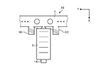
- FIG. 1 Top view of the lead frame for the winding inductor according to the first embodiment
- FIG. The figure which shows the state which the package covering the winding part was formed in Embodiment 1.
- FIG. The figure which shows the state which the winding inductor which concerns on Embodiment 1 are separated from the lead frame for a winding inductor.
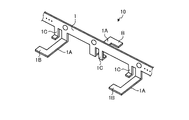
- FIG. 1 is a plan view of a lead frame for a winding inductor according to a first embodiment.
- the lead frame 10 for a winding inductor includes a core portion 1A, a connecting portion 1, a first terminal portion 1C, and a second terminal portion 1B.
- the lead frame 10 for a winding inductor is formed of, for example, a metal plate material.
- the lead frame 10 for the winding inductor is provided with a plurality of core portions 1A.
- the plurality of core portions 1A extend in the positive direction along the X axis, which is the first direction, and are provided side by side in the direction along the Y axis perpendicular to the X axis.
- the direction along the Y axis is the second direction.
- the lead frame 10 for a winding inductor is provided with a connecting portion 1 for connecting one ends 1Aa of a plurality of core portions 1A.
- the width of the connecting portion with the connecting portion 1 is narrower than the width of the other portions.
- the lead frame 10 for the winding inductor is provided with a first terminal portion 1C.
- the first terminal portion 1C extends from the connecting portion 1 in the positive direction along the X axis. This can be rephrased that the first terminal portion 1C is connected to the core portion 1A via the connecting portion 1.
- the first terminal portion 1C is provided on the positive direction side, which is one side along the Y axis with respect to the core portion 1A.
- the tip of the first terminal portion 1C is bent in the positive direction along the Y axis.
- the bent end portion of the first terminal portion 1C becomes the exposed portion 1Ca.
- the bent portion of the first terminal portion 1C serves as a tangled portion for entwining the winding described later, and the exposed portion 1Ca serves as a mounting portion.
- the lead frame 10 for the winding inductor is provided with a second terminal portion 1B.
- the second terminal portion 1B is formed so as to extend from the other end 1Ab of the core portion 1A in the positive direction along the Y axis. This can be rephrased as the second terminal portion 1B being directly connected to the core portion 1A.
- the second terminal portion 1B is provided with a step portion 1Bb.
- the region on the positive direction side along the Y axis with respect to the step portion 1Bb is a region having a narrower width along the X axis than the other regions, and this region is It becomes the exposed part 1Ba.
- the length of the first terminal portion 1C along the X axis is shorter than the length of the core portion 1A along the X axis.
- the stepped portion 1Bb serves as a tangled portion for entwining the winding described later, and the exposed portion 1Ba serves as a mounting portion.
- the distance a between adjacent cores 1A is wider than the width b of the cores 1A along the Y axis. Further, the distance c between the second terminal portion 1B and the core portion 1A adjacent to the positive direction side along the Y axis with respect to the core portion 1A provided with the second terminal portion 1B is the core portion 1A. Wider than the width along the Y-axis of.
- FIG. 2 is a diagram illustrating a step of forming a winding portion on the core portion in the first embodiment.
- a winding machine 2 is used to wind the winding around the core portion 1A to form the winding portion 3.
- the winding portion 3 is a coil.
- the ends of the windings are entwined and joined to the first terminal portion 1C and the second terminal portion 1B.
- the portion joined to the first terminal portion 1C and the second terminal portion 1B is shown as the joint portion 1D.
- the end portion of the winding is joined to the first terminal portion 1C and the second terminal portion 1B by brazing or the like.
- a winding is entwined around the first terminal portion 1C together with the core portion 1A. Since a coating is formed on the winding, the winding and the core portion 1A are not electrically connected.
- the winding and the first terminal portion 1C are electrically connected by joining by brazing or the like, and the winding and the second terminal portion 1B are electrically connected.
- the windings of the first terminal portion 1C and the core portion 1A are entwined together, it is possible to prevent a short circuit between the first terminal portion 1C and the second terminal portion 1B through the core portion 1A. can. If the winding cannot be entwined together with the first terminal portion 1C and the core portion 1A, the winding is passed through the gap between the first terminal portion 1C and the core portion 1A and the first terminal portion 1C is passed. It is necessary to entangle the winding only in the nozzle 2a, which increases the restriction on the shape of the nozzle 2a.
- the winding is wound in a relatively generous path without passing through the gap between the first terminal portion 1C and the core portion 1A. Since the wire can be passed through, it is possible to reduce the restriction on the shape of the nozzle 2a.
- the core portion 1A is provided in a comb-teeth shape with respect to the connecting portion 1. Therefore, the winding machine 2 can be inserted from the other end 1Ab side of the core portion 1A where the connecting portion 1 is not provided to form the winding portion 3. Further, since the winding machine 2 can form the winding portion 3 if it has an operating mechanism of only one axis, that is, an operating mechanism along the X axis, it is possible to improve productivity and reduce equipment cost. ..
- FIG. 3 is a diagram showing a state in which a winding portion is formed in the core portion in the first embodiment.
- FIG. 4 is a diagram showing a state in which a package covering the winding portion is formed in the first embodiment.
- the winding portion 3 is formed on the plurality of core portions 1A.
- the lead frame 10 for the winding inductor is along the Y axis, that is, along the extending direction of the connecting portion 1 with respect to the winding machine 2. Will be moved.
- the package 4 that covers the first terminal portion 1C, the second terminal portion 1B, and the winding portion 3 is formed.
- the package 4 is formed of, for example, an insulating resin. Of the first terminal portion 1C and the second terminal portion 1B, the exposed portions 1Ba and 1Ca are exposed without being covered by the package 4.
- FIG. 5 is a diagram showing a state in which the winding inductor according to the first embodiment is separated from the lead frame for the winding inductor. Next, as shown in FIG. 5, the winding inductor 11 is formed by cutting the connecting portion 1 by press working or the like.
- both the first terminal portion 1C and the second terminal portion 1B are connected by one connecting portion 1. Therefore, in order to connect the second terminal portion 1B, it is not necessary to provide another connecting portion so as to face the connecting portion 1.
- the other connecting portion is deleted. No other connecting part is formed. Therefore, the man-hours can be reduced in the manufacturing process of the winding inductor 11. Further, in the manufacturing process of the lead frame 10 for the winding inductor, the material efficiency of one plate material as a base material can be improved.
- the distance c is wider than the width b. Therefore, as shown in FIG. 1, the connecting portion, the core portion, the first terminal, and the second terminal are used.
- the core part 1A of the other part is inserted between the core parts 1A of one part. It is possible to take a configuration that has been set. That is, when the above-mentioned two parts are obtained by punching one plate material, the portion to be cut can be reduced. That is, in the manufacturing process of the lead frame 10 for the winding inductor, the material efficiency of one plate material as a base material can be further improved.
- the winding locus at the time of entanglement is simplified and the surface surface is simplified by forming the entanglement portion and the mounting portion into a shape suitable for each function. It is possible to support a wide range of mounting methods such as mounting and through-hole mounting.
- the winding inductor 11 can be miniaturized in the radial direction of the winding portion 3.
- FIG. 6 is a diagram showing a modified example of the first terminal portion and the second terminal portion in the first embodiment.
- the first terminal portion 1C and the second terminal portion 1B according to the modified example are formed in a rectangular shape that also serves as a burr portion and a mounting portion. Since the shapes of the first terminal portion 1C and the second terminal portion 1B are simplified, it is possible to reduce the warp of the lead frame 10 for the winding inductor and reduce the processing cost.
- FIG. 7 is a diagram showing another modification of the first terminal portion and the second terminal portion in the first embodiment.
- the first terminal portion 1C and the second terminal portion 1B according to the other modification are formed symmetrically in the direction along the Y axis with the core portion 1A as the center.
- the center of rotation of the winding machine 2 is the entanglement of the winding around the first terminal portion 1C and the second terminal portion 1B, and when the winding is wound around the core portion 1A. Since they are the same, the control of the winding machine 2 can be simplified.
- FIG. 8 is a diagram showing a modified example of the lead frame for the winding inductor according to the first embodiment.
- the angle ⁇ formed by the extending direction of the connecting portion 1 and the extending direction of the core portion 1A is an acute angle.
- the lead frame 10 for the winding inductor is moved in the extending direction of the connecting portion 1 to wind the winding from the second terminal portion 1B to the first terminal portion 1C, the winding ends. Since the distance between the terminal portion 1C of 1 and the second terminal portion 1B, which is the start of winding the winding around the next core portion 1A, becomes short, the winding machine 2 moves when forming the winding portion 3. The amount can be reduced to improve work efficiency.
- FIG. 9 is a cross-sectional view taken along the line AA shown in FIG. 2 and is a diagram for explaining the cross-sectional shape of the core portion.
- FIG. 10 is a cross-sectional view taken along the line AA shown in FIG. 2 and is a diagram for explaining a modified example of the cross-sectional shape of the core portion.
- FIG. 11 is a cross-sectional view taken along the line AA shown in FIG. 2 and is a diagram for explaining another modification of the cross-sectional shape of the core portion.
- the cross-sectional shape of the core portion 1A may be a flat plate shape. This makes it possible to simplify the shape of the lead frame 10 for the winding inductor and reduce the manufacturing man-hours. Further, as shown in FIG. 10, the cross-sectional shape of the core portion 1A may be L-shaped. As a result, the bending strength of the core portion 1A is improved, and the winding can be wound with a higher tension. Therefore, it becomes possible to use a winding having a large diameter that requires higher tension. Further, as shown in FIG. 11, the magnetic core 6 may be provided on the core portion 1A. The magnetic core 6 is joined or adhered to the core portion 1A.
- the bending strength of the portion where the winding portion 3 including the core portion 1A is formed is improved, and the winding can be wound with a higher tension. Therefore, it becomes possible to use a winding having a large diameter that requires higher tension. Further, by providing the magnetic core 6, the inductance of the winding inductor 11 can be improved.
- FIG. 12 is a diagram showing still another modification of the first terminal portion and the second terminal portion in the first embodiment.
- a first wall is raised along the direction along the X axis and the direction perpendicular to the direction along the Y axis.
- 1 Cc is provided.
- a second wall 1Bc raised in the same direction as the first wall 1Cc is provided at one end of the second terminal portion 1B on the one end 1Aa side of the core portion 1A. Further, the first wall 1Cc and the second wall 1Bc face each other.
- the winding portion 3 formed between the first wall 1Cc and the second wall 1Bc is guided by the first wall 1Cc and the second wall 1Bc.
- the shape is stable. Therefore, it is not necessary to complicate the configuration of the winding machine 2 in order to stabilize the shape of the winding portion 3.
- FIG. 13 is a diagram showing still another modification of the first terminal portion and the second terminal portion in the first embodiment.
- the second terminal portion 1B may be formed on the side opposite to the side where the first terminal portion 1C is provided with respect to the core portion 1A.
- the second terminal portion 1B is formed directly on the connecting portion 1.
- the length of the winding inductor 11 along the radial direction of the winding portion 3, that is, the length along the Y axis is the length along the axial direction of the winding portion 3, that is, the X axis. It will be shorter than the length along it.
- at least two terminal portions can be positioned on one side surface along the Y axis. As a result, the mounting area can be reduced by making the direction along the X-axis perpendicular to the mounting surface of the substrate.
- FIG. 14 is a diagram showing another modification of the lead frame for the winding inductor according to the first embodiment.
- the core portions 1A are alternately bent in the opposite directions by 90 °, and the adjacent core portions 1A extend in different directions.
- the distance between the core portions 1A extending in the same direction becomes twice the distance between the core portions 1A extending in the same direction before bending. Therefore, the nozzle 2a of the winding machine 2 and the core portion 1A or the already formed winding portion 3 are less likely to interfere with each other.
- restrictions on the shape of the nozzle 2a of the winding machine 2 are relaxed, and a larger winding portion can be formed.
- the first terminal portion 1C is also alternately bent in the opposite direction by 90 °. Further, if the adjacent core portions 1A extend in different directions, the distance between the core portions 1A can be widened, so that the angle at which the core portions 1A are bent is not limited to 90 °.
- FIG. 15 is a diagram showing still another modification of the lead frame for the winding inductor according to the first embodiment.
- a core portion 1A bent 90 ° toward the front of the paper surface, a core portion 1A not bent, and a core portion 1A bent 90 ° toward the back of the paper surface are provided in this order.
- the distance between the core portions 1A extending in the same direction becomes three times the distance between the core portions 1A extending in the same direction before bending. Therefore, the nozzle 2a of the winding machine 2 and the core portion 1A or the already formed winding portion 3 are less likely to interfere with each other.
- the first terminal portion 1C is also bent 90 ° in the front direction of the paper surface, the first terminal portion 1C not bent, and 90 ° in the back direction of the paper surface.
- the first terminal portions 1C provided are provided in order. Further, if the adjacent core portions 1A extend in different directions, the distance between the core portions 1A can be widened, so that the angle at which the core portions 1A are bent is not limited to 90 °.
- FIG. 16 is a diagram showing a state in which a winding portion is formed in a core portion in the process of manufacturing a power generation element using the lead frame for a winding inductor according to the first embodiment.
- the power generation element is manufactured by using the lead frame 10 for the winding inductor according to the first embodiment, even if the magnetic wire material 12 having a large Barkhausen effect is arranged in the vicinity of the winding portion 3 which is a coil. good.
- the magnetic wire rod 12 is arranged on the core portion 1A, and then the winding is wound to form the winding portion 3.
- the magnetic wire rod 12 By placing it in the vicinity of the winding portion 3, the magnetic wire rod 12 is magnetized and inverted by the large Barkhausen effect in response to a change in the external magnetic field.
- the lead frame 10 for a winding inductor can be used as a winding core in which an electromotive force is generated in the winding portion 3 due to magnetization reversal and a change in an external magnetic field can be detected by a voltage. This makes it possible to obtain a power generation element having high material efficiency.
- the position of the magnetic wire 12 is not limited to the example of being arranged inside the winding portion 3 together with the core portion 1A, and may be adhered to the outside of the winding portion 3, for example.
- the magnetic wire rod 12 may be fixed to the core portion 1A by adhesion or the like and then wound, or after the winding portion 3 is formed, the magnetic wire rod 12 is inserted inside the winding portion 3 or fixed in the vicinity. You may.
- FIG. 17 is a diagram showing a configuration of an encoder according to the second embodiment.
- the encoder 100 according to the second embodiment includes a rotation detection element 40 and a rotation detection board 30.
- the rotation detecting element 40 includes a power generation element 13 using a lead frame 10 for a winding inductor and a rotating disk 20.
- the turntable 20 has a magnetic pole including a pair or more of S poles and N poles, and is rotatably supported.
- the rotating disk 20 may be a magnetized magnetic material, or may be a non-magnetic disk in which a plurality of magnets are installed.
- the power generation element 13 and the turntable 20 are provided so as to face each other.
- An electromotive force is generated in the power generation element 13 due to a change in the magnetic field due to the rotation of the turntable 20, a current flows through the rotation detection substrate 30, and rotation is detected.
- the orientation of the power generation element 13 is not limited to the example shown in FIG.
- the power generation element 13 shown in FIG. 17 is manufactured by using the lead frame 10 for a winding inductor shown in FIGS. 1 and 2.
- the configuration shown in the above embodiments is an example of the contents of the present disclosure.
- the configurations of the embodiments can be combined with other known techniques. It is possible to omit or change a part of the configuration of the embodiment without departing from the gist of the present disclosure.
Landscapes
- Engineering & Computer Science (AREA)
- Power Engineering (AREA)
- Manufacturing & Machinery (AREA)
- Coils Or Transformers For Communication (AREA)
- Transmission And Conversion Of Sensor Element Output (AREA)
- Coil Winding Methods And Apparatuses (AREA)
- Manufacturing Cores, Coils, And Magnets (AREA)
Priority Applications (1)
| Application Number | Priority Date | Filing Date | Title |
|---|---|---|---|
| JP2022575526A JP7511679B2 (ja) | 2021-01-15 | 2021-12-28 | 巻線インダクタ用リードフレーム、巻線インダクタの製造方法、発電素子、回転検出素子、およびエンコーダ |
Applications Claiming Priority (2)
| Application Number | Priority Date | Filing Date | Title |
|---|---|---|---|
| JP2021-004729 | 2021-01-15 | ||
| JP2021004729 | 2021-01-15 |
Publications (1)
| Publication Number | Publication Date |
|---|---|
| WO2022153879A1 true WO2022153879A1 (ja) | 2022-07-21 |
Family
ID=82447321
Family Applications (1)
| Application Number | Title | Priority Date | Filing Date |
|---|---|---|---|
| PCT/JP2021/048985 Ceased WO2022153879A1 (ja) | 2021-01-15 | 2021-12-28 | 巻線インダクタ用リードフレーム、巻線インダクタの製造方法、発電素子、回転検出素子、およびエンコーダ |
Country Status (2)
| Country | Link |
|---|---|
| JP (1) | JP7511679B2 (https=) |
| WO (1) | WO2022153879A1 (https=) |
Citations (5)
| Publication number | Priority date | Publication date | Assignee | Title |
|---|---|---|---|---|
| JPS63313906A (ja) * | 1987-01-14 | 1988-12-22 | Takeshi Ikeda | 箔巻電子部品およびその製造方法 |
| JPH04147009A (ja) * | 1990-10-09 | 1992-05-20 | Matsushita Electric Ind Co Ltd | 多回転式絶対値ロータリーエンコーダ |
| JPH0669036A (ja) * | 1992-08-13 | 1994-03-11 | Tokin Corp | 巻線チップインダクタ及びその製造方法 |
| JPH06188459A (ja) * | 1992-12-17 | 1994-07-08 | Toshiba Corp | 半導体発光装置とその製造方法 |
| JPH06215943A (ja) * | 1993-01-19 | 1994-08-05 | Tokin Corp | チップインダクタ及びその製造方法並びにチップインダクタに用いるリードフレーム |
Family Cites Families (2)
| Publication number | Priority date | Publication date | Assignee | Title |
|---|---|---|---|---|
| JP2001085259A (ja) | 1999-09-09 | 2001-03-30 | Citizen Electronics Co Ltd | コイルとその製造方法 |
| JP3947522B2 (ja) | 2004-02-10 | 2007-07-25 | Tdk株式会社 | 面実装型コイル部品およびその製造方法 |
-
2021
- 2021-12-28 WO PCT/JP2021/048985 patent/WO2022153879A1/ja not_active Ceased
- 2021-12-28 JP JP2022575526A patent/JP7511679B2/ja active Active
Patent Citations (5)
| Publication number | Priority date | Publication date | Assignee | Title |
|---|---|---|---|---|
| JPS63313906A (ja) * | 1987-01-14 | 1988-12-22 | Takeshi Ikeda | 箔巻電子部品およびその製造方法 |
| JPH04147009A (ja) * | 1990-10-09 | 1992-05-20 | Matsushita Electric Ind Co Ltd | 多回転式絶対値ロータリーエンコーダ |
| JPH0669036A (ja) * | 1992-08-13 | 1994-03-11 | Tokin Corp | 巻線チップインダクタ及びその製造方法 |
| JPH06188459A (ja) * | 1992-12-17 | 1994-07-08 | Toshiba Corp | 半導体発光装置とその製造方法 |
| JPH06215943A (ja) * | 1993-01-19 | 1994-08-05 | Tokin Corp | チップインダクタ及びその製造方法並びにチップインダクタに用いるリードフレーム |
Also Published As
| Publication number | Publication date |
|---|---|
| JP7511679B2 (ja) | 2024-07-05 |
| JPWO2022153879A1 (https=) | 2022-07-21 |
Similar Documents
| Publication | Publication Date | Title |
|---|---|---|
| KR100301480B1 (ko) | 리니어 모터용 고정자 코어 및 이를 이용한 고정자 제조방법 | |
| JP3745884B2 (ja) | モータ構造及びその製造方法 | |
| JP3561251B2 (ja) | 往復動式モータの固定子の構造 | |
| JP6541677B2 (ja) | アンテナ及びアンテナ製造方法 | |
| JP7109713B1 (ja) | 発電素子、磁気センサ、エンコーダおよびモータ | |
| JP3309372B2 (ja) | コイル装置及びその製造方法 | |
| US20040021375A1 (en) | Stepping motor and manufacturing method therefor | |
| US6861773B2 (en) | Stepping motor | |
| JP2004207396A (ja) | 面実装型コイル部品 | |
| JP4062723B2 (ja) | 回転形モータおよびその製造方法 | |
| WO2022153879A1 (ja) | 巻線インダクタ用リードフレーム、巻線インダクタの製造方法、発電素子、回転検出素子、およびエンコーダ | |
| US11253947B2 (en) | Magnet wire bonding method and bonding structure | |
| JP2007014088A (ja) | 回転電機のステータ、回転電機、及び回転電機のステータの製造方法 | |
| JPH0373224B2 (https=) | ||
| WO2008018166A1 (en) | Motor | |
| CN110932421B (zh) | 三相永磁同步电机及具有其的吸尘器 | |
| JPH0619296Y2 (ja) | リニアアクチュエ−タ用プリントコイル | |
| JPS59162737A (ja) | モ−タコイル | |
| JP2005110398A (ja) | 基板のない空芯高密度電機子とこれを用いた回転機 | |
| JP3647133B2 (ja) | インダクタンス素子 | |
| JP3713422B2 (ja) | パルス信号発生装置並びにパルス信号発生装置に使用するコイル巻きボビンおよびその製造方法 | |
| JPS6225858A (ja) | 面対向型ブラシレスモ−タ | |
| JPS5915253Y2 (ja) | リニアモ−タ | |
| KR100273416B1 (ko) | 리니어 모터의 고정자구조 | |
| JPH0223057A (ja) | リニアモータのコイル製造方法 |
Legal Events
| Date | Code | Title | Description |
|---|---|---|---|
| 121 | Ep: the epo has been informed by wipo that ep was designated in this application |
Ref document number: 21919763 Country of ref document: EP Kind code of ref document: A1 |
|
| ENP | Entry into the national phase |
Ref document number: 2022575526 Country of ref document: JP Kind code of ref document: A |
|
| NENP | Non-entry into the national phase |
Ref country code: DE |
|
| 122 | Ep: pct application non-entry in european phase |
Ref document number: 21919763 Country of ref document: EP Kind code of ref document: A1 |