WO2022153517A1 - 回転電機 - Google Patents
回転電機 Download PDFInfo
- Publication number
- WO2022153517A1 WO2022153517A1 PCT/JP2021/001392 JP2021001392W WO2022153517A1 WO 2022153517 A1 WO2022153517 A1 WO 2022153517A1 JP 2021001392 W JP2021001392 W JP 2021001392W WO 2022153517 A1 WO2022153517 A1 WO 2022153517A1
- Authority
- WO
- WIPO (PCT)
- Prior art keywords
- electric machine
- rotary electric
- rotor
- permanent magnets
- field
- Prior art date
- Legal status (The legal status is an assumption and is not a legal conclusion. Google has not performed a legal analysis and makes no representation as to the accuracy of the status listed.)
- Ceased
Links
Images









Classifications
-
- H—ELECTRICITY
- H02—GENERATION; CONVERSION OR DISTRIBUTION OF ELECTRIC POWER
- H02K—DYNAMO-ELECTRIC MACHINES
- H02K1/00—Details of the magnetic circuit
- H02K1/06—Details of the magnetic circuit characterised by the shape, form or construction
- H02K1/22—Rotating parts of the magnetic circuit
- H02K1/27—Rotor cores with permanent magnets
- H02K1/2786—Outer rotors
- H02K1/2787—Outer rotors the magnetisation axis of the magnets being perpendicular to the rotor axis
- H02K1/2789—Outer rotors the magnetisation axis of the magnets being perpendicular to the rotor axis the rotor consisting of two or more circumferentially positioned magnets
- H02K1/279—Magnets embedded in the magnetic core
-
- H—ELECTRICITY
- H02—GENERATION; CONVERSION OR DISTRIBUTION OF ELECTRIC POWER
- H02K—DYNAMO-ELECTRIC MACHINES
- H02K21/00—Synchronous motors having permanent magnets; Synchronous generators having permanent magnets
- H02K21/12—Synchronous motors having permanent magnets; Synchronous generators having permanent magnets with stationary armatures and rotating magnets
- H02K21/14—Synchronous motors having permanent magnets; Synchronous generators having permanent magnets with stationary armatures and rotating magnets with magnets rotating within the armatures
- H02K21/16—Synchronous motors having permanent magnets; Synchronous generators having permanent magnets with stationary armatures and rotating magnets with magnets rotating within the armatures having annular armature cores with salient poles
-
- H—ELECTRICITY
- H02—GENERATION; CONVERSION OR DISTRIBUTION OF ELECTRIC POWER
- H02K—DYNAMO-ELECTRIC MACHINES
- H02K1/00—Details of the magnetic circuit
- H02K1/06—Details of the magnetic circuit characterised by the shape, form or construction
- H02K1/12—Stationary parts of the magnetic circuit
- H02K1/16—Stator cores with slots for windings
-
- H—ELECTRICITY
- H02—GENERATION; CONVERSION OR DISTRIBUTION OF ELECTRIC POWER
- H02K—DYNAMO-ELECTRIC MACHINES
- H02K1/00—Details of the magnetic circuit
- H02K1/06—Details of the magnetic circuit characterised by the shape, form or construction
- H02K1/22—Rotating parts of the magnetic circuit
- H02K1/27—Rotor cores with permanent magnets
- H02K1/2786—Outer rotors
- H02K1/2787—Outer rotors the magnetisation axis of the magnets being perpendicular to the rotor axis
- H02K1/2789—Outer rotors the magnetisation axis of the magnets being perpendicular to the rotor axis the rotor consisting of two or more circumferentially positioned magnets
- H02K1/2791—Surface mounted magnets; Inset magnets
-
- H—ELECTRICITY
- H02—GENERATION; CONVERSION OR DISTRIBUTION OF ELECTRIC POWER
- H02K—DYNAMO-ELECTRIC MACHINES
- H02K21/00—Synchronous motors having permanent magnets; Synchronous generators having permanent magnets
- H02K21/12—Synchronous motors having permanent magnets; Synchronous generators having permanent magnets with stationary armatures and rotating magnets
- H02K21/22—Synchronous motors having permanent magnets; Synchronous generators having permanent magnets with stationary armatures and rotating magnets with magnets rotating around the armatures, e.g. flywheel magnetos
- H02K21/227—Synchronous motors having permanent magnets; Synchronous generators having permanent magnets with stationary armatures and rotating magnets with magnets rotating around the armatures, e.g. flywheel magnetos having an annular armature coil
-
- H—ELECTRICITY
- H02—GENERATION; CONVERSION OR DISTRIBUTION OF ELECTRIC POWER
- H02K—DYNAMO-ELECTRIC MACHINES
- H02K2213/00—Specific aspects, not otherwise provided for and not covered by codes H02K2201/00 - H02K2211/00
- H02K2213/03—Machines characterised by numerical values, ranges, mathematical expressions or similar information
-
- H—ELECTRICITY
- H02—GENERATION; CONVERSION OR DISTRIBUTION OF ELECTRIC POWER
- H02K—DYNAMO-ELECTRIC MACHINES
- H02K29/00—Motors or generators having non-mechanical commutating devices, e.g. discharge tubes or semiconductor devices
- H02K29/03—Motors or generators having non-mechanical commutating devices, e.g. discharge tubes or semiconductor devices with a magnetic circuit specially adapted for avoiding torque ripples or self-starting problems
Definitions
- the disclosed technique relates to a variable field motor which is a rotary electric machine and has a DC field winding in a stator.
- Permanent magnet type rotary electric machines are often used for drive motors such as EVs.
- automobile motors require a wide operating range. Specifically, it is necessary to strengthen the field of the magnet in order to output high torque at low rotation, and to weaken the field of magnet in order to relax the voltage saturation at high rotation.
- a variable field motor has been developed that can realize a wide operating range by appropriately adjusting the field amount according to the operating point in which the magnet and the field coil are operated in combination.
- the disclosed technique was made in view of the above problems, and an object of the present disclosure technique is to provide a rotating electric machine that does not generate unbalanced magnetic attraction in principle.
- the rotary electric machine is a rotary electric machine including a stator and a rotor, and the rotor includes a plurality of permanent magnets arranged in the circumferential direction of the rotation axis and a plurality of convex portions arranged in the circumferential direction.
- the stator has a plurality of teeth, an armature winding wound around the plurality of teeth, and a field winding wound around the plurality of teeth.
- a field magnetic pole is formed in the plurality of convex portions by energizing the field winding and the plurality of permanent magnets, and the plurality of permanent magnets and the plurality of teeth are alternately arranged at intervals in the circumferential direction.
- the field magnetic poles are formed, and all of the plurality of permanent magnets have the same polarity.
- the number of poles Pr of the field magnetic pole composed of the magnet and the plurality of convex portions is
- the rotating electric machine according to the present disclosure technology is a magnetic flux modulation hybrid field motor having a field source in the stator, and has an effect of suppressing eccentricity and vibration of the rotating shaft caused by an unbalanced magnetic attraction.
- FIG. 1 is a configuration diagram showing a configuration of a magnetic flux modulation hybrid field motor which is an example of a rotary electric machine according to the first embodiment.
- FIG. 2 is a cross-sectional view 1 of the rotary electric machine according to the first embodiment.
- FIG. 3 is a cross-sectional view No. 2 of the rotary electric machine according to the first embodiment.
- FIG. 4 is a schematic diagram showing an outline of the wiring of the rotary electric machine according to the first embodiment.
- FIG. 5 is a magnetic flux diagram No. 1 by a permanent magnet in the electric angle No. 1 of the rotary electric machine according to the first embodiment.
- FIG. 6 is a magnetic flux diagram No. 2 by a permanent magnet in the electric angle No. 2 of the rotary electric machine according to the first embodiment.
- FIG. 1 is a configuration diagram showing a configuration of a magnetic flux modulation hybrid field motor which is an example of a rotary electric machine according to the first embodiment.
- FIG. 2 is a cross-sectional view 1 of the
- FIG. 7 is a magnetic flux diagram No. 1 when the field winding F (from F1 to F6) in the electric angle 1 of the rotary electric machine according to the first embodiment is energized.
- FIG. 8 is a magnetic flux diagram No. 2 when the field winding F (from F1 to F6) in the electric angle 2 of the rotary electric machine according to the first embodiment is energized.
- FIG. 9 is a magnetic flux diagram No. 1 when the armature winding of the rotary electric machine according to the first embodiment is energized.
- FIG. 10 is a magnetic flux diagram No. 2 when the armature winding of the rotary electric machine according to the first embodiment is energized.
- FIG. 11 is a schematic view No.
- FIG. 12 is a schematic view No. 2 showing an electromagnetic force acting on the rotor of the rotary electric machine according to the first embodiment.
- FIG. 13 is a magnetic flux diagram when a current is applied to the field winding when the number of consecutive poles of the rotary electric machine according to the first embodiment is 7.
- FIG. 14 is a magnetic flux diagram when a current is applied to the armature winding when the number of consecutive poles of the rotary electric machine according to the first embodiment is 7.
- FIG. 15 is a development schematic diagram of a stator teeth when the number of poles of the sequential pole is 5, the number of pole pairs of the armature winding of the stator is 2, and the number of pole pairs of the DC field winding is 3.
- FIG. 16 is a development schematic diagram of a stator teeth when the number of poles of the sequential pole is 11, the number of pole pairs of the armature winding of the stator is 5, and the number of pole pairs of the DC field winding is 6.
- FIG. 17 is a development schematic diagram of a stator teeth when the number of poles of the sequential pole is 6, the number of pole pairs of the armature winding of the stator is 1, and the number of pole pairs of the DC field winding is 7.
- FIG. 18 is a cross-sectional view of the rotary electric machine according to the second embodiment.
- FIG. 19 is a cross-sectional view of the rotary electric machine according to the third embodiment.
- FIG. 20 is a cross-sectional view of the rotary electric machine according to the fourth embodiment.
- FIG. 21 is a bird's-eye view of the entire rotary electric machine according to the fifth embodiment.
- FIG. 22 is a bird's-eye view of the rotor according to the fifth embodiment.
- FIG. 1 is a configuration diagram showing a configuration of a magnetic flux modulation hybrid field motor which is an example of the rotary electric machine 100 according to the first embodiment.
- the rotary electric machine 100 according to the first embodiment includes a stator 1 formed in an annular shape and a rotor 2 provided so as to face the stator 1.
- the rotor 2 is provided inside the stator 1 in the radial direction.
- the radial direction of the rotor 2 is simply referred to as “diametrical direction”
- the circumferential direction of the rotor 2 is simply referred to as “circumferential direction”
- the axial direction of the rotation axis of the rotor 2 is simply referred to as “diameter direction”. Called “axial”.
- the rotor 2 includes a rotor core 3 and a plurality of permanent magnets 4 attached to the outer peripheral surface of the rotor core 3.
- the rotor core 3 is press-fitted with a shaft 5 extending in the direction of the rotation axis.
- the shaft 5 is connected to the stator bracket 9 via one or more bearings 6.
- the stator 1 includes a stator core 7, a plurality of coils 8 provided on the stator core 7, and the stator bracket 9.
- the stator core 7 is connected to the stator bracket 9 that covers the entire permanent magnet type synchronous motor by a method such as press fitting or adhesion. Further, the stator bracket 9 is in contact with the cover 10 and plays a role of preventing the rotor 2 from scattering, fixing the permanent magnet type synchronous motor, and cooling the heat generated by the stator 1.
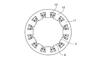
- FIG. 2 is a cross-sectional view 1 of the rotary electric machine 100 according to the first embodiment.
- FIG. 2 shows a shape related to the electromagnetic function of the stator 1 of the rotary electric machine 100.
- the stator core 7 has a core back 11 formed in an annular shape and a plurality of teeth 12 protruding inward in the radial direction from the core back 11.
- the plurality of teeth 12 are arranged at equal intervals in the circumferential direction.
- a plurality of slots 13 are formed between the plurality of teeth 12 adjacent to each other in the circumferential direction.
- the coil 8 is stored in the plurality of slots 13.
- the plurality of permanent magnets 4 are arranged in the circumferential direction on the radial outer side of the rotor core 3 and are connected to the rotor core 3.
- FIG. 3 is a cross-sectional view 2 of the rotary electric machine 100 according to the first embodiment.
- FIG. 3 shows a shape related to the electromagnetic function of the rotor 2 of the rotary electric machine 100.
- the rotor 2 has a rotor core 3 and a permanent magnet 4 attached to the surface of the rotor core 3. Further, the rotor core 3 has convex portions 16 formed alternately between the permanent magnets 4.
- the shape of the convex portion 16 shown in FIG. 3 is generally rectangular, but may be arcuate. Further, the curvature of the curve in which the convex portion 16 and the void are in contact with each other may be different from the outermost outer diameter of the rotor 2. Further, the tip portion of the convex portion 16 may be formed on the fillet by an arc having a different curvature. The shape of these convex portions 16 is designed to adjust the harmonics of the magnetic flux formed by the field winding F to a desired value.
- the permanent magnet 4 may have corners formed on the fillet. By forming the corners on the fillet, it can be expected to reduce the eddy current loss generated at the tip of the permanent magnet 4. Further, the curvature of the outer peripheral shape of the permanent magnet 4 may be different from the outermost outer diameter of the rotor 2.
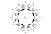
- FIG. 4 is a schematic diagram showing an outline of the connection of the rotary electric machine 100 according to the first embodiment.
- FIG. 4 shows that the A phase, the B phase, and the C phase of the armature winding are three-phase AC windings each having a phase difference of 120 degrees.
- the field winding F shown in FIG. 4 is a DC field winding.
- each phase of the armature winding is wound in the same direction, and the magnetic flux generated by the armature constitutes a consequent pole.
- the armature magnetic flux due to the ABC phase of the armature winding is interlinked with the rotor core 3 via the teeth 12 on which the field winding F is wound, and the ABC phase of the armature winding is wound again.
- the pole is formed in the gap by returning to the tooth 12 to be wire.
- the winding directions of the field windings F are all the same.
- the field magnetic flux generated by the field winding F is interlinked with the rotor core 3 via the teeth 12 on which the armature winding ABC phase is wound, and the field winding F is wound again. By returning to the teeth 12, a field pole can be formed.
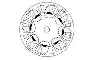
- FIG. 5 is a magnetic flux diagram No. 1 by the permanent magnet 4 at the electric angle No. 1 of the rotary electric machine 100 according to the first embodiment.
- the polarities of the permanent magnets 4 illustrated in FIG. 5 are all the same, and here, they are all N poles.
- the magnetic flux generated from the permanent magnet 4 passes through the core back 11 via the teeth 12 of the stator 1 and returns to the permanent magnet 4 through the convex portions 16 arranged between the permanent magnets 4. That is, each convex portion 16 plays a role like an S pole in the permanent magnet 4.
- FIG. 6 is a magnetic flux diagram 2 of the permanent magnet 4 at the electric angle 2 of the rotary electric machine 100 according to the first embodiment. 5 and 6 show poles modulated in the field poles formed on the plurality of convex portions 16 by the energization of the armature winding and the field winding and the plurality of permanent magnets 4. The ratio of the number to the number of slots with armature windings is 2: 3.
- FIG. 7 is a magnetic flux diagram No. 1 when the field winding F (from F1 to F6) in the electric angle 1 of the rotary electric machine 100 according to the first embodiment is energized. As shown in FIG. 7, since the winding directions of the field windings F are all the same, a 12-pole field magnetic flux is generated.
- FIG. 8 is a magnetic flux diagram No.
- Pr represents the number of poles of the field magnetic pole composed of the permanent magnet 4 and the convex portion 16.
- FIG. 11 is a schematic view No. 1 showing an electromagnetic force acting on the rotor 2 of the rotary electric machine 100 according to the first embodiment.
- FIG. 12 is a schematic view 2 showing an electromagnetic force acting on the rotor 2 of the rotary electric machine 100 according to the first embodiment.
- FIG. 13 is a magnetic flux diagram when a current is applied to the field winding F when Pr of the rotary electric machine 100 according to the first embodiment is 7. As can be seen by comparison with FIG. 7, FIG. 13 shows that the magnetic flux lines are asymmetric with respect to the rotation axis. In FIG. 13,
- 1, which is because a magnetic flux of the first order in space is generated.
- FIG. 13 shows that
- FIG. 17 is an exploded schematic view of the teeth 12 of the stator 1 when Pr is 7, P a is 1, and P f is 6.
- FIG. 14 is a magnetic flux diagram when a current is applied to the armature winding when Pr of the rotary electric machine 100 according to the first embodiment is 7. As can be seen by comparison with FIG. 9, FIG. 14 shows that the magnetic flux lines are asymmetric with respect to the axis of rotation. In FIG. 14,
- 1, which is because a magnetic flux of the first order in space is generated.
- FIG. 14 shows that
- FIG. 15 is a development schematic view of the teeth 12 of the stator 1 when Pr is 5, P a is 2, and P f is 3.
- a phase, B phase, and C phase are arranged to form four poles.
- the field winding F is arranged between each armature winding to form 6 poles.
- the absolute value of the difference between the pole pairs of the armature and the field winding F is 1, that is,
- 1, a magnetic flux of the first degree in space is generated.
- the first-order magnetic flux in space produces an unbalanced magnetic attraction.
- ⁇ 1. This means that even when P a + P f Pr is established, for example, P a is 4, P f is 3, P r is 7, and
- 1. , Spatial first-order magnetic flux is generated and unbalanced magnetic attraction is generated.
- FIG. 16 is a development schematic view of the teeth 12 of the stator 1 when Pr is 11, P a is 5, and P f is 6.
- a phase, B phase, and C phase are arranged on each tooth 12 to form 10 poles.
- the field winding F is also wound around each tooth 12 to form 12 poles.
- 1
- a magnetic flux of the first degree in space is generated.
- the first-order magnetic flux in space produces an unbalanced magnetic attraction. In order not to generate an unbalanced magnetic attraction force, it is necessary that
- the conditions for generating an unbalanced magnetic attraction in principle are the pole pair number P a of the armature winding, the pole pair number P f of the field winding F, the plurality of permanent magnets 4, and the plurality of permanent magnets 4.
- the number of poles Pr of the field magnetic pole composed of the plurality of convex portions 16 satisfies all of the following equations (1) to (3) and condition (4).
- Pr is an even number. ... (4)
- the rotary electric machine 100 according to the first embodiment has the above configuration, the unbalanced magnetic attraction force is not generated, and the rotation axis eccentricity and vibration are suppressed.
- Embodiment 2 The rotary electric machine 100 according to the second embodiment is obtained by devising the arrangement of the permanent magnets 4 with respect to the rotary electric machine 100 according to the first embodiment.
- the same reference numerals are used for the elements common to those in the first embodiment, and duplicate description will be omitted as appropriate.
- FIG. 18 is a cross-sectional view of the rotary electric machine 100 according to the second embodiment.
- the rotary electric machine 100 according to the second embodiment includes a rotor 2, and the rotor 2 is composed of a core 18 and a permanent magnet 4.
- the rotary electric machine 100 according to the second embodiment is characterized in that the permanent magnet 4 is embedded in the core 18.
- the core 18 in which the permanent magnet 4 is embedded may have one or more holes for each pole, or may have a hole shape such that the permanent magnet 4 is arranged in a V shape.
- the rotary electric machine 100 according to the second embodiment has the above configuration, in addition to the effect described in the first embodiment, the effect of suppressing the eddy current loss can be obtained.
- Embodiment 3 The rotary electric machine 100 according to the third embodiment also has a devised arrangement of the permanent magnets 4 for the rotary electric machine 100 according to the first embodiment.
- the same reference numerals are used for the elements common to the first embodiment and the second embodiment, and duplicate description will be omitted as appropriate.
- FIG. 19 is a cross-sectional view of the rotary electric machine 100 according to the third embodiment.
- the rotor 2 is attached to the rotor core 3 and the permanent magnet 4 attached to the surface of the rotor core 3 as in the configuration of the first embodiment. It is configured to have and.
- the rotor core 3 is configured to have convex portions 16 alternately formed between the permanent magnets 4.
- the convex gap length 19 is the shortest distance between the convex portion 16 and the stator 1
- the permanent magnet gap length 20 is the shortest distance between the permanent magnet 4 and the stator 1.
- the convex portion gap length 19 and the permanent magnet portion gap length 20 may be different. Even if the convex gap length 19 and the permanent magnet gap length 20 are different, the unbalanced magnetic attraction force is not affected as long as the configuration of the first embodiment is satisfied.
- the convex gap length 19 can be increased, and the eddy current loss generated in the permanent magnet 4 can be reduced.
- Embodiment 4 The rotary electric machine 100 according to the fourth embodiment is obtained by devising the ratio of the width of the convex portion 16 to the width of the permanent magnet 4 with respect to the rotary electric machine 100 according to the first embodiment.
- the same reference numerals are used for the elements common to the above-described embodiments, and duplicate description will be omitted as appropriate.
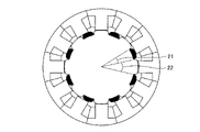
- FIG. 20 is a cross-sectional view of the rotary electric machine 100 according to the fourth embodiment.
- the rotor 2 is attached to the rotor core 3 and the permanent magnet 4 attached to the surface of the rotor core 3 as in the configuration of the first embodiment. It is configured to have and.
- the permanent magnet portion angle 21 and the convex portion angle 22 are shown so that the ratio of the widths of the permanent magnet 4 and the convex portion 16 can be expressed.
- the permanent magnet portion angle 21 is an angle between two straight lines connecting both ends of the line segment forming the maximum circumferential length of each permanent magnet 4 and the center of the rotation axis.
- the convex portion angle 22 is an angle between two straight lines connecting both ends of the line segment forming the maximum circumferential length of the convex portion 16 and the center of the rotation axis.
- the permanent magnet portion angle 21 and the convex portion angle 22 may be different. Even if the permanent magnet portion angle 21 and the convex portion angle 22 are different, the unbalanced magnetic attraction force is not affected as long as the configuration of the first embodiment is satisfied.
- the angle 21 of the permanent magnet portion is increased, the amount of magnetic flux generated by the permanent magnet 4 can be increased.
- the convex portion angle 22 is increased, the amount of field magnetic flux due to the field winding F can be increased. Since the rotary electric machine 100 according to the fourth embodiment has the above configuration, the magnetic flux amount and the field magnetic flux amount can be adjusted.
- Embodiment 5 The rotary electric machine 100 according to the fifth embodiment is also an example of the rotary electric machine 100 according to the present disclosure technique.
- the same reference numerals are used for the elements common to the above-described embodiments, and duplicate description will be omitted as appropriate.
- FIG. 21 is a bird's-eye view of the entire rotary electric machine according to the fifth embodiment.
- the A phase, the B phase, and the C phase of the armature winding are field windings as in the configuration of the stator 1 of the first embodiment. It is configured with F in between.
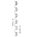
- FIG. 22 is a bird's-eye view of the rotor 2 according to the fifth embodiment.
- the rotor 2 has a convex rotor unit 28 and a permanent magnet rotor unit 29, and the convex rotor unit 28 and the permanent magnet rotor The units 29 are assembled side by side in the axial direction.
- the permanent magnet rotor unit 29 has a pole formed by the permanent magnet 4.
- the permanent magnet 4 may be embedded in the core 18 as shown in the configuration of the second embodiment.
- the convex rotor unit 28 is composed of only the convex portions 16 of the rotor core, and in the example shown in FIG. 22, the number of the convex portions 16 is half the number of the permanent magnets 4.
- This disclosed technology can be applied to drive motors such as EVs and has industrial applicability.
- stator 1 stator, 2 rotor, 3 rotor core, 4 permanent magnets, 5 shafts, 6 bearings, 7 stator cores, 8 coils, 9 stator brackets, 10 covers, 11 core backs, 12 teeth, 13 slots, 16 Convex part, 18 core, 19 convex part void length, 20 permanent magnet part void length, 21 permanent magnet part angle, 22 convex part angle, 28 convex rotor unit, 29 permanent magnet rotor unit, 100 permanent magnet, F field Magnetic winding.
Landscapes
- Engineering & Computer Science (AREA)
- Power Engineering (AREA)
- Permanent Field Magnets Of Synchronous Machinery (AREA)
- Synchronous Machinery (AREA)
- Permanent Magnet Type Synchronous Machine (AREA)
Priority Applications (5)
| Application Number | Priority Date | Filing Date | Title |
|---|---|---|---|
| JP2022575022A JP7387034B2 (ja) | 2021-01-18 | 2021-01-18 | 回転電機 |
| PCT/JP2021/001392 WO2022153517A1 (ja) | 2021-01-18 | 2021-01-18 | 回転電機 |
| US18/266,812 US12531450B2 (en) | 2021-01-18 | 2021-01-18 | Rotating electric machine |
| DE112021006828.8T DE112021006828T5 (de) | 2021-01-18 | 2021-01-18 | Rotierende elektrische maschine |
| CN202180089314.1A CN116746039A (zh) | 2021-01-18 | 2021-01-18 | 旋转电机 |
Applications Claiming Priority (1)
| Application Number | Priority Date | Filing Date | Title |
|---|---|---|---|
| PCT/JP2021/001392 WO2022153517A1 (ja) | 2021-01-18 | 2021-01-18 | 回転電機 |
Publications (1)
| Publication Number | Publication Date |
|---|---|
| WO2022153517A1 true WO2022153517A1 (ja) | 2022-07-21 |
Family
ID=82448263
Family Applications (1)
| Application Number | Title | Priority Date | Filing Date |
|---|---|---|---|
| PCT/JP2021/001392 Ceased WO2022153517A1 (ja) | 2021-01-18 | 2021-01-18 | 回転電機 |
Country Status (5)
| Country | Link |
|---|---|
| US (1) | US12531450B2 (https=) |
| JP (1) | JP7387034B2 (https=) |
| CN (1) | CN116746039A (https=) |
| DE (1) | DE112021006828T5 (https=) |
| WO (1) | WO2022153517A1 (https=) |
Families Citing this family (2)
| Publication number | Priority date | Publication date | Assignee | Title |
|---|---|---|---|---|
| CN115917926A (zh) * | 2020-05-29 | 2023-04-04 | 三菱电机株式会社 | 电磁设备以及使用电磁设备的飞机 |
| US20240223045A1 (en) * | 2022-12-30 | 2024-07-04 | Tynergy LLC | Apparatus, system, and method for an electromechanical kinetic motor |
Citations (2)
| Publication number | Priority date | Publication date | Assignee | Title |
|---|---|---|---|---|
| JP2017135863A (ja) * | 2016-01-28 | 2017-08-03 | 三菱電機株式会社 | ハイブリッド界磁式ダブルギャップ同期機 |
| JP2019149891A (ja) * | 2018-02-27 | 2019-09-05 | 三菱電機株式会社 | ハイブリッド界磁式ダブルギャップ同期機 |
Family Cites Families (8)
| Publication number | Priority date | Publication date | Assignee | Title |
|---|---|---|---|---|
| US3346793A (en) * | 1963-07-26 | 1967-10-10 | Hitachi Ltd | Starting method for double speed salient-pole type synchronous machines |
| JP5310085B2 (ja) | 2009-02-25 | 2013-10-09 | 株式会社デンソー | ハイブリッド励磁ipmモータ |
| GB2468695B (en) * | 2009-03-18 | 2011-02-09 | Imra Europ S A S Uk Res Ct | An electrical machine |
| JPWO2013073263A1 (ja) * | 2011-11-14 | 2015-04-02 | 株式会社安川電機 | モータおよびモータシステム |
| US9502931B2 (en) * | 2012-03-23 | 2016-11-22 | Asmo Co., Ltd. | Brushless motor |
| JP2015042038A (ja) | 2013-08-20 | 2015-03-02 | 株式会社小松製作所 | 回転電機 |
| JP6823318B2 (ja) | 2017-03-31 | 2021-02-03 | ダイキン工業株式会社 | 回転電気機械装置 |
| JP6898836B2 (ja) * | 2017-12-05 | 2021-07-07 | 株式会社豊田中央研究所 | 回転電機 |
-
2021
- 2021-01-18 WO PCT/JP2021/001392 patent/WO2022153517A1/ja not_active Ceased
- 2021-01-18 JP JP2022575022A patent/JP7387034B2/ja active Active
- 2021-01-18 US US18/266,812 patent/US12531450B2/en active Active
- 2021-01-18 DE DE112021006828.8T patent/DE112021006828T5/de active Pending
- 2021-01-18 CN CN202180089314.1A patent/CN116746039A/zh active Pending
Patent Citations (2)
| Publication number | Priority date | Publication date | Assignee | Title |
|---|---|---|---|---|
| JP2017135863A (ja) * | 2016-01-28 | 2017-08-03 | 三菱電機株式会社 | ハイブリッド界磁式ダブルギャップ同期機 |
| JP2019149891A (ja) * | 2018-02-27 | 2019-09-05 | 三菱電機株式会社 | ハイブリッド界磁式ダブルギャップ同期機 |
Also Published As
| Publication number | Publication date |
|---|---|
| DE112021006828T5 (de) | 2023-11-02 |
| CN116746039A (zh) | 2023-09-12 |
| US12531450B2 (en) | 2026-01-20 |
| US20240055920A1 (en) | 2024-02-15 |
| JP7387034B2 (ja) | 2023-11-27 |
| JPWO2022153517A1 (https=) | 2022-07-21 |
Similar Documents
| Publication | Publication Date | Title |
|---|---|---|
| JP4723118B2 (ja) | 回転電機及びこの回転電機を用いた滑車駆動装置 | |
| KR100983862B1 (ko) | 회전전기기계 | |
| JP4722309B2 (ja) | 回転電機及びこの回転電機を用いた滑車駆動装置 | |
| JP3633106B2 (ja) | スイッチドリラクタンスモータ | |
| JP6709712B2 (ja) | 同期リラクタンス型回転電機 | |
| CN108134494A (zh) | 旋转电机 | |
| JP6561692B2 (ja) | 回転電機 | |
| JPWO2014115435A1 (ja) | 永久磁石式回転電機 | |
| JP2018082600A (ja) | ダブルロータ型の回転電機 | |
| JP6760014B2 (ja) | 回転電機 | |
| JP7159800B2 (ja) | 回転電機 | |
| JP7387034B2 (ja) | 回転電機 | |
| JPWO2021131071A1 (ja) | ハイブリッド界磁式ダブルギャップ同期機および駆動システム | |
| CN113615041B (zh) | 旋转电机 | |
| JP6895909B2 (ja) | ハイブリッド界磁式ダブルギャップ同期機 | |
| JP2013132154A (ja) | 回転電機および回転電機のロータ | |
| US20120112598A1 (en) | Electrical machine stator assembly | |
| US12401240B2 (en) | Rotary electric machine including rotor with skew and stator in which top width of teeth is set based on skew angle | |
| JP6854875B1 (ja) | 回転電機 | |
| JP2015162983A (ja) | スイッチトリラクタンスモータ | |
| JP2017063594A (ja) | ブラシレスモータ | |
| CN112821701B (zh) | 一种单相电机 | |
| JP2019140789A (ja) | 回転電機 | |
| WO2019009195A1 (ja) | コンシクエント型モータ | |
| JP2024141807A (ja) | 固定子、および、電動機または発電機 |
Legal Events
| Date | Code | Title | Description |
|---|---|---|---|
| 121 | Ep: the epo has been informed by wipo that ep was designated in this application |
Ref document number: 21919410 Country of ref document: EP Kind code of ref document: A1 |
|
| ENP | Entry into the national phase |
Ref document number: 2022575022 Country of ref document: JP Kind code of ref document: A |
|
| WWE | Wipo information: entry into national phase |
Ref document number: 18266812 Country of ref document: US |
|
| WWE | Wipo information: entry into national phase |
Ref document number: 202180089314.1 Country of ref document: CN |
|
| WWE | Wipo information: entry into national phase |
Ref document number: 112021006828 Country of ref document: DE |
|
| 122 | Ep: pct application non-entry in european phase |
Ref document number: 21919410 Country of ref document: EP Kind code of ref document: A1 |
|
| WWG | Wipo information: grant in national office |
Ref document number: 18266812 Country of ref document: US |