WO2022145299A1 - キサゲ加工を行うロボットシステム、方法、及びコンピュータプログラム - Google Patents
キサゲ加工を行うロボットシステム、方法、及びコンピュータプログラム Download PDFInfo
- Publication number
- WO2022145299A1 WO2022145299A1 PCT/JP2021/047417 JP2021047417W WO2022145299A1 WO 2022145299 A1 WO2022145299 A1 WO 2022145299A1 JP 2021047417 W JP2021047417 W JP 2021047417W WO 2022145299 A1 WO2022145299 A1 WO 2022145299A1
- Authority
- WO
- WIPO (PCT)
- Prior art keywords
- force
- robot
- scraper
- target value
- processor
- Prior art date
- Legal status (The legal status is an assumption and is not a legal conclusion. Google has not performed a legal analysis and makes no representation as to the accuracy of the status listed.)
- Ceased
Links
Images









Classifications
-
- B—PERFORMING OPERATIONS; TRANSPORTING
- B26—HAND CUTTING TOOLS; CUTTING; SEVERING
- B26D—CUTTING; DETAILS COMMON TO MACHINES FOR PERFORATING, PUNCHING, CUTTING-OUT, STAMPING-OUT OR SEVERING
- B26D5/00—Arrangements for operating and controlling machines or devices for cutting, cutting-out, stamping-out, punching, perforating, or severing by means other than cutting
- B26D5/005—Computer numerical control means
-
- B—PERFORMING OPERATIONS; TRANSPORTING
- B25—HAND TOOLS; PORTABLE POWER-DRIVEN TOOLS; MANIPULATORS
- B25J—MANIPULATORS; CHAMBERS PROVIDED WITH MANIPULATION DEVICES
- B25J11/00—Manipulators not otherwise provided for
- B25J11/005—Manipulators for mechanical processing tasks
-
- B—PERFORMING OPERATIONS; TRANSPORTING
- B23—MACHINE TOOLS; METAL-WORKING NOT OTHERWISE PROVIDED FOR
- B23D—PLANING; SLOTTING; SHEARING; BROACHING; SAWING; FILING; SCRAPING; LIKE OPERATIONS FOR WORKING METAL BY REMOVING MATERIAL, NOT OTHERWISE PROVIDED FOR
- B23D79/00—Methods, machines, or devices not covered elsewhere, for working metal by removal of material
- B23D79/02—Machines or devices for scraping
-
- B—PERFORMING OPERATIONS; TRANSPORTING
- B25—HAND TOOLS; PORTABLE POWER-DRIVEN TOOLS; MANIPULATORS
- B25J—MANIPULATORS; CHAMBERS PROVIDED WITH MANIPULATION DEVICES
- B25J13/00—Controls for manipulators
- B25J13/08—Controls for manipulators by means of sensing devices, e.g. viewing or touching devices
- B25J13/085—Force or torque sensors
-
- B—PERFORMING OPERATIONS; TRANSPORTING
- B25—HAND TOOLS; PORTABLE POWER-DRIVEN TOOLS; MANIPULATORS
- B25J—MANIPULATORS; CHAMBERS PROVIDED WITH MANIPULATION DEVICES
- B25J9/00—Program-controlled manipulators
- B25J9/16—Program controls
- B25J9/1628—Program controls characterised by the control loop
- B25J9/1633—Program controls characterised by the control loop compliant, force, torque control, e.g. combined with position control
-
- B—PERFORMING OPERATIONS; TRANSPORTING
- B25—HAND TOOLS; PORTABLE POWER-DRIVEN TOOLS; MANIPULATORS
- B25J—MANIPULATORS; CHAMBERS PROVIDED WITH MANIPULATION DEVICES
- B25J9/00—Program-controlled manipulators
- B25J9/16—Program controls
- B25J9/1679—Program controls characterised by the tasks executed
- B25J9/1684—Tracking a line or surface by means of sensors
-
- B—PERFORMING OPERATIONS; TRANSPORTING
- B26—HAND CUTTING TOOLS; CUTTING; SEVERING
- B26D—CUTTING; DETAILS COMMON TO MACHINES FOR PERFORATING, PUNCHING, CUTTING-OUT, STAMPING-OUT OR SEVERING
- B26D3/00—Cutting work characterised by the nature of the cut made; Apparatus therefor
- B26D3/08—Making a superficial cut in the surface of the work without removal of material, e.g. scoring, incising
-
- G—PHYSICS
- G05—CONTROLLING; REGULATING
- G05B—CONTROL OR REGULATING SYSTEMS IN GENERAL; FUNCTIONAL ELEMENTS OF SUCH SYSTEMS; MONITORING OR TESTING ARRANGEMENTS FOR SUCH SYSTEMS OR ELEMENTS
- G05B2219/00—Program-control systems
- G05B2219/30—Nc systems
- G05B2219/45—Nc applications
- G05B2219/45058—Grinding, polishing robot
-
- G—PHYSICS
- G05—CONTROLLING; REGULATING
- G05B—CONTROL OR REGULATING SYSTEMS IN GENERAL; FUNCTIONAL ELEMENTS OF SUCH SYSTEMS; MONITORING OR TESTING ARRANGEMENTS FOR SUCH SYSTEMS OR ELEMENTS
- G05B2219/00—Program-control systems
- G05B2219/30—Nc systems
- G05B2219/45—Nc applications
- G05B2219/45096—Polishing manipulator
Definitions
- a robot system that performs a scraping process to flatten the surface of a work includes a robot that moves a scraper that scrapes the surface and a control device that controls the robot, and the control device is a robot.
- the robot By moving the scraper against the surface while pressing it in the direction along the surface, the robot performs the shaving process, and the robot repeatedly increases or decreases the pressing force that presses the scraper against the surface while the shaving processing is being performed.
- the position of the depth of scraping the surface is repeatedly increased or decreased.
- the robot system 10 includes a robot 12, a force sensor 14, a scraper 16, and a control device 18.
- the robot 12 is a vertical articulated robot and has a robot base 20, a swivel body 22, a lower arm portion 24, an upper arm portion 26, and a wrist portion 28.
- the robot base 20 is fixed on the floor of the work cell.
- the swivel body 22 is provided on the robot base 20 so as to be able to swivel around the vertical axis.
- the lower arm portion 24 is rotatably provided on the swivel body 22 around a horizontal axis
- the upper arm portion 26 is rotatably provided on the tip portion of the lower arm portion 24.
- the wrist portion 28 has a wrist base 28a rotatably provided at the tip of the upper arm portion 26 and a wrist flange 28b provided on the wrist base 28a so as to be rotatable around the wrist axis A1. ..
- Servo motors 34 are provided on each component of the robot 12 (robot base 20, swivel body 22, lower arm 24, upper arm 26, wrist 28). These servomotors 34 rotate each movable element of the robot 12 (swivel body 22, lower arm 24, upper arm 26, wrist 28, wrist flange 28b) around the drive shaft in response to a command from the control device 18. Move it. As a result, the robot 12 can move the scraper 16 and arrange it in an arbitrary position and posture.
- the scraper 16 is fixed to the tip of the force sensor 14 and scrapes the surface of the work W for scraping.
- the scraper 16 has a flexible handle portion 30 and a blade portion 32 fixed to the tip end portion of the handle portion 30.
- the base end portion of the handle portion 30 is fixed to the tip end portion of the force sensor 14, and is connected to the wrist flange 28b of the robot 12 via the force sensor 14.
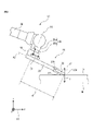
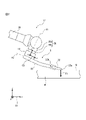
- FIG. 4 shows a state in which the robot 12 presses the tip 32a of the blade portion 32 of the scraper 16 against the surface Q of the work W.
- the reaction force F'of the pressing force F passes from the surface Q via the scraper 16. It is applied to the force sensor 14.
- Each of the strain gauges of the force sensor 14 transmits the detection data corresponding to the force acting on the force sensor 14 to the control device 18.
- the processor 40 acts on the force sensor 14 at this time, and the force f in the x-axis, y-axis, and z-axis directions of the sensor coordinate system C3.
- the torque ⁇ in the directions around the x-axis, around the y-axis, and around the z-axis.
- the processor 40 has a magnitude of reaction force F'acting on the tip 32a of the blade portion 32 in a direction orthogonal to the surface Q based on the force f and the torque ⁇ and the state data CD of the scraper 16 at this time. Is calculated.
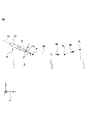
- a plurality of teaching points TP 1 , TP 2 and TP 3 for positioning the tip 32a (that is, TCP) of the scraper 16 in order to perform scraping are known positions in the robot coordinate system C1. It is set along the surface Q of the work W positioned at.
- the teaching point TP 2 is set at a position separated to the right of the teaching point TP 1
- the teaching point TP 3 is set at a position separated to the upper right of the teaching point TP 2 . ..
- the positions of the teaching points TP 1 and TP 2 in the robot coordinate system C1 in the z-axis direction are substantially the same as each other.
- the processor 40 When scraping, the processor 40 starts the position control ⁇ and generates the position control command PC n for moving the scraper 16 to the teaching point TP n by the robot 12.
- the processor 40 positions the scraper 16 in the order of teaching points TP 1 ⁇ TP 2 ⁇ TP 3 by operating each servomotor 34 of the robot 12 according to the position control command PC n .
- the processor 40 moves the scraper 16 (specifically, the tip 32a) along the movement path MP defined by the plurality of teaching points TP n .
- the processor 40 moves the scraper 16 (or the wrist flange 28b) along the surface Q in the direction MD of the movement path MP according to the position control command PC n , and moves the scraper 16 to the work W according to the force control command FC. It is moved in the direction of approaching or separating from the surface Q of the robot (that is, the z-axis direction of the robot coordinate system C1).
- the processor 40 generates a speed command FC V_0 to control the pressing force F to the target value ⁇ , and by adding the speed command FC V_2 to the speed command PC V_2 to the servomotor 34, the scraper 16 is directed toward the surface Q (that is,). , Downward) at the speed VF_0 corresponding to (specifically, matching) the speed command FC V_0 .
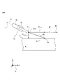
- the robot 12 moves the scraper 16 in the direction MD'in FIG. 6 after passing through the teaching point TP1.
- the distances in the x-axis and z-axis directions of the robot coordinate system C1 between the teaching point TP1 and the position P1 in FIG. 7 are the distances x1 and z1, respectively, the distances x1 and z1 and the speeds.
- the command PC V_2 (speed VP_2 ) and the speed command FC V_0 (speed VF_0 ) satisfy the following equation (1).
- the angle ⁇ 2 can be set in a desired range (for example, for example). It can be controlled from 15 ° to 35 °).
- the maximum value of the velocity command FC V_1 (that is, the velocity VF_1 ) generated while the scraper 16 is in contact with the surface Q is the velocity command FC V_1 generated before the scraper 16 is in contact with the surface Q (that is, the velocity VF_1 ). That is, it can be set larger than the speed VF_0 ).
- the processor 40 moves to the right along the surface Q while pressing the scraper 16 with the pressing force F having a size corresponding to the target value ⁇ by the robot 12, whereby the surface Q is moved by the tip 32a of the scraper 16. Perform scraping.
- the processor 40 terminates the force control ⁇ , while the position control command PC 3 for moving the scraper 16 to the teaching point TP 3 . To generate. Then, the processor 40 moves the scraper 16 to the upper right toward the teaching point TP 3 by operating the robot 12 according to the position control command PC 3 .
- the scraper 16 moves upward to the right on the orbit TR inclined so as to form an angle ⁇ 3 ( ⁇ 90 °) with respect to the surface Q of the work W, and the tip 32a of the scraper 16 is on the surface at the position P2. Separate from Q. In this way, the surface Q is scraped by the scraper 16 from the position P1 to the position P2 over a distance x2, and scraping is completed.
- the coordinates of the position P2 in the x-axis direction of the robot coordinate system C1 are substantially the same as the teaching point TP2. After that, the scraper 16 reaches the teaching point TP 3 (or a position immediately below the teaching point TP 3).
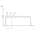
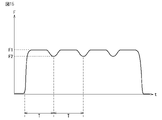
- FIG. 8 shows an example of the time change characteristic of the pressing force F during scraping.
- the pressing force F is repeatedly increased or decreased between the first force F1 and the second force F2 (> 0) smaller than the first force F1 during scraping. It is changing.
- the processor 40 increases or decreases the pressing force F as shown in FIG. 8 by the force control ⁇ executed during scraping.
- the processor 40 generates the force command FC F as the force control command FC as follows. That is, after the start of the force control ⁇ , the processor 40 generates a force command FC F that specifies the initial target value ⁇ 0 of the pressing force F, and operates the robot 12 in accordance with the force command FC F. As a result, the scraper 16 comes into contact with the surface Q at the position P1 as shown in FIG. 7, the pressing force F begins to increase, and reaches the second force F2 at the time point t1.
- the processor 40 generates a force command FC F for increasing the pressing force F by the amount of change ⁇ F from the time point t 1 at a predetermined time ⁇ 1 and then decreasing the pressing force F by the amount of change ⁇ F at a predetermined time ⁇ 2 .
- the above-mentioned initial target value ⁇ 0 may be set to a force F1 or F2, or may be set to any force value.
- the processor 40 may generate the force command FC F as the force control command FC as follows. That is, after the start of the force control ⁇ , the processor 40 generates a force command FC F for designating the first target value ⁇ 1-2 corresponding to the first force F1. By operating the robot 12 according to this force command FC F , the scraper 16 abuts on the surface Q at the position P1, the pressing force F reaches the second force F2 at the time point t1, and then at the time point t2. Reach the first force F1.
- ⁇ 2_2 ⁇ F2 the pressing force F does not reach the second target value ⁇ 2_2 at the time point t3, and the processor 40 uses the processor 40 before the pressing force F reaches the second target value ⁇ 2_2 .
- the force command FC F that specifies the target value ⁇ 1_2 of 1 will be generated.
- the processor 40 generates a force command FC F so that the target value ⁇ of the pressing force F changes with time with the time change characteristic corresponding to the characteristic shown in FIG. You may.
- the processor 40 generates a force command FC F so as to change the target value ⁇ stepwise with time in a predetermined control cycle T'( ⁇ T).
- the target value ⁇ can be periodically changed between the first target value ⁇ 1 and the second target value ⁇ 2 so as to have a time change characteristic corresponding to the characteristic shown in FIG. can.
- the processor 40 executes force control ⁇ while executing scraping, and repeatedly increases / decreases the target value ⁇ in the force control ⁇ to increase / decrease the pressing force F.
- the processor 40 sets the target value ⁇ as the first target value ⁇ 1 ( ⁇ 1_1 , ⁇ 1_1 ) and the second target value ⁇ 2 ( ⁇ 2_1 , ⁇ 2_1 ). It is changing between.
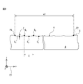
- the pressing force F can be controlled with high accuracy so as to change with time with the characteristics shown in FIG. Therefore, the depth Z of the recess R can be managed with high accuracy.
- the processor 40 executes the position control ⁇ together with the force control ⁇ to move the scraper 16 in the direction MD while pressing the scraper 16 against the surface Q. According to this configuration, the trajectory TR of the scraper 16 can be controlled with high accuracy. Further, in the present embodiment, the processor 40 increases / decreases the pressing force F periodically (specifically, in the period T). According to this configuration, it is possible to form recesses R in which valley portions En are lined up at equal intervals in the x-axis direction of the robot coordinate system C1.
- the above-mentioned first target value ⁇ 1 causes the handle portion 30 to bend when the blade portion 32 is pressed against the surface Q by the first force F1 during scraping. It may be defined as a value that can be used.
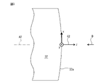
- FIG. 11 schematically shows a state in which the handle portion 30 is bent during scraping.
- the robot 12 presses the tip 32a of the scraper 16 against the surface Q with the first force F1, whereby the handle portion 30 of the scraper 16 is curved so as to bulge downward. It is bent.
- the second target value ⁇ 2 ( ⁇ 2_1 , ⁇ 2_1 , ⁇ F) is set so that the handle portion 30 of the scraper 16 bends even when the scraper 16 is pressed against the surface Q by the second force F2. You may.
- the memory 42 may store the target value setting program PG1 for changing the target value ⁇ as described above in advance.
- the processor 40 determines the target value ⁇ according to the target value setting program PG1 and generates the force command FC F for designating the target value ⁇ .
- the form for increasing or decreasing the pressing force F (target value ⁇ ) during scraping is not limited to the example shown in FIG.
- other modes for increasing or decreasing the pressing force F (target value ⁇ ) will be described with reference to FIGS. 12 to 15.
- the processor 40 changes the pressing force F between the first force F1 and the second force F2 ( ⁇ F1) in the period T.
- the processor 40 increases the pressing force F by the amount of change ⁇ F from the time point t 1 at the time ⁇ 1 , maintains it for a predetermined time ⁇ 3 , and then decreases it by the amount of change ⁇ F at the time ⁇ 2 .
- the processor 40 again designates the first target value ⁇ 1-2 with the force command FCF .
- the processor 40 repeats the cycle of designating the second target value ⁇ 2_2 after the time ⁇ 1 + ⁇ 3 and designating the first target value ⁇ 1-2 after the time ⁇ 2 in the force command FC F.
- the pressing force F can be changed in the period T between the first force F1 and the second force F2.
- the processor 40 controls the target value ⁇ of the pressing force F in the force command FC F so as to correspond to the time change characteristic shown in FIG. 13 in the control cycle T'( ⁇ T). You may change the time step by step.
- a recess R having a valley portion En extending linearly in parallel with the x-axis of the robot coordinate system C1 can be formed.
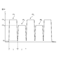
- the processor 40 changes the peak value of the first force F1 every cycle T. Specifically, the processor 40 maintains the pressing force F at the force F1 _A in the waveform of the second m-1st (m is a positive integer) peak FP 2m-1 in FIG. In the waveform of the second peak FP 2m , the pressing force F is maintained at the force F1 _B ( ⁇ F1 _A ).
- a first valley portion En_A extending linearly and a second valley portion En_B having a depth shallower than the first valley portion En_A and extending linearly are used.
- a recess R having the above can be formed.
- the processor 40 maintains the pressing force F at the force F1 _B in the waveform of the second m-1st peak FP 2m-1 in FIG. 14, while the pressing force F is the waveform of the second peak FP 2m in FIG.
- a force command FC F may be generated to maintain F at force F1 _A .
- the processor 40 maintains the pressing force F at the first force F1 for a predetermined time as in FIG. 13, but the second force F2 shown in FIG. 15 is shown in FIG. It is set higher than the second force F2 shown in 13. According to the example shown in FIG. 15, the depth F of the mountain portion Gn of the formed recess R can be made relatively large.
- the processor 40 can control the pressing force F so as to have the time change characteristic shown in FIG. 15 by executing the force control ⁇ described with reference to FIG.
- the processor 40 may automatically determine at least one of the machining conditions MC according to the input data from the operator.
- the machining condition MC is the length of the recess R to be formed in addition to the angles ⁇ 2, the distances x1 and z1, the speed command PC V_2 (speed VP_2 ), and the speed command FC V_0 (speed VF_0 ) shown in FIG. x2, the number k and the depth Z (FIG. 9) of the valley portions En (or mountain portions G n ) formed in the recess R, and the two mountain portions G n and G adjacent to each other in the x-axis direction of the robot coordinate system C1.
- the distance X (FIG.
- the operator operates the input device 46 to input the speed command PC V_2 (speed VP_2 ), the length x2 of the recess R, the number k, and the depth Z as the machining condition MC.
- the processor 40 automatically determines the target value ⁇ from the input depth Z.
- the memory 42 stores data in which the first target value ⁇ 1 and the depth Z of the valley portion En (or the depth Z of the second target value ⁇ 2 and the mountain portion G n ) are associated with each other and stored.
- the table DT1 may be stored in advance. In this case, the processor 40 can automatically determine the target value ⁇ by searching the data table DT1 for the target value ⁇ 1 (or ⁇ 2 ) corresponding to the input depth Z.
- the operator may input the gain Ga as the machining condition MC instead of the speed command PC V_2 (speed VP_2 ) described above.
- the processor 40 may automatically determine the period T from the input gain Ga.
- the memory 42 may store in advance the data table DT2 in which the gain Ga and the period T are stored in association with each other.
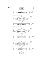
- step S12 the processor 40 determines whether or not the scraper 16 has reached the teaching point TP1.
- the servomotor 34 of the robot 12 is provided with a rotation detector (encoder, Hall element, etc.) that detects the rotation (specifically, the rotation angle or the rotation position) of the servomotor 34.
- the processor 40 acquires the position data of the scraper 16 (specifically, TCP) in the robot coordinate system C1 based on the feedback from the rotation detector, and from the position data, the scraper 16 reaches the teaching point TP1. It can be determined whether or not it has been reached. If the processor 40 determines that the scraper 16 has reached the teaching point TP 1 (that is, YES), the processor 40 proceeds to step S13, while the processor 16 determines that the teaching point TP 1 has not been reached (that is, NO). If so, the step S12 is looped.
- TCP position data of the scraper 16
- FIG. 19 shows the time change characteristic of the pressing force F in the first force control ⁇ 1.
- the processor 40 does not increase or decrease the pressing force F as shown in FIGS. 8, 12 to 15, and the predetermined target value ⁇ 3
- step S14 the processor 40 determines whether the scraper 16 (or wrist flange 28b) has reached the position corresponding to the teaching point TP2 . If the processor 40 determines YES, the processor proceeds to step S15, while if it determines NO, the processor 40 loops step S14.
- step S16 the processor 40 determines whether or not the scraper 16 has reached the teaching point TP 3 . If the determination is YES, the processor 40 proceeds to step S17, while if the determination is NO, the processor 40 loops step S16. Then, in step S17, the processor 40 ends the position control ⁇ .
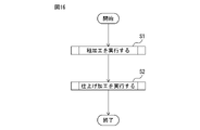
- step S2 the processor 40 executes finishing.
- the finishing process is to reduce the minute irregularities formed on the surface Q after roughing to a second dimension (for example, 5 ⁇ m) smaller than the first dimension and to make it function as the above-mentioned oil sump. This is scraping to form a recess.
- step S2 will be described with reference to FIG.
- the flow shown in FIG. 18 is different from the flow shown in FIG. 17 in step S13'.
- the processor 40 starts the second force control ⁇ 2 in step S13'.
- the processor 40 repeatedly increases or decreases the pressing force F by executing the force control ⁇ described with reference to FIGS. 8 and 12 to 15 described above.
- the surface Q is scraped to increase the flatness of the surface Q to some extent by step S1 (roughing), and then step S2 (finishing) is executed. While further increasing the flatness of the surface Q, it is possible to form a recess R that functions as an oil sump as shown in FIG. As a result, the robot system 10 can automatically perform roughing and finishing in succession.
- step S2 may be executed first, and then step S2 may be executed. Further, the processor 40 may alternately and repeatedly execute steps S1 and S2 a plurality of times. The processor 40 executes the flow shown in FIG. 16 according to the target value setting program PG1 and the work program PG2 described above.
- the target value setting program PG1 is a computer program in which an algorithm for generating the target value ⁇ is defined, while the work program PG2 is the position data of the teaching point TPn , and the position control ⁇ and the force control ⁇ . It is a computer program that specifies the statement to execute.
- the target value setting program PG1 and the work program PG2 may be stored in the memory 42 as separate computer programs from each other, or may be integrated into one computer program and stored in the memory 42.
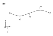
- the pressing force F is shown in FIG.
- the first force F1 is reached and the scraper 16 reaches the midpoint between the swing peak points P3 and P4
- the pressing force F reaches the second force F2 in FIG.
- the increase / decrease of F and the swing of the scraper 16 may be synchronized.
- the recesses R having the valley portions En arranged in a staggered pattern in the x-axis direction of the robot coordinate system C1 can be formed.
- the processor 40 executes the position control ⁇ , and the scraper 16 is set by the robot 12 at the teaching points TP 11 ⁇ TP 12 ⁇ TP 13 ⁇ TP 14 ⁇ TP 15 ⁇ TP 16 ... Move in order. As a result, the scraper 16 comes into contact with the surface Q at the teaching point TP 12 . After that, the processor 40 moves the wrist flange 28b of the robot 12 to the positions corresponding to the teaching points TP 13 , TP 14 , TP 15 and TP 16 in order, so that the scraper 16 is pressed against the surface Q and along the surface Q. And move it to the right. In this way, scraping can be performed.
- the first force F1 or the second force F2 may change in each period T.
- the force of 1 may be different from F1 i + 1 .
- the force sensor 14 may be inserted between the work cell and the robot base 20, for example, or may be provided at any part of the robot 12. Further, the force sensor 14 is not limited to the robot 12, and may be provided on the side of the work W. For example, the pressing force F can be detected by inserting the force sensor 14 between the work W and the mounting surface on which the work W is placed.
- the force sensor 14 is not limited to the 6-axis force sensor, and may be, for example, a 1-axis or 3-axis force sensor, or any sensor capable of detecting the pressing force F.
- the origin of the sensor coordinate system C3 is not limited to the center of the force sensor 14, and may be arranged at any position known to the force sensor 14, and each axis may be defined in any direction. ..
Landscapes
- Engineering & Computer Science (AREA)
- Mechanical Engineering (AREA)
- Robotics (AREA)
- Life Sciences & Earth Sciences (AREA)
- Forests & Forestry (AREA)
- General Engineering & Computer Science (AREA)
- Human Computer Interaction (AREA)
- Physics & Mathematics (AREA)
- Optics & Photonics (AREA)
- Manipulator (AREA)
- Milling, Broaching, Filing, Reaming, And Others (AREA)
- Machine Tool Sensing Apparatuses (AREA)
Abstract
Description
z1/x1=FCV_0/PCV_2=VF_0/VP_2 …(1)
θ2=tan-1(z1/x1)=tan-1(FCV_0/PCV_2)=tan-1(VF_0/VP_2) …(2)
12 ロボット
14 力センサ
16 スクレーパ
18 制御装置
40 プロセッサ
Claims (8)
- ワークの表面を平坦にするために削るキサゲ加工を行うロボットシステムであって、
前記表面を削るスクレーパを移動させるロボットと、
前記ロボットを制御する制御装置と、を備え、
前記制御装置は、
前記ロボットによって前記スクレーパを前記表面に押し付けながら該表面に沿う方向へ移動させることで、前記キサゲ加工を実行し、
前記キサゲ加工を実行している間、前記ロボットが前記スクレーパを前記表面に押し付ける押付力を繰り返し増減させるように該ロボットの位置を制御することで、前記表面を削る深さを繰り返し増減させる、ロボットシステム。 - 前記押付力を検出する力センサをさらに備え、
前記制御装置は、
前記キサゲ加工を実行している間、前記力センサの検出データに基づいて前記押付力を所定の目標値に制御する力制御を実行することによって、前記ロボットの前記位置を制御し、
前記力制御において前記目標値を繰り返し増減させることによって、前記押付力を増減させる、請求項1に記載のロボットシステム。 - 前記制御装置は、前記力制御において前記目標値を、第1の目標値と、該第1の目標値よりも小さい第2の目標値との間で変化させる、請求項2に記載のロボットシステム。
- 前記スクレーパは、
前記ロボットに連結された可撓性の柄部と、
前記柄部の先端に固定され、前記表面を削る刃部と、を有し、
前記第1の目標値は、前記刃部が該第1の目標値に対応する前記押付力で前記表面に押し付けられたときに前記柄部を撓ませることができる値として、定められる、請求項3に記載のロボットシステム。 - 前記制御装置は、前記表面に沿って予め定められた複数の教示点へ前記スクレーパを順に移動させる位置制御を、前記力制御とともに実行することで、前記キサゲ加工において前記スクレーパを前記沿う方向へ移動させる、請求項2~4のいずれか1項に記載のロボットシステム。
- 前記制御装置は、前記押付力を周期的に増減させる、請求項1~5のいずれか1項に記載のロボットシステム。
- ワークの表面を削るスクレーパを移動させるロボットを用いて、該表面を平坦にするために削るキサゲ加工の方法であって、
前記ロボットによって前記スクレーパを前記表面に押し付けながら該表面に沿う方向へ移動させることで、前記キサゲ加工を実行し、
前記キサゲ加工を実行している間、前記ロボットが前記スクレーパを前記表面に押し付ける押付力を繰り返し増減させるように該ロボットの位置を制御することで、前記表面を削る深さを繰り返し増減させる、方法。 - 請求項7に記載の方法をプロセッサに実行させるコンピュータプログラム。
Priority Applications (4)
| Application Number | Priority Date | Filing Date | Title |
|---|---|---|---|
| DE112021005623.9T DE112021005623T5 (de) | 2020-12-28 | 2021-12-21 | Robotersystem, verfahren und computerprogramm zur durchführung eines schabvorgangs |
| US18/266,863 US20240051171A1 (en) | 2020-12-28 | 2021-12-21 | Robot system, method, and computer program for performing scraping process |
| JP2022573017A JP7469518B2 (ja) | 2020-12-28 | 2021-12-21 | キサゲ加工を行うロボットシステム、方法、及びコンピュータプログラム |
| CN202180086481.0A CN116802019B (zh) | 2020-12-28 | 2021-12-21 | 进行刮研加工的机器人系统、方法以及计算机程序 |
Applications Claiming Priority (2)
| Application Number | Priority Date | Filing Date | Title |
|---|---|---|---|
| JP2020219442 | 2020-12-28 | ||
| JP2020-219442 | 2020-12-28 |
Publications (1)
| Publication Number | Publication Date |
|---|---|
| WO2022145299A1 true WO2022145299A1 (ja) | 2022-07-07 |
Family
ID=82260451
Family Applications (1)
| Application Number | Title | Priority Date | Filing Date |
|---|---|---|---|
| PCT/JP2021/047417 Ceased WO2022145299A1 (ja) | 2020-12-28 | 2021-12-21 | キサゲ加工を行うロボットシステム、方法、及びコンピュータプログラム |
Country Status (6)
| Country | Link |
|---|---|
| US (1) | US20240051171A1 (ja) |
| JP (1) | JP7469518B2 (ja) |
| CN (1) | CN116802019B (ja) |
| DE (1) | DE112021005623T5 (ja) |
| TW (1) | TWI894405B (ja) |
| WO (1) | WO2022145299A1 (ja) |
Families Citing this family (1)
| Publication number | Priority date | Publication date | Assignee | Title |
|---|---|---|---|---|
| US12350839B2 (en) * | 2020-09-08 | 2025-07-08 | Fanuc Corporation | Robot system, method, and computer program for performing scraping process |
Citations (6)
| Publication number | Priority date | Publication date | Assignee | Title |
|---|---|---|---|---|
| JPH05123921A (ja) * | 1991-02-20 | 1993-05-21 | Nippon Spindle Mfg Co Ltd | キサゲ加工方法及びその装置 |
| JPH071229A (ja) * | 1993-06-14 | 1995-01-06 | Mitsui Seiki Kogyo Co Ltd | M/cによるキサゲ方法 |
| JP2004042164A (ja) * | 2002-07-10 | 2004-02-12 | Gifu Univ | 柔軟な構造を特徴とする切削工具ホルダ及びその使用方法 |
| JP2010240809A (ja) * | 2009-04-10 | 2010-10-28 | Star Micronics Co Ltd | 自動キサゲ装置 |
| JP2016137551A (ja) * | 2015-01-28 | 2016-08-04 | ファナック株式会社 | ロボットを用いたキサゲ加工装置及びキサゲ加工方法 |
| JP2017131974A (ja) * | 2016-01-25 | 2017-08-03 | 株式会社シュルード設計 | 設置機械のきさげ加工装置、および、設置機械のきさげ加工方法 |
Family Cites Families (8)
| Publication number | Priority date | Publication date | Assignee | Title |
|---|---|---|---|---|
| US2810144A (en) * | 1952-08-27 | 1957-10-22 | Ray H Mcintosh | Broiler grate scrapers |
| CN1044059A (zh) * | 1989-11-30 | 1990-07-25 | 胡思伟 | 刮花机刮研机 |
| JPH08187620A (ja) * | 1992-06-30 | 1996-07-23 | Kyowa Kogyo Kk | キサゲ面形成装置 |
| JPH0663817A (ja) * | 1992-08-19 | 1994-03-08 | Micron Seimitsu Kk | 自動キサゲ装置 |
| JPH0970716A (ja) * | 1995-09-08 | 1997-03-18 | Hitachi Metals Ltd | 振動工具及び振動工具を装着した力制御ロボット |
| JP5845212B2 (ja) * | 2013-06-28 | 2016-01-20 | ファナック株式会社 | 視覚センサ及び力センサを備えたバリ取り装置 |
| MX2016003018A (es) * | 2013-09-11 | 2016-06-10 | Profilator Gmbh & Co Kg | Metodo de descortezado por generacion y dispositivo pertinente. |
| CN105583824B (zh) * | 2016-01-26 | 2017-05-24 | 清华大学 | 力控牵引和摆位的多自由度机械臂控制装置及其控制方法 |
-
2021
- 2021-12-03 TW TW110145255A patent/TWI894405B/zh active
- 2021-12-21 CN CN202180086481.0A patent/CN116802019B/zh active Active
- 2021-12-21 JP JP2022573017A patent/JP7469518B2/ja active Active
- 2021-12-21 WO PCT/JP2021/047417 patent/WO2022145299A1/ja not_active Ceased
- 2021-12-21 DE DE112021005623.9T patent/DE112021005623T5/de active Pending
- 2021-12-21 US US18/266,863 patent/US20240051171A1/en active Pending
Patent Citations (6)
| Publication number | Priority date | Publication date | Assignee | Title |
|---|---|---|---|---|
| JPH05123921A (ja) * | 1991-02-20 | 1993-05-21 | Nippon Spindle Mfg Co Ltd | キサゲ加工方法及びその装置 |
| JPH071229A (ja) * | 1993-06-14 | 1995-01-06 | Mitsui Seiki Kogyo Co Ltd | M/cによるキサゲ方法 |
| JP2004042164A (ja) * | 2002-07-10 | 2004-02-12 | Gifu Univ | 柔軟な構造を特徴とする切削工具ホルダ及びその使用方法 |
| JP2010240809A (ja) * | 2009-04-10 | 2010-10-28 | Star Micronics Co Ltd | 自動キサゲ装置 |
| JP2016137551A (ja) * | 2015-01-28 | 2016-08-04 | ファナック株式会社 | ロボットを用いたキサゲ加工装置及びキサゲ加工方法 |
| JP2017131974A (ja) * | 2016-01-25 | 2017-08-03 | 株式会社シュルード設計 | 設置機械のきさげ加工装置、および、設置機械のきさげ加工方法 |
Non-Patent Citations (1)
| Title |
|---|
| AKIBA, TAKUMI ET AL.: "Development of scraping robot", PROCEEDINGS OF THE 2013 JSME CONFERENCE ON ROBOTICS AND MECHATRONIC;S TSUKUBA, JAPAN; MAY 22-25, 2013, 21 May 2013 (2013-05-21) - 25 May 2013 (2013-05-25), JP, pages 1137 - 1138, XP009537878 * |
Also Published As
| Publication number | Publication date |
|---|---|
| DE112021005623T5 (de) | 2023-10-05 |
| US20240051171A1 (en) | 2024-02-15 |
| CN116802019A (zh) | 2023-09-22 |
| TWI894405B (zh) | 2025-08-21 |
| CN116802019B (zh) | 2025-08-12 |
| TW202228955A (zh) | 2022-08-01 |
| JPWO2022145299A1 (ja) | 2022-07-07 |
| JP7469518B2 (ja) | 2024-04-16 |
Similar Documents
| Publication | Publication Date | Title |
|---|---|---|
| JP7469487B2 (ja) | キサゲ加工を行うロボットシステム、方法、及びコンピュータプログラム | |
| JP6619395B2 (ja) | ロボットシステムおよびロボットの教示方法 | |
| US9207668B2 (en) | Method of and apparatus for automated path learning | |
| JP6705851B2 (ja) | 振動解析装置および振動解析方法 | |
| JP6582483B2 (ja) | ロボット制御装置およびロボットシステム | |
| CN105983970B (zh) | 机器人 | |
| US20240051138A1 (en) | Device, robot system, and method for determining position of recessed portion to be formed by scraping | |
| JP2021122923A (ja) | 制御方法、ロボット装置、ロボットシステム、および物品の製造方法 | |
| WO2022145299A1 (ja) | キサゲ加工を行うロボットシステム、方法、及びコンピュータプログラム | |
| Ochoa et al. | Impedance control architecture for robotic-assisted micro-drilling tasks | |
| JP2018069361A (ja) | 力制御座標軸設定装置、ロボットおよび力制御座標軸設定方法 | |
| US11951625B2 (en) | Control method for robot and robot system | |
| JP6088601B2 (ja) | 走行軸付きロボットにおけるツール先端の振れを抑制するロボット制御装置 | |
| TWI906441B (zh) | 進行刮削加工之機器人、機器人系統、進行刮削加工之方法及電腦程式 | |
| JP6705847B2 (ja) | 加工結果に基づいた学習制御を行うロボットシステム及びその制御方法 | |
| JP5961077B2 (ja) | ロボット制御装置およびロボット制御方法 | |
| JP4359808B2 (ja) | ロボット制御装置 | |
| JP2008130022A (ja) | 産業用ロボット制御装置 | |
| JPS5946758B2 (ja) | 自動作業機械の動作制御方法 | |
| WO2021241512A1 (ja) | ワークに対する作業をロボットに実行させる制御装置、ロボットシステム、及び制御方法 | |
| Bomfim et al. | A low cost methodology applied to remanufacturing of robotic manipulators | |
| Mizutani et al. | A novel haptic display based on curvature estimation and its application to a machining support robot | |
| JPS6180407A (ja) | 数値制御方法 |
Legal Events
| Date | Code | Title | Description |
|---|---|---|---|
| 121 | Ep: the epo has been informed by wipo that ep was designated in this application |
Ref document number: 21915159 Country of ref document: EP Kind code of ref document: A1 |
|
| ENP | Entry into the national phase |
Ref document number: 2022573017 Country of ref document: JP Kind code of ref document: A |
|
| WWE | Wipo information: entry into national phase |
Ref document number: 18266863 Country of ref document: US |
|
| WWE | Wipo information: entry into national phase |
Ref document number: 202180086481.0 Country of ref document: CN Ref document number: 112021005623 Country of ref document: DE |
|
| 122 | Ep: pct application non-entry in european phase |
Ref document number: 21915159 Country of ref document: EP Kind code of ref document: A1 |
|
| WWG | Wipo information: grant in national office |
Ref document number: 202180086481.0 Country of ref document: CN |