WO2022145179A1 - カテーテルの製造方法及びカテーテル - Google Patents
カテーテルの製造方法及びカテーテル Download PDFInfo
- Publication number
- WO2022145179A1 WO2022145179A1 PCT/JP2021/044950 JP2021044950W WO2022145179A1 WO 2022145179 A1 WO2022145179 A1 WO 2022145179A1 JP 2021044950 W JP2021044950 W JP 2021044950W WO 2022145179 A1 WO2022145179 A1 WO 2022145179A1
- Authority
- WO
- WIPO (PCT)
- Prior art keywords
- strand
- catheter
- wire
- intersection
- tip
- Prior art date
- Legal status (The legal status is an assumption and is not a legal conclusion. Google has not performed a legal analysis and makes no representation as to the accuracy of the status listed.)
- Ceased
Links
Images






Classifications
-
- A—HUMAN NECESSITIES
- A61—MEDICAL OR VETERINARY SCIENCE; HYGIENE
- A61M—DEVICES FOR INTRODUCING MEDIA INTO, OR ONTO, THE BODY; DEVICES FOR TRANSDUCING BODY MEDIA OR FOR TAKING MEDIA FROM THE BODY; DEVICES FOR PRODUCING OR ENDING SLEEP OR STUPOR
- A61M25/00—Catheters; Hollow probes
- A61M25/0009—Making of catheters or other medical or surgical tubes
- A61M25/0012—Making of catheters or other medical or surgical tubes with embedded structures, e.g. coils, braids, meshes, strands or radiopaque coils
-
- A—HUMAN NECESSITIES
- A61—MEDICAL OR VETERINARY SCIENCE; HYGIENE
- A61M—DEVICES FOR INTRODUCING MEDIA INTO, OR ONTO, THE BODY; DEVICES FOR TRANSDUCING BODY MEDIA OR FOR TAKING MEDIA FROM THE BODY; DEVICES FOR PRODUCING OR ENDING SLEEP OR STUPOR
- A61M25/00—Catheters; Hollow probes
- A61M25/0043—Catheters; Hollow probes characterised by structural features
- A61M25/005—Catheters; Hollow probes characterised by structural features with embedded materials for reinforcement, e.g. wires, coils, braids
-
- A—HUMAN NECESSITIES
- A61—MEDICAL OR VETERINARY SCIENCE; HYGIENE
- A61M—DEVICES FOR INTRODUCING MEDIA INTO, OR ONTO, THE BODY; DEVICES FOR TRANSDUCING BODY MEDIA OR FOR TAKING MEDIA FROM THE BODY; DEVICES FOR PRODUCING OR ENDING SLEEP OR STUPOR
- A61M25/00—Catheters; Hollow probes
- A61M25/0043—Catheters; Hollow probes characterised by structural features
- A61M25/0045—Catheters; Hollow probes characterised by structural features multi-layered, e.g. coated
Definitions
- the present invention relates to a method for manufacturing a catheter and a catheter.
- a catheter has been used for insertion into a tubular organ in the body such as a blood vessel.
- the catheter has a structure including an inner layer, a braid provided on the outer peripheral side of the inner layer, and an outer layer provided on the outer peripheral side of the braid, and has no inner layer and is provided with a braid on the inner peripheral side of the outer layer.
- the braided body has a function as a reinforcing material and is formed by knitting a metal wire made of tungsten or stainless steel.
- the braided body is composed of a plurality of first strands and a plurality of second strands intersecting the first strands.
- Patent Document 1 describes a method for manufacturing a catheter that cuts an excess portion of the first and second strands by irradiating the first and second strands with a laser beam. Patent Document 1 also describes that a bulging portion is formed by re-irradiating a sharp residual portion generated by the cutting with a laser beam.
- the first and second strands are irradiated with laser light to cut off the excess portion.
- the first strand and the second strand are liquefied by the heat of the laser beam, and a rounded bulge is formed by the surface tension at that time.
- the thickness of the tip portion of each strand is at the intersection adjacent to the tip portion. It can be larger than the thickness.
- An object of the present invention is to prevent the thickness of the tip of the braid from increasing more than the thickness of the intersection of the strands in the catheter manufacturing method and the catheter, and to prevent the outer layer from being uneven in the radial direction. Is to suppress.
- the method for manufacturing a catheter according to the present invention includes a braided body having a first wire, a second wire crossing the first wire, and an outer layer provided on the outer periphery of the braid.
- a cutting step for cutting and a removing step for removing the covering member from the outer peripheral side of the braided body are provided.
- the cutting step is performed from the outside of the covering member to the tip end side of the intersection of at least one of the first strand and the second strand of the braid. It is possible to irradiate the located portion with a laser beam to cut the one wire and weld the first wire and the second wire.
- the first wire and the second wire can be welded together with the cutting of one of the wires. Further, it is not necessary to join the first and second strands by laser irradiation in advance at the intersection before cutting the first and second strands by laser irradiation. This makes it possible to reduce the number of laser irradiations.
- the cutting step involves a portion of the braided body located on the distal end side of the intersection of the one strand, the first strand, and the first strand from the outside of the covering member. It is possible to irradiate the other strand of the second strand with a laser beam to cut the one strand and weld the first strand and the second strand.
- the solidified portion can increase the joint strength of the first wire and the second wire.
- the covering member is a combination of an inner covering portion and an outer covering portion which are overlapped in the radial direction and are made of different materials from each other, and the covering step is a sheet forming the inner covering portion. Is placed on the inner peripheral side of the inner member and the braided body, and then the long member having a C-shaped diameter cross section forming the outer covering portion is fitted from above the sheet to fit the inner member and the inner member. The outer peripheral side of the braided body may be covered with the covering member.
- the covering member can be configured to include a shrink tube.
- the covering member is more likely to be in close contact with the outer peripheral side end of the braided body, it is easier to further suppress the increase in thickness at the tip of one of the strands due to irradiation with laser light. ..
- the inner member is an inner layer forming the catheter.
- the presence of the inner layer makes it easy to pull out the wire rod, so that the catheter manufacturing work is easy. Can be done.
- the inner member is a jig.
- the catheter according to the present invention is a catheter including a braid having a first wire, a second wire intersecting with the first wire, and an outer layer provided on the outer periphery of the braid.
- the braided body is joined so that the first wire and the second wire intersect with each other in the radial direction so that one wire is arranged radially inside the other wire.
- the radial outer surface of the tip of the one wire protruding from the widthwise side surface of the portion of the other wire including the intersection to the tip side is the diameter of the other wire at the intersection. It is located at the same radial position as the outer surface of the direction or inside the radial direction.
- the radial outer surface of the tip of one strand is located at the same radial position as the radial outer surface of the other strand at the intersection, or inside the radial direction. Therefore, the thickness of the tip of one of the strands is equal to or less than the thickness of the intersection of the first strand and the second strand. As a result, it is not necessary to increase the thickness of the outer layer of the catheter so that the braid does not protrude from the outer peripheral surface of the outer layer, and it is possible to suppress non-uniformity in the radial direction of the outer peripheral surface of the outer layer.
- the first wire and the second wire may be formed of metal wires of the same metal material as each other.
- the tip of one of the strands may have a protruding portion on one side extending away from the intersection along the longitudinal direction of the other strand. ..
- the contact area between the end portion of the braided body and the inner member can be increased.
- the end portion of the braided body is less likely to come off from the inner layer.
- the tip of the other wire may have a protruding portion on the other side that protrudes from the intersection so as to protrude in the longitudinal direction of the other wire.
- the contact area between the end portion of the braided body and the inner member can be increased.
- the end portion of the braided body is less likely to come off from the inner layer.
- the catheter according to the present invention is a catheter including a braid having a first wire, a second wire intersecting with the first wire, and an outer layer provided on the outer periphery of the braid.
- the braided body is joined so that the first strand and the second strand are radially overlapped so that the first strand and the second strand are arranged at the intersection and one strand is arranged radially inside the other strand.
- the intersection has a recess on the tip end side of at least the radial outer surface, and the tip end portion of the one wire does not protrude from the side surface on the tip end side of the intersection.
- the thickness of the tip portion of one strand is the first strand and the second strand. It is possible to prevent the thickness from becoming larger than the thickness of the intersection of the strands. As a result, it is not necessary to increase the thickness of the outer layer of the catheter so that the braid does not protrude from the outer peripheral surface of the outer layer, and it is possible to suppress non-uniformity in the radial direction of the outer peripheral surface of the outer layer.
- the method for manufacturing a catheter and the catheter according to the present invention it is possible to suppress the thickness of the tip of the braid from increasing more than the thickness of the intersection of the strands, and the outer peripheral surface of the outer layer is non-uniform in the radial direction. Can be suppressed.
- FIG. 3 is a perspective view showing a state in which a part of the outer layer of the distal shaft is peeled off in the catheter shown in FIG. 2.
- FIG. 3 is a schematic cross-sectional view taken along the line AA of FIG. It is sectional drawing corresponding to FIG. 4 which shows the state which arranged the braided body on the outer periphery of the inner layer, and covered with the covering member from above.
- 5A is a view seen from the direction of the arrow A in FIG. 5A.
- (a) is a diagram showing a cutting line when the end of the braid is cut with a laser beam
- (b) is a diagram showing the end of the braid after cutting. be.
- a cutting step of irradiating a braided body with a laser beam to cut the first wire a coating removing step of removing a covering member, and removing an excess portion of the first wire. It is a figure which shows the wire removal process. It is an enlarged view which looked at the end part of the braided body after the wire removal process from the outside in the radial direction.
- the guide extension catheter 10 which is an example of the catheter of the embodiment, will be described with reference to FIGS. 1 to 10.
- the guide extension catheter 10 is used, for example, by inserting a lead-out portion from the guiding catheter 100 into the coronary artery 102 and leading out the stent delivery catheter 106 from the distal end P of the lead-out portion.
- the guiding catheter 100 is shown by a portion painted in black.
- the guide extension catheter 10 will be referred to as a catheter 10. Since the catheter 10 is used in the state shown in FIG. 1, the distal end P thereof is required to have flexibility so that it can be easily inserted into an organ such as a blood vessel.
- FIG. 2 is an overall view of the catheter 10.
- the catheter 10 is a long member and includes a tubular distal shaft 12 and a proximal shaft 50 connected to a proximal end of the distal shaft 12 and made of a metal wire.
- the distal end of the proximal shaft 50 is connected to a portion of the circumferential surface of the distal shaft 12 in the circumferential direction.
- the "proximal end side” means the posterior side (right side in FIG. 2) with respect to the direction in which the catheter 10 is inserted into the blood vessel.
- distal end side refers to the anterior side (left side in FIG. 2) with respect to the direction in which the catheter 10 is inserted into the blood vessel.
- FIG. 3 is a perspective view showing a state in which a part of the outer layer 30 of the distal shaft 12 is peeled off in the catheter 10.
- FIG. 4 is a schematic cross-sectional view taken along the line AA of FIG.
- the distal shaft 12 includes an inner layer 14 made of resin, a braided body 16 provided on the outer periphery of the inner layer 14, and an outer layer 30 provided on the outer periphery of the braided body 16 and having resin.
- the inner layer 14 corresponds to the inner member and forms the catheter 10.
- the inner layer 14 forms a lumen 15 for inserting another catheter inside.
- the resin material constituting the inner layer 14 is not particularly limited, but for example, polytetrafluoroethylene (PTFE) or the like is used.
- the inner layer 14 is not limited to a single-layer tube, and may be a multi-layer tube made of the same or different materials.
- the braided body 16 is a mesh-like braid of the first wire 17 and the second wire 18.
- a plurality of first strands 17 are wound around the outer layer 14 along the first direction inclined with respect to the longitudinal axis of the distal shaft 12.
- the plurality of second strands 18 are inclined with respect to the longitudinal axis of the distal shaft 12, and are wound around the outer layer 14 along the second direction intersecting the first direction.
- the first wire 17 and the second wire 18 are formed of metal wires of the same metal material such as tungsten and stainless steel.
- the cross section of the braided body 16 is schematically shown by a plurality of rectangular portions.
- the shape of the radial cross section orthogonal to the longitudinal direction of each of the first strand 17 and the second strand 18 is rectangular, but the shape of one or both of the first strand 17 and the second strand 18 is rectangular. It may be circular.
- FIG. 4 shows a portion where the first strand 17 and the second strand 18 overlap at the intersection as the braided body 16.
- the outer layer 30 covers the outer periphery of the inner layer 14 and the braided body 16. As a result, the outer layer 30 is provided on the outer periphery of the braided body 16.
- the resin material constituting the outer layer 30 is not particularly limited, but for example, polyether blockamide (PEBA), polyethylene (PE), polypropylene (PP), polyamide (PA), polyimide (PI), polyamideimide (PAI), polyethylene terephthalate. (PET), polyurethane (PU), nylon elastomer, polyester elastomer, ethylene-vinyl acetate resin (EVA), polyvinyl chloride (PVC) and the like.
- PEBA polyether blockamide
- PE polyethylene
- PP polypropylene
- PA polyamide
- PI polyimide
- PAI polyamideimide
- PET polyurethane
- PU polyurethane
- nylon elastomer nylon elastomer
- polyester elastomer polyester elastomer
- the outer peripheral surface of the outer layer 30 is preferably coated with a hydrophilic coat such as hyaluronic acid, polyvinylpyrrolidone (PVP), polyvinyl alcohol (PVA), polyvinylalkyl ether and maleic anhydride copolymer (VEMA).
- a hydrophilic coat such as hyaluronic acid, polyvinylpyrrolidone (PVP), polyvinyl alcohol (PVA), polyvinylalkyl ether and maleic anhydride copolymer (VEMA).
- the hydrophilic coat may be applied only to a portion of the outer layer 30 from the distal end P to a predetermined position in the longitudinal middle portion.
- the outer layer 30 is not limited to a single-layer tube, and may be a multi-layer tube made of the same or different materials. Further, the outer layer 30 may have different hardnesses at a plurality of portions in the longitudinal direction.
- the hardness of the resin forming the distal end portion is made the lowest, and the resin forming the proximal end portion is formed.
- the hardness of the resin having the highest hardness and forming the intermediate portion can be set to be intermediate between the hardness of the resin between the distal end portion and the proximal end portion.
- a tip tip 31 (FIG. 2) formed by a part of the outer layer and in which an X-ray opaque metal powder is mixed in the resin is provided.
- the tip tip 31 is shown as a sandy portion at the tip of the distal shaft 12.
- the metal powder bismuth oxide (Bi), tungsten (W), barium sulfate and the like are used.
- the tip tip 31 is configured by mixing the resin of the outer layer 30 with the metal powder that is opaque to X-rays, thereby ensuring the flexibility of the tip portion of the distal shaft 12 and distal under fluoroscopy. The position of the distal end of the shaft 12 can be easily recognized by the operator.
- the distal end of the distal shaft 12 is further flexible, and the catheter 10 can be attached to a blood vessel or the like. It is easier to insert into the tubular organ of.
- the excess portion of the tip of the braid 16 located on the distal end side of the distal shaft 12 is cut and removed by laser irradiation, and further, the first portion at the cut portion is formed.
- the braided body 16 cannot be unraveled from the cut portion.
- the tip of the braid 16 located on the distal end side of the distal shaft 12 will be mainly described.
- the first strand 17 and the second strand 18 are at the intersection 19, and one strand is in the radial direction of the other strand.
- the tip portion 22 (FIG. 7) of one of the strands is joined from the side surface in the width direction of the portion including the intersection of the other strands to the tip side by overlapping in the radial direction so as to be arranged inside. It is protruding. Further, the radial outer surface 22a (FIG. 7) of the tip portion 22 of one strand is at the same radial position as the radial outer surface of the other strand at the intersection 19, or is radially inside. Be placed.
- first wire 17 and the second wire 18 are formed of metal wires of the same metal material as each other, when the first wire and the second wire are joined by welding as in this example. , The materials of each other are melted and easily mixed. As a result, the joint strength at the joint portion of the intersection 19 between the first wire 17 and the second wire 18 can be increased.
- the tip portion 22 of one strand has a protruding portion 23 on one side extending away from the intersection along the longitudinal direction of the other strand.
- the contact area between the end portion of the braided body 16 and the inner layer 14 can be increased, so that the end portion of the braided body 16 is less likely to come off from the inner layer 14.
- an "arrangement step” is performed in which the braided body 16 is arranged on the cylindrical outer peripheral surface which is the outer peripheral surface of the inner layer 14.
- the inner layer 14 may be extruded into a long cylindrical shape by an extruder of a resin material or the like on a metal core wire or a shaft portion formed in a jig.
- a braiding machine may be used to dispose the braided body 16 on the outer circumference of the inner layer 14.
- the braiding machine winds a plurality of first strands 17 around the cylindrical outer peripheral surface of the inner layer 14 along a first direction inclined with respect to the longitudinal axis of the inner layer 14, and a plurality of second strands.
- the 18 is tilted with respect to the longitudinal axis of the inner layer 14 and wound along a second direction intersecting the first direction.
- the braided body 16 is arranged so as to extend to substantially the tip of the inner layer 14.
- the outer peripheral side of the braided body 16 is transparent or translucent and can transmit laser light. It is covered with a covering member 34.
- a transparent shrink tube is used as the covering member 34.
- the shrink tube has a function of reducing the diameter by heating.
- the shrink tube is formed of a resin material such as FEP (fluororesin in which tetrafluoroethylene and hexafluoropropylene are jointly combined).
- the shrink tube is heated to the shrinkage temperature of the shrink tube by a heater or high-frequency electromagnetic waves while covering the outer peripheral side of the intermediate member 20, and presses the outer periphery of the braided body 16.
- the covering member 34 is shown in close contact with the outer peripheral surface of the inner layer 14, but the covering member 34 may have a substantially cylindrical shape in close contact with only the outermost outer peripheral surface of the braided body 16.
- FIG. 6A is a diagram showing a cutting line when the end portion of the braided body 16 is cut by a laser beam
- FIG. 6B is a diagram showing the end portion of the braided body 16 after cutting.
- FIG. 6 shows that the black circle portion irradiates the first strand 17 with the laser beam, and the black square portion irradiates the second strand 18 with the laser beam.
- the covering member 34 is not shown.
- the melted portion of the portion extending from the intersection 19 of the strands arranged on the inner peripheral side at the intersection 19 of the two strands 17 and 18 is the intersection.
- the solidified portion forms the tip portion 22 of the strands arranged on the inner peripheral side, which protrudes from the intersection portion 19 toward the tip end side.
- the melted portion of the portion extending from the crossed portion 19 of the strands arranged on the outer peripheral side of the crossed portion 19 may approach the crossing portion 19 and solidify, but in FIG. 6B, the melting portion is formed.
- the illustration of the tip portion of the wire arranged on the outer peripheral side, which is formed by the solidified portion is omitted.
- a laser beam is emitted from the outside of the covering member 34 to a portion of at least one of the first strands 17 and the second strand 18 of the braided body 16 located on the tip side of the intersection 19. Irradiate. Then, one of the strands is cut and the first strand 17 and the second strand 18 are welded.
- FIG. 7 shows a cutting step (a) and (b) of irradiating the first wire 17 of the braided body 16 with a laser beam 60 to cut the first wire 17, and a coating removing step (a) for removing the covering member 34. c) and the wire removing step (d) for removing the excess portion of the first wire 17 are shown.
- the laser beam 60 passes through the covering member 34 and is located at the tip of the first wire 17 toward the tip of the intersection 19 of the first wire 17 and the second wire 18.
- the located part is irradiated.
- the first strand 17 passes through the inner peripheral side of the second strand 18 at the intersection 19.
- a part of the laser beam 60 is also irradiated on the second strand 18 at the intersection 19.
- the intersection 19 of the first strands 17 passes through the inner peripheral side of the second strands 18 and from the side surface to the tip side of the second strands 18.
- the located portion is cut off from the portion on the tip side thereof.
- the melted portion of the first strand 17 is deformed so as to approach the intersection 19, so that the thickness in the radial direction increases and the tip of the first strand 17 protrudes from the intersection 19 toward the tip side.
- the portion 22 is formed.
- the tip portion 22 of the first strand 17 and the portion located at the intersection 19 of the second strand 18 are joined by welding.
- the tip portion 22 of the first strand 17 is shown as a sandy portion.
- the melted portion of the second wire 18 is mixed with the melted portion of the first wire 17 and solidified at the tip portion 22 of the first wire 17.
- the tip of the wire for each strand joined at the intersection 19, whether or not the molten portion of each strand is mixed in the portion located on the extension line of each strand on the tip side of the intersection 19. Regardless of whether it is, it is called the tip of the wire. Further, the outer peripheral side of the braided body 16 is pressed by the covering member 34.
- the second strand of the braided body 16 extends from the intersection where the second strand 18 is arranged on the inner peripheral side of the first strand 17 toward the tip end side.
- the 18 is irradiated with a laser beam to cut the second wire 18 and weld the first wire 17 and the second wire 18.
- the laser beam 60 passes through the covering member 34 and is irradiated to the portion of the tip of the second wire 18 located on the tip side of the intersection of the first wire 17 and the second wire 18. A part of the laser beam 60 is also irradiated on the first strand 17 at the intersection.
- the cutting step from the outside of the covering member 34, a portion of the braided body 16 located on the tip side of the intersection 19 of one of the first strands 17 and the second strands 18 and the other strands.
- the laser beam 60 is irradiated to cut one of the strands and weld the first strand 17 and the second strand 18.
- the other strand is not irradiated with the laser beam. Then, one of the strands may be cut and the first strand 17 and the second strand 18 may be welded.
- a coating removing step of removing the covering member 34 from the outer peripheral side of the braided body 16 and the inner layer 14 is performed, and then the braided body 16 is cut at the cut portion of the first strand 17.
- a wire removing step (FIG. 7 (d)) for removing the surplus portion 21 separated from the above is performed.
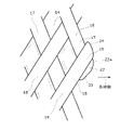
- FIG. 8 is an enlarged view of the end portion of the braided body 16 after the wire removal step as viewed from the outside in the radial direction.
- FIG. 9 is an enlarged view of the end portion of the braided body 16 after the wire removal step as viewed from the outside along a direction inclined with respect to the radial direction.
- FIG. 10 is an enlarged sectional view taken along the line CC of FIG. As shown in FIGS. 8 to 10, in the state after the wire removal step, the tip portion 22 of the first strand 17 projecting from the side surface on the tip side of the second strand 18 at the end of the braided body 16. Is formed.
- the first strand 17 and the second strand 18 are joined at the plurality of intersections 19 by the tip portion 22 of the first strand 17.
- the radial outer surface 22a of the tip portion 22 of the first strand 22 is also pressed by the covering member 34.
- the radial outer surface 22a of the tip portion 22 of the first strand (one strand) becomes the radial outer surface 18a of the second strand 18 (the other strand) at the intersection 19. It is arranged at the same position in the radial direction (vertical direction in FIG. 10) as in 10) or inside the radial direction (lower side in FIG. 10).
- the radial outer surface 22a of the tip portion 22 of the first strand is the above-mentioned flat surface.
- the end portion of the braided body 16 projects from the side surface on the tip end side of the first wire 17 located on the outer peripheral side.
- the tip of the second wire 18 located on the inner peripheral side is also formed, which has the same form as the tip 22 of the first wire 17 protruding from the side surface of the second wire 18 on the tip side.
- the tip portion 22 of one strand on the inner peripheral side is in the longitudinal direction of the other strand on the outer peripheral side (second strand 18). It has a one-sided protrusion 23 extending along the line so as to be away from the intersection 19.
- the protruding portion 23 on one side is exaggerated. The reason why the one-side protruding portion 23 is formed in this way is that when the braided body 16 is irradiated with the laser beam 60, the outer peripheral side of the braided body 16 is covered with the covering member 34, and the tip portion 22 of one of the strands is covered.
- the portion that cannot escape radially outward escapes in the circumferential direction. It is thought that it extends like this.
- the other side protruding portion 24 protruding from the intersection 19 so as to protrude in the longitudinal direction of the other strand in the portion adjacent to the intersection 19 of the other strand (second strand 18). Is also formed.
- the contact area between the end portion of the braided body 16 and the inner layer 14 can be increased by each of the protruding portion 23 on one side and the protruding portion 24 on the other side. This makes it more difficult for the end portion of the braided body 16 to come off from the inner layer 14.
- an outer layer 30 made of resin is formed on the outer peripheral side of the intermediate member 20 to form the distal shaft 12. Then, the catheter 10 is formed by connecting the proximal shaft 50 to the distal shaft 12.
- the method for manufacturing the catheter 10 described above it is possible to prevent the thickness of the tip of one of the strands from increasing due to the irradiation of the laser beam 60 at the time of cutting. Further, it is not necessary to join the first strand 17 and the second strand 18 in advance by laser irradiation at the intersection 19 before cutting the first strand 17 and the second strand 18 by laser irradiation. This makes it possible to reduce the number of laser irradiations.
- a portion of the braided body 16 located on the tip end side of the intersection 19 of one of the first strands 17 and the second strands 18 and the other strands. Is irradiated with a laser beam 60 to cut one of the strands and weld the first strand 17 and the second strand 18.
- the joint strength of the first wire 17 and the second wire 18 can be further increased by the solidified portion.
- the covering member 34 is more likely to be in close contact with the outer peripheral side end of the braided body 16, so that the thickness at the tip of one of the strands is large due to the irradiation of the laser beam. It becomes easier to suppress the situation.
- the inner member arranged on the inner peripheral side of the braided body 16 is the inner layer 14 forming the catheter 10, the wire rod as a jig arranged inside at the time of manufacturing is pulled and stretched, and after the catheter 10 is formed, the catheter 10 is used. When the wire is pulled out, the presence of the inner layer 14 makes it easier to pull out the wire. This makes it easy to manufacture the catheter 10.
- the first strand 17 and the second strand 18 are arranged at the intersection 19, and one strand is arranged radially inside the other strand.
- the radial outer surface 22a of the tip portion 22 of one strand which is joined so as to overlap in the radial direction and protrudes toward the tip side from the widthwise side surface of the portion including the intersection of the other strands, is the intersection 19. It is placed at the same radial position as the radial outer surface of the other strand in, or inside the radial side. As a result, the thickness of the tip of one of the strands is less than or equal to the thickness of the intersection 19.
- the thickness of the outer layer 30 of the catheter 10 it is not necessary to increase the thickness of the outer layer 30 of the catheter 10 so that the braided body 16 does not protrude from the outer peripheral surface of the outer layer 30, and it is possible to suppress non-uniformity in the radial direction of the outer peripheral surface of the outer layer 30.
- the thickness of the tip portion 22 of one of the strands arranged inward in the radial direction at the intersection portion 19 is equal to or less than the thickness of the intersection portion 19 has been described.
- the thickness of the tip portion of the other strands arranged radially outside from the intersection 19 is also less than or equal to the thickness of the intersection 19, and the tip of the other strand is
- the radial outer surface of the portion is arranged at the same radial position as the radial outer surface of the other strand at the intersection 19 or inside the radial direction.
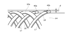
- FIG. 11 shows that in the catheter of the comparative example, the welded portion at the tip of the braided body 16a becomes large.
- the braided body 16a is irradiated with a laser beam to cut the first wire 17 and the second wire 18, and the first wire 17 is used.
- the inner layer 14 and the outer peripheral side of the braided body 16a are not covered with the covering member in advance.
- the portion where the first wire 17 passes through the inner peripheral side of the second wire 18 and is located from the side surface to the tip side of the second wire 18 is bulged outward in the radial direction by irradiation with a laser beam.
- the joint portions 40a and 40b having the bulging portions are formed, and the first strands 17 and the second strands 18 are welded at the joint portions 40a and 40b.
- the joint portions 40a and 40b are raised outward in the radial direction without the radial outer surface being suppressed by the covering member. Then, in the state of FIG.
- the joint portions 40a and 40b swell outward in the radial direction from the outermost peripheral surface of the portion of the braided body 16a excluding the tip portions of the first strands 17 and the second strands 18, and the joint portions 40a
- the radial outer end of the above-mentioned outermost peripheral surface is located outside by the radial dimension d (for example, about several tens of ⁇ m).
- the thickness of the joints 40a and 40b, which are the tips of the first wire 17 and the second wire 18, is larger than the thickness of the intersection adjacent to the joint.
- FIG. 12 is a diagram showing a coating process in another method for manufacturing a catheter according to the embodiment.
- a sheet 35 made of silicone rubber having a small thickness for example, a thickness of about 100 ⁇ m
- the sheet 35 is translucent and has no adhesive force.
- the intermediate portion in the width direction (horizontal direction in FIG. 14) of the sheet 35 is placed on the outer peripheral side of the portion including the planned welding portion of the braided body 16 (FIG. 3) of the intermediate member 20 composed of the inner layer 14 and the braided body 16. Put it on.
- block-shaped magnets 36 are arranged on the upper sides of both ends in the width direction of the sheet 35, and the magnetic force acting between the block-shaped magnets 36 and the upper surface of the magnetic material plate 37 such as an iron plate arranged on the upper surface of the fixing base is used. Both ends of the sheet 35 are fixed to the plate 37.
- the welding process is performed in this state.
- the intermediate member 20 is rotated little by little, and laser light is irradiated from above the intermediate member 20 to the vicinity of the planned cutting portion.
- other configurations are the same as those of FIGS. 1 to 10.
- FIG. 13 is a diagram showing a coating process in another method for manufacturing a catheter according to the embodiment.
- FIG. 14 is a cross-sectional view showing an outer covering portion 43 of the covering member 41 used in the manufacturing method of FIG.
- the inner covering portion 42 is formed of, for example, a sheet made of silicone rubber having a small thickness, similar to the sheet 35 shown in FIG.
- a long member having a C-shaped diameter cross section is used for the outer covering portion 43.
- the outer covering portion 43 is formed, for example, by fitting a long shaft-shaped member and then heat-shrinking it to remove a part of the circumferential direction of the shrink tube over the entire length in the longitudinal direction.
- the outer peripheral side of the braided body 16 (FIG. 3) is covered with the covering member 41.
- an intermediate member 20 whose longitudinal end is gripped by a jig (not shown) is placed on the upper surface of a plate 37 made of a magnetic material such as an iron plate placed on a fixed base as shown in FIG. 13 (a). do.
- the longitudinal direction of the inner covering portion 42 (vertical direction of FIGS. 13 (b) and 13 (c)) on the outer peripheral side of the portion of the intermediate member 20 including the planned welded portion of the braided body 16. Place the middle part. After that, as shown in FIG.
- the outer covering portion 43 is fitted from above the inner covering portion 42 to the portion including the arrangement portion of the inner covering portion 42 in the intermediate member 20.
- the outer peripheral side of the inner layer 14 (FIG. 3) and the braided body 16 can be covered with the covering member 41, and the outer peripheral side end of the braided body 16 can be pressed by the covering member 41.
- the cutting step is performed in a state where both ends of the inner covering portion 42 protruding from the outer covering portion 43 in the longitudinal direction are fixed to the plate 37 by, for example, the magnetic force of the magnet 36 shown in FIG.
- other configurations are the same as the configurations of FIGS. 1 to 10 or the configuration of FIG.
- FIG. 15 is a diagram corresponding to FIG. 8 in another example catheter of the embodiment.
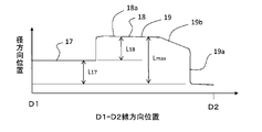
- FIG. 16 is a diagram showing an outline of the D1-D2 cross section of FIG.
- the first strand 17 and the second strand 18 are at the intersection 19, and one strand is radially inside the other strand. They are joined so that they are arranged so that they overlap in the radial direction.
- a recess 19b is provided on the tip end side of at least the radial outer surface 18a of the intersection 19, and the tip end of one of the strands is the widthwise side surface 19a of the tip end side of the intersection 19 (the intersection of the other strands).
- the maximum thickness Lmax of the intersection 19 between the first strand 17 and the second strand 18 is the thickness L 17 and L of the first strand 17 and the second strand 18, respectively.
- the sum of 18 (L 17 + L 18 ) is obtained, but the thickness of the intersection 19 gradually decreases toward the widthwise side surface 19a on the tip side in the portion including the recess 19b.
- the arrangement step of arranging the braided body 16 on the cylindrical outer peripheral surface 14a of the inner layer 14 and the outer peripheral side of the inner layer 14 and the braided body 16 are provided.
- the cutting step is performed. In the cutting step, from the outside of the covering member 34, one of the strands on the inner peripheral side of the intersection 19 of the first strand 17 and the second strand 18 in the braided body 16 is on the tip side from the intersection 19.
- the laser beam is irradiated to the portion including the positioned portion and the tip end side of the radial outer surface of the other strand which is the outer peripheral side at the intersection 19. Then, one of the strands is cut and the first strand 17 and the second strand 18 are welded. At this time, due to the energy of the laser beam, the portion of one of the strands located on the tip side of the intersection 19 is melted and cut, and the tip side of the radial outer surface 18a of the intersection 19 is also melted and recessed. The irradiation position and irradiation energy of the laser beam are adjusted so that 19b is formed. At this time, as shown in FIG.
- the laser is formed not only in the intersection 19 but also in the portion continuous from the intersection 19 toward the axial center side in the longitudinal direction of the other strand. Light may be applied to the other strand.
- a coating removing step of removing the covering member 34 and a strand removing step of removing an excess portion of the first strand 17 are performed in the same manner as in each of the above examples.
- FIG. 15 shows the joint portion at the intersection 19 where the first strand 17 is arranged on the inner circumference side of the second strand 18, but the second strand 18 is the inner circumference of the first strand 17.
- a joint at the intersection arranged on the side is formed in the same manner.
- the catheter of this example it is possible to prevent the tip portion of one strand having a large thickness from being formed from the widthwise side surface 19a of the other strand on the outer peripheral side to the tip side at the intersection 19. It is not necessary to increase the thickness of the outer layer of the catheter so that the braid 16 does not protrude from the outer peripheral surface of the outer layer, and it is possible to suppress non-uniformity in the radial direction of the outer peripheral surface of the outer layer 30.
- other configurations and operations are the same as those of FIGS. 1 to 11.
- the recess 19b may be formed so as to reach the inner peripheral side surface of the intersection.
- a part of the braided body of the catheter has a configuration in which the tip end portion 22 of one of the strands is formed from the side surface of the intersection portion 19 as shown in FIG. 8, and the intersection portion 22 is formed in another portion as shown in FIG. There may be a configuration in which the recess 19b is formed on the side surface of 19.
- the covering member a configuration other than the shrink tube or the combination of the inner covering portion and the outer covering portion may be used.
- a transparent or translucent cellophane tape or a translucent low-adhesive tape may be wound around the outer peripheral side of the intermediate member and brought into close contact with the outer peripheral side of the braided body 16.
- a cylinder formed of glass or a long member having an arc-shaped cross section may be used.
- the catheter 10 includes the inner layer 14 on the inner peripheral side of the braided body 16
- the catheter may be configured not to include the inner layer.
- the braided body is cut and welded by irradiating a necessary portion with a laser beam while being wound around a shaft portion formed in a jig.
- the shaft portion of the jig corresponds to the inner member.
- a resin coating as a lubricant is applied to the shaft of the jig in advance before winding the braid.
- an outer layer is formed on the outer peripheral side of the braid. In this configuration, it is not necessary to provide an inner layer on the catheter, so that the cost of the catheter can be reduced by reducing the number of parts.
- first and second strands are cut by irradiation with a laser beam, and the first and second strands are cut. Welding has been described, but in the cutting process, one of the first and second strands is cut by irradiation with a laser beam, and the first and second strands are welded separately from the cutting process. The process may be performed. Further, in the configuration of each of the above examples, the case where the first wire 17 and the second wire 18 are formed of metal wires of the same metal material as each other has been described, but the first wire 17 and the second wire 18 have been described. May be formed of different metallic materials.
- the catheter manufactured by the manufacturing method of the present invention is a guide extension catheter
- the catheter manufactured by the manufacturing method of the present invention is not limited to this, and is not limited to this, and is inside the outer layer. It can be a variety of catheters with braids.
Landscapes
- Health & Medical Sciences (AREA)
- Life Sciences & Earth Sciences (AREA)
- Biophysics (AREA)
- Pulmonology (AREA)
- Engineering & Computer Science (AREA)
- Anesthesiology (AREA)
- Biomedical Technology (AREA)
- Heart & Thoracic Surgery (AREA)
- Hematology (AREA)
- Animal Behavior & Ethology (AREA)
- General Health & Medical Sciences (AREA)
- Public Health (AREA)
- Veterinary Medicine (AREA)
- Media Introduction/Drainage Providing Device (AREA)
Priority Applications (4)
| Application Number | Priority Date | Filing Date | Title |
|---|---|---|---|
| EP21915040.6A EP4268876A4 (en) | 2020-12-28 | 2021-12-07 | METHOD FOR MANUFACTURING A CATHETER, AND CATHETER |
| US18/256,993 US20240058572A1 (en) | 2020-12-28 | 2021-12-07 | Method for manufacturing catheter, and catheter |
| JP2022572956A JP7816174B2 (ja) | 2020-12-28 | 2021-12-07 | カテーテルの製造方法及びカテーテル |
| CN202180087362.7A CN116685369A (zh) | 2020-12-28 | 2021-12-07 | 导管的制备方法及导管 |
Applications Claiming Priority (2)
| Application Number | Priority Date | Filing Date | Title |
|---|---|---|---|
| JP2020-218281 | 2020-12-28 | ||
| JP2020218281 | 2020-12-28 |
Publications (1)
| Publication Number | Publication Date |
|---|---|
| WO2022145179A1 true WO2022145179A1 (ja) | 2022-07-07 |
Family
ID=82260396
Family Applications (1)
| Application Number | Title | Priority Date | Filing Date |
|---|---|---|---|
| PCT/JP2021/044950 Ceased WO2022145179A1 (ja) | 2020-12-28 | 2021-12-07 | カテーテルの製造方法及びカテーテル |
Country Status (5)
| Country | Link |
|---|---|
| US (1) | US20240058572A1 (https=) |
| EP (1) | EP4268876A4 (https=) |
| JP (1) | JP7816174B2 (https=) |
| CN (1) | CN116685369A (https=) |
| WO (1) | WO2022145179A1 (https=) |
Citations (4)
| Publication number | Priority date | Publication date | Assignee | Title |
|---|---|---|---|---|
| JP2001161824A (ja) * | 1999-12-10 | 2001-06-19 | Hitachi Cable Ltd | カテーテルチューブの製造方法 |
| US20080125752A1 (en) * | 2006-08-09 | 2008-05-29 | Boston Scientific Scimed, Inc. | Catheter assembly having a modified reinforcement layer |
| JP2014023811A (ja) * | 2012-07-30 | 2014-02-06 | Asahi Intecc Co Ltd | カテーテル |
| JP6080258B2 (ja) | 2013-01-30 | 2017-02-15 | 朝日インテック株式会社 | カテーテル |
Family Cites Families (5)
| Publication number | Priority date | Publication date | Assignee | Title |
|---|---|---|---|---|
| US6562022B2 (en) * | 2000-12-13 | 2003-05-13 | Advanced Cardiovascular Systems, Inc. | Catheter with enhanced reinforcement |
| JP4338546B2 (ja) * | 2004-02-20 | 2009-10-07 | ミヤチテクノス株式会社 | カテーテル加工方法 |
| WO2011008738A1 (en) * | 2009-07-13 | 2011-01-20 | Cook Incorporated | Swaged braided catheter and method of fabrication |
| US9486605B2 (en) * | 2011-07-15 | 2016-11-08 | Cook Medical Technologies Llc | Introducer sheath with braided filament securement mechanism |
| JP5780556B2 (ja) * | 2012-08-07 | 2015-09-16 | 朝日インテック株式会社 | カテーテル |
-
2021
- 2021-12-07 WO PCT/JP2021/044950 patent/WO2022145179A1/ja not_active Ceased
- 2021-12-07 JP JP2022572956A patent/JP7816174B2/ja active Active
- 2021-12-07 US US18/256,993 patent/US20240058572A1/en active Pending
- 2021-12-07 EP EP21915040.6A patent/EP4268876A4/en active Pending
- 2021-12-07 CN CN202180087362.7A patent/CN116685369A/zh active Pending
Patent Citations (4)
| Publication number | Priority date | Publication date | Assignee | Title |
|---|---|---|---|---|
| JP2001161824A (ja) * | 1999-12-10 | 2001-06-19 | Hitachi Cable Ltd | カテーテルチューブの製造方法 |
| US20080125752A1 (en) * | 2006-08-09 | 2008-05-29 | Boston Scientific Scimed, Inc. | Catheter assembly having a modified reinforcement layer |
| JP2014023811A (ja) * | 2012-07-30 | 2014-02-06 | Asahi Intecc Co Ltd | カテーテル |
| JP6080258B2 (ja) | 2013-01-30 | 2017-02-15 | 朝日インテック株式会社 | カテーテル |
Non-Patent Citations (1)
| Title |
|---|
| See also references of EP4268876A4 |
Also Published As
| Publication number | Publication date |
|---|---|
| CN116685369A (zh) | 2023-09-01 |
| JP7816174B2 (ja) | 2026-02-18 |
| JPWO2022145179A1 (https=) | 2022-07-07 |
| EP4268876A4 (en) | 2024-07-24 |
| EP4268876A1 (en) | 2023-11-01 |
| US20240058572A1 (en) | 2024-02-22 |
Similar Documents
| Publication | Publication Date | Title |
|---|---|---|
| JP6149431B2 (ja) | 医療用機器、カテーテルおよび医療用機器の製造方法 | |
| US11850375B2 (en) | Catheter devices and methods for making them | |
| US20080125752A1 (en) | Catheter assembly having a modified reinforcement layer | |
| WO2018216596A1 (ja) | カテーテル | |
| WO2006085498A1 (ja) | 医療用カテーテルチューブならびにその製造方法 | |
| JP6124563B2 (ja) | カテーテル用チューブの製造方法およびカテーテル用チューブの連続体 | |
| JP2024149737A (ja) | カテーテル | |
| WO2022145179A1 (ja) | カテーテルの製造方法及びカテーテル | |
| JP6201368B2 (ja) | 医療用機器 | |
| JP2014188216A (ja) | 医療用機器および医療用機器の製造方法 | |
| JP2014100333A (ja) | カテーテル用チューブの製造方法、カテーテル用チューブの連続体およびカテーテル用チューブ製造用の芯線 | |
| JP5957966B2 (ja) | 医療機器及び医療機器の製造方法 | |
| US12616816B2 (en) | Catheter devices and methods for making them | |
| JP7718082B2 (ja) | カテーテル及びカテーテルの製造方法 | |
| JP2013208355A (ja) | 医療機器及び医療機器の製造方法 | |
| JP2014100323A (ja) | カテーテル用チューブの製造方法 | |
| JP2014100327A (ja) | カテーテル用チューブの製造方法 | |
| JP6088809B2 (ja) | カテーテル用チューブの製造方法、カテーテル用チューブの連続体およびカテーテル用チューブ製造用の芯線 | |
| JP2023137533A (ja) | カテーテルおよび管状シャフトの製造方法 | |
| JP6526998B2 (ja) | カテーテル、およびカテーテルの製造方法 | |
| JP2014100336A (ja) | カテーテル用チューブの製造方法およびカテーテル用チューブの連続体 | |
| JP2014100321A (ja) | カテーテル用チューブの製造方法 | |
| JP2013208356A (ja) | 医療機器及び医療機器の製造方法 | |
| JP2014100330A (ja) | カテーテル用チューブの製造方法 | |
| JP2014100337A (ja) | カテーテル用チューブの製造方法 |
Legal Events
| Date | Code | Title | Description |
|---|---|---|---|
| 121 | Ep: the epo has been informed by wipo that ep was designated in this application |
Ref document number: 21915040 Country of ref document: EP Kind code of ref document: A1 |
|
| ENP | Entry into the national phase |
Ref document number: 2022572956 Country of ref document: JP Kind code of ref document: A |
|
| WWE | Wipo information: entry into national phase |
Ref document number: 18256993 Country of ref document: US |
|
| WWE | Wipo information: entry into national phase |
Ref document number: 202317041979 Country of ref document: IN |
|
| WWE | Wipo information: entry into national phase |
Ref document number: 202180087362.7 Country of ref document: CN |
|
| WWE | Wipo information: entry into national phase |
Ref document number: 2021915040 Country of ref document: EP |
|
| NENP | Non-entry into the national phase |
Ref country code: DE |
|
| ENP | Entry into the national phase |
Ref document number: 2021915040 Country of ref document: EP Effective date: 20230728 |