WO2022131012A1 - タンクシステム及びクリーナシステム - Google Patents
タンクシステム及びクリーナシステム Download PDFInfo
- Publication number
- WO2022131012A1 WO2022131012A1 PCT/JP2021/044401 JP2021044401W WO2022131012A1 WO 2022131012 A1 WO2022131012 A1 WO 2022131012A1 JP 2021044401 W JP2021044401 W JP 2021044401W WO 2022131012 A1 WO2022131012 A1 WO 2022131012A1
- Authority
- WO
- WIPO (PCT)
- Prior art keywords
- tank
- region
- fluid
- cleaner
- discharge
- Prior art date
- Legal status (The legal status is an assumption and is not a legal conclusion. Google has not performed a legal analysis and makes no representation as to the accuracy of the status listed.)
- Ceased
Links
Images




Classifications
-
- B—PERFORMING OPERATIONS; TRANSPORTING
- B05—SPRAYING OR ATOMISING IN GENERAL; APPLYING FLUENT MATERIALS TO SURFACES, IN GENERAL
- B05B—SPRAYING APPARATUS; ATOMISING APPARATUS; NOZZLES
- B05B1/00—Nozzles, spray heads or other outlets, with or without auxiliary devices such as valves, heating means
-
- B—PERFORMING OPERATIONS; TRANSPORTING
- B05—SPRAYING OR ATOMISING IN GENERAL; APPLYING FLUENT MATERIALS TO SURFACES, IN GENERAL
- B05B—SPRAYING APPARATUS; ATOMISING APPARATUS; NOZZLES
- B05B1/00—Nozzles, spray heads or other outlets, with or without auxiliary devices such as valves, heating means
- B05B1/14—Nozzles, spray heads or other outlets, with or without auxiliary devices such as valves, heating means with multiple outlet openings; with strainers in or outside the outlet opening
-
- B—PERFORMING OPERATIONS; TRANSPORTING
- B60—VEHICLES IN GENERAL
- B60S—SERVICING, CLEANING, REPAIRING, SUPPORTING, LIFTING, OR MANOEUVRING OF VEHICLES, NOT OTHERWISE PROVIDED FOR
- B60S1/00—Cleaning of vehicles
- B60S1/02—Cleaning windscreens, windows or optical devices
- B60S1/46—Cleaning windscreens, windows or optical devices using liquid; Windscreen washers
- B60S1/48—Liquid supply therefor
Definitions
- the present invention relates to a tank system and a cleaner system.
- Patent Document 1 the cleaning liquid stored in the tank provided in the vehicle is pressure-fed to the switching valve by an electromagnetic pump, and the switching valve uses either the rear washer nozzle or the camera washer nozzle to supply the cleaning liquid.
- a cleaning system that selectively feeds is disclosed.
- an air bleeding path may be formed from the electromagnetic pump to the tank as an air bleeding path for pressure-feeding the cleaning liquid by the electromagnetic pump.
- the pump when the pump is operated, a part of the cleaning liquid returns from the pump to the tank through the air bleeding path. At this time, there is a problem that an abnormal noise is generated when the cleaning liquid is discharged into the tank.
- an object of the present invention is to provide a tank system and a cleaner system capable of preventing the generation of sound when the fluid is discharged into the tank.
- the tank system is With the tank A supply unit attached to the tank and having an opening for supplying a fluid into the tank, It comprises a discharge section attached to the opening and configured to discharge into the tank while suppressing the momentum of the fluid flowing through the supply section.
- the cleaner system is With the above tank system, A cleaner that injects the fluid stored in the tank to the cleaning target, A pump that supplies the fluid from the tank to the cleaner, A first pipeline for sending the fluid supplied by the pump to the cleaner, A second pipeline for returning the fluid supplied by the pump to the tank, and It is a cleaner system equipped with The supply section is provided between the second pipeline and the tank.
- the present invention it is possible to provide a tank system and a cleaner system capable of preventing the generation of sound when a fluid is discharged into a tank.
- FIG. 1 is a block diagram showing a cleaner system according to the present embodiment.
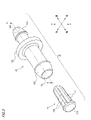
- FIG. 2 is a perspective view showing a joining member (supply portion, discharge portion) of the tank system included in the cleaner system of FIG.
- FIG. 3 is an exploded perspective view showing a supply portion and a discharge portion of the joining member shown in FIG.
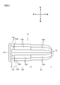
- FIG. 4 is a sectional view taken along the line AA of the supply unit shown in FIG.
- FIG. 5 is a side view of the discharge portion shown in FIG.
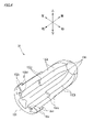
- FIG. 6 is a perspective view of the discharging portion.
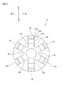
- FIG. 7 is a rear view of the discharging portion.
- FIG. 8 is a perspective view of the discharge portion according to the modified example.
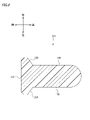
- FIG. 9 is a cross-sectional view taken along the line BB of the emission portion shown in FIG.
- FIG. 1 is a configuration diagram showing a cleaner system 1 according to the present embodiment.
- the cleaner system 1 includes a cleaner 2, a pump 3, a first pipeline 4, a second pipeline 5, and a tank system 6.
- the tank system 6 includes a tank 10 and a joining member 20.
- the cleaner 2 is used to inject the cleaning fluid (an example of the fluid) stored in the tank 10 of the tank system 6 onto the cleaning target.
- the object to be cleaned is, for example, an in-vehicle sensor mounted on a vehicle, a vehicle lamp, a vehicle window, or the like.
- In-vehicle sensors include, for example, cameras, LiDAR, lasers and the like.
- LiDAR is an abbreviation for Light Detection and Ringing or Laser Imaging Detection and Ringing.
- the pump 3 is a pump that sucks the cleaning fluid stored in the tank 10 and sends the cleaning fluid toward the cleaner 2.
- the pump 3 is connected to the tank 10 via a suction pipe line 9. Further, the pump 3 is connected to the branch portion 7 via the supply pipe line 8.
- the branch portion 7 branches the supply line 8 into the first line 4 and the second line 5.
- the pump may be configured to be directly attached to the tank 10 without going through the suction pipe line 9.
- the first pipeline 4 is a pipeline for supplying the cleaning fluid sent out by the pump 3 to the cleaner 2.
- the first pipeline 4 connects the branch portion 7 and the cleaner 2.
- the second pipeline 5 is a pipeline for returning the cleaning fluid sent out by the pump 3 to the tank 10.
- the second pipeline 5 connects the branch portion 7 and the joining member 20.
- the tank 10 of the tank system 6 is a tank in which a cleaning fluid for cleaning an object to be cleaned is housed.
- the joining member 20 of the tank system 6 is a member for flowing the cleaning fluid returned from the pump 3 into the tank 10.
- the joining member 20 is a member provided between the second pipeline 5 and the tank 10.
- the cleaner system 1 having such a configuration operates as follows, for example.
- an operation signal is transmitted from the cleaner control unit (not shown) to the pump 3.
- the pump 3 sucks the cleaning fluid from the tank 10 through the suction pipe line 9.
- the cleaning fluid cannot be sufficiently sucked into the pump. Therefore, when the cleaning fluid sucked by the pump 3 is sent out to the cleaner 2, it is necessary to perform an air bleeding process for removing the air remaining in the pump 3.
- the air bleeding process of the pump 3 is performed through the second pipeline 5 branched at the branch portion 7.
- the cleaning fluid remaining in the pump 3 is pumped to the joining member 20 through the supply pipe 8 and the second pipe 5 together with the air remaining in the pump 3, and the joining member 20 is pressed. It is returned to the tank 10 through.
- the pump 3 supplies the cleaning fluid to the cleaner 2 via the supply line 8 and the first line 4. As a result, the cleaning fluid is injected toward the object to be cleaned from the injection port of the cleaning nozzle (not shown) provided in the cleaner 2.
- FIG. 2 is a perspective view showing the joining member 20 of the tank system 6.
- FIG. 3 is an exploded perspective view showing the supply portion 21 and the release portion 31 of the joining member 20.
- FIG. 4 is a sectional view taken along the line AA in FIG. 3 of the supply unit 21.
- 5 is a side view of the release unit 31
- FIG. 6 is a perspective view of the release unit 31
- FIG. 7 is a rear view of the release unit 31.
- the joining member 20 has a supply unit 21 and a release unit 31.
- the supply section 21 and the release section 31 are formed of, for example, a resin material.
- the resin material forming the supply unit 21 and the release unit 31 is preferably made of the same type of resin material having the same heat shrinkage rate.
- the supply unit 21 is formed in a cylindrical shape.
- the rear end of the supply section 21 is formed as a connecting section 121 to which the second pipeline 5 is connected.
- the tip of the connection portion 121 is provided with an opening 122 into which the air and the cleaning fluid sent from the pump 3 flow. The air and the cleaning fluid flowing in from the opening 122 flow through the flow path in the supply unit 21.
- the front end of the supply portion 21 is formed as an insertion portion 123 to be inserted into the tank 10.
- the tip of the insertion portion 123 is provided with an opening 124 through which the air flowing through the supply portion 21 and the cleaning fluid flow out. The air and cleaning fluid flowing out of the opening 124 are discharged into the tank 10.
- a flange 125 is formed in the central portion of the supply unit 21 so as to project in the radial direction of the supply unit 21.
- the discharge portion 31 is formed of a lid portion 131 constituting the front end portion and a plurality of ribs 132 formed on the rear side of the lid portion 131.
- the discharge unit 31 is a member attached to the opening 124 of the supply unit 21.
- the flow path 126 is a flow path of the connecting portion 121 constituting the rear side of the flange 125.
- the flow path 127 is a flow path of the insertion portion 123 constituting the front side of the flange 125.
- the flow path 128 is a flow path of the flange 125.
- the diameter of the flow path 126 of the connecting portion 121 is formed to be smaller than the diameter of the flow path 127 of the insertion portion 123.
- the diameter of the flow path 128 of the flange 125 is formed to be smaller than the diameter of the flow path 126 of the connection portion 121. Further, the path from the connecting portion 121 to the flange 125, that is, the path between the flow path 126 and the flow path 128 is formed in a tapered shape in which the diameter gradually decreases from the flow path 126 toward the flow path 128. .. The path from the flange 125 to the insertion portion 123, that is, the path between the flow path 128 and the flow path 127 is formed in a reverse taper shape in which the diameter gradually increases from the flow path 128 toward the flow path 127. Thereby, the flow velocity of the cleaning fluid in the opening 124 of the insertion portion 123 can be made slower than the flow velocity of the cleaning fluid in the opening 122 of the connecting portion 121.
- the lid portion 131 of the discharge portion 31 is formed in a disk shape.
- the diameter of the lid portion 131 is formed to be larger than the inner diameter of the opening 124 of the supply portion 21.
- the lid portion 131 is attached to the supply portion 21 so as to close the opening 124 of the supply portion 21.
- the lid 131 functions to prevent the flow of the cleaning fluid flowing out of the opening 124 of the supply section 21.
- the rib 132 of the discharge portion 31 is erected from the central axis along the length direction of the discharge portion 31 toward the radial direction of the discharge portion 31 (an example of the second direction). That is, the rib 132 has a direction (second direction) in which the cleaning fluid intersects the direction (an example of the first direction) in which the cleaning fluid flows in the supply unit 21 when the discharge unit 31 is attached to the supply unit 21. It is erected toward one example). In this example, six ribs 132 are erected radially at equal intervals. The number of ribs 132 is preferably an even number, and more preferably 4 or more.
- the number of ribs 132 By setting the number of ribs 132 to an even number, it is possible to disperse the force applied to the ribs 132 when the release section 31 is press-fitted into the supply section 21 and improve the rigidity of the release section 31. Further, by setting the number of ribs 132 to four or more, it is possible to increase the fitting force when the discharge unit 31 is attached to the supply unit 21.
- Each rib 132 has a first region 133 to a third region 135 in the length direction (front-back direction).
- the first rib portion 132a is provided in the first region 133.
- a second rib portion 132b is provided in the second region 134.
- the third region 135 is provided with a third rib portion 132c.
- the first region 133 is a region provided on the lid portion 131 side, and is formed so as to be continuous with the lid portion 131.
- the first rib portion 132a provided in the first region 133 has a diameter of a virtual circle passing through the apex (outer circumference) of the first rib portion 132a of each rib 132 in a cross section orthogonal to the direction in which the cleaning fluid flows (front-back direction). , It is formed so as to be larger than the inner diameter of the opening 124 of the supply unit 21.
- the diameter of the virtual circle passing through the apex of each first rib portion 132a is formed to be the same as the diameter of the lid portion 131.
- the second region 134 is a region formed on the side opposite to the lid portion 131 (rear side of the first region 133) with the first region 133 in between.
- the diameter of the virtual circle passing through the apex of each second rib portion 132b in the cross section orthogonal to the direction in which the cleaning fluid flows is larger than the inner diameter of the opening 124 of the supply portion 21. Is also formed to be small.
- the third region 135 is a region formed between the first region 133 and the second region 134.
- the diameter of the virtual circle passing through the apex of each third rib portion 132c in the cross section orthogonal to the direction in which the cleaning fluid flows is the inner diameter of the opening 124 of the supply portion 21. It is formed to have the same diameter or slightly larger than the inner diameter of the opening 124.
- a groove 136 extending along the longitudinal direction (front-back direction) of the discharge portion 31 is formed between the adjacent ribs 132. These groove portions 136 serve as grooves through which the cleaning fluid flows.
- the second region 134 provided with the second rib portion 132b of the discharge portion 31 and the third region 135 provided with the third rib portion 132c pass through the opening 124 of the supply portion 21 into the insertion portion 123, that is, the flow path. It is housed in 127.
- the discharge portion 31 is attached to the supply portion 21 in a state where the third rib portion 132c of the third region 135 is press-fitted into the supply portion 21 and the first rib portion 132a of the first region 133 is in contact with the edge portion of the opening 124. Will be.
- the discharge holes 137 are holes that open in the radial direction of the joining member 20 (supply portion 21 and discharge portion 31), respectively.
- the cleaning fluid flows in the supply unit 21 in the front-rear direction (first direction) along the groove 136 of the discharge unit 31, and then hits the lid portion 131 of the discharge unit 31 to stop the flow in the front-rear direction and release the cleaning fluid. It is radially discharged in the radial direction (second direction) of the joining member 20 through the hole 137. In this way, the momentum (for example, the flow velocity) of the cleaning fluid returned to the tank 10 through the supply unit 21 is suppressed by being discharged in a direction different from the flow direction of the cleaning fluid in the supply unit 21. ..
- the area of the discharge hole 137 formed between the opening 124 of the supply unit 21 and the lid 131 of the discharge unit 31 is a plane in which the total area of the discharge holes 137 is orthogonal to the front-rear direction of the flow path 128. It is set to be larger than the area of the flow path 128 derived from the diameter R (FIG. 4). If the total area of each discharge hole 137 is smaller than the area of the flow path 128, the flow rate of the cleaning fluid returned from the second pipeline 5 to the tank 10 via the supply unit 21, that is, discharge from the discharge hole 137. The amount of the cleaning fluid discharged may be reduced, and the flow rate of the cleaning fluid supplied to the cleaner 2 via the first pipeline 4 may be unintentionally increased.
- the cleaning nozzle of the cleaner 2 is supplied to the cleaner 2 through the first pipeline 4 (not shown). It is possible to prevent the injection amount of the cleaning fluid injected from the cleaning object from exceeding a desired range.
- the tank system 6 is attached to the tank 10, a supply unit 21 which is attached to the tank 10 and has an opening 124 for supplying a cleaning fluid into the tank 10, and an opening 124.
- a discharge unit 31 configured to discharge the cleaning fluid into the tank 10 while suppressing the momentum of the cleaning fluid flowing through the supply unit 21 is provided. According to this configuration, the momentum of the cleaning fluid flowing in the supply unit 21 is suppressed by the discharge unit 31. Therefore, it is possible to reduce the noise generated when the cleaning fluid hits the inner wall of the tank 10 when the cleaning fluid is discharged into the tank 10.
- the discharge unit 31 is in the radial direction (first direction) of the supply unit 21 that intersects the front-rear direction (an example of the first direction) of the supply unit 21, which is the direction in which the cleaning fluid flows in the supply unit 21.
- first direction the radial direction
- front-rear direction an example of the first direction
- the momentum of the cleaning fluid is suppressed.
- the momentum of the cleaning fluid is suppressed by changing the flow direction of the cleaning fluid by the discharge unit 31, so that the sound generated when the fluid is discharged into the tank 10 can be reliably reduced. ..
- the discharge portion 31 is formed so as to have a diameter larger than the inner diameter of the opening 124, and a lid that stops the flow of the cleaning fluid in the front-rear direction of the supply portion 21 at the end portion of the opening 124. It has a section 131 and a plurality of ribs 132 housed in the supply section 21 and erected in the radial direction of the supply section 21. Then, when the discharge unit 31 is attached to the supply unit 21, a discharge hole 137 from which the cleaning fluid is discharged is formed between the opening 124 and the lid portion 131. Therefore, it is possible to easily realize a configuration in which the cleaning fluid is discharged into the tank 10 in a radial direction different from the front-rear direction of the supply unit 21, which is the direction in which the cleaning fluid flows in the supply unit 21.
- each of the plurality of ribs 132 is a region continuous from the lid portion 131 and passes through the respective vertices of the first rib portion 132a in a cross section orthogonal to the front-rear direction of the supply portion 21.
- the first region 133 in which the diameter of the virtual circle is larger than the inner diameter of the opening 124 and the region provided on the opposite side of the lid portion 131 across the first region 133, and each of the third rib portion 132c.
- the diameter of the virtual circle passing through the apex of the second region 134 is smaller than the inner diameter of the opening 124, and the region is provided between the first region and the second region, and each of the second rib portions 132b is provided.
- the discharge unit 31 When the third region 135 having the same diameter as the opening 124 comes into contact with the inner surface of the supply unit 21, the discharge unit 31 is press-fitted into the supply unit 21. This makes it possible to improve workability when attaching the discharge unit 31 to the supply unit 21 while forming the discharge hole 137 of an appropriate size.
- the cleaner system 1 includes a tank system 6, a cleaner 2 that injects a cleaning fluid stored in the tank 10 to a cleaning target, and a pump 3 that supplies the cleaning fluid from the tank 10 to the cleaner 2.
- a first pipeline 4 for sending the cleaning fluid supplied by the pump 3 to the cleaner 2 and a second pipeline 5 for returning the cleaning fluid supplied by the pump 3 to the tank 10 are provided.
- a joining member 20 (supply section 21 and discharge section 31) is provided between the second pipeline 5 and the tank 10.
- the fluid is discharged in the radial direction of the supply unit 21 (an example of the second direction) intersecting the front-rear direction (an example of the first direction) of the supply unit 21 which is the direction in which the cleaning fluid flows in the supply unit 21. It is configured to do. That is, the discharge direction of the cleaning fluid discharged into the tank 10 from the discharge hole 137 of the discharge unit 31 is substantially orthogonal to the flow direction of the cleaning fluid flowing through the flow paths 126, 128, 127 in the supply unit 21. , Not limited to this example.
- FIG. 8 is a perspective view of the discharge unit 231 according to the modified example
- FIG. 9 is a cross-sectional view taken along the line BB in FIG. 8 of the discharge unit 231.
- a gradient portion 238 is provided between the lid portion 131 and the groove portion 136 of the discharge portion 231.
- the inclined portion 238 is formed as an inclined surface that gradually becomes lower from the lid portion 131 to the groove portion 136.
- the slope portion 238 is formed so as to have an angle of about 45 ° with respect to the longitudinal direction (front-back direction) of the groove portion 136.
- an in-vehicle sensor, a vehicle lamp, a vehicle window, and the like have been described as cleaning objects, but the object in which the tank system 6 and the cleaner system 1 are used is not limited to the vehicle. Further, the tank system 6 of the present embodiment is not limited to the one used for the cleaner system 1.
Landscapes
- Engineering & Computer Science (AREA)
- Water Supply & Treatment (AREA)
- Mechanical Engineering (AREA)
- Cleaning In General (AREA)
Abstract
タンクシステムは、タンクと、タンクに取り付けられてタンク内へ流体を供給する開口(124)を有する供給部(21)と、開口(124)に取り付けられて供給部(21)を流れる流体の勢いを抑制しながらタンク内に放出するように構成された放出部(31)と、を備えている。
Description
本発明は、タンクシステム及びクリーナシステムに関する。
特許文献1には、車両に設けられるタンクに貯留された洗浄液が電磁ポンプにより切替バルブに圧送され、当該切替バルブは、送給される洗浄液を、リア・ウォッシャノズルとカメラ・ウォッシャノズルの何れかに択一的に送給する洗浄システムが開示されている。
特許文献1に開示のような洗浄システムにおいて、電磁ポンプにより洗浄液を圧送するためのエア抜き経路として、電磁ポンプからタンクへ向けてエア抜き経路が形成される場合がある。この場合、ポンプ作動時に、エア抜き経路を介して洗浄液の一部がポンプからタンクへと戻ることとなる。このとき、タンク内に当該洗浄液が放出される際の異音発生が問題となっている。
そこで、本発明は、タンク内へ流体が放出される際の音の発生を防止可能なタンクシステム及びクリーナシステムを提供することを目的とする。
上記目的を達成するために、本発明の一側面に係るタンクシステムは、
タンクと、
前記タンクに取り付けられ、前記タンク内へ流体を供給する開口を有する供給部と、
前記開口に取り付けられて、前記供給部を流れる前記流体の勢いを抑制しながら前記タンク内に放出するように構成された放出部と、を備えている。
タンクと、
前記タンクに取り付けられ、前記タンク内へ流体を供給する開口を有する供給部と、
前記開口に取り付けられて、前記供給部を流れる前記流体の勢いを抑制しながら前記タンク内に放出するように構成された放出部と、を備えている。
また、本発明の一側面に係るクリーナシステムは、
上記のタンクシステムと、
前記タンク内に貯留される前記流体を洗浄対象へ噴射するクリーナと、
前記タンクから前記クリーナへ向けて前記流体を供給するポンプと、
前記ポンプにより供給された前記流体を前記クリーナへと送るための第一管路と、
前記ポンプにより供給された前記流体を前記タンクへ戻すための第二管路と、
を備えた、クリーナシステムであって、
前記第二管路と前記タンクとの間に前記供給部が設けられている。
上記のタンクシステムと、
前記タンク内に貯留される前記流体を洗浄対象へ噴射するクリーナと、
前記タンクから前記クリーナへ向けて前記流体を供給するポンプと、
前記ポンプにより供給された前記流体を前記クリーナへと送るための第一管路と、
前記ポンプにより供給された前記流体を前記タンクへ戻すための第二管路と、
を備えた、クリーナシステムであって、
前記第二管路と前記タンクとの間に前記供給部が設けられている。
本発明によれば、タンク内へ流体が放出される際の音の発生を防止可能なタンクシステム及びクリーナシステムを提供することができる。
本発明の実施形態について図面を参照しながら説明する。なお、本実施形態の説明では、説明の便宜上、「左右方向」、「上下方向」、「前後方向」について適宜言及する場合がある。これらの方向は、図2に示す接合部材20について、設定された相対的な方向である。
図1を参照して、本実施形態に係るタンクシステム6を搭載するクリーナシステム1について説明する。図1は、本実施形態に係るクリーナシステム1を示す構成図である。
図1に示すように、クリーナシステム1は、クリーナ2と、ポンプ3と、第一管路4と、第二管路5と、タンクシステム6と、を備える。タンクシステム6は、タンク10と、接合部材20と、を有する。
図1に示すように、クリーナシステム1は、クリーナ2と、ポンプ3と、第一管路4と、第二管路5と、タンクシステム6と、を備える。タンクシステム6は、タンク10と、接合部材20と、を有する。
クリーナ2は、タンクシステム6のタンク10内に貯留されている洗浄流体(流体の一例)を洗浄対象へ噴射するために用いられる。洗浄対象物は、例えば、車両に搭載されている車載センサ、車両用灯具、あるいは車両のウインドウ等である。車載センサには例えばカメラ、LiDAR、レーザ等が含まれる。LiDARとは、Light Detection and RangingまたはLaser Imaging Detection and Rangingの略語である。
ポンプ3は、タンク10内に貯留されている洗浄流体を吸引し、当該洗浄流体をクリーナ2に向けて送り出すポンプである。ポンプ3は、吸引管路9を介してタンク10に接続されている。また、ポンプ3は、供給管路8を介して分岐部7に接続されている。分岐部7は、供給管路8を第一管路4と第二管路5とに分岐するものである。なお、ポンプは、吸引管路9を介さずに、タンク10に直接取り付けられる構成であってもよい。
第一管路4は、ポンプ3により送り出された洗浄流体をクリーナ2へと供給するための管路である。第一管路4は、分岐部7とクリーナ2との間を接続している。
第二管路5は、ポンプ3により送り出された洗浄流体をタンク10へ戻すための管路である。第二管路5は、分岐部7と接合部材20との間を接続している。
タンクシステム6のタンク10は、洗浄対象物を洗浄するための洗浄流体が収容されているタンクである。
タンクシステム6の接合部材20は、ポンプ3から戻される洗浄流体をタンク10に流入させるための部材である。接合部材20は、第二管路5とタンク10との間に設けられる部材である。
このような構成のクリーナシステム1は、例えば、以下のように動作する。
クリーナシステム1を作動させるためのクリーナボタン等が操作されると、クリーナ制御部(図示省略)からポンプ3に作動信号が送信される。作動信号を受信したポンプ3は、タンク10から吸引管路9を介して洗浄流体を吸引する。このとき、ポンプ3内に空気が残留していると、ポンプ内に洗浄流体を十分に吸引することができない。そのため、ポンプ3により吸引した洗浄流体をクリーナ2に送り出す際には、ポンプ3内に残留している空気を取り除くエア抜き処理を行う必要がある。本例では、分岐部7で分岐されている第二管路5を介して、ポンプ3のエア抜き処理を行う。このエア抜き処理により、ポンプ3内に残留していた空気とともに、ポンプ3内に残留していた洗浄流体が供給管路8及び第二管路5を通して接合部材20に圧送され、接合部材20を介してタンク10へと戻される。ポンプ3は、エア抜き処理の後に、供給管路8及び第一管路4を介して、洗浄流体をクリーナ2に供給する。これにより、クリーナ2に設けられた洗浄ノズル(不図示)の噴射口から洗浄流体が洗浄対象物に向けて噴射される。
クリーナシステム1を作動させるためのクリーナボタン等が操作されると、クリーナ制御部(図示省略)からポンプ3に作動信号が送信される。作動信号を受信したポンプ3は、タンク10から吸引管路9を介して洗浄流体を吸引する。このとき、ポンプ3内に空気が残留していると、ポンプ内に洗浄流体を十分に吸引することができない。そのため、ポンプ3により吸引した洗浄流体をクリーナ2に送り出す際には、ポンプ3内に残留している空気を取り除くエア抜き処理を行う必要がある。本例では、分岐部7で分岐されている第二管路5を介して、ポンプ3のエア抜き処理を行う。このエア抜き処理により、ポンプ3内に残留していた空気とともに、ポンプ3内に残留していた洗浄流体が供給管路8及び第二管路5を通して接合部材20に圧送され、接合部材20を介してタンク10へと戻される。ポンプ3は、エア抜き処理の後に、供給管路8及び第一管路4を介して、洗浄流体をクリーナ2に供給する。これにより、クリーナ2に設けられた洗浄ノズル(不図示)の噴射口から洗浄流体が洗浄対象物に向けて噴射される。
次に、図2から図7を参照して、本実施形態に係るタンクシステム6の接合部材20について説明する。図2は、タンクシステム6の接合部材20を示す斜視図である。図3は、接合部材20の供給部21と放出部31とを示す分解斜視図である。図4は、供給部21の図3におけるA-A断面図である。図5は、放出部31の側面図であり、図6は、放出部31の斜視図であり、図7は、放出部31の背面図である。
図2及び図3に示すように、接合部材20は、供給部21と、放出部31と、を有する。供給部21及び放出部31は、例えば、樹脂材料によって形成されている。供給部21及び放出部31を形成する樹脂材料は、熱収縮率が同じ同種の樹脂材料から構成されることが好ましい。
供給部21は、円筒状に形成されている。
供給部21の後方側の端部は、第二管路5が接続される接続部121として形成されている。接続部121の先端部には、ポンプ3から送られてくる空気及び洗浄流体が流入する開口122が設けられている。開口122から流入した空気及び洗浄流体は、供給部21内の流路を流れる。
供給部21の後方側の端部は、第二管路5が接続される接続部121として形成されている。接続部121の先端部には、ポンプ3から送られてくる空気及び洗浄流体が流入する開口122が設けられている。開口122から流入した空気及び洗浄流体は、供給部21内の流路を流れる。
供給部21の前方側の端部は、タンク10に挿入される挿入部123として形成されている。挿入部123の先端部には、供給部21内を流れた空気及び洗浄流体が流出する開口124が設けられている。開口124から流出した空気及び洗浄流体は、タンク10内へ放出される。
供給部21の中央部には、供給部21の径方向に突出するフランジ125が形成されている。フランジ125は、供給部21の挿入部123がタンク10の挿入孔(図示省略)を通してタンク10に取り付けられたとき、当該挿入孔に挿入されずにタンク10の外側でタンク10の筐体部(図示省略)に固定される部位である。
放出部31は、前方側の端部を構成する蓋部131と、蓋部131の後方側に形成された複数のリブ132とから形成されている。放出部31は、供給部21の開口124に取り付けられる部材である。
次に、供給部21の内部構造について図4を参照して説明する。
図4に示すように、供給部21内には、洗浄流体が流れる流路126,127,128が形成されている。流路126は、フランジ125よりも後方側を構成する接続部121の流路である。流路127は、フランジ125よりも前方側を構成する挿入部123の流路である。流路128は、フランジ125の流路である。接続部121の流路126の径は、挿入部123の流路127の径よりも小さくなるように形成されている。フランジ125の流路128の径は、接続部121の流路126の径よりもさらに小さくなるように形成されている。また、接続部121からフランジ125にかけての経路、すなわち流路126と流路128との間の経路は、流路126から流路128に向かって径が徐々に小さくなるテーパ状に形成されている。フランジ125から挿入部123にかけての経路、すなわち流路128と流路127との間の経路は、流路128から流路127に向かって径が徐々に大きくなる逆テーパ状に形成されている。これにより、挿入部123の開口124における洗浄流体の流速を、接続部121の開口122における洗浄流体の流速よりも遅くすることが可能である。
図4に示すように、供給部21内には、洗浄流体が流れる流路126,127,128が形成されている。流路126は、フランジ125よりも後方側を構成する接続部121の流路である。流路127は、フランジ125よりも前方側を構成する挿入部123の流路である。流路128は、フランジ125の流路である。接続部121の流路126の径は、挿入部123の流路127の径よりも小さくなるように形成されている。フランジ125の流路128の径は、接続部121の流路126の径よりもさらに小さくなるように形成されている。また、接続部121からフランジ125にかけての経路、すなわち流路126と流路128との間の経路は、流路126から流路128に向かって径が徐々に小さくなるテーパ状に形成されている。フランジ125から挿入部123にかけての経路、すなわち流路128と流路127との間の経路は、流路128から流路127に向かって径が徐々に大きくなる逆テーパ状に形成されている。これにより、挿入部123の開口124における洗浄流体の流速を、接続部121の開口122における洗浄流体の流速よりも遅くすることが可能である。
次に、放出部31について図5から図7を参照して詳しく説明する。
放出部31の蓋部131は、円盤状に形成されている。蓋部131の径は、供給部21の開口124の内径よりも大きくなるように形成されている。蓋部131は、供給部21の開口124を塞ぐように供給部21に取り付けられる。蓋部131は、供給部21の開口124から流出される洗浄流体の流れを抑止するように機能する。
放出部31の蓋部131は、円盤状に形成されている。蓋部131の径は、供給部21の開口124の内径よりも大きくなるように形成されている。蓋部131は、供給部21の開口124を塞ぐように供給部21に取り付けられる。蓋部131は、供給部21の開口124から流出される洗浄流体の流れを抑止するように機能する。
放出部31のリブ132は、放出部31の長さ方向に沿った中心軸から放出部31の径方向(第二方向の一例)に向かって立設されている。すなわち、リブ132は、放出部31が供給部21に取り付けられた際に洗浄流体が供給部21内で流れる方向(第一方向の一例)を軸として当該方向に交差する方向(第二方向の一例)に向かって立設されている。本例では、6本のリブ132が等間隔で放射状に立設されている。リブ132の数は、偶数本であることが好ましく、4本以上であることがさらに好ましい。リブ132の数を偶数本とすることで、放出部31を供給部21に圧入する際にリブ132にかかる力を分散させ、放出部31の剛性を向上させることができる。また、リブ132の数を4本以上とすることで、供給部21に放出部31が取り付けられた際の嵌合力を高めることができる。
リブ132は、それぞれ長さ方向(前後方向)における第一領域133~第三領域135を有する。第一領域133には第一リブ部132aが設けられている。第二領域134には第二リブ部132bが設けられている。第三領域135には第三リブ部132cが設けられている。
第一領域133は、蓋部131側に設けられる領域であり、蓋部131から連続するように形成されている。第一領域133に設けられた第一リブ部132aは、洗浄流体が流れる方向(前後方向)に直交する断面において各リブ132の第一リブ部132aの頂点(外周)を通る仮想円の直径が、供給部21の開口124の内径よりも大きくなるように形成されている。例えば、各第一リブ部132aの頂点を通る仮想円の直径は、蓋部131の直径と同じ大きさに形成されている。
第二領域134は、第一領域133を挟んで蓋部131とは反対側(第一領域133よりも後方側)に形成された領域である。第二領域134に設けられた第二リブ部132bは、洗浄流体が流れる方向に直交する断面において各第二リブ部132bの頂点を通る仮想円の直径が、供給部21の開口124の内径よりも小さくなるように形成されている。
第三領域135は、第一領域133と第二領域134との間に形成された領域である。第三領域135に設けられた第三リブ部132cは、洗浄流体が流れる方向に直交する断面において各第三リブ部132cの頂点を通る仮想円の直径が、供給部21の開口124の内径と同径、あるいは開口124の内径よりも僅かに大きくなるように形成されている。
隣り合うリブ132の間には、放出部31の長手方向(前後方向)に沿って延びる溝部136が形成される。これらの溝部136が、洗浄流体が流れる溝となる。
放出部31の第二リブ部132bが設けられている第二領域134と第三リブ部132cが設けられている第三領域135とが供給部21の開口124を通して挿入部123内、すなわち流路127に収容される。放出部31は、第三領域135の第三リブ部132cが供給部21に圧入され、第一領域133の第一リブ部132aが開口124の縁部に接触された状態で供給部21に取り付けられる。
放出部31が供給部21に取り付けられた際に、第一領域133と第三領域135との間に形成される段差、すなわち第一リブ部132aと第三リブ部132cとの間の段差132dが供給部21の開口124の縁部に接触することにより、供給部21の開口124と放出部31の蓋部131との間に放出孔137が形成される(図2参照)。放出孔137は、それぞれ接合部材20(供給部21及び放出部31)の径方向に開口する孔である。
洗浄流体は、供給部21内を放出部31の溝部136に沿った前後方向(第一方向)に流れた後に、放出部31の蓋部131に当たることで前後方向への流れが止められ、放出孔137を通って接合部材20の径方向(第二方向)へ放射状に放出される。このように、供給部21を通ってタンク10内に戻される洗浄流体の勢い(例えば、流速)は、供給部21内での洗浄流体の流れ方向と異なる方向へ放出されることにより抑制される。
なお、供給部21の開口124と放出部31の蓋部131との間に形成される放出孔137の面積は、各放出孔137を合計した面積が流路128の前後方向に直交する面における径R(図4)から導き出される流路128の面積よりも大きくなるように設定されている。仮に、各放出孔137を合計した面積が流路128の面積よりも小さいと、第二管路5から供給部21を介してタンク10へ戻される洗浄流体の流量、すなわち、放出孔137から放出される洗浄流体の放出量が少なくなり、第一管路4を介してクリーナ2へ供給される洗浄流体の流量が意図せずに増えてしまう場合がある。したがって、各放出孔137を合計した面積が流路128の面積よりも大きくなるように設定することで、第一管路4を介してクリーナ2へ供給され、クリーナ2の洗浄ノズル(不図示)から洗浄対象物へ噴射される洗浄流体の噴射量が所望の範囲を超えてしまうことを防止できる。
以上説明したように、実施形態に係るタンクシステム6は、タンク10と、タンク10に取り付けられ、タンク10内へ洗浄流体を供給する開口124を有する供給部21と、開口124に取り付けられて、供給部21を流れる洗浄流体の勢いを抑制しながらタンク10内に放出するように構成された放出部31と、を備えている。この構成によれば、供給部21内を流れる洗浄流体の勢いが放出部31によって抑制される。そのため、タンク10内へ洗浄流体が放出される際にタンク10の内壁に洗浄流体が当たることに発生する音を低減させることができる。
また、タンクシステム6によれば、放出部31は、供給部21内で洗浄流体が流れる方向である供給部21の前後方向(第一方向の一例)と交差する供給部21の径方向(第二方向の一例)に流体を放出することで、洗浄流体の勢いを抑制する。このように、放出部31により洗浄流体の流れる方向を変化させることで洗浄流体の勢いが抑制されるので、タンク10内へ流体が放出される際に発生する音を確実に低減することができる。
また、タンクシステム6によれば、放出部31は、開口124の内径よりも大径となるように形成され、開口124の端部において供給部21の前後方向への洗浄流体の流れを止める蓋部131と、供給部21内に収容されて供給部21の径方向に向かって立設された複数のリブ132と、を有する。そして、放出部31が供給部21に取り付けられた際に、開口124と蓋部131との間に洗浄流体が放出される放出孔137が形成される。このため、供給部21内での洗浄流体の流れる方向である供給部21の前後方向とは異なる径方向へ向けて洗浄流体をタンク10内へ放出する構成を簡便に実現できる。
また、タンクシステム6によれば、複数のリブ132のそれぞれは、蓋部131から連続する領域であって、供給部21の前後方向に直交する断面において第一リブ部132aのそれぞれの頂点を通る仮想円の直径が開口124の内径よりも大きい第一領域133と、第一領域133を挟んで蓋部131とは反対側に設けられる領域であって、第三リブ部132cのぞれぞれの頂点を通る仮想円の直径が開口124の内径よりも小さい第二領域134と、第一領域と第二領域との間に設けられる領域であって、第二リブ部132bのぞれぞれの頂点を通る仮想円の直径が開口124の内径と同径である第三領域135と、を有している。このため、各リブ132の第一領域133と第三領域135との間に形成される段差132dが供給部21の開口124に当接することで、洗浄流体が供給部21の径方向に沿って放出される放出孔137を形成することができる。また、第三領域135よりも小径の第二領域134を供給部21に挿入させることで第二領域134が案内部として機能しつつ、第二領域134よりも大径であって供給部21の開口124と同径の第三領域135が供給部21の内面に接触することで、供給部21に放出部31が圧入される。これにより、適切なサイズの放出孔137を形成しつつ、放出部31を供給部21に取り付ける際の作業性を向上できる。
また、実施形態に係るクリーナシステム1は、タンクシステム6と、タンク10内に貯留される洗浄流体を洗浄対象へ噴射するクリーナ2と、タンク10からクリーナ2へ向けて洗浄流体を供給するポンプ3と、ポンプ3により供給された洗浄流体をクリーナ2へと送るための第一管路4と、ポンプ3により供給された洗浄流体をタンク10へ戻すための第二管路5と、を備える。そして、第二管路5とタンク10との間に接合部材20(供給部21と放出部31)が設けられている。この構成によれば、クリーナ2により洗浄対象を洗浄するためのクリーナシステム1において、ポンプ3により洗浄流体をクリーナ2へ向けて圧送するためのエア抜き経路として、ポンプ3からタンク10へ第二管路5が形成されている。上記タンクシステム6を備えたクリーナシステム1においても、ポンプ3からタンク10に戻ってくる洗浄流体がタンク10内に放出される際の音の発生を抑制することができる。
以上、本発明の実施形態について説明をしたが、本発明の技術的範囲が本実施形態の説明によって限定的に解釈されるべきではないのは言うまでもない。本実施形態は単なる一例であって、請求の範囲に記載された発明の範囲内において、様々な実施形態の変更が可能であることが当業者によって理解されるところである。本発明の技術的範囲は請求の範囲に記載された発明の範囲及びその均等の範囲に基づいて定められるべきである。
上記実施形態では、供給部21内で洗浄流体が流れる方向である供給部21の前後方向(第一方向の一例)と交差する供給部21の径方向(第二方向の一例)に流体を放出するように構成されている。すなわち、放出部31の放出孔137からタンク10内に放出される洗浄流体の放出方向は、供給部21内の流路126,128,127を流れる洗浄流体の流れ方向と略直交しているが、この例に限られない。
具体的には、放出孔137からタンク10内に放出される洗浄流体の放出方向は、供給部21内の流路126,128,127を流れる洗浄流体の流れ方向に一定の角度で交差していればよく、例えば、流れ方向に対して放出方向が45°程度の角度を有していればよい。この変形例に係る放出部231の構成について図8及び図9を参照して説明する。図8は、変形例に係る放出部231の斜視図であり、図9は、放出部231の図8におけるB-B断面図である。図8及び図9に示すように、放出部231の蓋部131と溝部136との間には勾配部238が設けられている。勾配部238は、蓋部131から溝部136にかけて徐々に低くなる傾斜面として形成されている。本例では、勾配部238は、溝部136の長手方向(前後方向)に対して、約45°の角度を有するように形成されている。このように蓋部131と溝部136との間に勾配部238を設けることで、供給部21の前後方向に交差する放出方向の範囲内において、洗浄流体を放出孔137から所望の方向に放出させることができる。
上記実施形態では、洗浄対象物として車載センサ、車両用灯具、車両のウインドウ等を挙げて説明したが、タンクシステム6及びクリーナシステム1が使用される対象物は車両に限られない。また、本実施形態のタンクシステム6は、クリーナシステム1に用いられるものには限られない。
本出願は、2020年12月18日出願の日本特許出願2020-210434号に基づくものであり、その内容はここに参照として取り込まれる。
Claims (5)
- タンクと、
前記タンクに取り付けられ、前記タンク内へ流体を供給する開口を有する供給部と、
前記開口に取り付けられて、前記供給部を流れる前記流体の勢いを抑制しながら前記タンク内に放出するように構成された放出部と、を備えている、タンクシステム。 - 前記放出部は、前記供給部内で前記流体が流れる方向である第一方向と交差する第二方向に前記流体を放出することで、前記流体の勢いを抑制する、請求項1に記載のタンクシステム。
- 前記放出部は、
前記開口の内径よりも大径となるように形成され、前記開口の端部において前記第一方向への前記流体の流れを止める蓋部と、
前記第一方向を軸として前記第二方向に向かって立設された複数のリブと、
を有し、
前記放出部が前記供給部に取り付けられた際に、前記開口と前記蓋部との間に前記流体が放出される放出孔が形成される、請求項2に記載のタンクシステム。 - 前記複数のリブのそれぞれは、
前記蓋部から連続する領域であって、前記第一方向に直交する断面において各リブの頂点を通る仮想円の直径が前記内径よりも大きい第一領域と、
前記第一領域を挟んで前記蓋部とは反対側に設けられる領域であって、前記直径が前記内径よりも小さい第二領域と、
前記第一領域と前記第二領域との間に設けられる領域であって、前記直径が前記内径と同径である第三領域と、を有している、請求項3に記載のタンクシステム。 - 請求項1から4のいずれか一項に記載のタンクシステムと、
前記タンク内に貯留される前記流体を洗浄対象へ噴射するクリーナと、
前記タンクから前記クリーナへ向けて前記流体を供給するポンプと、
前記ポンプにより供給された前記流体を前記クリーナへと送るための第一管路と、
前記ポンプにより供給された前記流体を前記タンクへ戻すための第二管路と、
を備えた、クリーナシステムであって、
前記第二管路と前記タンクとの間に前記供給部が設けられている、クリーナシステム。
Priority Applications (1)
| Application Number | Priority Date | Filing Date | Title |
|---|---|---|---|
| JP2022569855A JPWO2022131012A1 (ja) | 2020-12-18 | 2021-12-03 |
Applications Claiming Priority (2)
| Application Number | Priority Date | Filing Date | Title |
|---|---|---|---|
| JP2020-210434 | 2020-12-18 | ||
| JP2020210434 | 2020-12-18 |
Publications (1)
| Publication Number | Publication Date |
|---|---|
| WO2022131012A1 true WO2022131012A1 (ja) | 2022-06-23 |
Family
ID=82057617
Family Applications (1)
| Application Number | Title | Priority Date | Filing Date |
|---|---|---|---|
| PCT/JP2021/044401 Ceased WO2022131012A1 (ja) | 2020-12-18 | 2021-12-03 | タンクシステム及びクリーナシステム |
Country Status (2)
| Country | Link |
|---|---|
| JP (1) | JPWO2022131012A1 (ja) |
| WO (1) | WO2022131012A1 (ja) |
Citations (7)
| Publication number | Priority date | Publication date | Assignee | Title |
|---|---|---|---|---|
| JPS5272363U (ja) * | 1975-11-26 | 1977-05-30 | ||
| JPH0235981A (ja) * | 1988-07-25 | 1990-02-06 | Toko Giken Kogyo Kk | タンク内の洗浄装置 |
| JPH05123279A (ja) * | 1991-11-02 | 1993-05-21 | Taihei Shoko Kk | 球型タンク等の建造物或いは建築物の壁面の洗浄・塗膜剥離方法及びその装置 |
| JPH09174011A (ja) * | 1995-12-25 | 1997-07-08 | Furoo Techno Kk | タンク内の清掃方法とその装置 |
| JP2000309396A (ja) * | 1999-04-23 | 2000-11-07 | Asahi Soft Drinks Co Ltd | 容器の洗浄装置及び容器の洗浄方法 |
| JP3092991U (ja) * | 2002-09-24 | 2003-04-11 | 大京運輸有限会社 | アジテータ車のドラム内面自動洗浄システム |
| WO2018135469A1 (ja) * | 2017-01-23 | 2018-07-26 | 株式会社小糸製作所 | 車両用クリーナシステムおよび車両用クリーナシステムを備える車両 |
-
2021
- 2021-12-03 WO PCT/JP2021/044401 patent/WO2022131012A1/ja not_active Ceased
- 2021-12-03 JP JP2022569855A patent/JPWO2022131012A1/ja active Pending
Patent Citations (7)
| Publication number | Priority date | Publication date | Assignee | Title |
|---|---|---|---|---|
| JPS5272363U (ja) * | 1975-11-26 | 1977-05-30 | ||
| JPH0235981A (ja) * | 1988-07-25 | 1990-02-06 | Toko Giken Kogyo Kk | タンク内の洗浄装置 |
| JPH05123279A (ja) * | 1991-11-02 | 1993-05-21 | Taihei Shoko Kk | 球型タンク等の建造物或いは建築物の壁面の洗浄・塗膜剥離方法及びその装置 |
| JPH09174011A (ja) * | 1995-12-25 | 1997-07-08 | Furoo Techno Kk | タンク内の清掃方法とその装置 |
| JP2000309396A (ja) * | 1999-04-23 | 2000-11-07 | Asahi Soft Drinks Co Ltd | 容器の洗浄装置及び容器の洗浄方法 |
| JP3092991U (ja) * | 2002-09-24 | 2003-04-11 | 大京運輸有限会社 | アジテータ車のドラム内面自動洗浄システム |
| WO2018135469A1 (ja) * | 2017-01-23 | 2018-07-26 | 株式会社小糸製作所 | 車両用クリーナシステムおよび車両用クリーナシステムを備える車両 |
Also Published As
| Publication number | Publication date |
|---|---|
| JPWO2022131012A1 (ja) | 2022-06-23 |
Similar Documents
| Publication | Publication Date | Title |
|---|---|---|
| US20200198591A1 (en) | Foreign matter removal device and vehicle provided with same | |
| WO2019044399A1 (ja) | 車両用エアクリーナ | |
| US20200001834A1 (en) | Cleaning device intended for spraying at least one fluid onto a surface to be cleaned of a motor vehicle | |
| CN113365738B (zh) | 液体喷射喷嘴和车辆的传感器清洗装置 | |
| JP7474711B2 (ja) | 車両用クリーナおよび車両用クリーナユニット | |
| JP7565215B2 (ja) | 自動車の画像センサー表面の洗浄乾燥システム及び方法 | |
| US20220111822A1 (en) | Vehicular cleaner | |
| WO2004018109A1 (ja) | ウォッシャノズル及びウォッシャ装置 | |
| JP3820579B2 (ja) | 燃料供給装置 | |
| US12157440B2 (en) | Cleaner for vehicles, bracket for cleaners for vehicles, and cleaner unit for vehicles | |
| CN113226872B (zh) | 用于光学检测系统的清洁装置的流体喷嘴 | |
| KR20000035722A (ko) | 흡인 분사 펌프 | |
| WO2022131012A1 (ja) | タンクシステム及びクリーナシステム | |
| JP7527475B2 (ja) | 自動車両の表面を洗浄するための流体噴射装置及びシステム | |
| JP2021011150A (ja) | 洗浄装置 | |
| CN220405994U (zh) | 喷射器 | |
| JP2007218094A (ja) | ジェットポンプ | |
| JP6536074B2 (ja) | ヘッドランプ洗浄装置 | |
| JP2002155819A (ja) | 旋回槽構造 | |
| KR102540259B1 (ko) | 소화기의 분사노즐 구조 | |
| WO2023058486A1 (ja) | クリーナ | |
| JP2011143831A (ja) | 車両用灯具の洗浄装置 | |
| JP6941850B2 (ja) | ウォッシャーノズル | |
| JP2003035210A (ja) | 気化器 | |
| JP6493954B2 (ja) | 洗浄ノズル |
Legal Events
| Date | Code | Title | Description |
|---|---|---|---|
| 121 | Ep: the epo has been informed by wipo that ep was designated in this application |
Ref document number: 21906375 Country of ref document: EP Kind code of ref document: A1 |
|
| ENP | Entry into the national phase |
Ref document number: 2022569855 Country of ref document: JP Kind code of ref document: A |
|
| NENP | Non-entry into the national phase |
Ref country code: DE |
|
| 122 | Ep: pct application non-entry in european phase |
Ref document number: 21906375 Country of ref document: EP Kind code of ref document: A1 |